

Page 1
4-090-729-11(1)
TFT LCD Color
Computer Display
Operating Instructions
Mode d’emploi
Manual de i nstrucciones
US
FR
ES
SDM-P82
© 2002 Sony Corporation
Page 2
Owner’s Record
The model and serial numbers are locatedat the rear of the unit.
Recordthese numbersinthespaces provided below.Refer to them
whenever you call upon your dealer regarding this product.
Model No.
Serial No.
WARNING
Toprevent fire orshock hazard, donot exposethe
unit to rain or moisture.
Dangerously high voltages are present inside the
unit. Do not open the c abinet. Refer servicing to
qualified personnel only.
FCC Notice
This equipment hasbeen testedand found to comply with the limits
for a Class B digital device, pursuant to Part 15 of the FCC Rules.
These limits are designedto provide reasonable protection against
harmful interference in a residential installation. This equipment
generates, uses, andcan radiateradio frequency energy and, if not
installed and used in accordance with the instructions, may cause
harmfulinterference to radiocommunications. H owever,thereisno
guarantee that interference will notoccur ina particularinstallation.
If this equipment does cause harmful interference to radio or
television reception, which can be determined by turning the
equipment off and on, the user is encouraged to try to correct the
interference by one or more of the following m easures:
– Reorient or relocate the receiving antenna.
– Increase the s eparation between the equipment and receiver.
– Connect the equipment into an outlet on a circuit different from
that to which the receiver is connected.
– Consult the dealeroran experiencedradio/TVtechnicianforhelp.
You are cautioned that any changes or modifications not expressly
approved in this manual could void your authority to operate t his
equipment.
INFORMATION
This product complies with Swedish Nat ional Council for Metrology
(MPR) standards issued in December 1990 (MPR II) for very low
frequency (VLF) and extremely low frequency (ELF).
INFORMATION
Ce produit est conforme aux normes du Swedish National Council
for Metrology de décembre 1990 (MPRII) en ce qui concerne les
fréquences très basses (VLF) et extrêmementbasses (ELF).
INFORMACIÓN
Este producto cumple las normas del Consejo Nacional Sueco para
Metrología (MPR) emitidas en diciembrede 1990 (MPR II) para
frecuenciasmuy bajas (VLF) y frecuenciasextremadamentebajas (ELF).
NOTICE
This notice is applicable for USA/Canada only.
If shipped to USA/Canada, install only a UL LIST ED/ C SA
LABELLED power supply cord meeting the f ollowing
specifications:
SPECIFICATIONS
Plug Type Nema-Plug 5-15p
Cord Type SVT or SJT, minimum 3 × 18 AWG
Length Maximum 15 feet
Rating Minimum 7 A, 125 V
NOTICE
Cette notice s’applique aux Etats-Unis et au Canada
uniquement.
Si cet appareilest exportéauxEtats-Unis ou au Canada, utiliser
le cordon d’alimentation portant la mention UL LISTED/CSA
LABELLED et remplissant les conditions suivantes:
SPECIFICATIONS
Type de fiche Fiche Nema 5-15 broches
Cordon Type SVT ou SJT, minimum 3 × 18 AWG
Longueur Maximum 15 pieds
Tension Minimum 7 A, 125 V
ENERGY STAR Partner, Sony
As an
Corporation has determined that this
product meets the
guidelines for energy efficiency.
This monitor complies with the
TCO’99 guidelines.
NERGYSTAR
E
If you have any questions about this product, you may call:
Sony Customer Information Center
1-800-222-SONY (7669)
or write to:
Sony Customer Information Center
1 Sony Drive, Mail Drop #T1-11, Park Ridge, NJ 07656
Declaration of Conformity
Trade Name: SONY
Model No.: SDM-P82
Responsible Party: Sony Electronics Inc.
Address: 680 Kinderkamack Road, O radell,NJ 07649
Telephone No.: 201-930-6972
This device complies with Part 15 of the FCC Rules. Operation is
subject to the following two conditions: (1) This device may not
cause harmful interference, and (2) this device must accept any
interference received, including interference that may cause
undesired operation.
USA
2
Page 3

Table of Contents
Precautions............................................4
Identifyingpartsandcontrols..............................5
Setup..........................................7
Setup 1: Connect a computer equipped with the DVI output
connector(digitalRGB)............................7
Setup 2: Connect a computer equipped with the HD15 output
connector (analog RGB). . . . . . . . . . . . ................7
Setup 3: Connectthepowercord ..........................8
Setup 4: Bundlethecordsandcables.......................9
Setup 5: Turnonthemonitorandcomputer ..................9
Setup 6: Adjustingthetilt................................10
Selecting the input signal (INPUT button)
.................11
CustomizingYourMonitor.......................11
Navigatingthemenu....................................11
BACKLIGHT.......................................12
CONTRAST........................................12
BRIGHTNESS .....................................12
SCREEN (analog RGB signal only) . . . . . . ...............12
COLOR ...........................................14
GAMMA...........................................15
ZOOM............................................15
SMOOTHING......................................15
Additionalsettings......................................16
US
• Macintosh is a trademarklicensed to
Apple Computer, Inc., registered in the
U.S.A. a nd other countries.
• Windows
Microsoft Corporation in the United
States and other countries.
• IBM PC/AT and VGA are registered
trademarks of IBM Corporation of the
U.S.A.
• VESA and DDC
Video Electronics Standards
Association.
E
•
mark.
• All other product names mentioned
herein may be the trademarks or
registeredtrademarksoftheirrespective
companies.
•Furthermore,“”and“”arenot
mentionedineachcaseinthismanual.
is registered trademark of
are trademarksof the
NERGYSTAR is a U.S. registered
TechnicalFeatures .............................17
Powersavingfunction...................................17
Reducingthepowerconsumption(ECOmode)...............17
Automatic picture quality adjustment function
(analogRGBsignalonly)................................17
Troubleshooting................................18
On-screenmessages...................................18
Troublesymptomsandremedies..........................19
Self-diagnosis function . . . . . . ............................21
Specifications..................................21
TCO’99Eco-document....................................i
3
Page 4
Precautions
Warning on power connections
• Use the supplied power cord. If you use a different power cord,
be sure that it is compatible with your local power supply.
For the customers in the U.S.A.
If you do not use the appropriate cord, this monitor will not
conform to mandator y FCC standards.
For the customers in the UK
If you use the monitor in the UK, be sureto use theappropriate
UK power cord.
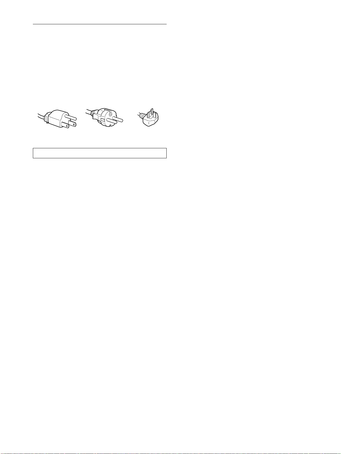
Example of plug types
for 100 to 120 V A C for 200 to 240 V AC for 240 V AC only
The equipment should be installed near an easily accessible outlet.
Installation
Do not install or leave the monitor:
• In places subject to extreme temperatures,for example near a
radiator, heating vent, or in direct sunlight. Subjecting the
monitor to extreme temperatures, such as in an automobile
parked in direct sunlight or near a heating vent, could cause
deformations of the casing or malfunctions.
• In places subject to mechanical vibration or shock.
• Near any equipment that generates a strong magnetic field,
such as a TV or various other household appliances.
• In places subjectto inordinateamounts of dust, dir t,orsand, for
example near an open window or an outdoor exit. If setting up
temporarily in an outdoor environment, be sure to take
adequate precautions against airborne dust and dirt. Otherwise
irreparable malfunctions could occur.
Handling the LCD screen
• Do not leave the LCDscreen facing the sunas it can damage
theLCDscreen.Takecarewhenyouplacethemonitorbya
window.
• Do not push on or scratch the LCD screen. Do not place a heavy
object on the LCD screen. This may cause the screen to lose
uniformity or cause LCD panel malfunctions.
• If the monitor is used in a cold place, a residual image may
appear on the screen. This is not a malfunction. The screen
returns tonormal as the temperature rises to a normaloperating
level.
• If a still picture is displayed for a long time, a residual image
may appear for a while. The residual image will eventually
disappear.
• The LCD panel becomes warm during operation. This is not a
malfunction.
Note on the LCD (Liquid Crystal Display)
Please note thatthe LCD screen is made with high-precision
technology. However, black points or bright points of light (red,
blue, or green) may appear constantl y on the LCD screen, and
irregular colored stripes or brightness may appear on the LCD
screen.Thisisnotmalfunction.
(Effective dots: more than 99.99%)
Replacement of the fluorescent tube
A specially designed fluorescent tube is installed as the lighting
apparatus for this monitor. If the screen becomes dark, unstable,
or does not turn on, replace the fluorescent tube with a new one.
Consult your Sony dealer when replacing the fluorescent tube.
Maintenance
• Be sureto unplug the power cord from the power outletbefore
cleaning your monitor.
• CleantheLCDscreenwithasoftcloth.Ifyouuseaglass
cleaning liquid, do not use any type of cleaner containing an
anti-static solution or similar additive as this may scratch the
LCD screen’s coating.
• Clean the cabinet, panel,and controls with a soft cloth lightly
moistened with a mild detergent solution. Do not use any type
of abrasivepad, scouringpowder, or solvent, such as alcoholor
benzine.
• Do not rub, touch, or tapthe surface of the screen with sharp or
abrasive itemssuch as a ballpoint pen or screwdriver. This type
of contact may result in a scratched pictur etube.
• Note that material deterioration or LCD screen coating
degradation may occur if the monitor is exposed to volatile
solvents such as insecticide, or if prolonged contact is
maintained with rubber or vinyl materials.
Transportation
• Disconnect all cables from the monitor and grasp the support
and base sections of the display stand firmly with both hands
whentransporting.If you dropthe monitor,you may beinjured
or the monitor may be damaged.
• When you transport thismonitor for repair or shipment,use the
original carton and packing materials.
Disposal of the monitor
• Do not dispose of this monitor with general
household waste.
• The fluorescent tube used in this monitor contains
mercury.Disposal of this monitor mustbe carriedout
in accordance to the regulations of your local
sanitation authority.
4
Page 5
Identifying parts and controls
See the pages in parentheses for further details.
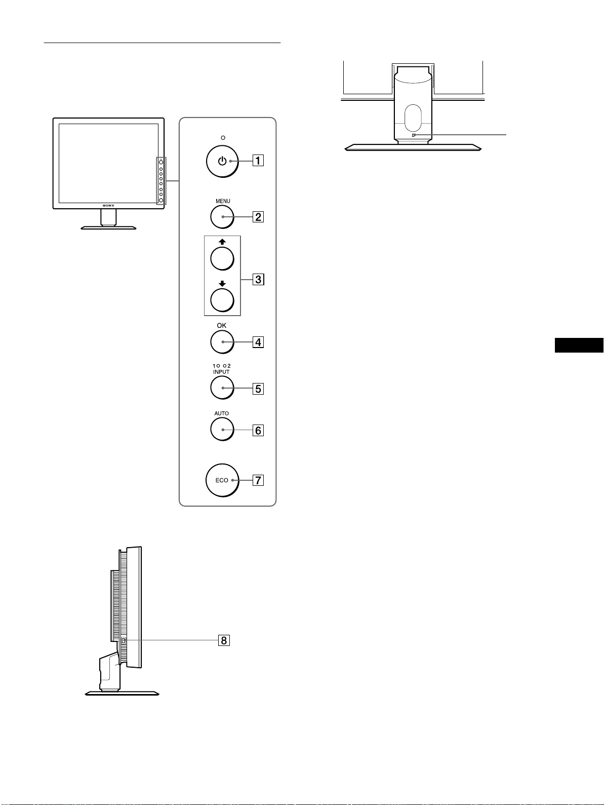
Front of the LCD display
Rear of the display stand
9
AAAA 1 (Power) switch and 1 (Power) indicator
(pages 9, 17, 21)
This switch turns the monitor on when the 1 (power)
indicator lights up in red. To turn the monitor off, press this
switch again.
If the 1 (power) indicator does notlight up, press the MAIN
POWER switch (8).
BBBB MENU button (page 11)
This button turns the menu screen on and off.
CCCC M/m buttons (page 11)
These buttons are used to select the menu items and make
adjustments.
Side view of the LCD display
DDDD OK button (page 11)
This button activates the selected menu item and adjustments
using with M/m buttons (3).
EEEE INPUT button and INPUT1/INPUT2 indicator
(page 11)
This button selects the connected computer for switching the
video input signals, and the corresponding indicator,
(INPUT1 or INPUT2) lights up.
FFFF AUTO button (page 12)
Press this button when the displayed picture seems poorly
adjusted. It makesfurther automatic adjustmentof the picture
quality for the current input signal.
GGGG ECO button (page 17)
Thisbuttonisusedtoreducethepowerconsumption.
HHHH MAIN POWER switch (page 9)
This switch turns the monitor’s main power on and off.
IIII Security Lock Hole
The security lockhole shouldbe applied with the Kensington
Micro Saver Security System.
Micro Saver Security System is a trademark of Kensington.
US
(continued)
5
Page 6
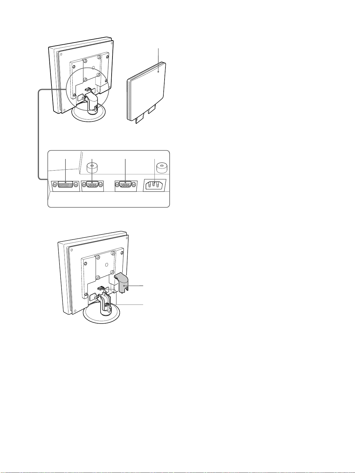
Rear of the LCD display
JJJJ Back cover (page 7)
Remove this cover when you connect cablesor cords.
qa qs qd qf
q;
KKKK DVI-D input connector (digital RGB) for INPUT1
(page 7)
This connectorinputs digital RGB video signals that comply
with DVI Rev. 1.0.
LLLL HD15 input connector (analog RGB) for INPUT1
(page 7)
ThisconnectorinputsanalogRGBvideosignals(0.700Vp-p,
positive) and sync signals.
MMMM HD15 input connector (analog RGB) for INPUT2
(page 7)
ThisconnectorinputsanalogRGBvideosignals(0.700Vp-p,
positive) and sync signals.
NNNN AC IN connector (page 8)
Connect the power cord (supplied).
OOOO Arm cover (page 9)
Remove this cover to bundle connecting cords and cables.
PPPP Cable holder (page 9)
This part secures cables and cords to the monitor.
qg
qh
6
Page 7

Setup
Before using your monitor, check that the following items are
included in your carton:
• LCD display
• Power cord
• HD15-HD15 video signal cable (analog RGB)
• DVI-D video signal cable (digital RGB)
• Windows Utility/Macintosh Utility Disk
• Warranty card
• This instruction manual
Setup 1:Connect a computer
equipped with the DVI
output connector (digital
RGB)
• Turn off the monitor and computerbefore connecting.
• When connecting the computerto the monitor’s HD15
input connector (analog RGB), refer to “Setup 2:
Connect a computer equipped with the HD15 output
connector (analog RGB).”
Note
Do not touch the pins of the video signal cable connector as this might
bend the pins.
1 Remove the back cover.
2 Using the supplied DVI-D video signal cable (digital
RGB), connect the computer to the monitor’sDVI-D
input connector (digital RGB) for INPUT1.
to the DVI-D input
connector (digital
RGB) for INPUT1
to the computer’s DVI output
connector (digital RGB)
DVI-D video signal cable
(digital RGB) (supplied)
Setup 2:Connect a computer
equipped with the HD15
output connector (analog
RGB)
Turn off the monitor and computer before connecting.
Note
Do not touch the pins of the videosignal cable connector as this might
bend the pins.
US
1 Remove the back cover.
(continued)
7
Page 8
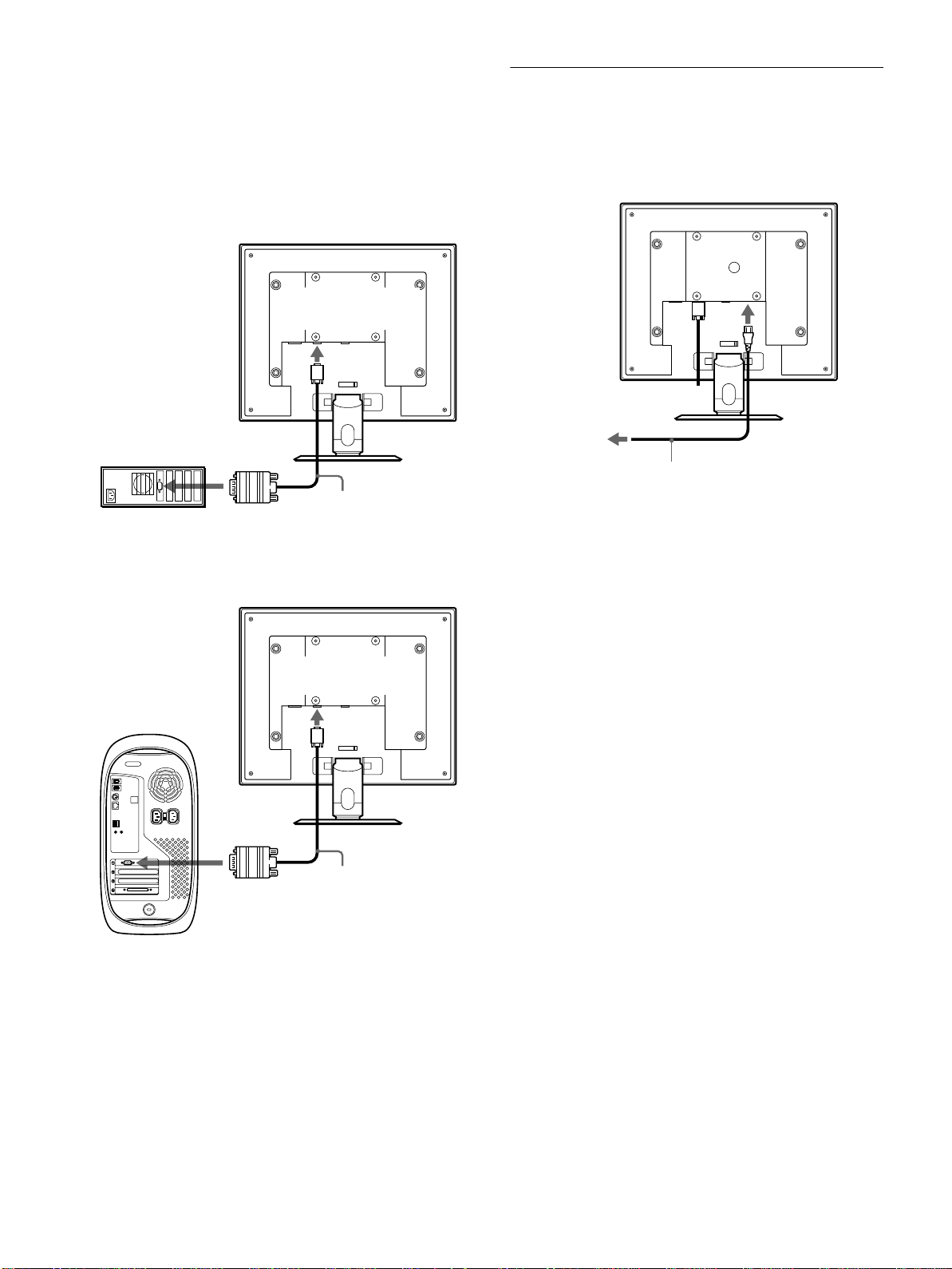
2 Using the supplied HD15-HD15 video signal cable
(analog RGB), connect the computer to the
monitor’s HD 15 input connector (analog RGB) for
INPUT 1 or INPUT2.
Connect the computer according to the following
illustrations.
Connecting to an IBM PC/AT or
xxxx
compatible computer
Setup 3:Connect the power c ord
1 Connect the supplied power cord to the monitor’s
AC IN connector.
2 Connect it to a power outlet.
to the computer’s HD15 output
connector (analog RGB)
IBM PC/AT or
compatible computer
Connecting to a Macintosh
xxxx
to the HD 15 input
connector(analogRGB)
for INPUT1 or INPUT2
HD15-HD15 video signal
cable (analog RGB)
(supplied)
to the HD 15 input
connector(analogRGB)
for INPUT1 or INPUT2
to AC IN
1
to power outlet
power cord (supplied)
2
to the computer’s
output connector
Macintosh
When connecting a Macintosh computer, use an adapter (not supplied)
if necessary. Connect the adaptertothe computer before connecting the
video signal cable.
HD15-HD15 video signal
cable (analog RGB)
(supplied)
8
Page 9

Setup 4:Bundle the cords and
Setup5:Turnonthemonitorand
cables
1 Remove the arm cover.
2 Bundle the cords and cables inside of the stand.
3 Secure the cables and cords with the cable holder.
4 Replace the arm cover and back cover.
1
arm cover
2
4
back cover
computer
1 PresstheMAIN POWERswitchon theleft side ofthe
monitor in the direction of [.
The 1 (power) indicator lights up in red.
MAIN POWER
2 Press the 1 (power) switch on the front right of the
monitor.
The 1 (power) indicator lights up in green.
lights in red
lights in green
US
3
Note
If you cannot bundle all of the cords and cables inside the stand, leave
them hanging down outside the stand.
3 Turn on the computer.
4 Press the INPUT button repeatedly and select the
desired input signal.
The selected input signal indicator lights up and the picture
appears on the screen.
Formore information,see“Selecting the input signal(INPUT
button)” on page 11.
The installation of your monitoris complete.If necessary,use the
monitor’s controls to adjust the picture (page 11).
(continued)
9
Page 10
If no picture appears on your screen
• Check that the power cord and the video signal cable are
properly connected.
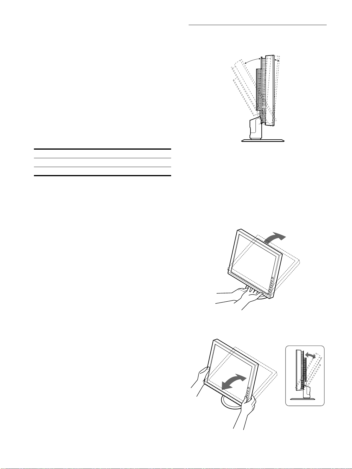
Setup 6:Adjusting the t ilt
This monitor can be adjusted within the angles shown below.
• If NO INPUT SIGNAL appears on the screen:
– The computer is in the power saving mode. Try pressing any
key on the keyboard or moving the mouse.
– Check that the input signal setting is correct by pressing the
INPUT button repeatedly (page 11).
• If CABLE DISCONNECTED appears on the screen:
– Check that the video signal cable is properly connected.
– Check that the input signal setting is correct by pressing the
INPUT button repeatedly (page 11).
• If OUT OF SCAN RANGE appearson the screen, reconnect
the old monitor. Then adjust the computer’sgraphicsboardin
the following ranges.
Horizontal frequency 28 – 92 kHz
Vertical frequency 56 – 85 Hz
Resolution 1280 × 1024 or less
For more information about on-screen messages, see “Trouble
symptoms and remedies” on page 19.
No need for specific drivers
The monitor complies with the “DDC” Plug & Play standard and
automaticallydetects all the monitor’s information. No specific driver
needs to be installed to the computer.
The first time you turnonyour computerafterconnecting themonitor, the
setup Wizardmay appear on the screen. In this case, followthe on-screen
instructions. The Plug & Play monitor is automatically selected so that
you can use thismonitor.
20°
5°
To use the monitor comfortably
Adjust the viewing angle of your monitor according to the height
of your desk and chair, and so that light is not reflected from the
screen to your eyes.
Note
When adjusting the screen tilt, proceed slowly and carefully, being sure
not to hit themonitor against the desk or the base of the display stand.
1 Grasp the lower middle part of the LCD panel while
holding the display stand, then, tilt the LCD panel
adequately backward.
The vertical frequency turns to 60 Hz.
Since flickers are unobtrusive on the monitor, you can use it as it is. You
do not need to set the vertical frequencyto any particular high value.
2 Grasp the lower sides of the LCD panel, then adjust
screen tilt.
10
Page 11
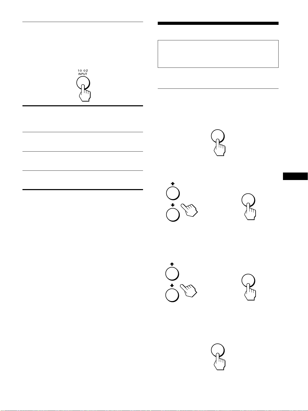
Selecting the input signal
(INPUT button)
Customizing Your Monitor
Press the INPUT button.
The input signal changeeach time you press this button as
follows.
On-screen
message)
(Appears about 5
seconds on the
upper left corner.)
INPUT1: DVI-D INPUT1 DVI-D input
INPUT1: HD15 INPUT1 HD15 input
INPUT2: HD15 INPUT2 HD15 input
Input indicator
lights up
Input signal
configuration
connector (digital
RGB) for INPUT1
connector (analog
RGB) for INPUT1
connector (analog
RGB) for INPUT2
Before making adjustments
Connect the monitor and the computer, and turn them on.
Wait for at least 30 minutes before making adjustments for the
best results.
You can make numerous adjustments to yourmonitorusing the
on-screenmenu.
Navigating the menu
1 Display the main menu.
Press the MENU button to display the main menu on your
screen.
MENU
2 Select the menu you want to adjust.
Press the M/m buttons to display the desired menu. Press the
OK button to select the menu item.
OK
US
,
3 Adjust the menu.
Press the M/m buttons to make the adjustment,then press the
OK button.
When you press the OK button, the setting is stored, then the
display returns to the previous menu.
OK
,
4 Close the menu.
Press the MENU button once to return to normal viewing. If
no buttons are pressed, the menu closes automatically after
about 45 seconds.
MENU
11
Page 12

Resetting the adjustments to the default
xxxx
settings
You can reset the adjustments using the RESET menu. Formore
information about resetting the adjustments, see “0 (RESET)”
on page 16.
BRIGHTNESS
Adjust the picture brightness (black level).
BR GHTNESSI
BACKLIGHT
Ifthescreenis too bright, adjustthe backlightandmakethescreen
easier to see.
Note
The backlight cannot be adjusted when the ECO mode is set to “ON”
(page 17).
BACKL GHTI
100
1280 1024 60Hzx/
EX I T
1 Press the MENU button.
The main menu appears on the screen.
2 Press the M/m buttons to select (BACKLIGHT)
and press the OK button.
The BACKLIGHT menu appears on the screen.
3 Press the M/m buttons to adjust the desired light
level.
CONTRAST
Adjust the picture contrast.
CONTRAST
100
1280 1024 60Hzx/
1 Press the MENU button.
The main menu appears on the screen.
2 Pressthe M/m buttons to select6 (CONTRAST) and
press the OK button.
The CONTRAST menu appears on the screen.
EX I T
100
1280 1024 60Hzx/
EX I T
1 Press the MENU button.
The main menu appears on the screen.
2PresstheM/m buttons to select 8 (BRIGHTNESS)
and press the OK button.
The BRIGHTNESS menu appears on the screen.
3PresstheM/m buttons to adjust the brightness.
SCREEN
Note
When receiving digital RGB signals from the DVI-D inputconnector
for INPUT1, adjustment is unnecessary.
Automatic picture quality adjustment
xxxx
(analog RGB signal only)
function
When the monitor receives an input signal, it
automatically adjusts the picture’s position and
sharpness (phase/pitch),and ensuresthata clear
picture appears on the screen (page 17).
Note
While the automatic picture quality adjustmentfunction is activated, only
(power) switch will operate.
the
1
If the automatic picture quality adjustment function of
this monitor seems to not completely adjust the picture
By pressing the AUTO button, you can make further automatic
adjustment of the picture quality for the current input signal
(page 5).
If you still need to make further adjustments to the
picture quality
Youcan manually adjust the picture’ssharpness (phase/pitch)and
position (horizontal/vertical position).
3 Press the M/m buttons to adjust the contrast.
12
If you need to eliminate a shift of the picture occurring
when the input signal has been changed
The shift is caused by the automatic picture quality adjustment
function. You can deactivate this function (page 14).
Page 13
These adjustments are stored in memory and automatically
recalledwhen the displayreceives the same input signal.
SCREEN
PHASE
P I TCH
H CENTER
V CENTER
AUTO
ON
1280 1024 60Hzx/
Adjust the picture’s sharpness manually
xxxx
EX I T
(PHASE/PITCH)
You can adjust the picture’s sharpness as follows. This
adjustment is effective when the computer is connected to the
monitor’s HD15 input connector (analog RGB).
1 Set the resolution to 1280 × 1024 on the computer.
2 Load the Utility Disk.
3 Start the Utility Disk and display the test pattern.
For Windows
[Windows]/[Win Utility.exe].
Click [Utility]
For Macintosh
Click [Utility]
t
t [Mac]/[Mac Utility].
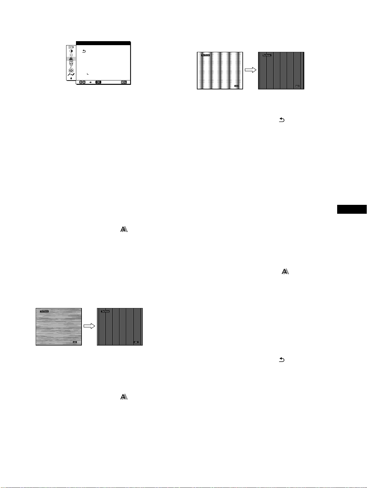
11 Press the M/m buttons until the vertical stripes
disappear.
Adjust so that the vertical stripes disappear.
12 Click [END] on the screen to turn off the test pattern.
13 Press the M/m buttons to select and press the OK
button.
Return to the menu screen.
Adjust the picture’s position manually
xxxx
(H CENTER/V CENTER)
If the picture is notin the centerof the screen, adjust the picture’s
centering as follows.
1 Set the resolution to 1280 × 1024 on the computer.
2 Load the Utility Disk.
4 Press the MENU button.
The main menu appears on the screen.
5 Press the M/m buttons to select (SCREEN) and
press the OK button.
The SCREENmenu appears on the screen.
6 Press the M/m buttons to select PHASE and press
the OK button.
The PHASE menu appears on the screen.
7 Press the M/m buttons until the horizontal stripes
are at a minimum.
Adjust so that the horizontal stripes are at a minimum.
8 Press the OK button.
The main menu appears on the screen.
If vertical stripes are observed over the entire screen, adjust
pitch by the following steps.
3 Start the Utility Disk and display the test pattern.
For Windows
[Windows]/[Win Utility.exe].
Click [Utility]
t
For Macintosh
Click [Utility]t[Mac]/[Mac Utility].
4 Press the MENU button.
The main menu appears on the screen.
5 Press the M/m buttons to select (SCREEN) and
press the OK button.
The SCREEN menu appears on the screen.
6 Press the M/m buttons to select H CENTER or
V CENTER and press the OK button.
The H CENTER or V CENTER menu appears on the screen.
7 Press the M/m buttons to center the test pattern in
the screen.
8 Click [END] on the screen to turn off the test pattern.
9 PresstheM/m buttons to select and press the OK
button.
Return to the menu screen.
US
9 Press the M/m buttons to select (SCREEN) and
press the OK button.
The SCREENmenu appears on the screen.
10 Press theM/m buttonsto select PITCHand pressthe
OK button.
The PITCH menu appears on the screen.
13
Page 14

Eliminate a shift of the picture caused by
xxxx
the automatic picture quality adjustment
(AUTO)
1 Press the MENU button.
The main menu appears on the screen.
2 Press the M/m buttons to select (SCREEN) and
press the OK button.
The SCREEN menu appears on the screen.
COLOR
You can select the picture’s color level of the white color field
from the default color temperature settings.
Also, if necessary, youcan fine tune the color temperature.
COLOR
9300K
6500K
USER
ADJUST
3 Pressthe M/m buttons to select AUTO andpress the
OK button. Then press the M/m buttons to select
OFF and press the OK button.
To resume the automatic picture quality adjustment
function
Select ON in step 3 above.
1280 1024 60Hzx/
EX I T
1 Press the MENU button.
The main menu appears on the screen.
2PresstheM/m buttons to select (COLOR) and
press the OK button.
The COLOR menu appears on the screen.
3PresstheM/m buttons to select the desired color
temperature and press the OK button.
Whites will change from a bluish hue to reddish hue as the
temperature is lowered from 9300K (default setting) to
6500K.
Fine tuning the color temperature
(USER ADJUSTMENT)
INPUT1 and INPUT2 can be set independently.
USER ADJUSTMENT
R
G
B
1280 1024 60Hzx/
50
50
50
EX I T
14
1PresstheM/m buttons to select ADJUST and press
the OK button.
The USER ADJUSTMENT menu appears on the screen.
2PresstheM/m buttons to select R (Red) or B (Blue)
and press the OK button. Then press the M/m
buttons to adjust the color temperature and press
the OK button.
Since this adjustment changes the color temperature by
increasing or decreasing theRand B components with respect
to G (green), the G component is fixed.
3PresstheM/m buttons to select ,then press the
OK button.
The new color setting is stored in memory for USER
ADJUSTMENT and automatically recalled wheneverUSER
is selected.
The COLOR menu appears on the screen.
Page 15
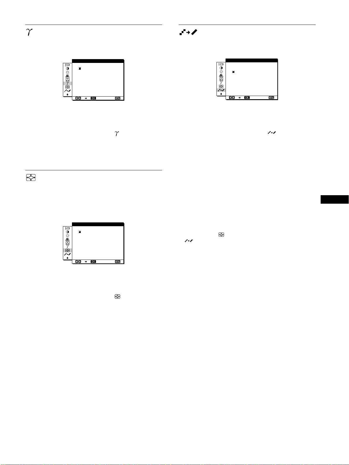
GAMMA
SMOOTHING
You canassociate the picture’scolor shade on the screen with the
picture’s original color shade.
GAMMA
GAMMA 1
GAMMA 2
GAMMA 3
1280 1024 60Hzx/
EX I T
1 Press the MENU button.
The main menu appears on the screen.
2 Press the M/m buttons to select (GAMMA) and
press the OK button.
The GAMMA menu appears on the screen.
3 Press the M/m buttons to select the desired mode.
ZOOM
The monitor is set to display the picture on the screen in full,
irrespective of the picture’s mode or resolution in the default
setting (FULL2).
You can also view the picture in its actual aspect ratio or
resolution.
ZOOM
FULL2
FULL1
REAL
1280 1024 60Hzx/
EX I T
If the picture displayed at the FULL2 or FULL1 m ode of ZOOM
is not smooth, use the picture smoothing function.
SMOOTH NGI
TEXT
STANDARD
GRAPH CS
I
1280 1024 60Hzx/
EX I T
1 Press the MENU button.
The main menu appears on the screen.
2 Press the M/m buttons to select (SMOOTHING)
and press the OK button.
The SMOOTHING menu appears on the screen.
3 Press the M/m buttons to select the desired mode.
The smoothing effect becomes stronger in the order of
TEXTtSTANDARDtGRAPHICS.
• TEXT: To makethe charact ersappear clear.(This mode is
suited for text-based applications.)
• STANDARD (The defaultsetting): Standardsmoothing
effect.
• GRAPHICS: To make the pictures appear clean. (This
mode is suited for CD-ROM software such as
photo images or illustrations.)
Notes
• When you set the (ZOOM) menu to REAL, the
(SMOOTHING) menu is not available.
• 1280 × 1024 resolution signals are shown only in REAL mode and
SMOOTHINGis not possible.
US
1 Press the MENU button.
The main menu appears on the screen.
2 Press the M/m buttons to select (ZOOM) and
press the OK button.
The ZOOM menu appears on the screen.
3 Press the M/m buttons to select the desired mode.
• FULL2 (The default setting):Theinputsignalis
displayedon the screen in full, irrespectiveof the
picture’s mode or resolution.
• FULL1:The input s ignal is displayed on the screen at its
actual aspect ratio. Therefore, black bands may
appear at the top and bottom of the picture
depending on the signal.
• REAL: The input signal is displayed on the screen at its
actual resolution. Sub-1280 × 1024 signals are
displayedat the center of the screen surrounded
by a black frame.
Note
When you use 1280 × 1024 resolution signals, the above mentioned
settings are not available. The picture is displayed on the screen in full.
15
Page 16
Additional settings
The following menus appear on the screen when you keep
pressing the m button.
• MENU POSITION
• POWER SAVE
ZZ...
• LANGUAGE
• RESET 0
• MENU LOCK
1 Press the MENU button.
The main menu appears on the screen.
2 Keeppressingthe m buttonuntil thedesired menu’s
item you want to adjust appears on the screen.
3 Press the M/m buttons to select the desired menu
and press the OK button.
Adjust the selected menu according to the following
instructions.
xxxx
MENU POSITION
You can change the menu position if it is blocking an image on
the screen.
1 Press the M/m buttons to select (MENU
POSITION) and press the OK button.
The MENU POSITION menu appears on the screen.
MENU POS T ONII
ZZ...
1280 1024 60Hzx/
EX I T
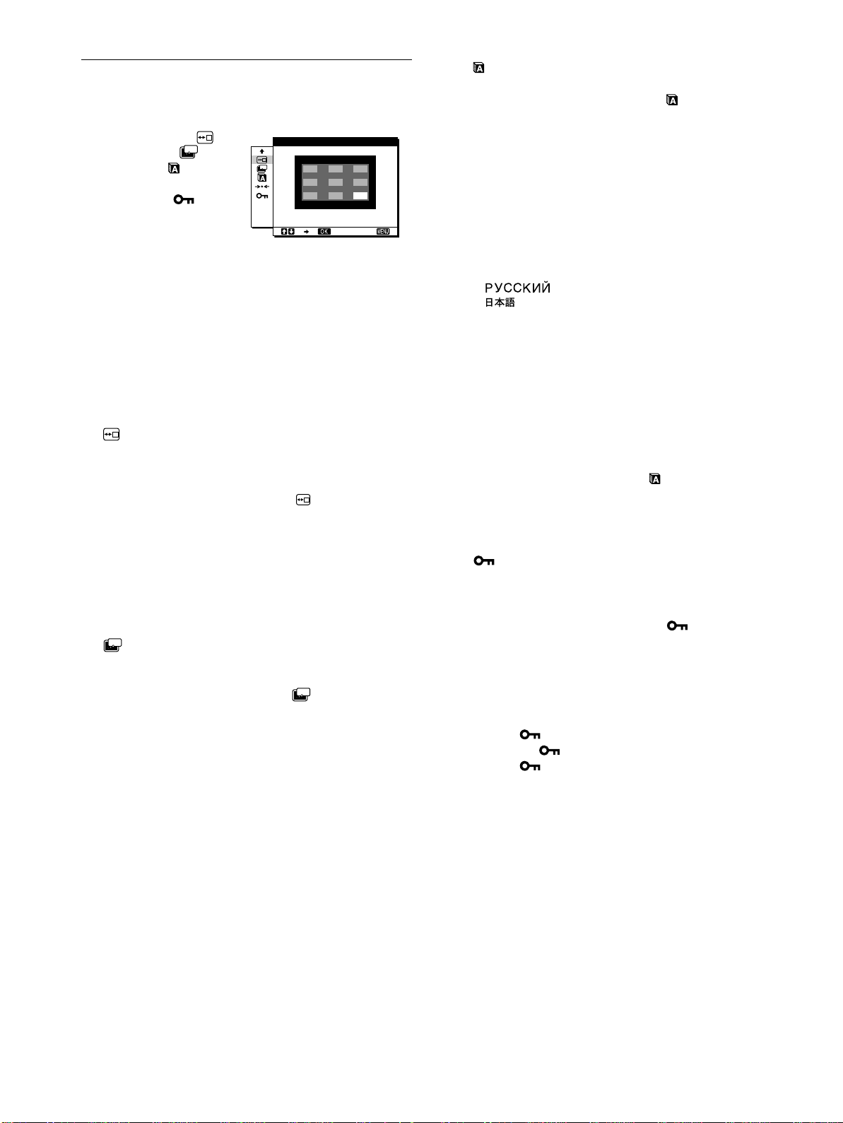
LANGUAGE
xxxx
1PresstheM/m buttons to select (LANGUAGE)
and press the OK button.
The LANGUAGE menu appears on the screen.
2PresstheM/m buttons to select a language.
• ENGLISH
• FRANÇAIS:French
• DEUTSCH:German
• ESPAÑOL:Spanish
• ITALIANO: Italian
• NEDERLANDS:Dutch
• SVENSKA:Swedish
• :Russian
• : Japanese
xxxx 0
RESET
Reset the adjustments to the default settings.
1PresstheM/m buttons to select 0 (RESET) and
press the OK button.
The RESET menu appears on the screen.
2PresstheM/m buttons to select the desired mode.
• OK: To resetall ofthe adjustment data to the default
setting. Note thatthe (LANGUAGE)setting
is not reset by this method.
• CANCEL: To cancel resetting and return to the menu
screen.
2 Pressthe M/m buttons to selectthe desired position
and press the OK button.
You can chooseone of 9 positions where the menu will
appear.
ZZ...
xxxx
POWER SAVE
Set the power saving mode (page 17).
1 Pressthe M/m buttons to select (POWER SAVE)
ZZ...
and press the OK button.
The POWER SAVE menu appears on the screen.
2 Press the M/m buttons to select either ON or OFF.
• ON: Enters the power saving mode automatically when
no input signal is being input via currently selected
computer.
• OFF: Not enter the power saving mode.
xxxx
MENU LOCK
Lock the control of buttons to prevent accidental adjustments or
resetting.
1PresstheM/m buttons to select (MENU LOCK)
and press the OK button.
The MENU LOCK menu appears on the screen.
2PresstheM/m buttons to select ON or OFF.
• ON: Only the 1 (power) switch and INPUT button will
operate. If you attempt any other operation, the
(MENU LOCK) appears on the screen.
• OFF: Set (MENU LOCK) to OFF. If you set the
(MENU LOCK) to ON, only this menu item
can be selected.
16
Page 17
Technical Features
Power saving function
This monitor meets the power-saving guidelines set by VESA,
NERGYSTAR, and NUTEK. If the monitor is connected to a
E
computer or video graphics board that is DPMS (Display Power
Management Si gnaling) compliant, the monitor will
automatically reduce power consumption as shown below.
Power mode Power consumption1(power)
normal
operation
active off*
(deep sleep)**
1 (power) off 1 W red
main poweroff 0 W off
* Whenyourcomputerentersthe“active off” mode , the input signal is
cut and NO INPUT SIGNAL appearsonthescreen. After 20seconds,
the monitor enters the power saving mode.
** “Deep sleep” is a powersaving mode defined by the Environmental
Protection Agency.
Note
ZZ...
If the (POWER SAVE) isset to OFF(page 16), the monitor does not
enter the power saving mode.
58 W (max.) green
3 W (max.) orange
Reducing the power consumpti on
(ECO mode)
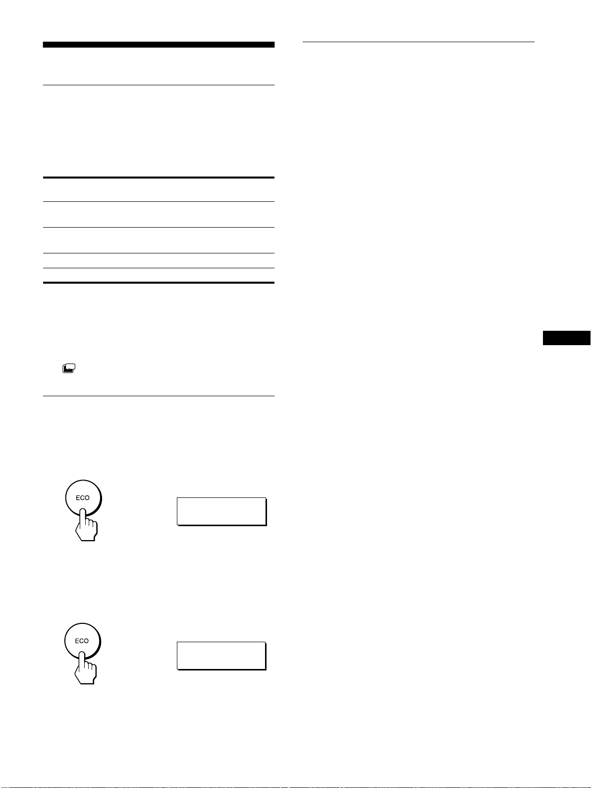
If you press the ECO button on the front of the monitor, the
backlight level reduces and the power consumption is reduced.
Press the ECO button.
,
indicator
:
ECO ON
Automatic picture quality
adjustment function
signal only)
When the monitor receives an input signal, it
automatically adjusts the picture’s position and
sharpness(phase/pitch),and ensures thata clear
picture appears on the screen.
The factory preset mode
When the monitor receives an input signal, it automatically
matches the signalto oneof the factory preset modes stored in the
monitor’s memory to provide a high quality picture at the center
of the screen. If the inputsignal matches the factory preset mode,
the picture is appears on the screen automatically with the
appropriate default adjustment.
If input signals do not match one of the factory
preset modes
When the monitor receives an input signal, the automatic picture
quality adjustment function of this monitor is activated and
ensures that a clear picture always appears on the screen (within
the following monitor frequency ranges):
Horizontal frequency:28 – 92 kHz
Vertical frequency: 56 – 85Hz
Consequently, the first time the monitor receives input signals
that do not match one of the factory preset modes, the monitor
may take a longer time than normal for displaying the picture on
the screen. This adjustment data is automatically stored in
memory so that next time, the monitor will function in the same
way as when the monitor receives the signals that match one of
the factory preset modes.
If y ou adjust the phase, pitch, and pictures
position manually
For some input signals, the automatic picture quality adjustment
function of this monitor may n ot completely adjust the picture
position,phase, and pitch.In this case, you canmanually set these
adjustments (page 12). If you manually set these adjustments,
they are stored in memory as user modes and automatically
recalled whenever the monitor receives the same input signals.
(analog RGB
US
The ECO: ON menu appears on the screen and the backlightlevel
is reduced. The menu automatically disappears after about 5
seconds.
To cancel the ECO mode
Press the ECO b uttonagain.
,
The ECO:OFF menu appearson the screen and normal backlight
level is set. The menu automatically disappears after about 5
seconds.
:
ECO OFF
17
Page 18
Troubleshooting
Before contacting technical support, refer to this section.
On-screen messages
If there is something wrong with the input signal, one of the
followingmessages appears on the screen. To solve the problem,
see “Trouble symptoms and remedies” on page 19.
If CABLE DISCONNECTED appears on the screen
This indicates that the video signal cable has been disconnected
from the currently selected connector.
INFORMATION
CAB L E D I SCONNECTED
INPUT1:DVI-D
GO TO POWER SAVE
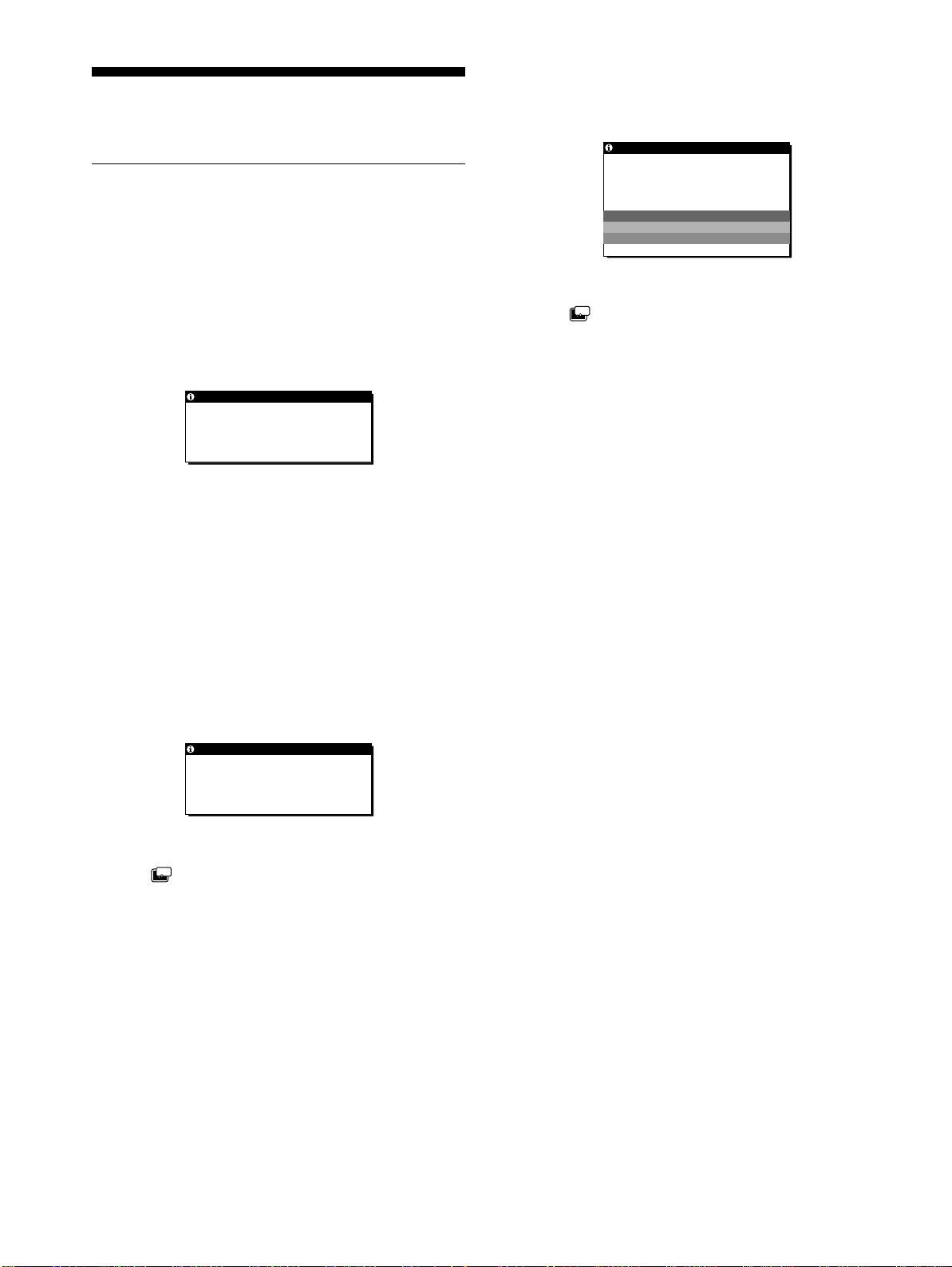
If OUT OF SCAN RANGE appears on the screen
This indicates that the input signal is not supported by the
monitor’s specifications. Check the following items.
For more information about on-screen messages, see “Trouble
symptoms and remedies” on page 19.
INFORMATION
OUT OF SCAN RANGE
INPUT1:DVI-D
xxx.xkHz/ xxx.xHz
If “xxx.x kHz/xxx Hz” is displayed
This indicates that either the horizontal or vertical frequency
is not supported by the monitor’sspecifications.
The figures indicatethe horizontaland vertical frequenciesof
the current input signal.
If “RESOLUTION > 1280 × 1024” is displayed
This indicates that the resolution is not supported by the
monitor’s specifications (1280 × 1024 or less).
If NO INPUT SIGNAL appears on the screen
This indicates that no signal is being input via the currently
selected connector.
GO TO POWER SAVE
ZZ...
If the (POWER SAVE) is set to “ON,” the monitor will
enter the power saving mode after about 5 seconds from the
time the message is displayed.
INFORMATION
NO INPUT S I GNAL
INPUT 1 :DV I - D
GO TO POWER SAVE
GO TO POWER SAVE
ZZ...
If the (POWER SAVE) is set to “ON,” the monitor will
enter the power saving mode after about 5 seconds from the
time the message is displayed.
18
Page 19

Trouble symptoms and remedies
If a problem occurs as a resultof a connected computer orother equipment, refer tothe connected computer/equipment’sinstructionmanual.
Use the self-diagnosis function (page 21) if the following recommendations do not resolve the problem.
Symptom Check these items
No picture
If the 1 (power) indicator is not lit,
or if the 1 (power) indicator will not
light up when the 1 (power) switch
is pressed,
The 1 (power) indicator turns on
red.
If the 1 (power) indicator is green, • Use the self-diagnosis function (page 21).
If CABLE DISCONNECTED
appears on the screen,
If NO INPUT SIGNAL appears on
the screen, or the 1 (power)
indicator is orange,
If OUT OF SCAN RANGE appears
on the screen (page 18),
If using Windows, • If you replaced an old monitor with this monitor, reconnect the old monitor and do the
If using a Macintosh system, • When connecting a Macintosh computer, use an adapter (not supplied) if necessary.
• Check that the power cord is properly connected.
• Check that the monitor’s MAIN POWER switch is “on” (page 9).
• Check that the 1 (power)switch is on.
• Check that the video signal cable is properly connected and all plugs are firmly seated in
their sockets (page 7).
• Check that the video input connector’s pins are not bent or pushed in.
• Check that the input select setting is correct (page 11).
• A non-supplied video signal cable is connected. If you connect a non-supplied video
signal cable, CABLE DISCONNECTED may appear on the screen before entering the
power saving mode. This is not a malfunction.
• Check that the video signal cable is properly connected and all plugs are firmly seated in
their sockets (page 7).
• Check that the video input connector’s pins are not bent or pushed in.
• Check that the input select setting is correct (page 11).
xProblem caused by a connected computer or other equipment, and not
caused by the monitor
• The computer is in the power saving mode. Try pressing any key on the keyboard or
moving the mouse.
• Check that your graphics board isattached to the computer properly.
• Check that the computer’spoweris“on.”
xProblem caused by a connected computer or other equipment, and not
caused by the monitor
• Check that the video frequency range is within that specified for the monitor. If you
replaced anold monitor with this monitor, reconnect the old monitor and adjust the
computer’s g raphics board in the following ranges:
Horizontal frequency: 28 – 92 kHz
Vertical frequency: 56 – 85 Hz
Resolution: 1280 × 1024 or less
following. Select “SONY” from the “Manufacturers” list and select “SDM-P82” from the
“Models” list in the Windows device selection screen. If “SDM-P82” does not appear in
the “Models” list, try “Plug & Play” or install the information file for this monitor using
the Windows Monitor Information Disk.
Connect the adapter to the computer beforeconnecting the video signal cable.
US
(continued)
19
Page 20

Symptom Check these items
Picture flickers, bounces,
oscillates, or is scrambled.
• Adjust the pitch and phase (analog RGB signal only) (page 12).
• Isolate and eliminate any potential sources of electric or magnetic fields such as o ther
monitors, laser printers, electric fans, fluorescent lighting, or televisions.
• Mo v e the monitor away from power lines or place a magnetic shield near themonitor.
• Try pluggingthe monitor into a different AC outlet, preferably on a different circuit.
• Change the orientation of the monitor.
xProblem caused by a connected computer or other equipment, and not
caused by the monitor
• Check your graphics board manual for the proper monitor setting.
• Confirm that the graphics mode (VESA, Macintosh 19'' Color, etc.) and the frequency of the
input signal are supported by this monitor. Even if the frequency is within the proper range,
some graphics boards may have a sync pulse that is too narrow for the monitor to sync correctly.
• This monitor does not process the interlace signals.Set for progressive signals.
• Adjust the computer’s refresh rate (vertical frequency) to obtain the best possible picture
(60 Hz is recommended).
Pictureisfuzzy. • Adjust the brightness and contrast (page 12).
• Adjust the pitch and phase (analog RGB signal only) (page 12).
xProblem caused by a connected computer or other equipment, and not
caused by the monitor
• Set the resolution to 1280 × 1024 on your computer.
Pictureisghosting. • Eliminate the use of video cable extensions and/or video switch boxes.
• Check that all plugs are firmly seated in their sockets.
Picture is not centered or sized
properly (analog RGB signal only).
• Adjust the pitch and phase (page 12).
• Adjust the picture position (page 13). Note that some video modes do not fill the screen to
the edges.
Pictureistoosmall. • Set the zoom setting to FULL2 (page 15).
xProblem caused by a connected computer or other equipment, and not
caused by the monitor
• Set the resolution to 1280 × 1024 on your computer.
Pictureisdark. • Adjust the brightness (page 12).
• Adjust the backlight (page 12).
• It takes a few minutes for the display to become bright after turning on the monitor.
• Adjust (GAMMA)(page 15).
• If you press the ECO button, the screen turns darker.
Wavy or elliptical pattern (moire)
• Adjust the pitch and phase (analog RGB signal only) (page 12).
is visible.
Color is not uniform. • Adjust the pitch and phase (analog RGB signal only) (page 12).
White does not look white. • Adjust the color temperature (page 14).
Monitor buttons do not operate
• IfthemenulockissettoON,setittoOFF(page16).
( appears on the screen).
The monitor turns off after a while. • SetthepowersavingfunctiontoOFF(page16).
xProblem caused by a connected computer or other equipment, and not
caused by the monitor
• Set the computer’s power saving setting to off.
Displaying this monitor’s name, serial number,
and date of manufacture.
While the monitor is receiving a video signal,press and
hold the MENU button for more than 5 seconds.
The monitor’s information box appears.Press the MENU button
againtomaketheboxdisappear.
Example
MENU
INFORMATION
MODEL : SDM-P82
SER. NO : 1234567
MANUFACTURED : 2002-40
Model
name
Serial
number
Week and year of
manufacture
20
If anyproblem persists, call yourauthorized Sony dealer andgive
the following information:
• Model name: SDM-P82
• Serial number
• Nameand specifications of your computer and graphics board.
• Type of input signals (analog RGB/digital RGB)
Page 21

Self-diagnosis function
Thismonitor is equippedwitha self-diagnosisfunction.Ifthere is
a problem with your monitor or computer(s), the screen will go
blank and the 1 (power) indicator will either light up green or
flash orange. If the 1 (power) indicator is lit in orange, the
computer is in power saving mode. Try pressing any key on the
keyboard or moving the mouse.
1
(power)
indicator
If the picture disappears from the screen and the
1 (power) indicator is gr een
1 Turn off the 1 (power) switch and disconnect the
video signal cables from the monitor.
2 Turn the monitor on by pressing the 1 (power)
switch.
If all four color bars appear(white, red, green, blue),the monitor
is working properly. Reconnect the video input cables and check
the condition of your computer(s).
If the colorbars donot appear, there is a potential monitorfailure.
Inform your authorized Sony dealer of the monitor’s condition.
If the 1 (power) indicator lights up in orange
Try pressing any key on the keyboard or moving the
mouse.
Thecomputer’s power saving mode isawakedand the 1 (power)
indicator lights up in green, and the pictureappears on the screen.
Specifications
LCD panel Panel type: a-Si TFT Active Matrix
Picture size: 18.1 inch
Input signal format RGB operating frequency*
Horizontal: 28 – 92 kHz
Vertical: 56 – 85 Hz
Resolution Horizontal: Max.1280 dots
Vertical: Max.1024 lines
Input signal levels Analog RGB video signal
0.7 Vp-p, 75 Ω, positive
SYNC signal
TTL level, 2.2 kΩ,
positive or negative
(Separate horizontal and vertical,
or composite sync)
0.3 Vp-p, 75Ω, negative
(Sync on green)
Digital RGB (DVI) signal: TMDS
(Single link)
Power requirements 100 – 240 V, 50 – 60 Hz,
Max. 1.2 A
Power consumption Max. 58 W
Operating temperature 5 – 35
Dimensions (width/height/depth)
Mass Approx. 7.6 kg (16 lb 12 oz) (with
Plug & Play DDC2B
Accessories See page 7.
* Recommended horizontal and vertical timing condition
• Horizontalsyncwidth duty should bemore than4.8% oftotal
horizontal time or 0.8 µs, whichever is larger.
• Horizontal blanking width should be more than 2.5 µsec.
• Vertical blanking width should be more than 450 µsec.
°C
Display (upright):
Approx. 404 × 406 × 201 mm
(16 × 16 × 8inches)
(with stand)
Approx. 404 × 332.6 × 86.2 mm
(16 × 13
(without stand)
stand)
Approx. 6.3 kg (13 lb 14 oz)
(without stand)
1
1
/8
/2 inches)
× 3
US
Design and specifications are subject to change without notice.
21
Page 22

Page 23

Table des matières
• Macintoshestune marque commerciale
sous licence d’Apple Computer, Inc.,
déposée aux Etats-Unis et dansd’autres
pays.
•Windows
déposée de Microsoft Corporation aux
Etats-Unis et dans d’autres pays.
• IBM PC/AT et VGAsont des marques
commerciales déposées d’IBM
Corporation of the U.S.A.
• VESA et DDC
commerciales de Video Electronics
StandardsAssociation.
ENERGY STAR est une marque
•
déposée aux Etats-Unis.
• Tous les autres noms de produit
mentionnés dans le présent mode
d’emploi peuvent être des marques
commercialesou des marques
commerciales déposées de leurs
entreprisesrespectives.
• De plus, les symboles “”et“”ne
sont pas systématiquement mentionnés
dans ce mode d’emploi.
estunemarquecommerciale
sont des marques
Précautions............................................4
Identification des composants et des commandes . . . . . . . . . . . . . . 5
Installation.....................................7
Réglage 1 : Raccordez un ordinateur équipé d’un connecteur de
sortieDVI(RVBnumérique).....................7
Réglage 2 : Raccordez un ordinateur équipé d’un connecteur de
sortieHD15(RVBanalogique)...................7
Réglage 3 : Branchezlecâbled’alimentation.................8
Réglage 4 : Regroupezlescordonsetlescâbles..............9
Réglage 5 : Mettez le moniteur et l’ordinateur sous tension . . . . . . 9
Réglage 6 : Réglagedel’inclinaison.......................10
Sélectiondusignald’entrée(toucheINPUT).................11
Personnalisationdevotremoniteur................11
Pilotageparmenu......................................11
RETROÉCLAIRAGE................................12
CONTRASTE.......................................12
LUMINOSITÉ......................................12
ECRAN (signal RVB analogique uniquement) . . . . . . . . . . . . . 13
COULEUR.........................................14
GAMMA...........................................15
ZOOM............................................15
SMOOTHING......................................15
Réglagesadditionnels ..................................16
Spécificationstechniques........................17
Fonctiond’économied’énergie............................17
Réduction de la consommation électrique (mode ECO). . . . . . . . . 17
Fonction de réglage automatique de la qualité de l’image
(signalRVBanalogiqueuniquement).......................18
Dépannage....................................19
Messagesaffichés.....................................19
Symptômesdedéfaillanceetremèdes......................20
Fonctiond’autodiagnostic................................22
Spécifications..................................22
TCO’99Eco-document....................................i
FR
3
Page 24

Précautions
Avertissement sur les connexions d’alimentation
• Utilisez lecâble d’alimentationfourni.Si vous utilisezun câble
d’alimentation différent, assurez-vous qu’il est compatible
avec la tension secteur locale.
Pour les clients aux Etats-Unis
Si vous n’utilisez pas le câble approprié, ce moniteur ne sera
pas conforme aux normes FCC obligatoires.
Pour les clients au Royaume-Uni
Si vous utilisez le moniteur au Royaume-Uni, veuillez utiliser
le câble d’alimentation adapté au Royaume-Uni.
Exemples de types de fiches
Remarque sur l’écran à cristaux liquides (LCD Liquid Crystal Display)
Veuillez noter que l’écran LCD est issu d’une technologie de
haute précision.Toutefois, il est possible que des points noirs ou
des points brillants de lumière (rouge, bleu ou vert)apparaissent
constamment sur l’écranLCD, ainsi que des bandes de couleurs
irrégulières ou une certaine luminosité.Ilnes’agit pas d’un
dysfonctionnement.
(Points effectifs : supérieurs à 99,99%)
Remplacement du tube fluorescent
Un tube fluorescent de conception spéciale est installé dans ce
moniteur comme source lumineuse.Si l’écran s’assombrit, est
instableou nes’allume pas, remplacez le tube fluorescent. Pourle
remplacementdu tube fluorescent, consultez votre revendeur
Sony.
pour 100 à 120 V CA pour 200 à 240 V CA pour 240 V CA
uniquement
L’appareil doit être installéàproximitéd’une prisede courant
aisément accessible.
Installation
N’installez pas et ne laissez pas le moniteur :
• A des endroits exposés à des températures extrêmes, par
exemple à proximitéd’un radiateur, d’un conduitde chauffage
ou exposé directement au soleil. L’exposition du moniteur à des
températures extrêmes, comme dans l’habitacled’une voiture
garée en plein soleil ou à proximité d’un conduit de chauffage,
risque d’entraîner des déformations du châssis ou des
dysfonctionnements.
• A des endroits soumis à des vibrations mécaniques ou à des
chocs.
• Aproximité d’appareils générant de puissants champs
magnétiques, comme un téléviseur ou d’autres appareils
électroménagers.
• A des endroit soumis à des quantités inhabituelles de poussière,
de saletés ou desable, par exemple à côté d’une fenêtre ouverte
ou d’une porte donnant sur l’extérieur. En cas d’installation
temporaire à l’extérieur, veillez à prendre les précautions
requisescontrelapoussièreetlessaletésensuspensiondansl’air.
Fautede quoi desdommages irréparablesrisquentdese produire.
Manipulation d e l’écran LCD
• Ne laissez pas l’écran LCD face au soleil, car vous risquez
sinon de l’endommager. Faites donc attention si vous installez
le moniteur à côté d’une fenêtre.
• N’appuyezpas sur la surface de l’écran LCD et veillezà ne pas
l’érafler. Ne posez pas d’objets lourds sur l’écran LCD. Vous
risquez sinon d’altérer l’uniformité de l’écran ou de provoquer
un dysfonctionnement de l’écran LCD.
• Lorsque le moniteur est utilisé dans un environnement froid, il
est possible qu’une image rémanente apparaisse sur l’écran. Il
ne s’agit pas d’un dysfonctionnement. L’écran recouvre sa
condition normale dès que la température est revenue à un
niveau normal.
• Si une image fixe reste affichée pendant une longue durée, il se
peut qu’une image rémanente apparaisse pendant un certain
temps. Cette image rémanente finira par disparaître.
• Le panneau LCD s’échauffe en cours d’utilisation. Il ne s’agit
pas d’un dysfonctionnement.
Entretien
• Débranchezle câble d’alimentationde la prise secteur avant de
procéder au nettoyage de votre moniteur.
• Net toyezl’écranLCD avec unchiffondoux. Si vousutilisezun
liquide de nettoyage pour le verre, n’utilisez pas de nettoyant
contenant une solution antistatique ou tout autre additif
similaire, car vous risquez sinon de griffer le revêtement de
l’écran LCD.
• Net toyezle châssis, le panneau et les commandesà l’aide d’un
chiffondouxlégèrement imprégné d’une solution détergente
neutre. N’utilisez aucun type de tampon abrasif, de poudre à
récurer ou de solvant tel que de l’alcool ou de la benzine.
• Ne frottez pas, ne touchez pas et ne tapotez pas la surface de
l’écran avec des objets pointus ou abrasifs comme un stylo à
bille ou un tournevis. Ce type de contact risque de rayer le tube
image.
• Sachezqu’une détériorationdesmatériauxoudurevêtement de
l’écran LCD risque de se produire si le moniteur est exposéà
des solvants volatiles comme des insecticides ou en cas de
contact prolongé avec des objets en caoutchouc ou en vinyle.
Transport
• Débrancheztous les câbles du moniteuretsaisissezle moniteur
fermement des deux mains par son support etsa base. Si vous
laissez tomber le moniteur, vous risquez de vous blesser ou
d’endommager le moniteur.
• Pour transporter ce moniteur en vue de réparations ou de son
expédition, utilisez le carton et les matériaux de
conditionnement originaux.
Elimination d u moniteur
• N’éliminez pas ce moniteur avec les ordures
ménagères.
• Le tube fluorescent utilisé dans ce moniteur contient
du mercure. L’élimination de ce moniteur doit être
effectuée conformément aux réglementations des
autoritéslocalescompétentes en matièrede propreté
publique.
4
Page 25

Identification des composants et des commandes
Pour plus de détails, reportez-vous aux pages entre parenthèses.
Avant de l’écran à cristaux liquides
Arrière du support d’écran
9
AAAA 1 Commutateur (alimentation) et 1 indicateur
(alimentation) (pages 9, 17, 22)
Ce commutateur m et le moniteur sous tension lorsque
l’indicateur d’alimentation1 s’allume en rouge. Appuyez de
nouveau sur ce commutateur pour mettre le moniteur hors
tension.
Si le voyant 1 (alimentation) ne s’allumepas, appuyezsur le
commutateur MAIN POWER (8).
BBBB Touche MENU (menu) (page 11)
Cettetouchepermetd’activer et de désactiver l’écrande
menus.
CCCC Touches M/m (page 11)
Ces touchespermettent de sélectionnerles options de menu et
d’effectuer des réglages.
Vue latérale de l’écran à cristaux liquides
DDDD Touche OK (page 11)
Cette touche active les réglages et les options de menu
sélectionnés à l’aide des touches M/m (3).
EEEE Touche INPUT et indicateur INPUT1/INPUT2
(page 11)
Cettetouchesélectionne l’ordinateur raccordé pour la
commutation des signaux d’entréevidéoetl’indicateur
correspondant (INPUT1 ou INPUT2) s’allume.
FFFF Touche AUTO (page 13)
Appuyezsurcettetouchelorsque l’imageaffichéesemblemal
réglée. L’appareil effectue un autre réglage automatique de la
qualité de l’imagepourlesignald’entrée courant.
GGGG Touche ECO (page 17)
Cettetouchepermetderéduire la consommation électrique.
HHHH Commutateur MAIN POWER (page 9)
Ce commutateur d’alimentation principal met le moniteur
sous et hors tension.
IIII Orificedeverrouillagedesécurité
L’orifice de verrouillage de sécurité doit être utilisé avec le
système Kensington Micro Saver Security System.
Micro SaverSecurity Systemest une marque commerciale de
Kensington.
FR
(suite page suivante)
5
Page 26

Arrière de l’écran à cristaux liquides
JJJJ Capot arrière (page 7)
Retirez ce capot pour raccorder des câbles ou des cordons.
qa qs qd qf
q;
KKKK Connecteur d’entrée DVI-D (RVB numérique) pour
INPUT1 (page 7)
Ce connecteur transmet des signaux vidéo RVB numériques
conformesà la DVI Rév. 1.0.
LLLL Connecteur d’entrée HD15 (RVB analogique) pour
INPUT1 (page 7)
Ce connecteur transmet des signaux vidéo RVB analogiques
(0,700 Vp-p, positifs) et des signaux SYNC.
MMMM Connecteur d’entrée HD15 (RVB analogique) pour
INPUT2 (page 7)
Ce connecteur transmet des signaux vidéo RVB analogiques
(0,700 Vp-p, positifs) et des signaux SYNC.
NNNN Connecteur AC IN (page 8)
Raccordez le cordon d’alimentation (fourni).
OOOO Cache (page 9)
Retirezce couverclepour regrouper les câbles ou les cordons
à raccorder.
PPPP Support de câbles (page 9)
Cette piéce permet de maintenir les câbles et les cordons
contre le moniteur.
qg
qh
6
Page 27

Installation
Avant d’utiliser votre moniteur, vérifiez si les accessoires
suivants se trouvent bien dans le carton d’emballage :
• Ecran LCD
• Câble d’alimentation
• Câbledesignalvidéo HD15-HD15 (RVB analogique)
• Câbledesignalvidéo DVI-D (RVB numérique)
• Windows Utility/Macintosh Utility Disk
• Cartedegarantie
• Ce mode d’emploi
Réglage 1 : Raccordez un
ordinateur équipé d’un
2
Raccordez l’ordinateur sur le c onnecteur d’entrée
DVI-D (RVB numérique) pour INPUT1 du moniteur à
l’aide du câble de signal vidéo DVI-D (RVB
numérique) fourni.
versleconnecteurd’entrée
DVI-D (RVB numérique)
pour INPUT1
connecteur de sor tie
DVI (RVB numérique)
• Eteignezlemoniteuretl’ordinateuravantd’effectuerle
raccordement.
• Lorsquevous raccordez l’ordinateur sur le connecteur
d’entrée HD15 (RVB analogique) dumoniteur,
reportez-vous à “Réglage 2 : Raccordez un ordinateur
équipé d’un connecteur de sortie HD15 (RVB
analogique)”.
Remarque
Ne touchez pas les broches du connecteur du câble de signal vidéo, car
vous risquez sinon de plier les broches.
1
Retirez le capot arrière.
vers le connecteur d’entrée
DVI (RVB numérique) de
l’ordinateur
Câble de signal vidéo
DVI-D (RVB numérique)
(fourni)
Réglage 2 : Raccordez un
ordinateur équipé d’un
connecteur de sor tie
HD15 (RVB analogique)
Eteignez le moniteur et l’ordinateur avant d’effectuer le
raccordement.
Remarque
Ne touchez pas les broches du connecteur du câble de signal vidéo, car
vous risquez sinon de plier les broches.
1
Retirez le ca pot arrière.
FR
(suite page suivante)
7
Page 28

2
Raccordez l’ordinateur sur le c onnecteur d’entrée
HD15 (RVB analogique) pour INPUT1 ou INPUT2 du
moniteur à l’aide du câbledesignalvidéo HD15HD15 (RVB analogique) fourni.
Raccordez l’ordinateur comme illustré ci-après.
Raccordement à un ordinateur IBM PC/
xxxx
AT ou compatible
versleconnecteurd’entrée
HD15 (RVB analogique)
pour INPUT1 ou INPUT2
versleconnecteurd’entrée HD15
(RVB analogique) de l’ordinateur
Réglage 3 : Branchez le câble
d’alimentation
1
Raccordez le cordon d’alimentation fourni sur le
connecteur AC IN du moniteur.
2
Raccordez-le à une prise secteur.
vers AC IN
1
vers une prise secteur
Ordinateur IBM PC/AT
ou compatible
Raccordement à un Macintosh
xxxx
versleconnecteurd’entrée
HD15 (RVB analogique)
pour INPUT1 ou INPUT2
versle connecteur de
sortie de l’ordinateur
Ordinateur Macintosh
Câble de signal vidéo
HD15-HD15 (RVB
analogique) (fourni)
Câble de signal vidéo
HD15-HD15 (RVB
analogique) (fourni)
Câble d’alimentation (fourni)
2
En cas de raccordement d’un ordinateur Macintosh, utilisez si
nécessaire un adaptateur(non fourni). Raccordezl’adaptateur sur
l’ordinateuravant de raccorder le câble du signal vidéo.
8
Page 29

Réglage 4 : Regroupez les cordons
Réglage 5 : Mettez le moniteur et
et les câbles
1
Retirez le cache.
2
Regroupez les cordons et les câbles dans le
support.
3
Fixez les câbles et les cordons à l’aide du support
de câbles.
4
Replacez le cache et le capot arrière.
1
cache
2
4
capot arrière
l’ordinateur sous
tension
1
Appuyez sur le commutateur MAIN POWER situé
sur le côté gauche du moniteur en direction de [.
L’indicateur d’alimentation 1 s’allume en rouge.
MAIN POWER
2
Appuyez sur le commutateurd’alimentation 1 situé
à droite, à l’avant du moniteur.
L’indicateur d’alimentation 1 s’allume en vert.
il s’allume en rouge
il s’allume en
vert
3
Remarque
Si vous ne parvenez pas à regrouper tous les cordons et tous les câbles
dans le support, faites-les pendre en dehors de celui-ci.
3
Mettez l’ordinateur sous tension.
4
Appuyez plusieurs fois sur la touche INPUT et
sélectionnez le signal d’entrée souhaité.
L’indicateur du signal d’entréesélectionné s’allume et
l’image apparaîtsurl’écran.
Pour plus d’informations, reportez-vous à“Sélection du
signal d’entrée(toucheINPUT)” page 11.
L’installation de votre moniteur est à présent terminée. Si
nécessaire, utilisez lescommandes du moniteur pour régler
l’image. (page 11)
FR
(suite page suivante)
9
Page 30

Si aucune image n’apparaîtsurl’écran
• Vérifiez que le câble d’alimentation et le câble du signalvidéo
sont correctement raccordés.
• Si l’indication PAS ENTREE VIDEO apparaîtsurl’écran :
– L’ordinateur est en mode d’économie d’énergie. Appuyez
sur n’importe quelle touche du clavier ou déplacez la souris.
– Vérifiez que le réglage du signal d’entrée est correct en
appuyant plusieurs fois sur la touche INPUT (page 11).
• Si CABLE PAS CONNECTÉ apparaîtsurl’écran :
– Vérifiez que le câble d’entréevidéo est branché
correctement ;
– Vérifiez que le réglage du signal d’entrée est correct en
appuyant plusieurs fois sur la touche INPUT (page 11).
• Si l’indication HORS PLAGE DE BALAYAGE apparaîtsur
l’écran, reconnectez l’ancienmoniteur. Réglez ensuite la carte
graphiquede l’ordinateur dans les plages suivantes.
Fréquence horizontale 28 – 92 kHz
Fréquence verticale 56 – 85 Hz
Résolution 1280 × 1024 ou moins
Pour des informations plus détaillées sur les messages à l’écran,
voir “Symptômes de défaillance et remèdes”àla page 20.
Réglage 6 : Réglagedel’inclinaison
Ce moniteur peut être ajusté selon les angles indiqués ci-dessous.
20°
5°
Pour une utilisation confortable du moniteur
Ajustez l’angle de visualisation de votre moniteur en fonction de
la hauteur de votre bureau et de votre chaise, pour que l’écranne
réfléchisse pas la lumière dans les yeux.
Remarque
Lors du réglage d’inclinaison de l’écran, procédez lentement et
délicatement de manière à ne pas cogner le moniteur contre le bureau ou
la base du supportd’écran.
Vous n’avez besoin d’aucun pilote pour ce moniteur
Le moniteur prend en charge la fonction Plug & Play “DDC” et détecte
automatiquement toutes les autres informationsrelatives au moniteur.Il
n’est pas nécessaire d’installer de pilote pour cet ordinateur.
Lapremièrefois que vous mettezsoustension votre ordinateuraprès avoir
raccordé le moniteur, l’assistant de réglagepeut s’afficher sur l’écran.
Dans ce cas, suivez les instructions indiquées sur l’écran. Le moniteur
Plug & Play est automatiquement sélectionné afin que vous puissiez
l’utiliser.
La fréquence verticale devient 60 Hz.
Etant donné que les scintillements sur le moniteur sont discrets, vous
pouvez l’utiliser tel quel. Vous n’avez pas besoin de régler la fréquence
verticale sur une valeurparticulièrement élevée.
1
Saisissezlapartiemédiane inférieurede l’écran à
cristaux liquides tout en maintenant le support
d’écran puis inclinez l’écran à cristauxliquides v ers
l’arrière de façon appropriée.
2
Saisissez les côtésinférieurs de l’écran à cristaux
liquides, puis ajustez l’inclinaison de l’écran.
10
Page 31

Sélection du signal d’entrée
(touche INPUT)
Appuyez sur la touche INPUT.
Le signal d’entrée change à chaque fois que vous appuyez sur
cette touche comme suit :
Personnalisation de votre moniteur
Avant de procéder aux réglages
Raccordezlemoniteur et l’ordinateur etmettez-lessoustension.
Pour obtenir les meilleurs résultats, attendez au moins
30 minutes avant d’effectuerles réglages.
Vous pouvez effectuer de nombreux réglages l’aide des menus
d’affichage.
Message à
l’écran
(apparaîtdansles
5 secondes dans le
coin supérieur
gauche).
ENTRÉE1
(INPUT1): DVI-D
ENTRÉE1
(INPUT1): HD15
ENTRÉE2
(INPUT2): HD15
L’indicateur
d’entrée
s’allume
INPUT1 Connecteur d’entree
INPUT1 Connecteur d’entree
INPUT2 Connecteur d’entree
Configuration du
signal d’entrée
DVI-D(RVB numérique)
pour INPUT1
HD15 (RVBanalogique)
pour INPUT1
HD15 (RVBanalogique)
pour INPUT2
Pilotage par menu
1
Affichez le menu principal.
Appuyez surla toucheMENUpour afficher lemenu principal
sur votre écran.
MENU
2
Sélectionnez le menu que vous voulez régler.
Appuyez sur les touches M/m pour afficher lemenu de votre
choix. Appuyez sur la touche OK pour sélectionner un
élément de ce menu.
OK
,
3
Réglez le menu.
Appuyez sur les touches M/m pour effectuervotre réglage
puis appuyez sur la touche OK.
Lorsque vous appuyez sur OK, le réglage est mémorisé et
l’appareil revient au menu précédent.
FR
,
OK
(suite page suivante)
11
Page 32

4
Quittez le menu.
Appuyez une fois sur la touche MENU pour reveniren mode
de visualisation normale. Si vous n’actionnez aucune touche,
le menu se referme automatiquement au bout d’environ
45 secondes.
MENU
CONTRASTE
Ajustez le contraste de l’image.
CONTRAS T E
100
Réinitialisation des réglages aux réglages
xxxx
par défaut
Vous pouvez réinitialiser les réglages à l’aide du menu
RESTAUR. Pour plus d’informations sur la réinitialisation des
réglages, reportez-vous à“0 (RESTAUR)” page 16.
RETROÉCLAIRAGE
Si l’écran est trop lumineux, ajustez le rétroéclairage pour rendre
l’écran plus facile à regarder.
Remarque
Il est impossible d’ajuster le rétroéclairage lorsque le mode ECO est réglé
sur “ACTIF” (page 17).
RETROÉCL A RAGEI
100
1280 1024 60Hzx/
1
Appuyez sur la touche MENU.
Le menu principal apparaîtsurl’écran.
2
Appuyez sur les touches M/m pour sélectionner
(RETROÉCLAIRAGE) puis appuyez sur la
touche OK.
Le menu RETROÉCLAIRAGE apparaîtsurl’écran.
EX I T
1280 1024 60Hzx/
1
Appuyez sur la touche MENU.
EX I T
Le menu principal apparaîtsurl’écran.
2
Appuyez sur les touches M/m pour sélectionner
6 (CONTRASTE) puis appuyez sur la touche OK.
Le menu CONTRASTE apparaîtsurl’écran.
3
Appuyez sur les touches M/m pour régler le
contraste.
LUMINOSITÉ
Ajustez la luminosité de l’image (niveau du noir).
LUM NOS TÉII
100
1280 1024 60Hzx/
1
Appuyez sur la touche MENU.
Le menu principal apparaîtsurl’écran.
2
Appuyez sur les touches M/m pour sélectionner
8 (LUMINOSITÉ) puis appuyez sur la touche OK.
Le menu LUMINOSITÉ apparaîtsurl’écran.
3
Appuyez sur lestouchesM/mpour réglerla luminosité.
EX I T
3
Appuyez sur les touches M/m pour ajusterle niveau
de luminosité souhaité.
12
Page 33

ECRAN
(signal RVB analogique
uniquement)
Remarque
Lorsque vous recevez dessignaux RVB numériques depuis leconnecteur
d’entrée DVI-D pour INPUT1, aucun réglage n’est nécessaire.
Fonction de réglage automatique de la
xxxx
qualité de l’image
Lorsque le moniteur reçoit un signal d’entrée, il
ajuste automatiquement la position et la netteté
del’image (phase/horloge) etgarantit la qualitéde
l’image qui apparaîtsurl’écran (page 18).
3
Démarrez la disquette d’utilitaire et affichez la mire
de test.
Pour Windows
Cliquez sur [Utility]
Pour Macintosh
Cliquez sur [Utility] t
4
Appuyez sur la touche MENU.
Le menu principal apparaîtsurl’écran.
5
Appuyez sur les touches M/m pour sélectionner
(ECRAN) puis appuyez sur la touche OK.
Le menu ECRAN apparaîtsurl’écran.
6
Appuyez sur les touches M/m pour sélectionner
PHASE puis appuyez sur la touche OK.
Le menu PHASE apparaîtsurl’écran.
t [Windows]/[Win Utility.exe].
[Mac]/[Mac Utility].
Remarque
Lorsquelafonctionderéglage automatique de la qualité de l’image est
activée, seul le commutateur d’alimentation
Si la fonction de réglage automatique de la qualité de
l’imagedecemoniteursemblenepasrégler
complètement l’image.
Vous pouvez effectuer un autre réglage automatique de la qualitéde
l’imagepourlesignald’entrée courant en appuyant sur la touche
AUTO (page 5).
Si vous souhaitez effectuer d’autres réglages de la
qualité de l’image
Vous pouvez régler manuellement la netteté (phase/horloge)et la
position (horizontale/verticale) de l’image.
Si vous avez besoin de supprimer un décalage de
l’image se produisant lorsque le signal d’entréea
changé
Le décalage est causé parlafonctionderéglageautomatiquede la
qualité de l’image. Vous pouvez désactiver cette fonction
(page 14).
Ces réglages sont mémorisés et automatiquement rappelés
lorsquelemême signal d’entréeestreçu.
ECRAN
PHASE
P I TCH
CENTRAGE H
CENTRAGE V
AUTOMAT QUE
ACTIF
1280 1024 60Hzx/
I
EX I T
fonctionne.
1
7
Appuyez sur les touches M/m jusqu’à ce que les
bandes horizontales soient réduites au minimum.
Réglez la valeur de façon à ce que les rayures horizontales
soient réduites au minimum.
8
Appuyez sur la touche OK.
Le menu principal apparaîtsurl’écran.
Si vous observez des bandes verticales sur tout l’écran,
ajustez le pas en suivant les étapes suivantes.
9
Appuyez sur les touches M/m pour sélectionner
(ECRAN) puis appuyez sur la touche OK.
Le menu ECRAN apparaîtsurl’écran.
10
Appuyez sur les touches M/m pour sélectionner
PITCH puis appuyez sur la touche OK.
Le menu PITCHapparaîtsurl’écran.
11
Appuyez sur les touches M/m jusqu’à ce que les
bandes verticales disparaissent.
Ajustezlavaleurjusqu’à ce que les rayures verticales aient
disparu.
FR
Réglagemanueldelanetteté de l’image
xxxx
(PHASE/PITCH)
Vous pouvez ajusterla netteté de l’image comme suit. Ce réglage
est effectif lorsque l’ordinateur est raccordé sur le connecteur
d’entrée HD15 (RVB analogique) du moniteur.
1
Réglez la résolution de l’ordinateur sur 1280 × 1024.
2
Chargez la disquette d’utilitaire.
12
Cliquez sur [END] à l’écran pour désactiver la mire
de test.
13
Appuyez sur les touches M/m pour sélectionner
puis appuyez sur la touche OK.
L’écran des menus s’affiche à nouveau.
13
Page 34

Réglagemanueldelapositiondel’image
xxxx
(CENTRAGE H/CENTRAGE V)
Si l’image n’est pas centréesurl’écran, ajustez le centrage de
l’image en procédant comme suit :
1
Réglez la résolution de l’ordinateur sur 1280 × 1024.
2
Chargez la disquette d’utilitaire.
3
Démarrez la disquette d’utilitaire et affichez la mire
de test.
Pour Windows
Cliquez sur [Utility]
t [Windows]/[Win Utility.exe].
Pour Macintosh
[Mac]/[Mac Utility].
Cliquez sur [Utility]
4
Appuyez sur la touche MENU.
t
Le menu principal apparaîtsurl’écran.
5
Appuyez sur les touches M/m pour sélectionner
(ECRAN) puis appuyez sur la touche OK.
Le menu ECRAN apparaîtsurl’écran.
6
Appuyez sur les touches M/m pour sélectionner
CENTRAGE H ou CENTRAGE V puis appuyez sur la
touche OK.
Le menu CENTRAGEH ouCENTRAGE V apparaîtsur l’écran.
7
Appuyez sur la touche M/m pour centrer la mire de
test sur l’écran.
8
Cliquez sur [END] à l’écran pour désactiver la mire
de test.
9
Appuyez sur les touches M/m pour sélectionner
puis appuyez sur la touche OK.
L’écran des menus s’affiche à nouveau.
Suppression d’un décalage de l’image dû
xxxx
au réglage automatique de la qualité de
l’image (AUTOMATIQUE)
1
Appuyez sur la touche MENU.
Le menu principal apparaîtsurl’écran.
COULEUR
Vous pouvez sélectionner le niveau de couleur deszones de
couleur blanche de l’image à l’aide des réglages de température
des couleurs par défaut.
Vous pouvez également régler avec précision la température des
couleurs, si nécessaire.
COULEUR
9300K
6500K
UT I L I SAT EUR
RÉGLER
1280 1024 60Hzx/
1
Appuyez sur la touche MENU.
Le menu principal apparaîtsurl’écran.
2
Appuyez sur les touches M/m pour sélectionner
(COULEUR) puis appuyez sur la touche OK.
Le menu COULEUR apparaît à l’écran.
3
Appuyez sur les touches M/m pour sélectionner la
températuredes couleursde votre choix et appuyez
ensuite sur la touche OK.
Les blancs passent d’uneteintebleuâtre àune teinte rougeâtre
lorsque la température passe de 9300K (réglage par défaut) à
6500K.
Réglage précisdelatempérature des couleurs
(RÉGLER UTILISA)
Ilestimpossiblederégler INPUT1 et INPUT2 séparément.
RÉGLER UTILISA
R
G
B
1280 1024 60Hzx/
1
Appuyez sur les touches M/m pour sélectionner
RÉGLER puis appuyez sur la touche OK.
Le menu RÉGLER UTILISA apparaît à l’écran.
EX I T
50
50
50
EX I T
2
Appuyez sur les touches M/m pour sélectionner
(ECRAN), puis appuyez sur la touche OK.
Le menu ECRAN apparaîtsurl’écran.
3
Appuyez sur les touches M/m pour sélectionner
AUTOMATIQUE, puis appuyez sur la touche OK.
Appuyez ensuite sur les touches M/m pour
sélectionner INACTIF et appuyez sur la touche O K.
Pour réactiverla fonction de réglage automatiquede la
qualité de l’image
Sélectionnez ACTIF à l’étape 3 ci-dessus.
14
2
Appuyez sur les touches M/m pour sélectionner
R (rouge) ou B (bleu) puis appuyez sur la touche
OK. Appuyez ensuite sur les touches M/m pour
ajuster la température des couleurs, puis appuyez
sur la touche OK.
Etant donné queceréglagemodifielatempérature des
couleurs en augmentant ouen diminuant les composantes Ret
B par rapport à V (vert), la composante V est fixe.
3
Appuyez sur les touches M/m pour sélectionner ,
puis appuyez sur la touche OK.
Le nouveau réglage des couleursde RÉGLER UTILISA est
enregistrédans la mémoire et automatiquement rappelé
lorsque UTILISATEUR est sélectionné.
Le menu COULEUR apparaîtsurl’écran.
Page 35

GAMMA
Vous pouvez associer les nuances foncées des couleurs del’image
affichée à l’écran à celles des couleurs originalesde l’image.
GAMMA
GAMMA 1
GAMMA 2
GAMMA 3
1280 1024 60Hzx/
1
Appuyez sur la touche MENU.
EX I T
Le menu principalapparaît à l’écran.
2
Appuyez sur les touches M/m pour sélectionner
(GAMMA) puis appuyez sur OK.
Le menu GAMMA apparaît à l’écran.
3
Appuyez sur les touches M/m pour sélectionner le
mode souhaité.
ZOOM
Le moniteur est réglé pour afficher l’image en plein écran, quel
quesoitlemodeoularésolution de l’image dans le réglage par
défaut (FULL2).
Vous pouvez également visualiser l’image dans son formatou sa
résolution réels.
ZOOM
FULL2
FULL1
ORIGI NAL
Remarque
Lorsquevous utilisez les signaux de résolution 1280 × 1024, les réglages
mentionnés ci-dessus ne sont pas disponibles.L’image s’affiche en plein
écran.
SMOOTHING
Si l’image affichée en mode FULL2 ou FULL1 de la fonction
ZOOM n’est pas lisse, utilisez la fonction de lissage de l’image.
SMOOTH NGI
TEXTE
STANDARD
I
GRAPH QUE
1280 1024 60Hzx/
1
Appuyez sur la touche MENU.
Le menu principal apparaîtsurl’écran.
2
Appuyez sur les touches M/m pour sélectionner
(SMOOTHING), puis sur OK.
Le menu SMOOTHING apparaîtsurl’écran.
3
Appuyez sur les touches M/m pour sélectionner le
mode souhaité.
L’effet de lissage est plus visible dans ce sens :
TEXTEtSTANDARDtGRAPHIQUE.
• TEXTE : Caractère en clair. (Ce mode convient aux
applications de traitement de texte.)
• STANDARD (réglage par défaut) : Effet de lissage
standard.
• GRAPHIQUE : Images nettes. (Ce mode convient aux
CD-ROM contenant des photos ou des
illustrations.)
EX I T
FR
1280 1024 60Hzx/
1
Appuyez sur la touche MENU.
EX I T
Le menu principalapparaîtsurl’écran.
2
Appuyez sur les touches M/m pour sélectionner
(ZOOM), puis appuyez sur OK.
Le menu ZOOM apparaîtsurl’écran.
3
Appuyez sur les touches M/m pour sélectionner le
mode souhaité.
• FULL2 (réglage par défaut) :Lesignald’entrée
s’affiche en pleinécran, quel quesoit le mode ou
la résolution de l’image.
• FULL1 :Lesignald’entrées’affiche sur l’écran en
fonction du rapport hauteur/largeuren cours. Par
conséquent, des bandes noires peuvent
apparaîtreenhautetenbasdel’image, selon le
signal.
• ORIGINAL :Lesignald’entrées’affiche sur l’écran en
fonctiondelarésolution en cours. Les signaux
sous-1280 × 1024 sont affichés au centre de
l’écran entourésd’un cadre noir.
Remarques
• Lorsque vous réglez le menu (ZOOM) sur ORIGINAL, le m enu
(SMOOTHING) n’est pas disponible.
• Les signaux de résolution 1280 × 1024 sont uniquement affichésen
mode ORIGINAL et la fonction SMOOTHING est inactive.
15
Page 36

Réglages additionnels
Les menus suivants apparaissent sur l’écran lorsque vous
maintenez la touche m enfoncée.
• POSITION MENU
• MODE ÉCO
• LANGUAGE
• RESTAURE 0
• VERROU RÉGLAGES
1
Appuyez sur la touche MENU.
Le menu principal apparaîtsurl’écran.
2
Maintenez la touche m enfoncée jusqu’à ce que
l’option de menu que vous souhaitez régler
apparaisse sur l’écran.
3
Appuyez sur les touchesM/mpour sélectionner
l’option de menu de votre choix, puis appuyez sur OK.
Réglez l’option de menu sélectionnée en appliquant les
instructions suivantes.
xxxx
Vous pouvez changer la position du menu s’il masqueune image
à l’écran.
1
2
xxxx
Réglez le mode d’économie d’énergie (page 17).
1
2
POSITION MENU
Appuyez sur les touches M/m pour sélectionner
(POSITION MENU) puis a ppuyez sur la touche
OK.
Le menu POSITION MENU apparaîtsurl’écran.
Appuyez sur les touches M/m pour sélectionner la
position souhaitée puis appuyez sur la touche OK.
Vous pouvez choisir l’une des 9 positions pour l’affichage du menu.
ZZ...
Appuyez sur les touches M/m pour sélectionner
ZZ...
Le menu MODE ÉCO apparaîtsurl’écran.
Appuyez sur les touches M/m pour sélectionner
ACTIF ou INACTIF.
• ACTIF : passe automatiquement en mode d’économie
• INACTIF : ne passe pas en mode d’économie d’énergie.
ZZ...
MODE ÉCO
(MODE ÉCO), puis appuyez sur la touche OK.
d’énergie lorsqu’aucun signal d’entréen’est reçu
via l’ordinateur sélectionné.
POS T ON MENUII
ZZ...
1280 1024 60Hzx/
EX I T
LANGUAGE
xxxx
1
Appuyez sur les touches M/m pour sélectionner
(LANGUAGE) puis appuyez sur la touche OK.
Le menu LANGUAGE apparaîtsurl’écran.
2
Appuyez sur les touchesM/m pour sélectionner une
langue.
• ENGLISH : Anglais
• FRANÇAIS
• DEUTSCH :Allemand
• ESPAÑOL :Espagnol
• ITALIANO : Italien
• NEDERLANDS :Néerlandais
• SVENSKA :Suédois
• :Russe
• :Japonais
xxxx 0
Réinitialisation des réglages aux valeurs par défaut.
1
2
xxxx
Verrouillezla commande destouchesafin d’éviter tout réglageou
toute réinitialisation accidentels.
1
2
RESTAURE
Appuyez sur les touches M/m pour sélectionner
0 (RESTAURE) puis appuyez sur la touche OK.
Le menu RESTAURE apparaîtsurl’écran.
Appuyez sur les touches M/m pour sélectionner le
mode souhaité.
• OK :Réinitialise toutes les données de réglage à la
configuration par défaut. Notez que le réglage
(LANGUAGE) n’est pas réinitialisé par cette
méthode.
• ANNULER: Annule laréinitialisationet retourne àl’écran
du menu.
VERROU RÉGLAGES
Appuyez sur les touches M/m pour sélectionner
(VERROU RÉGLAGES) puis appuyez sur la
touche OK.
Le menu VERROU RÉGLAGES apparaîtsurl’écran.
Appuyez sur les touches M/m pour sélectionner
ACTIF ou INACTIF.
• ACTIF : seuls le commutateur d’alimentation 1 et la
touche INPUT sont actifs. Si vous essayez
d’activer une autre touche, (VERROU
RÉGLAGES) apparaîtsurl’écran.
• INACTIF : (VERROU RÉGLAGES) est désactivé.Si
vous réglez le (VERROURÉGLAGES) sur
ACTIF, seul ce paramètredemenupeutêtre
sélectionné.
16
Page 37

Spécifications techniques
Réduction de la consommation
électrique
(mode ECO)
Fonction d’économie d’énergie
Ce moniteur satisfait aux critères d’économie d’énergie VESA,
NERGYSTAR et NUTEK. Lorsque le moniteurest raccordéà
E
un ordinateurou une carte graphique vidéo compatible DPMS
(Display Power Management Signaling), le moniteur réduit
automatiquement sa consommation d’énergie comme indiqué cidessous.
Mode
d’alimentation
fonctionnement
normal
inactif*
(sommeil profond)**
1 (alimentation)
inactif
Alimentation
principale inactive
* Lorsque votre ordinateur passe enmode “inactif”, le signal d’entrée
est coupé et l’indication PAS ENTREE VIDEO apparaît à l’écran.Au
bout de 20 secondes, le moniteur passe en mode d’économie
d’énergie.
** “Sommeil profond” est un mode d’économie d’énergie défini par
l’Environmental Protection Agency.
Consommation
d’énergie
58 W (max.) v ert
3 W (max.) orange
1 W rouge
0W désactivé
L’indicateur 1
(alimentation)
Si vous appuyez sur la touche ECO située à l’avant du moniteur,
le niveau du rétroéclairage est réduit, ainsi que la consommation
électrique.
Appuyez sur la touche ECO.
,
Le menu ECO: ACTIF s’afficheet le niveaudu rétroéclairage est
réduit. Le menu disparaît automatiquement aprèsenviron5
secondes.
Pour annuler le mode ECO
Appuyez de nouveau sur la touche ECO.
,
Le menu ECO: INACTIF s’affiche et le niveau normal du
rétroéclairage est réglé.Lemenudisparaît automatiquementaprès
environ 5 secondes.
:
ECO A CT I F
:
ECO I NACT I F
FR
Remarque
ZZ...
Si (MODE ÉCO) est réglé sur INACTIF (page 16), le moniteur ne
passe pas en moded’économie d’énergie.
17
Page 38

Fonction de réglage automatique
de la qualité de l’image
(signal RVB
analogique uniquement)
Lorsque le moniteur reçoit un signal d’entrée, il
ajuste automatiquement la position et la netteté
del’image(phase/horloge) et garantit laqualitéde
l’image qui apparaîtsurl’écran.
Le mode préréglé en usine
Lorsque le moniteur reçoit un signal d’entrée, il fait
automatiquement correspondrele signal à l’un des modes
présélectionnéspardéfaut enregistrésdanslamémoire du
moniteurafin deproduire u ne image de haute qualité au centre de
l’écran. Si lesignal d’entrée correspondaumode préréglé d’usine,
l’image apparaîtautomatiquementsur l’écran,avec le réglage par
défaut approprié.
Si certains signaux d’entrée ne correspondent à
aucun mode préréglé d’usine
Lorsque le moniteur reçoit un signal d’entrée, la fonction de
réglage automatique de la qualité de l’imagedecemoniteurest
activée et garantitl’affichage permanentd’une image claire sur
l’écran (dans les plages de fréquences suivantes du moniteur) :
Fréquence horizontale : 28 – 92 kHz
Fréquence verticale : 56 – 85 Hz
En conséquence, la première fois que le moniteur reçoitdes
signaux d’entrée qui ne correspondent pas à l’un desmodes
présélectionnéspardéfaut, il se peut que le moniteur prenne un
peu plus de tempsque d ’habitude pour afficher l’image à l’écran.
Ces données de réglagessont automatiquementenregistrées dans
la mémoire de sorte que le moniteur fonctionnera de la même
manière la prochainefois qu’il recevra des signaux correspondant
à l’un des modesprésélectionnéspardéfaut .
Si vous ajustez la phase, le pas et la position des
images manuellement
Pour certains signaux d’entrée, la fonction de réglage
automatiquedelaqualité de l’image de ce moniteur peut ne pas
ajuster totalementla position, la phase et le pas de l’image. Dans
ce cas, vous pouvez effectuer ces réglages manuellement
(page 13). Si vous effectuez ces réglages manuellement, ils sont
mémorisés comme des modes utilisateurs et sont
automatiquement rappelés lorsque le moniteur reçoit les mêmes
signaux d’entrée.
18
Page 39

Dépannage
Avant de prendre contact avec l’assistance technique,consultez
les informations présentées dans cette section.
Messages affichés
S’il se produit une anomalieau niveaudu signal d’entrée, l’un des
messages suivants apparaîtsurl’écran. Pour résoudre le
problème,voir “Symptômes de défaillance et remèdes”àla
page 20.
Si l’indication CABLE PAS CONNECTÉ apparaît
sur l’écran
Cela signifie que le câbledesignalvidéoaété déconnecté du
connecteur actuellement sélectionné.
INFORMATI
CAB L E PAS CONNECTÉ
ENTRÉE1 : D
PASSER EN M DOEÉCO
ON
S
VI-D
Si l’indication HORS PLAGE DE BALAYAGE
apparaîtsurl’écran
Cela signifie quele signald’entréen’est pas pris en charge par les
spécifications du moniteur. Vérifiez les éléments suivants.
Pour des informations plus détaillées sur les messages à l’écran,
voir “Symptômes de défaillance et remèdes”àla page 20.
INFORMATI
HORS PLAGE DE
BAL AYAGE
ENTRÉE1 : DV I - D
xxx.xkHz/ xxxHz
ONS
Si “xxx.x kHz/xxx Hz” est affiché
Cela signifie que la fréquence horizontale ou verticale n’est
pas prise en charge par les spécifications du moniteur.
Les chiffres indiquent les fréquences horizontales et
verticales du signal d’entréeencours.
Si “RESOLUTION > 1280 × 1024” est affiché
Celasignifie que larésolutionn’estpaspriseenchargeparles
spécifications du moniteur (1280 × 1024 ou moins).
Si l’indication PAS ENTREE VIDEO apparaîtsur
l’écran
Cela signifie qu’aucun signal n’est détecté en entrée via le
connecteur actuellement sélectionné.
PASSER EN MODE ÉCO
ZZ...
Si (MODE ÉCO) est réglé sur “ACTIF”, le moniteur
passe en mode d’économie d’énergie environ 5 secondes
aprèsl’affichage du message.
FR
INFORMATION
PAS ENTREE V I DEO
ENTRÉE1 : DV I - D
PASSER EN MODE ÉCO
S
PASSER EN MODE ÉCO
ZZ...
Si (MODE ÉCO) est réglé sur “ACTIF”, le moniteur
passe en mode d’économie d’énergie environ 5 secondes
aprèsl’affichage du message.
19
Page 40

Symptômes de défaillance et remèdes
Si un problèmeest causé par un ordinateur ou unautre appareil raccordé, reportez-vous aux modes d’emploi de l’appareiloude l’ordinateur
concerné.
Utilisez la fonction d’autodiagnostic(page 22) si les recommandations suivantes n e permettent pas de résoudre le problème.
Symptôme Vérifiez ces éléments
Pas d’image
Si l’indicateur1(alimentation) n’est pas
alluméou sil’indicateur
ne s’allume pas lorsque vous appuyez sur
le commutateur
L’indicateur d’alimentation 1
devient rouge.
Si le voyant1(alimentation) est vert
Si CABLE PAS CONNECTÉ
apparaîtsurl’écran,
Si l’indication PAS ENTREE
VIDEO s’affiche à l’écran ou si le
voyant 1 (alimentation) est orange,
Si l’indication HORS PLAGE DE
BALAYAGE apparaîtsurl’écran
(page 19),
Si vous utilisez Windows, • Si vous avez remplacé votre ancien moniteur par ce moniteur, rebranchez l’ancien
Si vous utilisez un système
Macintosh,
L’image scintille, sautille, oscille
ou est brouillée.
1
(alimentation)
1
(alimentation),
• Vérifiez si le câble d’alimentation est correctement raccordé.
• Vérifiez que le commutateur MAIN POWER est réglé sur “ON” (page 9).
• Vérifiez que le commutateur 1 (alimentation) est activé.
• Utilisez la fonction d’autodiagnostic(page 22).
• Vérifiez si le câbledesignalvidéo est correctement raccordé et si toutes les fiches sont
correctement branchées sur leur prise (page 7).
• Vérifiez si les broches du connecteur d’entréevidéo ne sont pas pliées ou enfoncées.
• Vérifiez si le réglagedesélection d’entrée est correct (page 11).
• Un câbledesignalvidéo non fourni est connecté. Si vous raccordez un câble de vidéonon
fourni, l’indication CABLE PAS CONNECTÉ apparaîtsurl’écran avant le passage au
mode d’économie d’énergie. Il ne s’agit pas d’un dysfonctionnement.
• Vérifiez si le câbledesignalvidéo est correctement raccordé et si toutes les fiches sont
correctement branchées sur leur prise (page 7).
• Vérifiez si les broches du connecteur d’entréevidéo ne sont pas pliées ou enfoncées.
• Vérifiez si le réglagedesélection d’entrée est correct (page 11).
Problème causé par un ordinateurou un autre appareil raccordé et non par le moniteur
x
• L’ordinateur se trouve en mode d’économie d’énergie. Appuyez sur une touche
quelconque du clavier ou déplacez la souris.
• Vérifiez que votre carte graphique est correctement connectée à votre ordinateur.
• Vérifiez si l’alimentation de l’ordinateur est régléesur“ON”.
Problème causé par un ordinateurou un autre appareil raccordé et non par le moniteur
x
• Vérifiez si la plage de fréquence vidéo est comprise dans la plage spécifiéepourle
moniteur. Si vous avez remplacé un ancien moniteur par ce moniteur, rebranchez l’ancien
puisajustezlacartegraphiquedel’ordinateurdans les plages suivantes.
Fréquence horizontale : 28 – 92 kHz
Fréquence verticale : 56 – 85 Hz
Résolution : 1280 × 1024 ou moins
moniteur et suivez la procédure suivante. Sélectionnez “SONY” dans la liste “Fabricants”
et sélectionnez “SDM-P82” dans la liste “Modèles” de l’écran de sélection des
périphériquesde Windows.Si “SDM-P82” n’apparaît pas dans la liste “Modèles”, essayez
“Plug & Play” ou installez le fichier d’information de ce moniteur à l’aide de Windows
Monitor Information Disk.
• En cas de raccordement d’un ordinateur Macintosh, utilisez si nécessaire un adaptateur
(non fourni). Raccordez l’adaptateur sur l’ordinateur avant de raccorder le câble du signal
vidéo.
• Réglez l’horloge et la phase (signal RVBanalogique uniquement) (page 13).
• Isolez et supprimez les sourcespotenti elles de champs électriques ou magnétiques telles
que d’autres moniteurs, des imprimantes laser, des ventilateurs électriques, des éclairages
fluorescents ou des téléviseurs.
• Eloignez le moniteur des lignes à haute tension ou placez un blindage magnétique à
proximité du moniteur.
• Branchez le moniteur sur une autre prise secteur ,de préférence reliée à un autre circuit.
• Changez l’orientation de l’écran.
Problème causé par un ordinateurou un autre appareil raccordé et non par le moniteur
x
• Consultez le mode d’emploi de votre carte graphique pour le réglage approprié du moniteur.
• Assurez-vous que le mode graphique (VESA, Macintosh 19" Color, etc.) et la fréquencedu
signal d’entrée sont supportés par ce moniteur. Même si la fréquence est comprise dans la
plage appropriée, il sepeut que certaines cartes vidéo offrentune impulsion de
synchronisationtrop étroite pour que le moniteur se synchronise correctement.
• Ce moniteur ne traite pas les signaux entrelacés. Utilisez des signaux progressifs.
• Ajustezletauxderégénération de l’ordinateur (fréquence verticale) de manière à obtenir
la meilleure image possible (60 Hz est recommandé).
20
Page 41

Symptôme Vérifiez ces éléments
L’image est floue. • Réglez la luminosité et le contraste (page 12).
• Réglez le pas et la phase (signal RVB analogique uniquement) (page 13).
Problème causé par un ordinateur ou un autre appareil raccordéet non parle moniteur
x
• Réglez la résolution de votre ordinateur sur 1280 × 1024.
Apparition d’images fantômes. • N’utilisez pas de prolongateurs de câble vidéo et/ou de boîtiers de commutation vidéo.
• Vérifiez si toutes les fiches sont correctement br anchées sur leur prise.
L’image n’est pas centrée
correctement, ni du bon format
(signal RVBanalogique uniquement).
• Réglez le pas et la phase (page 13).
• Ajustez la position de l’image (page 14). Notez que certains modes vidéo ne remplissent
pas l’écran jusqu’aux bords.
L’image est trop petite. • Réglez le paramètre zoom sur FULL2 (page 15).
Problème causé par un ordinateur ou un autre appareil raccordéet non parle moniteur
x
• Réglez la résolution de votre ordinateur sur 1280 × 1024.
L’image est sombre. • Réglez la luminosité (page 12).
• Réglez le rétroéclairage (page 12).
• Plusieurs minutes sont nécessaires avant que l’écran ne devienne lumineux aprèssamise
sous tension.
• Réglez (GAMMA) (page 15).
• L’écran devient plus sombre lorsque vous appuyez sur la touche ECO.
Apparition d’un motif ondulatoire
• Ajustez l’horloge et la phase (signal RVB analogique uniquement) (page 13).
ou elliptique (moiré).
Les couleurs ne sont pas
• Ajustez l’horloge et la phase (signal RVB analogique uniquement) (page 13).
uniformes.
Le blanc ne semble pas blanc. • Réglez la température des couleurs (page 14).
Les touches du moniteur sont
• Si le verrouillage des réglages est réglé sur ACTIF, réglez-le sur INACTIF (page 16).
inopérantes
( apparaîtsurl’écran).
Le moniteur se met hors tension
au bout d’un moment.
• Réglez la fonction d’économie d’énergie sur INACTIF (page 16).
Problème causé par un ordinateur ou un autre appareil raccordéet non parle moniteur
x
• Désactivez le mode d’économie d’énergie de l’ordinateur.
FR
Affichagedeladésignation,dunuméro de sérieet
de la date de fabrication de ce moniteur.
Pendant que l’écran reçoit un signal vidéo, maintenez
la touche MENU enfoncée pendant plus de cinq
secondes.
La zoned’informations de l’écran apparaît. Appuyez de nouveau
sur la touche MENU pour faire disparaîtrelaboîte de dialogue.
Exemple
MENU
INFORMATIONS
MODEL : SDM-P82
SER. NO : 1234567
MANUFACTURED : 2002-40
Désignation
Numéro de
série
Semaine et
annéede
fabrication
Si le problème persiste, appelez votre revendeur Sony agréé et
fournissez-lui les informations suivantes :
• Désignation: SDM-P82
• Numéro de série
• Nom et spécifications de votre ordinateur et de votre carte
graphique.
• Type de signaux d’entrée (RVB analogique/RVB numérique)
21
Page 42

Fonction d’autodiagnostic
Ce moniteur est équipé d’une fonction d’autodiagnostic. En cas
de problème avec votre moniteur ou votre (vos) ordinateur(s),
l’écran se vide et l’indicateur 1 (alimentation) s’allume en vert
ou clignote en orange.Si l’indicateur1 (alimentation) est allumé
en orange, cela signifie quel’ordinateur se trouve en mode
d’économie d’énergie. Appuyez sur une touche quelconque du
clavier ou déplacez la souris.
Indicateur
1
Si l’image disparaîtdel’écran et que l’indicateur
1 (alimentation) est vert.
Coupez le commutateur1(alimentation) et
1
débranchez les câbles de signal vidéodel’appareil.
2
Mettez le moniteur sous tension en appuyant sur le
commutateur
Si les quatre barres de couleur apparaissent(blanche, rouge, verte
et bleue), c’est que le moniteur fonctionne correctement.
Rebranchez les câbles d’entréevidéo et contrôlez le statut de
votre (vos) ordinateur(s).
Silesbarresdecouleurn’apparaissent pas, c’est peut-être en
raison d’une défaillance du moniteur. Informez votre revendeur
Sony agréé de la condition du moniteur.
1
(alimentation).
Si l’indicateur 1 (alimentation) s’allume en
orange.
Essayez d’appuyer sur une touche quelconque du
clavier ou de déplacer la souris.
Le mode d’économie d’énergie de l’ordinateur est désactivé,le
voyant 1 (alimentation) s’allume en vert et l’image apparaîtsur
l’écran.
(alimentation)
Spécifications
Panneau LCD Type depanneau : a-SiTFT à matrice
active
Taille de l’image : 18,1 pouces
Format du signal d’entréeFréquence opérationnelle RVB*
Horizontale : 28 – 92 kHz
Verticale : 56 – 85 Hz
Résolution Horizontale : Max.1280 points
Verticale : Max.1024 lignes
Niveaux des signaux d’entrée
Signal vidéo RVB analogique
0,7 Vp-p, 75 ohms, positif
Signal SYNC
Niveau TTL, 2,2 kohms,
positif ou négatif
(Horizontaletverticalséparément,
ou synchro composite)
0,3 Vp-p, 75ohms, négatif
(synchro sur le vert)
Signal RVB numérique (DVI) :
TMDS (lien simple)
Puissance de raccordement 100 – 240 V, 50 – 60 Hz,
Max. 1,2 A
Consommation électrique Max. 58 W
Température de fonctionnement
°C
5 – 35
Dimensions (largeur/hauteur/profondeur)
Ecran (verticalement) :
Approx. 404 × 406 × 201 mm
(16 × 16 × 8 pouces)
(avec support)
Approx. 404 × 332,6 × 86,2 mm
(16 × 13
(sans support)
Masse Approx. 7,6 kg (16 lb 12 oz)
(avec support)
Approx. 6,3 kg (13 lb 14 oz)
(sans support)
Plug & Play DDC2B
Accessoires Voir page 7.
* Condition de synchronisation horizontale et verticalerecommandée
• La largeur de synchronisation horizontale doit être
supérieure de plus de 4,8% à la durée horizontale totale ou
0,8 µs, suivant la plus grande valeur.
• La largeur de suppression horizontale doit être supérieure à
2,5 µs.
• La largeur de suppression verticale doit être supérieure à
450 µs.
La conception et les spécifications sont sujettes à modifications
sans préavis.
1
1
/8
/2 pouces)
× 3
22
Page 43

Índice
• Macintosh es una marca comercial con
licencia de Apple Computer, Inc.,
registrada en EE.UU. y en otros países.
•Windows
registrada de MicrosoftCorporation en
Estados Unidos y en otros países.
• IBM PC /AT y VGA son marcas
comerciales registradas de IBM
Corporation de EE.UU.
•VESAyDDC
de Video Electronics Standards
Association.
ENERGY STAR es una marca
•
registrada de EE.UU.
• El resto de nombres de productos
mencionados pueden ser marcas
comercialeso marcas comerciales
registradas de sus respectivas
compañías.
• Además,“”y“”nosemencionanen
cada caso en este manual.
es una marca comercial
son marcascomerciales
Precauciones..........................................4
Identificacióndecomponentesycontroles....................5
Configuración...................................7
Paso 1: Conexión de un ordenador equipado con conector
desalidaDVI(RGBdigital).........................7
Paso 2: Conexión de un ordenador equipado con conector
desalidaHD15(RGBanalógica)....................7
Paso 3: Conexióndelcabledealimentación..................8
Paso 4: Agrupacióndeloscables..........................9
Paso 5: Encendidodelmonitoryelordenador ................9
Paso 6: Ajustedelainclinación...........................10
Seleccióndelaseñaldeentrada(botónINPUT)..............11
Personalizacióndelmonitor......................11
Navegación por el menú. . . . . ............................11
RETROILUMIN ....................................12
CONTRASTE.......................................12
BRILLO...........................................12
PANTALLA (sólo para la señal RGB analógica) . . . . . . . . . . . 12
COLOR ...........................................14
GAMMA...........................................15
ZOOM............................................15
SUAVIZADO......................................15
Ajustesadicionales.....................................16
Característicastécnicas.........................17
Funcióndeahorrodeenergía ............................17
Reduccióndelconsumodeenergía(modoECO) .............17
Función de ajuste automático de la calidad de imagen
(sólo para la señal RGB analógica) . . . . . . . . . ...............18
Solucióndeproblemas..........................19
Mensajesenpantalla...................................19
Problemasysoluciones.................................20
Función de autodiagnóstico . . ............................22
Especificaciones...............................22
TCO’99Eco-document....................................i
ES
3
Page 44

Precauciones
Advertencia sobre las conexiones de la
alimentación
• Utilice el cable de alimentación suministrado. Si utiliza un
cable de alimentación diferente, asegúrese de que es
compatible con el suministro eléctrico local.
Para los usuarios en EE.UU.
Si no utiliza el cable adecuado, este monitor no cumplirá las
normas obligatorias de la FCC.
Para los usuarios en el Reino Unido
Si emplea el monitor en elReino Unido, utilice el cable de
alimentación apropiado para dicho país.
Ejemplo de tipos de enchufe
para 100 a 120 V CA para 200 a 240 V CA para 240 V CA
solamente
El equipo debe instalarse cerca de una toma de corriente de
fácil acceso.
Instalación
No instale ni deje el monitor:
• En lugares sujetos a temperaturas extremas, por ejemplo cerca
deunradiador,ounasalidadeairecalienteobajolaluzsolar
directa. Expuesto a temperaturas extremas, como en un
automóvil aparcado bajo la luz solar directa o cerca de una
salida de aire caliente, ya que podrían producirse
deformacionesdel exterior o fallos de funcionamiento.
• En lugares sujetos a vibraciones mecánicas o golpes.
• Cercadeequiposquegenerancamposmagnéticos intensos,
como un TV o demás electrodomésticos.
• En lugares expuestos a grandes cantidades de polvo, suciedad o
arena, por ejemplo cerca de una ventanaabierta o de unasalida
al exterior. Si lo instala temporalmente en un lugar exterior,
asegúrese de tomar las precauciones adecuadas contra polvo y
suciedad. En caso contrario, podrían producirse fallos de
funcionamiento irreparables.
Manejo de la pantalla LCD
• No deje la pantallaLCD orientada al sol, ya que puede dañarse.
Tenga cuidado cuando coloque el monitor cerca de una
ventana.
• No presione ni raye la pantalla LCD. No sitúe objetos pesados
sobre la pantalla LCD. Si lo hace, la pantalla puede perder
uniformidad o podrían producirse fallos de funcionamientoen
el panel LCD.
• Si utiliza el monitor en un lugar frío, es posible que aparezca
unaimagenresidualenlapantalla.Estonoesunfallode
funcionamiento. La pantalla recuperará el nivel de
funcionamiento normal al aumentar la temperatura.
• Si una imagen fija permanece en pantalla durante mucho
tiempo, esposible que aparezca una imagenresidual duranteun
tiempo. Dicha imagen residual desaparecerá eventualmente.
• El panel LCD se calientadurante el funcionamiento. Esto no es
un fallo de funcionamiento.
Nota sobre la pantalla LCD (Pantalla de cristal
líquido)
Tenga en cuenta que la pantalla LCD está fabricada con
tecnologíadealtaprecisión. No obstante, pueden aparecer de
forma constante en la misma puntos negros o brillantes de luz
(rojos, azules o verdes) y ocasionalmente brillos o rayas de color
irregular. Esto no es un fallo de funcionamiento.
(Puntos efectivos: más del 99,99%)
Sustitución del tubo fluorescente
Este monitor dispone de un tubo fluorescente especialmente
diseñado para el mismo como dispositivo de iluminación. Si la
pantalla se oscurece, es inestable o no se enciende, sustituya el
tubo fluorescente por unonuevo. Consulte con el proveedor Sony
para sustituir el tubo fluorescente.
Mantenimiento
• Asegúrese de desenchufar el cable de alimentacióndelatoma
de corriente antes de limpiar el monitor.
• Limpie la pantalla LCD con un paño suave. Si utiliza un
producto líquido de limpieza de cristales, no emplee ningún
producto que contenga soluciones antiestáticas ni aditivos
similares, ya que puede dañar el revestimiento de la pantalla.
• Limpie el exterior, el panel y los controles con un paño suave
ligeramente humedecidocon una solución detergente poco
concentrada. No utilice estropajos abrasivos, detergente en
polvo ni disolventes, como alcohol o bencina.
• No frote, toque ni golpee la superficie de la pantalla LCD con
objetos afilados o abrasivos, como un bolígrafooun
destornillador. Este tipo de contacto puede rayar el tubo de
imagen.
• Tenga en cuenta que el material podría deteriorarse o el
revestimiento de la pantalla LCD degradarse si expone el
monitor a disolventes volátiles, como insecticidas, o si está en
contacto durante mucho tiempo con materiales de caucho o de
vinilo.
Transporte
• Desconecte todos los cables del monitor y agarre firmemente
las seccionesdeapoyo y base del soporte de pantallaconambas
manos cuando lo transporte. Si deja caer el monitor, pueden
producirse daños físicos o podríadañar dicho monitor.
• Cuando transporte este monitor para su reparacióno
desplazamiento, utilice la caja de cartón y los materiales de
embalaje originales.
Desecho del monitor
• No deseche este monitor en basuras domésticas
ordinarias.
• El tubo fluorescente utilizado en este monitor
contiene mercurio. El desecho de este monitor debe
realizarse de acuerdo con las normas de las
autoridades sanitarias locales.
4
Page 45

Identificación de componentes y controles
Consulte las páginas que aparecen entre paréntesis para obtener
información detallada.
Parte frontal de la pantalla LCD
Parte posterior del soporte de pantalla
9
AAAA Interruptor e indicador 1 (alimentación)
(páginas 9, 17, 22)
Este interruptor enciende el monitor cuando el indicador
1 (alimentación) se ilumina en rojo. Vuelva a pulsarlo para
apagar el monitor.
Si el indicador 1 (alimentación) no se ilumina, pulse el
interruptor MAIN POWER (8).
BBBB BotónMENU(menú)(página 11)
Este botónactivaydesactivalapantalladelmenú.
CCCC Botones M/m (página 11)
Estos botones se utilizan para seleccionar los elementos del
menú y realizar ajustes.
DDDD BotónOK(página 11)
Este botón activa el elemento y los ajustes de menú
seleccionados con los botones M/m (3).
Vista lateral de la pantalla LCD
EEEE Botón INPUT e indicador INPUT1/INPUT2
(página 11)
Este botón selecciona el ordenador conectado para el
intercambio de señales de entrada de vídeo, y se ilumina el
indicador correspondiente (INPUT1 o INPUT2).
FFFF BotónAUTO(página 12)
Pulse este botón si la calidad de la imagenque se visualiza no
es óptima. Se realizarán ajustes automáticos adicionalesde la
calidaddelaimagenparalaseñal de entrada actual.
GGGG BotónECO(página 17)
Este botón se utiliza para reducir el consumo de energía.
HHHH Interruptor MAIN POWER (alimentacion principal)
(página 9)
Este interruptor cambia la alimentación del monitor de
conectado a desconectado.
IIII Orificio de bloqueo de seguridad
El orificio de bloqueo de seguridad debe aplicarse con el
sistema de seguridad Kensington Micro SaverSecurity
System.
Micro Saver Security System es una marca comercial de
Kensington.
ES
(continúa)
5
Page 46

Parte posterior de la pantalla LCD
JJJJ Cubierta posterior (página 7)
Extraiga esta cubierta cuando conecte cables.
qa qs qd qf
q;
KKKK Conector de entrada DVI-D (RGB digital) para
INPUT1 (página 7)
Este conector introduce señalesde vídeo RGB digitales que
cumplen con DVI Rev. 1.0.
LLLL Conector de entrada HD15 (RGB analógica) para
INPUT1 (página 7)
Este conector introduce las señales de vídeo RGB analógicas
(0,700 Vp-p, positivas) y las de sincronización.
MMMM Conector de entrada HD15 (RGB analógica) para
INPUT2 (página 7)
Este conector introduce las señales de vídeo RGB analógicas
(0,700 Vp-p, positivas) y las de sincronización.
NNNN Conector AC IN (entrada CA) (página 8)
Conecte el cable de alimentación (suministrado).
OOOO Cubierta del soporte (página 9)
Extraiga esta cubierta para agrupar los cables de conexión.
PPPP Portacables (página 9)
Esta pieza sujeta los cables al monitor.
qg
qh
6
Page 47

Configuración
Antes de utilizar el monitor, compruebe que los siguientes
artículos se incluyen en la caja:
• Pantalla LCD
• Cabl ede alimentación
• Cabledeseñal de vídeo HD15-HD15 (RGB analógica)
• Cabledeseñal de vídeoDVI-D (RGB digital)
• Windows Utility/Macintosh Utility Disk
• Tarjeta de garantía
• Este manual de instrucciones
Paso 1: Conexión de un ordenador
equipado con conector de
2
Utiliceel cablede señalde vídeo DVI-D (RGB digital)
suministrado para conectar el ordenador al
conector de entrada DVI-D(RGB digital) del monitor
para INPUT1.
al conector de entrada
DVI-D (RGB digital)
para INPUT1
salida DVI (RGB digital)
• Apague el monitor y el ordenador antes de conectarlos.
• Al conectar el ordenadoral conector de entrada HD15
(RGB analógica)del monitor, consulte el “Paso 2:
Conexión de un ordenador equipado con conectorde
salida HD15 (RGB analógica)”.
Nota
No toque los terminales del conector del cablede señal de vídeo, ya
que podrían doblarse.
1
Extraiga la cubierta posterior.
al conector de salida DVI del
ordenador (RGB digital)
cable de señal de vídeo DVI-D
(RGB digital) (suministrado)
Paso 2: Conexión de un ordenador
equipado con conector d e
salida HD15 (RGB
analógica)
Apague el monitor y el ordenador antes de conectarlos.
Nota
No toque los terminales del conector del cable de señal de vídeo, ya
que podrían doblarse.
1
Extraiga la cubierta posterior.
ES
(continúa)(continúa)
7
Page 48

2
Utilice el cable de señal de vídeo HD15-HD15 (RGB
analógica)suministradopara conectarelordenador
al conector de entrada HD 15 (RGB analógica) del
monitor para INPUT1 o INPUT2.
Conecte el ordenador según las ilustracionesque aparecen a
continuación.
Conexión a un ordenador IBM PC/AT o
xxxx
compatible
al conector de entrada
HD 15 (RGB analógica)
para INPUT1 o INPUT2
al conector de salida HD15 del
ordenador (RGB analógica)
cabledeseñal de vídeo
Ordenador IBM PC/AT o
compatible
HD15-HD15 (RGB
analógica) (suministrada)
Paso 3: Conexión del cable de
alimentación
1
Conecte el cable de alimentación suministrado al
conector AC IN del monitor.
2
Conécteloaunatomadecorriente.
aACIN
1
a una toma de corriente
Cable de alimentación (suministrado)
2
Conexión a un Macintosh
xxxx
al conector de entrada
HD 15 (RGB analógica)
para INPUT1 o INPUT2
al conector de
salida del
ordenador
Ordenador Macintosh
Si conecta un ordenador Macintosh, utilice un adaptador (no
suministrado)si es necesario. Conecte el adaptador al ordenador
antes de conectar el cable de señal de vídeo.
cable de señal de vídeo
HD15-HD15 (RGB
analógica) (suministrada)
8
Page 49

Paso 4: Agrupacióndeloscables
Paso 5: Encendido del monitor y el
1
Retire la cubierta del soporte.
2
Agrupe los cables dentro del soporte.
3
Sujete los cables con el portacables.
4
Vuelvaa colocarla cubiertadel soporte yla cubierta
posterior.
1
cubierta del
soporte
2
cubierta
4
posterior
ordenador
1
Pulse el interruptor MAIN POWER situado en el
lateral izquierdo del monitor hacia [.
El indicador 1 (alimentación)se ilumina en rojo.
MAIN POWER
2
Pulse el interruptor 1 (alimentación) situado en la
parte frontal derecha d el monitor.
El indicador 1 (alimentación)se ilumina en verde.
se ilumina en rojo
se ilumina en
verde
3
Nota
Si no es posible agrupar todos los cables dentro del soporte, déjelos
colgando fuera del soporte.
3
Encienda el ordenador.
4
Pulse el botón INPUT varias veces y seleccione la
señal de entrada deseada.
El indicador de la señal de entrada seleccionada se ilumina y
la imagen aparece en la pantalla.
Paraobtenermásinformación, consulte “Seleccióndelaseñal
de entrada (botón INPUT)” en la página 11.
La instalación del monitor ha finalizado. Si es necesario, utilice
los controles del monitor para ajustar la imagen (página 11).
ES
(continúa)
9
Page 50

Si no aparece ninguna imagen en pantalla
• Verifiquequeelcabledealimentaciónyelcabledeseñal de
vídeo están conectados correctamente.
• Si NO SEÑAL aparece en pantalla:
– El ordenador está en el modo de ahorro de energía. Pulse
cualquier tecla del teclado o mueva el ratón.
– Pulse el botón INPUT varias veces para comprobar que el
ajuste de la señalde entrada es correcto (página 11).
• Si CABLE DESCONECTADO aparece en pantalla:
– Compruebequeelcabledeseñal de vídeo está correctamente
conectado.
– Pulse el botón INPUT varias veces para comprobar que el
ajuste de la señalde entrada es correcto (página 11).
• Si FUERA ALCANCE EXPLOR. aparece en pantalla, vuelva
a conectar el monitor antiguo. A continuación, ajuste la tarjeta
gráfica del ordenador en los siguientes rangos.
Frecuencia horizontal 28 – 92 kHz
Frecuencia vertical 56 – 85 Hz
Resolución 1280 × 1024 o inferior
Para obtenermás información sobre los mensajes en pantalla,
consulte “Problemas y soluciones” en la página 20.
No es necesario instalar controladores específicos
El monitor cumple con el estándar Plug & Play “DDC” y detecta
automáticamentetoda la información de dicho monitor. No es preciso
instalar ningún controlador específico en el ordenador.
La primera vez que enciendaelordenador después de conectar el monitor,
es posible que aparezca el asistente de instalación en pantalla. En este
caso, siga las instrucciones en pantalla. El monitor Plug & Play se
selecciona automáticamente, por lo que puede utilizar este monitor.
Paso 6: Ajuste de la inclinación
Este monitor puede ajustarsedentro de los ángulos que se indican
a continuación.
20°
Para utilizar el monitor cómodamente
Ajuste el ángulo de visualización del monitor según la altura del
escritorio y de la silla, y de forma que la luz no se refleje de la
pantalla hacia los ojos.
Nota
Cuando ajuste la inclinacióndelapantalla,realícelo lenta y
cuidadosamente, asegurándose de no golpearel monitor contra la mesa o
la base de soporte de la pantalla.
1
Agarre la mitad inferior del panel LCD mientras
sujeta el soporte de pantalla y, a continuación,
incline el panel LCD de forma adecuada hacia atrás.
5°
La frecuencia vertical se ajusta en 60 Hz.
Puesto que apenas se aprecian parpadeos en el monitor, puede utilizarlo
tal cual. No es necesarioajustarlafrecuenciaverticalenningúnvaloralto
específico.
2
Agarre los laterales inferiores del panel LCD y
ajuste la inclinación de la pantalla.
10
Page 51

Seleccióndelaseñal de entrada
(botón INPUT)
Pulse el botónINPUT.
La señaldeentradacambiacadavezquesepulsaestebotón,
como se muestra a continuación.
Mensaje en
pantalla
(aparece durante
unos 5 segundosen
la esquina superior
izquierda).
ENTRADA1
(INPUT1): DVI-D
ENTRADA1
(INPUT1): HD15
ENTRADA2
(INPUT2): HD15
El indicador de
entrada se
ilumina
INPUT1 Conectordeentrada
INPUT1 Conectordeentrada
INPUT2 Conectordeentrada
Configuración
de la señal de
entrada
DVI-D (RGB
digital) para
INPUT1
HD15 (RGB
analógica) para
INPUT1
HD15 (RGB
analógica) para
INPUT2
Personalizacióndel monitor
Antesderealizarajustes
Conecte el monitor y el ordenador, y enciéndalos.
Espere al menos30 minutosantes de realizar los ajustes con el
fin de obtener los mejores resultados posibles.
Es posible realizar diversos ajustes en el monitor mediante el
menú en pantalla.
Navegaciónporelmenú
1
Muestre el menú principal.
Pulse el botón MENU para que el menú principalaparezcaen
pantalla.
MENU
2
Seleccione el menú que desee ajustar.
Pulse los botones M/m para que aparezca el menú deseado.
Pulse el botón OK para seleccionar el elemento de menú.
OK
,
ES
3
Ajuste el menú.
Pulse los botones M/m para realizar el ajuste y, a
continuación, pulse el botón OK.
Al pulsar el botón OK, el ajuste se almacena y, a
continuación, la unidad vuelve al menúanterior.
OK
,
4
Cierre el menú.
Pulse el botónMENU una vezpara recuperarla visualización
normal. Si no pulsa ningúnbotón, el menú se cerrará
automáticamente despuésdeunos45segundos.
MENU
11
Page 52

Restauracióndelosajustesalosvalores
xxxx
predeterminados
Es posible restaurar los ajustes mediante el menú REST. Para
obtener más información sobre la restauración de los ajustes,
consulte “0 (REST)” en la página 16.
BRILLO
Ajuste el brillo de la imagen (nivel de negro).
BRI LLO
RETROILUMIN
Si la pantallabrillademasiado,ajuste la luzde fondo parafacilitar
su visualización.
Nota
No es posible ajustar la luz de fondo cuando el modo ECO está ajustado
en “SI”(página 17).
RETRO LUM NII
100
1280 1024 60Hzx/
1
Pulse el botónMENU.
El menú principal aparecerá en la pantalla.
2
Pulse los botones M/m para seleccionar
(RETROILUMIN) y pulse el botónOK.
El menú RETROILUMIN aparece en la pantalla.
3
Pulse los botones M/m para ajustar el nivel de luz
deseado.
EX I T
CONTRASTE
Ajuste el contraste de la imagen.
CONTRAS T E
100
100
1280 1024 60Hzx/
1
Pulse el botón MENU.
El menú principal aparecerá enla pantalla.
2
Pulse los botones M/m para seleccionar
8 (BRILLO) y pulse el botónOK.
El menú BRILLO aparecerá en la pantalla.
3
Pulse los botones M/m para ajustar el brillo.
PANTALLA
(sóloparalaseñal RGB
EX I T
analógica)
Nota
No es necesario realizar ningún a juste cuandose reciben señales RGB
del conector de entrada DVI-D para INPUT1.
Funcióndeajusteautomático de la calidad
xxxx
de imagen
Cuando el monitor recibe una señal de entrada,
ajusta automáticamentelaposic ión (fase y paso)
y nitidez de la imagen con el fin de garantizar la
visualización de una imagen nítida en la pantalla
(página 18).
Nota
Si la funcióndeajusteautomático de la calidad de imagen está activada,
sólo funcionará el interruptor
(alimentación).
1
1280 1024 60Hzx/
1
Pulse el botónMENU.
El menú principal aparecerá en la pantalla.
2
Pulse los botones M/m para seleccionar
6 (CONTRASTE) y pulse el botónOK.
El menú CONTRASTE aparecerá en la pantalla.
3
Pulse los botones M/m para ajustar el contraste.
EX I T
12
Si la funcióndeajusteautomático de la calidad de
imagen de este monitor parece no ajustar la imagen
completamente.
Es posible real izar ajustes automáticos adicionales d e la calidad
de la imagen para la señal de entrada actual pulsando el botón
AUTO (página 5).
Si aún necesitarealizar ajustesadicionales a la calidad
de imagen
Esposibleajustarmanualmentelanitidez(faseypaso)yla
posición (horizontal o vertical) de la imagen.
Si durante el cambiode la señal de entrada se produce
una fluctuación de la imagen y desea eliminarla
La funcióndeajusteautomático de la calidad de la imagen
provoca la fluctuación.Puededesactivar estafunción(página 14).
Page 53

Dichos ajustes se almacenan en la memoria y se vuelven a activar
automáticamentecuando la pantalla r ecibe la misma señal de entrada.
PANTALLA
FASE
ANCHO
CENTRADO H
CENTRADO V
AUTOMÁTCA
1280 1024 60Hzx/
Ajuste manual de la nitidez de la imagen
xxxx
SI
I
EX I T
(FASE/ANCHO)
La nitidez de la imagen puede ajustarse segúnseindicaa
continuación. Este ajuste es válido cuando el ordenador está
conectado al conector de entrada HD15 (RGB analógica) del
monitor.
1
Ajuste la resoluciónen1280× 1024en el ordenador.
2
Cargue el disco de utilidades (Utility Disk).
3
Inicie el disco de utilidades y muestre el patrónde
prueba.
Para Windows
[Windows]/[Win Utility.exe].
Haga clic en [Utility]
Para Macintosh
Haga clic en [Utility]
t
[Mac]/[Mac Utility].
t
11
Pulse los botones M/m hasta que las rayas
verticales desaparezcan.
Realice el ajuste de forma que las rayas verticales
desaparezcan.
12
Haga clic en [END] en la pantalla para desactivar el
patrón de prueba.
13
Pulse los botones M/m para seleccionar y pulse
el botónOK.
Vuelva a la pantalla delmenú.
Ajuste manual de la posicióndelaimagen
xxxx
(CENTRADO H/CENTRADO V)
Si la imagen no aparece en el centro de la pantalla, ajuste el
centrado de la imagen de la siguiente forma.
1
Ajuste la resoluciónen1280× 1024 en el ordenador.
2
Cargue el disco de utilidades (Utility Disk).
4
Pulse el botón MENU.
El menú principal aparecerá en la pantalla.
5
Pulse los botones M/m para seleccionar
(PANTALLA) y pulse el botónOK.
El menú PANTALLA aparecerá en la pantalla.
6
Pulse los botones M/m para seleccionar FASE y
pulse el botónOK.
El menú FASE aparecerá en la pantalla.
7
Pulse los botones M/m hasta que las rayas
horizontales sean mínimas.
Realiceelajustedeformaquelasrayashorizontalessean
mínimas.
8
Pulse el botónOK.
El menú principal aparecerá en la pantalla.
Si hay rayas verticales en toda la pantalla, ajuste el paso
siguiendo los siguientes pasos.
3
Inicie el disco de utilidades y muestre el patrónde
prueba.
Para Windows
[Windows]/[Win Utility.exe].
Haga clic en [Utility]
Para Macintosh
Haga clic en [Utility]
4
Pulse el botónMENU.
El menú principal aparecerá en la pantalla.
5
Pulse los botones M/m para seleccionar
(PANTALLA) y pulse el botónOK.
El menú PANTALLA aparecerá en la pantalla.
6
Pulse los botones M/m para seleccionar
CENTRADO H o CENTRADO V y pulse el botónOK.
El menú CENTRADO H o CENTRADO V aparecerá en la
pantalla.
7
Pulseel botónM/m paracentrar la imagende prueba
en la pantalla.
8
Haga clic en [END] en pantalla para desactivar el
patrón de prueba.
9
Pulse los botones M/m para seleccionar y pulse
el botónOK.
Vuelva a la pantalla delmenú.
t
[Mac]/[Mac Utility].
t
ES
9
Pulse los botones M/m para seleccionar
(PANTALLA) y pulse el botónOK.
El menú PANTALLA aparecerá en la pantalla.
10
Pulse los botones M/m para seleccionar ANCHO y
pulse el botónOK.
El menú ANCHO aparecerá en la pantalla.
13
Page 54

Eliminacióndeunafluctuacióndelaimagen
xxxx
provocada por el ajuste automático de la
calidad de la imagen (AUTOMÁTICA)
1
Presione el botón MENU.
El menú principal aparecerá en la pantalla.
2
Pulse los botones M/m para seleccionar
(PANTALLA) y pulse el botónOK.
El menú PANTALLA aparecerá en la pantalla.
3
Pulse los botones M/m para seleccionar
AUTOMÁTICA y pulse el botón OK. A continuación,
pulse los botones M/m para seleccionar NO y pulse
el botónOK.
COLOR
Es posibleseleccionar el nivel de colorde la imagen del campo de
color blanco m ediante los ajustes de temperatura de color por
omisión.
Además, en el caso que fuese necesario, es posible realizar un
ajuste más preciso de la temperatura de color.
COLOR
9300K
6500K
I
USUAR O
AJU STAR
1280 1024 60Hzx/
EX I T
Para reanudar la funcióndeajusteautomático de la calidad de
la imagen
Seleccione SI en el paso 3 anterior.
1
Pulse el botón MENU.
El menú principal aparecerá enla pantalla.
2
Pulse los botones M/m para seleccionar (COLOR)
y pulse el botónOK.
El menú COLOR aparece en la pantalla.
3
Pulse los botones M/m para seleccionar la
temperatura del color deseada y pulse el botónOK.
Los colores blancos cambiarándeuntonoazuladoauntono
rojizo cuando se reduzca la temperatura de 9300 K (ajuste
predeterminado) a 6500 K.
Ajuste más preciso de la temperatura de color
(AJUSTE USU ARIO)
INPUT1yINPUT2puedenajustarseporseparado.
AJUSTE USUAR O
R
V
A
1280 1024 60Hzx/
1
Pulse los botones M/m para seleccionarAJUSTARy
pulse el botónOK.
El menú AJUSTE USUARIO aparecerá en pantalla.
I
50
50
50
EX I T
14
2
Pulse los botones M/m para seleccionar R (Rojo) o
A (Azul) y pulse el botónOK. A continuación, pulse
los botones M/m para ajustar la temperatura de
color y pulse e l botónOK.
Puestoqueesteajustecambialatemperaturadecolor
aumentando o disminuyendo los componentes R y A con
respecto a V (Verde), el componente V será fijo.
3
Pulse los botones M/m para seleccionar y, a
continuación, pulse el botónOK.
El nuevo ajuste de color se almacena para AJUSTE
USUARIO y se recuperará automáticamente siempre que se
seleccione USUARIO.
El menú COLOR aparece en la pantalla.
Page 55

GAMMA
SUAVIZADO
Es posible asociar el tono de color en pantalla de la imagen con el
tono de color original de la imagen.
GAMMA
GAMMA 1
GAMMA 2
GAMMA 3
1
Pulse el botón MENU.
1280 1024 60Hzx/
EX I T
El menú principal aparece en la pantalla.
2
Pulse los botones M/m para seleccionar
(GAMMA) y pulse el botónOK.
El menú GAMMA aparece en la pantalla.
3
Pulse los botones M/m para seleccionar el modo
deseado.
ZOOM
El monitor está ajustado para mostrar la imagen en pantalla
completa, independientemente del modo o de la resolucióndela
imagen en el ajuste por omisión (COMPLETA2).
También se puede ver la imagen con su relacióndeaspectoo
resolución real.
ZOOM
COMPLETA2
COMPLETA1
REAL
1280 1024 60Hzx/
1
Pulse el botón MENU.
El menú principal aparece en la pantalla.
EX I T
Si la imagen mostrada en el modo COMPLETA2 o
COMPLETA1 de ZOOM no es uniforme, u tilice la funciónde
suavizado.
SUAV ZA DOI
TEXTO
ESTÁNDAR
I
GRÁF COS
1
Pulse el botónMENU.
1280 1024 60Hzx/
EX I T
El menú principal aparece en la pantalla.
2
Pulse los botones M/m para seleccionar
(SUAVIZADO) y pulse el botónOK.
El menú SUAVIZADO aparece en la pantalla.
3
Pulse los botones M/m para seleccionar el modo
deseado.
El efecto de uniformidad se potencia segúnelordende
TEXTOtESTÁNDARtGRÁFICOS.
• TEXTO: Para que los caracteres aparezcan con nitidez.
(Este modoes adecuadopara aplicacionesbasadas
en texto.)
• ESTÁNDAR (ajuste por omisión):Efectode
uniformidadestándar.
• GRÁFICOS:Paraquelasimágenes aparezcan con
nitidez. (Este modo es adecuado para software de
CD-ROM como imágenes fotográficas o
ilustraciones.)
Notas
• Si ajusta el menú (ZOOM) en REAL, el menú
(SUAVIZADO) no estará disponible.
• Las señales de resolución1280× 1024 aparecen solamente en el modo
REAL y no es posible emplear SUAVIZADO.
ES
2
Pulselos botonesM/m para seleccionar (ZOOM)
y pulse el botónOK.
El menú ZOOM aparecerá en la pantalla.
3
Pulse los botones M/m para seleccionar el modo
deseado.
• COMPLETA2 (ajuste por omisión):Laseñal de entrada
se muestra en pantalla completa, sin tener en
cuenta la resoluciónomododelaimagen.
• COMPLETA1:Laseñal de entradase muestra en pantalla
con su relaciónde aspecto real. Por tanto, pueden
aparecer bandas negras en las partes superior e
inferior de la imagen en funcióndelaseñal.
• REAL:Laseñal de entradase muestraen pantalla consu
resoluciónreal.Lasseñales Sub-1280 × 1024 se
muestranenel centrode la pantallaconun marco
negro alrededor.
Nota
Si utiliza señales de resolución 1280 × 1024, los valores mencionados
anteriormenteno estarán disponibles. La imagen aparecerá en la pantalla
en tamaño completo.
15
Page 56

Ajustes adicionales
Si sigue pulsando el botón m, aparecerán los siguientes menús.
• POSICIÓNMENÚ
• AHORRO ENERGÍA
• LANGUAGE
• REST 0
• BLOQ DE AJUSTES
1
Pulse el botónMENU.
El menú principal aparecerá en la pantalla.
2
Siga pulsando el botón m hasta que el elemento del
menú que desee ajustar aparezca en la pantalla.
3
Pulse los botones M/m para seleccionar el menú
deseado y pulse el botónOK.
Ajuste el menú seleccionado según las siguientes
instrucciones.
xxxx
Esposible cambiar la posicióndelmenú si bloquea algunaimagen
en pantalla.
1
2
xxxx
Ajuste el modo de ahorro de energía(página 17).
1
2
POSICIÓNMENÚ
Pulse los botones M/m para seleccionar
(POSICIÓNMENÚ) y pulse el botónOK.
El menú POSICIÓNMENÚ aparece en la pantalla.
Pulse los botones M/m para seleccionar la posición
deseada y pulse el botónOK.
Es posible seleccionar una de las nueveposiciones en la que
aparecerá el menú.
ZZ...
AHORRO ENERGÍA
Pulse los botones M/m para seleccionar
ZZ...
(AHORRO ENERGÍA) y pulse el botónOK.
Aparecerá el menú AHORRO ENERGÍA en la pantalla.
Pulse los botones M/m para seleccionar SI o NO.
• SI:Pasaautomáticamente al modo de ahorro de energía
cuando no se introduce ninguna señal de entrada a
través del ordenador seleccionado actualmente.
• NO: Nopasaalmododeahorrodeenergía.
ZZ...
POSC NMENÚIIÓ
ZZ...
1280 1024 60Hzx/
EX I T
LANGUAGE
xxxx
1
Pulse los botones M/m para seleccionar
(LANGUAGE) y pulse el botónOK.
Aparecerá el menú LANGUAGE en la pantalla.
2
Pulse los botones M/m para seleccionar un idioma.
• ENGLISH:Inglés
• FRANÇAIS:Francés
• DEUTSCH:Alemán
• ESPAÑOL
• ITALIANO: Italiano
• NEDERLANDS:Holandés
• SVENSKA: Sueco
• :Ruso
• :Japonés
xxxx 0
Restaure los ajustes a los valores por omisión.
1
2
xxxx
Bloquee los botones de control para evitar realizar o restaurar
ajustes accidentalmente.
1
2
REST
Pulse los botones M/m para seleccionar 0 (REST)
y pulse el botónOK.
Aparecerá el menú REST en la pantalla.
Pulse los botones M/m para seleccionar el modo
deseado.
• ACEPTAR: Para ajustar de nuevo todos los datos de
ajuste a los valores por omisión.Tenga en
cuenta que el ajuste (LANGUAGE) no
volverá a ajustarse mediante este método.
• CANCELAR:Para cancelar la restauración y volver a la
pantalla de menú.
BLOQ DE AJUSTES
Pulse los botones M/m para seleccionar (BLOQ
DE AJUSTES) y pulse el botónOK.
Aparecerá el menú BLOQ DE AJUSTES en la pantalla.
Pulse los botones M/m para seleccionar SI o NO.
• SI:Sólo funcionaránel interruptor 1 (alimentación) y el
botón INPUT. Si intenta cualquierotra operación,
(BLOQ DE AJUSTES) apareceráen la pantalla.
• NO: Ajuste (BLOQ DEAJUSTES) en NO. Si ajusta
la opción (BLOQ DE AJUSTES) en SI, sólo se
puede seleccionar este elemento de menú.
16
Page 57

Características técnicas
Reducción del consum o de energía
(modo ECO)
Funcióndeahorrodeenergía
Este monitor cumple las directrices de ahorro de energía
establecidas por VESA,
monitor está conectado a un ordenador o tarjeta gráfica de vídeo
compatible con DPMS (Display Power Management Signaling),
dicho monitor reducirá automáticamente el consumo de energía
como se muestra a continuación.
Modo de
alimentación
funcionamiento
normal
activo-inactivo*
(deep sleep)**
1 (alimentación)
desactivada
alimentación
principal
desactivada
* Cuando el ordenador entra en el modo “activo-inactivo”,laseñal de
entrada se interrumpe y la pantalla muestra NO SEÑAL.
Transcurridos 20 segund os, el monitor entra en el modo de ahorro de
energía.
** “Deep sleep” es un modo de ahorro de energía definido por la
Agencia de protección del medio ambiente (Environmental
Protection Agency).
NERGYSTAR y NUTEK. Si el
E
Consumo de
energía
58 W (máx.) verde
3W(máx.) naranja
1W rojo
0 W apagado
Indicador 1
(alimentación)
Si pulsa el botónECOsituadoenlapartefrontaldelmonitor,se
reducirá el nivel de la luz de fondo además del consumo de
energía.
Pulse el botónECO.
,
El menú ECO:SIapareceenlapantallaysereduceelnivelde
retroiluminación. El menú desaparece automáticamente
transcurridos aproximadamente 5 segundos.
Para cancelar el modo ECO
Vuelva a pulsar el botónECO.
,
El menú ECO: NO aparece en la pantalla y el valor del nivel de
retroiluminaciónesnormal.Elmenú desaparece
automáticamente transcurridos aproximadamente 5 segundos.
:
ECO S I
:
ECO NO
ES
Nota
Si la op ción (AHORRO ENERGÍA) está ajustada en NO
(página 16), el monitor no pasa al modo de ahorro de energía.
ZZ...
17
Page 58

Funcióndeajusteautomático de la
calidad de imagen
(sólo para la señal
RGB analógica)
Cuando el monitor recibe una señal de entrada,
ajusta automáticamentela posición (fase y paso)
y nitidez de la imagen con el fin de garantizar la
visualización de una imagen nítida en la pantalla.
Modo predefinido en fábrica
Cuando el monitor recibe una señal de entrada, hace coincidir
automáticamentelaseñal con uno de los modos predefinidos en
fábrica almacenados en la memoria del monitor para mostrar una
imagen de alta calidad en el centro de la pantalla. Si la señal de
entrada coincide con el modo predefinido en fábrica, la imagen
aparecerá automáticamente en la pantalla con el ajuste por
omisión adecuado.
Silas señales nocoincidencon uno delos modos
predefinidos en fábrica
Cuando el monitor recibe una señal de entrada, su funciónde
ajuste automático de la calidad de imagen se activa con el fin de
garantizar la visualización constante de una imagen nítida en la
pantalla (dentro de los siguientes intervalos de frecuencia del
monitor):
Frecuencia horizontal:28 – 92 kHz
Frecuencia vertical: 56 – 85 Hz
Como consecuencia, la primera vez que elmonitor reciba señales
de entrada que no coincidan con ninguno de los modos
predefinidos en fábrica, dicho monitor podrátardar más tiempo
del normal enmostrar la imagenen pantalla.Estos datos deajuste
se almacenan automáticamenteenlamemoria,paraquela
próximavezelmonitorfuncionedelamismaformaquecuando
recibe señales que coinciden con uno de los modos predefinidos
en fábrica.
Si ajusta la fase, el paso y la posicióndela
imagen manualmente
Para algunas señales de entrada, es posible que la funciónde
ajuste automático de la calidad de imagen de este monitor no
ajuste la posición,lafaseyelpasodelaimagencompletamente.
En este caso, estos valorespueden ajustarse manualmente
(página 12). Si estos valor es se ajustan manualmente, se
almacenaránenmemoriacomomodosdeusuarioyse
recuperarán automáticamente cada vez que el monitor reciba las
mismas señales de entrada.
18
Page 59

Solución de problemas
Antes deponerse en contactocon elsoporte técnico, consulte esta
sección.
Mensajes en pantalla
Si la señal de entrada presenta algún problema, la pantalla
mostrará uno de los siguientes mensajes. Para solucionar el
problema, consulte “Problemas y soluciones” en la página 20.
Si FUERA ALCANCE EXPLOR. aparece en
pantalla
Estoindica que la señal de entrada no cumple las especificaciones
del monitor. Compruebe lo siguiente.
Para obtenermás informaciónsobre los mensajes en pantalla,
consulte “Problemas y soluciones” en la página 20.
Si CABLE DESCONECTADO aparece en pantalla
Esto indica que el cable de señal de vídeo se ha desconectadodel
conector actualmente seleccionado.
INFORMAC I
CAB L E DE SCONECTADO
ENTRADA 1 :
IR A AHORRO ENERG Í A
IR A AHORRO ENERGÍA
Si la opción (AHORRO ENERGÍA) está ajustada en
ZZ...
“SI”, el monitor pasa al modo de ahorro de energía
transcurridos aproximadamente 5 segundosa partir del
momentoenquesemuestraelmensaje.
ÓN
DV I - D
INFORMAC I
FUERA ALCANCE EXPLOR.
ENTRADA 1 :DV I - D
xxx.xkHz/ xxxHz
ÓN
Si aparece “xxx.x kHz/xxx Hz”
Esto indica que la frecuencia horizontal o la vertical no
cumple las especificaciones del monitor.
Las cifras indican las frecuencias horizontal y vertical de la
señal de entrada actual.
Si aparece “RESOLUCIÓN > 1280 × 1024”
Esto indica que la resolución no cumple las especificaciones
del monitor (1280 × 1024 o inferior).
Si NO SEÑAL aparece en pantalla
Esto indica que no se recibe ninguna señal mediante el conector
actualmente seleccionado.
INFORMAC I ÓN
NO SEÑAL
ENTRADA 1 :DV I - D
IR A AHORRO ENERG Í A
IR A AHORRO ENERGÍA
Si la opción (AHORRO ENERGÍA) está ajustadaen
“SI”, el monitor pasa al modo de ahorro de energía
transcurridosaproximadamente5 segundos a partir del
momento en que se muestra el mensaje.
ZZ...
ES
19
Page 60

Problemas y soluciones
Si se produce algún problema debido a la conexión de un ordenador u otro equipo, consulte el manual de instrucciones de dicho equipo.
Utilice la función de autodiagnóstico (página 22) si el problema no se soluciona mediante las siguientes recomendaciones.
Problema Compruebe lo siguiente
No aparece la imagen
Si el indicador 1 (alimentación) no
se ilumina, o si el indicador
1 (alimentación) no se ilumina al
pulsar el interruptor
1 (alimentación),
El indicador 1 (alimentación) se
ilumina en rojo.
Si el indicador1 (alimentación)está
en verde,
Si CABLE DESCONECTADO
aparece en la pantalla,
Si NO SEÑAL aparece en la
pantalla, o el indicador
1 (alimentación) está en naranja,
• Compruebe que el cable de alimentaciónestá correctamente conectado.
• Compruebe que el interruptor MAIN POWER del monitor esté en “on” (página 9).
(alimentación) esté activado.
• Compruebe que el interruptor
• Utilice la función de autodiagnóstico (página 22).
• Compruebe que el cable de señal de vídeo está correctamente conectado y que todos los
enchufes están perfectamente insertados en sus receptáculos (página 7).
• Compruebe que los terminales delconector de entrada de vídeo no están doblados ni
aplastados.
• Compruebe que el ajuste de selección de entrada es cor recto (página 11).
• Ha conectado un cable de señalde vídeo no suministrado. Si conecta un cable de señalde
vídeo no suministrado, CABLE DESCONECTADO aparecerá en pantalla antes de entrar
en el modo de ahorro de energía. Esto no es un fallo de funcionamiento.
• Compruebe que el cable de señal de vídeo está correctamente conectado y que todos los
enchufes están perfectamente insertados en sus receptáculos (página 7).
• Compruebe que los terminales delconector de entrada de vídeo no están doblados ni
aplastados.
• Compruebe que el ajuste de selección de entrada es cor recto (página 11).
1
xProblema causado por un ordenador u otro equipo conectado y no por el
monitor
• El ordenador está en el modo de ahorro de energía. Pulse cualquier tecla del teclado o
mueva el ratón.
• Compruebe que la tarjeta gráfica está correctamente instalada en el ordenador.
• Compruebe que la alimentación del ordenador está activada.
Si FUERA ALCANCE EXPLOR.
aparece en pantalla (página 19),
Si utiliza Windows, • Si ha sustituido un monitor antiguo por éste, vuelva a conectar el antiguo y realice lo
Si utiliza un sistema Macintosh, • Si conectaun ordenador Macintosh, utiliceun adaptador(no suministrado)si es necesario.
xProblema causado por un ordenador u otro equipo conectado y no por el
monitor
• Compruebe que el rango de frecuencia de vídeo se encuentradentro del especificado para
el monitor. Si ha sustituido un monitor antiguo por este monitor, vuelva a conectar el
monitor antiguo y ajuste la tarjeta gráfica del ordenador en los siguientes rangos.
Frecuencia horizontal: 28 – 92 kHz
Frecuencia vertical: 56 – 85 Hz
Resolución: 1280 × 1024 o inferior
siguiente. Seleccione “SONY” en la lista “Manufacturers” y elija “SDM-P82” en la lista
“Models” de la pantalla de seleccióndedispositivosdeWindows.Si“SDM-P82” no
aparece en la lista “Models”,intentecon“Plug & Play” o instale el archivo de
información para este monitor utilizando el disco Windows Monitor Information Disk.
Conecte el adaptador al ordenador antes de conectar el cable de señal de vídeo.
20
Page 61

Problema Compruebe lo siguiente
La imagen parpadea, se ondula,
oscila o aparece codificada.
• Ajuste el paso y la fase (sólo señal RGB analógica) (página 12).
• Aísle y elimine las fuentes potenciales de campos eléctricos o magnéticos, como otros
monitores, impresoras láser, ventiladores eléctricos, luces fluorescentes o televisores.
• Aleje el monitor de líneas eléctricas o instale una protecciónmagnéti ca cerca del monitor.
• Enchufe el monitor en una toma de CA diferente, preferiblemente de un circuito diferente.
• Cambie la orientacióndelapantalla.
xProblema causado por un ordenador u otro equipo conectado y no por el
monitor
• Consulte el manual de la tarjeta gráficapara obtener información sobre el ajuste adecuado
para el monitor.
"
• Compruebe que este monitor admiteel modo gráfico (VESA, Macintosh 19
Color, etc.) y
la frecuencia de la señal de entrada. Aunque lafrecuenciase encuentre dentro del margen
adecuado, algunas tarjetas de vídeo pueden tener un impulso de sincronizacióndemasiado
estrecho para que el monitor se sincronice correctamente.
• Este monitor no procesa las señales de entrelazado. Ajústelo para señales progresivas.
• Ajuste la frecuencia de barrido (frecuencia vertical) del ordenador para obtener la mejor
imagen posible (se recomienda 60 Hz).
La imagen es borr osa. • Ajuste el brillo y el contraste (página 12).
• Ajuste el paso y la fase (Sólo señal RGB analógica) (página 12).
xProblema causado por un ordenador u otro equipo conectado y no por el
monitor
• Ajustela resoluciónen1280×1024 en el ordenador.
Aparecen imágenes fantasma. • Deje de utilizar cables prolongadores de vídeo y/o dispositivos de conmutacióndevídeo.
• Compruebe que todos los enchufes están firmemente insertados en sus receptáculos.
La imagen no está centrada o su
tamañonoescorrecto(sólo señal
RGB analógica).
• Ajuste el paso y la fase (página 12).
• Ajustela posicióndelaimagen(página 13). Tenga en cuenta que algunos modos de vídeo
no llenan la pantalla hasta los bordes.
La imagen es demasiado pequeña. • Establezca el valor del zoom en COMPLETA2 (página 15).
xProblema causado por un ordenador u otro equipo conectado y no por el
monitor
• Ajustela resoluciónen1280×1024 en el ordenador.
La imagen es oscura. • Ajuste el brillo (página 12).
• Ajuste la retroiluminación(página 12).
• La pantalla tarda unos minutos en iluminarse tras encender la unidad.
• Ajuste (GAMMA) (página 15).
• Si pulsa el botón ECO, la pantalla se oscurece.
Aparece un patrón ondulado o
• Ajuste el paso y la fase (sólo señal RGB analógica) (página 12).
elíptico (muaré).
El color no es uniforme. • Ajuste el paso y la fase (sólo señal RGB analógica) (página 12).
El blanco no parece blanco. • Ajuste la temperatura del color (página 14).
Los botones del monitor no
• Si el bloqueo del menú está ajustado en SI, ajústeloenNO(página 16).
funcionan ( aparece en pantalla).
El monitor se apaga tras un
tiempo.
• Ajuste la función de ahorro de energíaenNO(página 16).
xProblema causado por un ordenador u otro equipo conectado y no por el
monitor
• Desactiveelajustedeahorrodeenergía del ordenador.
ES
Visualización del nombre, número de serie y
fecha de fabricación de este monitor.
Mientras el monitor recibe una señal de vídeo, pulse y
mantenga pulsado el botón MENU durante másde5
segundos.
Aparece el cuadro de información del monitor. Para que
desaparezca el cuadro, vuelva a pulsar el botón MENU.
Ejemplo
MENU
INFORMACIÓN
MODEL : SDM-P82
SER. NO : 1234567
MANUFACTURED : 2002-40
Nombredel
modelo
Número
de serie
Semana y añode
fabricación
Si algún problema no se soluciona, póngase en contacto con un
proveedor Sony autorizado y proporciónele la siguiente
información:
• Nombre del modelo: SDM-P82
• Número de serie
• Nombre y especificaciones del ordenador y tarjeta gráfica.
• Tipo de señales de entrada (RGB analógica/RGB digital)
21
Page 62

Función de autodiagnóstico
Este monitordispone de una función de autodiagnóstico.Siexiste
algún problema con el monitor o el ordenador, la pantalla
aparecerá en blancoy el indicador 1 (alimentación) se iluminará
en verde o parpadeará en naranja. Si el indicador
1 (alimentación) se ilumina en naranja, significa que el
ordenador está en el modo de ahorro de energía.Pulse cualquier
tecla del teclado o mueva el ratón.
Indicador
1
(alimentación)
Si la imagen desaparece de la pantalla y el
indicador 1 (alimentación) está en verde
1
Desactive el interruptor1(alimentación) y
desconecte los cables de señal de vídeo de la
unidad.
2
Encienda el monitor pulsando el interruptor
1
(alimentación).
Si aparecen cuatro barras de color (blanco, rojo, verde, azul),
significa que el monitor funciona correctamente. Vuelva a
conectar los cablesde entrada de vídeo y compruebe el estado del
ordenador.
Si las barras de color no aparecen, significa que existe un fallo
potencial del monitor. Informe a un proveedor Sony autorizado
sobre el estado del monitor.
Si el indicador 1 (alimentación) s e ilumina en
naranja.
Intente pulsar cualquier tecladel teclado o desplazar el
ratón.
Sedesactivaelmododeahorrodeenergía del ordenador, el
indicador 1 (alimentación) se ilumina en verde y la imagen
aparece en la pantalla.
Especificaciones
Panel LCD Tipo de panel: Matriz activa
a-Si TFT
Tamaño de imagen: 18,1 pulgadas
Formatodelaseñal de entrada
Frecuencia de funcionamiento RVA*
Horizontal: 28 – 92 kHz
Vertical: 56 – 85 Hz
Resolución Horizontal: Máx. 1280 puntos
Vertical: Máx. 1024 líneas
Niveles de señal de entrada
Señal de vídeo RGB analógica
0,7 Vp-p, 75 Ω, positiva
Señal SYNC
Nivel TTL, 2,2 kΩ,
positiva o negativa
(Horizontal y vertical
independiente, o sincronización
compuesta)
0,3 Vp-p, 75Ω, negativa
(Sincronizaciónenverde)
Señal RGB (DVI) digital: TMDS
(enlace único)
Requisitos de alimentación100–240 V, 50 – 60 Hz,
Máx. 1,2 A
Consumo de energíaMáx. 58 W
Temperaturade funcionamiento
°C
5 – 35
Dimensiones (ancho/alto/profundidad)
Peso Aprox. 7,6 kg (16 lb 12 oz) (con
Plug & Play DDC2B
Accesorios Consulte la página 7.
* Condición de sincronización horizontal y vertical recomendada
• La anchura de sincronización horizontal de empleo debe ser
superior al 4,8% del tiempototal horizontalo 0,8µs, segúnel
que sea mayor.
• La anchura de supresión horizontal debe ser superior a
2,5 µseg.
• La anchura de supresión vertical debe ser superior a
450 µseg.
Diseño y especificaciones sujetos a cambios sin previo aviso.
Pantalla (vertical):
Aprox. 404 × 406 × 201 mm
(16 × 16 × 8 pulgadas)
(con soporte)
Aprox. 404 × 332,6 × 86,2 mm
(16 × 13
(sin soporte)
soporte)
Aprox. 6,3 kg (13 lb 14 oz)
(sin soporte)
1
/8
× 3
1
/2 pulgadas)
22
Page 63

TCO’99 Eco-document
x Congratulations!
You have justpurchased a TCO’99 approved and labelled product! Your
choice has provided you with a product developed for professional use.
Your purchase has also contributed to reducing the burden on the
environment and also to the further development of environmentally
adapted electronics products.
x Why do we have environmentally labelled com-
puters?
In many countries, environmental labelling has become an established
method for encouraging the adaptation of goods and services to the
environment.Themain problem, as far as computersand otherelectronics
equipment are concerned, is that environmentally harmful substances are
used both in the productsand during their manufacture. Since it is not so
far possible to satisfactorily recyclethemajority of electronicsequipment,
most of these potentiallydamaging substances soonerorlaterenter nature.
There are also other characteristics of a computer, such as energy
consumption levels, that are important from the viewpoints of both the
work (internal) and natural(external) environments. Since all methods of
electricity generation have a negative effect on the environment(e.g.
acidic and climate-influencing emissions, radioactive waste), it is vital to
save energy. Electronics equipment in offices is often left running
continuously and thereby consumes a lot of energy.
x What does labelling involve?
This product meets the requirements for the TCO’99 scheme which
provides for international and environmental labellingof personal
computers.The labelling scheme was developed as a joint effort by the
TCO (The Swedish Confederation of Professional Employees), Svenska
Naturskyddsforeningen (The Swedish Society for Nature Conservation)
and Statens Energimyndighet(The Swedish National Energy
Administration).
Approval requirements cover a wide range of issues: environment,
ergonomics, usability, emission of electric and magnetic fields, energy
consumptionand electrical and fire safety.
The environmental demands impose restrictionson the presence and use
of heavy metals, brominated and chlorinated flame retardants, CFCs
(freons) and chlorinated solvents, among other things. The product must
be prepared for recycling and the manufacturer is obliged to have an
environmental policy which must be adhered to in each country where the
company implements its operational policy.
Below you will find a brief summary of the environmentalrequirements
met by this product. The complete environmental criteria document may
be ordered from:
TCO Development
SE-114 94 Stockholm, Sweden
Fax: +46 8 78292 07
Email (Internet): development@tco.se
Current information regarding TCO’99 approved and labelled
products may also be obtained via the Internet, using the address:
http://www.tco-info.com/
x Environmental requirements
Flame retardants
Flame retardants are present in printed circuit boards, cables, wires,
casings and housings. Their purpose is to prevent, or at least to delay the
spread of fire. Up to 30% of the plastic in a computer casing can consist
of flame retardant substances. Most flame retardants contain bromine or
chloride, and those flame retardants are chemically related to another
group of environmental toxins, PCBs. Both the flame retardants
containing bromine or chloride and the PCBsare suspectedof givingrise
to severe health effects, including reproductive damage in fish-eating
birds and mammals, due to the bio-accumulative
retardants have been found in human blood and researchers fear that
disturbances in foetus developmentmay occur.
The relevant TCO’99 demandrequires that plastic components weighing
more than 25 grams must not contain flame retardants with organically
bound bromine or chlorine. Flame retardants are allowed in the printed
circuit boards since no substitutes are available.
Cadmium**
Cadmiumispresentin rechargeablebatteriesandinthecolour-generating
layers of certain computer displays. Cadmium damages the nervous
system and is toxic in high doses. The relevant TCO’99 requirement states
that batteries, the colour-generating layers of display screens and the
electrical or electronics componentsmust not contain any cadmium.
Mercury**
Mercury is sometimes found in batte ries,relays and switches. It damages
the nervous system and is toxic in high doses. The relevant TCO’99
requirement states that batteries may not contain any mercury. It also
demands that mercury is not presentin any of the electricalorelectronics
components associated with the labelled unit.
CFCs (freons)
The relevant TCO’99 requirement states that neither CFCs nor HCFCs
may be used during the manufacture and assembly of the product. CFCs
(freons) are sometimesused for washing printed circuit boards. CFCs
break down ozone and therebydamagethe ozone layer in the stratosphere,
causingincreasedreceptiononearthofultravioletlightwithe.g.increased
risks of skin cancer (malignant melanoma) as a consequence.
Lead**
Lead can be found in p icture tubes, display screens, solders and
capacitors. Lead damagesthe nervous system and in higher doses, causes
lead poisoning. TherelevantTCO’99 requirementpermitstheinclusion of
lead since no replacement has yet been developed.
* Bio-accumulativeis defined as substances which accumulate within
living organisms.
** Lead, Cadmium and Mercury are heavymetals which are Bio-
accumulative.
processes. Flame
*
The energy requirements include a demand that the computer and/or
display, after a certain period of inactivity, shall reduce its power
consumptionto a lower level in one or more stages. The length of time to
reactivate the computer shall be reasonable for the user.
Labelled products must meetstrict environmental demands, for example,
in respect of the reduction of electric and magnetic fields, physical and
visual ergonomics and good usability.
i
Page 64

Sony Corporation
Printed in Thailand
 Loading...