

Sony SDM-N50R User Manual
4-086-226-11(1)
TFT LCD Color
Computer Display
Operating Instructions
Mode d’emploi
Bedienungsanleitung
Manual de i nstrucciones
Istruzioni per l’uso
GB
FR
DE
ES
IT
SDM-N50R
© 2001 Sony Corporation
Owner’s Record
The model and serial numbers are located at the rear of the unit.
Recordthese numbers in the spaces provided below. Refertothem
whenever you call upon your dealer regarding this product.
Model No.
Serial No.
WARNING
Toprevent fireor shockhazard, donot exposethe
unit to rain or moisture.
Dangerously high voltages are present inside the
unit. Do not open the c abinet. Refer servicing to
qualified personnel only.
FCC Notice
This equipment has been tested and found to comply with the limits
for a Class B digital device, pursuant to Part 15 of the FCC Rules.
These limits are designed t o provide r easonable protection against
harmful interference in a residential installation. This equipment
generates, uses, and can radiate radio frequency ener gy and, if not
installed and used in accordance with the instructions, may cause
harmfulinterference to radio communications. However, there isno
guarantee that interference willnot occur in a particular installation.
If this equipment does cause harmful interference to radio or
television reception, which can be determined by turning the
equipment off and on, the user is encouraged to try to correct the
interference by one or more of the following m easures:
– Reorient or relocate the receiving antenna.
– Increase the separation between the equipment and receiver.
– Connect the equipment into an outlet on a circuit different from
that to which the receiver is connected.
– Consultthedealeroranexperiencedradio/TV technicianforhelp.
You are cautioned that any changes or modifications not express ly
approved in this manual could void your authority to operate t his
equipment.
NOTICE
This notice is applicable for USA/Canada only.
If shipped to USA/Canada, install only a UL LISTED/CSA
LABELLED power supply cord meeting the f ollowing
specifications:
SPECIFICATIONS
Plug Type Nema-Plug 5-15p
Cord Type SVT or SJT, minimum 3 × 18 AWG
Length Maximum 15 feet
Rating Minimum 7 A, 125 V
NOTICE
Cette notice s’applique aux Etats-Unis et au Canada
uniquement.
Si cet appareil est exporté aux Etats-Unis ouau Canada, utiliser
le cordon d’alimentation portant la mention UL LISTED/CSA
LABELLED et remplissant les conditions suivantes:
SPECIFICATIONS
Type de fiche Fiche Nema 5-15 broches
Cordon Type SVT ou SJT, minimum 3 × 18 AWG
Longueur Maximum 15 pieds
Tension Minimum 7 A, 125 V
ENERGY STAR Partner, Sony
As an
Corporation has determined that this
product meets the
guidelines for energy efficiency.
ENERGY STAR
This monitor complies with the
TCO’95 guidelines.
If you have any questions about this product, you may call:
Sony Customer Information Center
1-800-222-SONY (7669)
or write to:
Sony Customer Information Center
1 Sony Drive, Mail Drop #T1-11, Park Ridge, NJ 07656
Declaration of Conformity
Trade Name: SONY
Model No.: SDM-N50R
Responsible Party: Sony Electronics Inc.
Address: 680 Kinderkamack Road, Oradell, NJ
Telephone No.: 201-930-6972
This device complies with Part 15 of the FCC Rules. Operation is
subject to the following two conditions: (1) This device may not
cause harmful interference, and (2) this device must accept any
interference received, including interference that may cause
undesired operation.
07649 USA
2

Table of Contents
Precautions............................................4
To enjoy clear sound from the built-in stereo speaker . . . . . . . . . . . 5
Identifyingpartsandcontrols..............................6
Setup..........................................8
Step 1: Connect the media engine to your computer. . . . . . . . . . . . 8
Step 2: Connectthedisplayandmediaengine................8
Step 3: Connectthepowercord............................9
Step 4: Turnonthemonitorandcomputer ...................9
Usingthestereospeaker................................10
Selectingtheinputsignal................................10
CustomizingYourMonitor.......................11
Navigatingthemenu....................................11
Adjustingthecontrast(CONTRAST).......................12
Adjusting the black level of an image (BRIGHTNESS). . . . . . . . . . 12
Eliminatingflickerorblurring(PHASE/PITCH)................13
Adjustingthepictureposition(HCENTER/VCENTER).........13
Displaying a low-resolutionsignal at the actual resolution
(ZOOM)..............................................14
Adjustingthecolortemperature(COLOR)...................14
Changing the menu’s position (MENU POSITION) . . . . . . . . . . . . 14
Resettingtheadjustments(RESET)........................15
Additionalsettings(Option)...............................15
GB
• Macintosh is a trademark licensed to
Apple Computer, Inc., registered in the
U.S.A. and other countries.
• Windows
Microsoft Corporation in the United
States and other countries.
• IBM PC/AT and VGA are registered
trademarks of IBM Corporation of the
U.S.A.
• VESA and DDC
Video Electronics Standards
Association.
ENERGY STAR is a U.S. registered
•
mark.
• All other product names mentioned
herein may be the trademarks or
registeredtrademarksof theirrespective
companies.
•Furthermore,“”and“”arenot
mentionedineachcaseinthismanual.
is registered trademark of
are trademarks of the
TechnicalFeatures .............................17
Power saving function (user sensor/power saving mode) . . . . . . . 17
Automaticbrightnessadjustmentfunction(lightsensor)........18
Automaticpicturequalityadjustmentfunction ................18
Troubleshooting................................19
On-screenmessages...................................19
Troublesymptomsandremedies..........................20
Self-diagnosis function . . . . . . ............................22
Specifications..................................22
Appendix.......................................i
Presetmodetimingtable ..................................i
TCO’95Eco-document....................................i
3

Precautions
Warning on power connections
• Usethe supplied power cord. If you use a different power cord,
be sure that it is compatible with your local power supply.
For the customers in the U.S.A.
If you do not use the appropriate cord, this monitor will not
conform to mandatory FCC standards.
For the customers in the UK
Ifyouusethe monitorintheUK,pleaseusetheappropriateUK
power cord.
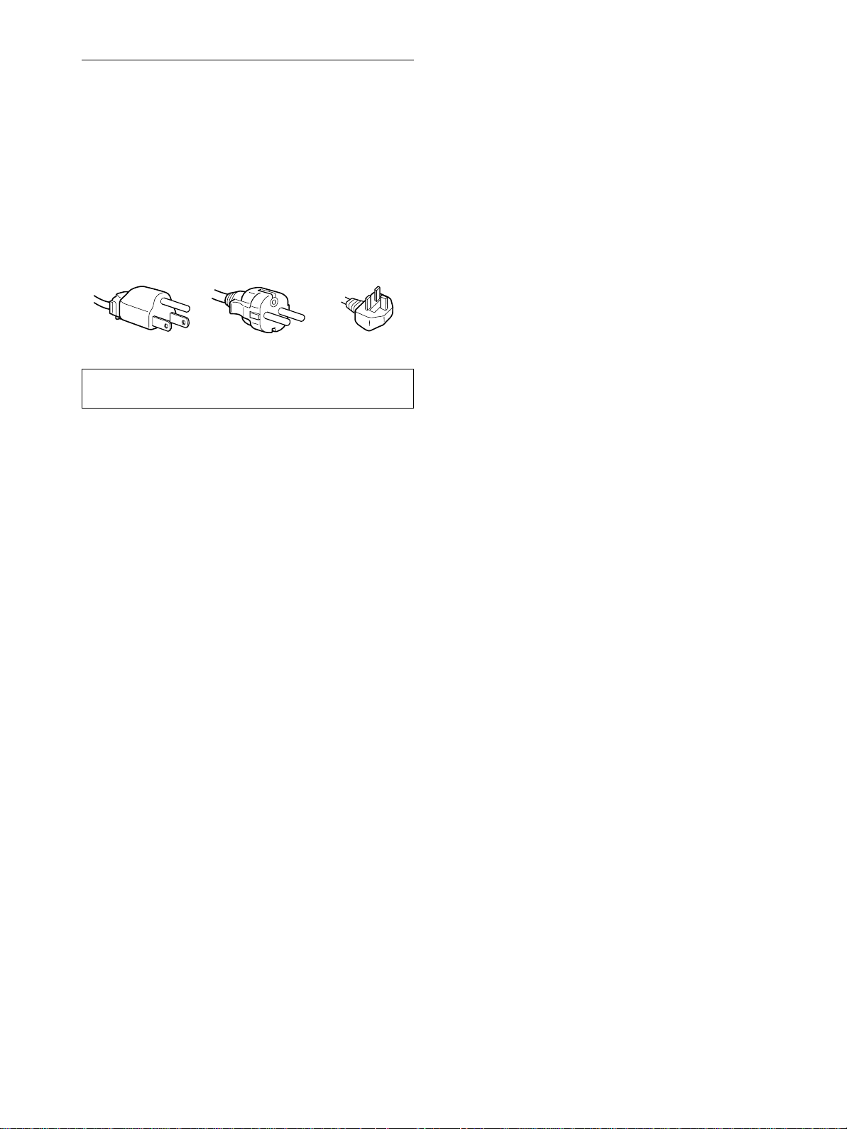
Example of plug types
for 100 to 120 V AC for 200 to 240 V AC for 240 V AC only
The equipment should be installed near an easily accessible
outlet.
Installation
Do not install or leave the monitor:
• In places subject to extreme temperatures, for example near a
radiator, heating vent, or in direct sunlight. Subjecting the
monitor to extreme temperatures, such as in an automobile
parked in direct sunlight or near a heating vent, could cause
deformations of the casing or malfunctions.
• In places subject to mechanical vibration or shock.
• Near any equipment that generates a strong magnetic field,
such as a TV or various other household appliances.
• Inplaces subject to inordinate amounts of dust, dirt, or sand, for
example near an open window or an outdoor exit. If setting u p
temporarily in an outdoor environment, be sure to take
adequate precautions against airborne dust and dirt. Otherwise
irreparable malfunctions could occur.
Handling the LCD screen
• Do not leave the LCD screen facing the sun as it can damage
theLCDscreen.Takecarewhenyouplacethemonitorbya
window.
• Donot push on or scratch the LCD screen. Do notplace a heavy
object on the LCD screen. This may cause the screen to lose
uniformity or cause LCD panel malfunctions.
• If the monitor is used in a cold place, a residual image may
appear on the screen. This is not a malfunction. The screen
returns to normal as the temperature rises to a normal operating
level.
• If a still picture is displayed for a long time, a residual image
may appear for a while. The residual image will eventually
disappear.
• The LCD panel becomes warm during operation. This is not a
malfunction.
Note on the LCD (Liquid Crystal Display)
Please note that the LCD screen is made with highprecision technology. However, black points or bright
points of light (red, blue, or green) may appear
constantly on the LCD screen, and irregular colored
stripes or brightness may appear on the LCD screen.
This is not malfunction. (Effective dots: more than
99.99%)
Maintenance
• Be sure to unplug the power cord from the power outlet before
cleaning your monitor.
• CleantheLCDscreenwithasoftcloth.Ifyouuseaglass
cleaning liquid, do not use any type of cleaner containing an
anti-static solution or similar additive as this may scratch the
LCD screen’s coating.
• Clean the cabinet, panel, and controls with a soft cloth lightly
moistened with a mild detergent solution. Do not use any type
of abrasive pad, scouring powder, or solvent, such as alcohol or
benzine.
• Do not rub, touch, or tap the surface of the screen with sharp or
abrasive items such as a ballpoint pen or screwdriver. This type
of contact may result in a scratched picture tube.
• Note that material deterioration or LCD screen coating
degradation may occur if the monitor is exposed to volatile
solvents such as insecticide, or if prolonged contact is
maintained with rubber or vinyl materials.
Transportation
• Disconnect all cables from the monitor when transporting.
When you transport this display, grasp the support and base
sections of the display stand firmly with both hands. Also use
both hands when carrying the media engine. If you drop the
monitor, you may be injured or the monitor may be damaged.
• Whenyou transport this monitor for repair or shipment, use the
original carton and packing materials.
Replacement of the fluorescent tube
A specially designed fluorescent tube is installed as the lighting
apparatus for this monitor. If the screen becomes dark, unstable,
or does not turn on, replace the fluorescent tube with a new one.
Consult your Sony dealer when replacing the fluorescent tube.
Disposal of the monitor
• Do not dispose of this monitor with general
household waste.
• The fluorescent tube used in this monitor contains
mercury.Disposalof this monitor mustbe carried out
in accordance to the regulations of your local
sanitation authority.
4
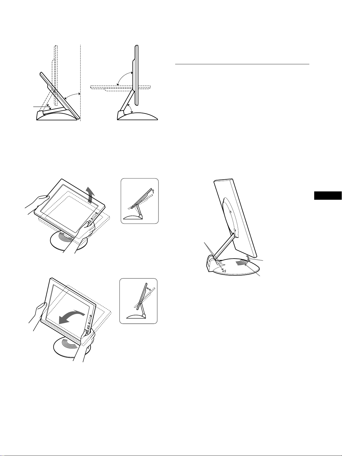
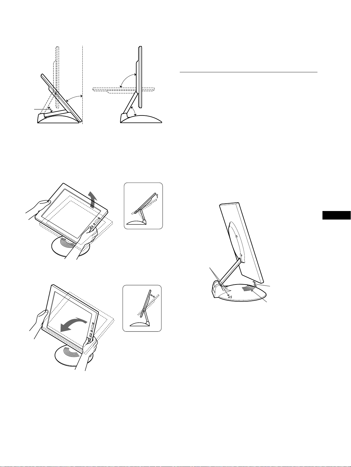
To adjust the tilt and height
This display can be adjusted within the angles shown below.
To use the display comfortably
This display is designed so that you can set it up at a comfortable
viewing angle. Adjust the viewing angle of your display
accordingtotheheightofthedeskandchair,andsothatlightis
not reflected from the screen to your eyes.
90°
40°
50°
To adjust the angles, grasp the lower sides of the LCD panel with
both hands as shown below. Tilt the LCD panel adequately
backward,then lift the LCD panel upward to the desired screen
height, then adjust the screen tilt as desired. When adjusting the
screenheightand tilt, proceed slowly andcarefully,beingsure not
to hit the LCD panel against the desk or the base of the display
stand.
50°
To enjoy clear sound from the builtin stereo speaker
This monitor has a built-in stereo speaker in base of the display
stand.
We recommend that you position the LCD panel slightly away
from the display stand. High tones from the speaker may be
muffled if the LCD panel is positioned immediately on top of the
stand. Be careful not to drop any metal object into the speaker's
vents as the speakers generate a magnetic field. Also, this
magnetic field may affect data stored on magnetic tapes and discs.
Be sure to keep magnetic recording equipment, tapes, and floppy
discs away from the speaker’s opening.
A duct is provided on the rear part of the display stand to boost the
bass. Be sure not to block the duct with paper or other objects to
ensure clear sound.
GB
m
Ducts
Keept he LCD panel
slightly away from
the base.
Speaker
5

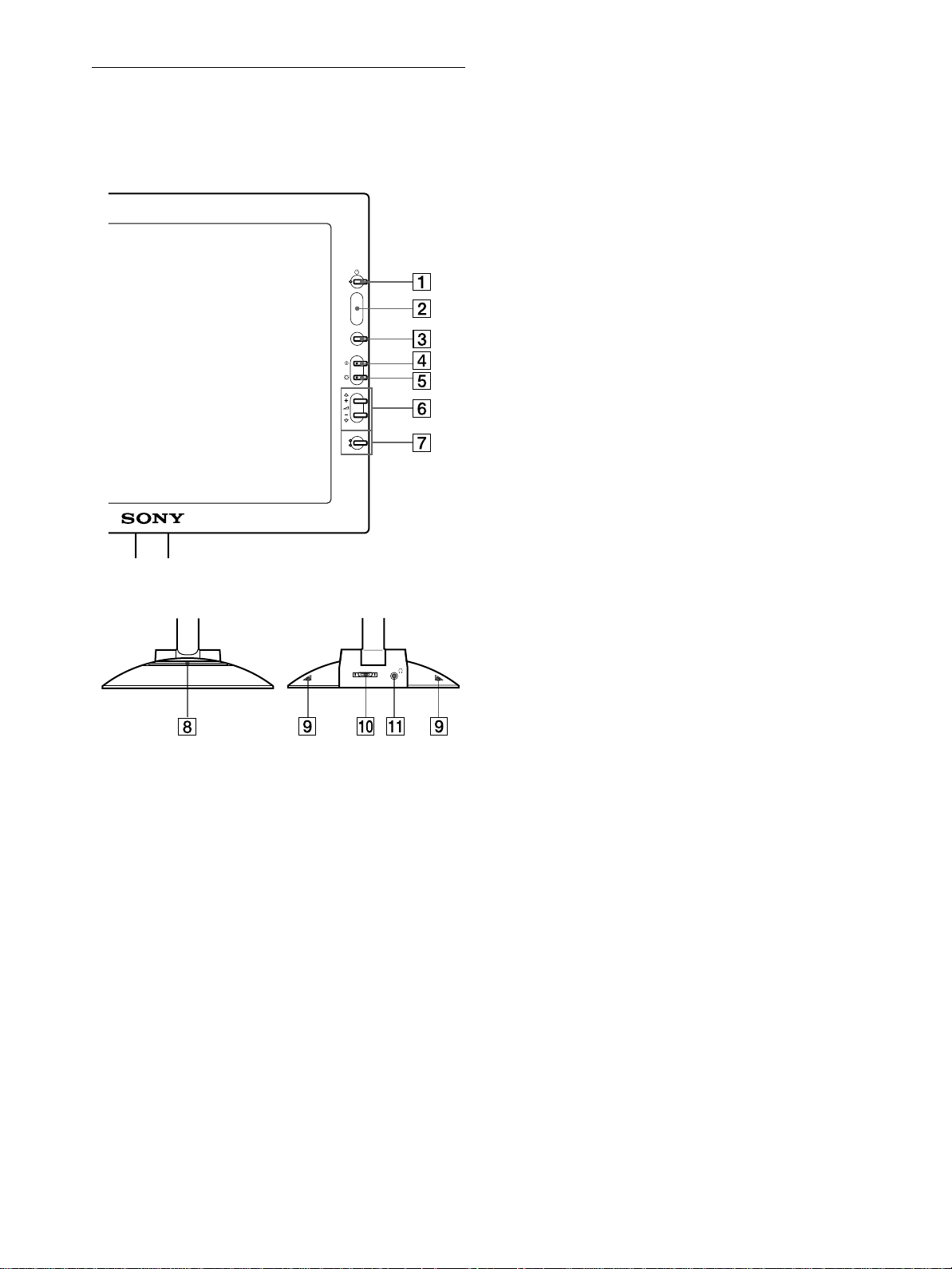
Identifying parts and controls
See the pages in parentheses for further details.
LCD display
MENU
INPUT
1
2
OK
6 2 (volume) +/– and M(+)/m(–) buttons
(pages 10, 12)
These buttons display the VOLUME menu and function as
the M(+)/m(–) buttons when selecting the menu items and
making adjustments.
7 INPUT and OK button, and indicator (pages 10, 12)
This button selects the INPUT 1 or INPUT 2 (HD15 (RGB)
connectors) video input signal. The input signal and
corresponding input indicator change each time you press this
button.
This button also functions as the OK button when displaying
themenuonthescreen.
8 Stereo speaker (page 10)
This outputs the audio signals as sound.
9 Ducts
These are used to boost the bass sound from the speaker.
0 SYSTEM CONNECTOR (page 8)
Thisconnectorinputs signalsfromthe mediaenginewhen the
display and the media engine are connected with a system
connecting cable.
qa Headphones jack (page 10)
This jack outputs audio signals to the headphones.
Front
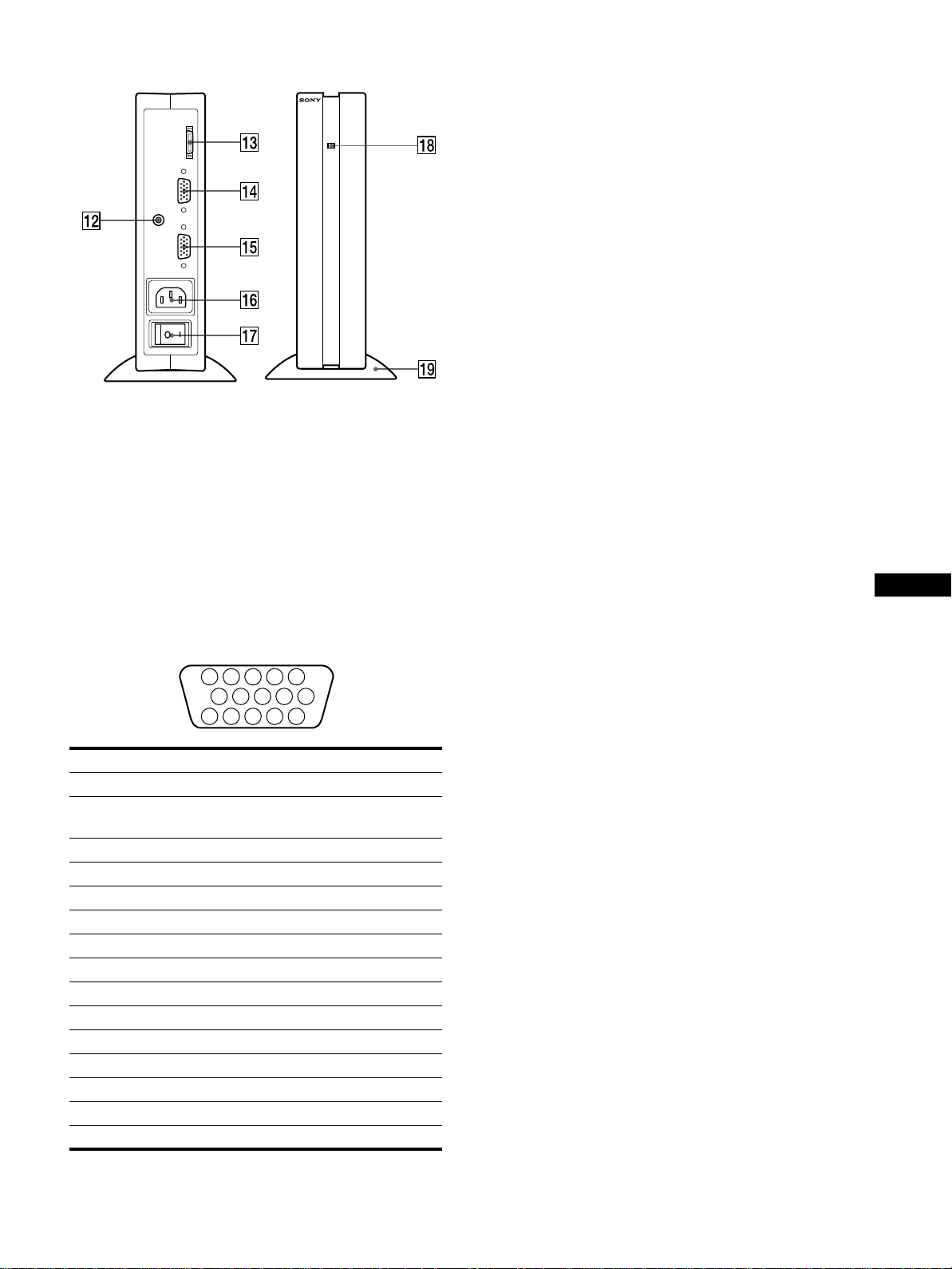
Rear
SYSTEM CONNECTER
1 1 (Power) switch and indicator (pages 9, 17, 22)
This switch turns the display on and off.
Theindicatorlights up in green whenthemonitoris turned on.
The indicatorflashesin green and orange when the monitor is
in low power consumption mode, and lights up in orange
when the monitor is in power saving mode.
2 Light sensor and user sensor (pages 16, 17, 18)
These sensors measure the brightness of the surrounding area
and detect when a user becomes present in front of the screen.
Be sure not to cover the sensor with papers, etc.
3 MENU button (page 12)
This button displays the main menu.
4 6 (contrast) button (page 12)
This button displays the CONTRAST menu.
5 8 (brightness) button (page 12)
This button displays the BRIGHTNESS menu.
6

Media engine
SYSTEM CONNECTER
AUDIO IN
(
TO DISPLAY
INPUT 1
INPUT 2
qg HD15 (RGB) input 2 connector (INPUT2) (page 8)
This connector inputs RGB video signals (0.700 Vp-p,
positive) and SYNC signals. The pin assignment is the same
as qf.
)
qh AC IN connector (page 9)
This connector provides AC power to the monitor.
qj AC power switch (page 9)
Thisswitch turns the monitor on and off. When the AC power
switch is turned on, the display automatically turns on.
qk AC power indicator (page 17)
This indicator lights up in green when the media engine is
turned on. The indicator lights up in red when the display is
turnedoffwith the media engine on. The indicator lights up in
orange when the monitor is in the power saving mode.
ql Media engine stand
This stand is used to install the media engine vertically.
qs AUDIO IN jack (page 10)
This jack inputs audio signals when connecting to the audio
output jack of the computer or other audio equipment.
qd SYSTEM CONNECTOR (TO DISPLAY) (page 8)
Thisconnectoroutputssignalstothe display when the display
and the media engine are connected with a system connecting
cable.
qf HD15 (RGB) input 1 connector (INPUT1) (page 8)
This connector inputs RGB video signals (0.700 Vp-p,
positive) and SYNC signals.
5 4 3 2
1
678910
1112131415
Pin No. Signal
1Red
2 Green
(Sync on Green)
3Blue
4 ID (Ground)
5 DDC Ground*
6 Red Ground
7 Green Ground
8BlueGround
9 DDC + 5V*
10 Ground
11 ID (Ground)
12 Bi-Directional Data (SDA)*
13 H.Sync
14 V. Sync
15 Data Clock (SCL)*
Caution
Be sure to install the media engine vertically shown as left. Installing the
media engine lying flat may block ventilation, and may cause a
malfunction.
GB
* DDC (Display D ata Channel) is a standard of VESA.
7
Setup
Before using your monitor, check that the following items are
included in your carton:
• LCD display
• Media engine
• Mediaenginestand
• Power cord
• System connecting cable (2 m)
(applicable cable type: DP-2)
• HD15 (RGB) video signal cable
• Audio cord (stereo miniplug)
• Windows Monitor Information Disk/Utility Disk
• Macintosh Utility Disk
• Warranty card
• This instruction manual
Step 1:Connect the media eng ine
to your computer
Turn off the media engine and computer before connecting.
Note
Do not touch the pins of the video signal cable connector as this might
bend the pins.
Connecting to a Macintosh
x
to INPUT1 or
INPUT2 connector
to video output
Macintosh
When connecting this monitor to a Macintosh computer, use the
Macintosh adapter if necessary. Connect the Macintosh adapter to the
computer before connecting the cable.
HD15 (RGB) video
signal cable (supplied)
Connecting to an IBM PC/AT or compatible
x
computer
to INPUT1 or
INPUT2 connector
to video output
HD15 (RGB) video
IBM PC/AT or
IBM PC/AT or
compatible computer
compatible computer
signal cable (supplied)
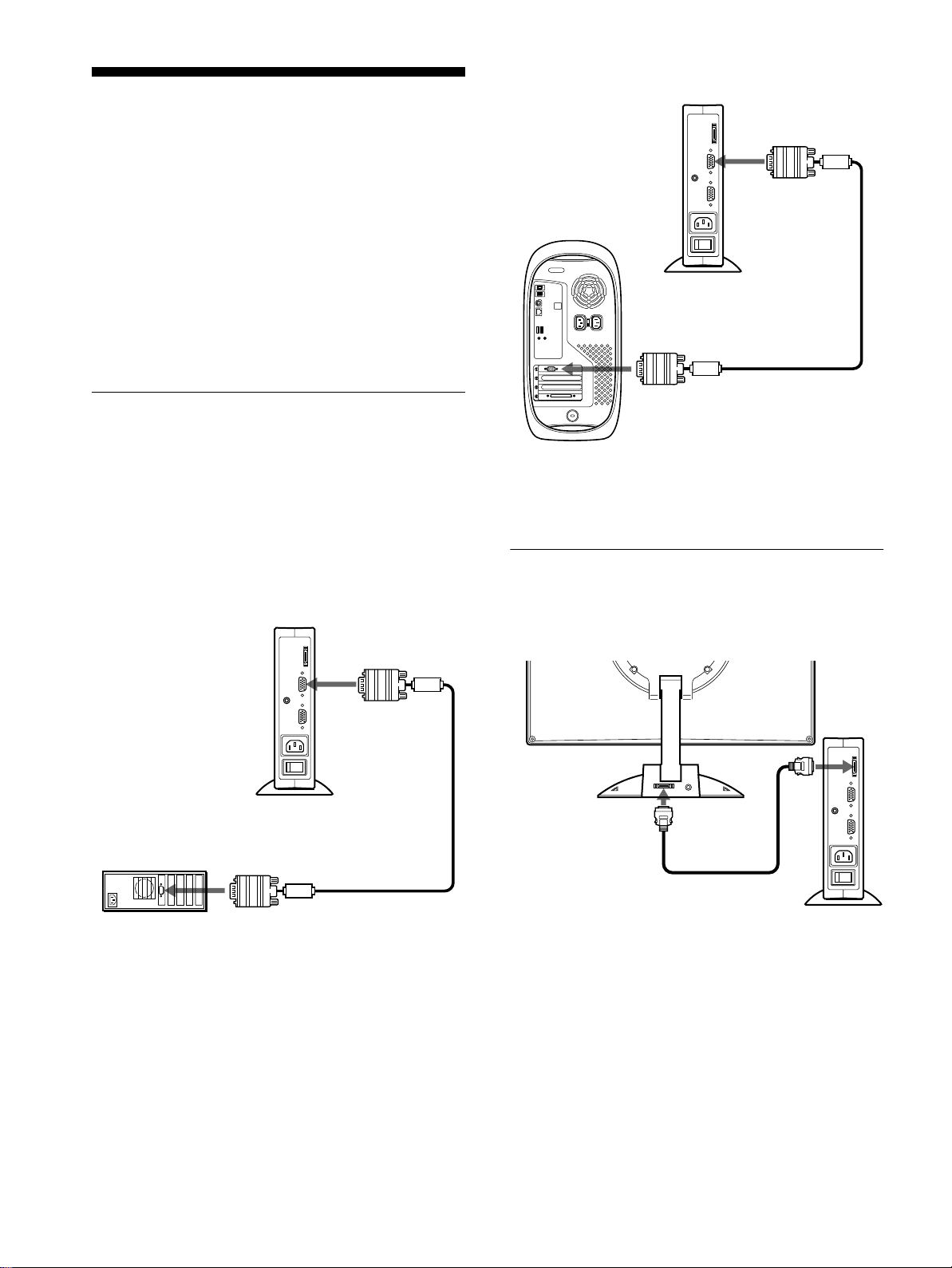
Step 2:Connect the display and
media engine
Turn off the display and media engine before connecting.
to SYSTEM
CONNECTOR
of the display
Caution
Be sure to install the media engine vertically as shown above. Installing
the media engine lying flat may block ventilation, and may cause a
malfunction.
to SYSTEM
CONNECTOR
of the media
engine
system connecting
cable (2 m) (supplied)
Note
Grasp the plug when connecting the cable.
8
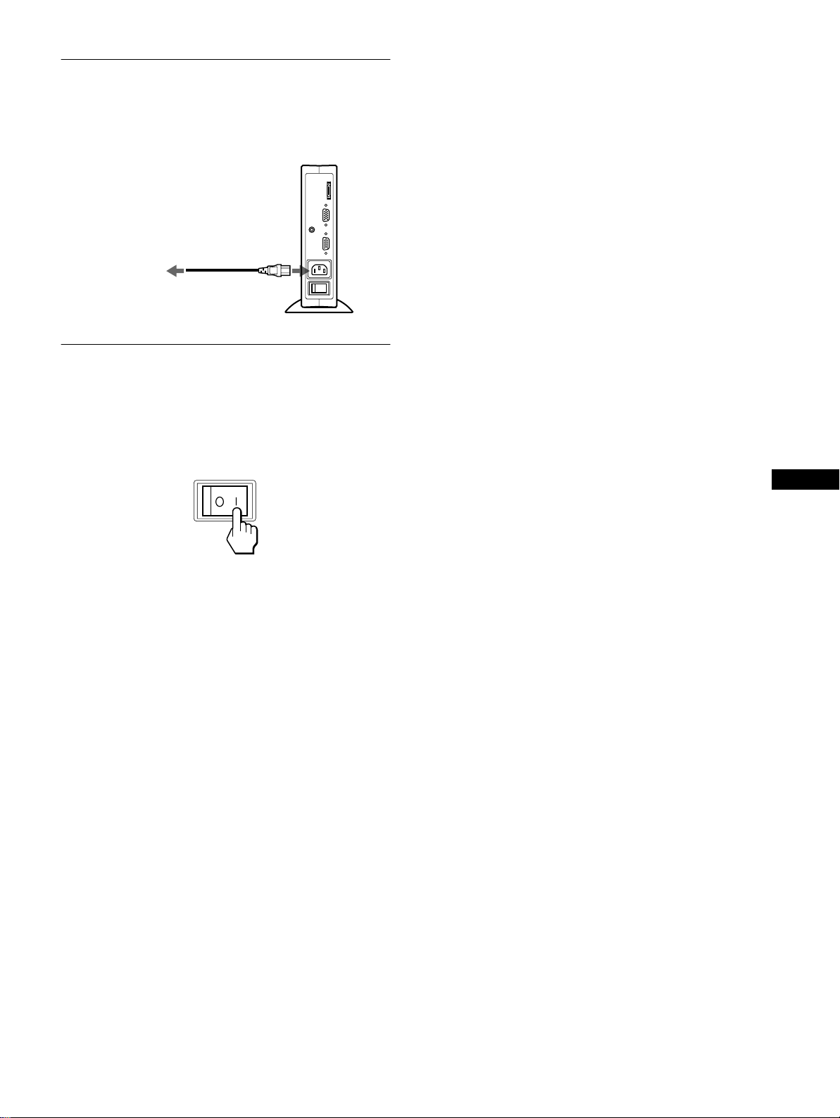
Step 3:Connect the power cord
With the media engine, display, and computer switched o ff,
first connect the power cord to the media engine, then connect it
to a power outlet.
to AC IN
to a power outlet
power cord (supplied)
Step 4:Turn on the monitor and
computer
Turn on the media engine.
1
The d isplay automatically turns on. The indicators of the
media engine and display light up in green.
If no picture appears on your screen
• Check that the monitor is correctly connected to the computer.
• Check that the media engine is on.
• If NO INPUT SIGNAL appears on the screen, the computer is
in the power saving mode. Try pressing any key on the
keyboard or moving the mouse.
• If CABLE DISCONNECTED appears on the screen, try
changing the input signal (page 10), and check that the video
input cable is properly connected.
• If OUT OF SCAN RANGE appears on the screen, reconnect
the old monitor. Then adjust the computer’sgraphicboardso
that the h orizontal frequency is between 30 – 61 kHz, and the
vertical frequency is between 48 – 85 Hz (only XGA mode at
75 Hz).
Formoreinformationabouttheon-screenmessages,see“Trouble
symptoms and remedies” on page 20.
No need for specific drivers
The monitor complies w ith the “DDC ” Plug & Play standard and
automaticallydetects all the monitor’s information. No specificdriver
needs to be installed to the computer.
The first time you turn on your computer after connecting the monitor, the
setup Wizard may appear on the screen. In this case, follow the on-screen
instructions. The Plug & Play monitor is automatically selected so that
you ca n use this monitor.
The vertical frequency turns to 60 Hz.
Since flickers are unobtrusive on the monitor, you can use it as it is. You
do not need to set the vertical frequency to any particular high value.
GB
Turn on the computer.
2
The installation of your monitor is complete. If necessary, use the
monitor’s controls to adjust the picture.
If your computer or graphicsboard has difficulty communicating with this
monitor, install the information file for this monitor using the Windows
Monitor Information Disk. For details on installing, refer to the ReadMe
file on the disk.
9
Using the stereo speaker
Selecting the input signal
You can listen to music, sounds, and other audio files using the
stereospeakerofyourmonitor.
Connect the AUDIO IN jack to the audio output jack of your
computer or other audio equipment using the supplied audio cord
(stereo miniplug).
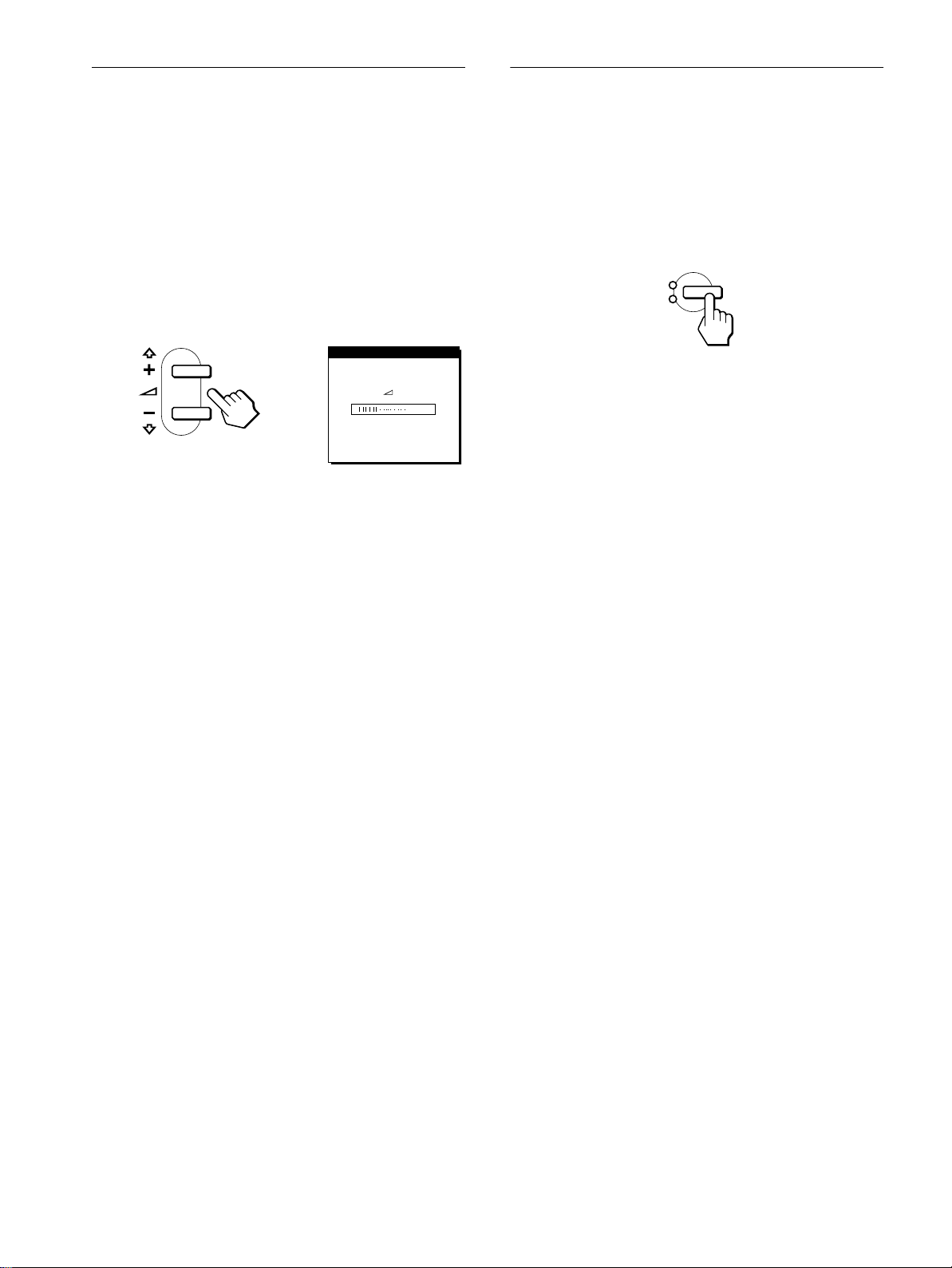
Adjusting the volume
Volume adjustments are made using a separate VOLUME menu
from the main menu (page 11).
1
Press the 2 +/– buttons.
The VOLUME menu appears on the screen.
VOL UME
40
2
Press the 2 +/– button to adjust the volume.
The menu automatically disappears after about 3 seconds.
Using the headphones jack
You can listen to the audio signals from your computer or other
audio equipment using headphones. Connect your headphones to
the headphones jack. The speaker turns off when headphones are
connected to the headphones jack. Adjust the volume of the
headphones using the VOLUME menu.
You can connect two computers to this monitor using the INPUT
1 and INPUT 2 connectors. To select one of the two computers,
use the INPUT button.
Press the INPUT button.
The input signal and corresponding input indicator, “1” (INPUT
1) or “2” (INPUT 2) change each time you press this button.
INPUT
1
2
OK
Notes
• You cannot select the input signal when displaying the main menu on
the screen.
• If no signal is input t o the selected connector, NO INPUT SIGNAL or
CABLE DISCONNECTEDa ppears on the screen.Aftera few seconds,
the monitor enters the power saving mode. If this happens, select the
other connector using the INPUT button.
Notes
• You cannot adjust the volume when displaying the main menu on the
screen.
• When your monitor is in low power consumption mode or power
saving mode, no sound comes from the speaker.
10

Customizing Your Monitor
Before making adjustments
Connect the monitor and the computer, and turn them on.
Wait for at least 30 minutes before making adjustments for the
best result.
4 V CENTER (page 13)
Select the V CENTER menu
toadjustthe picture’svertical
centering.
VCENTER
25
EX I T
You can make numerous adjustments to your monitor using the
on-screen menu.
Navigating the menu
Pressthe MENU button to display the main menu on your screen.
Seepage12formoreinformationonusingtheMENUbutton.
MENU
Use the M(+)/m(–) and OK buttons to select one of the following
menus.Seepage12formoreinformationonusingthe
M(+)/m(–) and OK buttons.
1 PHASE (page 13)
Select the PHASE menu to
adjust the phase when the
characters or pictures appear
fuzzy throughout the entire
screen. Adjust the phaseafter
adjusting the pitch.
PHASE
PHASE
16
EX I T
5 ZOOM (page 14)
Select the ZOOM menu to
adjustthepicture’s sharpness
accordingtotheinput
signal’s aspect ratio or
resolution.
6 COLOR (page 14)
Select the COLOR menu to
adjust the color temperature
of the picture. This adjusts
thetoneofthescreen.
7 MENU POSITION
(page 14)
Select the MENU
POSITION to change the onscreen menu position.
8 RESET (page 15)
Select the RESET menu to
reset the adjustments.
ZOOM
ON
OFF
COLOR
9300K
650
5000K
USER
ALDJUST
MEN NUP
RESET
S CREEN
ALL
0K
OS I I OT
RESET
EX I T
EX I T
GB
EX I T
RESET
2 PITCH (page 13)
Select the PITCH menu to
adjust the pitch when the
characters or pictures are
unclear in some areas of the
screen.
3 H CENTER (page 13)
Select the H CENTER menu
to adjust the picture’s
horizontal centering.
PITCH
HCENTER
EX I T
50
EX I T
EX I T
9 Option (page 15)
0
Select m (option) menu to
adjust the monitor’s options.
The options include:
WI DE S TEREO
1
2
O
FF
• WIDE STEREO
• BASS BOOST
• BACKLIGHT
• LIGHT SENSOR
EX I T
• POWER SAVE
• USER SENSOR
• LANGUAGE
• MENU LOCK
(continued)
11
Using the MENU,M(+)/m(–), and OK buttons
x
1
Display the main menu.
Press the MENU button to display the main menu on your
screen.
Adjusting the contrast (CONTRAST)
Contrast adjustment is made using a separate CONTRAST menu
from the main menu (page 11). This setting is stored in memory
for the signal from the currently selected input connector.
MENU
2
Select the menu you want to adjust.
Press the M(+)/m(–) buttons to display the desired menu.
Press the OK button to select the menu item.
INPUT
1
2
OK
3
Adjust the menu.
,
Press the M(+)/m(–) buttons to make the adjustment. Then
press the OK button to return to the previous menu.
INPUT
1
2
OK
4
Close the menu.
,
Press the MENU button once to return to normal viewing. If
no buttons are pressed, the menu closes automatically after
about 30 seconds.
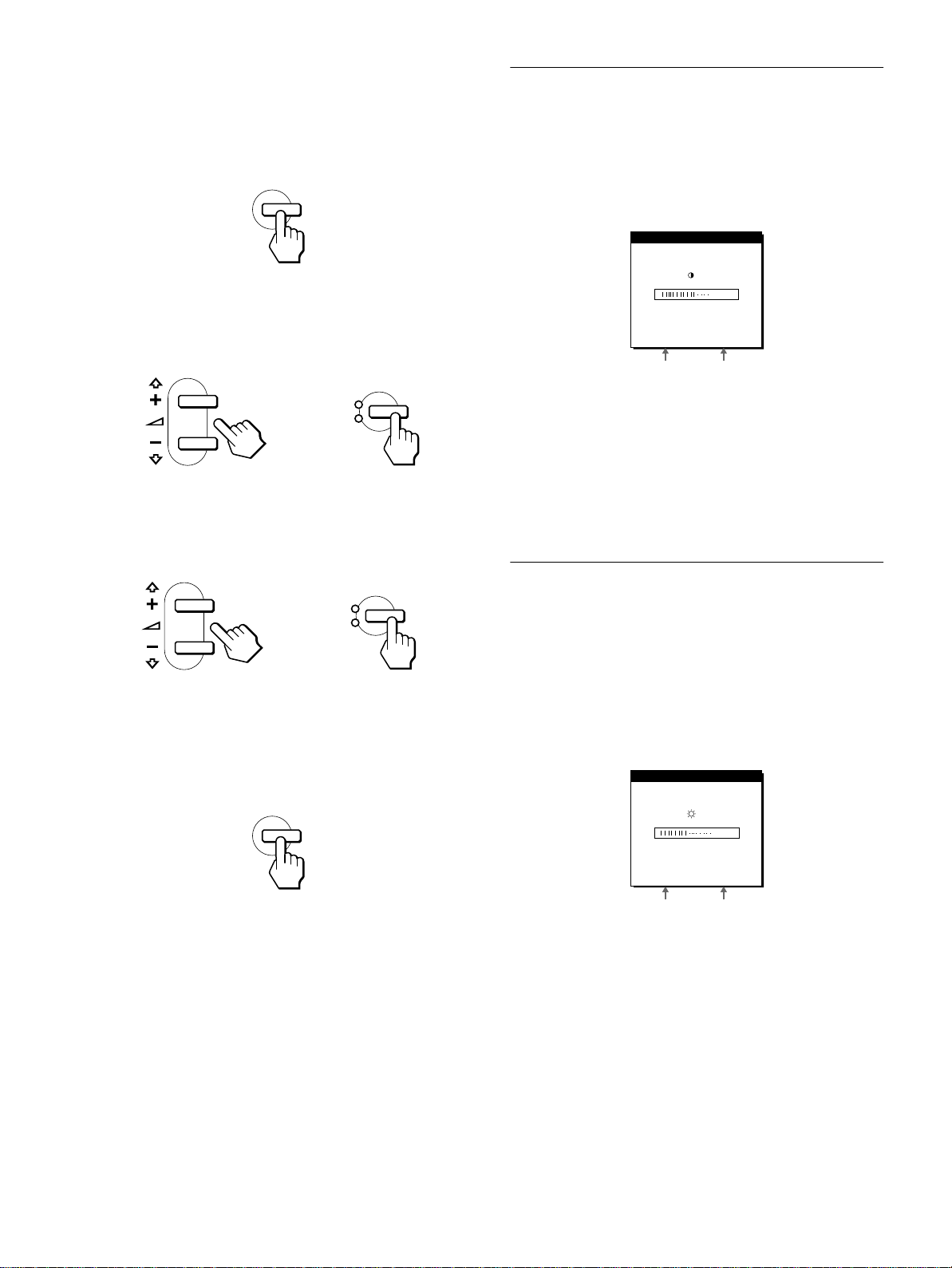
1
Press the 6 (contrast) button.
The CONTRAST menu appears on the screen.
CONTRAST
70
48.4kHz/ 60Hz
Horizontal frequency
of the current input
signal
Displaying the current input signal
The horizontal and vertical frequencies of the current input signal are
displayed in the CONTRAST and BRIGHTNESS menu.
2
Press the M(+)/m(–) buttons to adjust the contrast.
Vertical frequency of
the current input
signal
The menu automatically disappears after about 3 seconds.
Adjusting the black level of an
image (BRIGHTNESS)
Brightness adjustment is made using a separate BRIGHTNESS
menu from the main menu (page 11). This setting is stored in
memory for the signal from the currently selected input
connector.
1
Press the 8 (brightness) button.
The BRIGHTNESS menu appears on the screen.
B NESSRIGHT
MENU
Resetting the adjustments
x
You can reset the adjustments using the RESET menu. See
page 15 for more information on resetting the adjustments.
12
50
48.4kHz/ 60Hz
Horizontal frequency
of the current input
signal
2
Press the M(+)/m(–) buttons to adjust the
Vertical frequency of
the current input
signal
brightness.
The menu automatically disappears after about 3 seconds.
If the screen is too bright
Adjust the backlight. For more information about adjusting the
backlight, see “Adjusting the backlight” on page 16.
Note
You can adjust neither contrast nor brightness when displaying the main
menu on the screen.
Eliminating flicker or blurring
(PHASE/PITCH)
When the monitor receives an input signal, the automatic picture
quality adjustment function of this monitor automatically adjusts
the p icture position, phase, and pitch, and ensures that a clear
picture appears on the screen. For more information about this
function,see “Automatic picture quality adjustment function” on
page 18.
For some input signals, this function may not completely adjust
the picture position, phase, and pitch. In this case, you can
manually set these adjustments according the following
instructions. If you manually set these adjustments, they are
stored in memory and automatically recalled whenever the
monitor receives the same input signals.
Thesesettingsmayhavetoberepeatedifyouchangetheinput
signal after reconnecting your computer.
Set the resolution to 1024 ×××× 768 on the computer.
1
Load the Utility Disk.
2
Use the appropriate disk for your computer.
For Windows
Windows Monitor Information Disk/Utility Disk
For Macintosh
Macintosh Utility Disk
Start the Utility Disk and display the test pattern.
3
For Windows
[Windows]/[Utility.exe].
Click [Utility Disk]
For Macintosh
Click [Utility Disk]
t
[SONY-Utility].
t
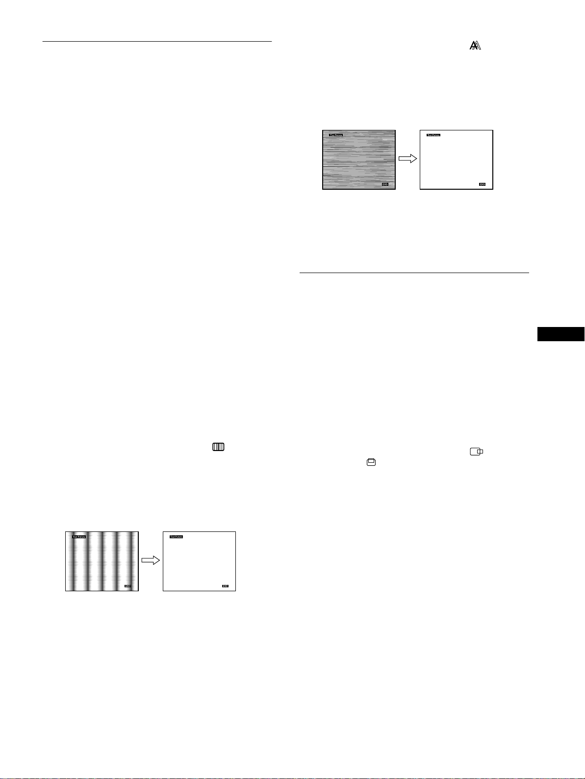
Press the M(+)/m(–) buttons to select (PHASE)
8
and press the OK button.
The PHASE menu appears on the screen.
Press the M(+)/m(–) buttons until the screen color
9
becomes uniform.
Adjust so that the horizontal stripes are at a minimum.
Click [END] on the screen to turn off the test pattern.
10
To reset the automatic picture qua lity adjustment
Select SCREEN RE SET and activate it using the RESET menu. See
page 15 for more information on using the RESET menu.
Adjusting the picture position
(H CENTER/V CENTER)
If the picture is not in the center of the screen, adjust the picture’s
centering as follows.
These settings may have to be repeated if you change the input
signal after reconnecting your computer.
Start the Utility Disk and display the test pattern.
1
Repeat steps 2 and 3 of “Eliminating flicker or blurring
(PHASE/PITCH).”
GB
Press the MENU button.
4
The main menu appears on the screen.
Press the M(+)/m(–) buttons to select (PITCH)
5
and press the OK button.
The PITCH menu appears on the screen.
Press the M(+)/m(–) buttons until the screen color
6
becomes uniform.
Adjust so that the vertical stripes disappear.
Press the OK button.
7
The main menu appears on the screen.
If horizontal stripes are observed over the entire screen, adjust
the phase as the next step.
Press the MENU button.
2
The main menu appears on the screen.
Press the M(+)/m(–) buttons to select (H
3
CENTER) or (V CENTER) and press the OK
button.
The H CENTER or V CENTER menu appears on the screen.
Move the picture up, down, left, or right until the
4
frame at the perimeter of the test pattern
disappears.
Press the M(+)/m(–) buttons to adjust the picture’s
centering using the H CENTER menu for horizontal
adjustment, or the V CENTER menu for vertical
adjustment.
Click [END] on the screen to turn off the test pattern.
5
13
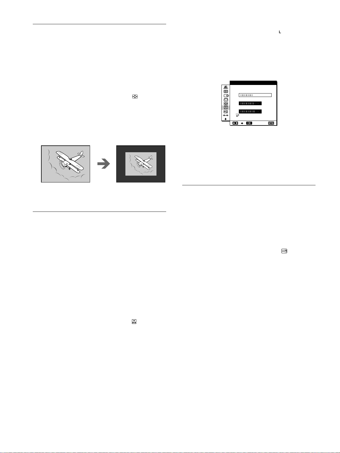
Displaying a low-resolution signal
at the actual resolution (ZOOM)
This monitor is preset at the factory to display pictures on the
screen in full, irrespective of the picture’s mode or resolution.
You can also view the picture at its actual resolution.
1
Press the MENU button.
The main menu appears on the screen.
4
If necessary, fine tune the color temperature.
First press the M(+)/m(–) buttons to select ADJUST and
press the OK button. Then press the M(+)/m(–) buttons to
select R (Red) or B (Blue) and press the OK button, and then
press the M(+)/m(–) buttons to adjust the color temperature.
Since this adjustment changes the color temperature by
increasing or decreasing the R and B components with respect
to G (green), the G component is fixed.
USER AD J UST TMEN
2
Press the M(+)/m(–) buttons to select (ZOOM)
and press the OK button.
The ZOOM menu appears on the screen.
3
Press the m(–)buttontoselectOFF.
The input signal is displayed on the screen at its actual
resolution.
To display the picture on the screen in full
Select ON in step 3.
Adjusting the color temperature
(COLOR)
The COLOR settings allow you to adjust the picture’s color
temperature by changing the color le vel of the white color field.
Colors appear reddish if the temperature is low, and bluish if the
temperature is high.
9300K is generally suitable for word processing and other text
oriented applications, and 6500K is generally suitable for video
images.
You can set the color temperature to 5000K, 6500K, 9300K or
user adjustment.
1
Press the MENU button.
The main menu appears on the screen.
R168
G170
B175
EX I T
If you fine tune the color temperature, the new color setting is
stored in memory for USER ADJUSTMENT and
automatically recalled whenever USER is selected.
The USER ADJUSTMENT setting is common to both the
input signals. If you change the user adjustment setting for
one input signal, the setting for the other input signal is also
changed.
Changing the menu’s position
(MENU POSITION)
You can change the menu position if it is blocking an image on
the screen.
1
Press the MENU button.
The main menu appears on the screen.
2
Press the M(+)/m(–) buttons to select (MENU
POSITION) and press the OK button.
The MENU POSITION menu appears on the screen.
3
Press the M(+)/m(–) buttons to select the desired
position.
There are three positions each for the top of the screen and the
bottom of the screen, and one for the screen center.
2
Press the M(+)/m(–) buttons to select (COLOR)
and press the OK button.
The COLOR menu appears on the screen.
3
Press the M(+)/m(–) buttons to select the desired
color temperature.
Thepresetcolortemperaturesare 5000K,6500K,and 9300K.
Since the default setting is 9300K, the whites will change
from a bluish hue to a reddish hue as the temperature is
loweredto6500Kand5000K.
You can set separate color temperatures for each of the video
input signals.
14

Resetting the adjustments (RESET)
Additional settings (Option)
This monitor has the following two reset methods. Use the
RESET menu to reset the adjustments.
Press the MENU button.
1
The main menu appears on the screen.
Press the M(+)/m(–) buttons to select 0000 (RESET)
2
and press the OK button.
The RESET menu appears on the screen.
Reset the settings according to the following instructions.
Resetting the adjustment data most appropriately
for the current input signal
Press the M(+)/m(–) buttons to select SCREEN RESET
and press the OK button.
The automatic picture quality adjustment functionof this monitor
automaticallyadjuststhe picture position, phase, and pitch, to the
most a ppropriate value. If this function is activated, the phase is
automatically adjusted whenever the monitor receives the same
input signal.
The RESET menu is automatically returned to the main menu
after the adjustment data is reset.
Resetting all of the adjustment data for all input
signals
Press the M(+)/m(–) buttons to select ALL RESET and
press the OK button.
The RESET menu is automatically returned to the main menu
after the adjustment data is reset.
To cancel resetting
Press the M(+)/m(–) buttons to select andpress the
OK button.
The RESET menu returns to the main menu without resetting the
adjustment data.
You can adjust the following options:
• WIDE STEREO
• BASS BOOST
• BACKLIGHT
• LIGHT SENSOR
• POWER SAVE
• USER SENSOR
• LANGUAGE
• MENU LOCK
Press the MENU button.
1
The main menu appears on the screen.
Press the M(+)/m(–) buttons to select m.
2
The option menu appears on the screen.
Press the M(+)/m(–) buttons to select the desired
3
option item and press the OK button.
Adjust the selected option item according to the following
instructions.
Increasing the soundscape (wide stere o function)
This adjustment makes use of the DSP and creates the illusion of
the built-in stereo speaker being further away than it actually is,
thus enhancing sound presence.
First press the M(+)/m(–) buttons to select (WIDE
STEREO) and press the OK button. Then press the
M(+)/m(–) buttons to select either 2, 1, or OFF.
The wide stereo function is used to increase the soundscape.
Selecting 1 or 2 increases incrementally the soundscape effect
toward the front of the monitor.
Notes
• If your connected computer or audio equipment uses special sound
functions, such as surround sound, be sure to turn these functions off.
If these functions are being used with the wide stereo function of this
monitor, the wide stereo function may not function properly and thus
not produce the desired sound effect.
• This function is automatically turned off when you use headphones.
However,in thiscase, the indication in the WIDE STEREO menu does
not change.
• The wide stereo function allows you to increase the soundscape by
converting the analog signals into digital. The sound may be distorted
depending on the input signal and music. In this case, decrease the
volume or set the wide stereo function to OFF.
GB
Boosting the bass (bass boost function)
This option increases the bass output of the speaker.
First press the M(+)/m(–) buttons to select (BASS
BOOST) and press the OK button. Then press the
M(+)/m(–) buttons to select either ON or OFF.
(continued)
15

Adjusting the backlight
If the screen is too bright, adjust the backlight.
First press the M(+)/m(–) buttons to select
(BACKLIGHT) and press the OK button. Then press
the M(+)/m(–) buttons to adjust the desired light level.
Automatically adjusting the screen brightness
(light sensor)
This monitor is provided with a sensor to detect the brightness of
the surrounding area (light sensor). This sensor is used to
automatically adjust the brightness of the screen.
First press the M(+)/m(–) buttons to select (LIGHT
SENSOR) and press the OK button. Then press the
M(+)/m(–) buttons to select either ON or OFF.
WhenyouselectON,themonitorautomaticallya djusts the screen
brightness according to the brightness of the surroundings. For
more information about this function, see “Automatic brightness
adjustment function (light sensor)” on page 18.
Note
If this function is set to ON, the value of the BACKLIGHT menu does not
change. If the screen brightness is still not appropriate after the automatic
adjustment, you can manually adjust the backlight. After the backlight
adjustment is made, the monitor automatically adjusts the screen
brightnessin accordance with the new backlight value.
Setting up the power saving mode
This monitor has a function which enables it to enter the power
save mode automatically according to the power saving settings
of the computer. You can prevent the monitor from entering the
power saving mode by setting the following option to OFF.
First press the M(+)/m(–) buttons to select (POWER
SAVE) and press the OK button. Then press the
M(+)/m(–) buttons to select either ON or OFF.
ZZ...
Selecting the on-screen menu language
English, German, French, Spanish, Italian and Japanese versions
of the on-screen menus are available. The default setting is
English.
First press the M(+)/m(–) buttons to select
(LANGUAGE) and press the OK button. Then press
the M(+)/m(–) button to select a language.
• ENGLISH
• DEUTSCH: German
• FRANÇAIS: French
• ESPAÑOL:Spanish
• ITALIANO: Italian
• : Japanese
Locking the menus and controls
You can protect adjustment data by locking the menus and
controls.
First press the M(+)/m(–) buttons to select (MENU
LOCK) and press the OK button. Then press the
M(+)/m(–) buttons and select ON.
Only the 1 (power) switch, and (MENU LOCK) of the
optionmenuwilloperate.If any other items are selected, the
mark appears on the screen.
To cancel the menu lock
Repeat the procedure above and set (MENU LOCK) to OFF.
Using the user sensor
The user sensor function enables the monitor to enter the low
power consumption mode when no one is present in front of the
monitor.
First press the M(+)/m(–) buttons to select (USER
SENSOR) and press the OK button. Then press the
M(+)/m(–) buttons to select either ON or OFF.
If you select ON, the monitor automatically enters the low power
consumptionmode when you move away from the front of the
monitor. For more information about the low power consumption
mode, see “Power saving function (user sensor/power saving
mode)” on page 17.
16

Technical Features
Power saving function (user sensor/power saving mode)
This monitor meets the power-saving guidelines set by VESA,ENERGYSTAR, and NUTEK. If the monitor is connected to a computer
or video graphics board that is DPMS (Display Power Management Signaling) compliant, the monitor will automatically enter the power
saving mode. It automatically enters the low power consumption mode when the user sensor detects the absence of a user.
Power consumption state Power consumption AC power indicator 1 (power) indicator
normal operation 35 W green green
1 low power consumption mode ≤ 8 W green green and orange alternate
2 power saving mode ≤ 3 W orange orange
1 (power): off ≤ 3 Wred off
AC power: off 0 W off off
1 Low power consumption mode (user sensor)
Whenthe user sensor in the monitordetectsthe absenceof a user,
the m onitor enters low power consumption mode after about 20
seconds. In low power consumption mode, the monitor is in a
power saving state and shuts off power to all circuitry (except for
that of the sensors) regardless of the setting of the computer.
The monitor returns to normal operation mode when the presence
of a user is detected by the user sensor.
Whenthe monitor enters the power saving mode (as set according
to the computer’s settings), the power saving mode takes
precedence over the low power consumption mode. In this case,
the monitor stays in the power saving mode regardless of the
presence or absence of a user.
To return the monitor to normal operation mode, reset the
computer’s power saving mode.
Note
The user sensor detects the presence/absence of a user up to a distance of
approximately 60 cm from the screen surface. However, this distance may
vary depending on the user’s clothes or the brightness of the surrounding
area. If user detection fails due to the ambient conditions of the
surrounding area, set the user sensor to OFF. If your monitor does not
automatically return from low power consumption mode due to the failure
of the user sensor to detect the presence of a user, press the
switch twice to turn the monitor off and then on.
1 (power)
2 Power saving mode
DPMS defines the active off state according to the state of the
sync signals supplied from the computer. This monitor’spower
consumption is input at approximately 3 W or less in this state if
the power saving function is set to ON.
When your computer enters the power saving mode, the input
signal is cut and NO INPUT SIGNAL appears on the screen.
After a few seconds, the monitor enters power saving mode.
Power saving
state
active off (deep sleep)* horizontal: off / vertical: off
* “Deep sleep” is a power saving mode defined by the Environmental
ProtectionAgency.
Note
The power saving function may not work normally depending on the
pattern of supplied sync signals. In such a case, set the power saving
function to O FF.
Sync signal state
GB
17
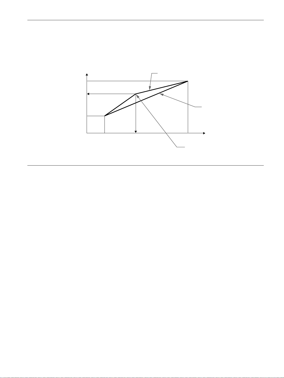
Automatic brightness adjustment function (light sensor)
This monitor is provided with a feature to automatically adjust the screen brightness according to the brightness of the surroundings. The
brightness of the backlight is set to the most appropriate level by setting the light sensor to ON. The default setting of the brightness of the
backlightis set to its maximum. When the light sensor setting is set to ON, the monitor adjusts the brightness of the backlight linearly from
its lower- to upper-limit values. When the user adjusts the backlight, the backlight brightness is automatically adjusted between the user
adjustment value and the upper- and lower-limit values.
Backlight brightness
Maximum
User adjustment value
Minimum
Brightnessduring
user adjustment
Automatic brightness adjustment
after user adjustment
Automatic picture quality adjustment function
When the monitor receives an input signal, it automatically
matches the signal to one of the factory preset modes stored in the
monitor’s memory to provide a high quality picture at the center
of the screen. (See Appendix for a list of the factory preset
modes.)
For input signals that do not match one of the factory preset
modes, the automatic picture quality adjustment function of this
monitor automatically adjusts the picture position, phase, and
pitch, and ensures that a clear picture appears on the screen for
any timingwithinthemonitor’sfrequency range (horizontal: 30 –
61 kHz, vertical: 48 – 85 Hz).
Consequently, the first time the monitor receives input signals
that do not match one of the factory preset modes, the monitor
may take a longer time than normal for displaying the picture on
the screen. This adjustment data is automatically stored in
memory so that next time, the monitor will function in the same
way as when the monitor receives the signals that match one of
the factory preset modes.
In all modes as above, if the picture is adjusted, the adjustment
data is stored as a user mode and automatically recalled whenever
the same input signal is received.
Note
While the automatic picture quality adjustment function is activated, only
1
(power) switch, and INPUT button will operate.
the
Preset automatic adjustment
Brightness of surroundings
User-specified
brightness value
Note on the adjusting the phase
If the automatic picture quality adjustment function is activated, the
picture moves slightly whenever the monitor receives the input signal,
regardless of the stored adjustment.
18
Troubleshooting
Before contacting technical support, refer to this section.
On-screen messages
If there is something wrong with the input signal, one of the
following messages appears on the screen. To solve the problem,
see “Trouble symptoms and remedies” on page 20.
If CABLE DISCONNECTED appears on the screen
This indicates that the video signal cable has been disconnected
from the currently selected connector.
INFORMATION
CAB L E D I SCONNECTED
INPU T : 1
GO TO POWER SAVE
If OUT OF SCAN RANGE appears on the screen
This indicates that the input signal is not supported by the
monitor’s specifications. Check the following items.
INFORMATION
OUT OF SCAN RANGE
x x . x kHz / x xHz
If “xx.xkHz/xxHz” is displayed
This indicates that either the horizontal or vertical frequency
is not supported by the monitor’s specifications.
The figures indicate the horizontal and vertical frequencies of
the current input signal. The horizontal frequencies above
100 kHz and the vertical frequencies above 100 Hz are
represented by 99.9 kHz and 99 Hz, respectively.
If “RESOLUTION > XGA” is displayed
This indicates that the resolution is not supported by the
monitor’s specifications.
If NO INPUT SIGNAL appears on the screen
This indicates that no signal is input, or that no signal is input
from the currently selected connector.
INPUT:
This indicates the currently selected connector (INPUT: 1 or
INPUT: 2).
GO TO POWER SAVE
The monitor will enter the power saving mode after about 4
seconds from the message is displayed.
GB
INFORMATION
NO INPUT S IGNA L
INPU T : 1
GO TO POWER SAVE
INPUT:
This indicates the currently selected connector (INPUT: 1 or
INPUT: 2).
GO TO POWER SAVE
The m onitor will enter the power saving mode after about 4
seconds from the message is displayed.
19

Trouble symptoms and remedies
If a problem is caused by the connected computer or other equipment, please refer to the connected equipment’s instruction m anual.
Use the self-diagnosis function (page 22) if the following recommendationsdo not resolve the problem.
Symptom Check these items
No picture
If the AC power indicator is not lit • Check that the power cord is properly connected.
If the AC power indicator is red • Check that the 1 (power)switchisinthe“on” position.
The AC power indicator is flashing
red
If the 1 (power) indicator is not lit,
or if the 1 (power)indicator will not
light up when the 1 (power) switch
is pressed
If the 1 (power) indicator is green
or flashing orange
If the 1 (power) indicator is
alternating between green and
orange
If CABLE DISCONNECTED
appears on the screen
If NO INPUT SIGNAL appears on
the screen, or the 1 (power)
indicator is orange
If OUT OF SCAN RANGE appears
on the screen
If using Windows • If you replaced an old monitor with this monitor, reconnect the old monitor and do the
If using a Macintosh system • Check that the Macintosh adapter (not supplied) and the video signal cable are properly
• Check that the system connecting cable is properly connected and all plugs are firmly
seated in their sockets (page 8).
• Press the AC power switch twice to turn the monitor off and then on.
• Check that the 1 (power)switchisinthe“on” position.
• CheckthattheACpowerswitchisinthe“on” position.
• Check that the system connecting cable is properly connected and all plugs are firmly
seated in their sockets (page 8).
• Use the self-diagnostics function (page 22).
• The monitor cannot return from low power consumption mode because the user sensor
fails to detect the presence of a user. Press the 1 (power) switch twice to turn the monitor
off and then on. If you set the user sensor to OFF, the monitor does not enter low power
consumption mode (page 16).
• Check that the video signal cable is properly connected and all plugs are firmly seated in
their sockets (page 8).
• Checkthat the input select setting is correct (page 10).
• Check that the video input connector’s pins are not bent or pushed in.
• A non-supplied video signal cable is connected. If you connect a non-supplied video
signal cable, CABLE DISCONNECTED appears on the screen before entering the power
saving mode. This is not a malfunction.
• Check that the video signal cable is properly connected and all plugs are firmly seated in
their sockets (page 8).
• Checkthat the input select setting is correct (page 10).
• Check that the video input connector’s pins are not bent or pushed in.
xProblems caused by the connected computer or other equipment
• The computer is in the power saving mode. Try pressing any key on the keyboard or
moving the mouse.
• Check that the computer’spoweris“on.”
xProblems caused by the connected computer or other equipment
• Check that the video frequency range is within that specified for the monitor. If you
replaced an old monitor with this monitor, reconnect the old monitor and adjust the
frequency range to the following:
Horizontal: 30 – 61 kHz, Vertical frequency: 48 – 85 Hz (only XGA mode at 75 Hz)
following.Install the WindowsMonitor Information Disk (page 9) and select this monitor
(“SDM-N50R”) from among the Sony monitors in the Windowsmonitor selection screen.
connected.
20
Symptom Check these items
Picture flickers, bounces,
oscillates, or is scrambled
Picture is fuzzy • Adjust the brightness and contrast (page 12).
Picture is ghosting • Eliminate the use of video cable extensions and/or video switch boxes.
Picture is not centered or sized
properly
Picture is too small • Set the zoom setting to ON (page 14).
Wavy or elliptical pattern (moire)
is visible
Color is not uniform • Adjust the pitch and phase (page 13).
White does not look white • Adjust the color temperature (page 14).
Monitor buttons do not operate
( appears on the screen)
The monitor turns off after a while • SetthepowersavingfunctiontoOFF(page16).
• Adjust the pitch and phase (page 13).
• Isolate and eliminate any potential sources of electric or magnetic fields such as other
monitors, laser printers, electric fans, fluorescent lighting, or televisions.
• Move the monitor away from power lines or place a magnetic shield near the monitor.
• Try plugging the monitor into a different AC outlet, preferably on a different circuit.
xProblems caused by the connected computer or other equipment
• Check your graphics board manual for the proper monitor setting.
• Confirm that the graphics mode (VESA, Macintosh 19" Color, etc.) and the frequency of
the input signal are supported by this monitor (Appendix). Even if the frequency is within
theproperrange,somevideoboardsmayhaveasyncpulsethatistoonarrowforthe
monitor to sync correctly.
• Adjust the computer’s refresh rate (vertical frequency) to obtain the best possible picture.
• Adjust the pitch and phase (page 13).
• Check that all plugs are firmly seated in their sockets.
• Adjust the pitch and phase (page 13).
• Adjust the picture position (page 13). Note that some video modes do not fill the screen to
the edges.
xProblems caused by the connected computer or other equipment
• Set the computer’sresolutiontothescreen’s resolution.
• Adjust the pitch and phase (page 13).
• If the menu lock is set to ON, set it to OFF (page 16).
• Set the user sensor to OFF (page 16).
GB
xProblems caused by the connected computer or other equipment
• Set the computer’s power saving setting to off.
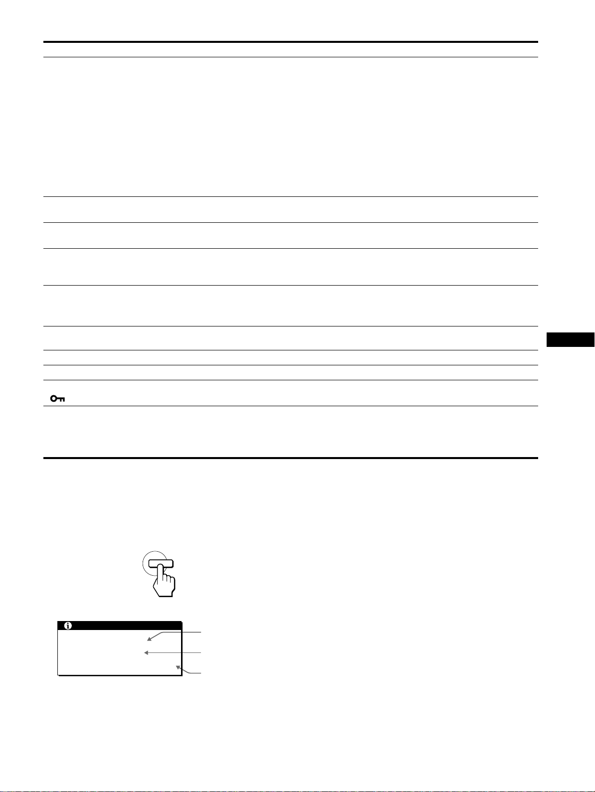
Displaying this monitor’s name, serial number,
and date of manufacture
While the monitor is receiving a video signal, press and hold the
MENU button for more than 5 seconds to display this monitor’s
information box.
MENU
Example
INFORMATION
MODEL : SDM-N50R
SER NO : 1234567
MANUFACTURED : 2001-52
Model name
Serial number
Week and year
of manufacture
If any problem persists, call your authorized Sony dealer and give
the following information:
• Modelname: SDM-N50R
• Serial number
• Name and specifications of your computer and graphics board
21

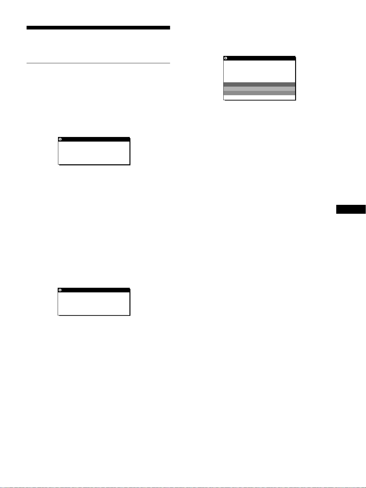
Self-diagnosis function
Thismonitorisequippedwithaself-diagnosisfunction. If there is
a problem with your monitor or computer(s), the screen will go
blank and the 1 (power) indicator will either light up green or
flash orange. If the 1 (power) indicator is lit in orange, the
computer is in power saving mode. Try pressing any key on the
keyboard or moving the mouse.
1 (power)
indicator
If the 1 (power) indicator is green
1
Turn off the AC power switch and disconnect the
video signal cables from the INPUT1 and INPUT2
connectors of the media engine.
2
Pressthe AC power switch twicetoturn the monitor
off and then on.
If all four color bars appear (white, red, green, blue), the monitor
is working properly. Reconnect the video input cables and check
the condition of your computer(s).
If the color bars do not appear, there is a potential monitor failure.
Inform your authorized Sony dealer of the monitor’s condition.
If the 1 (power) indicator is flashing orange
Pressthe 1 (power)switchtwice to turn the monitor off
and then on.
If the 1 (power) indicatorlightsup green,the monitor is working
properly.
If the 1 (power) indicator is still flashing, there is a potential
monitor failure. Count the number of seconds between orange
flashes of the 1 (power) indicator and inform your authorized
Sony dealer of the monitor’s condition. Be sure to note the model
name and serial number of your monitor. Also note the make and
model of your computer and graphic board.
Specifications
LCD panel Panel type: a-Si TFT Active Matrix
Picture size: 15 inch (38 cm)
Input signal format RGB operating frequency*
Horizontal: 30 – 61 kHz
Vertical: 48 – 85 Hz
(only XGA mode at 75 Hz)
Resolution Horizontal: Max.1024 dots
Vertical: Max.768 lines
Input signal levels RGB video signal
0.700 Vp-p, 75 Ω, positive
SYNC signal
TTL level, 2 kΩ,
positive or negative
(Separate horizontal and vertical,
or composite sync)
0.3 Vp-p, 75Ω, negative
(Sync on green)
Audio output 2W × 2
Headphones jack Stereo minijack
Accepts impedance of 16 – 48 Ω
AUDIO IN jack Stereo minijack
Accepts impedance of 47 kΩ
Accepts level 0.5 Vrms
Power requirements 100– 240 V, 50 – 60 Hz, 0.55 – 0.3 A
Power consumption Max. 35 W
Operating temperature 5 – 35
Dimensions (width/height/depth)
Mass Display:
Plug & Play DDC2B/DDC2Bi
Accessories See page 8.
* Recommended horizontal and vertical timing condition
• Horizontal syncwidthdutyshouldbemorethan4.8%oftotal
horizontal time or 0.8 µs, whichever is larger.
• Horizontal blanking width should be more than 2.5 µsec.
• Vertical blanking width should be more than 450 µsec.
Design and specifications are subject to change without notice.
°C
Display (upright):
Approx. 356 × 347 × 185 mm
1
(14
Media engine (without stand):
Approx. 45 × 180 × 180 mm
13
(1
Mediaengine(withstand):
Approx. 94 × 185 × 180 mm
3
/4
(3
Approx. 2.7 kg (5 lb 15 oz)
Mediaengine(withstand):
Approx.0.85kg(1lb14oz)
/16
/8
× 13
× 7
× 7
3
3
/4
/8 inches)
× 7
1
1
/8
/8 inches)
× 7
3
1
/8
/8 inches)
× 7
22
Table des matières
Précautions............................................4
Pour exploiter le son clair du haut-parleurstéréo intégré. . . . . . . . . 5
Identification des composants et des commandes. . . . . . . . . . . . . . 6
Installation.....................................8
Etape 1: Raccordez le moteur de médias à votre ordinateur. . . . . . 8
Etape 2: Raccordez l’écran et le moteur de médias . . . . . . . . . . . . 8
Etape 3: Branchezlecâbled’alimentation....................9
Etape 4: Mettez le moniteur et l’ordinateur sous tension . . . . . . . . . 9
Utilisationduhaut-parleurstéréo..........................10
Sélectiondusignald’entrée..............................10
Personnalisationdevotremoniteur................11
Pilotageparmenu......................................11
Réglageducontraste(CONTRASTE)......................12
Réglage du niveau de noir de l’image (LUMINOSITE) . . . . . . . . . . 12
Suppression du scintillement ou du flou (PHASE/HORLOGE). . . . 13
Réglage de la position de l’image
(CENTRAGEH/CENTRAGEV)...........................13
Affichage d’un signal de faible résolution à la résolution en cours
(ZOOM)..............................................14
Réglage de la température des couleurs (COULEUR). . . . . . . . . . 14
Changement de la position du menu (POSITION MENU) . . . . . . . 14
Réinitialisationdesréglages(RESTAUR) ...................15
Réglagesadditionnels(Option) ...........................15
FR
• Macintosh est une marque commerciale
sous licence d’Apple Computer, Inc.,
déposée aux Etats-Unis et dans d’autres
pays.
• Windows
déposée de Microsoft Corporation aux
Etats-Unis et dans d’autres pays.
• IBM PC/AT et VGA sont des marques
commerciales déposées d’IBM
Corporation of the U.S.A.
• VESA et DDC
commerciales de Video Electronics
Standards Association.
ENERGY STAR est une marque
•
déposée aux Etats-Unis.
• Tous les autres noms de produit
mentionnés dans le présent mode
d'emploi peuvent être des marques
commerciales ou des marques
commerciales déposées de leurs
entreprises respectives.
• De plus, les symboles “”et“”ne
sont pas systématiquement mentionnés
dans ce mode d’emploi.
estune marquecommerciale
sont des marques
Spécificationstechniques........................17
Fonction d’économie d’énergie (capteur utilisateur/
moded’économied’énergie) .............................17
Fonction de réglage automatique de la luminosité
(capteurdelumière)....................................18
Fonction de réglage automatique de la qualité de l’image . . . . . . . 18
Dépannage....................................19
Messagesaffichés.....................................19
Symptômesdedéfaillancesetremèdes.....................20
Fonctiond’autodiagnostic................................22
Spécifications..................................22
Appendix.......................................i
Presetmodetimingtable ..................................i
TCO’95Eco-document....................................i
3
Précautions
Avertissement sur les connexions d’alimentation
• Utilisezle câble d’alimentation fourni. Si vous utilisez un câble
d’alimentation différent, assurez-vous qu’il est compatible
avec la tension secteur locale.
Pour les clients aux Etats-Unis
Si vous n’employez pas le câble approprié, ce moniteur ne sera
pas conforme aux normes FCC obligatoires.
Pour les clients au Royaume-Uni
Si vous utilisez le moniteur au Royaume-Uni, veuillez utiliser
le câble d’alimentation adapté au Royaume-Uni.
Exemples de types de fiches
pour 100 à 120 V CA pour 200 à 240 V CA pour 240 V CA
uniquement
L’appareil doit être installéàproximité d’une prise de courant
aisément accessible.
Installation
N’installez pas et ne laissez pas le moniteur:
• A des endroits exposés à des températures extrêmes, par
exemple à proximité d’un radiateur, d’un conduit de chauffage
ou le rayonnement direct du soleil. L’exposition du moniteur à
des températures extrêmes, comme dans l’habitacle d’une
voiture parquée en plein soleil ou à proximité d’un conduit de
chauffage, risque d’entraîner des déformations du châssis ou
des dysfonctionnements.
• A des endroits soumis à des vibrations mécaniques ou à des
chocs.
• Aproximité d’appareils générant de puissants champs
magnétiques, comme un téléviseur ou d’autres appareils
électroménagers.
• Ades endroit soumis à des quantités inhabituelles de poussière,
de saletés ou de sable, par exemple à côté d’une fenêtre ouverte
ou d’une porte donnant sur l’extérieur. En cas d’installation
temporaire à l’extérieur, veillez à prendre les précautions
requises contre la poussière et les saletés en suspension dans
l’air. Faute de quoi des dommages irréparables risquent de se
produire.
Manipulation d e l’écran LCD
• Ne laissez pas l’écran LCD face au soleil, car vous risquez
sinon de l’endommager. Faites donc attention si vous installez
le moniteur à côté d’une fenêtre.
• N’appuyez pas sur et veillez à ne pas érafler la surface de
l’écran LCD. Ne posez pas d’objets lourds sur l’écran LCD.
Vous risquez sinon d’altérer l’uniformité de l’écran ou de
provoquer un dysfonctionnement de l’écran LCD.
• Lorsquele moniteur est employé dans un environnement froid,
il est possible qu’une image rémanente apparaisse sur l’écran.
Il ne s’agit pas d’un dysfonctionnement. L’écran recouvre sa
condition normale dès que la température est revenue à un
niveau normal.
• Siune image fixe reste affichée pendant une longue durée, il se
peut qu’une image rémanente apparaisse pendant un certain
temps. Cette image rémanente finira par disparaître.
• Le panneau LCD s’échauffe en cours d’utilisation. Il ne s’agit
pas d’un dysfonctionnement.
Remarque sur l’affichage à cristaux liquides
(LCD - Liquid Crystal Display)
Veuillez noter que l’écran LCD est issu de technologie
de haute précision. Toutefois, il est possible que des
points noirs ou des points lumineux (rouge, bleu ou
vert) apparaissent constamment sur l’écran LCD, ainsi
que des bandes de couleur irrégulières ou une certaine
luminosité.Ilnes’agit pas d’un dysfonctionnement.
(Points effectifs: plus de 99,99%)
Entretien
• Débranchez le câble d’alimentationde la prise secteur avant de
procéder au nettoyage de votre moniteur.
• Nettoyezl’écranLCD avec un chiffon doux. Si vous utilisez un
liquide de nettoyage pour le verre, n’utilisez pas de nettoyant
contenant une solution antistatique ou tout autre additif
similaire, car vous risquez sinon de griffer le revêtement de
l’écran LCD.
• Nettoyez le châssis, le panneau et les commandes à l’aide d’un
chiffondouxlégèrement imprégné d’une solution détergente
neutre. N’utilisez aucun type de tampon abrasif, de poudre à
récurer ou de solvant tel que de l’alcool ou de la benzine.
• Ne frottez pas, ne touchez pas et ne tapotez pas la surface de
l’écran avec des objets pointus ou abrasifs comme un stylo à
bille ou un tournevis. Ce type de contact risque de rayer le tube
image.
• Sachezqu’une détériorationdesmatériauxoudurevêtement de
l’écran LCD risque de se produire si le moniteur est exposéà
des solvants volatiles comme des insecticides ou en cas de
contact prolongé avec des objets en caoutchouc ou en vinyle.
Transport
• Débranchez tous les câbles du moniteur avant de le transporter.
Pour transporter cet écran, saisissez-le fermement des deux
mains au niveau du support etde la base. Utilisez égalementles
deux mains pour transporter le moteur de médias. Si vous
laissez tomber le moniteur, vous risquez de vous blesser ou
d’endommager le moniteur.
• Pour transporter ce moniteur en vue de réparations ou de son
expédition, utilisez le carton et les matériaux de
conditionnement originaux.
Remplacement du tube fluorescent
Un tube fluorescent de conception spéciale est installé dans ce
moniteur comme source lumineuse. Si l’écran s’assombrit, est
instableou ne s’allume pas, remplacez le tube fluorescent. Pour le
remplacementdu tube fluorescent, consultez votre revendeur
Sony.
Elimination d u moniteur
• N’éliminez pas ce moniteur avec les ordures
ménagères.
• Letube fluorescent utilisé dans ce moniteur contient
du mercure. L’élimination de ce moniteur doit être
effectuée conformément aux réglementations des
autoritéslocalescompétentesenmatièrede propreté
publique.
4
Réglage de l’inclinaison et de la hauteur
Cet écran peut être ajusté suivant les angles illustrés ci-dessous.
90°
Pour utiliser l’écran confortablement
Cet écran est conçudemanière à ce que vous puissiez le régler
suivant un angle de visualisation confortable. Ajustez l’angle de
visualisationde votre écran en fonction de la hauteur du bureau et
de votre chaise et de manière à ce que l’écran ne vous réfléchisse
pas la lumière dans les yeux.
Pour exploiter le son clair du haut-
40°
50°
Pour ajuster les angles, saisissez le panneau LCD des deux mains
par le bord inférieur comme illustré ci-dessous. Basculez le
panneau LCD vers l’arrière, puis soulevez panneau LCD à la
hauteurd’écran voulue et ajustez-en ensuite l’inclinaison.Lorsdu
réglagedelahauteuretdel’inclinaison, procédezdefaçon lente
et délicate en veillant à ne pas cogner le panneau LCD contre le
bureau ou la base du support d’écran.
50°
parleur stéréointégré
Cet écran est équipé d’un haut-parleur stéréointégré dans la base
du support d’écran.
Nousvousconseillons de positionnerlepanneauLCD légèrement
à l’écart du support d’écran. Les aiguës diffusées par les hautparleurs risquent d’être étouffées par le panneau LCD s’il est
positionné directement au-dessus du support. Veillez à ne pas
laissertomberd’objets métalliques dans les ouïes des hautparleurs, car les haut-parleurs génèrent un champ magnétique.De
même, le champ magnétiquerisqued’affecter les données
enregistrées sur des bandes magnétiques et des disquettes. Veillez
à conserver les appareils d’enregistrement magnétique, les
cassettes et les disquettes à l’écart des ouvertures du haut-parleur.
Un conduit est présent à l’arrière du support d’écran afin
d’accentuer les graves. Veillez à ne pas obstruer ce conduit avec
du papier ou tout autre objet de manière à garantir un son clair.
FR
m
Conduits
Ecartez légèrement
le panneau LCD de
la base.
Haut-parleur
5
Identification des composants et
des commandes
Pour plus de détails, reportez-vous aux pages entre parenthèses.
Ecran LCD
6 Touches 2 (volume) +/– et M(+)/m(–) (pages 10, 12)
Ces touches activent l’affichage du menu VOLUME et
servent de touches fléchées M(+)/m(–)poursélectionner des
paramètres de menu et effectuer des réglages.
7 Touche INPUT (entrée) et OK, et indicateur
(pages 10, 12)
Cettetouchesélectionne le signal d’entréevidéo INPUT 1 ou
INPUT 2 (connecteurs HD15 (RVB)). Le signal d’entréeet
l’indicateur d’entrée correspondant changent chaque fois que
vous appuyez sur cette touche.
Cettetouchesert également de touche OK lorsque le menu est
affichéàl’écran.
MENU
INPUT
1
2
OK
Avant Arrière
SYSTEM CONNECTER
1 Commutateur et indicateur 1 (alimentation)
(pages 9, 17, 22)
Ce commutateur sert à la mise sous et hors tension de l’écran.
L’indicateur s’allume en vert lorsque le moniteur est sous
tension. L’indicateur clignote en vert et en orange lorsque le
moniteur est en mode de faible consommation énergétique et
s’allume en orange lorsque le moniteur est en mode
d’économie d’énergie.
8 Haut-parleur stéréo (page 10)
Ce haut-parleur diffuse les signaux audio sous forme de sons.
9 Conduits
Ces conduits servent à renforcer les graves du haut-parleur.
0 SYSTEM CONNECTOR (CONNECTEUR DU
SYSTEME) (page 8)
Ce connecteur entre les signaux du moteurde médias lorsque
l’écran et le moteur de médias sont raccordésaumoyende
câble de connexion système.
qa Prise pour casque d’écoute (page 10)
Cette prise sort les signaux audio vers un casque d’écoute.
2 Capteur de luminosité et détecteur d’utilisateur
(pages 16, 17, 18)
Ces capteurs mesurent la luminosité ambiante et détectent la
présence d’un utilisateur face à l’écran. Veillez à ne pas
recouvrir le capteur de papier, etc.
3 Touche MENU (menu) (page 12)
Cettetoucheactivel’affichage du menu principal.
4 Touche 6 (contraste) (page 12)
Cettetoucheactivel’affichage du menu CONTRASTE.
5 Touche 8 (luminosité)(page12)
Cettetoucheactivel’affichage du menu LUMINOSITE.
6
Moteur de médias
SYSTEM CONNECTER
(
)
TO DISPLAY
qg Connecteur 2 d’entrée HD15 (RVB) (INPUT2)
(page 8)
Ce connecteur entre les signaux vidéo RVB (0,700 Vp-p,
positifs) et les signaux SYNC. L’assignation des broches est
la même que pour le connecteur qf.
INPUT 1
AUDIO IN
INPUT 2
qs Prise AUDIO IN (page 10)
Cette prise entre les signaux audio lorsqu’il est raccordéàla
prisedesortieaudiodel’ordinateur ou d’un autre appareil
audio.
qd SYSTEM CONNECTOR (CONNECTEUR DU
SYSTEME) (TO DISPLAY) (page 8)
Ce connecteur sort les signaux du moteur de médias lorsque
l’écran et le moteur de médias sont raccordés au moyen de
câble de connexion système.
qf Connecteur 1 d’entrée HD15 (RVB) (INPUT1)
(page 8)
Ce connecteur entre les signaux vidéo RVB (0,700 Vp-p,
positifs) et les signaux SYNC.
qh Connecteur AC IN (page 9)
Ce connecteur assure l’alimentation secteur du moniteur.
qj Commutateur d’alimentation secteur (page 9)
Ce commutateur sert à la mise sous et hors tension du
moniteur. Lorsque le commutateur d’alimentation secteur est
actionné,l’écran se met automatiquement sous tension.
qk Indicateur d’alimentation secteur (page 17)
Cet indicateur s’allumeenvertlorsquelemoteurdemédias
est sous tension. Cet indicateur s’allume en rouge lorsque
l’écran est hors tension et que le moteur de médias est sous
tension. L’indicateur s’allume en orange lorsque le moniteur
se trouve en mode d’économie d’énergie.
ql Support du moteur de médias
Ce support sert à installer le moteur de médias verticalement.
Attention
Veillez à installer le moteur de média verticalement comme illustréà
gauche. L’installation du moteur de média en position plate risque de
bloquer les ouïes de ventilation et de provoquer un dysfonctionnement.
FR
5 4 3 2
1
678910
1112131415
Broche n° Signal
1 Rouge
2Vert
(Synchronisation sur le vert)
3Bleu
4 ID (masse)
5 Masse DDC*
6 Masse du rouge
7 Masse du vert
8 Masse du bleu
9 DDC + 5V*
10 M asse
11 ID(masse)
12 Données bidirectionnelles (SDA)*
13 Synchronisation H
14 Synchronisation V
15 Horlogededonnées (SCL)*
* DDC (Display Data Channel) est une norme de VESA.
7

Installation
Avant d’utiliser votre moniteur, vérifiez si les accessoires
suivants se trouvent bien dans le carton d’emballage:
• Ecran LCD
• Moteur de médias
• Support du moteur de médias
• Câble d’alimentation
• Câble de connexion système (2 m)
(typedecâble applicable: DP-2)
• Câbledesignalvidéo HD15 (RVB)
• Câble audio (minifiche stéréo)
• Windows Monitor Information Disk/Utility Disk
• Macintosh Utility Disk
• Cartedegarantie
• Ce mode d’emploi
Raccordement à un Macintosh
x
vers le connecteur
INPUT1 ou INPUT2
Etape 1:Raccordez le moteur de
médias à votre ordinateur
Mettezlemoteurdemédias et l’ordinateur hors tension avant de
procéder aux connexions.
Remarque
Ne touchez pas les broches du connecteur du câbledesignalvidéo, car
vous risquez sinon de plier les broches.
Raccordement à un ordinateur IBM PC/AT
x
ou compatible
vers le connecteur
INPUT1 ou INPUT2
vers la sortie vidéo
vers la sortie vidéo
Macintosh
Lorsque vous connectez ce moniteur à un ordinateur Macintosh, utilisez
l’adaptateur Macintosh,si nécessaire. Raccordez l’adaptateur Macintosh
à l’ordinateur avant de brancher le câble.
Câble de signal vidéo
HD15 (RVB) (fourni)
Etape 2:Raccordez l’écran et le
moteur de médias
Mettez l’écran et le moteur de médias hors tension avant de
procéder aux connexions.
vers le SYSTEM
CONNECTOR
(connecteursystème)
de l’écran
vers le SYSTEM
CONNECTOR
(connecteursystème)
du moteur de médias
Ordinateur IBM PC/AT
Ordinateur IBM PC/AT
ou compatible
ou compatible
8
Câble de signal vidéo
HD15 (RVB) (fourni)
Câble de connexion
système (2 m) (fourni)
Attention
Veillez à installer le moteur de média verticalement comme illustré
ci-dessus.L’installationdu moteur de média en position plate risque de
bloquer les ouïes de ventilation et de provoquer un dysfonctionnement.
Remarque
Branchez le câble en le saisissant par la fi che.

Etape 3:Branchez le câble
d’alimentation
Le moteur de médias, l’écran et l’ordinateur étant hors tension,
branchez d’abord le câble d’alimentation au moteur de médias et
ensuite sur une prise secteur.
vers AC IN
vers une prise
secteur
Câble d’alimentation
(fourni)
Etape 4:Mettez le moniteur et
l’ordinateur sous tension
1
Mettezlemoteurdemédias sous tension.
L’écran se met automatiquement sous tension. Les
indicateurs du moteur de médias et de l’écran s’allument en
vert.
Si aucune image n’apparaîtsurl’écran
• Vérifiez si le moniteur est correctement raccordéàl’ordinateur.
• Vérifiez si le moteur de médias est sous tension.
• Si l’ndication PAS ENTREE VIDEO apparaîtsurl’écran,
l’ordinateur est en mode d’économie d’énergie. Essayez
d’appuyersur n’importequelle toucheduclavierou de déplacer
la souris.
• Si CABLE DECONNECT apparaîtsurl’écran, essayez de
changer de signal d’entrée (page 10) et vérifiez que le câble
d’entréevidéoestbranché correctement.
• Si l’indication HORS PLAGE DE BALAYAGE apparaîtsur
l’écran, reconnectez l’ancien moniteur. Réglez ensuite la carte
graphiquede l’ordinateur de façon à cequelafréquence
horizontale soit comprise entre 30 – 61 kHz, et la fréquence
verticaleentre 48 – 85 Hz (uniquement en mode XGA à 75 Hz).
Pour des informations plus détaillées sur les messages à l’écran,
voir “Symptômes de défaillances et remèdes”àla page 20.
Vous n’avez besoin d ’aucun pilote pour ce moniteur
Le moniteur prend en charge la fonction Plug & Play “DDC” et détecte
automatiquement toutes les autres informations relatives au moniteur. Il
n’est pas nécessaire d’installer de pilote pour cet ordinateur.
Lapremière fois que vous mettez votre ordinateur sous tension après avoir
raccordé le moniteur, l’assistant de réglage peut s’afficher sur l’écran.
Dans ce cas, suivez les instructions indiquées sur l’écran. Le moniteur
Plug & Play est automatiquement sélectionné afin que vous puissiez
l’utiliser.
La fréquence verticale devient 60 Hz.
Etant donné que les scintillements sur le moniteur sont discrets, vous
pouvez l’utiliser tel quel. Vous n’avez pas besoin de régler la fréquence
verticale sur une valeur particulièrement élevée.
FR
2
Mettez l’ordinateur sous tension.
L’installation de votre moniteur est à présent terminée. Si
nécessaire, utilisez les commandes du moniteur pour régler
l’image.
Si votre ordinateur ou votre carte graphique rencontre des difficultésde
communicationavec ce moniteur, installezle fichier d’informations de ce
moniteurà l’aide de Windows Monitor Information Disk. Pour obtenir de
plus amples informations sur l’installation, consultez le fichier ReadMe
sur le disque.
9
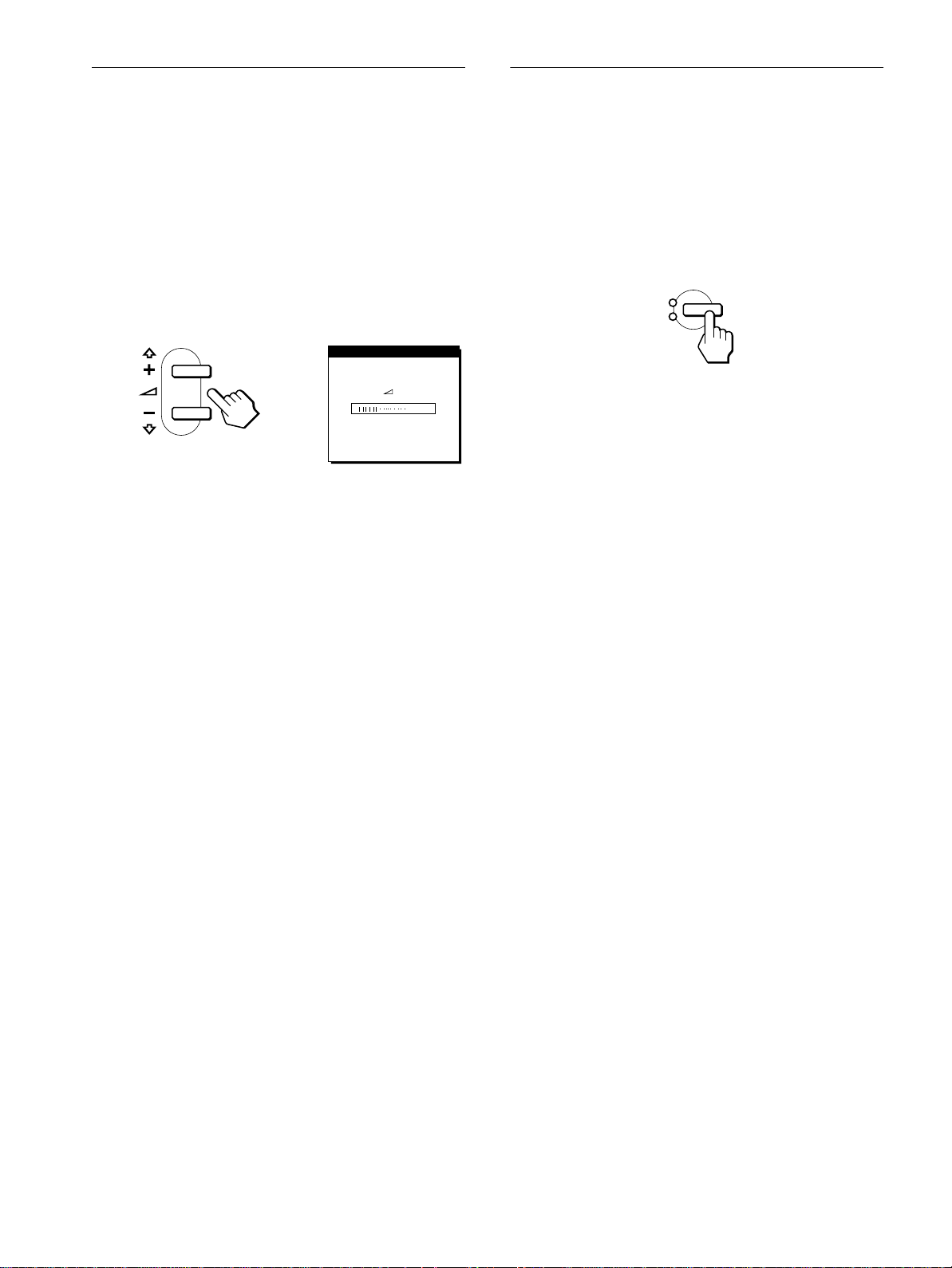
Utilisation du haut-parleur stéréo
Sélection du signal d’entrée
Vous pouvez écouter de la musique, des sons et d’autres fichiers
audio via le haut-parleur stéréo de votre moniteur.
Raccordez la prise AUDIO IN à la prise de sortie audio de votre
ordinateur ou d’un autre appareil audio à l’aide du câble audio
fourni (minifiche stéréo).
Réglage du volume
Le réglage du volume se fait via un menu VOLUME distinct du
menu principal (page 11).
1
Appuyez sur les touches 2 +/–.
Le menu VOLUME apparaîtsurl’écran.
VOL UME
40
2
Appuyez sur les touches 2 +/– pour régler le
volume.
Le menu disparaît automatiquement au bout d’environ
3 secondes.
Vous pouvez raccorder deux ordinateurs à ce moniteur via les
connecteurs INPUT 1 et INPUT 2. Pour sélectionner l’un des
deux ordinateurs, utilisez la touche INPUT.
Appuyez sur la touche INPUT.
Le signal d’entréeetl’indicateur d’entrée correspondant,
“1” (INPUT 1) ou “2” (INPUT 2), changent chaque fois que vous
appuyez sur cette touche.
INPUT
1
2
OK
Remarques
• Vous ne pouvez pas sélectionner le signal d’entrée lorsque le menu
principal est affiché sur l’écran.
• Si aucun signal n’est entré via le connecteur sélectionné,l’indication
PASENTREEVIDEOouCABLE DECONNECT apparaîtsurl’écran.
Au bout de quelques secondes, le moniteur passe en mode d’économie
d’énergie. Si cela se produit, sélectionnezl’autre connecteurà l’aide de
la touche INPUT.
Utilisation de la prise pour casque d’écoute
Vous pouvez écouter les signaux audio de votre ordinateur ou
d’un autre appareil audio à l’aide d’un casque d’écoute.
Raccordezvotre casque d’écoute à la prise pour casque d’écoute.
Le haut-parleur est désactivé dès que vous branchez un casque
d’écoute sur la prise pour casque d ’écoute. Ajustez le volume du
casque d’écoute à l’aide du menu VOLUME.
Remarques
• Vous ne pouvez pas régler le volume lorsque le menu principal est
affiché sur l’écran.
• Lorsque votre moniteur se trouve en mode de faible consommation
énergétique ou en mode d’économie d’énergie,aucun son n’est diffusé
par le haut-parleur.
10
 Loading...