

Page 1
4-077-619-11(1)
TFT LCD Color
Computer Display
Operating Instructions
Mode d’emploi
Bedienungsanleitung
Manual de instrucciones
Istruzioni per l’uso
GB
FR
DE
ES
IT
SDM-N50PS
© 2000 Sony Corporation
Page 2
Owner’s Record
The model and serial numbers are located at the rear of the unit.
Record these numbers in the spaces provided below. Refer to them
whenever you call upon your dealer regarding this product.
Model No.
Serial No.
WARNING
To prevent fire or shock hazard, do not expose the
unit to rain or moisture.
Dangerously high voltages are present inside the
unit. Do not open the cabinet. Refer servicing to
qualified personnel only.
FCC Notice
This equipment has been tested and found to comply with the limits
for a Class B digital device, pursuant to Part 15 of the FCC Rules.
These limits are designed to provide reasonable protection against
harmful interference in a residential installation. This equipment
generates, uses, and can radiate radio frequency energy and, if not
installed and used in accordance with the instructions, may cause
harmful interference to radio communications. However, there is no
guarantee that interference will not occur in a particular installation.
If this equipment does cause harmful interference to radio or
television reception, which can be determined by turning the
equipment off and on, the user is encouraged to try to correct the
interference by one or more of the following measures:
– Reorient or relocate the receiving antenna.
– Increase the separation between the equipment and receiver.
– Connect the equipment into an outlet on a circuit different from
that to which the receiver is connected.
– Consult the dealer or an experi enced radi o/TV techni cian for hel p.
You are cautioned that any changes or modifications not expressly
approved in this manual could void your authority to operate this
equipment.
NOTICE
This notice is applicable for USA/Canada only.
If shipped to USA/Canada, install only a UL LISTED/CSA
LABELLED power supply cord meeting the following
specifications:
SPECIFICATIONS
Plug Type Nema-Plug 5-15p
Cord Type SVT or SJT, minimum 3 × 18 AWG
Length Maximum 15 feet
Rating Minimum 7 A, 125 V
NOTICE
Cette notice s’applique aux Etats-Unis et au Canada
uniquement.
Si cet appareil est export* aux Etats-Unis ou au Canada, utiliser
le cordon d’alimentation portant la mention UL LISTED/CSA
LABELLED et remplissant les conditions suivantes:
SPECIFICATIONS
Type de fiche Fiche Nema 5-15 broches
Cordon Type SVT ou SJT, minimum 3 × 18 AWG
Longueur Maximum 15 pieds
Tension Minimum 7 A, 125 V
E
NERGY STAR Partner, Sony
As an
Corporation has determined that this
product meets the
guidelines for energy efficiency.
E
NERGY STAR
INFORMATION
This product complies with Swedish National Council for Metrology
(MPR) standards issued in December 1990 (MPR II) for very low
frequency (VLF) and extremely low frequency (ELF).
INFORMATION
Ce produit est conforme aux normes du Swedish National Council
for Metrology de décembre 1990 (MPR II) en ce qui concerne les
fréquences très basses (VLF) et extrêmement basses (ELF).
INFORMACIÓN
Este producto cumple las normas del Consejo Nacional Sueco para
Metrología (MPR) emitidas en diciembre de 1990 (MPR II) para
frecuencias muy baj as (VLF) y frecu enci as extr emada mente ba jas (E LF).
This monitor complies with the
TCO’95 guidelines.
If you have any questions about this product, you may call:
Sony Customer Information Center
1-800-222-SONY (7669)
or write to:
Sony Customer Information Center
1 Sony Drive, Mail Drop #T1-11, Park Ridge, NJ 07656
Declaration of Conformity
Trade Name: SONY
Model No.: SDM-N50PS
Responsible Party: Sony Electronics Inc.
Address: 1 Sony Drive, Park Ridge, NJ 07656 USA
Telephone No.: 201-930-6972
This device complies with Part 15 of the FCC Rules. Operation is
subject to the following two conditions: (1) This device may not
cause harmful interference, and (2) this device must accept any
interference received, including interference that may cause
undesired operation.
2
Page 3
Table of Contents
Precautions. . . . . . . . . . . . . . . . . . . . . . . . . . . . . . . . . . . . . . . . . . . . 4
Identifying parts and controls . . . . . . . . . . . . . . . . . . . . . . . . . . . . . . 6
Setup. . . . . . . . . . . . . . . . . . . . . . . . . . . . . . . . . . . . . . . . . .8
Step 1:
Step 2:
Step 3:
Step 4:
Connect the media engine to your computer. . . . . . . . . . . . 8
Connect the display and media engine . . . . . . . . . . . . . . . . 8
Connect the power cord. . . . . . . . . . . . . . . . . . . . . . . . . . . . 9
Turn on the monitor and computer . . . . . . . . . . . . . . . . . . . 9
Installing the display vertically . . . . . . . . . . . . . . . . . . . . . . . . . . . . 10
Using the headphones . . . . . . . . . . . . . . . . . . . . . . . . . . . . . . . . . . 10
Selecting the on-screen menu language (LANGUAGE). . . . . . . . . 11
Selecting the input signal . . . . . . . . . . . . . . . . . . . . . . . . . . . . . . . . 11
Customizing Your Monitor . . . . . . . . . . . . . . . . . . . . . . .12
Navigating the menu. . . . . . . . . . . . . . . . . . . . . . . . . . . . . . . . . . . . 12
Adjusting the contrast (CONTRAST) . . . . . . . . . . . . . . . . . . . . . . . 13
Adjusting the black level of an image (BRIGHTNESS). . . . . . . . . . 13
Eliminating flicker or blurring (PHASE/PITCH) . . . . . . . . . . . . . . . . 14
Adjusting the picture position (H CENTER/V CENTER). . . . . . . . . 14
Displaying a low-resolution signal at the actual resolution
(ZOOM). . . . . . . . . . . . . . . . . . . . . . . . . . . . . . . . . . . . . . . . . . . . . . 15
Adjusting the color temperature (COLOR) . . . . . . . . . . . . . . . . . . . 15
Changing the menu’s position (MENU POSITION) . . . . . . . . . . . . 15
Resetting the adjustments (RESET). . . . . . . . . . . . . . . . . . . . . . . . 16
Additional settings (Option). . . . . . . . . . . . . . . . . . . . . . . . . . . . . . . 16
GB
• Macintosh is a trad emark licensed to
Apple Computer, Inc., registered in the
U.S.A. and other countries.
• Windows
trademarks of Microsoft Corporation in
the United States and other countries.
• IBM PC/AT and VGA are registered
trademarks of IBM Corporation of the
U.S.A.
• VESA and DDC
Video Electronics Standard
Association.
•
E
mark.
•WinPortrait
trademarks of Portrait Displays, Inc.
• All other product nam es m entioned
herein may be the trademarks or
registered trademarks of their respective
companies.
• Furthermore, “” and “” are not
mentioned in each case in this manual.
and MS-DOS are registered
are trademarks of the
NERGY STAR is a U.S. registered
/MacPortrait are the
Technical Features . . . . . . . . . . . . . . . . . . . . . . . . . . . . .17
Power saving function. . . . . . . . . . . . . . . . . . . . . . . . . . . . . . . . . . . 17
Automatic picture quality adjustment function . . . . . . . . . . . . . . . . 17
Troubleshooting. . . . . . . . . . . . . . . . . . . . . . . . . . . . . . . .18
On-screen messages . . . . . . . . . . . . . . . . . . . . . . . . . . . . . . . . . . . 18
Trouble symptoms and remedies . . . . . . . . . . . . . . . . . . . . . . . . . . 19
Self-diagnosis function . . . . . . . . . . . . . . . . . . . . . . . . . . . . . . . . . . 21
Specifications. . . . . . . . . . . . . . . . . . . . . . . . . . . . . . . . . .21
Appendix. . . . . . . . . . . . . . . . . . . . . . . . . . . . . . . . . . . . . . . i
Preset mode timing table . . . . . . . . . . . . . . . . . . . . . . . . . . . . . . . . . .i
TCO’95 Eco-document . . . . . . . . . . . . . . . . . . . . . . . . . . . . . . . . . . . .i
3
Page 4
Precautions
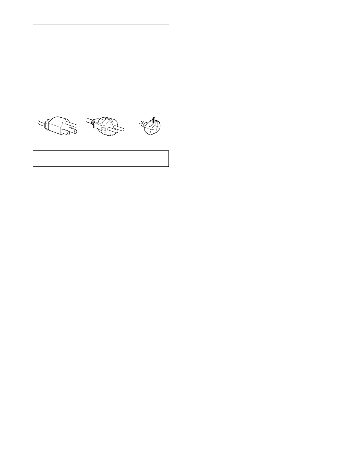
Warning on power connections
• Use the supplied power cord. If you use a different power cord,
be sure that it is compatible with your local power supply.
For the customers in the U.S.A.
If you do not use the appropriate cord, this monitor will not
conform to mandatory FCC standards.
For the customers in the UK
If you use the monitor in the UK, please use the appropriate UK
power cord.
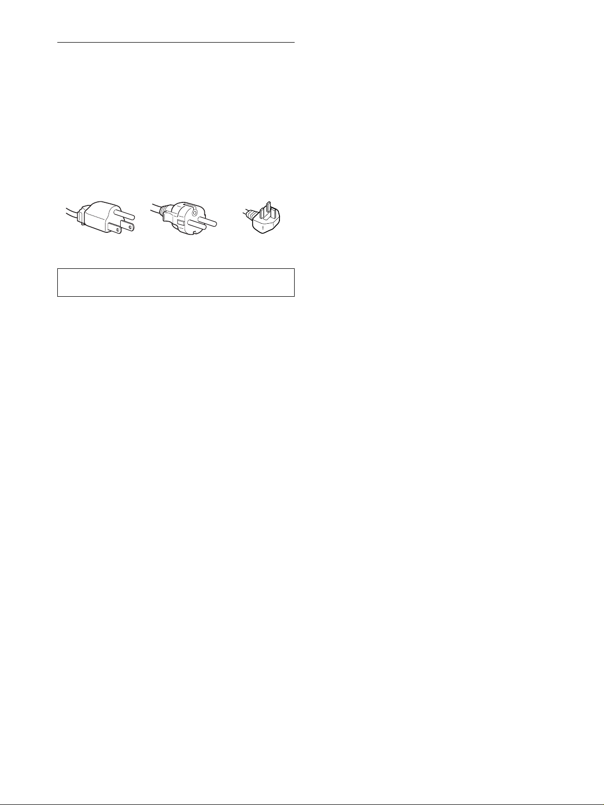
Example of plug types
for 100 to 120 V AC for 200 to 240 V AC for 240 V AC only
The equipment should be in stalled near an easily accessible
outlet.
Installation
Do not install or leave the monitor:
• In places subject to extreme temperature s , for example near a
radiator, heating ve nt, or in direct sunlight. Su bje c tin g the
monitor to extreme temperatures, such as in an automobile
parked in direct sunlight or near a heating vent, could caus e
deformations of the casing or malfunctions.
• In places subject to mechanical vi bration or shock.
• Near any equipment that generates a stron g magnetic field,
such as a TV or various other household appliances.
• In places subject to inordinate amounts of dust, dirt, or sand, for
example near an open window or an outdoor exit. If setting up
temporarily in an outdoor envi ron me n t, be sure to take
adequate precautions against airborne dust and dirt. Otherwise
irreparable malfunctions could occur.
Handling the LCD screen
• Do not leave the LCD screen facing the sun as it can damage
the LCD screen. Take care when you place the monitor by a
window.
• Do not push on or scratch the LCD screen. Do not place a heavy
object on the LCD screen. This may cause the screen to lose
uniformity or cause LCD panel malfunctions.
• If the monitor is used in a cold place, a residual im age may
appear on the screen. This is not a malfunction. The screen
returns to normal as the temperature rises to a normal operating
level.
• If a still picture is displayed for a long time, a residual image
may appear for a while. The residual image will eventually
disappear.
• The LCD panel becomes warm during operation. This is not a
malfunction.
About the bright points of light or black dots
Bright points of light (red, blue or green) or black dots
may appear on the LCD screen. This is not a
malfunction. The LCD screen is made with highprecision technology and more than 99.99% of the
picture element is intact. Howeve r, some of the picture
element may not appea r or some of the picture element
may appear constantly.
Replacement of the fluorescent tube
A specially designed fluorescent tube is installed as the lighting
apparatus for this monitor. If the screen becomes dark, unstable,
or does not turn on, replace the fluorescent tube with a new one.
Consult your Sony dealer when replac ing the fluorescent tube.
Maintenance
• Be sure to unplug the power cord from the power outlet before
cleaning your mon itor.
• Clean the LCD screen with a soft cloth. If you use a glass
cleaning liquid, do not use any type of c leaner containing an
anti-static solution or similar additive as this may scratch the
LCD screen’s coating.
• Clean the cabinet, panel, and controls with a soft cloth lightly
moistened with a mild detergent solution. Do not use any type
of abrasive pad, scouring powder, or solvent, such as alcohol or
benzine.
• Do not rub, touch, or tap the surface of the screen with sharp or
abrasive items such as a ballpoint pen or screwdriver. This type
of contact may result in a scratched pict ure tube.
• Note that material deterioration or LCD screen coating
degradation may occur if the monitor is exposed to volatile
solvents such as insecticide, or if prolonged cont act is
maintained with rubber or vinyl materials.
Transporting
• When transportin g, first disconnect all cables from the m onitor,
then grasp the monitor with both hands to carry it. Be careful
when transporting the monitor, if dropped it may cause injury
or damage.
• When you transport this monitor for repair or shipment, use the
original carton and packing materials.
Disposal of the monitor
• Do not dispose of this monitor with general
household waste.
• The fluorescent tube used in this monitor contains
mercury. Disposal of this mon itor must be carried out
in accordance to the regulations of your local
sanitation authority.
4
Page 5
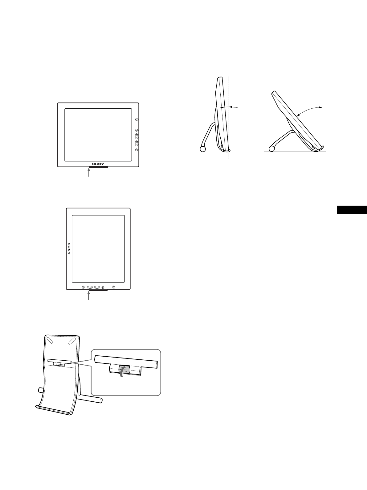
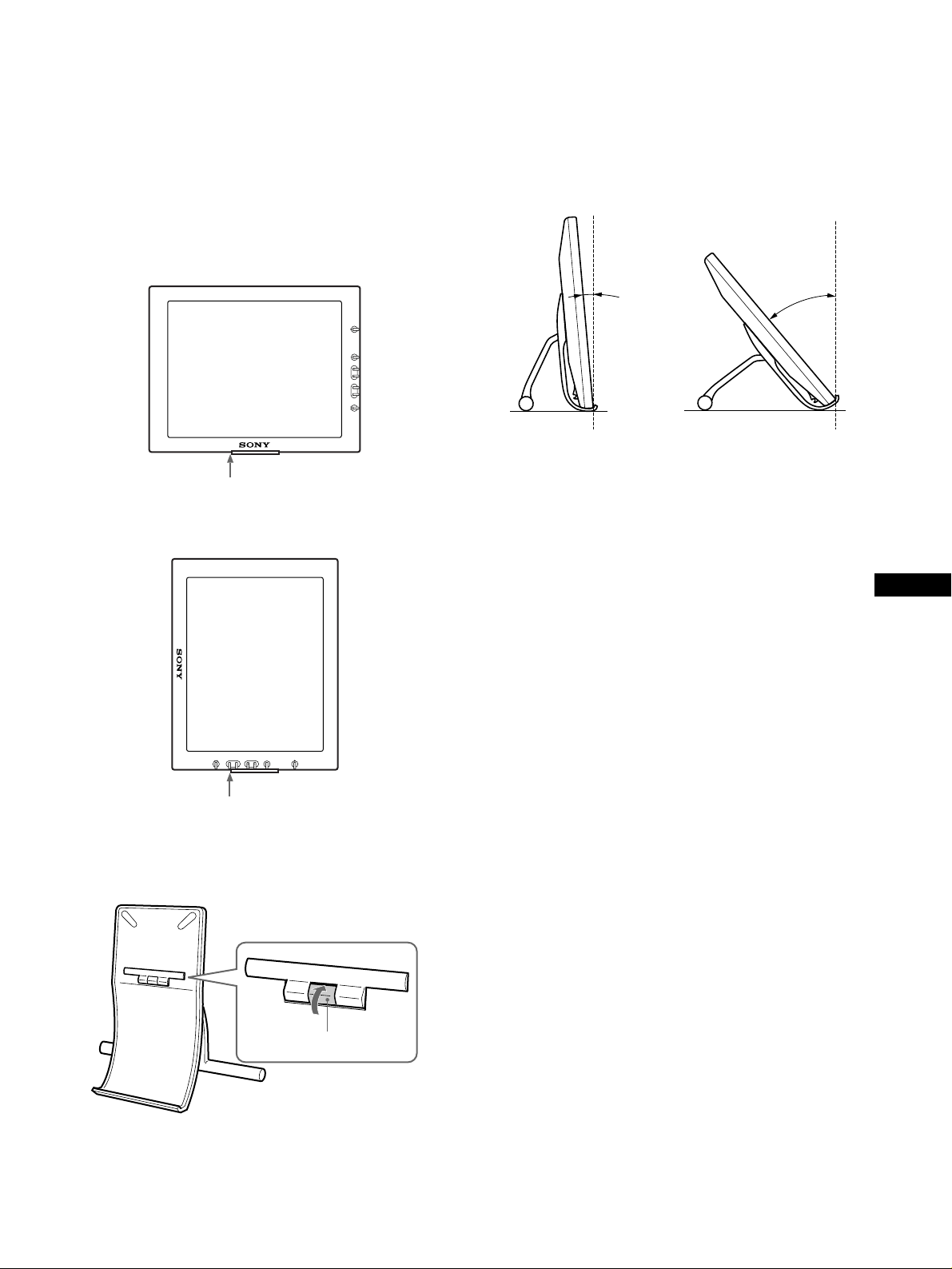
To install the display horizontally or vertically
This display can be installed either horizontally or vertic ally using
the supplied display st and.
Open the display stand until the cli ck soun d is hea r d.
Put the display on the stand, aligning the mark which shows the
stand position on the display.
To switch to the horizontal or vertical viewing position, see
page 10.
Horizontal installation
The stand positioning mark
To adjust the angle
This display can be adjusted within the ang les shown below wit h
the supplied display stand.
To adjust the angle, hold the front base and push (or p ull) the rear
leg outward (or inward) until the desired angle is attained.
To install the display on the display stand, put it softly.
40°
20°
Note
Do not exceed the angles shown above, otherwise the display could fal l
and cause damage or a m alfunction.
Vertical installation
The stand positioning mark
To close the display stand
While sliding the stopper up, close the display stand.
To use the display comfortably
This display is designed so that yo u can se t it up at a comfor table
viewing angle. Adjust the viewing angl e of your display
according to the height of the desk and chair, and so that light is
not reflected from the screen to your eyes.
GB
The stopper
5
Page 6
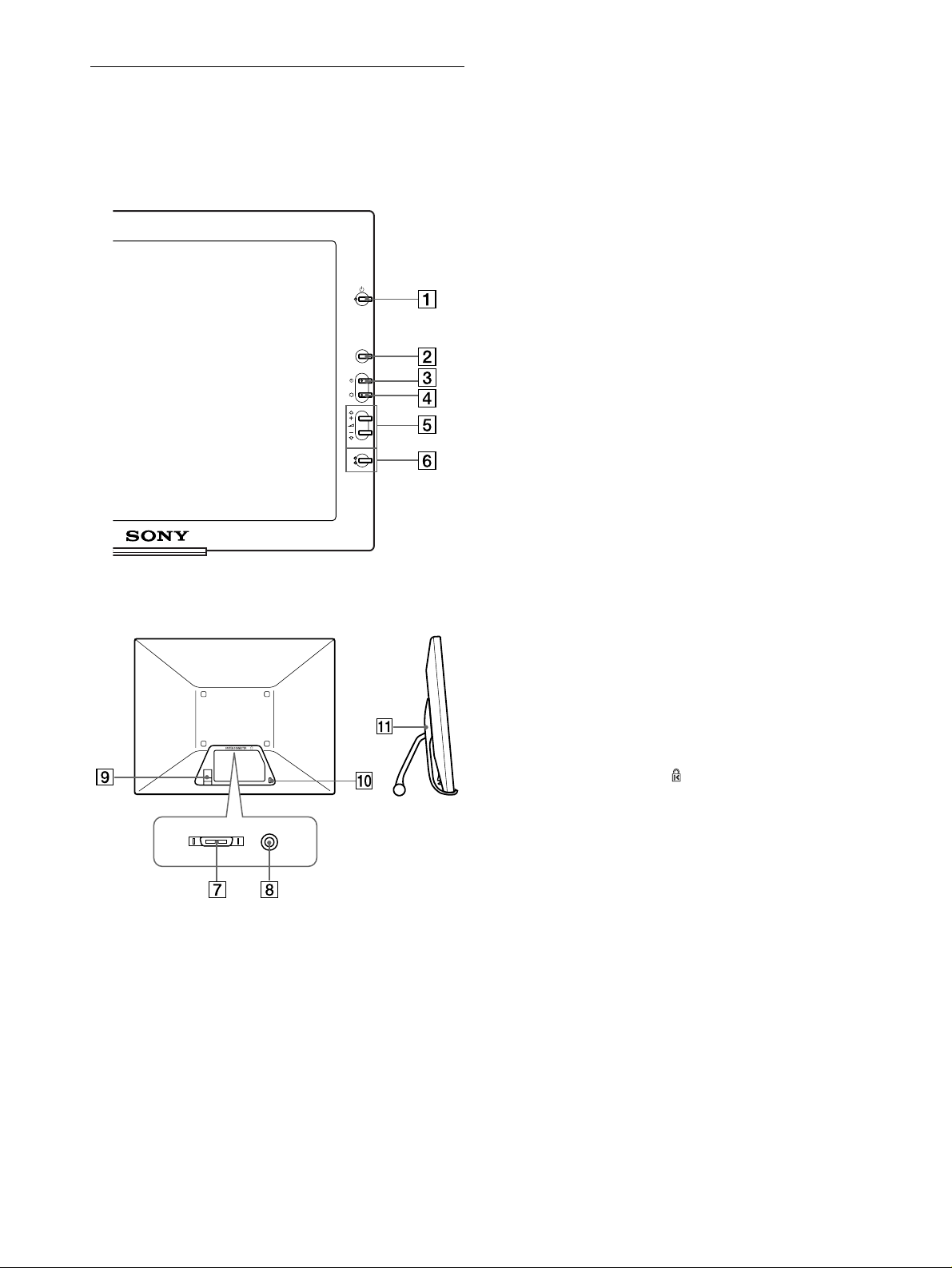
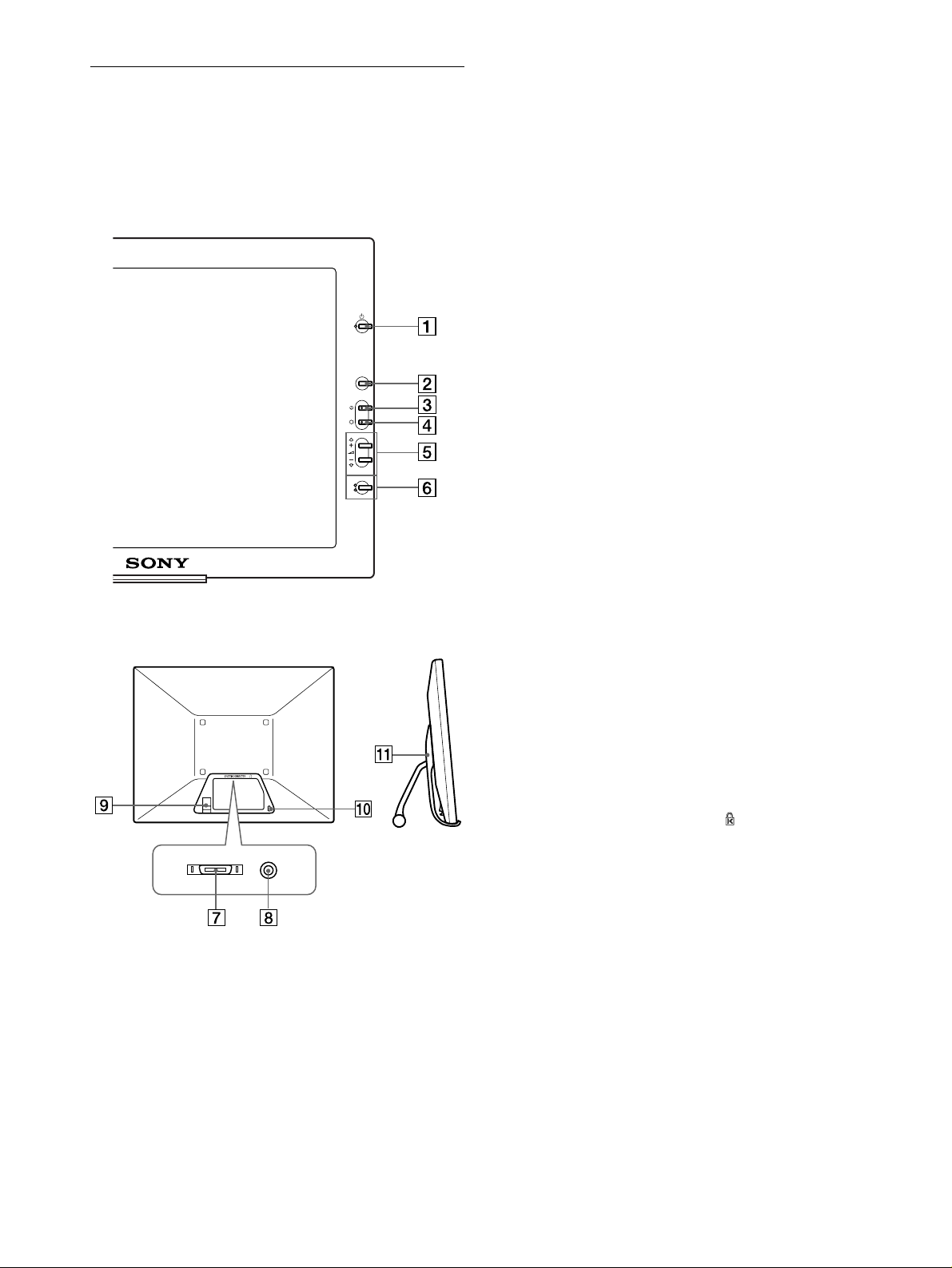
Identifying parts and controls
See the pages in parentheses for further details.
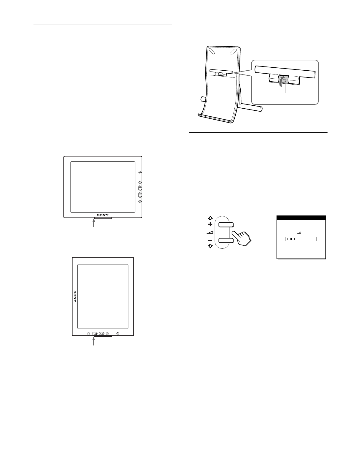
LCD display
1111 1 (Power) switch and indicator (pages 9, 17, 21)
This switc h turns the d isplay on and of f.
The indicator lights up in green when the monitor is turned on.
The indicator lights up in orang e when the monitor is in power
saving mode.
Front
Rear/Side
2222 MENU button (page 13)
This button displays the main menu.
3333 6 (contrast) button (page 13)
This button displays the CONTRAST menu.
4444 8 (brightness) button (page 13)
This button displays the BRITGHTNESS menu.
MENU
5555 2 (volume) +/– and M(+)/m(–) buttons
(pages 10, 13)
These buttons display the VOLUME menu and function as
the M(+)/m(–) buttons when selecting the menu items and
making adjustments.
INPUT
1
2
OK
6666 INPUT and OK button, and indicator (pages 11, 13)
This button selects the INPUT 1 or INPUT 2 video input
signal. The input signal and corresponding input indicator
change each time you press this button.
This button also function s as the OK b utt on whe n displa yi ng
the menu on the screen.
7777 SYSTEM CONNECTOR (page 8)
This connector inputs signals from the media engine when the
display and the media engine are connected with a system
connecting cable.
8888 Headphones jack (page 10)
This jack outputs audio signals to the headphones.
9999 Cable holder
This holder is used to keep the system connecting cable out of
the way.
0000 Security Lock Hole ( )
The security lock hole sho uld be appl ied with the Kensington
Micro Saver Security System.
Micro Saver Security System is a trademark of Kensington.
qa
qa Display stand
qaqa
This stand is used to install the display.
6
Page 7
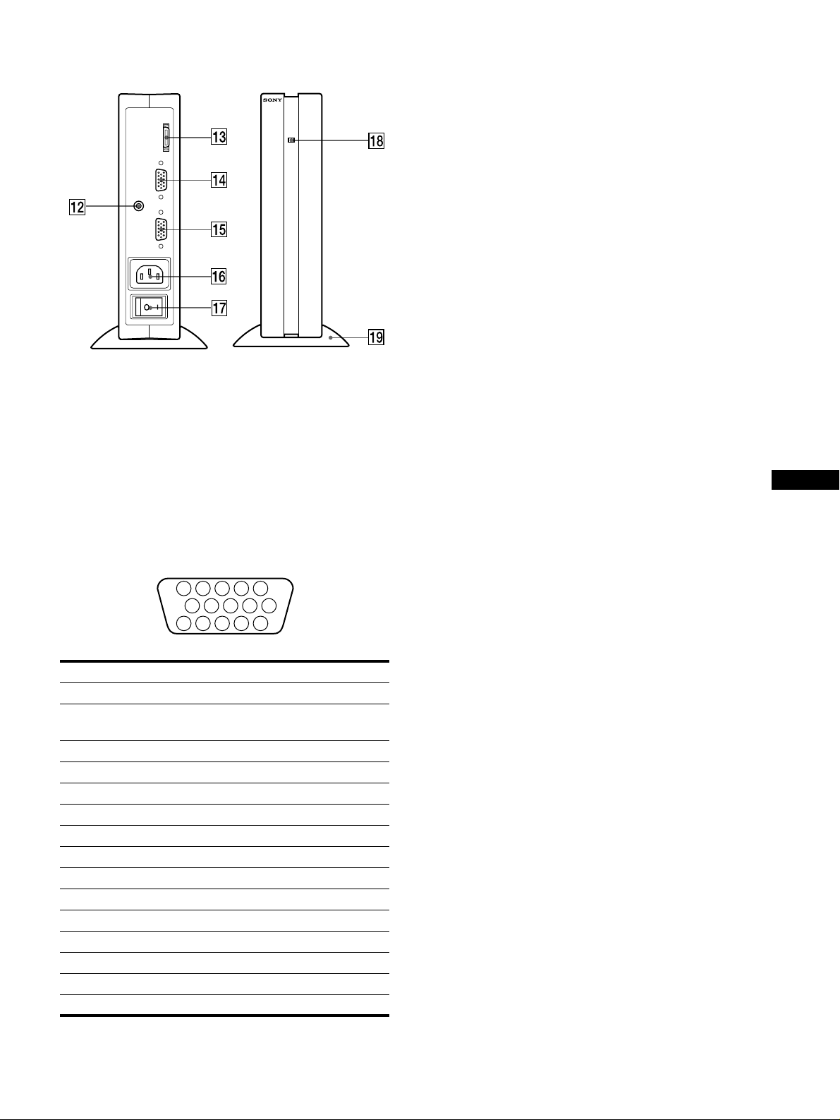
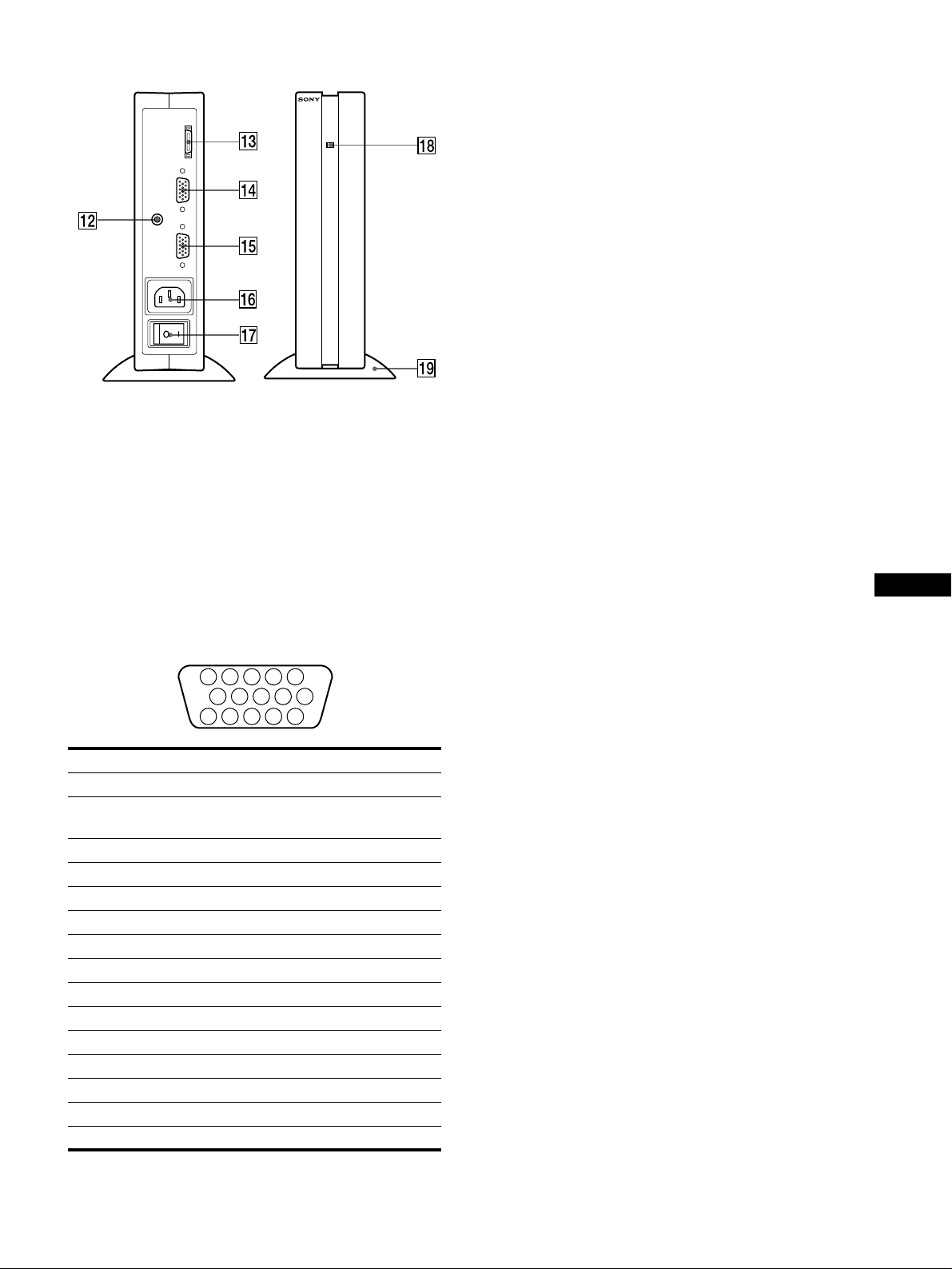
Media engine
SYSTEM CONNECTER
(
)
TO DISPLAY
INPUT 1
AUDIO IN
INPUT 2
qs
qs AUDIO IN jack (page 10)
qsqs
This jack inputs audio signals when connecting to the audio
output jack of the computer or other aud io equipment.
qd
qd SYSTEM CONNECTOR (TO DISPLAY) (page 8)
qdqd
This connector outputs signals to the d isplay when the di splay
and the media engine are connected with a system connecting
cable.
qg
qg HD15 (RGB) input 2 connector (INPUT2) (page 8)
qgqg
This connector inputs RGB video sign als (0.700 Vp-p,
positive) and SYNC signals. The pin assignment is the same
as qf.
qh
qh AC IN connector (page 9)
qhqh
This connector provides AC power to the monitor.
qj
qj AC power switch (page 9)
qjqj
This switch turns the media engine on and off. When the AC
power switch is turned on or off, the display automatically
turns on or off.
qk
qk AC power indicator (page 17)
qkqk
This indicator lights up in green when the media engine is
turned on. The indicator lights up in red when the display is
turned off with the media engine on. The indicator lights u p in
orange when the monitor is in the power saving mode.
ql
ql Media engine stand
qlql
This stand is used to install the media engine vertically.
Caution
Be sure to install the media engine vertically shown as left. Installing the
media engine lying flat may block vent i la tion, and may cause a
malfunction.
GB
qf
qf HD15 (RGB) input 1 connector (INPUT1) (page 8)
qfqf
This connector inputs RGB video signals (0.700 Vp-p,
positive) and SYNC signals.
5 4 3 2
1
678910
1112131415
Pin No. Signal
1Red
2 Green
(Sync on Green)
3Blue
4 ID (Ground)
5 DDC Ground*
6 Red Ground
7 Green Ground
8 Blue Ground
9 DDC + 5V*
10 Ground
11 ID (Ground)
12 Bi-Directional Data (SDA)*
13 H. Sync
14 V. Sync
15 Data Clock (SCL)*
* DDC (Displ ay Data Channel) is a standar d of VE SA.
7
Page 8
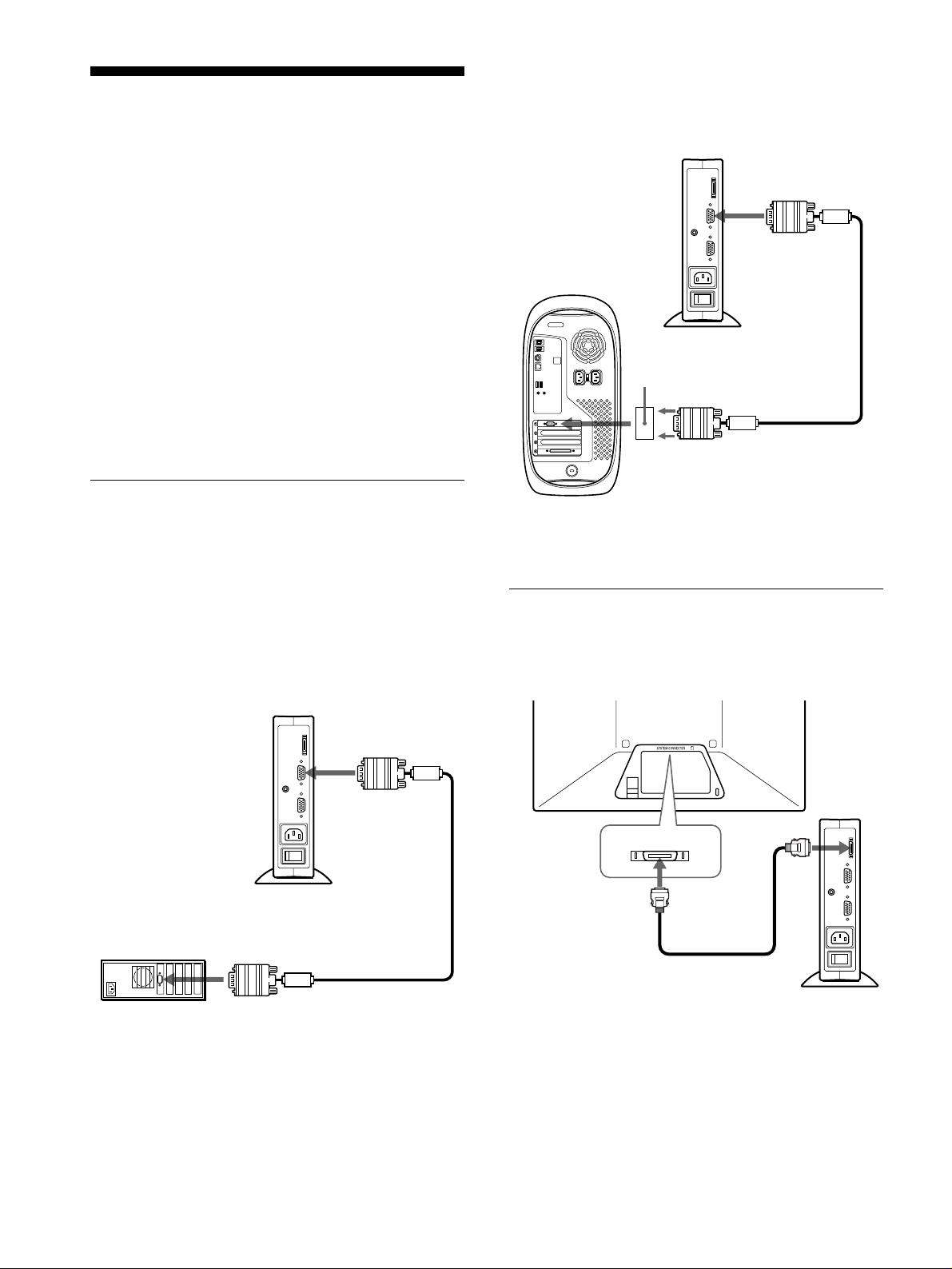
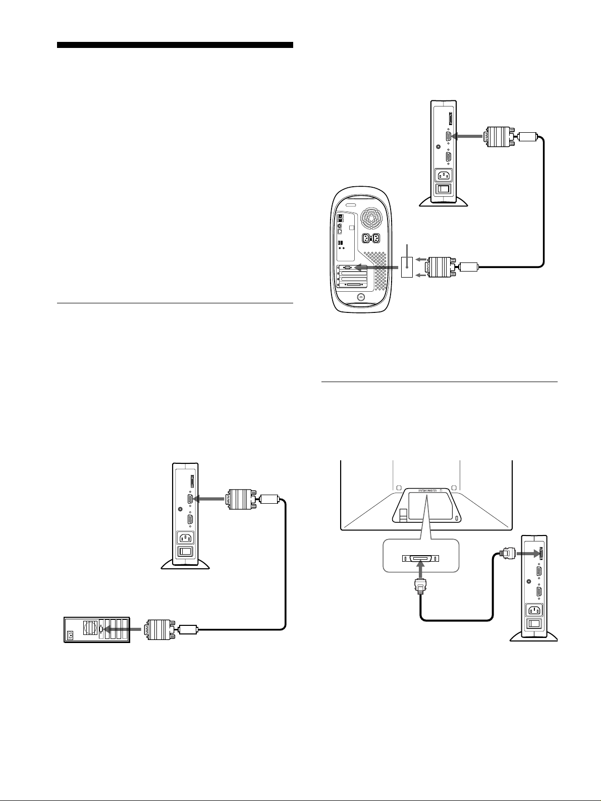
Setup
Use the supplied Macintosh adapter.
to INPUT1 or
INPUT2 connector
Macintosh adapter
(supplied)
*
HD15 (RGB) video
signal cable (supplied)
to video output
Macintosh or
compatible computer
to SYSTEM
CONNECTOR
of the media
engine
system connecting
cable (2 m) (supplied)
to SYSTEM
CONNECTOR of
the display
Before using your monitor, check that t he following accessories
are included in your carton:
• LCD display
• Media engine
•Display stand
• Media engine stand
•Power cord
• System connecting cable (2 m)
(applicable cable type: DP-2)
• HD15 (RGB) video signal cable
• Audio cord (stereo miniplug)
• Macintosh adapter
• Windows Monitor Information Disk/Utility Disk
• Macintosh Utility Disk
• Software for use when installing the display vertically
(WinPortrait/MacPortrait)
• Warranty card
• Notes for Macintosh users
• This instruction manual
Step 1:Connect the media engine
to your computer
Connecting to a Macintosh or compatible
x
computer
Turn off the media engine and computer before connecting.
Note
Do not touch the pins of the video signal cable connector as this might
bend the pins.
Connecting to an IBM PC/A T or compatible
x
computer
IBM PC/AT or
IBM PC/AT or
compatible computer
compatible computer
to video output
* Refe r to the supplied “Notes for Maci nt osh use rs” for further details.
Step 2:Connect the display and
media engine
Turn off the display and media engine before connecting.
to INPUT1 or
INPUT2 connector
HD15 (RGB) video
signal cable (supplied)
Caution
Be sure to install the m ed ia engine vertically shown as ab ove. Installing
the media engine lying flat may block ventilation, and may cause a
malfunction.
Note
Grasp the plug when co nnecting the cable.
8
Page 9
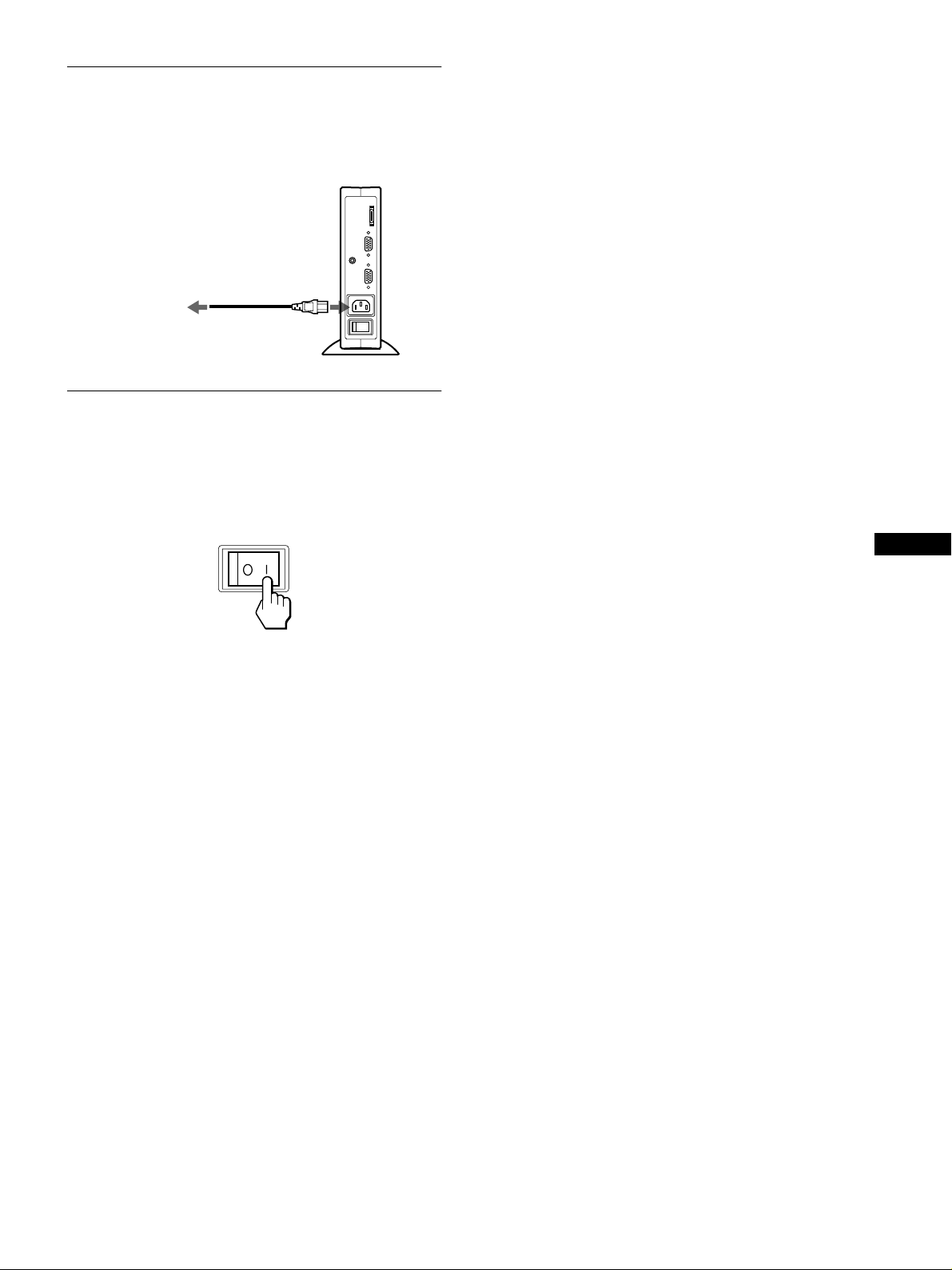
Step 3:Conn ec t the power cord
With the display, media engine, and computer switched off,
first connect the power cord to the media engine, then connect it
to a power outlet.
to AC IN
to a power outlet
power cord (supplied)
Step 4:Turn on the monitor and
computer
1
Turn on the media engine.
The display automatically turns on. The indicators of the
display and media engine light up in green.
If no picture appears on your screen
• Check that the monitor is correctly connected to the computer.
• Check that the medi a en gine is on.
• If NO INPUT SIGNAL appears on the screen, the computer is
in the power saving mode. Try pressing any key on the
keyboard or moving the mouse.
• If CABLE DISCONNECTED appears on the screen, try
changing the input signal (page 11), and check that the video
input cable is properly connected.
• If OUT OF SCAN RANGE appears on the screen, reconnect
the old monitor. Then adjust t he computer’s graphic board so
that the horizontal frequency is between 30 – 61 kHz, and the
vertical frequency is between 48 – 85 Hz (only XGA mode at
75 Hz).
For more information about the on-screen messages, see “Trouble
symptoms and remedi es” on page 19.
For customers using Windows 95/98
To maximize the potential of your monito r, install the new model
information file from the suppl ie d Windows Monitor Information Disk
onto your PC.
This monitor complies with the “VESA DDC” Plug & Play standard. If
your PC/graphics board complies with DDC, select “Plug & Play Monitor
(VESA DDC)” or this monitor’s model name as the monitor type in the
“Control Panel” of Windows 95/98. If your PC/graphics bo ard has
difficulty commu ni ca ti ng wi th this monitor, load the Windows Monitor
Information Disk and sel ec t th is m onitor’s model name as the monitor
type.
GB
2
Turn on the computer.
The installation of your monitor is compl ete. If necessary, use the
monitor’s controls to adjust the picture.
For customers using Windows NT4.0
Monitor setup in Window s NT4. 0 is di ffe rent from Windows 95/98 and
does not involve the sele c ti on of monitor type. Refer to t he W indows
NT4.0 instruction manual for further deta ils on adjusting the re solution,
refresh rate (vertica l fre quency), and number of col ors.
Adjusting the monitor’s resolution and color number
Adjust the monitor’s resolu t io n and color number by referr ing to your
computer’s instruction manual. The color number may vary according to
your computer or graphics board. The color palette setting and the actual
number of co lors are as follows:
• High Color (16 bit) t 65,536 colors
• True Color (24 bit) t about 16.77 million col ors
In true color mode (24 bit ), spee d may be slower.
9
Page 10
Installing the display vertically
The stopper
,
This display can be installed eith er horizontally or vertic ally using
the supplied displ ay stand.
To switch to the horizontal or vertical viewing
position
First install the supplied WinPortrait (for Windws 95/98 and
NT4.0) or MacPortrait (for Macintosh). To switch the view, press
Shift + Ctrl + R on the keyboard. For more information, see the
supplied software’s instruction manual.
To install the display horizontally or vertically
Open the display stand until the click sound is heard.
Put the display on the stand, aligning the mark which shows the
stand position on the display.
Horizontal installation
To close the display stand
While sliding the stopper up, close the display stand.
Using the headphones
You can listen to the audi o signals from your computer or other
audio equipme nt us in g he a dp hones.
Connect the AUDIO IN jack to the audio output jack of your
computer or other audio equipment using the supplied audio cord.
Adjusting the volume
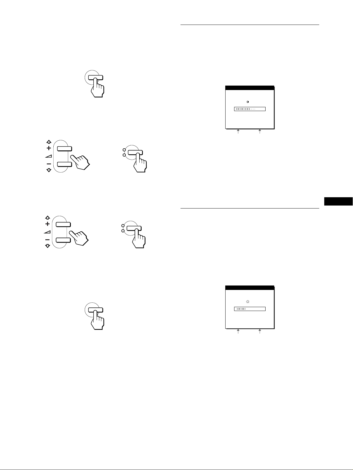
1
Press the 2 +/– buttons.
The VOLUME menu appears on the screen.
The stand positioning mark
Vertical installation
The stand positioning mark
VOLUME
40
2
Press the 2 +/– button to adjust the volume.
The menu automatically disappears after about 3 seconds.
Notes
• You cannot adjust the volum e when displaying the main menu on the
screen.
• When your monitor is in power saving mode, no sound comes from the
headphones.
10
Page 11
Selecting the on-screen menu
Selecting the input signal
language (LANGUAGE)
English, German, French, Spanish, Italian, and Japanese versions
of the on-screen menus are availa ble. The default setting is
English.
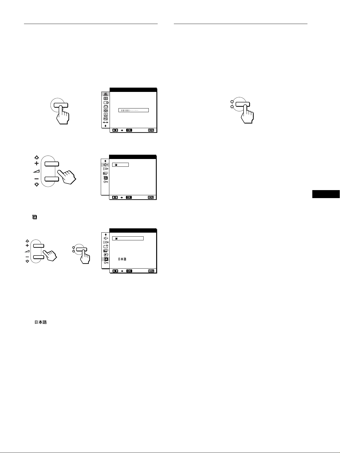
1
Press the MENU button.
PHAS E
MENU
,
2
Press the M(+)/m(–) buttons to select m.
BASS BOOST
ON
OFF
16
EX I T
,
EX I T
You can connect two computers to this monitor using the INPUT
1 and INPUT 2 connectors. To select one of the two computers,
use the INPUT button.
Press the INPUT button.
The input signal and corresponding input indicator, “1” (INPUT
1) or “2” (INPUT 2) chang e eac h time you pres s this button.
INPUT
1
2
OK
Notes
• You cannot select the input signal when displaying the main menu on
the screen.
• If no signal is input to the selected connector, NO INPUT SIGNAL or
CABLE DISCONNECTED appears on the screen. After a few seconds,
the monitor enters the power saving mode. If this ha ppe ns, se l ec t th e
other connector using th e INP UT button.
GB
3
Press the M(+)/m(–) buttons to select
(LANGUAGE) and press the OK button.
LANGUAGE
INPUT
1
2
,,
4
Press the M(+)/m(–) button to select a language.
OK
ENGL I SH
DEUTSCH
FRANÇAI S
ESPAÑOL
ITALIANO
EX I T
• ENGLISH
• DEUTSCH: German
• FRANÇAIS: French
• ESPAÑOL: Spanish
• ITALIANO: Italian
• : Japanese
To close the menu
Press the MENU button once to ret urn t o normal viewing. If no buttons
are pressed, the menu close s automatically afte r about 30 seconds.
11
Page 12
Customizing Your Monitor
Before making adjustments
Connect the monitor and the co mputer, and turn them on.
Wait for at least 30 minutes before making adjustments for the
best result.
4444 V CENTER (page 14)
Select the V CENTER menu
to adjust the picture’s vertical
centering.
VCENTER
25
EXIT
You can make numerous adj ustments to your monitor using the
on-screen menu.
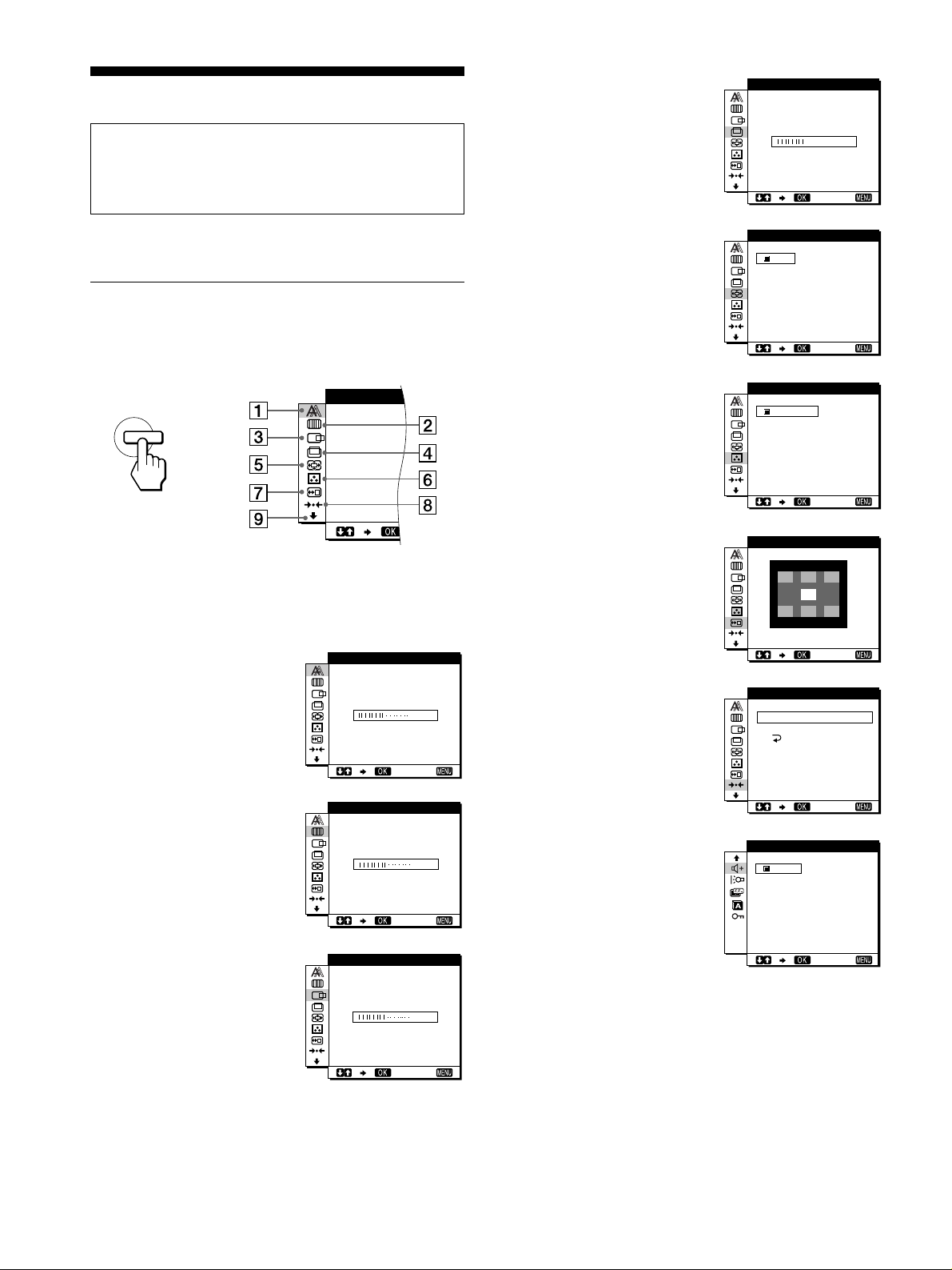
Navigating the menu
Press the MENU button to display th e main menu on your scr een.
See page 13 for more information on using the MENU button.
MENU
PHASE
,
Use the M(+)/m(–) and OK butt ons to sel ect on e of t he follo wi ng
menus. See page 13 for more information on using the
M(+)/m(–) and OK buttons.
1111 PHASE (page 14)
Select the PHASE menu to
adjust the phase when the
characters or pictures appear
fuzzy throughout the entire
screen. Adjust the phase after
adjusting the pitch.
PHAS E
16
EX I T
5555 ZOOM (page 15)
Select the ZOOM menu to
adjust the picture’s size
according to the input
signal’s aspect ratio or
resolution.
6666 COLOR (page 15)
Select the COLOR menu to
adjust the color tone of the
screen.
7777 MENU POSITION
(page 15)
Select the MENU
POSITION to change the onscreen menu position.
8888 RESET (page 16)
Select the RESET menu to
reset the adjustments.
ZOOM
ON
OFF
COLOR
9300 K
0K
650
5000K
USER
ALDJUST
MEN NUP
RESET
S CREEN
ALL
OS I IOT
RESET
EXIT
EX I T
EX I T
RESET
2222 PITCH (page 14)
Select the PITCH menu to
adjust the pitch when the
characters or pictures are
unclear in so me areas of th e
screen.
3333 H CENTER (page 14)
Select the H CENTER menu
to adjust the picture’s
horizontal centering.
12
PITCH
HCENTER
EX I T
50
EX I T
EX I T
9999 Option (page 16)
0
Select m (option) menu to
adjust the monitor’s options.
BASS BOOST
ON
OFF
The options include:
• BASS BOOST
• BACKLIGHT
• POWER SAVE
• LANGUAGE
EX I T
•MENU LOCK
Page 13
Using the MENU, M(+)/m(–), and OK buttons
48.4kHz/ 60Hz
CONTRAST
70
48.4kHz/ 60Hz
B NESSRIGHT
50
x
1
Display the main menu.
Press the MENU button to display the main menu on your
screen.
Adjusting the contrast (CON TRAST)
Contrast adjustment is made using a separate CONTRAST menu
from the main menu (page 12). This setting is stored in memory
for the signal from the currently selected input connector.
MENU
2
Select the menu you want to adjust.
Press the M(+)/m(–) buttons to display the desired menu.
Press the OK button to select the menu item.
INPUT
,
3
Adjust the menu.
Press the M(+)/m(–) buttons to make the adjustment. Then
press the OK button to return to the previous menu.
,
4
Close the menu.
Press the MENU button once to return to normal viewing. If
no buttons are pressed, the menu cl oses automatically after
about 30 seconds.
1
2
OK
INPUT
1
2
OK
1
Press the 6 (contrast) button.
The CONTRAST menu appears on the screen.
Horizontal frequency
of the current input
signal
Displaying the current input signal
The horizontal and vertical frequencies of the current input signal are
displayed in the CONTRAST and BRIGHTNESS menu.
2
Press the M(+)/m(–) buttons to adjust the contrast.
The menu automatically disappears after about 3 seconds.
Vertical frequency of
the current input
signal
Adjusting the black level of an
image (BRIGHTNESS)
Brightness adjustment is made using a separate BRIGHTNESS
menu from the main menu (page 12). This setting is stored in
memory for the signal from the current ly selected input
connector.
1
Press the 8 (brightness) button.
The BRIGHTNESS menu appears on th e screen.
GB
x
You can reset the adjustments using the RESET menu. See
page 16 for more information on resetting the adjustments.
MENU
Resetting the adjustments
Horizontal frequency
of the current input
signal
2
Press the M(+)/m(–) buttons to adjust the
brightness.
The menu automatically disappears after about 3 seconds.
Vertical frequency of
the current input
signal
If the screen is too bright
Adjust the backlight. For more information about adjusting the
backlight see “Adjusting the backlight” on page 16.
Note
You can adjust neit her contrast nor brightness when displaying the main
menu on the screen.
13
Page 14
Eliminating flicker or blurring
(PHASE/PITCH)
When the monitor receives an input signal, the automatic picture
quality function of this monitor is activate d . This functio n
automatically adjusts the phase, pitch, and picture position to
ensure that a clear picture app ears on the screen. For more
information about this function, see “Automatic picture quality
adjustment function” on page 17.
For some input signals, this function may not completely adjust
the phase, pitch, and picture position. In this case, you can
manually set these adjustments according the following
instructions. If you manually set these adj ustme nts, the y are
stored in memory and automatically recalled whenever the
monitor receives the same input signals.
These settings may have to be repeated if you change the input
signal after reconnecting your computer.
1
Set the resolution to 1024
2
Load the Utility Disk.
Use the appropriate disk for y our computer.
For Windows 95/98
Windows Monitor Information Disk/Utility Disk
For Macintosh
Macintosh Utility Disk
3
Start the Utility Disk and display the test pattern.
For Windows 95/98
t
Click [Utility Disk]
For Macintosh
Click [Utility Disk]
4
Press the MENU button.
The main menu appears on the screen.
5
Press the M(+)/m(–) buttons to select (PITCH)
and press the OK button.
The PITCH menu appears on the screen.
[Windows]/[Utility.exe].
t
[SONY-Utility].
768 on the computer.
××××
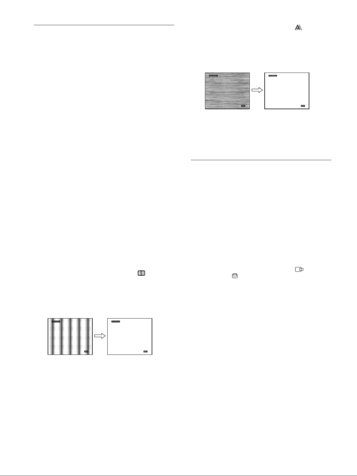
8
Press the M(+)/m(–) buttons to select (PHASE)
and press the OK button.
The PHASE menu appears on the screen.
9
Press the M(+)/m(–) buttons to adjust the phase.
Adjust so that the horizontal stripes are at a minimum.
10
Click [END] on the screen to turn off the test pattern.
To reset the automatic picture quality adjustment
Select SCREEN RESET and a ct iv at e it usin g the RESET menu. See
page 16 for more information on using the RESET menu.
Adjusting the picture position
(H CENTER/V CENTER)
If the picture is not in the center of the screen, adjust the picture’s
centering as follows.
These settings may have to be repeated if you change the input
signal after reconnecting your computer.
1
Start the Utility Disk and display the test pattern.
Repeat steps 2 and 3 of “Eliminating flicker or blurring
(PHASE/PITCH).”
2
Press the MENU button.
The main menu appears on the screen.
3
Press the M(+)/m(–) buttons to select (H
CENTER) or (V CENTER) and press the OK
button.
The H CENTER or V CENTER menu appears on the screen.
6
Press the M(+)/m(–) buttons to adjust the pitch.
Adjust so that the vertical stripes disappear.
7
Press the OK button.
The main menu appears on the screen.
If horizontal stripes are observed over the entire screen, adjust
the phase as the next step.
14
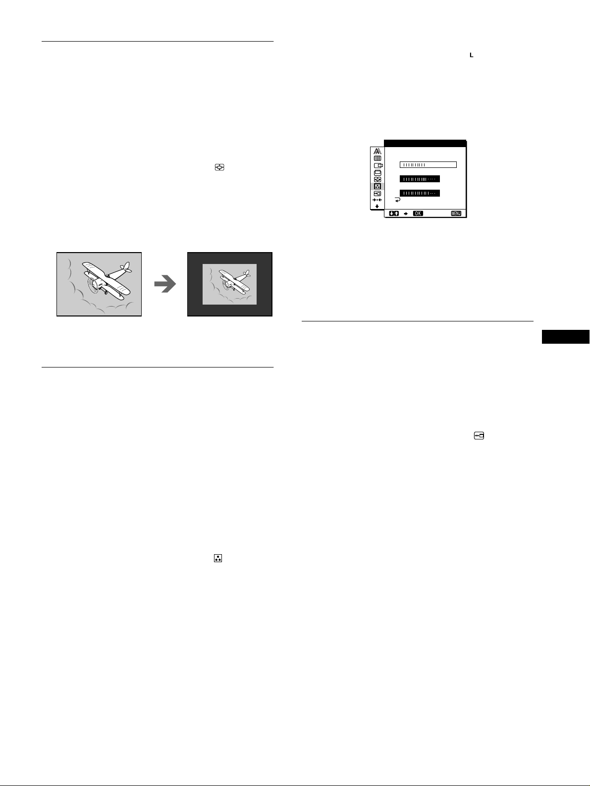
4
Move the picture up, down, left, or right until the
frame at the perimeter of the test pattern
disappears.
Press the M(+)/m(–) buttons to adjust the picture’s
centering using the H CENTER menu for horizontal
adjustment, or the V CENTER menu for vertical
adjustment.
5
Click [END] on the screen to turn off the test pattern.
Page 15
Displaying a low-resolution signal
R168
G170
B175
EX I T
USER AD J UST TMEN
at the actual resolution (ZOOM)
This monitor is preset at the factory to display pictures on the
screen in full, irrespective of the picture’s mode or resolution.
You can also view the picture at its actual resolution.
1
Press the MENU button.
The main menu appears on the screen.
2
Press the M(+)/m(–) buttons to select (ZOOM)
and press the OK button.
The ZOOM menu appears on the screen.
3
Press the m(–) button to select OFF.
The input signal is displayed on the screen at its actual
resolution.
4
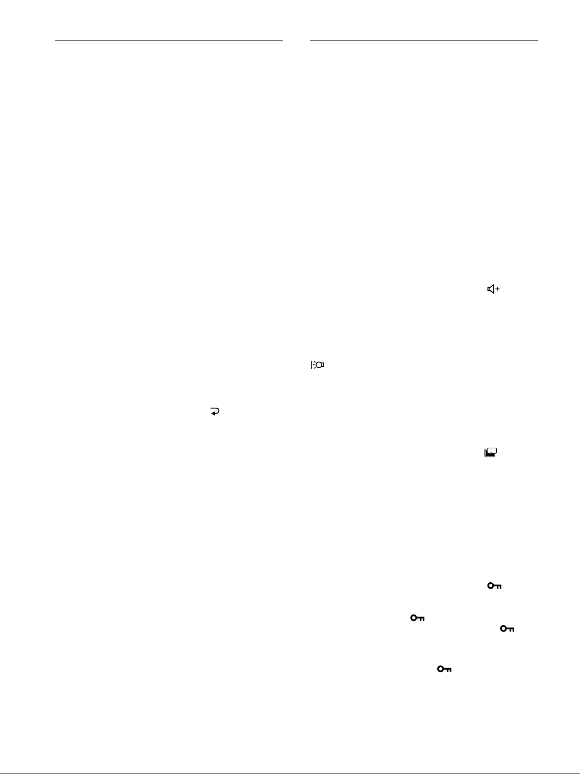
If necessary, fine tune the color temperature.
First press the M(+)/m(–) buttons to select ADJUST and
press the OK button. Then press the M(+)/m(–) buttons to
select R (Red) or B (Blue) and press the OK button, and then
press the M(+)/m(–) buttons to adjust the color temperature.
Since this adjustment ch anges the color temperature by
increasing or decreasing the R and B components with respect
to G (green), the G component is fixed.
If you fine tune the color tempera ture, the new color settin g is
stored in memory for USER ADJUSTMENT and
automatically recalled whenever USER is selected.
The USER ADJUSTMENT setting is common to both the
input signals. If you change t he user adjustment setting for
one input signal, the setting for the other input signal is also
changed.
To display the picture on the screen in full
Select ON in step 3.
Adjusting the color temperature
(COLOR)
The COLOR settings allow you to adjust the picture’s color
temperature by changing the color level of the white color field.
Colors appear reddish if the temperature is low, and bluish if the
temperature is high.
9300K is generally suitable for word processing and other text
oriented applications, and 6500K is generally suitable f or video
images.
You can set the color temperatur e to 5000K, 6500K, 9300K or
user adjustment.
1
Press the MENU button.
The main menu appears on the screen.
2
Press the M(+)/m(–) buttons to select (COLOR)
and press the OK button.
The COLOR menu appears on the screen.
3
Press the M(+)/m(–) buttons to select the desired
color temperature.
The preset color temperatures are 5000K, 6500K, and 9300K.
Since the default setting is 9300K, the whites will change
from a bluish hue to a reddish hue as the temperature is
lowered to 6500K and 5000K.
You can set separate color temperatures for each of the video
input signals.
Changing the menu’s position
(MENU POSITION)
You can change the menu position if it is blocking an image on
the screen.
1
Press the MENU button.
The main menu appears on the screen.
2
Press the M(+)/m(–) buttons to select (MENU
POSITION) and press the OK button.
The MENU POSITION menu appears on the screen.
3
Press the M(+)/m(–) buttons to select the desired
position.
There are three positions each for the top of the screen and the
bottom of the screen, and one for the screen center.
GB
15
Page 16
Resetting the adjustments (RESET)
Additional settings (Option)
You can reset the adjustments.
1
Press the MENU button.
The main menu appears on the screen.
2
Press the M(+)/m(–) buttons to select 0 (RESET)
and press the OK button.
The RESET menu appears on the screen.
You can reset the adjustment data in either of the following
two ways:
Resetting the adjustment data most appropriately
for the current input signal
Press the M(+)/m(–) buttons to select SCREEN RESET
and press the OK button.
The automatic picture q uality adjustment fu nction of this m onitor
automatically adjusts the p hase, pitc h, and pi cture positi on, to the
most appropriate value. If this function is activated, the phase is
automatically adjusted whenever the monitor receives the same
input signal.
The RESET menu is automatically returned to the main menu
after the adjustment data is reset.
Resetting all of the adjustment data for all input
signals
Press the M(+)/m(–) buttons to select ALL RESET and
press the OK button.
The RESET menu is automatically returned to the main menu
after the adjustment data is reset.
You can adjust the foll owi ng options:
• BASS BOOST
• BACKLIGHT
• POWER SAVE
• LANGUAGE
• MENU LOCK
1
Press the MENU button.
The main menu appears on the screen.
2
Press the M(+)/m(–) buttons to select m.
The option menu appears on the screen.
3
Press the M(+)/m(–) buttons to select the desired
option item and press the OK button.
Adjust the selected option item according to the following
instructions.
Boosting the bass (bass boost function)
This option increases the ba ss output.
First press the M(+)/m(–) buttons to select (BASS
BOOST) and press the OK button. Then press the
M(+)/m(–) buttons to select either ON or OFF.
Adjusting the backlight
If the screen is too bright, adjust the backlight.
First press the M(+)/m(–) buttons to select
(BACKLIGHT) and press the OK button. Then press
the M(+)/m(–) buttons to adjust the desired light level.
To cancel resetting
Press the M(+)/m(–) buttons to sel ect and press the
OK button.
The RESET menu returns to the main m enu withou t resetting th e
adjustment data.
Setting up the power saving mode
This monitor has a function which enables it to enter the power
save mode automatically according to the power saving settings
of the computer. You can prevent the monitor from entering the
power saving mode by setting the following option to OFF.
First press the M(+)/m(–) buttons t o select (POWER
SAVE) and press the OK button. Then press the
M(+)/m(–) buttons to select either ON or OFF.
ZZ...
Selecting the on-screen menu language
See “Selecting the on-screen menu language (LANGUAGE)” on
page 11.
Locking the menus and controls (the menu lock
function)
You can protect adj ustment data by locking the menus and
controls.
First press the M(+)/m(–) buttons to select (MENU
LOCK) and press the OK button. Then press the
M(+)/m(–) buttons and select ON.
Only the power switch, and (MENU LOCK) of the option
menu will operate. If any other items a re selected , the mark
appears on the screen.
To cancel the menu lock function
Repeat the procedure above and set and (MENU LOCK) to OFF.
16
Page 17

Technical Features
Power saving function
This monitor meets the power-saving g uide lin es set by VESA, NUTEK, and ENERGY STAR. If the monitor is connected to a computer
or graphics boa rd tha t is DPMS (Display Power Mana gem e nt Sig nalin g ) com p liant, the monitor will au tom a tica lly e nt er th e po wer saving
mode.
Power consumption state Power consumption AC power indicator 1 (po wer) indicato r
normal operation
power saving mode
1 (power): off
AC power: off 0 W off off
W green green
28
W orange orange
≤ 3
Wred off
≤ 3
DPMS defines three power saving states according to the state of
the sync signals supplied from the computer. This monitor’s
power consumption is input at approximately 3 W in all of these
states if the power saving function is set to ON.
When your computer enters in the power saving mode, the input
signal is cut and NO INPUT SIGNAL appears on the screen.
After a few seconds, the monitor enters power saving mode.
Pow er saving
state
suspend (sleep)* horizontal: on / vertical: off
standby (sleep)* horizontal: off / vertical: on
active off (deep sleep)* horizontal: off / vertical: off
* “Sle ep ” a nd “deep sleep” are power savi ng modes defined by the
Environmental Protec t ion Agency.
Note
The power saving function may not work normally if sync signals other
than those listed above are supplied. In such a case, set the power saving
function to OFF.
Automatic picture quality adjustment function
When the monitor receives an input signal, it automatically
matches the signal to one of the factory preset modes stored in the
monitor’s memory to provide a high qual ity picture at the cent er
of the screen. (See Appendix for a list of the factor y preset
modes.)
For input signals that do not matc h one of the factory prese t
modes, the automatic picture quality adjustment function of this
monitor automatically adjusts the phase, pitch, and picture
position, and ensures that a clear picture appears on the screen for
any timing within the monitor’s freq uency range (ho rizontal: 30 –
61 kHz, vertical: 48 – 85 Hz).
Consequently, the first time the monitor receives input signals
that do not match on e of the factory preset modes, the monitor
may take a longer time than normal for displaying the picture on
the screen. This adjustment data is automatically stored in
memory so that next time, the monitor will function in the same
way as when the monitor receives the signals that match one of
the factory preset modes.
In all modes, if the picture is adjusted, the adjustment data is
stored as a user mode and automati cally recalled whenever the
same input signal is received.
Note
While the automatic picture quality adjustment function is activated, only
the power switch, and INPUT button will operate.
Sync signal state
GB
Note on the adjusting the phase
If the automatic picture quality adjustment function is activated, the
picture moves slightly whe n e ver the monitor receive s the input signal,
regardless of the stored adjust m en t.
17
Page 18
Troubleshooting
CAB L E D I SCONNECTED
INPU T : 1
GO TO POWER SAVE
INFORMATION
Before contacting technical support, refer to this section.
On-screen messages
If there is something wrong with the input signal, one of the
following messages appears on the screen. To solve the problem,
see “Trouble symptoms and r e me dies” on pag e19.
If CABLE DISCONNECTED appears on the screen
This indicates that the video signal cable has been disconnected
from the currently selected connector.
If OUT OF SCAN RANGE appears on the screen
This indicates that the input signal is not supported by the
monitor’s specifications. Check the following items.
INFORMATION
OUT OF SCAN RANGE
x x . x kHz / xxHz
If “xx.x kHz/xx Hz” is displayed
This indicates that either the horizontal or vertical frequency
is not supported by the monitor’s specifications.
The figures indicate the horizontal and vertical frequencies of
the current input signal. The horizontal frequencies above
100 kHz and the vertical frequencies above 10 0 Hz are
represented by 99.9 kHz and 99 Hz, respectively.
If “RESOLUTION > XGA” is displayed
This indicates that the resolution is not supported by the
monitor’s specifications.
If NO INPUT SIGNAL appears on the screen
This indicates that no signal is input, or that no signal is input
from the currently selected connector.
INPUT:
This indicates the currently selected connector (INPUT: 1 or
INPUT: 2).
GO TO POWER SAVE
The monitor will enter the power saving mode after about 4
seconds from the message is displaye d.
INPUT:
This indicates the currently selected connector (INPUT: 1 or
INPUT: 2).
GO TO POWER SAVE
The monitor will enter the power saving mode after about 4
seconds from the message is displayed.
18
INFORMATION
NO INPUT S IGNA L
INPU T : 1
GO TO POWER SAVE
Page 19

Trouble symptoms and remedies
If a problem is caused by the connected computer or other equipment, please refer to the connected equip ment’s instruction manual .
Use the self-diagnosis function (page 21) if the following recommendations do not resolve the problem.
Symptom Check these items
No picture
If the media engine’ s AC power
indicator is not lit
If the media engine’ s AC power
indicator is red
The media engine’s AC power
indicator is flashing red
If the display’s 1 (power) indicator
is not lit, or if the 1 (power)
indicator will not light up when the
1 (power) switch is pressed
If the display’s 1 (power) indicator
is green or flashing orange
If CABLE DISCONNECTED
appears on the screen
If NO INPUT SIGNAL appears on
the screen, or the display’s
1 (power) indicator is orange
• Check that the power cord is properly connected.
• Check that the display’s 1 (power) switch is in the “on” position.
• Check that the system connecting cable is properly connected and all p lugs are firmly
seated in their sockets (page 8).
• Press the media engine’s AC power switch twice to turn the monitor off and then on.
• Check that the display’s 1 (power) switch is in the “on” position.
• Check that the media engine’s AC power switch is in the “on” position.
• Check that the system connecting cable is properly connected and all p lugs are firmly
seated in their sockets (page 8).
• Use the self-diagnostics function (page 21).
• Check that the video signal cable is properly connected and all plugs are firmly seated in
their sockets (page 8).
• Check that the input select setting is correct (page 11).
• Check that the video input connector’s pins are not bent or pushed in .
• A non-supplied video signal cable is connected. If you connec t a non-supplied video
signal cable, CABLE DISCONNECTED appears on the screen before entering the power
saving mode. This is not a malfunction.
• Check that the video signal cable is properly connected and all plugs are firmly seated in
their sockets (page 8).
• Check that the input select setting is correct (page 11).
• Check that the video input connector’s pins are not bent or pushed in .
GB
xProblems caused by the connected computer or other equipment
• The computer is in the power saving mode. Try pressing any key on the keyboard or
moving the mouse.
• Check that the computer’s power is “on.”
If OUT OF SCAN RANGE appears
on the screen
If using Windows 95/98 • If you replaced an old monitor with this monitor, reconnect the old monitor and do the
If using a Macintosh system • Check and refer to the supplied “Notes for Macintosh users.”
xProblems caused by the connected computer or other equipment
• Check that the video frequency range is within that specified for the monitor. If you
replaced an old monitor with this monitor, reconnect the old monitor and adjust the
frequency range to the following:
Horizontal: 30 – 61 k Hz
Vertical frequency: 48 – 85 Hz (only XGA mode at 75 Hz)
following. Install the Windows Monitor Information Disk (page 9) and select this monitor
(“SDM-N50PS”) from among the Sony monitors in the Windows 95/98 monitor selection
screen.
(continued)
19
Page 20
Symptom Check these items
The picture does not s witc h to the
vertical view
xProblems caused by the connected computer or other equipment
• Install the supplied WinPortrait (for Windows 95/98 and NT4.0) or MacPortrait (for
Macintosh) (page 10). For more information, see the supplied software’s instruction
manual. If the software does not work properly, contact the software’s customer service.
Picture flickers, bounces,
oscillates, or is scrambled
• Adjust the pitch and phase (page 14).
• Isol ate and eliminate any potential sources of electric or mag netic fields such as other
monitors, laser printers, fluorescent lighting, televisions, or electric fans.
• Move the monitor away from power lines or place a magnetic shield near the monitor.
• Try plugging the monitor into a differe n t AC outlet, preferably on a different circuit.
xProblems caused by the connected computer or other equipment
• Check your graphics board manual for the proper monitor setting.
• C onfirm that the graphics mod e (VESA, Macintosh 19" Color, etc.) and the frequency of
the input signal are su pp ort ed by this monitor (Appendix). Even if the freque n cy is within
the proper range, some graphics boards may have a sync pulse that is too na rrow for the
monitor to sync correctly.
• Adjust the computer’s refresh rate (vertical frequen cy) to obtain the best possible picture.
Picture is fuzzy • A djust the brightness and contrast (page 13).
• Adjust the pitch and phase (page 14).
Picture is ghosting • Eliminate the use of vi deo cable extensions and/or video switch boxes.
• Check that all plugs are firmly seated in thei r so ckets.
Picture is not centered or sized
properly
• Adjust the pitch and phase (page 14).
• Adjust the picture position (page 14). Note that for some input signals or graphics boards,
the picture may not fill the screen to the edges.
The picture is too small • Set the zoom setting to ON (page 15).
xProblems caused by the connected computer or other equipment
• Set the computer’s resolution to the screen’s resolution.
Wavy or elliptical pattern (moire)
• Adjust the pitch and phase (page 14).
is visible
Color is not uniform • Adjust the pitch and phase (page 14).
White does not look white • Adjust the color temperature (page 15).
Monitor buttons do not operate
• If the menu lock is set to ON, set it to OFF (page 16).
( appears on the screen)
The monitor turns off after a while • Set the power saving function to OFF (page 16).
xProblems caused by the connected computer or other equipment
• Set the computer’s power saving setting to off.
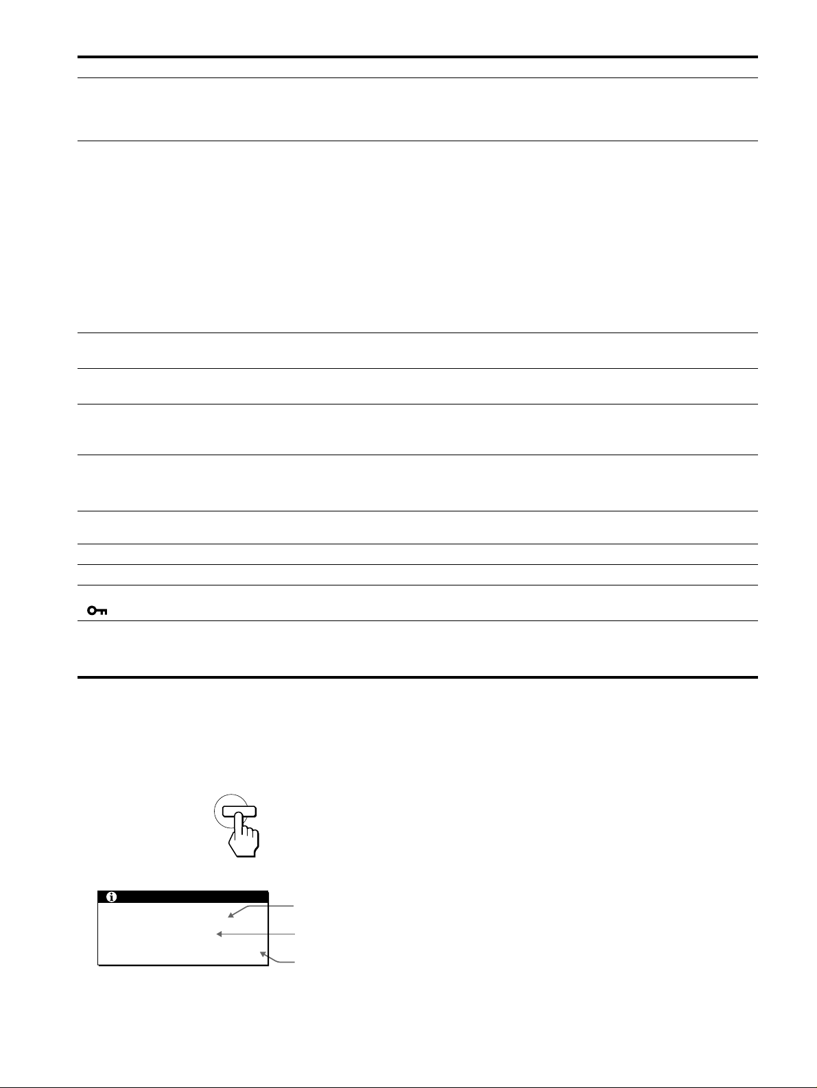
Displaying this monitor’s name, serial number,
and date of manufacture.
While the monitor is receiving a video signal, press and hold the
MENU button for more than 5 seconds to display this monitor’s
information box.
MENU
Example
INFORMATION
MODEL : SDM-N50PS
SER NO : 1234567
MANUFACTURED : 2000-15
Model name
Serial number
Week and year
of manufacture
If any problem persists, call your authorize d Sony d ealer and g ive
the following information:
• Model name: SDM-N50PS
• Serial number
• Name and specific ations of your computer an d graphics b oa r d.
20
Page 21
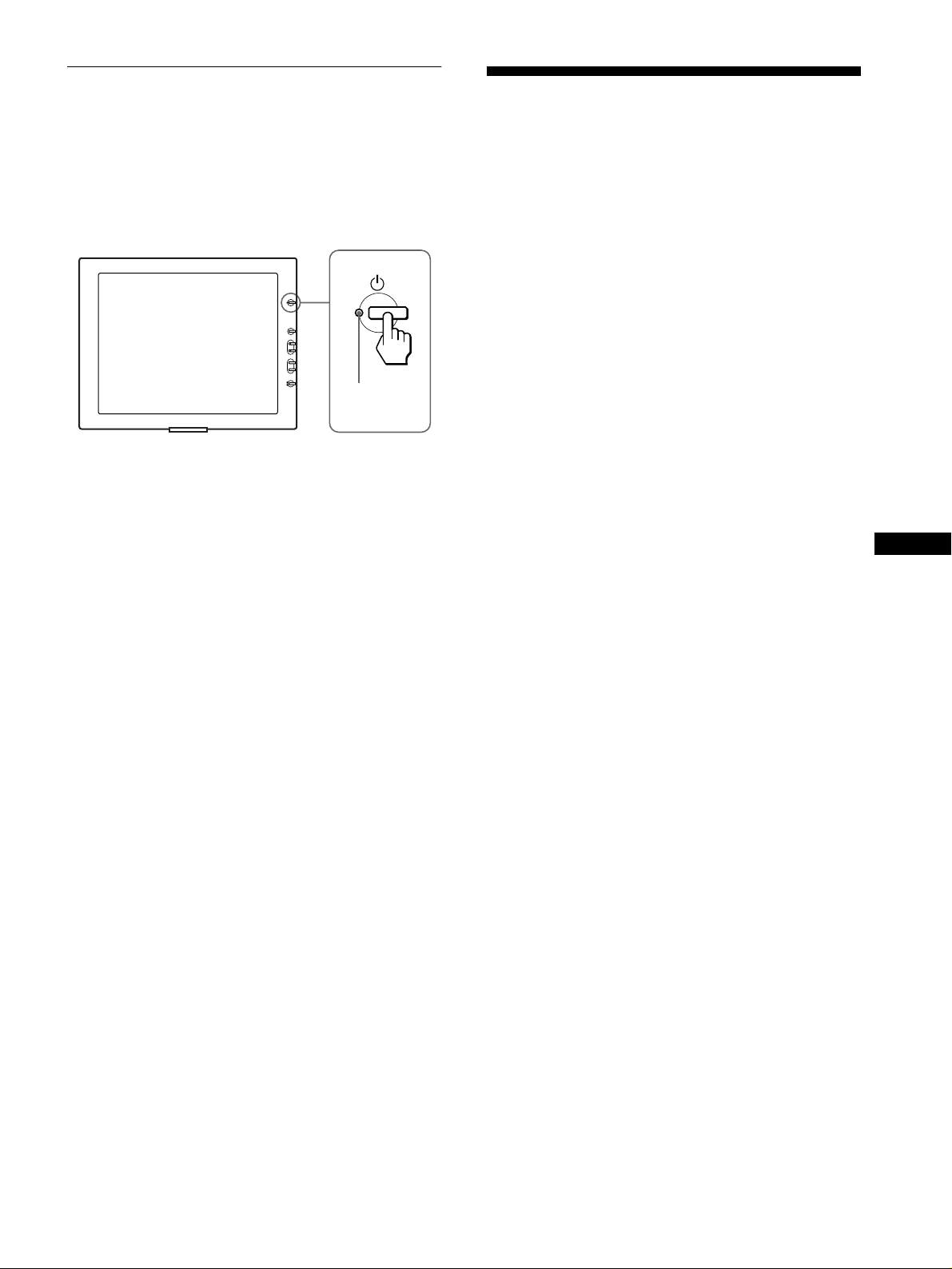
Self-diagnosis function
This monitor is equipped with a self-dia gnosis function. If the re is
a problem with your monitor or compute r(s), the screen will go
blank and the displa y’ s 1 (power) indicator will either light up
green or flash orange. If the 1 (power) indicator is lit in orange,
the computer is in power saving mode. Try pressing any key on
the keyboard or mo ving the mouse.
(power)
1
indicator
If the display’s 1 (power) indicator is green
1
Turn off the media engine’s AC power switch and
disconnect the video signal cables from the INPUT1
and INPUT2 connectors of the media engine.
2
Press the media engine’s AC power switch to turn
the monitor on.
If all four color bars appear (white, red, green, blue), the monitor
is working properly. Reconnect the video input cables and check
the condition of your computer(s).
If the color bars do not appear, there is a potential m onitor failure.
Inform your authorized Sony dealer of the monitor’s condition.
If the display’s 1 (power) indicator is flashing
orange
Press the 1 (power) switch twice to turn the monitor off
and then on.
If the 1 (power) indicator ligh ts up green, the mo nitor is working
properly.
If the 1 (power) indicator is still flashing, there is a potential
monitor failure. Count the number of seconds bet w een orange
flashes of the 1 (power) indicator and inform your authorized
Sony dealer of the mo nitor’s conditio n. Be sure to note the m odel
name and serial number of your monitor. Also note the make and
model of your computer and graphic board.
Specifications
LCD panel Panel type: a-Si TFT Active Matrix
Picture size: 15 inch (38 cm)
Input signal format RGB operating frequency*
Horizontal: 30 – 61 kHz
Vertical: 48 – 85 Hz (only XGA mode
at 75 Hz)
Resolution Horizontal: Max.1024 dots
Vertical: Max.768 lines
Input signal levels RGB video signal
0.700 Vp-p, 75 Ω, positive
SYNC signal
TTL level, 2 kΩ,
positive or negative
(Separate horizontal and vertical,
or composite sync )
0.3 Vp-p, 75Ω, negative
(Sync on green)
Headphones jack Stereo minijack
Accepts impedance of more than 16
AUDIO IN jack Stereo minijack
Accepts impedance of 47 k
Accepts level 0.5 Vrms
Power requireme nts 100 – 240 V, 50 – 60 Hz,
0.45 – 0.25 A
Power consumption Max. 28 W
°
Operating temperature 5 – 35
Dimensions (width/height/depth)
Mass Display (with stand):
Plug & Play DDC1/DDC2B/DDC2Bi
Accessories See page 8.
* Recommended horizontal and vertical timing co ndition
• Horizontal sync width duty should be more than 4.8% of total
horizontal time or 0.8 µs, wh iche ve r is larger .
• Horizontal blanking width should be more than 2.5 µsec.
• Vertical blanking width should be more than 450 µsec.
C
Display (without stand):
Approx. 356 × 280 × 26 mm
1
/16 × 11 1/
(14
Display (with stand, at maximum
angle: 40 °):
Approx. 356 × 225 × 203 mm
1
/16 × 8 7/
(14
Media engine (without stand):
Approx. 45 × 180 × 180 mm
3
/4 × 7 1/
(1
Media engine (with stand):
Approx. 94 × 185 × 180 mm
11
/16 × 7 1/
(3
Approx. 1.75 kg (3 lb 140 oz)
Media engine (with stand):
Approx. 0.85 kg (1 lb 14 oz)
8
8
7 1/8 inches)
×
4
Ω
6
1 1/16 inches)
×
8 inches)
×
7 1/8 inches)
×
Ω
GB
Design and specifications are subject to change without noti ce.
21
Page 22

Page 23

Table des matières
Précautions. . . . . . . . . . . . . . . . . . . . . . . . . . . . . . . . . . . . . . . . . . . . 4
Identification des composants et des commandes. . . . . . . . . . . . . . 6
Installation . . . . . . . . . . . . . . . . . . . . . . . . . . . . . . . . . . . . .8
• Macintosh est une marque commerciale
sous licence d’Apple Com puter, Inc.,
déposée aux Etats-Unis et dans d’autres
pays.
• Windows
marques commerc ia le s dép osées de
Microsoft Corporation aux Etats-Unis et
dans d’autres pays.
• IBM PC/AT et VGA sont des marques
commerciales déposées d’IBM
Corporation of the U.S.A.
• VESA et DDC
commerciales de Video Electronics
Standard Association.
•
E
déposée aux Etats-Unis.
•WinPortrait
marques commerc ia le s de Portrait
Displays, Inc.
• Tous les autres noms de produit
mentionnés dans le pré sent mode
d’emploi peuvent ê tre de s m a rques
commerciales ou des marqu es
commerciales déposées de leurs
entreprises respectives.
• De plus, les symboles “” et “” ne
sont pas systématiquement mentionnés
dans ce mode d’emploi.
et MS-DOS sont des
sont des marques
NERGY STAR est une marque
/MacPortrait sont des
Etape 1:
Etape 2:
Etape 3:
Etape 4:
Raccordez le moteur de médias à votre ordinateur. . . . . . 8
Raccordez l’écran et le moteur de médias . . . . . . . . . . . . 8
Raccordez le câble d’alimentation. . . . . . . . . . . . . . . . . . . 9
Mettez le moniteur et l’ordinateur sous tension . . . . . . . . . 9
Installation de l’écran en position verticale . . . . . . . . . . . . . . . . . . . 10
Utilisation des écouteurs. . . . . . . . . . . . . . . . . . . . . . . . . . . . . . . . . 10
Sélection de la langue d’affichage à l’écran (LANGUAGE) . . . . . . 11
Sélection du signal d’entrée . . . . . . . . . . . . . . . . . . . . . . . . . . . . . . 11
Personnalisation de votre moniteur. . . . . . . . . . . . . . . .12
Navigation dans les menus. . . . . . . . . . . . . . . . . . . . . . . . . . . . . . . 12
Réglage du contraste (CONTRASTE) . . . . . . . . . . . . . . . . . . . . . . 13
Réglage du niveau de noir de l’image (LUMINOSITE). . . . . . . . . . 13
Suppression du scintillement ou du flou (PHASE/HORLOGE). . . . 14
Réglage de la position de l’image
(CENTRAGE H/CENTRAGE V) . . . . . . . . . . . . . . . . . . . . . . . . . . . 14
Affichage d’un signal de faible résolution à la résolution en cours
(ZOOM). . . . . . . . . . . . . . . . . . . . . . . . . . . . . . . . . . . . . . . . . . . . . . 15
Réglage de la température des couleurs (COULEUR). . . . . . . . . . 15
Changement de la position du menu (POSITION MENU) . . . . . . . 15
Réinitialisation des réglages (RESTAUR) . . . . . . . . . . . . . . . . . . . 16
Réglages additionnels (Option) . . . . . . . . . . . . . . . . . . . . . . . . . . . 16
Spécifications techniques. . . . . . . . . . . . . . . . . . . . . . . .17
Fonction d’économie d’énergie. . . . . . . . . . . . . . . . . . . . . . . . . . . . 17
Fonction de réglage automatique de la qualité de l’image . . . . . . . 17
Dépannage . . . . . . . . . . . . . . . . . . . . . . . . . . . . . . . . . . . .18
Messages affichés . . . . . . . . . . . . . . . . . . . . . . . . . . . . . . . . . . . . . 18
Symptômes de défaillances et remèdes. . . . . . . . . . . . . . . . . . . . . 19
Fonction d’autodiagnostic. . . . . . . . . . . . . . . . . . . . . . . . . . . . . . . . 21
Spécifications. . . . . . . . . . . . . . . . . . . . . . . . . . . . . . . . . .21
Appendix. . . . . . . . . . . . . . . . . . . . . . . . . . . . . . . . . . . . . . . i
Preset mode timing table . . . . . . . . . . . . . . . . . . . . . . . . . . . . . . . . . .i
TCO’95 Eco-document . . . . . . . . . . . . . . . . . . . . . . . . . . . . . . . . . . .i
FR
3
Page 24
Précautions
Avertissement sur les branchements électriques
• Utilisez le câble d’alimentation fourni. Si v ous utilisez un câble
d’alimentation différent, assurez-vous qu’il est compatible
avec la tension secteur locale.
Pour les clients aux Etats-Unis
Si vous n’employez pas le câble approprié, ce moniteur ne sera
pas conforme aux normes FCC obliga to ir e s.
Pour les clients au Royaume-Uni
Si vous utilisez le moniteur au Royaume-Uni, veuillez utiliser
le câble d’alimentation adapté au Royaume-Uni.
Exemples de types de fiches
pour 100 à 120 V CA pour 200 à 240 V CA pour 240 V CA
uniquement
L’appareil doit être installé à proximité d ’une prise de cou rant
aisément accessible.
Installation
N’installez pas et ne laissez pas le moniteur:
• A des endroits exposé s à de s te m pé r a t u r es extrêmes, par
exemple à proximité d’un radiateur, d’un conduit de chauffage
ou le rayonnement di rect du sole il. L’ex position du moni teur à
des températures extrêmes, comme dans l’habitacle d’une
voiture parquée en plein soleil ou à proximité d’un conduit de
chauffage, risque d’entraîner des déformations du châssis ou
des dysfonctionnements.
• A des endroits soumis à des vibrations mécaniques ou à des
chocs.
• A proximité d’appa reils générant de puissants champs
magnétiques, comme un télévise ur ou d’autres appareils
électroménagers.
• A des endroit soumis à des quantités inhabituelle s de poussière,
de saletés ou de sable, par exem ple à cô té d’une f enêtre o uverte
ou d’une porte donnant sur l’extérieur. En cas d’installation
temporaire à l’extérieur, veillez à prendre les précautions
requises contre la poussière et les saletés en suspension dans
l’air. Faute de quoi des dommages irréparables risquent de se
produire.
Manipulation de l’écran LCD
• Ne lai ssez pas l’écran LCD face au soleil, car vous risquez
sinon de l’endommager. F aite s do nc a ttention si vous installez
le moniteur à côté d’ une fenêtre.
• N’appuyez pas sur et veillez à ne pas ér a fle r la s urf a c e de
l’écran LCD. Ne posez pas d’objets lourds sur l’écran LCD.
Vous risquez sinon d’altérer l’uniformi té de l’écran ou de
provoquer un dysfonctionnement de l’écran LCD.
• Lorsque le moniteur est employé dans un environnement froid,
il est possible qu’une image rémanente apparaisse sur l’écran.
Il ne s’agit pas d’un dysf onctionnement. L’éc ran recouvre sa
condition normale dè s que la température est revenue à un
niveau normal .
• Si une image fixe reste affichée pendant une longue durée, il se
peut qu’une image rémanente apparaisse pendant un certain
temps. Cette image rémanente finira par disparaître.
• Le panneau LCD s’échauffe en cours d’utilisation. Il ne s’agit
pas d’un dysfonctionnement.
A propos des points lumineux ou des points noirs
Il est possible que des points lumineux (rouges, bleus
ou verts) ou des points noirs apparaissent sur l’écran
LCD. Il ne s’agit pas d’un dysfonctionnement. L’écran
LCD est fabriqué en faisant app el à des technologies de
haute précision et plus de 99,99 % des éléments
d’image sont intacts. Il est cependant possible que
certains éléments d’image n’apparaissent pas ou que
certains éléments d’image apparaissent de manière
constante.
Remplacement du tube fluorescent
Un tube fluorescent de conception spéciale est installé dans ce
moniteur comme source lumineuse. Si l’écran s’assombrit, est
instable ou ne s’allume pas, remplacez le tube fluorescent. Pour le
remplacement du tube fluorescent, consultez votre revendeur
Sony.
Entretien
• Débranchez le câble d’alimentation de la prise secteur avant de
procéder au netto ya g e de vot r e mo niteur.
• Nettoyez l’écran LCD avec un chiffon doux. Si vous utilisez un
liquide de nettoyage pour le verre, n’utilisez pas de nettoyant
contenant une solution antistatique ou tout autre add itif
similaire, car vous risquez sinon de griffer le re vêtement de
l’écran LCD.
• Nettoyez le châssis, le panne au et les comm andes à l’ai de d’u n
chiffon doux légèrement imprégné d’une solution détergente
neutre. N’utilisez aucun type de tampon abrasif, de poudre à
récurer ou de solv ant tel que de l’alcool ou de la benzine.
• Ne frottez pas, ne touchez pas et ne tapotez pas la surface de
l’écran avec des objets point us ou abrasifs comme un stylo à
bille ou un tournevis. Ce type de contact risque de rayer le tube
image.
• Sachez qu’une détérioration des matériaux ou du revêtement de
l’écran LCD risque de se produire si le moniteur est exposé à
des solvants volatiles comme des insecticides ou en cas de
contact prolongé avec des objets en cao utchouc ou en vinyle.
Transport
• Pour transporter cet écran, débranchez tous les câbles, puis
saisissez fermement le moniteur de s deux mains pour le
transporter. Attention lors du transport du moniteur, si vous le
laissez tomber, vo us r is qu ez de l’endommager ou de vo us
blesser.
• Pour transporter ce moniteur en vue de réparations ou de son
expédition, utilisez le carton et les matériaux de
conditionnement originaux .
Elimination du moniteur
• Ne jetez pas ce moniteur avec les ordures
ménagères.
• Le tube fluorescent utilisé dans ce moniteur contien t
du mercure. L’élimination de ce moniteur doit être
effectuée conformément aux réglementations des
autorités locales compétentes en matière de propreté
publique.
4
Page 25
Pour installer l’écran horizontalement ou
verticalement
Cet écran peut être installé horizontalement ou verticalement à
l’aide du support fourni.
Ouvrez le support jusqu’à ce que vous entendiez un clic.
Placez l’écran sur le support, alignant la marque représentant la
position de l’écran sur l’écran.
Pour passer d’un affichage horizontal à un affichage vertical ou
vice versa, voir page 10.
Installat ion horizontale
Marque de positionnement du support
Pour régler l’angle
Cet écran peut être ajusté aux an gles illustrés ci-dessous avec le
support d’écran f ourni.
Pour ajuster l’angle, maint enez le support avant et poussez (ou
tirez) le pied arrière vers l’extérieur (ou vers l’intérieur), jusqu’à
ce que l’écran soit dans la position vo ulue.
Pour installer l’écran sur son support, procédez doucement.
40°
20°
Remarque
Ne dépassez pas les angles illustrés ci-de ssus, sinon l’écr an risquerait de
tomber, ce qui pourrait l’endommager.
Installat ion verticale
Marque de positionnement du support
Pour refermer le support de l’écran
Tout en faisant glisser la butée d’arrêt vers le haut, fermez le
support de l’écran.
Pour utiliser l’écran confortablement
Cet écran est conçu de manière à ce que vous puissiez le régler
suivant un angle de visualisation confortable. Ajustez l’angle de
visualisation d e votre é cran en fo nction de la hauteu r du burea u et
de votre chaise et de manière à ce que l’écran ne vous réfléchisse
pas la lumière dans les yeux.
FR
Butée
5
Page 26
Identification des composants et
des commandes
Pour plus de détails, reportez-vous aux pages entre parenthèses.
Ecran LCD
Avant
MENU
INPUT
1
2
OK
1111 Commutateur et indicateur 1 (alimentation)
(pages 9, 17, 21)
Ce commutateur sert à la mise sous et hors tension de l’écran.
L’indicateur s’allume en vert lorsque le moniteur est sous
tension. L’indicateur s’allume en orange lorsque le monite ur
est en mode d’écon omie d’énergie.
2 Touche MENU (menu) (page 13)
Cette touche active l’affich age du menu principal.
3 Touche 6 (contraste) (page 13)
Cette touche active l’affichage du menu CONTRASTE.
4 Touche 8 (luminosité) (page 1 3)
Cette touche active l’affichage du menu LUMINOSITE.
5555 Touches 2 (volume) +/– et M(+)/m(–) (pages 10, 13)
Ces touches activent l’affichage du menu VOLUME et
servent de touches fléchées M(+)/m(–) pour séle c tio nner des
paramètres de menu et eff ectuer des réglages.
6666 Touche INPUT (entrée) et OK, et indicateur
(pages 11, 13)
Cette touche sélectionne le signal d’entrée vidéo INPUT 1 ou
INPUT 2. Le signal d’entrée et l’in dicateur d’entrée
correspondant changent chaque fois que vous appuyez sur
cette touc he.
Cette touche sert également de touche OK lorsque le menu est
affiché à l’écran.
Arrière/Côté
7777 SYSTEM CONNECTOR (CONNECTEUR DU
SYSTEME) (page 8)
Ce connecteur entre les signaux du moteur de médias lorsque
l’écran et le moteur de médias sont raccordés au moyen de
câble de connexion s ystème.
8888 Prise pour casque d’écoute (page 10)
Cette prise sort les signaux audio vers un casque d’écoute.
9999 Compartiment câble
Ce compartiment est utilisé pour ranger le câble de connex ion
du système.
0000 Trou du verrou de sécurité ( )
Le trou du verrou de sé curité devra être uti lisé avec le système
Micro Saver Secur ity de Kensignton.
Micro Saver Security System est une marque commerciale de
Kensington.
qa
qa Support d’écran
qaqa
Ce support est utilisé pour installer l’écran.
6
Page 27
Moteur de médias
SYSTEM CONNECTER
(
)
TO DISPLAY
qg
qg Connecteur 2 d’entrée HD15 (RVB) (INPUT2)
qgqg
(page 8)
Ce connecteur entr e les signaux vidéo RVB (0,700 Vp-p,
positifs) et les signaux SYNC. L’assignation des broches est
la même que pour le connecteur qf.
INPUT 1
AUDIO IN
INPUT 2
qs
qs Prise AUDIO IN (page 10)
qsqs
Cette prise entre les signaux audio lorsqu’il est raccordé à la
prise de sortie audio de l’ordinateur ou d’un autre appare il
audio.
qd
qd SYSTEM CONNECTOR (CONNECTEUR DU
qdqd
SYSTEME) (TO DISPLAY) (page 8)
Ce connecteur sort les signaux du moteur de médias lorsque
l’écran et le moteur de médias sont raccordés au moyen de
câble de connexion système.
qf
qf Connecteur 1 d’entrée HD15 (RVB) (INPUT1)
qfqf
(page 8)
Ce connecteur entre les signaux vidéo RVB (0,700 Vp-p,
positifs) et les signaux SYNC.
qh
qh Connecteur AC IN (page 9)
qhqh
Ce connecteur assure l’alimentation secteur du moniteur.
qj
qj Commutateur d’alimentation secteur (page 9)
qjqj
Ce commutateur a pour e f fet de mettr e le mo te ur de mé dias
sous tension et hors ten sion. Lorsque l’alimentati on électrique
est coupée ou rétablie, l’affichage s’allume ou s’éteint
automatiquement.
qk
qk Indicateur d’alimentation secteur (page 17)
qkqk
Cet indicateur s’allume en vert lorsque le moteur de médias
est sous tension. Cet indicateur s’allume en rouge lorsque
l’écran est hors tension et que le moteur de médias est sous
tension. L’indicateur s’allume en orange lorsque le moniteur
se trouve en mode d’économ ie d’énergie.
ql
ql Support du moteur de médias
qlql
Ce support sert à installer le moteur de médias vertic aleme nt .
Attention
Veillez à installer le moteur de m édias verticaleme n t co m me illustré à
gauche. L’installation du moteur de médias en position horizontale risque
de bloquer les orifices de ventilation et de provoquer un
dysfonctionnement.
FR
5 4 3 2
1
678910
1112131415
Broche n° Signal
1 Rouge
2Vert
(Synchronisation sur le vert)
3Bleu
4 ID (masse)
5 Masse DDC*
6 Masse du rouge
7 Masse du vert
8 Masse du bleu
9 DDC + 5V*
10 Masse
11 ID (masse)
12 Données bidirectionnelles (SDA)*
13 Synchronisation H
14 Synchronisation V
15 Horloge de données (SCL)*
* DDC (Display Data Channel) est une norme de VESA.
7
Page 28
Installation
Utilisez l’adaptateur Macintosh fourni.
vers le connecteur
INPUT1 ou INPUT2
Adaptateur Macintosh
(fourni)
*
Câble de signal vidéo
HD15 (RVB) (fourni)
vers la sortie vidéo
Ordinateur Macintosh
ou compatible
vers le SYSTEM
CONNECTOR
(connecteur
système) du moteur
de médias
Câble de connexion
système (2 m) (fourni)
vers le SYSTEM
CONNECTOR
(connecteur
système) de
l’écran
Avant d’utiliser votre moniteur, vérifiez si les accessoires
suivants se trouvent bien dans le carton d’emballage:
• Ecran LCD
• Moteur de médias
• Support d’écran
• Support du moteur de médias
• Câble d’alimentation
• Câble de connexion système (2 m)
(type de câble applicable : DP-2)
• Câble de signal vidéo HD15 (RVB)
• Câble audio (minifiche stéréo)
• Adaptateur Macintosh
• Windows Monitor Information Disk/Utility Disk
• Macintosh Utility Disk
• Logiciel à utiliser pour installer l’écran verticalement
(WinPortrait/MacPortrait)
• Carte de garantie
• Remarques pour les utilisateurs Macintosh
• Ce mode d’emploi
Etape 1:Raccordez le moteur de
médias à votre ordinateur
Raccordement à un ordinateur Macintosh
x
ou compatible
Mettez le moteur de médias et l’ordinateur hors tension avant de
procéder aux connexions.
Remarque
Ne touchez pas les broches du connecteur du câble de signal vidéo, car
vous risquez sinon de plier les bro ch es.
Raccordement à un ordinateur IBM PC/AT
x
ou compatible
Ordinateur IBM PC/AT
Ordinateur IBM PC/AT
ou compatible
ou compatible
vers la sortie vidéo
vers le connecteur
INPUT1 ou INPUT2
Câble de signal vidéo
HD15 (RVB) (fourni)
* Pour plus de détails, reportez-vous aux “Remarques pour les
utilisateurs Macin tosh ” fournies.
Etape 2:Raccordez l’écran et le
moteur de médias
Mettez l’écran et le moteur de médias hors tension avant de
procéder aux connexions.
Attention
Veillez à installer le moteur de médias verticalement comme illustré
ci-dessus. L’installation du moteur de médias en position horizontale
risque de bloquer les orific es de ven ti la tion et de provoquer un
dysfonctionnement.
8
Remarque
Branchez le câble en le saisiss ant par la fiche.
Page 29
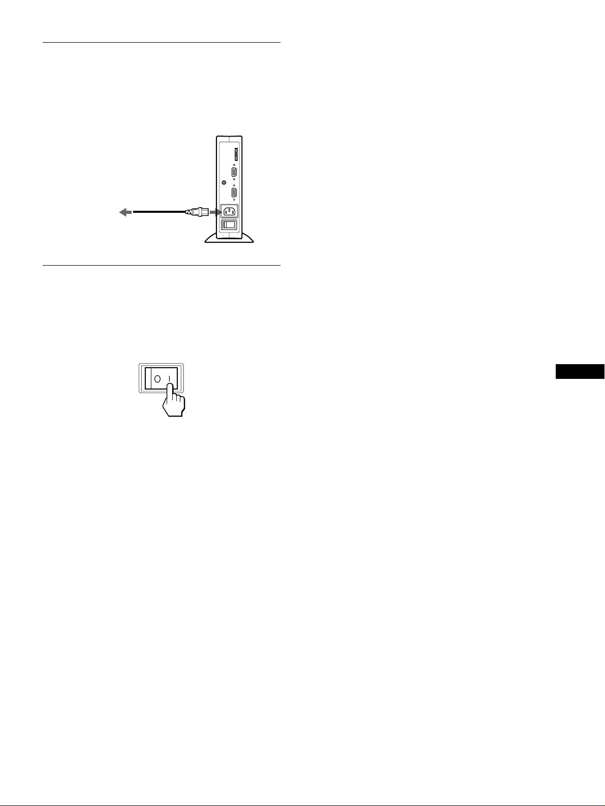
Etape 3:Raccordez le câble
d’alimentation
L’écran, le moteur de médias et l’ordinateur étant hors tension,
connectez d’abord le câble d’alimentation au moteur de médias,
puis connectez celui-ci à une pris e électrique.
vers AC IN
vers une prise
secteur
Câble d’alimentation
(fourni)
Etape 4:Mettez le moniteur et
l’ordinateur sous tension
1
Mettez le moteur de médias sous tension.
L’écran s’allume automatiquement. Les indicateurs de l’écran
et du moteur de médias s’allum ent en vert.
2
Mettez l’ordinateur sous tension.
L’installation de votre moniteur est à présent terminée. Si
nécessaire, utilisez les commandes du moniteur pour régler
l’image.
Si aucune image n’apparaît à l’écran
• Véri f iez que le moniteur est correctement raccordé à
l’ordinateur.
• Vérifiez que le moteur de médias est sous tension.
• Si le message PAS ENTREE VIDEO apparaît, l’ordinateur est
en mode d’économie d’énergie. Essayez d’appuyer sur une
touche ou de déplacer la souri s.
• Si le messag e CABLE DECONNECT apparaît, essayez de
modifier le signal d’entrée (page 11) et véri fi ez que le câble
d’entrée vidéo est branché correctement.
• Si l’indication HORS PLAGE DE BALAYAGE apparaît à
l’écran, reconnectez l’ancien moniteur. Réglez ensuite la carte
graphique de l’ordinateur de façon à ce que la fréquence
horizontale soit comprise en tre 30 – 61 kHz, et la fréquence
verticale entre 48 – 85 Hz (uniquement en mode XGA à 75 Hz).
Pour des informations plus détaillées sur les messages à l’écran,
voir “Symptômes de défaillances et remèdes” à la page19.
Pour les utilisateurs de Windows 95/98
Pour optimiser votre moniteur, installez sur vot re ordinateur le fichier
d’information sur le no uve au modèle à partir de la disq ue tt e Windows
Monitor Information Disk.
Ce moniteur répond à la norme Plug & Play “VESA DDC”. Si votre carte
PC/graphique répond à DDC, sélectionnez “Plug & Play Monitor (VESA
DDC)” ou la désignation de ce moniteur comme type de moniteur dans le
“Panneau de confi guration” de Windows 95/98. Si votre PC/carte
graphique présente des difficultés à communi quer avec ce moniteu r,
chargez le Windows Monitor Information Disk et sélectionnez le nom de
modèle correspondant à ce moniteur comme type de moniteur.
FR
Pour les utilisateurs de Windows NT4.0
La configuration du mon iteur sous Windows NT4.0 est différente de
Windows 95/98 et ne nécessite pas la sél ec ti on du type de moniteur.
Reportez-vous au mode d’e m pl oi de Windows NT 4.0 pour obtenir plus
de détails sur le réglage de la résolution, du taux de rafraîchissement
(fréquence verti ca le) et du nombre de coul eurs.
Réglage de la résolution du moniteur et du nombre de
couleurs
Réglez la résolution du moniteur et le nombre de couleurs en vous référant
au mode d’emploi de votre ordinateur. Le nombre de couleurs peut varier
en fonction de votre ordinateur ou de votre carte graphique. Réglez la
palette de couleurs et le no mbre de couleurs comm e sui t:
• High Color (16 bits) t 65.536 couleurs
• True Color (24 bits) t environ 16,77 millions de couleurs
En mode True Colo r (24 bits), la vitesse peut être plus lente.
9
Page 30
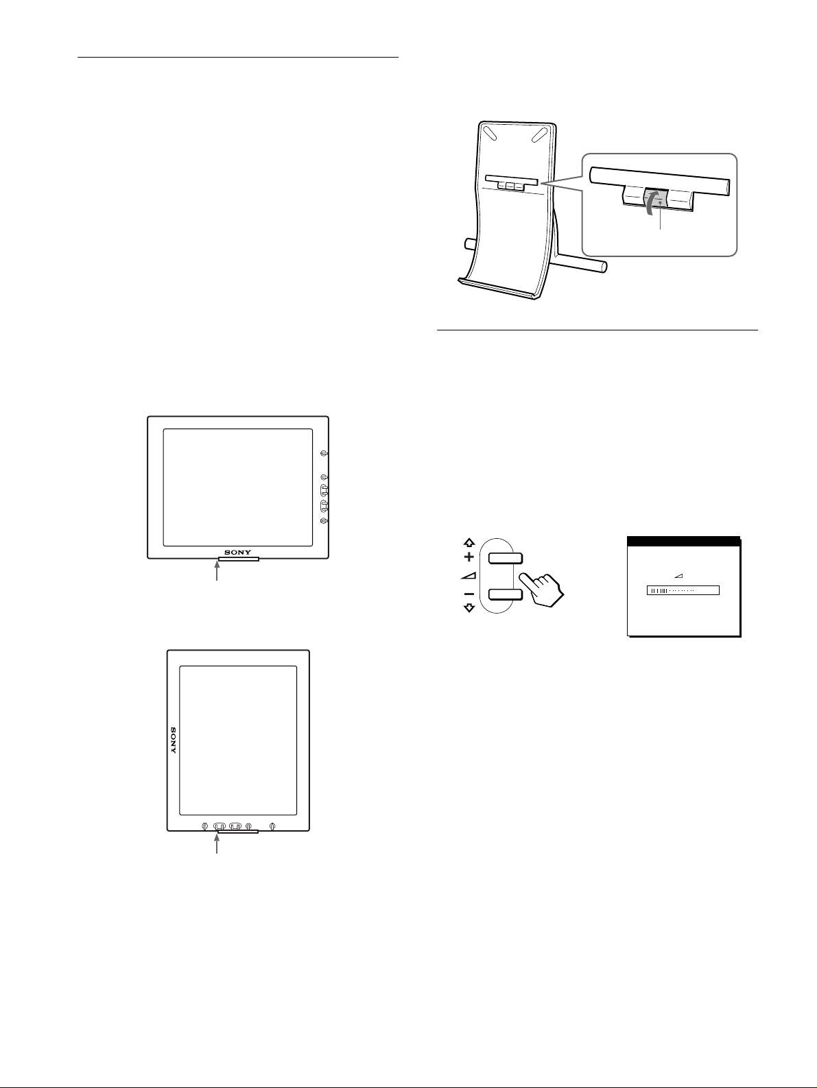
Installation de l’écran en position
Butée
,
verticale
Cet écran peut être installé horizontalement ou verticalement à
l’aide du support fourni.
Pour changer la positon de visualisation
horizontale ou verticale
Installez dans un premier temps le logiciel WinPortrait (pour
Windows 95/98 et NT4.0) ou MacPortrait (pour Macintosh). Pour
passer d’une vue à une autre, appuyez sur Maj + Ctrl + R sur votre
clavier. Pour plus d’informations à ce sujet, reportez-vous au
manuel d’utilisation du logiciel.
Pour installer l’écran horizontalement ou
verticalement
Ouvrez le support jusqu’à ce que vous entendiez un clic.
Placez l’écran sur le support, alignant la marque représentant la
position de l’écran sur l’écran.
Installat ion horizontale
Pour refermer le support de l’écran
Tout en faisant glisser la butée d’arrêt vers le haut, fermez le
support de l’écran.
Utilisation des écouteurs
Vous pouvez écouter les signaux audio d e votre ordinateur ou
d’un autre appareil audio à l’aide d’un casque d’écoute.
Raccordez la prise AUDIO IN à la prise de sortie audio de votre
ordinateur ou d’ un autre appareil audio à l’aide du câble audio
fourni.
Marque de positionnement du support
Installat ion verticale
Marque de positionnement du support
Réglage du volume
1
Appuyez sur les touches 2 +/–.
Le menu VOLUME apparaît sur l’écran.
VOLUME
40
2
Appuyez sur les touches 2 +/– pour régler le
volume.
Le menu disparaît automatiquement au bout d’environ
3 secondes.
Remarques
• Vous ne pouvez pas rég le r le volume lorsque le menu principal est
affiché à l’écra n.
• Lorsque votre moniteur est en mode d’économie d’énergie, aucun son
n’est émis par le casque d’écoute.
10
Page 31

Sélection de la langue d’affichage
Sélection du signal d’entrée
à l’écran (LANGUAGE)
Les menus peuvent être affichés en anglais, allemand, français,
italien et japonais. La langue par défaut est l’anglais.
1
Appuyez sur la touche MENU.
PHAS E
MENU
,
2
Appuyez sur les touches M(+)/m(–) pour
16
EX I T
sélectionner m.
ACCENT GRAVES
OUI
NON
,
EX I T
Vous pouvez raccorde r deux ordinateurs à ce moniteur via les
connecteurs INPUT 1 et INPUT 2. Pou r sé lectionner l’un des
deux ordinateurs, utilisez la touche INPUT.
Appuyez sur la touche INPUT.
Le signal d’entrée et l’indi cateur d’entrée correspondant,
“1” (INPUT 1) ou “2” (INPUT 2), changent chaque fois que vous
appuyez sur cette touche.
INPUT
1
2
OK
Remarques
• Vous ne pouvez pas sél ec ti onner le signal d’entrée lo rsque le menu
principal est affich é à l’écran.
• Si aucun signal n’est e nt ré par le connecteur sélecti onné, le message
PAS ENTREE VIDEO ou CABLE DECONNECT apparaît à l’écran.
Au bout de quelques secondes, le moniteur passe en mode d’économie
d’énergie. Si cela se produit, sélectionnez l’autre connecteur à l’aide de
la touche INPUT.
FR
3
Appuyez sur les touches M(+)/m(–) pour
sélectionner (LANGUAGE) puis appuyez sur OK.
LANGUAGE
INPUT
1
2
,,
4
Appuyez sur les touches M(+)/m(–) pour
OK
ENGL I SH
DEUTSCH
FRANÇAI S
ESPAÑOL
ITALIANO
EX I T
sélectionner une langue.
• ENGLISH : Anglais
• DEUTSCH : Allemand
• FRANÇAIS
• ESPAÑOL : Espagnol
• ITALIANO : Italien
• : Japonais
Pour fermer le menu
Appuyez une fois sur la touche ME NU pour revenir à un affichage
normal. Si vous n’appuyez sur aucune touche, le menu est
automatiquem en t fermé après 30 seco ndes environ.
11
Page 32

Personnalisation de votre
moniteur
Avant de procéder aux réglages…
Raccordez le moniteur et l’ordinateur et mettez-les sous
tension.
Pour obtenir les meilleurs résultats, attendez au moins
30 minutes avant d’effectuer les réglages.
Vous pouvez effectuer de nombreux réglages de votre moniteur à
l’aide des menus à l’écran.
Navigation dans les menus
Appuyez sur la touche MENU pour afficher le menu principal sur
votre écran. Voir page 13 pour plus de détails sur l’utilisation de
la touche MENU.
PHASE
MENU
4444 CENTRAGE V (page 14)
Sélectionnez le menu
CENTRAGE V pour ajuster
le centrage vertical de
l’image.
5555 ZOOM (page 15)
Sélectionnez le menu ZOOM
pour ajuster la taille de
l’image en fonction du
rapport d’aspect ou de la
résolution du signal d’entré e.
6666 COULEUR (page 15)
Sélectionnez le menu
COULEUR pour ajuster la
tonalité des couleurs de
l’affichage.
CENTREGE V
ZOOM
OU I
NON
COUL EUR
9300K
0K
650
5000K
UTI L I SATEUR
RLEGLER
25
EX I T
EX I T
EX I T
,
Utilisez les touches M(+)/m(–) et OK pour sélectionner l’un des
menus suivants. Reportez-vous à la page 13 pour plus de détails
sur l’utilisation des touches M(+)/m(–) et OK.
1 PHASE (page 14)
Sélectionnez le menu
PHASE pour ajus ter la ph ase
lorsque les caractères ou les
images apparaissent floues
sur toute la surface de
l’écran. Ajustez la phase
après avoir réglé l’horloge.
2222 HORLOGE (page 14)
Sélectionnez le menu
HORLOGE pour ajuster
l’horloge lorsque les
caractères ou les images
manquent de clart é dans
certaines parties de l’écran.
PHAS E
16
EX I T
HORLOGE
0
EX I T
7777 POSITION MENU
(page 15)
Sélectionnez le menu
POSITION MENU pour
changer la position
d’affichage du menu sur
l’écran.
8888 RESTAUR (page 16)
Sélectionnez le menu
RESTAUR pour restaurer les
réglages.
9999 Option (page 16)
Sélectionnez le menu
m (Option) pour ajuster les
options du moniteur. Les
options incluent:
• ACCENT GRAVES
• RETROECLAIRAGE
• MODE ECO
• LANGUAGE
• VERROU REGLAGES
POS UTIION ENM
EX I T
REST AUR
RECRAN
RESTAU
AUR TOTAL
REST
EX I T
ACCENT GRAVES
OUI
NON
EX I T
3333 CENTRAGE H (page 14)
Sélectionnez le menu
CENTRAGE H pour ajuster
le centrage horizontal de
l’image.
12
CENTREGE H
50
EX I T
Page 33

Utilisation des touches MENU, M(+)/m(–) et
48.4kHz/ 60Hz
CONTRASTE
70
48.4kHz/ 60Hz
LSITEUM I NO
50
x
OK
1
Affichez le menu principal.
Appuyez sur la touche MENU pour afficher le menu principal
sur votre écran.
Réglage du contraste (CONTRASTE)
Le réglage du contraste se fait via un menu CONTRASTE distinct
du menu principa l (page 12). Ce réglag e es t en r e gistré dans la
mémoire pour le signal du connecteur d’entrée actuellement
sélectionné.
MENU
2
Sélectionnez le menu que vous voulez régler.
Appuyez sur les touches M(+)/m(–) pour afficher le menu de
votre choix. Appuyez sur la touche OK pour sélectionner un
paramètre.
INPUT
,
3
Ajustez le menu.
Appuyez sur les touches M(+)/m(–) pour effectuer le réglage.
Appuyez sur la touche OK pour revenir au menu précédent.
,
1
2
OK
INPUT
1
2
OK
1
Appuyez sur la touche 6 (contraste).
Le menu CONTRASTE apparaît à l’écran.
Fréquence horizontale du
signal d’entrée en cours
Affichage du signal d’entrée en cours
Les fréquences horizontale et verticale du signal d’entrée en cours sont
affichées dans les menus CONTRASTE et LUMINOSITE.
2
Appuyez sur les touches M(+)/m(–) pour régler le
contraste.
Le menu disparaît aut omatiquement au bout d’environ
3 secondes.
Fréquence verticale du
signal d’entrée en cours
Réglage du niveau de noir de
l’image (LUMINOSITE)
Le réglage de la luminosité s’effectue via un menu
LUMINOSITE distinct du menu principal (page 12). Ce réglage
est enregistré dans la mémoire pour le signal du connecteur
d’entrée actuellement sélectionné.
FR
4
Refermez le menu.
Appuyez une fois sur la touche MENU pour revenir en mode
de visualisation normale. Si vous n’actionnez aucune touche,
le menu se referme au tomatiquement au bout d’environ
30 secondes.
MENU
Réinitialisation des réglages
x
Vous pouvez réinitialiser les réglages à l’aide du menu
RESTAUR. Voir page 16 pour plus de détails sur la
réinitialisation des réglages.
1
Appuyez sur la touche 8 (luminosité).
Le menu LUMINOSITE apparaît à l’écran.
Fréquence horizontale du
signal d’entrée en cours
2
Appuyez sur les touches M(+)/m(–) pour régler la
luminosité.
Le menu disparaît aut omatiquement au bout d’environ
3 secondes.
Fréquence verticale du
signal d’entrée en cours
Si l’écran est trop lumineux
Ajustez le rétroéclairage. Pour des informations plus détaillées
sur le réglage du rétroéclairage, voir “Réglage du rétroéclairage”
à la page 16.
Remarque
Vous ne pouvez pas régler le contraste ni la luminosité lorsque le menu
principal est affi ché à l’écran.
13
Page 34

Suppression du scintillement ou
du flou (PHASE/HORLOGE)
Lorsque le moniteur reçoit un signal d’entrée, la fonction de
qualité automatique de l’image de ce moniteur est activée. Cette
fonction ajuste automatiquement la phase, la profondeur et la
position de l’image pour qu’une image précise soit affichée à
l’écran. Pour plus d’informations sur cette fonction, reportezvous à “Fonction d e réglage autom atique de la qu alité de l’image ”
à la page 17.
Pour certain e s entrées, il est possible que ce t te fonction n ’ajuste
pas totalement la phase, la profondeur et la position de l’image.
Dans ce cas, vous pouvez effectuer ces ajustements manuellement
en appliquant les instructions suivantes. Si vous effectuez ces
ajustements manuelleme nt, ils sont mémorisés et
automatiquement rappelés chaque fois que le moniteur reçoit les
mêmes signaux d’entrée.
Il se peut que ces réglages doivent être répétés si vous changez le
signal d’entrée après avoir reconnecté votre ordinateur.
1
Réglez la résolution sur 1024
2
Chargez la disquette d’utilitaire.
Utilisez la disquette appropriée en fonction de votre
ordinateur.
Pour Windows 95/98
Windows Monitor Information Disk/Utility Disk
Pour Macintosh
Macintosh Utility Disk
3
Démarrez la disquette d’utilitaire et affichez la mire
de test.
Pour Windows 95/98
Cliquez sur [Utility Disk]
Pour Macintosh
Cliquez sur [Utility Disk]
4
Appuyez sur la touche MENU.
Le menu principal apparaît à l’écran.
5
Appuyez sur les touches M(+)/m(–) pour
sélectionner (HORLOGE ) et appuyez ensuite sur
la touche OK.
Le menu HORLOGE apparaît à l’écran.
6
Appuyez sur les touches M(+)/m(–) pour régler la
profondeur.
Ajustez la valeur jusqu’à ce que les rayures verticales aient
disparu.
t
t
768 sur l’ordinateur.
××××
[Windows]/[Utility.exe].
[SONY-Utility].
8
Appuyez sur les touches M(+)/m(–) pour
sélectionner (PHASE) et appuyez ensuite sur la
touche OK.
Le menu PHASE apparaît à l’écran.
9
Appuyez sur les touches M(+)/m(–) pour régler la
phase.
Ajustez la valeur de façon à ce que les rayures horizontales
aient été réduites au minim um.
10
Cliquez sur [END] à l’écran pour désactiver la mire
de test.
Pour réinitialiser le réglage automatique de la qualité d’image
Sélectionnez RESTAUR ECRAN et activez-le dans le menu RESTAUR.
Reportez-vous page 16 pour plus d’informations sur l’utilisation du menu
RESTAUR.
Réglage de la position de l’image
(CENTRAGE H/CENTRAGE V)
Si l’image n’est pas centrée à l’écran, ajustez le centrage de
l’image en procédant comme suit.
Il se peut que ces réglages doivent être répétés si vous changez le
signal d’entrée ap rès avoir reconnecté votre ordinateur.
1
Démarrez la disquette d’utilitaire et affichez la mire
de test.
Répétez les étapes 2 et 3 de la procédure “Suppression du
scintillement ou du flou (PHASE/HORLOGE).”
2
Appuyez sur la touche MENU.
Le menu principal apparaît à l’écran.
3
Appuyez sur les touches M(+)/m(–) pour
sélectionner (CENTRAGE H) ou (CENTRAGE
V) et appuyez ensuite sur la touche OK.
Le menu CENTRAGE H ou CENTRAGE V apparaît à
l’écran.
4
Déplacez l’image vers le haut, le bas, la gauche ou
la droite jusqu’à ce que le cadre matérialisant le
contour de la mire de test ait disparu.
Appuyez sur les touches M(+)/m(–) pour ajuster le
centrage de l’image à l’aide du menu CENTRAGE H
pour le réglage horizontal ou du menu CENTRAGE
V pour le réglage vertical.
7
Appuyez sur la touche OK.
Le menu principal apparaît à l’écran.
Si vous observez des rayures horizontales sur toute la surface
de l’écran, ajustez la phase à l’étape suivante.
14
5
Cliquez sur [END] à l’écran pour désactiver la mire
de test.
Page 35

Affichage d’un signal de faible
R168
V170
B175
EX I T
REGL UTILISAT
résolution à la résolution en cours
(ZOOM)
Ce moniteur est réglé par défaut pour afficher des images sur toute
la surface de l’écran, quel que soit le mode ou la résolution de
l’image. Vous pouvez égalem ent visualiser l’image à sa
résolution réelle.
1
Appuyez sur la touche MENU.
Le menu principal apparaî t à l’ écran.
2
Appuyez sur les touches M(+)/m(–) pour
sélectionner (ZOOM) et appuyez ensuite sur la
touche OK.
Le menu ZOOM apparaît à l’écran.
3
Appuyez sur la touche m(–) pour sélectionner NON.
Le signal d’entrée est affiché sur l’écran à sa résolution réelle.
4
Si nécessaire, ajustez finement la température des
couleurs.
Appuyez d’abord sur les touches M(+)/m(–) pour sélectionner
REGLER et appuyez ensuite sur la touche OK. Appuyez
ensuite sur les touches M(+)/m(–) pour sélectionner R (rouge)
ou B (bleu) et puis sur la touche OK, puis appuyez sur les
touches M(+)/m(–) pour ajuster la température des co uleurs.
Etant donné que ce réglage change la température des
couleurs en augmentant ou en diminuant les composantes R et
B par rapport à V (vert), la composante V est fixe.
Si vous ajustez finement la température des couleurs, le
nouveau réglage des couleurs est enregist ré dans la mémoire
comme REGL UTILISAT et est automatiquement rappelé
chaque fois que UTILISATEUR est sélectionné.
Le réglage REGL UTILISAT est commun aux deux signaux
d’entrée. Si vous changez le réglage utilisateur pour un signal
d’entrée, le réglage de l’autre signal d’entrée est changé lui
aussi.
Pour afficher l’image sur toute la surface de l’écran
Sélectionnez OU I à l’étape 3.
Réglage de la température des
couleurs (COULEUR)
Les réglages COULEUR vous permettent d’ ajuster la température
des couleurs de l’image en changeant le niveau de couleur des
zones de couleur blanche. Les couleurs apparaissent rougeâtres si
la température est basse et bleuât res si la température est élevée.
9300K convient généralement au traitement de texte et autres
applications orientées vers le texte, et 6500K aux images vidéo.
Vous pouvez régler la température des couleurs sur 5000K,
6500K, 9300K ou personnaliser votre réglage.
1
Appuyez sur la touche MENU.
Le menu principal apparaî t à l’ écran.
2
Appuyez sur les touches M(+)/m(–) pour
sélectionner (COULEUR) et appuyez ensuite sur
la touche OK.
Le menu COULEUR apparaît à l’écran.
3
Appuyez sur les touches M(+)/m(–) pour
sélectionner la température des couleurs de votre
choix.
Les températures des couleurs présélectionnées sont 5000 K,
6500K et 9300K. Etant donné que le réglage par défaut est de
9300K, les blancs virent d’une nuance bleuâtre à une nuance
rougeâtre lorsque la température est abaissée à 6500K et
5000K.
Vous pouvez régler des températures de couleur séparées
pour chaque signal d’en trée vidéo.
Changement de la position du
menu (POSITION MENU)
Vous pouvez changer la position du menu s’il obstrue une image
à l’écran.
1
Appuyez sur la touche MENU.
Le menu principal apparaît à l’écran.
2
Appuyez sur les touches M(+)/m(–) pour
sélectionner (POSITION MENU) et appuyez
ensuite sur la touche OK.
Le menu POSITION MENU apparaît à l’écra n.
3
Appuyez sur les touches M(+)/m(–) pour afficher la
position de votre choix.
Vous avez le choix entre trois po sitions pour le ha ut et pour le
bas de l’écran, et une position pour le centre de l’écran.
15
FR
Page 36

Réinitialisation des réglages
Réglages additionnels (Option)
(RESTAUR)
Vous pouvez réinitialiser les réglages.
1
Appuyez sur la touche MENU.
Le menu principal apparaît à l’écran.
2
Appuyez sur les touches M(+)/m(–) pour
sélectionner 0 (RESTAUR) et appuyez ensuite sur
la touche OK.
Le menu RESTAUR apparaît à l’écran.
Vous pouvez réinitialiser les réglages de l’une des deux
manières su i vantes:
Réinitialisation des données de réglage les mieux
appropriées en fonction du signal d’entrée en
cours
Appuyez sur les touches M(+)/m(–) pour sélectionner
RESTAUR ECRAN et appuyez ensuite sur la touche OK.
La fonction d’ajustem ent autom atique de la qu alité d e l’i mage de
ce moniteur aju st e a u tom a tiq ue m e nt l a ph as e , la profondeur e t la
position de l’image sur les valeurs les plus adéquates. Si cette
fonction est activée, la phase est automatiquement ajustée à
chaque fois que le moniteur reçoit le même signal d’entrée.
Le menu RESTAUR r evien t autom atiquem ent au menu prin cipal
après la réinitialisation des réglages.
Réinitialisation de toutes les données de réglage
pour tous les signaux d’entrée
Appuyez sur les touches M(+)/m(–) pour sélectionner
RESTAUR TOTAL et appuyez ensuite sur la touche OK.
Le menu RESTAUR r evien t autom atiquem ent au menu prin cipal
après que les données de réglages ont été restaurées.
Pour annuler la réinitialisation
Appuyez sur les touches M(+)/m(–) pour sélectionner
et appuyez ensuite sur la touche OK.
Le menu RESTAUR revient au menu principal sans réinitialiser
les données de réglage.
Vous pouvez ajuster les options suivantes:
• ACCENT GRAVES
• RETROECLAIRAGE
• MODE ECO
• LANGUAGE
• VERROU REGLAGES
1
Appuyez sur la touche MENU.
Le menu principal apparaît à l’écran.
2
Appuyez sur les touches M(+)/m(–) pour
sélectionner m.
Le menu Option apparaît à l’écran.
3
Appuyez sur les touches M(+)/m(–) pour
sélectionner l’option de votre choix et appuyez
ensuite sur la touche OK.
Ajustez l’option sélectionnée en appliquant les instructions
suivantes.
Accentuation des graves (fonction de
renforcement des graves)
Cette option augmente les basses.
Appuyez d’abord sur les touches M(+)/m(–) pour
sélectionner (ACCENT GRAVES) et appuyez
ensuite sur la touche OK. Appuyez ensuite sur les
touches M(+)/m(–) pour sélectionner OUI ou NON.
Réglage du rétroéclairage
Si l’écran est trop lumineux, ajustez le rétroéclairage.
Appuyez d’abord sur les touches M(+)/m(–) pour
sélectionner (RETROECLAIRAGE) et appuyez
ensuite sur la touche OK. Appuyez ensuite sur les
touches M(+)/m(–) pour ajuster le niveau de luminosité
de votre choix.
Activation du mode d’économie d’énergie
Ce moniteur est équipé d’ un e fonc tio n qui lui permet de passer
automatiquement en mode d’économie d’énergie suivant les
réglages d’écono mie d’énergie de l’ordinateur. Vous po uvez
empêcher le moniteur de passer en mode d’économie d’énergie en
réglant l’option suivante sur NON.
Appuyez d’abord sur les touches M(+)/m(–) pour
sélectionner (MODE ECO) et appuyez ensuite sur la
touche OK. Appuyez ensuite sur les touches M(+)/m(–)
pour sélectionner OUI ou NON.
ZZ...
16
Sélection de la langue d’ffichage à l’écran
Voir “Sélection de la langue d’affichage à l’écran
(LANGUAGE)” à la page 11.
Verrouillage des menus et des commandes
(fonction de verrouillage de menus)
Vous pouvez protéger les données de réglage en verrouillant les
menus et les commandes .
Appuyez d’abord sur les touches M(+)/m(–) pour
sélectionner (VERROU REGLAGES) et appuyez
ensuite sur la touche OK. Appuyez ensuite sur les
touches M(+)/m(–) pour sélectionner OUI.
Seul l’interrupteur d’alimentation et l’élément (VERROU
REGLAGES) du menu d’option sont disponibles. Si vous
sélectionnez d’autres paramètres, le symbole apparaît sur
l’écran.
Pour désactiver la fonction de verrouillage de menus
Répétez la procédure ci-dessus et réglez (VERROU REGLAGES)
sur NON.
Page 37

Spécifications techniques
Fonction d’économie d’énergie
Ce moniteur répond aux directives sur les économies d’énergie définies par VESA, NUTEK et ENERGY STAR. Si le moniteur est raccordé
à un ordinateur ou à une carte graphique compatible avec la norme DPMS (Display Power Management Signaling), le moniteur passera
automatiquement en mode d’économie d’énergie.
Statut de consommation de
courant
Fonctionnement normal
Mode d’économie d’ énergie
1 (alimentation) : non
Alimentation secteur : non 0 W non non
Le DPMS définit trois statuts d’économie d’énergie suivant le
statut des signaux de synchronisation fournis par l’ordinateur. La
consommation de c ourant de ce moniteur est entrée à
approximativement 3 W dans ces différents statuts si la fonct io n
d’économie d’énergie est réglée sur OUI.
Lorsque votre ordinateur passe en mode d’économie d’énergie, le
signal d’entrée est coupé et l’indication PAS ENTREE VIDEO
apparaît à l’écran. Au bout de quelques secondes, le moniteur
passe en mode d’économie d’énergie.
Consommation de
courant
W vert vert
28
W orange orange
≤ 3
W rouge non
≤ 3
Indicateur d’alimentation
secteur
Statut d’économie
d’énergie
suspendu (sommeil)* horizontal: oui / vertical: non
veille (sommeil)* horizontal: non / vertical: oui
inactif (sommeil profond)* horizontal: non / vertical: non
* “Somm ei l” et “som meil profond” sont des modes d’éc onomie
d’énergie définis par l’E nvironmental Protecti on Agency.
Remarque
La fonction d’économie d’énergie peut ne pas fonctionner normalement si
des signaux de synchronisation autres que ceux mentionnés ci-dessus sont
fournis. En pareil cas, régle z la fonction d’économie d’é ne rgi e sur NON.
Indicateur 1 (alimentation)
Fonction de réglage automatique de la qualité de l’image
Statut du signal de
synchronisation
FR
Lorsque le moniteur reçoit un signal d’entrée, il fait
automatiquement correspondre le signal à l’un des modes
présélectionnés par défaut enregistrés dans la mémoire du
moniteur afin de produire une image de haut e qualité au cent re de
l’écran. (Voir Appendix pour une liste des modes présélectionnés
par défaut.)
Pour les signaux d’entrée qui ne correspondent pas à l’un des
modes préréglés en usine, la fonction de réglage automat ique de
la qualité de l’image de ce moniteur ajuste automatiquement la
phase, la profondeur et la position de l’ima ge et assure l’affichage
d’une image claire sur l’écran quelle que soit la synchronisation
dans la plage de fréquence du moniteur (horizontalement: 30 à 61
kHz, vertical: 48 à 85 Hz).
En conséquence, la pr emière fois que le moniteur reçoit des
signaux d’entrée qui ne correspondent pas à l’un des modes
présélectionné s par défaut, il se peut que le moniteur prenne un
peu plus de temps que d’habitude pour afficher l’image à l’écran.
Ces données de réglages sont automatiquement enregistrées dans
la mémoire de sorte que le moniteur fonc tionnera de la même
manière la prochaine fois qu’il recevra des signaux correspondant
à l’un des modes présélectionnés par défaut.
Dans tous les modes, si l’image est ajustée, les données
d’ajustement sont stockées comme mode utilisateur et rappelées
automatiquement lorsqu’u n signal d’entrée identique est reçu.
Remarque sur l’ajustement de la phase
Si la fonction de réglage aut omatique de la qualité d’i mage est activée,
l’image se dépl ace légè rement chaque f ois que l e moniteu r reçoit le signa l
d’entrée, quel que soit le réglage mémori sé.
Remarque
Lorsque la fonction d’ajustement automatique de la qualité de l’image est
activée, seul le commutateur d’alimentation et la touche INPUT sont
disponibles.
17
Page 38

Dépannage
CAB L E DECONNECT
ENTREE : 1
PASSER EN MODE ECO
IN FORMA T I ONS
Avant de prendre contact av ec l’assistance technique, parcourez
les informations présentées dans cette section.
Messages affichés
S’il se produit une anomalie au niveau du signal d’entrée, l’un des
messages suivants apparaît à l’écran. Pour résou d re le pro bl ème,
voir “Symptômes de défaillances et remèdes” à la page19.
Si l’indication CABLE DECONNECT apparaît à
l’écran
Cela signifie que le câble de signal vidéo a été déconnecté du
connecteur actuellement sélectionné.
Si l’indication HORS PLAGE DE BALAYAGE
apparaît à l’écran
Cela signifie que le signal entré n’est pas supporté par les
spécifications du moniteur. Vérifiez les éléments suivants.
IN FORMA T I ONS
HORS PLAGE DE BALAY EGA
x x . x kHz / x xHz
Si “xx.x kHz/xx Hz” est affiché
Cela signifie que la fréquence horizontale ou vertica le n’est
pas supportée par les spécifications du moniteur.
Les chiffres indiquent les fréquences horizontales et
verticales du signal d’entrée en cours. Les fréquences
horizontales supérieures à 10 0 kHz et les fréquences
verticales supérieures à 100 Hz sont respectivement
représentées par 99,9 kHz et 99 Hz.
Si “RESOLUTION > XGA” est affiché
Cela signifie que la résolution n’est pas supportée par les
spécifications du monite ur.
Si l’indication PAS ENTREE VIDEO apparaît à
l’écran
Cela signifie qu’aucun signal n’est entré, ou qu’aucun signal n’est
entré via le connecteur actu ellement sélectionné.
ENTREE:
Cela indique le connecteur actuellement sélectionné
(ENTREE: 1 ou ENTREE: 2).
PASSER EN MODE ECO
Le moniteur passe en mode d’économie d’énergie au bout
d’environ 4 secondes aprè s l’affi chage du message.
ENTREE:
Cela indique le connecteur actuellement sélectionné
(ENTREE: 1 ou ENTREE: 2).
PASSER EN MODE ECO
Le moniteur passe en mode d’économie d’énergie au bout
d’environ 4 secondes après l’affichage du message.
18
IN FORMA T I ONS
PAS ENTREE V I DEO
ENTERE E : 1
PASSER EN MODE ECO
Page 39

Symptômes de défaillances et remèdes
Si un problème est causé par l’ordinateur ou tout autre appareil connecté, reportez-vous au mode d’emploi de l’appareil incriminé.
Utilisez la fonction d’autodiagnostic (page 21) si les recommandations suivantes ne permettent pas de résoudre le problème.
Symptôme Vérifiez ces éléments
Pas d’image
Si l’indicateur d’alimentation secteur
du moteur de médias n’est pas
allumé
Si l’indicateur d’alimentation secteur
du moteur de médias est allumé en
rouge
Si l’indicateur d’alimentation secteur
du moteur de médias clignote en
rouge
Si 1’indicateur 1 (alimentation) de
l’écran n’est pas allumé, ou si
l’indicateur 1 (alimentation) ne
s’allume pas lorsque le commutateur
1 (alimentation) est enfoncé
Si 1’indicateur 1 (alimentation) de
l’écran s’allume en vert ou clignote
en orange
Si le message CABLE
DECONNECT est affiché à l’écran
Si l’indication PAS ENTREE
VIDEO apparaît sur l’écran ou si
l’indicateur 1 (alimentation) est
allumé en orange
• Vérifiez que le câble d’alimentation est correctement raccordé.
• Vérifiez que le commutateur 1 de l’écran (alimentation) est en position “on”.
• Véri fiez que le câble de connexion système est correctement raccordé et que toutes les
fiches sont correctement branchées sur leur prise (page 8 ).
• Appuyez deux fois sur le commutateur d’alimentation pour mettre le m oniteur hors et p uis
de nouveau so us te ns io n.
• Vérifiez que le commutateur 1 de l’écran (alimentation) est en position “on”.
• Vérifiez que le commutateur d’alimentation secteur du moteur de médias est en position
“on”.
• Véri fiez que le câble de connexion système est correctement raccordé et que toutes les
fiches sont correctement branchées sur leur prise (page 8 ).
• Utilisez la fonction d’autodiagnostic (page 21).
• Véri fiez que le câble de signal vidéo est correctement raccordé et si toutes les fiches sont
correctement branchées sur leur prise (page 8).
• Vérifiez que le régla ge de la sélection d’entrée est correct (page 11).
• Vér ifiez que les broches du connecteur d’entrée vidéo ne sont pas pliées ou enfoncées.
• Un câble de signal vidéo non fourni est connecté. Si vous raccordez un câble de vidéo non
fourni, l’indication CABLE DECONNECT apparaît à l’écran avant le passage au mode
d’économie d’énergie. Il ne s’agit pas d’un dysfonctionnemen t.
• Vérifiez que le câble de signal vidéo est correctement raccordé et que toutes les fiches sont
correctement branchées sur leur prise (page 8).
• Vérifiez que le régla ge de la sélection d’entrée est correct (page 11).
• Vér ifiez que les broches du connecteur d’entrée vidéo ne sont pas pliées ou enfoncées.
FR
xProblèmes causés par l’ordinateur ou tout autre équipement connecté
• L’ordinateur se trouve en mode d’économie d’énergie. Appuyez sur une touche
quelconque du clavier ou déplacez la souris.
• Vérifiez si l’alimentation de l’ordinateur est réglée sur “on”.
Si l’indication HORS PLAGE DE
BALAYAGE apparaît à l’écran
Si vous utilisez Windows 95/98 • Si vous avez remplacé un ancien moniteur par ce moniteur, rebranchez l’ancien moniteur
Si vous utilisez un Macintosh • Consultez et référez-vous aux “Remarques pour les utilisateurs Macintosh”.
xProblèmes causés par l’ordinateur ou tout autre équipement connecté
• Véri fiez si la pl age de fréquence vidéo est comprise dans la plage spécifiée pour le
moniteur. Si vous avez remplacé un ancien moniteur par ce moniteur, rebranchez l’ancien
moniteur et ajustez la plage de fréquences comme suit:
Horizontalement: 30 – 61 kHz
Verticalement: 48 – 85 Hz (uniquemen t en XGA à 75 Hz)
et procédez comme suit. Installez la disquette Windows Monitor Information Disk
(page 9) et sélectionnez ce moniteur (“SDM-N50PS”) parmi les moniteurs Sony dans
l’écran de sélectio n de moniteur Windows 95/98.
(suite page suivante)
19
Page 40

Symptôme Vérifiez ces éléments
L’image ne passe pas en vue
verticale
xProblèmes provenant de l’ordinateur ou d’un autre équipement connecté
• Installez le logiciel WinPortrait (pour Windows 95/98 et NT4.0) ou MacPortrait (pour
Macintosh) (voir page 10). Pour plus d’informations, reportez-vous au manuel fourni avec
le logiciel. Si le logiciel ne fonctionne pas correctement, prenez contact avec l’assistance
technique du logiciel .
L’image scintille, sautille, oscille
ou est brouillée
• Aj ust ez l’horloge et la phase (page 14) .
• Isolez et supprimez les sources potentielles de champs électriques ou magnétiques tels que
d’autres moniteurs, des imprimantes laser, des éclairages fluorescents, des téléviseurs ou
des ventilateurs électriques.
• Eloignez le moniteur des lignes à haute tens ion ou placez un blindage magnétique à
proximité du moniteur.
• Branchez le moniteur sur une autre p ise secteur, de préférence reliée à un autre circuit.
xProblèmes causés par l’ordinateur ou tout autre équipement connecté
• Consultez le mode d’emploi de votre carte graphique pour le réglage approprié du
moniteur.
• Assu rez-vous que le mode graphique (VESA, Macintosh 19" Color, etc.) et la fréquence
du signal d’entrée sont supportés par ce moniteur (Appendix). Même si la fréquen ce est
comprise dans la plage appropriée, il est possible que certaines cartes graphique aient une
impulsion de synchronisation trop étroite pour que le moniteur se synchronise
correctement.
• Ajustez le taux de régénération de l’ordinateur (fréquence verticale) de manière à obtenir
la meilleure image possible.
L’image est floue • Ajustez la luminosité et le contraste (page 1 3).
• Aj ust ez l’horloge et la phase (page 14) .
Apparition d’images fantômes • N’utilisez pas de prolongateurs de câble vidéo et/ou de boîtiers de commutation vidéo.
• Vérifiez que toutes les fiches sont correctement branchées sur leur prise.
L’image n’est pas centrée
correctement ni du bon format
• Aj ust ez l’horloge et la phase (page 14) .
• Ajustez la position de l’image (page 14). V euillez note r que pour cert ains signaux d’e ntrée
ou qu’avec certaines cartes graphique, il est possible que l’ image ne remplisse pas
totalement la surface de l’écran.
L’image est trop petite • Rég le z ZO OM sur OUI (page 15).
xProblèmes causés par l’ordinateur ou tout autre équipement connecté
• Réglez la résolution de l’ordinateur sur la résolution de l’écran.
Apparition d’un motif ondulatoire
• Aj ust ez l’horloge et la phase (page 14) .
ou elliptique (moiré)
Les couleurs ne sont pas
• Aj ust ez l’horloge et la phase (page 14) .
uniformes
Le blanc ne semble pas blanc • Réglez la température des couleurs (page 15).
Les touches du moniteur sont
• Si le verrouillage des réglages est réglé sur OUI, réglez-le sur NON (page16).
inopérantes
( apparaît à l’écran)
Le moniteur se met hors tension
au bout d’un moment
• Réglez la fonction d’économie d ’ énergie sur NON (page 16).
xProblèmes causés par l’ordinateur ou tout autre équipement connecté
• Désactivez le mode d’économie d’ énergie de l’ordinateur.
Affichage de la désignation, du numéro de série et
de la date de fabrication de ce moniteur.
Pendant que le moniteur reçoit un signal vidéo, maintenez la
touche MENU enfoncée pendant au moins 5 secondes pour
afficher la boîte d’informations sur ce moniteur.
MENU
Exemple
INFORMATIONS
MODEL : SDM-N50PS
SER NO : 1234567
MANUFACTURED : 2000-15
Désignation
Numéro de série
Semaine et année
de fabrication
20
Si le problème persiste, appelez votre revendeur Sony agréé et
fournissez-lui les informations suivantes:
• Désignation: SDM-N50PS
• Numéro de série
• Nom et spécifications de votre ordinateur et de votre carte
graphique.
Page 41

Fonction d’autodiagnostic
Le moniteur est équi pé d’une fonction d’auto-diagnostic. En cas
de problème avec le moniteur ou l’ordinateur, rien n’est affiché à
l’écran et 1’indicateur 1 (alimentation) de l’écran s’allume en
vert ou clignote en orange. Si l’indicateur 1 (alimentation) est
allumé en orange, cela signifie que l’ordinateur se trouve en mode
d’économie d’énergie. Appuyez sur une touche quelconque du
clavier ou déplacez la souris.
Indicateur
1
Si l’indicateur 1(alimentation) de l’écran s’allume
en vert
1
Eteignez le commutateur d’alimentation électrique
du moteur de médias et débranchez les câbles de
signal vidéo des connecteurs INPUT1 et INPUT 2 du
moteur de médias.
2
Appuyez sur le commutateur d’alimentation
électrique du moteur de médias pour mettre le
moniteur sous tension.
Si les quatre barres de couleur apparaissent (blanche, rouge, verte
et bleue), c’est que le moniteu r fo nctionne correctement.
Rebranchez les câbles d’entrée vidéo et contrôlez le statut de
votre (vos) ordinateur(s).
Si les barres de couleur n’apparaissent pas, c’est peut-être en
raison d’une défaillance du moniteur. Informez votre revendeur
Sony agréé de la co ndition du monit e ur.
Si l’indicateur 1(alimentation) de l’écran clignote
en orange
Appuyez deux fois sur le commutateur
(alimentation) pour mettre le moniteur hors et puis
1
de nouveau sous tension.
Si l’indicateur 1 (alimentation) est allumé en vert, c’est que le
moniteur fonctionne correcteme n t.
Si l’indicateur 1 (alimentation) clignote toujours, c’est peut-être
en raison d’une défaillance du moniteur. Comptez le nombre de
secondes entre les clignotements oranges de l’indicateur
1 (alimentation) et informez votre revendeur Sony agréé de la
condition du mon it e ur. N’oubliez pas d e communiquer la
désignation et le numéro de série de votre moniteur.
Communiquez également la marque et la désignation de votre
ordinateur et de votre carte graphique.
(alimentation)
Spécifications
Panneau LCD Type de panneau: a-Si TFT à matrice
active
Taille de l’image: 15 pouces (38 cm)
Format du signal d’entrée Fréquence opérationnelle RVB*
Horizontale: 30 – 61 kHz
Verticale: 48 – 85 Hz (uniquement en
XGA à 75 Hz)
Résolution Horizontale: Max.1024 points
Verticale: Max.768 lignes
Niveaux des signaux d’entrée
Signal vidéo RVB
0,700 Vp-p, 75 ohms, positif
Signal SYNC
Niveau TTL, 2 kohms,
positif ou négatif
(Horizontal et vertic al sépa rém e nt,
ou synchro composite)
0,3 Vp-p, 75 ohms, négatif
(synchro sur le vert)
Prise écouteurs Miniprise stéréo
Accepte une impédance supérieure à
16 ohms
Prise AUDIO IN Miniprise stéréo
Accepte une impédance de 47 kohms
Accepte un niveau de 0,5 Vrms
Puissance de raccordement 100 – 240 V, 50 – 60 Hz,
0,45 – 0,25 A
Consommation élect rique Max. 28 W
Température de fonctionnement
°
5 – 35
C
Dimensions (largeur/hauteur/profondeur)
Ecran (sans support):
Approx. 356 × 280 × 26 mm
1
/16 × 11 1/
(14
Ecran (avec support, à l’angle
maximum: 40°):
Approx. 356 × 225 × 203 mm
(14 1/16 × 8 7/
Moteur de médias (sans support):
Approx. 45 × 180 × 180 mm
3
/4 × 7 1/
(1
Moteur de médias (avec support):
Approx. 94 × 185 × 180 mm
11
/16 × 7 1/
(3
Masse Ecran (avec support):
Approx. 1,75 kg (3 lb 140 oz)
Moteur de médias (avec support):
Approx. 0,85 kg (1 lb 14 oz)
Plug & Play DDC1/DDC2B/DDC2Bi
Accessoires Voir page 8.
* Condition de synchronisation horizontale et verticale
recommandée
• La largeur de synchronisation horizon tale doit être
supérieure de plus de 4,8% à la durée horizontale totale ou
0,8 µs, suivant la plus gra nd e vale ur .
• L a largeur de suppression horizontale doit être supérieure à
2,5 µs.
• La largeur de suppression verticale doit être supérieure à
450 µs.
La conception et les spécifications sont sujettes à modifications
sans préavis.
6
1 1/16 pouces)
×
8
8 pouces)
×
8
7 1/8 pouces)
×
4
7 1/8 pouces)
×
FR
21
Page 42

Page 43

Inhalt
Hinweis
Dieses Gerät erfüllt bezüglich
tieffrequenter (very low frequency) und
tiefstfrequenter (extremely low frequency)
Strahlung die Vorschriften des „Swedish
National Council for Metrology (MPR)“
vom Dezember 1990 (MPR II).
Dieses Gerät entspricht den folgenden
europäischen EMV-Vorschriften für den
Betrieb in Wohngebieten, gewerblichen
Gebieten und Leichtindustriegebieten.
EN55022/1994 Klasse B
EN55024/1998
EN61000-3-2/1995
• Macintosh is t ei n Warenzeichen der
Apple Computer, Inc., in den USA und
anderen Ländern.
• Windows
eingetragene Warenzeichen der
Microsoft Corporation in den USA und
anderen Ländern.
• IBM PC/AT und VGA sind
eingetragene War en ze ic hen der IBM
Corporation in den USA.
• VESA und DDC
der Video Electronics Sta nda rd
Association.
•
E
Warenzeichen in den USA.
• WinPortrait
Warenzeichen von Portrait Displays,
Inc.
• Alle anderen in diesem Handbuch
erwähnten Produktnamen können
Warenzeichen oder eingetragene
Warenzeichen der jeweiligen
Eigentümer sein.
• Im Handbuch sind die Warenzeichen
und eingetragenen Warenzeichen nicht
überall ausd rücklich durch „“ und „“
gekennzeichnet.
und MS-DOS sind
sind Warenzeichen
NERGY STAR ist ein eingetra genes
/MacPortrait sind
Sicherheitsmaßnahmen . . . . . . . . . . . . . . . . . . . . . . . . . . . . . . . . . . 4
Lage und Funktion der Teile und Bedienelemente . . . . . . . . . . . . . . 6
Installation . . . . . . . . . . . . . . . . . . . . . . . . . . . . . . . . . . . . .8
Schritt 1:
Schritt 2:
Schritt 3:
Schritt 4:
Vertikale Installation des Bildschirms . . . . . . . . . . . . . . . . . . . . . . . 10
Wiedergabe über Kopfhörer . . . . . . . . . . . . . . . . . . . . . . . . . . . . . . 10
Auswählen der Sprache für die Bildschirmmenüs
(LANGUAGE) . . . . . . . . . . . . . . . . . . . . . . . . . . . . . . . . . . . . . . . . . 11
Auswählen des Eingangssignals . . . . . . . . . . . . . . . . . . . . . . . . . . 11
Anschließen der Media-Engine an den Computer . . . . . . 8
Anschließen des Bildschirms und der Media-Engine. . . . 8
Anschließen des Netzkabels . . . . . . . . . . . . . . . . . . . . . . 9
Einschalten von Monitor und Computer . . . . . . . . . . . . . . 9
Einstellen des Monitors. . . . . . . . . . . . . . . . . . . . . . . . . .12
Navigieren in den Menüs . . . . . . . . . . . . . . . . . . . . . . . . . . . . . . . . 12
Einstellen des Kontrasts (KONTRAST) . . . . . . . . . . . . . . . . . . . . . 13
Einstellen des Schwarzwerts für das Bild (HELLIGKEIT). . . . . . . . 13
Korrigieren eines flimmernden oder verschwommenen Bildes
(PHASE/PITCH) . . . . . . . . . . . . . . . . . . . . . . . . . . . . . . . . . . . . . . . 14
Einstellen der Bildposition (BILDLAGE H/BILDLAGE V) . . . . . . . . 14
Anzeigen eines Signals mit niedriger Auflösung in der tatsächlichen
Auflösung (ZOOM) . . . . . . . . . . . . . . . . . . . . . . . . . . . . . . . . . . . . . 15
Einstellen der Farbtemperatur (FARBE). . . . . . . . . . . . . . . . . . . . . 15
Ändern der Menüposition (POSITION MENU) . . . . . . . . . . . . . . . . 15
Zurücksetzen der Einstellungen (ZURÜCK). . . . . . . . . . . . . . . . . . 16
Weitere Einstellungen (Option). . . . . . . . . . . . . . . . . . . . . . . . . . . . 16
Technische Merkmale . . . . . . . . . . . . . . . . . . . . . . . . . . .17
Die Stromsparfunktion . . . . . . . . . . . . . . . . . . . . . . . . . . . . . . . . . . 17
Automatische Einstellung der Bildqualität. . . . . . . . . . . . . . . . . . . . 17
Störungsbehebung . . . . . . . . . . . . . . . . . . . . . . . . . . . . .18
Bildschirmmeldungen . . . . . . . . . . . . . . . . . . . . . . . . . . . . . . . . . . . 18
Fehlersymptome und Abhilfemaßnahmen . . . . . . . . . . . . . . . . . . . 19
Selbstdiagnosefunktion. . . . . . . . . . . . . . . . . . . . . . . . . . . . . . . . . . 21
Technische Daten . . . . . . . . . . . . . . . . . . . . . . . . . . . . . .21
Anhang (Appendix) . . . . . . . . . . . . . . . . . . . . . . . . . . . . . . i
Preset mode timing table . . . . . . . . . . . . . . . . . . . . . . . . . . . . . . . . . .i
TCO’95 Eco-document . . . . . . . . . . . . . . . . . . . . . . . . . . . . . . . . . . .i
DE
3
Page 44

Sicherheitsmaßnahmen
Warnhinweis zum Netzanschluß
• Verwenden Sie ausschließlich das mitgelieferte Netzkabel.
Wenn Sie ein anderes Netzkabel verwenden, achten Sie darauf,
daß es für die Stromversorgung in Ihrem Land geeignet ist.
Für Kunden in den USA
Wenn Sie kein geei gnetes Netzkabel ver w enden, entspricht
dieser Monitor nicht den obligatorischen FCC-Standards.
Für Kunden in Großbrita nn i en
Wenn Sie den Monitor in Gr oßbritannie n verwenden, ben utzen
Sie bitte das Kabel mit dem für Großbritannien geeigneten
Stecker.
Beispiele für Steckertypen
Hinweis zu den hellen Lichtpunkten oder
schwarzen Punkten
Helle Lichtpunkte (rot, blau oder grün) bzw. schwarze
Punkte können auf dem LCD-Bild schirm zu sehen sein.
Dies ist keine Fehlfunktion. Der LCD-Bildschirm w ird in
einer Hochpräzisionstechnologie hergestellt, und der
Anteil der effektiven Bildpunkte liegt bei über 99,99 %.
Es ist jedoch möglich, daß einige Bildelemente gar
nicht oder einige Bildelemente ständig angezeigt
werden.
Austauschen der Leuchtstoffröhre
Eine spezielle Leuchtstoffröhre dient in diesem Monitor als
Lichtquelle. Wenn die Anzeige auf dem Bildschirm dunkel oder
instabil wird oder gar nicht mehr erscheint, muß die
Leuchtstoffröhre gegen eine neue ausgetauscht werden. Wenden
Sie sich dazu an Ihren Sony-Händler.
für 100 bis 120 V
Wechselstrom
Die Netzsteckdose sollte sich in der Nähe des Ge räts befinden
und leicht zugänglich sein.
für 200 bis 240 V
Wechselstrom
nur für 240 V
Wechselstrom
Aufstellort
Achten Sie darauf, daß der Monitor am Aufstell- oder Lagerort
vor folgenden Bedingungen geschützt ist:
• Vor extremen Temperaturen wie sie zum Beispiel in der Nähe
eines Heizkörpers, eines Warmluftauslasses oder in direktem
Sonnenlicht auftreten. Extreme Temperaturen, zum Beispiel in
einem in der Sonne geparkten Auto oder in der Nähe eines
Warmluftauslasses, können bei dem Monitor zu einer
Verformung des Gehäuses oder zu Fehlfunktion en führen.
• Vor mechanischen Vibrationen oder Stößen.
• Vor starken Magnetfel dern. Stellen Sie den Monitor daher
nicht in der Nähe vo n Geräten auf, die solc he Magnetfelder
erzeugen, zum Beispiel Fernsehgeräten oder Haushaltsgeräten.
• Vor übermäßig viel Staub, Schmutz oder Sand, wie sie zum
Beispiel an einem offenen Fenster oder einer Tür ins Freie
auftreten können. Wenn Sie den Monitor vorübergehend im
Freien benutzen müssen, treffen Sie geeignete
Vorsorgemaßnahmen gegen Staub- und Schmutzpartikel in der
Luft. Andernfalls kann es zu irreparablen Schäden am Gerät
kommen.
Hinweise zum LCD-Bildschirm
• Stellen Sie das Gerät nicht so auf, daß der LCD-Bildschirm auf
die Sonne gerichtet ist. Andernfalls könn te der LCDBildschirm beschädigt werden. Achten Sie darauf besonders,
wenn Sie den Monitor in der Nähe eines Fensters aufstellen.
• Stoßen Sie nicht gegen den LCD-Bildschir m , un d ze r k rat ze n
Sie ihn nicht. Stellen Sie keine schweren Gegenstände auf den
LCD-Bildschirm . Dadurch könnte di e Gleichmäßigkeit des
Bildes beeinträchtigt werden, oder am LCD-Bildschirm
könnten Fehlfunktionen auftreten.
• Wenn Sie den Monitor in einer kalten Umgebung benutzen,
kann ein Nachbild auf de m LCD- Bi l ds c hi r m zu sehe n se in.
Dies ist keine Fehlfunktion. Das Phänomen verschwindet,
sobald wieder eine normale Umgebungstemperatur erreicht ist.
• Wenn Sie über längere Zeit ein Standbild anzeigen lassen, kann
eine Zeit lang ein Nachbi ld zu sehen sein. Dieses Nachbild
verschwindet nach einer Weile wieder.
• Der Bildschirm erwärmt sich bei Betrieb. Dies ist keine
Fehlfunktion.
Wartung
• Trennen Sie unbedingt das Netzkabel von der Netzsteckdose,
bevor Sie den Mo nitor reinigen.
• R einigen Sie den LCD-Bildschirm mit einem weichen Tuch.
Wenn Sie ein Glasreinigungsmittel verwenden, achten Sie
darauf, daß es keine Antistatik-Lö s ung oder ähnliche Zusätze
enthält, da diese zu Kratzern auf der Beschichtung des
LCD-Bildschirms führen könnten.
• Reinigen Sie Gehäuse, Bedienfe ld und Bedienelemente mit
einem weichen Tuch, das Sie leicht mit einem milden
Reinigungsmittel angefeuchtet ha ben. Verwenden Sie ke ine
Scheuermittel, Scheuerschwämme oder Lösungsmittel wie
Alkohol oder Benz in.
• Berühren Sie die LCD-Bildschirmoberfl äche nicht mit
scharfen, rauhen oder spitzen Gegenständen wie zum Beispiel
Kugelschreibern oder Schraubenziehern. Andernfalls könnte
die LCD-Bildschirmoberfläche zerkratzt werden.
• Beachten Sie bitte, daß es zu Materialschäden oder zu Schäden
an der LCD-Bildschirmbeschichtung kommen kann, wenn der
Monitor flüchtigen Lösungsmitteln wie zum Beispiel
Insektiziden ausgesetzt ist oder wenn er längere Zeit mit
Gummi- oder Vinylmaterialien in Berühung kommt.
Transport
• Wenn Sie den Monitor transportieren müssen, lösen Sie
zunächst alle Kabel vo m Monito r, und tr agen Sie ihn dan n mit
beiden Händen. Seien Sie beim Transportieren des Monitors
vorsichtig . Wenn Sie ihn fallenlassen, könnten Sie sich
verletzen, und de r Mon ito r kön nte beschädigt wer d e n.
• Wenn Sie den Monito r zur Reparatur oder bei einem Umzug
transportieren müssen, verpacken Sie ihn mit Hilfe der
Originalverpackungsmaterialien wieder im Originalkarton.
Entsorgen des Monitors
• Entsorgen Sie den Monitor nicht im normalen
Hausmüll.
• Die Leuchtstoffröhre in diesem Monitor enthält
Quecksilber. Der Monitor muß in Übereinstimmung
mit den Vorschriften der lokalen Umwelt- und
Entsorgungsbehörden entsorgt werden.
4
Page 45

So installieren Sie den Bildschirm horitzontal
oder vertikal
Mit Hilfe des mitgelieferten Bildschirmständers können Sie den
Bildschirm horizontal oder vertikal installieren.
Klappen Sie den Bildschirmständer so weit auf, bis ein Klicken zu
hören ist.
Setzen Sie den Bi ldschirm auf den St änder, und richten Sie die
Markierung für die Ständerposition am Bildschirm aus.
Wie Sie zur horizontalen bzw. vertikalen Anzeige wechseln, ist
auf Seite 10 erläutert.
Horizontale Installati on
So stellen Sie den Winkel ein
Mit Hilfe des mitgelieferten Bildschirmständers kann der
Bildschirm innerhalb der unten dargestellten Winkel eingestellt
werden.
Halten Sie da zu das Gerät v orne unten, und sc hieb en bzw. zieh en
Sie den Fuß hinte n nach außen bzw. innen, bis der gewünschte
Winkel erreicht ist.
Wenn Sie den Bildschirm auf dem Bildschirmständer installieren,
setzen Sie ihn bitte behutsam ab.
40°
20°
Markierung für die Ständerposition
Vertikale Installation
Markierung für die Ständerposition
So klappen Sie den Bildschirmständer zu
Schieben Sie den St opper nach oben, un d klappen Sie den
Bildschirmständer dabei zu.
Hinweis
Neigen Sie den Bildschirm nur innerhalb der obe n dargestellten Wink el .
Andernfalls könnte er kippen und umfallen, und es kann zu Schäden oder
Fehlfunktionen komme n.
So können Sie ergonomisch mit dem Bildschirm
arbeiten
Der Bildschirm ist so konstruiert, daß er sich auf einen
angenehmen Sichtw inkel einstellen läßt. Berücksichtigen Sie
beim Einstellen des Bildschirmwinkels die Höhe von
Schreibtisch und Stuhl, und achten Sie darauf, daß auf dem
Bildschirm keine Lichtreflexe auftreten.
DE
Stopper
5
Page 46

Lage und Funktion der Teile und
Bedienelemente
Weitere Informationen finden Sie auf den in Klammern
angegebenen Seiten.
LCD-Bildschirm
Vorderseite
MENU
1111 Netzschalter und Netzanzeige 1 (Seite 9, 17, 21)
Dieser Schalter dient zum Ein- und Ausschalten des
Bildschirms.
Die Netzanzeige leuchtet grün, wenn der Monitor
eingeschaltet ist. Sie blin kt leuchtet orange, wen n er in de n
Stromsparmod us geschaltet ist.
2222 Menütaste MENU (Seite 13)
Diese Taste dient zum Aufrufen des Hauptmenüs.
3333 Kontrasttaste 6 (Seite 13)
Diese Taste dient zum Aufrufen des Menüs KON TRAST.
4444 Helligkeitstaste 8 (Seite 13)
Diese Taste dient zum Aufrufen des Menüs HELLIGKEIT.
5555 Lautstärketasten 2 +/– und Tasten M(+)/m(–)
(Seite 10, 13)
Diese Tasten dienen zum Aufrufen des Menüs
LAUTSTÄRKE und fungieren beim Auswähl en von
Menüoptionen und beim Einstellen von Werten als Tasten
M(+)/m(–).
Rückseite/Seite
INPUT
1
2
OK
Diese Taste dient zum Auswählen des Videoeingangssignals
von Eingang INPUT 1 oder INPUT 2. Mit jedem Tastend ruck
wechseln das Eingan gssignal und die entsprec hende
Eingangsanzeige.
Wenn das Menü auf dem Bildschirm angezeigt wird, fungiert
diese Taste als Taste OK.
7777 SYSTEM CONNECTOR (Seite 8)
Über diesen Eingang we rden die Signale von der Medi aEngine eingespeist, wenn der Monitor und die Media-Engine
mit einem Systemv erbindungskabel ver bunden sind.
8888 Kopfhörerbuchse (Seite 10)
Hier werden Tonsignale an den Kopfhörer ausgegeben.
9999 Kabelhalter
Dank dieses Ha lters ist da s System verbindu ngskabel nicht im
Wege.
0000 Aussparung für die Sicherheitssperre ( )
Die Aussparung für die Sicherheitssperre ist für ein Micro
Saver Security-System von Kensington gedacht.
Micro Saver Security-System ist ein Warenzeichen von
Kensington.
6666 Taste INPUT und OK sowie Anzeige (Seite 11, 13)
qa
qa Bildschirmständer
qaqa
Auf diesem Ständer wird der Bildschirm installiert.
6
Page 47

Media-Engine
SYSTEM CONNECTER
(
)
TO DISPLAY
INPUT 1
AUDIO IN
INPUT 2
qs
qs Buchse AUDIO IN (Seite 10)
qsqs
Über diese Buchse werden Tonsignale eingespeist, wenn das
Gerät an den Audioausgang eines Computers oder an ein
anderes Audiogerät ange s c hlossen ist.
qd
qd SYSTEM CONNECTOR (TO DISPLAY) (Seite 8)
qdqd
Über diesen Ausgang werde n die Signale an den Monitor
weitergeleitet, wenn der Monitor und die Media-Engine mit
einem Systemverbindungskabel verbunden sind.
qf
qf HD15/RGB-Eingang INPUT 1 (Seite 8)
qfqf
Dieser Anschluß dient zum Einspeisen von RGBVideosignalen (0,700 Vp-p, positiv) und
Synchronisationssignalen.
qg
qg HD15/RGB-Eingang INPUT 2 (Seite 8)
qgqg
Dieser Anschluß dient zum Einspeisen von RGBVideosignalen (0,700 Vp-p, positiv) und
Synchronisationssignalen. Die Stiftbelegung ist die gleiche
wie unter qf erläutert.
qh
qh Netzeingang (Seite 9)
qhqh
Dieser Anschluß dient zur Stromversorgung des Monitors.
qj
qj Netzschalter (Seite 9)
qjqj
Dieser Schalter dient zum Ein- und Ausschalten der MediaEngine. Wenn Sie das Gerät am Netzschalter ein- oder
ausschalten, schaltet sich der B ildschirm automatisch ein od er
aus.
qk
qk Netzanzeige (Seite 17)
qkqk
Die Netzanzeige leucht et grün, wenn die Media-Engine
eingeschaltet ist. Die Netzanzeige leuchtet rot, wenn der
Bildschirm aus-, die Media-Engine aber eingeschaltet ist. Die
Anzeige leuchtet orange, wenn sich der Monitor im
Stromsparmodus befindet.
ql
ql Media-Engine-Ständer
qlql
Mit Hilfe dieses Ständers können Sie die Media- Engine
senkrecht aufstellen.
Vorsicht
Stellen Sie die Media-E ngine unbedingt senkre cht auf, wie auf der
Abbildung links gezeigt . Wen n Sie die Media-Engine flach hinl e ge n,
können die Belüftungsöffnungen blockiert werden, was zu
Fehlfunktionen führen könnte.
DE
5 4 3 2
1
678910
1112131415
Stift Nr. Signal
1Rot
2 Grün (Grünsignal mit Synchronisation)
3Blau
4ID (Masse)
5 DDC-Masse*
6 Masse Rot
7 Masse Grün
8 Masse Blau
9 DDC + 5V*
10 Masse
11 ID (Masse)
12 Bidirektionale Daten (SDA)*
13 Horizontale Synchronisation
14 Vertikale Synchronisation
15 Datentakt (SCL)*
* DDC (Displ ay Data Channel) ist ein Standa rd de r VESA.
7
Page 48

Installation
Verwenden Sie den mitgelieferten Macintosh-Adapter.
an Anschluß INPUT 1
oder INPUT 2
Macintosh-Adapter
(mitgeliefert)
*
HD15/RGBVideosignalkabel
(mitgeliefert)
an Videoausgang
Macintosh oder
kompatibler Computer
an SYSTEM
CONNECTOR
(Systemanschluß)
der Media-Engine
Systemverbindungskabel
(2 m) (mitgeliefert)
an SYSTEM
CONNECTOR
(Systemanschluß)
des Bildschirms
Bevor Sie mit dem Monitor arbeiten, überprüfen Sie bitte, ob
folgende Zubehörteile mitgeliefert wurden:
• LCD-Bildschi rm
• Media-Engine
• Bildschirmständer
• Media-Engine-Ständer
• Netzkabel
• Systemverbindungskabel (2 m)
(geeigneter Kabeltyp: DP-2)
• HD15/RGB-Videosignalkabel
• Audiokabel (Stereoministecker)
• Macintosh-Adapter
• Windows Monitor Information Disk/Utility Disk
• Macintosh Utility Disk
• Software für Gebrauch bei vertikaler Installatio n des
Bildschirms (WinPortrait/MacPortrait)
• Garantiekarte
• Hinweise für Macintosh-Benutzer
• Diese Bedienungsanleitung
Schritt 1:Anschließen der Media-
Anschließen an einen Macin tosh oder
x
kompatiblen Computer
Engine an den Computer
Schalten Sie vor dem Anschließen die Media-Engine und den
Computer aus.
Hinweis
Berühren Sie die Stifte des Vide osi gnalkabelanschlusses nicht. Sie
könnten die Stifte sonst mö glicherweise verbiegen.
Anschließen an einen IBM PC/AT oder
x
kompatiblen Computer
an Videoausgang
an Anschluß INPUT 1
oder INPUT 2
* In den mitgelieferten Hinweisen für Macintosh-Benutzer finden Sie
weitere Erläuterungen.
Schritt 2:Anschließen des
Bildschirms und der
Media-Engine
Schalten Sie vor dem Anschließen die Me dia-Engine und den
Bildschirm aus.
IBM PC/AT oder
IBM PC/AT oder
kompatibler Computer
kompatibler Computer
8
HD15/RGBVideosignalkabel
(mitgeliefert)
Vorsicht
Stellen Sie die Media-E ngine unbedingt senkre c ht auf, wie auf der
Abbildung oben gezei gt. Wenn Sie die Media-Engine flach hinlegen,
können die Belüftungsöffnungen blockiert werden, was zu
Fehlfunktionen führen könnte.
Hinweis
Fassen Sie beim Anschließen oder Lösen von Kabeln die Kabel immer am
Stecker.
Page 49

Schritt 3:Anschließen des
Netzkabels
Bildschirm, Media-Engine und Computer müssen ausgeschaltet
sein. Schließen Sie zuerst das Netzkabel an die Media-Engine an,
und stecken Sie dann den Netzstecker in eine Netzsteckdose.
an Netzeingang
an Netzsteckdose
Netzkabel (mitgeliefert)
Schritt 4:Einschalten von Monitor
und Computer
1
Schalten Sie die Media-Engine ein.
Der Bildschirm schaltet sich automatisch ein. Die Anzeigen
am Bildschirm und an der Media-Engine leuchten grün auf.
Wenn auf dem Bildschirm kein Bild erscheint
• Überprüfen Sie, ob der Monitor korrekt an den Computer
angeschlossen ist.
• Ü berprüfen Sie, ob die Media-Engi ne eingeschaltet ist.
• Wird KEIN EING SIGNAL auf dem Bildschirm angezeigt,
befindet sich der Computer im Stromsparmodus. Drücken Sie
eine beliebige Taste auf der Computer-Tastatur, oder bewegen
Sie die Maus.
• Ersch eint KABEL NICHT VERBUNDEN auf dem
Bildschirm, versuchen Sie es mit einem Wechsel des
Eingangssignals (Seite 11), und überprüfen Sie, ob das
Videoeingangskabel richtig angeschlossen ist.
• Wenn die Meldung NICHT IM ABTASTBEREICH erscheint,
schließen Sie wieder Ihren al ten Bildschirm an. Stellen Sie
dann die Grafikkarte des Computers auf ein e
Horizontalfrequenz zwischen 30 und 61 kHz und eine
Vertikalfrequenz zwischen 48 und 85 Hz ein (bei 75 Hz nur
XGA-Modus).
Schlagen Sie bitte unter den weiteren Informationen über
Bildschirmmeldungen nach (si e he „Fehlersympt ome und
Abhilfemaßnahmen“ auf Seite 19).
Für Benutzer von Windows 95/98
Damit Sie den Monitor optimal nut ze n können, installieren Sie die Datei
mit den neuen Modell informationen von der mitgelieferten Diskette
„Windows Monitor Information Di sk “ a uf Ihre m PC.
Dieser Monitor entspricht dem Plug-and-Play-Standard „VESA DDC“.
Wenn Ihr PC bzw. Ihre Grafikkarte dem DDC-Standard entspricht, geben
Sie bitte „Plug & Play Monitor (VESA DDC)“ oder den Modellnamen
dieses Monitors als Monitortyp in der „Systems te uerung“ von Windows
95/98 an. Wenn bei de r K om munikation zwischen Ihrem PC bzw. Ihrer
Grafikkarte und dem Mo nit or Probleme auftreten, legen Sie die Diskette
„Windows Monitor Information Di sk “ e in, und wählen Sie den
Modellnamen dieses Monitors als Monitortyp aus.
DE
2
Schalten Sie den Computer ein.
Die Installation des Monitors ist damit abgesc hlossen. Stellen Sie
gegebenenfalls das Bild mit den Bedienelementen des Monitors
nach Ihren Wünschen ein.
Für Benutzer von Windows NT 4.0
Die Installation des Monitors unter Windows NT 4.0 ist ande rs als unter
Windows 95/98. So brauchen Sie z. B. den Monitortyp nicht
auszuwählen. Näheres zum Einstellen der Auf lösung, der
Auffrischungsrate (Ve rtikalfrequenz) und der Anz ahl der Farben finden
Sie im Benutzerhandbu ch zu Windows NT 4.0.
Einstellen der Auflösung des Monitors und der Anzahl der
Farben
Stellen Sie die Auflösung des Monitors und die Anzahl der Farben anhand
der Anweisungen im Benutzerhandbuch zu Ihr em Computer ein. Die
Anzahl der Farben kann je nach Co mputer oder Grafikkarte variieren. Je
nach der Einstellung unter „Farbpalette“ werden unterschi edlich viele
Farben dargestellt:
• High Color (16 Bit) t 65.536 Farben
• True Color (24 Bit) t ca. 16,77 Millionen Farben
Im True Color-Modus (24 Bit) kann sich die Geschwindigkeit verringern.
9
Page 50

Vertikale Installation des
Stopper
,
Bildschirms
Mit Hilfe des mitgelieferten Bildschirmständers können Sie den
Bildschirm horizontal oder vertikal installieren.
So wechseln Sie zur horizontalen bzw. vertikalen
Anzeige
Installieren Sie zunächst das mitgelieferte WinPortrait (für
Windows 95/98 und NT4.0) bzw. MacPortrait (für Macintosh).
Zum Umschalten der Ausrichtung drücken Sie Umschalt + Strg +
R auf der Tastatur. Weitere Informationen dazu finden Sie im mit
der Software gelieferten Handbuch.
So installieren Sie den Bildschirm horizontal oder
vertikal
Klappen Sie den Bildschirmständer so weit auf, bis ein Klicken zu
hören ist.
Setzen Sie den Bildschirm auf den Ständer, und richten Sie die
Markierung für die Ständerposition am Bildschirm aus.
Horizontale Installati on
So klappen Sie den Bildschirmständer zu
Schieben Sie den Stopper nach oben, und klappen Sie den
Bildschirmständer dabei zu.
Wiedergabe über Kopfh örer
Sie können die Tonsignale des Computers oder Audiogeräts auch
über Kopfhörer wiedergeben lassen.
Verbinden Sie die Buchse AUDIO IN über das mitgelieferte
Audiokabel mit dem Audioausgang des Computers oder eines
Audiogeräts.
Markierung für die Ständerposition
Vertikale Installation
Einstellen der Lautstärke
1
Drücken Sie die Tasten 2 +/–.
Das Menü LAUTSTÄRKE erscheint auf dem Bildschirm.
ÄRKE
LAUTST
40
2
Stellen Sie mit den Tasten 2 +/– die Lautstärke ein.
Nach etwa 3 Sekunden wird das Menü automatisch ausgeblendet.
Hinweise
• Wenn das Hauptmenü auf dem Bildschirm angezeigt wird, läßt sich die
Lautstärke nicht e inst ellen.
• Wenn sich der Monit or im E nergiesparmodus befind et, wird über die
Kopfhörer kein Ton ausgegeben.
10
Markierung für die Ständerposition
Page 51

Auswählen der Sprache für die
Auswählen des Eingangssignals
Bildschirmmenüs (LANGUAG E)
Für die Bildschirmmenüs stehen die Sprachen Englisch, Deutsch,
Französisch, Spanisch, Italienisch und Japanisc h zur Ve r fügung.
Die Standardeinstellung ist Englisch.
1
Drücken Sie die Taste MENU.
PHASE
MENU
,
2
Wählen Sie mit den Tasten M(+)/m(–) die Option m
16
EX I T
aus.
BASSANHEBUNG
E I N
AUS
,
Über die Eingänge INPUT 1 und INPUT 2 können Sie zwei
Computer an diesen Monitor anschließen. Mit der Taste INPUT
schalten Sie zwischen den b eiden Computern um.
Drücken Sie die Taste INPUT.
Mit jedem Tastendruck auf INPUT wechseln das Eingangssignal
und die dazugehörige Ein gangsanzeige („1“ für INPUT 1 oder
„2“ für INPUT 2).
INPUT
1
2
OK
Hinweise
• Wenn das Haupt menü auf de m Bildsc hirm ange zeigt wird , läßt si ch das
Eingangssigna l nicht auswähle n.
• Wenn am ausgewählten Eingang kein Signal eingespeist wird,
erscheint KEIN EING SIGNAL oder KABEL NICHT VERBUNDEN
auf dem Bildschirm. Nach e inigen Sekunden schaltet der Moni tor in
den Stromsparmodus. Wählen Sie in einem solchen Fall mit der Taste
INPUT den anderen Anschluß aus.
EX I T
3
Wählen Sie mit den Tasten M(+)/m(–) die Option
(LANGUAGE) aus, und drücken Sie die Taste OK.
LANGUAGE
INPUT
1
2
,,
4
Wählen Sie mit den Tasten M(+)/m(–) die Sprache
OK
ENGL I SH
DEUTSCH
FRANÇAI S
ESPAÑOL
ITALIANO
EX I T
aus.
• ENGLISH: Englisch
• DEUTSCH
• FRANÇAIS: F ranzösisch
• ESPAÑOL: Spanisch
• ITALIANO: Italienisch
• : Japanisch
So schließen Sie das Menü
Wenn Sie die Taste MENU einmal drücken, erscheint wieder die normale
Anzeige. We nn Sie keine weitere Taste drücken, wird das
Bildschirmmenü nach etwa 30 Sekunden automatisch ausgeblendet.
DE
11
Page 52

Einstellen des Monitors
Vor dem Einstellen
Verbinden Sie den Monitor mit dem Computer, und schalten
Sie beide Geräte ein.
Die besten Ergebnisse erzielen Sie, wenn Sie mindestens
30 Minuten warten, bevor Sie Einstellungen vornehmen.
Mit den Bildschirmm e nü s können Sie eine Viel za h l von
Einstellungen vor nehmen.
Navigieren in den Menüs
Um das Hauptmenü auf dem Bildschirm aufzurufen, drücken Sie
die Taste MENU. Erlä uterungen dazu f ind e n Si e auf Se ite13.
PHASE
MENU
4444 BILDLAGE V (Seite 14)
Im Menü BILDLAGE V
können Sie die vertikale
Position des Bildes
einstellen.
5555 ZOOM (Seite 15)
Im Menü ZOOM können Sie
die Bildgröße je nach
Bildseitenverhältni s oder
Auflösung de s
Eingangssignals einstellen.
6666 FARBE (Seite 15)
Im Menü FARBE können Sie
die Farbtönung des
Bildschirms einstellen.
B I LDLAGE V
ZOOM
EIN
AUS
FARBE
9300K
0K
650
5000K
BENUTZER
ELINSTELLEN
25
EX I T
EX I T
,
Wählen Sie mi t den Taste n M(+)/m(–) und OK eins der folgenden
Menüs aus. Erläuterungen zu den Tasten M(+)/m(–) und OK
finden Sie auf Seite 13.
1111 PHASE (Seite 14)
Im Menü PHASE stellen Sie
die Phase ein, wenn die
Zeichen oder Bilder auf de m
gesamten Bildschirm
verschwommen erscheinen.
Stellen Sie die Phase nach
dem Einstellen des Pitch ein.
2222 PITCH (Seite 14)
Im Menü PITCH stellen Sie
den Pitch ein, wenn die
Zeichen oder Bilder in
bestimmten
Bildschirmbereichen
verschwommen erscheinen.
3333 BILDLAGE H (Seite 14)
Im Menü BILDLAGE H
können Sie die horizo ntale
Position des Bildes
einstellen.
PHAS E
16
EX I T
PITCH
0
EX I T
HB I LDLAGE
50
7777 POSITION MENU
(Seite 15)
Im Menü POSITION MENU
können Sie die Position des
Bildschirmmenüs einstellen.
8888 ZURÜCK (Seite 16)
Im Menü ZURÜCK können
Sie die Einstellungen
zurücksetzen.
9999 Option (Seite 16)
Wählen Sie m (Option),
wenn Sie die sonstigen
Optionen des Monitors
einstellen wollen. Zu den
Optionen gehören:
• BASSAN HEBUNG
• HINTERGRUNDBEL.
• STRO MSPARMODUS
• LANGUAGE
• TASTATUR-SPERRE
EX I T
POS UTIION ENM
EX I T
ZURÜCK
ÜCK
BS ZUR
SZURÜCK
ALLE
EX I T
BASSANHEBUNG
E I N
AUS
EX I T
12
EX I T
Page 53

V erwende n der Tasten MENU , M(+)/m(–) und
48.4kHz/ 60Hz
KONTRAST
70
48.4kHz/ 60Hz
HKEITELL I G
50
x
OK
1
Rufen Sie das Hauptmenü auf.
Drücken Sie die Taste MENU, um das Haup tmenü auf dem
Bildschirm aufzurufen.
MENU
2
Wählen Sie das Menü aus, in dem Sie Einstellunge n
vornehmen wollen.
Wählen Sie mit den Ta sten M(+)/m( –) das ge wünsc hte Menü
aus. Wählen Sie mit der Taste OK die gewünschte
Menüoption aus.
INPUT
,
1
2
OK
Einstellen des Kontrasts
(KONTRAST)
Der Kontrast wird im Menü KONTRAST eingestellt, das S ie über
das Hauptmenü aufrufen können (Seite 12). Die Einstellung wird
gespeichert und gilt für das Signal vom gerade ausgewählten
Eingang.
1
Drücken Sie die Taste 6 (Kontrast).
Das Menü KONTRAST erscheint auf dem Bildschirm.
Horizontalfrequenz
des aktuellen
Eingangssignals
Anzeigen des aktuellen Eingangssignals
Die Horizontal- und die Vertikalfrequenz des aktuell en E in ga ngssi gnals
werden in den Menüs KONTRAST und HELLIGKEIT angezeigt.
2
Stellen Sie den Kontrast mit den Tasten M(+)/m(–) ein.
Vertikalfrequenz des
aktuellen
Eingangssignals
3
Nehmen Sie im Menü die gewünschten
Einstellungen vor.
Nehmen Sie mit den Tasten M(+)/m(–) die gewünschte
Einstellung vor. Wechseln S ie dan n mit der Taste OK z urück
zum vorhergehenden Menü.
INPUT
,
4
Schließen Sie das Menü.
Wenn Sie die Taste MENU einmal drücken, erscheint wieder
die normale Anzeige. Wenn Sie keine weitere Taste drücken,
wird das Bildschirmmenü nach etwa 30 Sekunden
automatisch ausgeblendet.
MENU
1
2
OK
Nach etwa 3 Sekunden wird das Menü automatisch ausgeblendet.
Einstellen des Schwarzwerts für
das Bild (HELLIGKEIT)
Die Helligkeit wird im Menü HELLIGKEIT eingestellt, das Sie
über das Ha uptm enü a uf rufen kön nen (Se ite 12). Die Einstell ung
wird gespeichert und g ilt für das Signal vom gerade ausgewählten
Eingang.
1
Drücken Sie die Taste 8 (Helligkeit).
Das Menü HELLIGKEIT erscheint auf dem Bildschirm.
Horizontalfrequenz
des aktuellen
Eingangssignals
2
Stellen Sie die Helligkeit mit den Tasten M(+)/m(–) ein.
Nach etwa 3 Sekunden wird das Menü automatisch ausgeblendet.
Vertikalfrequenz des
aktuellen
Eingangssignals
DE
x
Sie können die Einstellungen im Menü ZURÜCK zurücksetzen.
Erläuterungen dazu finden Sie auf Seite 16.
Zurücksetzen der Einstellungen
Wenn der Bildschirm zu hell ist
Stellen Sie die Hintergrundbeleuchtung ein. Schlagen Sie dazu
unter den Erläuter ungen zu r Hinterg rundb eleucht ung nach ( siehe
„Einstellen der Hintergrundbeleuchtung“ auf Seite 16).
Hinweis
Wenn das Hauptmenü auf de m Bil dsc hirm angezeigt wird, lassen sich
Helligkeit und K o ntrast nicht einst ellen.
13
Page 54

Ko rrigieren eines flimmernde n
oder verschwommenen Bildes
8
Wählen Sie mit den Tasten M(+)/m(–) die Option
(PHASE), und drücken Sie dann OK.
Das Menü PHASE erscheint auf dem Bildschirm.
(PHASE/PITCH)
Wenn am Monitor ein Eingangssignal eingeht, wird die
automatische Einstellfunktion dieses Monitors für die
Bildqualität aktiviert. Mit dieser Funktion werden Phase, Pitch
und Bildposition automatisch eing estellt, um sicherzustel len, daß
das Bild auf dem Bildschirm scharf und in guter Qualität
angezeigt wird. Erläuterungen zu dieser Funktion finden Sie unter
„Automatische Einstellung der Bildqualität“ auf Seite 17.
Bei einigen Eingangssignalen werden Phase, Pitch und
Bildposition unter Umstän den nicht optimal eing estellt. In diesem
Fall können Sie die Einstellungen von Hand vornehmen. Gehen
Sie wie im folgenden erläutert vor. Wenn Sie diese Einstellungen
von Hand vornehmen, werden sie im Gerät gespeichert und
automatisch abgerufen, wenn am Monitor wieder die gleichen
Eingangssignale eingehen.
Diese Einstellungen müssen Sie unter Umständen erneut
vornehmen, w e nn Sie nach dem Ansc hließen des Computers das
Eingangssignal wechseln.
1
Stellen Sie die Auflösung am Computer auf 1024
768 ein.
2
Legen Sie die Dienstprogrammdiskette (Utility Disk)
ein.
Verwenden Sie die für Ihren Computer geeignete Diskette.
Für Windows 95/98
Windows Monitor Information Disk/Utility Disk
Für Macintosh
Macintosh Utility Disk
××××
9
Stellen Sie mit den Tasten M(+)/m(–) die Phase für
das Bild ein.
Stellen Sie das Bild so ein, daß die horizontalen Streifen auf
ein Minimum reduziert werden.
10
Klicken Sie abschließend auf dem Bildschirm auf
[END]. Damit wird das Testmuster ausgeschaltet.
So setzen Sie die automatische Einstellung der Bildqualität
zurück
Aktivieren Sie im Menü Z URÜCK die Option BS ZURÜCK. W ei tere
Informationen zum Menü ZURÜCK finden Sie auf Seite 16.
Einstellen der Bildposition
(BILDLAGE H/BILDLAGE V)
Wenn sich das Bild nicht in der Bildschirmmitte befindet, stellen
Sie die Bildposition folgendermaßen ein.
Diese Einstellungen müssen Sie unter Umständen erneut
vornehmen, w e nn Sie n ac h de m A ns c hli eß e n des Computer s da s
Eingangssignal wechseln.
3
Starten Sie die Dienstprogrammdiskette, und rufen
Sie das Testmuster auf.
Für Windows 95/98
t
Klicken Sie auf [Utility Disk]
Für Macintosh
Klicken Sie auf [Utility Disk] t [SONY-Utility].
4
Drücken Sie die Taste MENU.
Das Hauptmenü erscheint auf dem Bildschirm.
5
Wählen Sie mit den Tasten M(+)/m(–) die Option
(PITCH), und drücken Sie dann OK.
Das Menü PITCH erscheint auf dem Bildschirm.
6
Stellen Sie mit den Tasten M(+)/m(–) den Pitch für
das Bild ein.
Stellen Sie das Bild so ein, daß die vertikalen Streifen
verschwinden.
7
Drücken Sie die Taste OK.
Das Hauptmenü erscheint auf dem Bildschirm.
Wenn auf dem gesamten Bildschirm horizo ntale Streifen zu
sehen sind, stellen Sie im nächsten Schritt die Phase ein.
[Windows]/[Utility.exe].
1
Starten Sie die Dienstprogrammdiskette (Utility
Disk), und rufen Sie das Testmuster auf.
Führen Sie Schritt 2 und 3 unter „Korrigieren ein es
flimmernden oder verschwommenen Bildes (PHASE/
PITCH)“ aus.
2
Drücken Sie die Taste MENU.
Das Hauptmenü erscheint auf dem Bildschirm.
3
Wählen Sie mit den Tasten M(+)/m(–) die Option
(BILDLAGE H) oder (BILDLAGE V), und
drücken Sie dann OK.
Das Menü BILDLAGE H oder BILDLAGE V erscheint auf
dem Bildschirm.
4
Verschieben Sie das Bild nach oben, unten, links
oder rechts, bis der Rahmen um das Testmuster
verschwindet.
Stellen Sie mit den Tasten M(+)/m(–) die Bildpos ition
ein. Im Menü BILDLAGE H können Sie die
horizontale Bildposition korrigieren, im Menü
BILDLAGE V die vertikale.
5
Klicken Sie abschließend auf dem Bildschirm auf
[END]. Damit wird das Testmuster ausgeschaltet.
14
Page 55

Anzeigen eines Signals mit
R168
G170
B175
EX I T
BENU ZT ERE INS T .
niedriger Auflösung in der
tatsächlichen Auflösung (ZOOM)
Der Monitor ist werkseitig so eingestellt, daß das Bild in voller
Größe auf dem Bildschirm anzeigt wird, unabhängig von dem
Modus oder der Auflösun g des Bildes. Sie können d as Bild aber
auch in der tatsächlichen Auflösung anzeigen lassen.
1
Drücken Sie die Taste MENU.
Das Hauptmenü erscheint auf dem Bildschirm.
2
Wählen Sie mit den Tasten M(+)/m(–) die Option
(ZOOM), und drücken Sie dann OK.
Das Menü ZOOM erscheint auf dem Bildschirm.
3
Wählen Sie mit der Taste m(–) die Einstellung AUS.
Das Eingangssignal wird mit der tatsächlichen Auflösung auf
dem Bildschirm angezeigt.
So lassen Sie das Bild in voller Größe auf dem Bildschirm
anzeigen
Wählen Sie in Schritt 3 die Einstellung EIN.
4
Nehmen Sie bei Bedarf eine Feineinstellung der
Farbtemperatur vor.
Wählen Sie mit den Tasten M(+)/m(–) zunächst die Option
EINSTELLEN, und drücken Sie da nn OK. Wählen Sie
dann mit den Tasten M(+)/m(–) die Option R (Rot) oder B
(Blau). Stellen Sie dann mit den Tasten M(+)/m(–) die
Farbtemperatur ein. Bei dieser Einstellung wird die
Farbtemperat ur verändert, indem di e Rot- oder die
Blaukomponente im Vergleich zur Grünkomponente (G)
verstärkt oder abgeschwächt wird. Die Grünkomponente
bleibt dabei unverändert.
Wenn Sie die Farbtemperatur fei neinstellen, werden die
neuen Farbeinstellungen, die Sie unter BENUTZEREINST.
vorgenommen haben, gespeichert und automatisch
abgerufen, wenn Sie BENUTZER auswählen.
Die Einstellung unter BENUTZEREINS T. gilt für die Signale
von beiden Eingä ngen. We nn Sie die Benu tzerei nstellung für
einen Signaleingang ändern, ändert sich daher auch die
Einstellung für den anderen Signaleingang.
Ändern der Menüposition
(POSITION MENU)
DE
Einstellen der Farbtemperatur
(FARBE)
Mit den Optionen im Menü FARBE können Sie die
Farbtemperatur des Bildes einstellen. Dabei ändert sich der
Farbwert im weißen Farbfeld. Farben erscheinen bei einer
niedrigen Farbtemperatur rötlich, bei einer hohen Farbtemperatur
bläulich.
Für die Textverarbeitung und andere textorientierte
Anwendungen eignet s ich in der Regel eine Farbtemperatur von
9300K, für Vide oanwendunge n eine Farbtempe r a tur von 6500K.
Sie können die Farbtemperatur auf die Werte „5000K“, „6500K“,
„9300K“ oder „BENUTZEREINST.“ einstellen.
1
Drücken Sie die Taste MENU.
Das Hauptmenü erscheint auf dem Bildschirm.
2
Wählen Sie mit den Tasten M(+)/m(–) die Option
(FARBE), und drücken Sie dann OK.
Das Menü FARBE erscheint auf dem Bildschirm.
3
Wählen Sie mit den Tasten M(+)/m(–) die
gewünschte Farbtemperatur aus.
5000K, 6500K und 9300K sind die voreingestellten
Farbtemperaturen. Der Standardwert ist 9300K. Wenn Sie die
Farbtemperatur auf 6500K und 5000K senken, erscheinen
weiße Flächen nicht mehr bläulich, sondern rötlich.
Sie können die Farbtemperatur für jedes Videoeingangssignal
separat einstellen.
Sie können das Menü ve rschieben, wenn es das Bild auf dem
Bildschirm verdeckt.
1
Drücken Sie die Taste MENU.
Das Hauptmenü erscheint auf dem Bildschirm.
2
Wählen Sie mit den Tasten M(+)/m(–) die Option
(POSITION MENU), und drücken Sie dann OK.
Das Menü POSITION MENU erscheint auf dem Bildschirm.
3
Wählen Sie mit den Tasten M(+)/m(–) die
gewünschte Menüposition aus.
Sie können das Menü an eine von dre i m ög lic hen Positione n
im oberen bzw. im unteren Bildschirmbereich oder in die
Bildschirmmitte stellen.
15
Page 56

Zurücksetzen der Einstellungen
Weitere Einstellungen (Option)
(ZURÜCK)
Sie können die Einstellungen des Monitors zurücksetzen .
1
Drücken Sie die Taste MENU.
Das Hauptmenü erscheint auf dem Bildschirm.
2
Wählen Sie mit den Tasten M(+)/m(–) die Option
0 (ZURÜCK), und drücken Sie dann OK.
Das Menü ZURÜCK erscheint auf dem Bildschirm.
Sie haben zwei Möglichkeiten, die Einstelldaten
zurückzusetzen:
Zurücksetzen der Einstellungen für das aktuelle
Eingangssignal auf die geeignetsten Werte
Wählen Sie mit den Tasten M(+)/m(–) die Option BS
ZURÜCK, und drücken Sie dann OK.
Bei der automatischen Einstellung der Bildqualität setzt dieser
Monitor automatisch Phase, Pitch und Bildposition auf die
geeignetsten Werte. Wenn die Funktion aktiviert ist, wird die
Phase immer dann automatisch eingestellt, wenn am Monitor
wieder das gleiche Eingangssi gnal eingeht.
Nach dem Zurücksetzen der Daten wird das Menü ZURÜCK
automatisch ausgeblendet, und das Hauptmenü erscheint wieder.
Zurücksetzen aller Einstellungen für alle
Eingangssignale
Wählen Sie mit den Tasten M(+)/m(–) die Option ALLES
ZURÜCK, und drücken Sie dann OK.
Nach dem Zurücksetzen der Daten wird das Menü ZURÜCK
automatisch ausgeblendet, und das Hauptmenü erscheint wieder.
So brechen Sie das Zurücksetzen ab
Wählen Sie mit den Tasten M(+)/m(–) die Option ,
und drücken Sie dann OK.
Die Daten werden nicht zurückgesetzt. Das Menü ZURÜCK wird
automatisch ausgeblendet, und das Hauptmenü erscheint wieder.
Sie können folgende weitere Optionen einstellen:
• BASSANHEBUNG
• HINTERGRUNDBEL.
• STROMSPARMODUS
• LANGUAGE
• TASTATUR-SPERRE
1
Drücken Sie die Taste MENU.
Das Hauptmenü erscheint auf dem Bildschirm.
2
Wählen Sie mit den Tasten M(+)/m(–) da s Sy mbol m
aus.
Das Optionsmenü erscheint auf dem Bildschirm.
3
Wählen Sie mit den Tasten M(+)/m(–) die
gewünschte Option, und drücken Sie dann OK.
Stellen Sie die ausgewählte Option dann anhand der
folgenden Anweisungen ein.
Betonen der Bässe (BASSANHEBUNG)
Bei dieser Option werden die ausgegebenen Bässe verstärkt.
Wählen Sie mit den Tasten M(+)/m(–) zunächst die
Option (BASSANHEBUNG), und drücken Sie dann
OK. Wählen Sie dann mit den Tasten M(+)/m(–) die
Einstellung EIN oder AUS.
Einstellen der Hintergrundbeleuchtung
Wenn der Bildschirm zu hell ist, muß die
Hintergrundbeleuchtung eingestellt werden.
Wählen Sie mit den Tasten M(+)/m(–) zunächst die
Option (HINTERGRUNDBEL.), und drücken Sie
dann OK. Stellen Sie dann mit den Tasten M (+ )/m(–) die
gewünschte Hintergrundhelligkeit ein.
Einstellen des Stromsparmodus
Der Monitor verfüg t über eine Funk tion, die ihn gesteue rt über die
Stromsparkonfiguration des Computers automatisch in den
Stromsparmodus schaltet. Wenn Sie di e Stromsparoption auf
AUS setzen, schaltet der Monitor nicht in den Stromsparmodus.
Wählen Sie mit den Tasten M(+)/m(–) zunächst die
Option (STROMSPARMODUS), und drücken Sie
dann OK. Wählen Sie dann mit den Tasten M(+)/m(–) die
Einstellung EIN oder AUS.
ZZ...
16
Auswählen der Sprache für die Bildschirmmenüs
Informationen dazu finden Sie unter „Auswählen der Sprache für
die Bildschirmmenüs (LANGUAGE)“ auf Seite 11.
Sperren der Menüs und Bedienelemente
(Menüsperrfunktion)
Sie können die Einstellungen schützen, indem Sie die
Bedienelemente und Menüs sperren.
Wählen Sie mit den Tasten M(+)/m(–) die Option
(TASTATUR-SPERRE), und drücken Sie dann OK.
Wählen Sie dann mit den Tasten M(+)/m(–) die
Einstellung EIN.
Jetzt können Sie nur noch den Netzschalter sowie
(TASTATUR-SPERRE) im Optionsmenü benutzen. Wenn
Sie ein anderes Bedienelement betätigen oder ein anderes Men ü
auswählen, erscheint das Symbol auf dem Bildschirm.
So heben Sie die Menüsperrfunktion wieder auf
Gehen Sie wie oben erläutert vor, und setzen Sie (TASTATURSPERRE) auf AUS.
Page 57

Technische Merkmale
Die Stromsparfunktion
Dieser Monitor entspricht den Energiesparrich tlinien von VESA, NUTEK und ENERGY STAR. Wenn der Monitor an einen Computer
oder eine Grafikkarte angeschlossen ist, der bzw. die DPMS (Display Power Management Signaling) unterstützt, schaltet er automatisch in
den Stromsparmodus.
Stromsparstatus Leistungsaufnahme Netzanzeige an der
Normalbetrieb
Stromsparmodus
1 (Netzanzeige am Bildschirm): aus
Netzanzeige an Media-En gine: aus 0 W aus aus
Die DPMS-Technologie defin iert drei Stromsparstufen, je nach
dem Synchronisationssignal, das vom Computer eingeht. Die
Leistungsaufnahme des Monitors beträ gt in allen dies e n Stufen
etwa 3 W, wenn die Stro msparfunktion aktiviert ist.
Wenn der Computer in den Stromsparmodus wechselt, geht kein
Eingangssignal mehr ein, und KEIN EING SIGNAL erscheint auf
dem Bildschirm. Nach einigen Sekunden schaltet der Monito r in
den Stromsparmodus.
W grün grün
28
W orange orange
≤ 3
Wrot aus
≤ 3
Media-Engine
Stromsparstatus
Unterbrochen (Schlaf)* horizontal: ein / vertikal: aus
Bereitschaft (Schlaf)* horizontal: aus / vertikal: ein
Deaktiviert (Tiefschlaf)* horizontal: aus / vertikal: aus
* „Sch la f“ und „Tiefschlaf“ sind Stro msparmodi, die von der
Environmental Protection Agency (Umweltschutzbehörde der USA)
definiert wurden.
Hinweis
Die Stromsparfunktion funktioniert unter Umständen nicht
ordnungsgemäß, wenn andere als die oben aufgelisteten
Synchronisationssigna le eingehen. Setzen Sie in di esem Fall die
Stromsparfunktion auf AUS.
Netzanzeige 1 am Bildschirm
Synchronisationssignal
DE
Automatische Einstellung der Bildqualität
Wenn ein Eingang ssignal in den Monito r eingespeist wird,
vergleicht der Monitor dieses Signal mit den werkseitig
vordefinierten Modi im Speich er des Monitors und wählt
automatisch den Modus aus, bei dem sich in der Bildschirm mitte
eine hohe Bildqualität erzielen läßt. Eine Liste der werkseitig
vordefinierten Modi finden Sie im Anhang (Appendix).
Bei Eingangssignalen, die ke inem der werkseitig vore ingestellten
Modi entsprechen, legt der Monitor mit Hilfe der
Bildeinstellfunktion automatisch Einstellungen für Phase, Pitch
und Bildposition fest, die bei einem beliebigen Timing innerhalb
des für den Monitor gültigen Frequenzbereichs für ein scharfes
Bild nötig sind (horizontal: 30 – 61 kHz, vertikal: 48 – 85 Hz).
Wenn der Monitor zum ersten Mal Eingangssignale empfängt, die
nicht einem der werkseitig voreingestellten Modi entsprechen,
dauert es daher in der Regel länger als im Normalfall, bis ein Bild
auf dem Bildschirm erscheint. Die bei diesem Prozeß
eingestellten Daten werden auto matisch im Gerä t gespeich ert, so
daß der Monitor beim nächsten Mal, wenn das entsprechende
Signal eingeht, genauso schne ll reagiert wie bei einem werkseit ig
voreingestellten Signal.
Wenn Sie das Bild für einen der Modi einstellen, werden die
Einstellungen als Benutzermodus gespeichert und automatisch
abgerufen, wann immer das betreffende Eingangssignal eingeht.
Hinweis zum Einstellen der Phase
Wenn die automat isc he Einstellung der Bil dqualität aktiviert ist, bewegt
sich das Bild etwas, wenn am Monitor ein Eingangssignal eingeht, und
zwar unabhängig vom gespeicherten Einstellwert.
Hinweis
Wenn die automatische Einstellung der Bildqualität aktiviert ist,
funktionieren nur noch der Netzschalter und die Taste INPUT.
17
Page 58

Störungsbehebung
KABEL N ICHT VERBUND NE
EINGANG:1
I N STROMSPARMODUS
INFORMATION
Lesen Sie bitte im folgenden Abschnitt nach, bevor Sie sich an
den Kundendienst wenden.
Bildschirmmeldungen
Wenn am Eingangssignal ein Fehler vor li egt, erscheint eine der
folgenden Warn meldungen auf dem Bildschirm. Schlagen Sie
bitte die zugehörige Abhilfemaßnahme nach (siehe
„Fehlersymptome und Abhilfemaßnahmen“ auf Seite 19).
Wenn KABEL NICHT VERBUNDEN auf dem
Bildschirm erscheint
Diese Meldung gibt an, daß das Videosignalkabel nicht mehr an
den zur Zeit ausgewählten Eingang angeschlossen ist.
Wenn NICHT IM ABTASTBEREICH auf dem
Bildschirm erscheint
Diese Meldung gibt an , daß das Eingangssignal nicht den
technischen Daten des Monitors entspr icht. Überprüfen Si e
folgendes.
INFORMATION
N I CHT IM ABTASTBERE HCI
x x . x kHz / x xHz
Wenn „xx.x kHz/xx Hz“ auf dem Bildschirm
erscheint
Diese Meldung gibt an, daß der Monitor die Horizontal- oder
Vertikalfrequenz nicht unterstützt.
Die Zahlen geben die Horizontal- und Vertikalfr e quenz des
aktuellen Eingangssignals an. Horizontalfrequenzen von über
100 kHz und Vertik alfrequ enzen von ü ber 100 Hz erscheine n
als 99,9 kHz bzw. 99 Hz.
Wenn „AUFLÖSUNG > XGA“ auf dem Bildschirm
erscheint
Diese Meldung gibt an, daß der Monitor die Auflösung nicht
unterstützt.
EINGANG:
Hier wird der zur Zeit ausgewählte Eingang angege b en
(EINGANG: 1 oder EINGANG: 2).
IN STROMSPARMODUS
Etwa 4 Sekunden, nachdem die Meldung erscheint, wechselt
der Monitor in den Stromsparmodus.
Wenn KEIN EING SIGNAL auf dem Bildschirm
erscheint
Diese Meldung gibt an, daß kein Signal eingespeist wird oder daß
am gerade ausgewählten Eingang kein Eingangssignal eingeht.
EINGANG:
Hier wird der zur Zeit ausgewählte Eingang angegeben
(EINGANG: 1 oder EINGANG: 2).
IN STROMSPARMODUS
Etwa 4 Sekunden, nachde m di e Me ld un g ersche in t, wech selt
der Monitor in den Stromsparmodus.
18
INFORMATION
KEIN EING SIGNAL
EINGANG:1
I N STROMSPARMODUS
Page 59

Fehlersymptome und Abhilfemaßnahmen
Wenn ein Problem auf den angeschlossenen Computer oder andere Geräte zurückzuführen ist, schlagen Sie bitte in der Dokumentation zu
dem angeschlossenen Gerät nach.
Führen Sie die Selbstdiagnosefunktion (Seite 21) aus, wenn sich ein Problem mit den im folgenden empfohlenen Maßnahmen nicht beheben
läßt.
Symptom Überprüfen Sie bitte folgendes:
Es wird kein Bild angezeigt
Die Netzanzeige der Media-Engine
leuchtet nicht
Die Netzanzeige der Media-Engine
leuchtet rot
Die Netzanzeige der Media-Engine
blinkt rot
Die Netzanzeige 1 des Bildschirms
leuchtet nicht, bzw. die Netzanzeige
1 leuchtet nicht auf, wenn der
Netzschalter 1 gedrückt wird
Die Netzanzeige 1 des Bildschirms
leuchtet grün oder blinkt orange
KABEL NICHT VERBUNDEN
erscheint auf dem Bildschirm
Die Meldung KEIN EING SIGNAL
erscheint auf dem Bildschirm, oder
die Netzanzeige 1 des Bildschirms
leuchtet orange
Wenn NICHT IM
ABTASTBEREICH auf dem
Bildschirm erscheint
Sie arbeiten mit einem Windows 95/
98-System
Sie arbeite n mit einem Macin t o s hSystem
• Das Netzkabel muß korrekt angeschlossen sein.
• Der Bildschirm muß am Netzschalter 1 eingeschaltet sein.
• Überprüfen Sie, ob das Systemverbindungskabel korrekt angeschlossen ist und alle
Stecker fest in den Buchsen sitzen (Seite 8).
• Schalten Sie den Moni tor am Netzschalter der Media-Engine aus und dann wieder ein.
• Der Bildschirm muß am Netzschalter 1 eingeschaltet sein.
• Der Netzschalter an der Media-Engine muß eingeschaltet sein.
• Überprüfen Sie, ob das Systemverbindungskabel korrekt angeschlossen ist und alle
Stecker fest in den Buchsen sitzen (Seite 8).
• Verwenden Sie die Selbstdiagnosefunktion (Seite 21).
• Überprüfen Sie, ob das Videosignalkabel korrekt angeschlossen ist und alle Stecker fest in
den Buchsen sitzen (Seite 8).
• Das Eingangssignal muß korrekt ausgewählt sein (Seite 11).
• Achten Sie darauf, daß am Videoeingangsanschluß keine Stifte verbogen oder eingedrückt
sind.
• Ein nicht mitgeliefertes Videosignalkabel ist angeschlossen . Wenn Sie ein nicht
mitgeliefertes Videosignalkabel anschließen, erscheint KABEL NICHT VERBUNDEN
auf dem Bildschirm, und dann schaltet das Gerät in den Stromsparmodus. Dies ist keine
Fehlfunktion.
• Überprüfen Sie, ob das Videosignalkabel korrekt angeschlossen ist und alle Stecker fest in
den Buchsen sitzen (Seite 8).
• Das Eingangssignal muß korrekt ausgewählt sein (Seite 11).
• Achten Sie darauf, daß am Videoeingangsanschluß keine Stifte verbogen oder eingedrückt
sind.
xDurch den angeschlossenen Computer oder andere Geräte verursachte
Probleme
• Der Computer befi ndet si ch im St romspa rmod us. Drü cke n Sie e ine beli ebig e Taste auf der
Computer-Tastatur, oder bewegen Sie die Maus.
• Überprüfen Sie, ob der Computer eingeschaltet ist.
xDurch den angeschlossenen Computer oder andere Geräte verursachte
Probleme
• St ellen Sie sicher, daß die Videofrequenz im für den Monitor angegebenen Bereich liegt.
Wenn Sie einen älteren Monitor durch diesen Monitor ersetzt haben, schließen Sie den
alten Monitor wieder an und stellen eine Frequenz im folgenden Bereich ein:
Horizontal: 30 – 61 k Hz
Vertik al: 48 – 85 Hz (bei 75 Hz nur XGA-Modus)
• Wenn Sie einen älteren Monitor durch diesen Monitor ersetzt haben, schließen Sie d e n
alten Monitor wieder an und gehen folgendermaßen vor: Installieren Sie die Diskette
„Windows Monitor Information Disk“ (Seite 9), und wählen Sie aus den Sony-Monitoren
im Auswahlfenster für Monitore in W indows 95/98 diesen Monitor („SDM-N50PS“) aus.
• Schlagen Sie in den mitgelieferten Hinweisen für Macintosh-Benutzer nach.
DE
(Fortsetzung)
19
Page 60

Symptom Überprüfen Sie bitte folgendes:
Das Bild läßt sich nicht im
Hochformat anzeigen
xDurch den angeschlossenen Computer oder andere Geräte verursachte
Probleme
• Installieren Sie das mitgelieferte WinPortrait (für Windows 95/98 und NT4.0) bzw.
MacPortrait (für Macintosh) (Seite 10). Weitere Informationen dazu finden Sie im mit der
Software gelieferten Handbuch. Wenn die Software nicht ordnungsgemäß funktioniert,
wenden Sie sich an den Kundendienst für die Software.
Das Bild flimmert, springt,
oszilliert oder ist gestört
• Stellen Sie Pitch und Phase ein (Seite 14).
• Entfernen Sie alle möglichen Quellen elektrischer oder magnetischer Felder wie andere
Monitore, Laserdrucke r, Leuchtstoffröhren, Fernsehgeräte oder Ventilatoren aus der Nähe
des Monitors.
• Halten Sie den Monit or von St romleitungen fern, oder schützen Sie de n Monitor durch
eine Magnetabschirmung.
• Schließen Sie das Netzkab e l des Monitors an eine andere Netzsteckdose, möglichst an
einem anderen Stromkreis, an.
xDurch den angeschlossenen Computer oder andere Geräte verursachte
Probleme
• Schlagen Sie in der Anleitung zur Grafikkarte di e korrekte Monitoreinstellung nach.
• Überprüfen Sie, ob der Grafikmodus (VESA, Macin tosh 19 Zoll Farbe usw.) und die
Frequenz des Eingangssignals von diesem Monitor unterstützt werden (siehe Anhang/
Appendix). Auch wenn die Frequenz innerh alb des unterstützten Bereichs liegt, arbeiten
einige Grafikkarten möglicherweise mit einem Synchronisationsimpuls, der für eine
korrekte Synchr onisation des Monitors zu kurz ist .
• S tellen Sie die Auffrischungsrate am Computer (Vertikalfrequenz) auf den Wert ein, mit
dem Sie die besten Bilder erzielen.
Das Bild ist verschwommen • Stellen Sie Hell igkeit und Kontrast ein (Seite 1 3) .
• Stellen Sie Pitch und Phase ein (Seite 14).
Doppelbilder sind zu sehen • Verwenden Sie keine Bildschirmverlängerungskabel und/oder Videoschaltboxen, wenn
dieses Phänomen auftritt.
• Überprüfen Sie, ob alle Stecker fest in den jeweiligen Buchsen sitzen.
Das Bild ist nicht zentriert, oder
die Bildgröße ist nicht korrekt
• Stellen Sie Pitch und Phase ein (Seite 14).
• Stellen Sie die Bildposition ein (Seite 14). Beachten Sie, daß das Bild den Bild schirm bei
einigen Eingangssignalen oder Grafikkarten unter Umständen nicht ganz ausfüllt.
Das Bild ist zu klein • Setzen Sie die Option ZOOM auf EIN (Seite 15).
xDurch den angeschlossenen Computer oder andere Geräte verursachte
Probleme
• Stellen Sie die Auflösung des Computers und des Bildschirms aufeinander ein.
Wellenförmi ge oder elliptisch e
• Stellen Sie Pitch und Phase ein (Seite 14).
Moiré-Effekte sind sichtbar
Die Farbe ist nicht gleichmäßig • Stellen Sie Pitch und Phase ein (Seite 14).
Weiß sieht nicht weiß aus • Stellen Sie die Farbtemperatur ein (Seite 15).
Die Bedienelemente am Monitor
• Wenn die Menüsperre auf EIN gesetzt ist, setzen Sie sie auf AUS (Seite 16).
funktionieren nicht ( erscheint
auf dem Bildschirm.)
Der Monitor schaltet sich nach
einer Weile aus
• S etzen Sie die Stromsparfunktion auf AUS (Seite 16).
xDurch den angeschlossenen Computer oder andere Geräte verursachte
Probleme
• Deaktivieren Sie die Stromsparfunktion des Computers.
Anzeigen des Namens, der Seriennummer und
des Herstellungsdatums des Monitors
Während Videosignale am Monitor eingehen, halten Sie die Taste
MENU mehr als 5 Sekunden lang gedrückt, um ein Feld mit
Informationen zum Monitor anzuzeigen.
MENU
Läßt sich ein Problem mit den oben angegebenen Maßnahmen
nicht beheben, wenden Sie sich an einen aut orisierten SonyHändler. Halten Sie die folgenden Informationen bereit:
• Modellname: SDM-N50PS
• Seriennummer
• Modellbezeichnung und technische Daten des Computers und
der Grafikkarte
Beispiel
INFORMATION
MODEL : SDM-N50PS
SER NO : 1234567
MANUFACTURED : 2000-15
20
Modellname
Seriennummer
Woche und Jahr
der Herstellung
Page 61

Selbstdiagnosefunktion
Dieser Monitor verfügt über eine Selbstdiagnosefunktion. Wenn
an dem Monitor oder am Compu ter ein Problem au ftritt, erscheint
ein leerer Bildschirm, und die Netzanzeige 1 des Bildschirms
leuchtet grün auf oder blinkt orange. Wenn die Netzanzeige 1
orange leuch tet, befin det sich der Comput er im Strom sparmodus .
Drücken Sie eine beliebige Taste auf der Computer-Tastatur, oder
bewegen Sie die Maus.
Netzanzeige
am
1
Bildschirms
Wenn die Netzanzeige 1 des Bildschirms grün
leuchtet
1
Schalten Sie die Media-Engine am Netz schalter aus,
und lösen Sie die Videosignalkabel von den
Anschlüssen INPUT 1 und INPUT 2 der MediaEngine.
2
Schalten Sie den Monitor am Netzschalter der
Media-Engine ein.
Wenn alle vier Farbbalken (weiß, rot, grün, blau) angezeigt
werden, funktioniert der Monitor ordnungsgemäß. Schließen Sie
die Videoeingangskabel wieder an, und überprüfen Sie den
Zustand des/der Computer(s).
Wenn die Farbbalken nicht erscheinen, liegt möglicherweise ein
Fehler am Monitor vor . W e nden Sie sich mit der Beschreibung
des Problems an einen autorisierte n Sony-Händler.
Wenn die Netzanzeige 1 des Bildschirms orange
blinkt
Schalten Sie den Monitor am Netzschalter 1 aus und
dann wieder ein.
Wenn die Netzanzeige 1 jetzt grün leuchtet, funktioniert der
Monitor ordnung s ge m äß.
Wenn die Netzanzeige 1 immer noch blinkt, liegt
möglicherweise ein Fehler am Monitor vor. Ermitteln Sie das
Intervall, in dem die Netzanzeige 1 ora nge blinkt (in Seku nden),
und wenden Sie sich mit der Beschreibung des Problems an einen
autorisierten Sony-Händler. Notieren Sie sich unbedingt die
Modellbezeichnung und die Seriennummer des Monitors.
Notieren Sie sich außerdem das Fabrikat und Modell Ihres
Computers und der Grafikkarte.
Technische Daten
LCD-Bildschirm Bildschirmtyp: a-Si-TFT-
Aktivmatrix
Bildgröße: 38 cm
Eingangssignalformat RGB-Betriebsfrequenz*
Horizontal: 30 – 61 kHz
Vertikal: 48 – 85 Hz (bei 75 Hz nur
XGA-Modus)
Auflösung Horizontal: bis zu 1024 Punkte
Vertikal: bis zu 768 Zeilen
Eingangssignalpegel RGB-Videosignal
0,700 Vp-p, 75 Ohm, positiv
Synchronisationssignal
TTL-Pegel, 2 kOhm,
positiv oder negativ
(separates horizontales und
vertikales Signal oder
zusammengesetztes
Synchronisationssignal)
0,3 Vp-p, 75 Ohm, negativ
(Grünsignal mit Synchronisation)
Kopfhörerbuchse Stereominibuchse
geeignet für Imped a nz von mehr als
16 Ohm
Buchse AUDIO IN Stereominibuchse
für Impedanz von 47 kOhm
für 0,5 V effektiven Mittelwert
Betriebsspannung 100 bis 240 V, 50 – 60 Hz,
0,45 – 0,25 A
Leistungsaufnahme bis zu 28 W
Betriebstemperatur 5 – 35 °C
Abmessungen (B/H/T) Bildschirm (ohne Ständer):
ca. 356 × 280 × 26 mm
Bildschirm (mit Ständer, bei
maximalem Winkel von 40°):
ca. 356 × 225 × 203 mm
Media-Engine (ohne Ständer):
ca. 45 × 180 × 180 mm
Media-Engine (mit Ständer):
ca. 94 × 185 × 180 mm
Gewicht Bildschirm (mit Ständer):
ca. 1,75 kg
Media-Engine (mit Ständer):
ca. 0,85 kg
Plug & Play DDC1/DDC2B/DDC2Bi
Zubehör Erläuterungen da zu finden Sie auf
Seite 8.
* Empfohlene Werte für das horizontale und vertikale Timing
• Das horizontale Synchronbreitenverhältnis sollte bei mehr
als 4,8 % des horiz ontalen Gesamt- Timing oder bei 0,8 µS ek.
liegen, je nachdem, welcher Wert höher ist .
• Die horizontale Austastbreite sollte über 2,5 µSek. liegen.
• Die vertikale Austastbreite sollte über 450 µSek. liegen.
Änderungen, die dem t echnischen Fortschritt dienen, bleiben
vorbehalten.
DE
21
Page 62

Page 63

Índice
Precauciones . . . . . . . . . . . . . . . . . . . . . . . . . . . . . . . . . . . . . . . . . . 4
Identificación de componentes y controles. . . . . . . . . . . . . . . . . . . . 6
Configuración. . . . . . . . . . . . . . . . . . . . . . . . . . . . . . . . . . .8
Paso 1:
Paso 2:
Paso 3:
Paso 4:
Conexión del dispositivo de medios al ordenador . . . . . . . 8
Conexión de la pantalla y del dispositivo de medios . . . . . 8
Conexión del cable de alimentación . . . . . . . . . . . . . . . . . . 9
Encendido del monitor y el ordenador . . . . . . . . . . . . . . . . 9
Instalación vertical de la pantalla . . . . . . . . . . . . . . . . . . . . . . . . . . 10
Uso de los auriculares . . . . . . . . . . . . . . . . . . . . . . . . . . . . . . . . . . 10
Selección del idioma de los menús en pantalla (LANGUAGE) . . . 11
Selección de la señal de entrada . . . . . . . . . . . . . . . . . . . . . . . . . . 11
Personalización del monitor. . . . . . . . . . . . . . . . . . . . . .12
Navegación por el menú. . . . . . . . . . . . . . . . . . . . . . . . . . . . . . . . . 12
Ajuste del contraste (CONTRASTE). . . . . . . . . . . . . . . . . . . . . . . . 13
Ajuste del nivel de negro de la imagen (BRILLO). . . . . . . . . . . . . . 13
Eliminación del parpadeo o de la borrosidad de la imagen
(FASE/ANCHO) . . . . . . . . . . . . . . . . . . . . . . . . . . . . . . . . . . . . . . . 14
Ajuste de la posición de la imagen
(CENTRADO H/CENTRADO V) . . . . . . . . . . . . . . . . . . . . . . . . . . . 14
Visualización de señales de baja resolución con la resolución real
(ZOOM). . . . . . . . . . . . . . . . . . . . . . . . . . . . . . . . . . . . . . . . . . . . . . 15
Ajuste de la temperatura del color (COLOR) . . . . . . . . . . . . . . . . . 15
Cambio de la posición del menú (POSICION MENU) . . . . . . . . . . 15
Restauración de los ajustes (REST). . . . . . . . . . . . . . . . . . . . . . . . 16
Ajustes adicionales (Opción) . . . . . . . . . . . . . . . . . . . . . . . . . . . . . 16
ES
• Macintosh es una marca comercial con
licencia de Apple Computer, Inc.,
registrada en EE.UU. y en otro s país es.
• Windows
comerciales registrada s de Mi crosoft
Corporation en Estad os Unidos y otros
países.
• IBM PC/AT y VGA son marcas
comerciales registradas de IBM
Corporation de EE.UU.
• VESA y DDC
de Video Electronics Standard
Association.
•
E
registrada de EE.UU.
•WinPortrait
comerciales de Portrait Displ ay s, Inc .
• El resto de nombres de productos
mencionados pueden ser marcas
comerciales o marcas comerciales
registradas de sus respectivas
compañías.
•Además, “” y “” no se mencionan en
cada caso en este manual.
y MS-DOS son marcas
son marcas comerciales
NERGY STAR es una marca
/MacPortrait son marcas
Características técnicas . . . . . . . . . . . . . . . . . . . . . . . . .17
Función de ahorro de energía . . . . . . . . . . . . . . . . . . . . . . . . . . . . 17
Función de ajuste automático de la calidad de imagen . . . . . . . . . 17
Solución de problemas . . . . . . . . . . . . . . . . . . . . . . . . . .18
Mensajes en pantalla . . . . . . . . . . . . . . . . . . . . . . . . . . . . . . . . . . . 18
Problemas y soluciones . . . . . . . . . . . . . . . . . . . . . . . . . . . . . . . . . 19
Función de autodiagnóstico . . . . . . . . . . . . . . . . . . . . . . . . . . . . . . 21
Especificaciones . . . . . . . . . . . . . . . . . . . . . . . . . . . . . . .21
Appendix . . . . . . . . . . . . . . . . . . . . . . . . . . . . . . . . . . . . . . i
Preset mode timing table . . . . . . . . . . . . . . . . . . . . . . . . . . . . . . . . . .i
TCO’95 Eco-document . . . . . . . . . . . . . . . . . . . . . . . . . . . . . . . . . . .i
3
Page 64

Precauciones
Advertencia sobre las conexiones de la
alimentación
• Utilice el cable de alimentación suministrado. Si utiliza un
cable de alimentación diferente, asegúrese de que es
compatible con el suministro eléctrico local.
Para los usuarios en EE.UU.
Si no utiliza el cable adecuad o, es te monito r no conforma rá las
normas obligatorias de la FCC.
Para los usuarios en el Reino Unido
Si emplea el monitor en el Reino Unido, utilice el cable de
alimentación apropiado para dicho país .
Ejemplo de tipos de enchufe
para 100 a 120 V CA para 200 a 240 V CA para 240 V CA
solamente
El equipo debe instalarse cerca de una toma de corriente de
fácil acceso.
Instalación
No instale ni deje el monitor:
• En lugares sujetos a temperaturas extremas, por ejemplo cerca
de un radiador, o una salida de aire caliente o bajo la luz solar
directa. Expuesto a temperaturas extremas, como en un
automóvil aparcado bajo la luz solar directa o cerca de una
salida de aire caliente, ya que podrían producirse
deformaciones del exterior o fallos de funcionamiento.
• En lugares sujetos a vibraciones mecánicas o golpes.
• Cerca de equipos que generan campos magnéticos intensos,
como un TV o demás electrodomésticos.
• En lugares expuestos a grandes cantidades de polvo, suciedad o
arena, por ejemplo cerca de una ventana abierta o de una salida
al exterior. Si lo instala temporalmente en un lugar exterior,
asegúrese de tomar las precauciones adecuadas contra polvo y
suciedad. En caso contrario, podrían producirse fallos de
funcionamiento irreparables.
Manejo de la pantalla LCD
• No deje la pantalla LCD o rientada al sol, ya que puede dañ arse.
Tenga cuidado cuando coloque el monitor cerca de una
ventana.
• No presione ni arañe la pantalla LCD. No sitúe ob jetos pesados
sobre la pantalla LCD. Si lo hace, la pantalla puede perder
uniformidad o podrían producirse fallos de funcionamiento en
el panel LCD.
• Si utiliza el monitor en un lugar frío, es posible que aparezca
una imagen residual en la pantalla. Esto no es un fallo de
funcionamiento. La pantalla recuperará el nivel de
funcionamiento normal al aumentar la temperatura.
• Si una imagen fija permanece en pantalla durante mucho
tiempo, es posible que aparezca una imagen residual durante un
tiempo. Dicha imagen residual desaparecerá eventualmente.
• El panel LCD se calienta durante el funcionamiento. Esto no es
un fallo de funcionamiento.
Acerca de los puntos brillantes de luz o los
puntos negros
Es posible que aparezcan puntos brillantes de luz
(rojos, azules o verdes) o puntos neg ro s en la pan tall a
LCD. Esto no es un fallo de funcionamiento. L a pantalla
LCD está fabricada con tecnología de alta precisión y
más del 99,99 % de los elementos de imagen son
intactos. No obstante, algunos de dichos elementos
pueden no aparecer o algunos de ellos pueden
aparecer constantemente.
Sustitución del tubo fluorescente
Este monitor disp one de un tubo fluorescente especialmente
diseñado para el mismo como dispositivo de iluminación. Si la
pantalla se oscurece, es inestable o no se enciende, sustituya el
tubo fluoresce nte por un o nuevo. Consult e con el p roveedo r Sony
para sustituir el tubo fluorescente.
Mantenimiento
• Asegúrese de desenchufar el cable de ali mentación de la toma
de corriente antes de limpiar el monitor.
• Limpie la pantalla LCD con un paño suave. Si utiliza un
producto líqui do de limpieza de cris tales, no emplee ningún
producto que contenga soluciones antiestáticas ni aditivos
similares, ya que puede dañar el revestimiento de la pantalla.
• Limpie el exterior, el panel y los controles con un paño suave
ligeramente humedecido con una solución detergente poco
concentrada. No utilice estropajos abrasivos, detergente en
polvo ni disolventes, como alcohol o bencina.
• No frote, toque ni golpee la superficie de la pantalla con objetos
afilados o abrasivos, como un bolígrafo o un destornillador.
Este tipo de contacto puede rayar el tubo de imagen .
• Tenga en cuenta que el material podría deteriorarse o el
revestimiento de la pantalla LCD degradarse si expone el
monitor a disolventes volátiles, como insecticidas, o si está en
contacto durante mucho tiempo con materiales de caucho o de
vinilo.
Transporte
• Antes de transportar el monitor, desconecte todos los cables del
mismo y sujételo con ambas manos para trasladarlo. Tenga
cuidado al transportar el monitor, ya que si se cae, puede causar
daños.
• Cuando transporte este monitor para su reparación o
desplazamiento, utilice la caja de cartón y los materiales de
embalaje originales.
Desecho del monitor
• No deseche este monitor en basuras domésticas
ordinarias.
• El tubo fluorescente utilizado en este monitor
contiene mercurio. El desecho de este monitor debe
realizarse de acuerdo con las normas de las
autoridades sanitarias locales.
4
Page 65

Para instalar la pantalla horizontal o
verticalmente
Esta pantalla puede instalarse horizontal o verticalmente
utilizando el soporte para visor suministrado.
Abra el soporte para pantalla hasta que oiga un “cli c”.
Coloque la pantalla en el soporte, alineando la marca que muestra
la posición del soporte en la pantalla.
Para cambiar a la posición de visualización horizontal o vertical,
consulte la página 10.
Instalación horizont al
Para ajustar el ángulo
Esta pantalla pue de ajustar se dentr o de los ángu los que se indican
más adelante con el soporte para pantalla suministrado.
Para ajustar el ángulo, sujete la base frontal y empuje o tire de la
pata posterior hacia fuera (o hacia dentro) hasta que obtenga el
ángulo que desee.
Para instalar la pantalla en el soporte para pantalla, colóquelo
suavemente.
40°
20°
Marca de posición del soporte
Instalación vertical
Marca de posición del soporte
Para cerrar el soporte para pantalla
Cierre el soporte mientras desliza el tope hacia arriba.
Nota
No sobrepase los ángulos indicados anteriormente, ya que, de otro
modo, la pantalla podría caerse y causar daños o fallos de
funcionamiento.
Para utilizar la pantalla cómodamente
Esta pantalla está diseñada de forma que pueda instalarse en un
cómodo ángulo de visualización. Ajuste el ángulo de
visualización de la pantalla de acuerdo con la altura de la mesa y
la silla, y de forma qu e la luz no se refle je de la pantalla a sus ojos.
ES
Tope
5
Page 66

Identificación de componentes y
controles
Consulte las páginas que aparecen entre paréntesis para obtener
información detallada.
Pantalla LCD
Parte frontal
MENU
INPUT
1
2
OK
1111 Interruptor e indicador 1 (alimentación)
(páginas 9, 17, 21)
Este interruptor enciende y apaga la pantalla.
El indicador se il umina en verde cuando el monitor está
encendido. El indicador se ilumina en naranja cuando se
encuentra en el modo de ahorro de energía.
2 Botón MENU (menú) (página 13)
Este botón muestra el menú principal.
3 Botón 6 (contraste) (página 13)
Este botón muestra el menú CONTRASTE.
4 Botón 8 (brillo) (página 13)
Este botón muestra el menú BRILLO.
5555 Botones 2 (volumen) +/– y M(+)/m(–)
(páginas 10, 13)
Estos botones muestran el menú VOLUMEN y funcionan
como los botones M(+)/m(–) al seleccionar los elementos de
menú y realizar ajustes.
6666 Botón INPUT (entrada) y OK, e indicador
(páginas 11, 13)
Este botón selecciona la señal de entrada de vídeo INPUT 1 o
INPUT 2. La señal de entrada y el indicador de entrada
correspondien te cambian cada vez que se pulsa este botón.
Este botón también funciona como el botón OK al visualizar
el menú en pant a l l a .
Parte posterior/lateral
7777 SYSTEM CONNECTOR (conector de sistema)
(página 8)
Este conector introduce las señales del d ispositiv o de medio s
cuando la panta ll a y éste están conect ados con un cable de
conexión de sistema.
8888 Toma de auriculares (página 10)
Esta toma envía las señales de audio a los auriculares.
9999 Portacable
Este portacable se utiliza para mantener el cable de conexión
del sistema fuera de alcance.
0000 Orificio de bloqueo de seguridad ( )
El orificio de bloqueo de seguridad se aplica con el sistema de
seguridad Kensington Micro Saver Security.
El sistema Micro Saver Securi ty es una marca comercial de
Kensington.
qa
qa Soporte para pantalla
qaqa
Este soporte se utiliza para instalar la pantalla.
6
Page 67

Dispositivo de medios
SYSTEM CONNECTER
(
)
TO DISPLAY
qg
qg Conector de entrada 2 HD15 (RVA) (INPUT2)
qgqg
(página 8)
Este conector int r oduce las señales de vídeo RVA
(0,700 Vp-p, positivas) y las SYNC (sincronización). La
asignación de te rminales es la misma que para qf.
INPUT 1
AUDIO IN
INPUT 2
qs
qs Toma AUDIO IN (página 10)
qsqs
Esta toma introduce las señales de audio al conectarse a la
toma de salida de au dio del ordenador o de otro equipo de
audio.
qd
qd SYSTEM CONNECTOR (conector de sistema) (TO
qdqd
DISPLAY) (página 8)
Este conector envía las señales a la pantalla cuando ésta y el
dispositivo de medios están conectados con un cable de
conexión de sistema.
qf
qf Conector de entrada 1 HD15 (RVA) (INPUT1)
qfqf
(página 8)
Este conector introduce las señales de vídeo RVA
(0,700 Vp-p, positivas) y las SYNC (sincroni zaci ón).
qh
qh Conector AC IN (página 9)
qhqh
Este conector proporciona aliment ación de CA al monitor.
qj
qj Interruptor de alimentación de CA (página 9)
qjqj
Este interruptor enciend e y apaga el dispositiv o de medios. Al
activar o desactivar el interruptor de alimentación de CA, la
pantalla se enciende o se apaga automáticamente.
qk
qk Indicador de alimentación de CA (página 17)
qkqk
Este indicador se ilumina en verde cuando el dispositivo de
medios está encendido. El indicador se ilumina en rojo al
apagar la pantalla co n el d ispos itivo de m edios ence ndido. E l
indicador se ilumina en naranja cuando el monitor se
encuentra en el modo de ahorro de energía.
ql
ql Soporte del dispositivo de medios
qlql
Este soporte se utiliza para instalar el dispositivo de medios
verticalmente.
Precaución
Asegúrese de instalar el dispositivo de medios verticalmente, como se
muestra a la izquierda. Si lo ins ta la horizontalment e sobre el soporte,
puede bloquear las aberturas de ventilació n y producir un fallo de
funcionamiento.
5 4 3 2
1
678910
1112131415
T ermi nal nº Señal
1Roja
2Verde
(Sincronización en verde)
3Azul
4 Identificación (Masa)
5 Masa DDC*
6 Masa roja
7 Masa verde
8 Masa azul
9 DDC + 5V*
10 Masa
11 Identificación (Masa)
12 Datos bidireccionales (SDA)*
13 Sincronización H.
14 Sincronización V.
15 Reloj de datos (SCL)*
ES
* DDC (Canal de da tos de visualización) es un estándar de VESA.
7
Page 68

Configuración
Utilice el adaptador Macintosh suministrado.
a conector INPUT1
o INPUT2
Adaptador Macintosh
(suministrado)
*
Cable de señal de vídeo
HD15 (RVA)
(suministrado)
a salida de vídeo
Ordenador Macintosh
o compatible
a SYSTEM
CONNECTOR
(conector de
sistema) del
dispositivo de
medios
Cable de conexión de sistema
(2 m) (suministrado)
a SYSTEM
CONNECTOR
(conector de
sistema) de la
pantalla
Antes de utilizar el monitor, compruebe que los siguientes
accesorios se incluyen en la caja:
• Pantalla LCD
• Dispositivo de medios
• Soporte para pantalla
• Soporte del disp ositivo de medios
• Cable de alimentación
• Cable de conexión de sistema (2 m)
(tipo de cable aplicable: DP-2)
• Cable de señal de vídeo HD15 (R VA)
• Cable de audio (minienchufe esté reo)
• Adaptador Macinto s h
• Windows Monitor Information Disk/Utility Disk
• Macintosh Utility Disk
• Software para instalar la pantalla verticalmente (WinPortrait/
MacPortrait)
• Tarjeta de garantía
• Notas para los usuarios de Macintosh
• Este manual de instrucciones
Paso 1: Conexión del dispositivo
de medios al ordenador
Conexión de un ordenador Macintosh o
x
compatible
Apague el dispositivo de medios y el ordenador antes de
conectarlos.
Nota
No toque los terminales de l conector del cable de señ al de ví de o, ya que
podrían doblarse.
Conexión de un ordenador IBM PC/AT o
x
compatible
a salida de vídeo
Ordenador IBM PC/AT
Ordenador IBM PC/AT
o compatible
o compatible
a conector INPUT1
o INPUT2
Cable de señal de vídeo
HD15 (RVA) (suministrado)
* Consulte las “Notas para los usuarios de Macintosh” suministradas para
obtener informa ci ón detallada.
Paso 2: Conexión de la pantalla y
del dispositivo de medios
Apague la pantalla y el dispositivo de medios antes de
conectarlos.
Precaución
Asegúrese de instalar el disp osi ti vo de me di os verticalmente como se
muestra anteriormente. Si lo instala horizontalmente, la ventilación podría
bloquearse y producirse fallos de funcionamiento.
Nota
Agarre el enchufe cuando conecte el cabl e.
8
Page 69

Paso 3: Conexión del cable de
alimentación
Con la pantalla, el dispositivo de medios y el ordenador apagados,
conecte primero el cable de alimentación al dispositivo de medios
y, a continuación, conéctelo a una toma de corrie nte.
a AC IN
a una toma de
corriente
Cable de alimentación
(suministrado)
Paso 4: Encendido del monitor y el
ordenador
1
Encienda el dispositivo de medios.
La pantalla se encenderá automáticamente. Los indicadores
del dispositivo de medios y de la pantalla se iluminarán en
verde.
Si no aparece ninguna imagen en pantalla
• Compruebe que el monitor está correctamente conectado al
ordenador.
• Compruebe que el dispositivo de medios está encendido.
• S i NO SEÑAL aparece en pantalla, signifi ca que el ordenador
se encuentra en el modo de ahorro de energía. Pulse cualquier
tecla del teclado o mueva el ratón.
• Si CABLE DESCONECTADO aparece en pantalla, cambie la
señal de entrada (págin a 11), y compruebe que el cabl e de
entrada de vídeo está correctamente conectado.
• Si FUERA DE RANGO EXPLORACION aparece en pantalla,
vuelva a conectar el monitor antiguo. A continuación, ajuste la
tarjeta gráfica del ordenador de forma que la frecuencia
horizontal se encuentre entre 30 – 61 kHz, y la vertical entre
48 – 85 Hz (sólo modo XGA a 75 Hz).
Para obtener más información sobre los mensajes en pantalla,
consulte “Problem as y soluciones” en la página 19.
Para los usuarios que utilicen Windows 95/98
Para maximiza r el potencial del m oni tor, instale en el PC el archivo de
información de nuevo modelo del disco Wind ows Monitor Information
Disk suministrado.
Este monitor cumple con e l e stá ndar Plu g & Pla y de “ VESA DDC”. Si el
PC/tarjeta g ráfica cumple con DDC, selecc ione “Plug & Play M onitor
(VESA DDC)” o el nombre de m odelo de este monitor como tipo de
monitor en el “Control Panel” de Windows 95/98. Si el PC/tarjeta gráfica
presenta dificultades de comunicación con este monitor, cargue el disco
Windows Monitor Information Disk y seleccione el nombre de modelo de
este monitor como tipo de monitor.
2
Encienda el ordenador.
La instalación del monitor ha fin alizado. Si es necesario, ut ili ce
los controles del monitor para ajustar la imagen.
Para los usuarios que utilicen Windows NT4.0
La instalación del mo ni tor en Windows NT4.0 difiere de la de Wi ndows
95/98 y no implica seleccionar el tipo de monitor. Consulte el manual de
instrucciones de Window s NT4. 0 pa ra obtener información deta l la da
sobre el ajuste de la resolución, frecuencia de barrido (frecuencia vertical)
y número de color es.
Ajuste de la resolución y el número de colores del monitor
Consulte el manual de in strucciones del ordenador pa ra ajustar la
resolución y el número de colores del monitor. El número de colores
puede variar en función del ordenador o de la tarjeta gráfica. El ajuste de
la paleta de colores y el número rea l de colores es de la siguiente forma:
• High Color (16 bits) t 65.536 colores
• True Color (24 bits) t aproximadamente 16,77 millones de colores
En el modo True color (24 bit s ), la vel oc ida d puede ser menor.
ES
9
Page 70

Instalación vertical de la pantalla
Tope
,
Esta pantalla puede instalarse horizontal o verticalmente
utilizando el soporte para pantalla suminist rado.
Para cambiar a la posición de visualización
horizontal o vertical
Instale primero el software WinPortrait (para W indows 95/98 y
NT4.0) o MacPortrait (para Macintosh) suministrado. Para
cambiar la visualización, pu lse Mayús + Control + R en el te clado.
Para obtener más i nformación, consul te el manual de
instrucciones del software suministrado.
Para instalar la pantalla horizontal o
verticalmente
Abra el soporte para pantalla hasta que oi ga un “clic”.
Coloque la pantalla en el soporte, alineando la marca que muestra
la posición del soporte en la pantalla.
Para cerrar el soporte para pantalla
Cierre el soporte mientras desliza el tope hacia arriba.
Uso de los auriculares
Instalación horizont al
Marca de posición del soporte
Instalación vertical
Es posible escuchar las señales de audio del ordenador o de otro
equipo de audio mediante auriculares.
Conecte la toma AUDIO IN a la toma de salida de audio del
ordenador o de otro equipo de audio mediante el cable de audio
suministrado.
Ajuste del volumen
1
Pulse los botones 2 +/–.
El menú VOLUMEN aparecerá en pant alla.
N
VOL UME
40
2
Pulse los botones 2 +/– para ajustar el volumen.
El menú desaparece automá ticamente transcurridos unos
3 segundos.
Notas
• No es posible ajustar el volumen mientras se visualiza el menú
principal en pantalla.
• Cuando el monitor se encuentra en el modo de ahorro de energía no se
recibe sonido a través de los auri culares.
10
Marca de posición del soporte
Page 71

Selección del idioma de los menús
Selección de la señal de entrada
en pantalla (LANGUAGE)
Puede disponer de versione s en inglés, alemán, francés, español,
italiano o japonés de los menús en pa ntalla. El ajuste d e fábrica es
el idioma inglés.
1
Pulse el botón MENU.
FASE
MENU
,
2
Pulse los botones M(+)/m(–) para seleccionar m.
POT GRAV ES
S I
NO
16
EX I T
,
EX I T
Es posible conectar dos ordenadores a este monitor utilizando los
conectores INPUT 1 e INPUT 2. Para seleccionar uno de los dos
ordenadores, utilice el botón INPUT.
Pulse el botón INPUT.
La señal de entrada y el indicador de entrada correspondiente, “1”
(INPUT 1) o “2” (INPUT 2), cambian cada vez que se pulsa este
botón.
INPUT
1
2
OK
Notas
• No es posible seleccionar la señal de entrada mientras se visualiza el
menú principal en pa ntalla.
• Si el conector seleccionado no recibe ningun a señal, la pantalla
mostrará NO SEÑAL o CABLE DESCONECTADO. Transcurridos
unos segundos, el monitor entrará en el modo de ahorro de energía. Si
esto ocurre, seleccione el otro conector con el botón INPUT.
3
Pulse los botones M(+)/m(–) para seleccionar
(LANGUAGE) y pulse el botón OK.
LANGUAGE
INPUT
1
2
,,
4
Pulse los botones M(+)/m(–) para seleccionar un
OK
ENGL I SH
DEUTSCH
FRANÇAI S
ESPAÑOL
ITALIANO
EX I T
idioma.
• ENGLISH: inglés
• DEUTSCH: alemán
• FRANÇAIS: francés
• ESPAÑOL
• ITALIANO: italiano
• : japonés
Para cerrar el menú
Pulse el botón MENU una vez para recuperar la visualización normal. Si
no pulsa ningún botón, el me nú se cerrará automáticamente después de
unos 30 segundos.
ES
11
Page 72

Personalización del
monitor
Antes de realizar ajustes
Conecte el moni tor y el or d e na dor, y enciénda lo s .
Espera al menos 30 minutos antes de re alizar los ajustes co n el
fin de obtener los mejores resultados posibles.
Es posible realizar diversos ajustes en el monitor mediante el
menú en pantalla.
Navegación por el menú
4444 CENTRADO V
(página 14)
Seleccione el menú
CENTRADO V para ajustar
el centrado vertical de la
imagen.
5555 ZOOM (página 15)
Seleccione el menú ZOOM
para ajustar el tamaño de la
imagen en función de la
resolución o la relación de
aspecto de la señal de
entrada.
CVENT RADO
ZOOM
SI
NO
25
EX I T
EX I T
Pulse el botón MENU para que el menú principal aparezca en
pantalla. Consulte la página 13 para obtener más información
sobre el uso del botón ME NU.
FASE
MENU
,
Utilice los botones M(+)/m(–) y OK para seleccionar uno de los
siguientes menús. Consulte la página 13 para obtener más
información sobre el uso de los botones M(+)/m(–) y OK.
1 FASE (página 14)
Seleccione el menú FASE
para ajustar la fase si los
caracteres o las imágenes
aparecen borrosas en toda la
pantalla. Ajuste la fase
después de ajustar el paso.
2222 ANCHO (página 14)
Seleccione el menú ANCHO
para ajustar el paso si los
caracteres o las imágenes no
aparecen nítidamente en
algunas partes de la pantalla.
FASE
16
EX I T
ANCHO
0
EX I T
6666 COLOR (página 15)
Seleccione el menú COLOR
para ajustar la temperatura
del color de la imagen.
7777 POSICION MENU
(página 15)
Seleccione el menú
POSICION MENU para
cambiar la posición del menú
en pantalla.
8888 REST (página 16)
Seleccione el menú REST
para restaurar los ajustes.
9999 Opción (página 16)
Seleccione el menú
m (opción) para ajustar las
opciones del monitor. Éstas
incluyen:
• POT GRAVES
• RETROILUMIN.
• AHORRO ENERGÍA
• LANGUAGE
• BLOQ. DE AJUSTES
COLOR
9300K
0K
650
5000K
USUARI O
ALJUSTAR
OS I IOC
REST
REST PA
TODO
REST
POT GRAV ES
S I
NO
EX I T
MENNUP
EX I T
NTAL L A
EX I T
EX I T
3333 CENTRADO H
(página 14)
Seleccione el menú
CENTRADO H para ajustar
el centrado horizontal de la
imagen.
12
CENT RADO H
50
EX I T
Page 73

Uso de los botones MENU, M(+)/m(–) y OK
48.4kHz/ 60Hz
CONTRASTE
70
48.4kHz/ 60Hz
BR I LLO
50
x
1
Muestre el menú principal.
Pulse el botón MENU para que el menú principal aparezca en
pantalla.
MENU
2
Seleccione el menú que desee ajustar.
Pulse los botones M(+)/m(–) para que aparezca el menú
deseado. Pulse el botó n OK para seleccionar el elemento de
menú.
INPUT
,
3
Ajuste el menú.
Pulse los botones M(+)/m(–) para realizar el ajuste. A
continuac ión, p uls e el bo tón O K pa ra vo lver al m enú an teri or.
1
2
OK
Ajuste del contraste (CONTRASTE)
El ajuste de contraste se realiza mediante un menú CONTRASTE
independiente del menú principal (página12). Este ajuste se
almacena en la memoria pa ra la señal del conector de ent rada
actualmente selecci onado.
1
Pulse el botón 6 (contraste).
El menú CONTRASTE aparecerá en pan talla.
Frecuencia horizontal
de la señal de
entrada actual
Visualización de la señal de entrada actual
Las frecuencias horizontal y vertical de la señal de entrada actual aparecen
en el menú CONTRASTE y BRILLO.
2
Pulse los botones M(+)/m(–) para ajustar el
contraste.
El menú desaparece automáti camente transcurridos unos
3 segundos.
Frecuencia vertical
de la señal de
entrada actual
INPUT
,
4
Cierre el menú.
Pulse el botón MENU una vez para recuperar la visualización
normal. Si no pulsa ningún botón, el menú se cerrar á
automáticamente después de unos 30 segundos .
MENU
Restauración de los ajustes
x
Es posible restaurar los ajustes mediante el menú REST. Con sulte
la página 16 para obtener más información sobre la restauración
de los ajustes.
1
2
OK
Ajuste del nivel de negro de la
imagen (BRILLO)
El ajuste de brillo se realiza mediante un menú BRILLO
independiente del menú principal (página12). Este ajuste se
almacena en la memoria pa ra la señal del conector de ent rada
actualmente selecci onado.
1
Pulse el botón 8 (brillo).
El menú BRILLO aparecerá en pantalla.
Frecuencia horizontal
de la señal de
entrada actual
2
Pulse los botones M(+)/m(–) para ajustar el brillo.
El menú desaparece automáti camente transcurridos unos
3 segundos.
Si la pantalla es demasiado brillante
Ajuste la luz de fondo. Para obtener más información sobre el
ajuste de la luz de fond o, co nsu lte “ A ju ste de la lu z de fo nd o ” e n
la página 16.
Nota
No es posible ajustar el contraste ni el brillo mientras se visualiza el menú
principal en pantalla.
Frecuencia vertical
de la señal de
entrada actual
ES
13
Page 74

Eliminación del parpadeo o de la
borrosidad de la imagen
(FASE/ANCHO)
Cuando el monitor recibe una señal de entrada, se activa la
función de ajuste automático de la calidad de imagen. Mediante
esta función se ajusta automáticamente la fase, el paso y la
posición de la imagen para garantizar la obtención de una imagen
nítida en la pantalla. Para obtener más información sobre esta
función, consulte “Función de ajuste automático de la calidad de
imagen” en la página 17.
Para algunas señale s de entrada, es posible que esta f unción no
ajuste completamente la fase, paso y p osición de ima gen. En este
caso, puede realizar estos ajustes de forma manual conforme a las
instrucciones indicadas a continuación. Los ajustes man ual es se
almacenan en la memoria y se recuperan de forma automática
siempre que el monitor recibe las mismas señales de entrada.
Es posible que sea necesario volver a realizar estos ajustes si
cambia la señal de entrada después de conectar de nuevo el
ordenador.
1
Ajuste la resolución en 1024
2
Cargue el disco de utilidades (Utility Disk).
Utilice el disco apropiado para el ordenador.
Para Windows 95/98
Windows Monitor Information Disk/Utility Disk
Para Macintosh
Macintosh Utility Disk
3
Inicie el disco de utilidades y muestre el patrón de
prueba.
Para Windows 95/98
Haga clic en [Utility Disk]
Para Macintosh
Haga clic en [Utility Disk]
t
t
768 en el ordenador.
××××
[Windows]/[Utility.exe].
[SONY-Utility].
7
Pulse el botón OK.
El menú principal aparecerá en pantalla.
Si se observ an r ayas h ori zont ales en to da l a pant alla, aju ste l a
fase como en el paso siguiente.
8
Pulse los botones M(+)/m(–) para seleccionar
(FASE) y pulse el botón OK.
El menú FASE aparecerá en pantalla.
9
Pulse los botones M(+)/m(–) para ajustar la fase.
Realice el ajuste de forma que las ray as horizontales sean
mínimas.
10
Haga clic en [END] en pantalla para desactivar el
patrón de prueba.
Para restaurar el ajuste automático de la calidad de imagen
Seleccione REST PANTALLA y active esta opción mediante el menú
REST. Consulte la pági na 16 para obt ener más información sobre el us o
del menú REST.
Ajuste de la posición de la imagen
(CENTRADO H/CENTRADO V)
Si la imagen no aparece en el centro de la pantalla, ajuste el
centrado de la imagen de la siguiente forma.
Es posible que sea necesario volver a realizar estos ajustes si
cambia la señal de entrada después de conectar de nuevo el
ordenador.
4
Pulse el botón MENU.
El menú principal aparecerá en pantalla.
5
Pulse los botones M(+)/m(–) para seleccionar
(ANCHO) y pulse el botón OK.
El menú ANCHO aparecerá en pantalla.
6
Pulse los botones M(+)/m(–) para ajustar el paso.
Realice el ajuste de forma que las rayas verticales
desaparezcan.
1
Inicie el disco de utilidades y muestre el patrón de
prueba.
Repita los pasos 2 y 3 de “Eliminación del parpadeo o de la
borrosidad de la imagen (FASE/ANCHO)”.
2
Pulse el botón MENU.
El menú principal aparecerá en pantalla.
3
Pulse los botones M(+)/m(–) para seleccionar
(CENTRADO H) o (CENTRADO V) y pulse el
botón OK.
El menú CENTRADO H o CENTRADO V aparecerá en
pantalla.
4
Desplace la imagen hacia arriba, abajo, izquierda o
derecha hasta que el marco del perímetro del patrón
de prueba desaparezca.
Pulse los botones M(+)/m(–) para ajustar el centra do
de la imagen mediante el menú CENTRADO H para
el ajuste horizontal, o el menú CENTRADO V para el
vertical.
5
Haga clic en [END] en pantalla para desactivar el
patrón de prueba.
14
Page 75

Visualización de señales de baja
R168
V170
A175
EX I T
A J US TE USUAR I O
resolución con la resolución real
(ZOOM)
Este monitor está programado de fábrica para mostrar imágenes
en pantalla completa, independientemente del modo o la
resolución de la imagen. Tam bién es posible ver la imagen con su
resolución real.
1
Pulse el botón MENU.
El menú principal aparecerá en pantalla.
2
Pulse los botones M(+)/m(–) para seleccionar
(ZOOM) y pulse el botón OK.
El menú ZOOM aparecerá en pantalla.
3
Pulse el botón m(–) para seleccionar NO.
La señal de entrada aparecerá en p antalla con su resolución
real.
4
Si es necesario, ajuste con precis ión la temperatura
del color.
Primero pulse los botones M(+)/m(–) para seleccionar
AJUSTAR y pulse el botón OK. Después pulse los botones
M(+)/m(–) para seleccionar R (Rojo) o A (Azul) y pulse el
botón OK; a continuación, pulse los bo to nes M(+)/m(–) para
ajustar la temperatura del color. Puesto que este ajuste cambia
la temperatura del color aume ntando o disminuyendo los
componentes R y A con respecto a V (verde), el componente
V será fijo.
Si ajusta con precisi ón la temperatura del color, el nuevo
ajuste de color se almacenará en la memoria para AJUSTE
USUARIO y se recuperará automáticamente siempre que se
seleccione USUARIO.
El valor AJUSTE USUARIO es común a ambas señales de
entrada. Si camb ia el valor del ajus te de usuario p ara una señal
de entrada, el valor para la otra señal de entrada también
cambiará.
Para visualizar la imagen en pantalla completa
Seleccione SI en el paso 3.
Ajuste de la temperatura del color
(COLOR)
Los ajustes COLOR permiten definir la temperatura del color de
la imagen cambiando el niv el de color del campo de color blanco.
Los colores aparecerán con un tono rojizo si la temperatura es
baja, y con un tono azulado si es alta.
El valor 9300K resulta generalmente adecuado para
procesamiento de texto y demás aplicaciones orie ntadas a texto,
mientras que 6500K resulta generalmente adecuado para
imágenes de vídeo.
Es posible ajustar la temperatura del color en 5000K, 6500K,
9300K o según ajustes de usuario.
1
Pulse el botón MENU.
El menú principal aparecerá en pantalla.
2
Pulse los botones M(+)/m(–) para seleccionar
(COLOR) y pulse el botón OK.
El menú COLOR aparecerá en pantalla.
3
Pulse los botones M(+)/m(–) para seleccionar la
temperatura del color deseada.
Las temperaturas del color predefinidas son 5000K, 6500K y
9300K. Puesto que el ajuste d e fábrica es 9300K, el tono del
color blanco cambiará de azul ado a rojizo al disminuir la
temperatura hasta 6500K y 5000K.
Es posible ajustar temperaturas del color por separado pa ra
cada señal de entrada de vídeo.
Cambio de la po sición del menú
(POSICION MENU)
Es posible cambiar la posición del menú si bloquea alguna imagen
en pantalla.
1
Pulse el botón MENU.
El menú principal aparecerá en pantalla.
2
Pulse los botones M(+)/m(–) para seleccionar
(POSICION MENU) y pulse el botón OK.
El menú POSICION MENU aparecerá en p antalla.
3
Pulse los botones M(+)/m(–) para seleccionar la
posición deseada.
Existen tres posiciones para cada una de las partes superior e
inferior de la pantalla, y una para el centro de ésta.
15
ES
Page 76

Restauración de los ajustes
Ajustes adicionales (Opción)
(REST)
Los ajustes pueden restaurarse.
1
Pulse el botón MENU.
El menú principal aparecerá en pantalla.
2
Pulse los botones M(+)/m(–) para seleccionar
0 (REST) y pulse el botón OK.
El menú REST aparecerá en pant alla.
Los datos de los ajustes pueden restaurarse mediante
cualquiera de los dos métodos que se indican a continuación:
Restauración de los datos de ajuste más
apropiados para la señal de entrada actual
Pulse los botones M(+)/m(–) para seleccionar REST
PANTALLA y pulse el botón OK.
La función de ajuste automático de la calidad de imagen de este
monitor ajusta automáticamente la fase , el paso y la posición de la
imagen utilizando el valor más adecuado. Si esta función está
activada, la fase se ajusta automáticamente siempre que el
monitor recibe la misma señal de entrada.
Volverá a aparecer automáticame nt e el menú principal una vez
restaurados los datos de ajuste.
Restauración de todos los datos de ajuste para
todas las señales de entrada
Pulse los botones M(+)/m(–) para seleccionar REST
TODO y pulse el botón OK.
Volverá a aparecer automáticame nt e el menú principal una vez
restaurados los datos de ajuste.
Es posible ajustar las siguientes opciones:
• POT GRAVES
• RETROILUMIN.
• AHORRO ENERGÍA
• LANGUAGE
• BLOQ. DE AJUSTES
1
Pulse el botón MENU.
El menú principal aparecerá en pantalla.
2
Pulse los botones M(+)/m(–) para seleccionar m.
El menú opción aparecerá en pantalla.
3
Pulse los botones M(+)/m(–) para seleccionar el
elemento de opción deseado y pulse el botón OK.
Ajuste el elemento de opción seleccionado según las
siguientes instrucciones.
Potenciación de los graves (función de
potenciación de graves)
Esta opción aumenta la salida de graves.
Primero pulse los botones M(+)/m(–) para sele cc iona r
(POT GRAVES) y pulse el botón OK . Después pulse
los botones M(+)/m(–) para seleccionar SI o NO.
Ajuste de la luz de fondo
Si la pantalla presenta demasiado brillo, ajuste la luz de fondo.
Primero pulse los botones M(+)/m(–) para sele cc iona r
(RETROILUMIN.) y pulse el botón OK. Después
pulse los botones M(+)/m(–) para aju star el niv el de luz
que desee.
Para cancelar la restauración
Pulse los botones M(+)/m(–) para seleccionar y
pulse el botón OK.
Volverá a aparecer el menú principal sin restaurar los datos de
ajuste.
Ajuste del modo de ahorro de energía
Este monitor dispone de una función que le permite entrar en el
modo de ahorro de energía auto máticamente en función de los
ajustes de ahorr o de ener g í a del ord e na dor. Puede evitar qu e el
monitor entre en el modo de aho rro de energía ajustando la
siguiente opción en NO.
Primero pulse los botones M(+)/m(–) para sele cc iona r
ZZ...
(AHORRO ENERGÍA) y pulse el botón OK. Después
pulse los botones M(+)/m(–) para seleccionar SI o NO.
Selección del idioma de los menús en pantalla
Consulte “Selección del idioma de los menús en pantalla
(LANGUAGE)” en la página 11.
Bloqueo de los menús y controles (función de
bloqueo de menús)
Puede proteger los datos de ajuste bloqueando los menús y los
controles.
Primero pulse los botones M(+)/m(–) para sele cc iona r
(BLOQ. DE AJUSTES) y pulse el botón OK.
Después pulse los botones M(+)/m(–) y seleccione SI.
Sólo funcionarán el interruptor de alimentación y (BLOQ.
DE AJUSTES) del menú de opciones. Si se selecciona algún otro
elemento, la marca aparecerá en pantalla.
Para cancelar la función de bloqueo de los menús
Repita el procedimiento anterior y ajuste (BLOQ. DE AJUSTES)
en NO.
16
Page 77

Características técnicas
Función de ahorro de energía
Este monitor cumple con las directrices de ahorro de energía definidas por VESA, NUTEK y ENERGY STAR. Si el monitor está conectado
a un ordenador o tarjeta gráfica compatible con DPMS (Display Power Management Signaling), dicho monitor entrará automáticamente en
el modo de ahorro de energía .
Estado de consumo de
energía
funcionamiento normal
modo de ahorro de energía
1 (alimentación): apagado
alimentación de CA: desactivada 0 W apagado apagado
DPMS define tres estados de ahorro de ener gía en función del
estado de las señales de sincronización que suministra el
ordenador. El consumo de energía de este monitor será de
aproximadamente 3 W en todos estos estados si la función de
ahorro de energía está ajustada en SI.
Cuando el ordenador entra en el modo de ahorro de energía, la
señal de entrada se interrumpe y NO SEÑAL aparece en pantalla.
Después de unos segundos, el monitor entra en el modo de ahorro
de energía.
Consumo de energía Indicador de
W verde verde
28
W naranja naranja
≤ 3
W rojo apagado
≤ 3
alimentación de CA
Estado de ahorro de
energía
reposo (sleep)* horizontal: activada /
espera (sleep)* horizontal: desactivada /
activo inactivo (deep sleep)* horizontal: desactivada / vertical:
* “Sleep” y “deep sleep” son modos de ahorro de energía definidos por
Environmental Protec t ion Agency.
Nota
La función de ahorro de e ne rgía puede no activarse normalmente si se
suministran señales de si nc ronización diferentes a las enumeradas
anteriormente. En tal caso, ajuste la func ión de ahorro de energía en NO.
Indicador 1 (alimentación)
Estado de la señal de
sincronización
vertical: desactivada
vertical: activada
desactivada
ES
Función de ajuste automático de la calidad de imagen
Cuando el monitor recibe una se ñal de entrada, hace coincidir
automáticamente la señal con uno de lo s modos predefinidos en
fábrica almacenados en la memoria del monitor para mostrar una
imagen de alta calidad en el centro de la pantalla. (Consulte
Appendix para ver la lista de los modos predefinidos en fábrica.)
Con respecto a las señales de entrada que no coinciden con
ninguno de los mo dos predefi nidos en fábrica , la función de a juste
automático de la calidad de imagen de este monitor ajusta
automáticamente la fase, paso y posición de la imagen, y
garantiza la presentación en pantalla de imágenes nítidas para
cualquier sincronización dentro del margen de frecuencias del
monitor (horizontal: 30 a 61 kHz, vertical: 48 a 85 Hz).
Como consecuencia, la primera vez que el monitor reciba señales
de entrada que no coi ncidan con ninguno d e los modos
predefinidos en fábrica, dicho moni tor podrá tardar más tiempo
del normal en mostrar la imagen en pantalla. Estos d atos de ajuste
se almacenan automáticamente en la memoria, para que la
próxima vez el monitor funcion e de la misma forma que cuando
recibe señales que coinciden con uno de los modos predefinidos
en fábrica.
En todos los modos anteriore s, si la imagen se ajusta, los da tos de
ajuste se almacenarán como un modo de usuario y se recuperarán
automáticamente siempre que se reciba la misma señal de entrada.
Nota sobre el ajuste de fase
Si la función de ajuste automático de la calidad de imagen está activada,
la imagen se desplaza ligeramente siempre que el monitor recibe la señal
de entrada, con inde pendencia del ajuste al macenado.
Nota
Mientras la funció n de ajuste automático de la calidad de imagen esté
activada, sólo funcionarán el interruptor de encendido y el botón INPUT.
17
Page 78

Solución de problemas
CAB L E DE SCONECTADO
ENTRADA : 1
IR A AHORRO ENERG Í A
IN FORMAC I ON
Antes de ponerse en contacto con el soporte técnico, consulte esta
sección.
Mensajes en pantalla
Si la señal de entrada presenta algún problema, la pantalla
mostrará uno de los siguientes mensajes. Para solucionar el
problema, consult e “Problemas y soluciones” en la pág ina 19.
Si FUERA DE RANGO EXPLORACION aparece en
pantalla
Esto indica que la señal de entrada no cumple las especificaciones
del monitor. Compruebe lo sigu iente .
IN FORMAC I ON
FUERA DE RANGO
EXPLORACI ON
x x . x kHz / x xHz
Si aparece “xx.x kHz/xx Hz”
Esto indica que la frecuencia horizontal o la vertical no
cumple las especificaciones del monitor.
Las cifras indican las frecuencias horizontal y vertical de la
señal de entrada actual. L as frecuencias horizontales
superiores a 100 kHz y las verticales superiores a 100 Hz se
representan median te 99,9 kHz y 99 Hz respectivamente.
Si CABLE DESCONECTADO aparece en pantalla
Esto indica que el cable de señal de vídeo se ha desconectado del
conector actualmente seleccionado.
ENTRADA:
Esto indica el conec tor actualmente seleccionado
(ENTRADA: 1 o ENTRADA: 2).
IR A AHORRO ENERGÍA
El monitor entrará en el modo de ahorro de energía
transcurridos unos 4 segundos después de aparecer el
mensaje.
Si aparece “RESOLUCIÓN > XGA”
Esto indica que la resolución no cumple las especificaciones
del monitor.
Si NO SEÑAL aparece en pantalla
Esto indica que no se introduce ninguna señal, o que no se recibe
ninguna señal del conector actualmente selecci onado.
IN FORMAC I ON
NO SEÑA L
ENTRADA : 1
IR A AHORRO ENERG Í A
ENTRADA:
Esto indica el conecto r actualmente seleccion a do
(ENTRADA: 1 o ENTRADA: 2).
IR A AHORRO ENERGÍA
El monitor entrará en el modo de ah orro de energía
transcurridos unos 4 segundos después de aparecer el
mensaje.
18
Page 79

Problemas y soluciones
Si el ordenador u otro equipo conectado causa algún problema, consulte el manual de instrucciones del equipo conectado.
Utilice la función de autodiagnóstico (página 21) si el problema no se soluciona mediante las siguientes recomendaciones.
Problema Compruebe lo siguiente
No aparece la imagen
Si el indicador de alimentación de
CA del dispositivo de medios no se
enciende
Si el indicador de alimentación de
CA del dispositivo de medios se
ilumina en rojo
El indicador de alimentación de CA
del dispositivo de medios parpadea
en rojo
Si el indicador 1 (alimentación) de
la pantalla no está encendido, o si el
indicador 1 (alimentación) no se
enciende al pulsar el interruptor
1 (alimentación)
Si el indicador 1 (alimentación) de
la pantalla se ilumina en verde o
parpadea en naranja
Si CABLE DESCONECTADO
aparece en pantalla
Si NO SEÑAL aparece en pantalla, o
si el indicador 1 (alimentación) se
ilumina en naranja
• Compruebe que el cable de ali mentación está correctamente conectado.
• Compruebe que el interruptor 1 (alimenta ción) de la pantalla se encuentra en la posición
“on”.
• Compruebe que el cable de conexión de sistema está correctamente conectado y que todos
los enchufes están perfectamente insertados en sus receptáculos (página 8).
• Pulse el interruptor de alimentació n de CA dos veces para apagar el monitor y volver a
encenderlo.
• Compruebe que el interruptor 1 (alimenta ción) de la pantalla se encuentra en la posición
“on”.
• C ompruebe que el interruptor de alimentación de CA del disposi tivo de medios se
encuentra en la posición “on”.
• Compruebe que el cable de conexión de sistema está correctamente conectado y que todos
los enchufes están perfectamente insertados en sus receptáculos (página 8).
• Utilice la función de autodiagnóstico (página 21).
• C ompruebe que el cable de señal de vídeo está c or rectamente conectado y que todos los
enchufes están perfectamente insertados en sus receptáculos (página 8).
• Compruebe que el ajuste de sel ección de entrada es correcto (página 11).
• C ompruebe que los terminales del conector de entrada de vídeo no es tán doblados ni
aplastados.
• Ha conectado un cable de s e ña l d e v í d eo no s um i n is tr a do . Si conecta un cable de señal de
vídeo no suministrado, CABLE DESCONECTADO aparecerá en pantalla antes de entrar
en el modo de ahorro de energía. Esto no es un fallo de funcionamiento.
• C ompruebe que el cable de señal de vídeo está c or rectamente conectado y que todos los
enchufes están perfectamente insertados en sus receptáculos (página 8).
• Compruebe que el ajuste de sel ección de entrada es correcto (página 11).
• C ompruebe que los terminales del conector de entrada de vídeo no es tán doblados ni
aplastados.
ES
xProblemas causados por el ordenador u otro equipo conectado
• E l ordenador está en el modo de ahorro de energía. Pulse cualquier tecla del teclado o
mueva el ratón.
• C ompruebe que la alimentación del ordenador está activada.
Si FUERA DE RANGO
EXPLORACION aparece en
pantalla
Si utiliza Windows 95/98 • Si ha sustituido un monitor antiguo por éste, vuelva a conectar el antiguo y realice lo
Si utiliza un sistema Macintosh • Consulte las “Notas para los usuarios de Macintosh” suministradas.
xProblemas causados por el ordenador u otro equipo conectado
• Compruebe que el rango de frecuencia de vídeo se encuentra dentro del especificado para
el monitor. Si ha sustituido un monitor antiguo por éste, vuelva a conectar el antiguo y
ajuste el margen de frecuencias en los siguientes valores:
Horizontal: 30 – 61 k Hz
Frecuencia vertica l: 48 – 85 Hz (sólo modo XGA a 75 Hz)
siguiente. Cargue el disco Wi ndows Monitor Information Disk (página 9) y seleccione
este monitor (“SDM-N50PS”) entre los monitores Sony mostrados en la pantalla de
selección de monitores de Windows 95/98.
(continúa)
19
Page 80

Problema Compruebe lo siguiente
La imagen no cambia a la
visualización vertical
xProblemas causados por el ordenador u otro equipo conectado
• Instale el software WinPortrait (para Windows 95/98 y NT4.0) o Ma cPortrait (para
Macintosh) suministrado (página 10 ). Para obtener más información, consulte el manual
de instrucciones del software suministrado. Si el software no funciona correctamente,
póngase en contacto con el servicio de atención al cliente para di cho software.
La imagen parpadea, se ondula,
oscila o aparece codificada
• Ajuste el paso y la fase (página14).
• Aísle y elimine las fuentes potenciales de campos eléctricos o magnéticos, como otros
monitores, impresoras láser, luces fluorescentes, televisores o ventiladores eléctricos.
• Al eje el monitor de líneas eléctricas o instale una protección magnética cerca del monitor.
• Enchufe el monitor en una toma de CA diferente, preferiblemente de un circuito diferente.
xProblemas causados por el ordenador u otro equipo conectado
• Consulte el manual de la tarjeta gráfica para obtener información sobre el ajuste adecuado
para el monitor.
• Compruebe que este monitor admite el modo gráfico (VESA, Macintosh 19" Color, etc.) y
la frecuencia de la señal de entrada (Appendix). Aunque la frecuencia se encuentre dentro
del margen adecuado, algunas tarjetas gráficas pueden tener un impulso de sincronización
demasiado estrecho para que el monitor se sincronice correctam ente.
• Ajuste la frecuencia de barrido (frecuencia vertical) del ordenador para obtener la mejor
imagen posible.
La imagen es borrosa • Ajuste el brillo y el contraste (página 13).
• Ajuste el paso y la fase (página14).
Aparecen imágenes fantasma • Deje de utilizar cables prolongadores de vídeo y/o dispositivos de conmutación de vídeo.
• Compruebe que todos los enchufes están firmemente insertados en sus receptáculos.
La imagen no está centrada o su
tamaño no es correcto
• Ajuste el paso y la fase (página14).
• Ajuste la posición de la imagen (página 14). Tenga presente que en el caso de algunas
señales de entrada o tarjetas gráficas, es posible que la imagen no llene l a pantalla hasta
los bordes.
La imagen es demasiado pequeña • Defina el ajuste de zoom en SI (página 15) .
xProblemas causados por el ordenador u otro equipo conectado
• Ajuste la resolución del ordenador en la de la pantalla.
Aparece un patrón ondulado o
• Ajuste el paso y la fase (página14).
elíptico (muaré)
El color no es uniforme • Ajuste el paso y la fase (página 14).
El blanco no parece blanco • Ajuste la temperatura del color (página 15).
Los botones del monitor no
• Si el bloqueo del menú está ajustado en SI, a jústelo en NO (página 16).
funcionan
( aparece en pantalla)
El monitor se apaga tras un
tiempo
• Ajuste la función de ahorro de energía en NO (página 16).
xProblemas causados por el ordenador u otro equipo conectado
• Desactive el ajuste de ahorro de energía del ordenador.
Visualización del nombre, número de serie y
fecha de fabricación de este monitor
Mientras el monitor recibe una señal de víd e o, pulse y mantenga
pulsado el botón MENU durante más de 5 segu ndos para que
aparezca el cuadro de información de este monitor.
MENU
Ejemplo
INFORMACION
MODEL : SDM-N50PS
SER NO : 1234567
MANUFACTURED : 2000-15
Nombre del modelo
Número de serie
Semana y año
de fabricación
20
Si algún problema no se soluciona, póngase en contacto con un
proveedor Sony autorizado y proporciónele la siguiente
información:
• Nombre del modelo: SDM-N50PS
• Número de serie
• Nombre y especificaciones del ordenador y tarj eta gráfica.
Page 81

Función de autodiagnóstico
Este monitor dispone de una fu nción de autodiag nóstico. Si existe
algún problema con el monitor o el ordenador, la pantalla
aparecerá en blanco y el indicador 1 (alimentació n) de la
pantalla se iluminará en verde o parpadeará en naranja. Si el
indicador 1 (alimentación) se ilumina en naranja, significa que el
ordenador está en el modo de ahorro de energía. Pulse cualquier
tecla del teclado o mue va el ratón.
Indicador
(alimentación)
1
Si el indicador 1 (alimentación) de la pantalla se
ilumina en verde
1
Desactive el interruptor de alimentación de CA y
desconecte los cables de señal de vídeo de los
conectores INPUT1 e INPUT2 del dispositivo de
medios.
2
Pulse el interruptor de alimentación de CA del
dispositivo de medios para encender el monitor.
Si aparecen cuatro barras de color (blanco, rojo, verde, azul),
significa que el monitor funciona correctamente. Vuelva a
conectar los cables de entrada de vídeo y compruebe el estado del
ordenador.
Si las barras de color no aparecen, significa que existe un fallo
potencial del monitor . Inf o rm e a un proveedor Sony aut oriz a do
sobre el estado del monitor.
Si el indicador 1(alimentación) de la pantalla
parpadea en naranja
Pulse el interruptor 1 (alimentación) dos veces para
apagar el monitor y volver a encenderlo.
Si el indicador 1 (alimentación) se ilumina en verde, significa
que el monitor funciona correctamente.
Si el indicador 1 (alimentación) aún parpadea, significa que
existe un fallo potencial del monitor. Cuente el número de
segundos entre los parpadeos en naranja del indicador
1 (alimentación) e inf orme a un proveedor Sony autorizado del
estado del monitor. Asegúrese de anotar el nombre del modelo y
el número de serie del monitor. Igualmente, tome nota del
fabricante y del modelo del ordenador y de la tarjeta gráfica.
Especificaciones
Panel LCD Tipo de panel: Matriz activa
a-Si TFT
Tamaño de imagen: 15 pulgadas
(38 cm)
Formato de la señal de entrada
Frecuencia de funcionamiento RVA*
Horizontal: 30 – 61 kHz
Vertical: 48 – 85 Hz
(sólo modo XGA a 75 Hz)
Resolución Horizontal: Máx. 1024 puntos
Vertical: Máx. 768 líneas
Niveles de señal de entrada
Señal de vídeo RVA
0,700 Vp-p, 75 Ω, positiva
Señal SYNC
Nivel TTL, 2 kΩ,
positiva o negativa
(Horizontal y vertical
independiente, o sincronización
compuesta)
0,3 Vp-p, 75 Ω, negativa
(Sincronización en verde)
Toma auriculares Minitoma estéreo
Acepta valores de impedancia
superiores a 16
Toma AUDIO IN Minitoma estéreo
Admite impedancia de 47 k
Admite nivel de 0,5 Vrms
Requisitos de aliment ac ió n100 – 240 V, 50 – 60 Hz,
0,45 – 0,25 A
Consumo de energía Máx. 28 W
Temperatura de funcionamiento
°
5 – 35
Dimensiones (ancho/alto/profundidad)
Pantalla (sin soporte):
Aprox. 356 × 280 × 26 mm
(14
Pantalla (con soporte, al ángul o
máximo: 40°):
Aprox. 356 × 225 × 203 mm
(14
Dispositivo de medios (sin soporte):
Aprox. 45 × 180 × 180 mm
3
(1
Dispositivo de medios (con soporte):
Aprox. 94 × 185 × 180 mm
11
(3
Peso Pantalla (con soporte):
Aprox. 1,75 kg (3 lb 14 0 oz )
Dispositivo de medios (con soporte):
Aprox. 0,85 kg (1 lb 14 oz)
Plug & Play DDC1/DDC2B/DDC2Bi
Accesorios Consulte la página 8.
* Condición de sincronización horizontal y vertical recomendada
• La anchura de sincronización horizontal de empleo debe ser
superior al 4,8% del tiempo total horizontal o 0,8 µs, según el
que sea mayor.
• La anchura de supresión horizontal debe ser superior a
2,5 µseg.
• La anchura de supresión vertical debe ser superior a
450 µseg.
Ω
Ω
C
1
/16 × 11 1/6 × 1 1/16 pulgadas)
1
/16 × 8 7/
/4 × 7 1/
/16 × 7 1/
8
8 pulgadas)
×
8
7 1/8 pulgadas)
×
4
7 1/8 pulgadas)
×
ES
Diseño y especificaciones sujetos a cambios sin previo avis o.
21
Page 82

Page 83

Indice
Precauzioni. . . . . . . . . . . . . . . . . . . . . . . . . . . . . . . . . . . . . . . . . . . . 4
Identificazione delle parti e dei comandi. . . . . . . . . . . . . . . . . . . . . . 6
Installazione . . . . . . . . . . . . . . . . . . . . . . . . . . . . . . . . . . . .8
• Macintosh è un marchio di fabbrica
concesso in licenza a Ap p le Computer,
Inc., registra to negli Stati Unit i e in altri
paesi.
• Windows
fabbrica registrati di Microsoft
Corporation negli Sta ti Uniti e in altri
paesi.
• IBM PC/AT e VGA sono marchi di
fabbrica registrati di IBM Corporation
degli Stati Uniti.
• VESA e DDC
della Video Electronics Standard
Association.
•
E
registrato degli Stati Uniti.
•WinPortrait
marchi di fabbrica di Portrait Displays,
Inc.
• Tutti gli altri nomi di prodotti citati nel
presente manuale potrebbero essere i
marchi di fabbrica o i marchi di fabbrica
registrati delle rispet t ive società.
• Inoltre, “” e “” non sempre vengono
citati nel presente manuale.
e MS-DOS sono marchi di
sono marchi di fabbrica
NERGY STAR è un marchio
/MacPortrait sono
Punto 1:
Punto 2:
Punto 3:
Punto 4:
Collegamento dell’unità di collegamento al computer. . . . 8
Collegamento del display e dell’unità di collegamento . . . 8
Collegamento del cavo di alimentazione. . . . . . . . . . . . . . 9
Accensione del monitor e del computer . . . . . . . . . . . . . . 9
Installazione verticale del display . . . . . . . . . . . . . . . . . . . . . . . . . . 10
Utilizzo delle cuffie . . . . . . . . . . . . . . . . . . . . . . . . . . . . . . . . . . . . . 10
Selezione della lingua per le indicazioni a schermo
(LANGUAGE) . . . . . . . . . . . . . . . . . . . . . . . . . . . . . . . . . . . . . . . . . 11
Selezione del segnale di ingresso . . . . . . . . . . . . . . . . . . . . . . . . . 11
Personalizzazione del monitor . . . . . . . . . . . . . . . . . . . .12
Come spostarsi all’interno del menu. . . . . . . . . . . . . . . . . . . . . . . . 12
Regolazione del contrasto (CONTRASTO) . . . . . . . . . . . . . . . . . . 13
Regolazione del livello del nero di un’immagine
(LUMINOSITA) . . . . . . . . . . . . . . . . . . . . . . . . . . . . . . . . . . . . . . . . 13
Eliminazione dello sfarfallio e della sfocatura di un’immagine
(FASE/REGOLAZ. PIXEL) . . . . . . . . . . . . . . . . . . . . . . . . . . . . . . . 14
Regolazione della pos izione dell’immagine
(CENTRATURA ORIZ/CENTRATURA VERT). . . . . . . . . . . . . . . . 14
Visualizzazione di un segnale a bassa risoluzione alla risoluzione
reale (ZOOM) . . . . . . . . . . . . . . . . . . . . . . . . . . . . . . . . . . . . . . . . . 15
Regolazione della temperatura di colore (COLORE) . . . . . . . . . . . 15
Modifica della posizione dei menu (POSIZ MENU) . . . . . . . . . . . . 15
Ripristino delle regolazioni (RIPR.). . . . . . . . . . . . . . . . . . . . . . . . . 16
Impostazioni aggiuntive (Opzioni). . . . . . . . . . . . . . . . . . . . . . . . . . 16
Funzioni . . . . . . . . . . . . . . . . . . . . . . . . . . . . . . . . . . . . . .17
Funzione di risparmio energetico . . . . . . . . . . . . . . . . . . . . . . . . . . 17
Funzione di regolazione automatica della qualità
dell’immagine . . . . . . . . . . . . . . . . . . . . . . . . . . . . . . . . . . . . . . . . . 17
Guida alla soluzione dei problemi . . . . . . . . . . . . . . . . .18
Messaggi a schermo. . . . . . . . . . . . . . . . . . . . . . . . . . . . . . . . . . . . 18
Sintomi e soluzioni dei problemi . . . . . . . . . . . . . . . . . . . . . . . . . . . 19
Funzione di autodiagnostica. . . . . . . . . . . . . . . . . . . . . . . . . . . . . . 21
Caratteristiche tecniche . . . . . . . . . . . . . . . . . . . . . . . . .21
Appendix. . . . . . . . . . . . . . . . . . . . . . . . . . . . . . . . . . . . . . . i
Preset mode timing table . . . . . . . . . . . . . . . . . . . . . . . . . . . . . . . . . .i
TCO’95 Eco-document . . . . . . . . . . . . . . . . . . . . . . . . . . . . . . . . . . .i
IT
3
Page 84

Precauzioni
Avvertimento sui collegamenti dell’alimentazione
• Utilizzare il cavo di alimentazione in dotazione. In caso
contrario, assicurarsi che il cavo utilizzato sia compatibile con
la tensione operativ a locale.
Per gli utenti negli Stati Uniti
Se non viene utilizzato il cavo adeguato, il monitor non sarà
conforme agli standard FCC.
Per gli utenti nel Regno Unito
Se il monitor viene utilizzato nel Regno Unito, utilizzare il cavo
di alimentazione appropriat o per il Regno Unito.
Esempio di tipi di spine
da 100 a 120 V CA da 200 a 240 V CA solo 240 V CA
L’apparecchio deve essere in stallato vicino ad una presa
facilmente accessibile.
Installazione
Non installare né lasciare il monitor:
• In luoghi soggetti a temperature eccessivamente elevate, ad
esempio in prossimità di radia to ri, co nd otti d’aria calda o alla
luce solare diretta. L’esposizi one del monitor a temperature
elevate, come in prossimità di c ondotti d’aria calda o all’in terno
di un’auto parcheggiata al sole, potrebbe causare la
deformazione del rivestimento del monitor o problemi di
funzionamento.
• In luoghi soggetti a scosse o vibrazioni meccaniche.
• In prossimità di apparecchiatu re che generano forti campi
magnetici, quali televisori o altri apparecchi ad uso domestico.
• In luoghi soggetti a sporco, polvere o sabbia eccessivi, ad
esempio in prossimità di finestre aperte o di uscite. Se il
monitor viene installato temporaneamente in un luogo aperto,
assicurasi di prendere le adeguate precauzioni contro spo rco e
polvere. Diversamente, è possibile che si verifichino problemi
di funzionamento irreparabili.
Manutenzione dello schermo LCD
• Non lasciare lo schermo LCD rivolto verso il sole poiché
potrebbe venire danneggiato. Prendere le dovute precauzioni se
il monitor viene pos iz i on a t o in pro s simità di una finestra.
• Non esercitare alcuna pressione sullo schermo LCD né
graffiarlo. Non appoggiare o ggetti pesanti su llo schermo LC D,
onde evitare che perda uniformità o che si verifichino problemi
di funzionamento.
• Se il monitor viene utilizzato in un luogo freddo, è possibile che
sullo schermo ap paia un’immagine re sidua. Ciò non indica un
problema di funzionamento, lo schermo torna alle condizioni
normali non appena la temperatura raggiunge un livello di
utilizzo normale.
• Se un fermo immagine viene visualizzato per un periodo
prolungato, potrebbe apparire momentaneamente un’immagine
residua che sparirà in poco tempo.
• Durante il funzionamento, il pannello LCD si scalda. Ciò non
indica un problema di funzionamento.
Informazioni sui punti luminosi o neri
Sullo schermo LCD potrebbero app arire punti luminosi
(rossi, blu o verdi) o neri. Non si tratta di un problema
di funzionamento. Lo schermo LCD è stato creato
secondo una tecnologia di alta precisione e più del
99,99 % degli elementi dell’immagine rimane intatto.
Tuttavia, alcuni elementi de ll’immagine potrebbero non
apparire o apparire in maniera costante.
Sostituzione del tubo a fluorescenza
Per il sistema luminoso di quest o monitor, è stato appositament e
progettato un tubo a fluorescenza. Se lo schermo diventa scuro,
instabile o se non si accende, sostituire il tubo a fluorescenza con
uno nuovo. Per la sostituzione, consultare un rivenditore Sony.
Manutenzione
• Prima di pulire il monitor, assicurarsi di scollegare il cavo di
alimentazione dalla presa d i rete.
• Per pulire lo schermo LCD, utilizzare un panno morbido. Se
viene utilizzata una soluzione detergente per vetri, assicurarsi
che non contenga soluzioni antistatiche o additivi simili onde
evitare di graffiare il rivestimento dello schermo LCD.
• Per pulire il rivestimento, il pannello e i comandi, utilizz are un
panno morbido leggermente inumidito con una soluzione
detergente neut ra. Non utilizzare alcun tipo di polvere o
spugnetta abrasiva né solventi come alcool o benzene.
• Non strofinare, toccare o tamburellare sulla superficie dello
schermo LCD con oggetti abrasivi o appun titi come una p enna
a sfera o un cacciavite onde evitare di graffiare il cinescopio a
colori.
• Si noti che i materiali impiegati e il rivestimento dello schermo
LCD potrebbero deteriorarsi se il monitor viene esposto a
solventi volatili quali gli insetticidi o se rimane in contatto a
lungo con gomma o materiali in vinile.
Trasporto
• Prima del trasporto, scollegare tutti i cavi dal monitor, quindi
afferrarlo con entrambe le man i. Durante il trasporto, fare
attenzione poiché se il monito r viene fatto cadere, si potrebbero
causare danni alle pe rs on e .
• Per trasportare il monitor o inviarlo in riparazione, utilizzare il
materiale di imballaggio originale.
Smaltimento del monitor
• Non smaltire il monitor insieme ai normali rifiuti
domestici.
• Il tubo a fluorescenza utilizzato per questo monitor
contiene mercurio. Lo sma ltim ento del mon itor de ve
quindi essere effettuato in conformità alle norme
sanitarie locali.
4
Page 85

Installazione orizzontale o verticale del display
Utilizzando l’apposito supporto in do tazio n e, il presente displ ay
può essere installato sia orizzontalmente che verticalmen te.
Aprire il supporto del display fino a c he non si sente uno scatto.
Posizionare il display sul supporto facendo corrispondere il segno
che indica la posizion e del su p po r to s ul disp la y.
Per la selezione della p osi zione di visualizzazione orizzontale o
verticale, vedere a pagina 10.
Installazione orizzontale
Regolazione dell’angolazione
Utilizzando l’apposito supporto in dotazione è possibile regolare
il presente display entro le angolazioni indicate di seguito.
Per regolare l’angolazione, tenere la parte anteriore della base e
spingere (o tirare) verso l’esterno (o verso l’interno) la gamba
posteriore finché non si è ottenuta l’angolazione desiderata.
Per installare il display sul supporto, applicarlo delicatamente.
40°
20°
Segno di posizionamento del supporto
Installazione verticale
Segno di posizionamento del supporto
Chiusura del supporto del display
Spostando il fermo verso l’alto, chiudere il supporto del display.
Nota
Non effettuare regolazioni oltr e le angolazioni m os trate di seguito,
diversamente il display potrebbe cadere e danneggiarsi o presentare
problemi di funzionamento.
Utilizzo ottimale del display
Questo display è stato progettato in modo da poter ottenere una
posizione visiva ottimale. Regolare l’angolazione visiva del
display in base all’altezza de lla scrivania e della sedia e in modo
da non avere il rif lesso della luce diret tamente negli occ hi.
IT
Fermo
5
Page 86

Identificazione delle parti e dei
comandi
Per ulteriori informazioni, consultare le pagine indicate tra
parentesi.
Display LCD
Fronte
MENU
INPUT
1
2
OK
Retro/Lato
1111 Interruttore e indicatore di accensione
1 (alimentazione) (pagine 9, 17, 21)
Utilizzare questo interruttore per accendere e spegnere il
display.
L’indicatore si illumina in verde quando il monitor è acceso,
si illumina in arancione quando il monitor è nel modo di
risparmio energetico.
2222 Tasto MENU (menu) (pagina 13)
Utilizzare questo tasto per visualizzare il menu principale.
3333 Tasto 6 (contrasto) (pagina 13)
Utilizzare questo tasto per visualizzare il menu
CONTRASTO.
4444 Tasto 8 (luminosità) (pagina 13)
Utilizzare questo tasto per visualizzare il menu
LUMINOSITA.
5555 Tasti 2 (volume) +/– e tasto M(+)/m(–)
(pagine 10, 13)
Utilizzare questi tasti per visualizzare il menu VOLUME;
questi tasti funzionano inoltre co me i tasti M(+)/m(–) durante
la selezione delle voci dei menu e durante le regolazioni.
6666 Tasto INPUT (ingresso) e OK e indicatore
(pagine 11, 13)
Utilizzare questo tasto pe r selezionare il segnale di ingresso
video INPUT 1 o INPUT 2. Il segnale di ingresso video e
l’indicatore di ingresso corrispondente cambiano ad ogni
pressione di questo tasto.
Questo tasto funziona inoltre come il tasto OK durante la
visualizzazione del menu a schermo.
7777 Connettore SYSTEM CONNECTOR (pagina 8)
Tramite questo connettore vengono immessi i segnali
dall’unità di collegamento quando quest’ultima e il display
sono collegati tramite un cavo di collegam ento del sistema.
8888 Presa per le cuffie (pagina 10)
Tramite questa presa vengono trasmessi i segnali audio alle
cuffie.
9999 Fermacavo
Utilizzare il presente fermacavo in modo che il cavo di
collegamento de l sist e m a no n sia di intralcio.
0000 Foro di protezione ( )
Il foro di protezione deve essere utilizzato con il sistema di
sicurezza Kensingto n Microsaver.
Il sistema di sicurezza Kensingt on Microsaver è un marchio
di fabbrica di Kensi ngton.
qa
qa Supporto del display
qaqa
Questo supporto viene utilizzato per l’installazione del
display.
6
Page 87

Unità di collegamento
SYSTEM CONNECTER
(
)
TO DISPLAY
qg
qg Connettore 2 di ingresso HD15 (RVB) (INPUT2)
qgqg
(pagina 8)
Tramite questo connettore vengo no immessi i segnal i video
RVB (0,700 Vp-p, positivo) e i segnali SYNC.
L’assegnazione dei pie di ni è la stessa di qf.
INPUT 1
AUDIO IN
INPUT 2
qs
qs Presa AUDIO IN (pagina 10)
qsqs
Tramite questa presa vengono immessi i segnali audio quando
si effettua il collegamento alla presa di uscita audio del
computer o di altri app arecchi audio.
qd
qd Connettore SYSTEM CONNECTOR (TO DISPLAY)
qdqd
(pagina 8)
Tramite questo connettore i segnali vengono trasmessi al
display quando quest’ultimo e l’unità di collegamento sono
collegati con un cavo di collegamento del sistema.
qf
qf Connettore 1 di ingresso HD15 (RVB) (INPUT1)
qfqf
(pagina 8)
Tramite questo connettore vengono immessi i segnali video
RVB (0,700 Vp-p, positivo) e i segnali SYNC.
qh
qh Connettore AC IN (pagina 9)
qhqh
Tramite questo connettore viene fornita alimentazione CA al
monitor.
qj
qj Interruttore di alimentazione CA (pagina 9)
qjqj
Utilizzare questo interruttore per accendere e spegnere l’unità
di collegamento. Quando l’interruttore di alimentazione CA è
acceso o spento, il display si accende o si spegne
automaticamente.
qk
qk Indicatore di alimentazione CA (pagina 17)
qkqk
Questo indicatore si illumina in verde quando viene accesa
l’unità di collegamento, si illumina in rosso quando il display
viene spento con l’unità di c o llega m e nto acce s a e si illu mi na
in arancione quando il monitor è nel modo di risparmio
energetico.
ql
ql Supporto dell’unità di collegamento
qlql
Questo supporto viene utili zzato per l’installazione verticale
dell’unità di collegamento.
Avvertenza
Assicurarsi di installare l’unità di collegamento in posizione vertica le,
come mostrato a sinistra . L’installazione dell’unità di collegamento in
posizione orizzontale potrebbe bloccarne le prese di ventilazione e
causare problem i di f unz ionamento.
5 4 3 2
1
1112131415
Piedino N. Segnale
1 Rosso
2Verde
(sincronismo su verde)
3Blu
4 ID (Terra)
5 Terra DDC*
6 Terra rosso
7 Terra verde
8 Terra blu
9 DDC + 5V*
10 Terra
11 ID (Terra)
12 Dati bidirezio nali (SDA)*
13 Sincronia O.
14 Sincronia V.
15 Orologio dati (SCL)*
678910
IT
* DDC (Displ ay Data Channel) è uno standa rd di VESA.
7
Page 88

Installazione
Utilizzare l’adattatore Macintosh in dotazione.
al connettore
INPUT1 o INPUT2
Adattatore Macintosh
(in dotazione)
*
Cavo del segnale video
HD15 (RVB)
(in dotazione)
all’uscita video
Computer Macintosh
o compatibile
a SYSTEM
CONNECTOR
dell’unità di
collegamento
Cavo di collegamento
del sistema (2 m)
(in dotazione)
a SYSTEM
CONNECTOR
del display
Prima di utilizzare il monitor, controllare che la confezione
contenga i seguenti accessori:
• Display LCD
• Unità di collegamento
• Supporto del display
• Supporto dell’unità di collegamento
• Cavo di alimentazione
• Cavo di collegamento del s istema (2 m)
(tipo di cavo applicabile: DP-2)
• C avo del segnale video HD15 (RVB)
• Cavo audio (minipresa st ereo)
• Adattatore Macintosh
• Windows Monitor Information Disk/Utility Disk
• Macintosh Utility Disk
• Software da utilizzare se si effettua l’installazione vertic ale del
display (WinPortrait/MacPortrait)
• Garanzia
• N ote per gli utenti di Macintosh
• Il presente manuale delle istruzioni
Punto 1:Collegamento dell’unità di
collegamento al computer
Prima di effettuare i collegamenti, spegnere l’unità di
collegamento e il computer.
Collegamento ad un Macintosh o ad un
x
computer compatibile
* Per ulteriori informazioni, consultare le note per gli utenti di Macintosh
in dotazione.
Nota
Non toccare i piedini del connettore del cavo del segna le video onde
evitare di piegarli.
Collegamento ad un computer IBM PC/A T o
x
compatibile
all’uscita video
Computer IBM PC/AT o
Computer IBM PC/AT o
compatibile
compatibile
al connettore
INPUT1 o INPUT2
Cavo del segnale video
HD15 (RVB)
(in dotazione)
Punto 2:Collegamento del display
e dell’unità di
collegamento
Prima di effettuare i colleg ament i, spegne re il displ ay e l’un ità di
collegamento.
Avvertenza
Assicurarsi di installare l’unità di collegamento verticalmente come
mostrato di seguito. Se install at o orizzontalmente, potrebbe caus are
problemi alla ven tilazione e problemi di funzionamento.
8
Nota
Quando viene c ollegato il cavo, afferrarlo per la spina .
Page 89

Punto 3:Collegamento del cav o di
alimentazione
Con il display, l’unità di collegamento e il computer spenti,
collegare prima il cavo di alimentazione all’unità di
collegamento, quindi col legarlo ad una presa di rete.
ad AC IN
ad una presa di rete
Cavo di alimentazione
(in dotazione)
Punto 4:Accensione del monitor e
del computer
1
Accendere l’unità di collegamento.
Il display si accende automaticamente. Gli indicatori del
display e dell’unità di colleg ame n to si illumina n o in ve rd e.
Se sullo schermo non appare alcuna immagine
• Controllare che il monitor sia stato collegato correttamente al
computer.
• Controllare che l’unità di collegamento sia accesa.
• Se sullo schermo viene visualizzato il messaggio NO
SEGNALE INGR, significa che il computer si trova nel modo
di risparmio energeti co. Premere un tasto qu alsiasi sulla tastiera
o muovere il mouse.
• Se sullo schermo viene visualizzato il messaggio CAVO
SCOLLEGATO, cambiare il segnale di ingresso (pagina 11),
quindi controll are che il cavo di ingresso video sia collegato
correttamente.
• Se sullo schermo appare il messaggio FUORI GAMMA
SCANS, collegare di nuovo il vecchio monitor. Quindi regolare
la scheda grafica del computer i n modo che la frequenza
orizzontale sia compresa tra 30 e 61 kHz e la frequenza
verticale sia compresa tra 48 e 85 Hz (solo modo XGA a
75 Hz).
Per ulteriori informazioni sui messaggi a schermo, vedere
“Sintomi e soluzi oni dei problemi” a pa gi na19.
Per gli utenti di Windows 95/98
Per massimizzare il potenziale del monitor, copiare nel PC il file di
informazioni sul nuovo modello dal Windows Monitor Information Disk
in dotazione.
Questo monitor è conforme allo standard Plug & Play “VESA DDC”. Se
la scheda grafica o la scheda del com puter sono conformi a DDC,
selezionare “Plug & Pla y Monitor (VESA DDC)” o il nome del model lo
di questo monitor com e t ipo di m oni tor nel Pannello di controllo di
Windows 95/98. Se si verificano problemi di comunicazione tra la scheda
grafica o la scheda del computer e il monitor, caricare Windows Monitor
Information Disk e selezi onare il nome del modello di questo monitor
come tipo di monitor.
2
Accendere il computer.
L’installazione del monito r è completa . Se ne cessario, utilizza re i
comandi del monitor per regolare l’immagine.
Per gli utenti di Windows NT4.0
L’installazione del monitor per Windows NT4.0 è diversa
dall’installazione per Windows 95/98 e non comprende la sele z ione del
tipo di monitor. Per ulte ri ori informazioni sulla reg olazione della
risoluzione, della frequenza di refresh (frequenza verticale) e del numero
di colori, fare riferimento al manuale delle istruzioni di Windows NT4.0.
Regolazione della risoluzione del monitor e del numero di
colori
Per regolare la risoluzione e il numero di colori del monitor, consultare il
manuale delle istruzioni del computer. Il num e ro di colori potrebbe
variare in base al computer o alla scheda grafica. L’impostazione della
tavolozza dei colori e il numero reale di colori sono i seguenti:
• High Color (16 bit) t 65.536 colori
• True Color (24 bit) t circa 16,77 milioni di colori
Nel modo True c olor a 24 bit, la velocit à potrebbe dimin u ire.
IT
9
Page 90

Installazione verticale del display
Fermo
,
Utilizzando l’apposito supporto in dotazione, il presente display
può essere installato sia orizzontalmente che verticalmente.
Modifica del modo di visualizzazione orizzontale
o verticale
Installare prima il software WinPortrait (per Windows 95/98 e
NT4.0) o MacPortrait (per Macintosh) in dotazione, quindi
premere Maiusc + Ctrl + R sulla tastiera per cambiare modo di
visualizzazione. Per ulteriori informazioni, vedere il manuale
delle istruzioni in dotazione con il software.
Installazione orizzontale o verticale del display
Aprire il supporto del display fino a che non si sente uno scatto.
Posizionare il display sul supporto facendo corrispondere il segno
che indica la posi zi one del supporto sul di s p la y.
Chiusura del supporto del display
Spostando il fermo verso l’alto, chiudere il supporto del display.
Utilizzo delle cuffie
Installazione orizzontale
Segno di posizionamento del supporto
Installazione verticale
È possibile ascoltare i segnali audio pro venienti dal computer o da
altri apparecchi audio utilizzando le cuffie.
Collegare la presa AUDIO IN alla presa di uscita audio del
computer o di altri apparecchi audio utilizzando il cavo audio in
dotazione.
Regolazione del volume
1
Premere i tasti 2 +/–.
Sullo schermo appare il menu VOLUME.
VOLUME
40
2
Premere il tasto 2 +/– per regolare il volume.
Il menu scompare automaticam ente dopo circa 3 secondi.
Note
• Non è possibile regolare il volume se sullo scher m o è vi su al izzato il
menu principale.
• Se il monitor si trova nel modo di risparmio energ et ic o, le cuffie non
emettono alcun suon o.
10
Segno di posizionamento del supporto
Page 91

Selezione della lingua per le
Selezione del segnale di ingresso
indicazioni a schermo
(LANGUAGE)
I menu a schermo sono disponibili nell e seguenti lin gue: i nglese,
tedesco, francese, spagnolo, italiano e giapponese. L’inglese è la
lingua predefinita .
1
Premere il tasto MENU.
FASE
MENU
,
2
Premere i tasti M(+)/m(–) per selezionare m.
AMPL I F I CA BASS I
S I
NO
16
EX I T
,
È possibile collegare due computer al monitor utilizzando i
connettori INPUT 1 e INPUT 2. Per selezionare uno dei due
computer, utilizzare il tasto INPUT.
Premere il tasto INPUT.
Il segnale di ingresso e il relativo indicatore di ingresso, “1”
(INPUT 1) o “2” (IN PUT 2), cambiano ad ogni pressione di
questo tasto.
INPUT
1
2
OK
Note
• Non è possibile selezionare il segnale di ingresso se sullo schermo è
visualizzato il menu pri nci pale.
• Se non viene immesso alcun se gnale nel connettore selezionato , s ullo
schermo viene visualizzato il messaggio NO SEGNALE INGR o
CAVO SCOLLEGATO e dopo alcuni secondi il monitor entra nel
modo di risparm io energetico. In qu es t o ca s o , se lezionare l’altro
connettore utilizzando il tasto INPUT.
EX I T
3
Premere i tasti M(+)/m(–) per selezionare
(LANGUAGE), quindi premere il tasto OK.
LANGUAGE
INPUT
1
2
,,
4
Premere il tasto M(+)/m(–) per selezionare una
OK
ENGL I SH
DEUTSCH
FRANÇAI S
ESPAÑOL
ITALIANO
EX I T
lingua.
• ENGLISH: inglese
• DEUTSCH: tedesco
• FRANÇAIS: francese
• ESPAÑOL: spagnolo
• ITALIANO
• : giappone s e
Chiusura del menu
Premere una volta il tasto MENU pe r tornare alla visual iz zazione
normale. Se non viene pre muto alcun tasto, il menu si c hi ude
automaticamente dopo circa 30 secondi.
IT
11
Page 92

Personalizzazione del
monitor
Prima di procedere alle regolazioni
Collegare il monitor e il compu ter, quindi accenderli.
Per ottenere i migliori risultati, attendere almeno 30 minuti
prima di effettuare le regolazioni.
Tramite il menu a schermo è possibile effettuare numerose
regolazioni.
Come spostarsi all’interno del
menu
Per visualizzare il menu principale, premere il tasto MENU.
Vedere pagina 13 per ulteriori informazioni sull’utilizzo del tasto
MENU.
4444 CENTRATURA VERT
(pagina 14)
Selezionare il menu
CENTRATURA VERT per
regolare la centratura
verticale dell’immagin e.
5555 ZOOM (pagina 15)
Selezionare il menu ZOOM
per regolare le dimensioni
dell’immagine in base al
rapporto di formato o alla
risoluzione del segnale di
ingresso.
6666 COLORE (pagina 15)
Selezionare il menu
COLORE per regolare la
tonalità dello schermo.
CAVERTRENT RA T U
ZOOM
SI
NO
COLORE
9300K
0K
650
5000K
UTENTE
RLEGLOAZION
25
EX I T
EX I T
I
FASE
MENU
,
Utilizzare i tasti M(+)/m(–) e OK per selezionare uno dei seguenti
menu. Vedere pagina13 per ulteriori informazioni sull’utilizzo
dei tasti M(+)/m(–) e OK.
1111 FASE (pagina 14)
Selezionare il menu FASE
per regolare la fase se i
caratteri o le immagini
appaiono sfocati sull’intero
schermo. Regolare la fase
dopo avere regolato i pixel.
2222 REGOLAZ. PIXEL
(pagina 14)
Selezionare il menu
REGOLAZ. PIXEL per
regolare i pixel se i caratte ri o
le immagini non vengono
visualizzati in modo chiaro in
alcune parti dello schermo.
FASE
16
EX I T
REGOLAZ . P I XE L
0
EX I T
7777 POSIZ MENU (pagina 15)
Selezionare il menu POSIZ
MENU per modificare la
posizione dei menu a
schermo.
8888 RIPR. (pagina 16)
Selezionare il menu RIPR.
per ripristinare le
regolazioni.
9999 Opzioni (pagina 16)
Selezionare il menu
m (opzioni) per regolare le
opzioni del monitor. Le
opzioni includono:
• AMPLIFICA BASSI
• RETROILLUMINAZ
• RISPARMIO ENER.
• LANGUAGE
• BLOCCO MENU
EX I T
UENPOS I MZ
EX I T
RIPR.
RIPR..SC
RIPR
AMPL I F I CA BASS I
S I
NO
HERMO
TUTTO
EX I T
EX I T
3333 CENTRATURA ORIZ
(pagina 14)
Selezionare il menu
CENTRATURA ORIZ per
regolare la centratura
orizzontale dell’immagine.
12
CENT RAT U ARORZI
50
EX I T
Page 93

Utilizzo dei tasti MENU, M(+)/m(–), e OK
48.4kHz/ 60Hz
CONTRASTO
70
48.4kHz/ 60Hz
LSITAUM I NO
50
x
1
Visualizzazione del menu principale.
Per visualizzare il menu principale, premere il tasto MENU.
MENU
2
Selezione del menu che si desidera regolare.
Per visualizzare il menu desiderato , premere i tasti
M(+)/m(–). Per selezionare la voce di menu, premere OK.
INPUT
,
3
Regolazione del menu.
Per effettuare le regolazioni, premere i tasti M(+)/m(–).
Quindi premere il tasto OK per tornare al menu precedente.
,
4
Chiusura del menu.
Per tornare alla visualizzazione normale, premere una volta il
tasto MENU. Se non viene premuto alcun tasto il menu si
chiude automaticam ente dopo circa 30 secondi.
1
2
OK
INPUT
1
2
OK
Regolazione del contrasto
(CONTRASTO)
La regolazione del contrasto viene effettuata tramite il menu
CONTRASTO separato dal menu principale (pagina 12). Queste
impostazioni vengono memorizzate per il segnale immesso dal
connettore di ingresso attualmente selezionato.
1
Premere il tasto 6 (contrasto).
Sullo schermo appare il menu CONTRASTO.
Frequenza orizzontale
del segnale di ingresso
corrente
Visualizzazione del segnale di ingresso corrente
Le frequenze verticale e orizzontale del segnale di ingresso corrente
vengono visualizzate nel menu CONTRASTO e LUMINOSITA.
2
Per regolare il contrasto premere i tasti M(+)/m(–).
Il menu scompare automaticamente dopo circa 3 secondi.
Frequenza verticale
del segnale di
ingresso corrente
Regolazione del livello del nero di
un’immagine (LUMINOSITA)
La regolazione della luminosità viene effettuata tramite il menu
LUMINOSITA separato dal menu principale (pagina 12). Queste
impostazioni vengono memorizzate per il segnale immesso dal
connettore di ingresso attualmente selezionato.
1
Premere il tasto 8 (luminosità).
Sullo schermo appare il menu LUMINOSITA.
IT
x
Tramite il menu RIPR. è possibile ripristinare le regolazioni.
Vedere pagina 16 per ulteriori informazioni sul ripristino delle
regolazioni.
MENU
Ripristino delle regolazioni
Frequenza orizzontale
del segnale di ingresso
corrente
2
Per regolare la luminosità premere i tasti M(+)/m(–).
Il menu scompare automaticamente dopo circa 3 secondi.
Frequenza verticale
del segnale di
ingresso corrente
Se lo schermo è troppo luminoso
Regolare la retroilluminazione. Per ulteriori informazioni sulla
regolazione della retroilluminazione vedere “Regolazione della
retroilluminazio ne” a pagina 16.
Nota
Non è possibile regolare né il contrasto né la luminosità se sullo schermo
é visualizzato il menu principale.
13
Page 94

Eliminazione dello sfarfallio e della
sfocatura di un’immagine (FASE/
8
Premere i tasti M(+)/m(–) per selezionare (FASE),
quindi premere il tasto OK.
Sullo schermo appare il menu FASE.
REGOLAZ. PIXEL)
Quando il monitor riceve un segnale di ingresso, la funzione di
regolazione automatica della qualità dell’immagine del monitor
viene attivata. Tramite questa funzione vengono regolati
automaticamente la fase, i pixel e la posizione dell’immagine per
assicurare così che l’immagine sullo schermo sia nitida. Per
ulteriori informazioni su questa funzione, vedere “Funzione di
regolazione automa ti ca della qualità dell’immagine” a pag ina17.
Per alcuni segnali di ingresso, questa funzione potrebbe non
regolare completamente la fase, i pixel e la posizion e
dell’immagine. In questo caso, è possibile impostare queste
regolazioni manualmente in base alle seguenti istruzioni. Se le
regolazioni ve ngono effettuate manualmente, vengono
memorizzate e richiamate aut omaticamente ogni volta che i l
monitor riceve gli stessi segnali di ingresso.
È possibile che queste impostazioni debbano essere ripetute se
viene cambiato il segnale di ingresso dopo che il computer è stato
collegato di nuovo.
1
Impostare la risoluzione su 1024
computer.
2
Caricare il disco di utilità (Utility Disk).
Utilizzare un disco adatto al computer.
Per Windows 95/98
Windows Monitor Information Disk/Utility Disk
Per Macintosh
Macintosh Utility Disk
3
Avviare il disco di utilità e v isu aliz za re il m ode llo d i
prova.
Per Windows 95/98
t
Fare clic su [Utility Disk]
Per Macintosh
Fare clic su [Utility Disk] t [SONY-Utility].
4
Premere il tasto MENU.
Sullo schermo appare il menu principale.
5
Premere i tasti M(+)/m(–) per selezionare
(REGOLAZ. PIXEL), quindi premere il tasto OK.
Sullo schermo appare il menu REGOLAZ. PIXEL.
6
Premere i tasti M(+)/m(–) per regolare i pixel.
Regolare in modo che le strisce verticali scompaiano.
[Windows]/[Utility.exe].
768 sul
××××
9
Premere i tasti M(+)/m(–) per regolare la fase.
Regolare in modo che le strisce orizzontali vengano ridotte al
minimo.
10
Fare clic su [END] sullo schermo per disattivare il
modello di prova.
Per ripristinare la regolazione automatica della qualità
dell’immagine
Selezionare RIPR. SCHER MO e at ti va rlo utilizzando il menu RIPR. Per
ulteriori informa zioni sull’utilizzo del menu RIPR., vedere a pagina 16.
Regolazione della posiz ione
dell’immagine (CENTRATURA
ORIZ/CENTRATURA VERT)
Se l’immagine non si trova nella parte centrale dello schermo,
regolarne la centratura come indicato di seguito.
È possibile che queste impostazioni debban o essere ripetute se
viene cambiato il segnale di ingresso dopo che il computer è stato
collegato di nuovo.
1
Avviare il disco di utilità e v isua liz za re il m odello di
prova.
Ripetere i punti 2 e 3 di “Eliminaz ione dello sfarfallio e della
sfocatura di un’immagin e (FASE/REGOLAZ. PIXEL)”.
2
Premere il tasto MENU.
Sullo schermo appare il menu principa le.
3
Premere i tasti M(+)/m(–) per selezionare
(CENTRATURA ORIZ) o (CENTRATURA
VERT), quindi premere il tasto OK.
Sullo schermo appare il menu CENTRATURA ORIZ o
CENTRATURA VERT.
4
Spostare l’immagine verso l’alto, verso il basso,
verso sinistra o verso des tra finché i l bordo attorn o
al modello di prova non scompare.
Premere i tasti M(+)/m(–) per regolare la centratura
utilizzando il menu CENTRATURA ORIZ per la
regolazione orizzontale o il menu CENTRATURA
VERT per la regolazione verticale.
7
Premere il tasto OK.
Sullo schermo appare il menu principale.
Se sull’intero schermo sono pre se nt i d elle stri sce o riz z onta li,
come procedimento successivo regolare la fase.
14
5
Fare clic su [END] sullo schermo per disattivare il
modello di prova.
Page 95

Visualizzazione di un segnale a
R168
V170
B175
EX I T
REGOLAZ . UTEN TE
bassa risoluzione alla risoluzione
reale (ZOOM)
Il monitor è preimpostato in fabbrica per visua lizzare le immagini
a schermo pieno, indipendentemente dal modo dell’immagi ne o
dalla risoluzione. È inoltre possibile visualizzare l’immagine alla
risoluzione reale.
1
Premere il tasto MENU.
Sullo schermo appare il menu principale.
2
Premere i tasti M(+)/m(–) per selezionare
(ZOOM), quindi premere il tasto OK.
Sullo schermo appare il menu ZOOM.
3
Per selezionare NO, premere il tasto m(–).
Il segnal e di ingre sso vien e visual izzato alla riso luzion e reale .
Per visualizzare l’immagine a schermo pieno
Selezionare SI al punto 3.
4
Se necessario, effettuare la sintonia fine della
temperatura di colore.
Premere prima i tasti M(+)/m(–) per selezi onare
REGOLAZIONI e premere il tasto OK. Quindi premere i
tasti M(+)/m(–) per selezionare R (rosso) o B (blu) e il tasto
OK, infine premere i tasti M(+)/m(–) per regolare la
temperatura di colore. Poiché questa impostazione modifica
la temperatura di colore aumentando o diminuendo i
componenti R e B rispetto a V (verde), quest’ultimo
componente è fisso.
Se si effettua la sintonia fine della temperatura di colore, la
nuova impostazione del colore viene memorizzata per
REGOLAZ. UTENTE e richiamata automaticamente ogni
volta che UTENTE viene s elezionato.
L’impostazione di REGOLAZ. UTENTE è comune ad
entrambi i segnali di ingresso. Se l’impostazione della
regolazione dell’utente viene modificata per un segnale di
ingresso, anche l’impost azione dell’altro segnale di in gresso
viene modificata.
Modifica della posizione dei menu
Regolazione della temperatura di
colore (COLORE)
Le impostazioni del menu COLORE permettono di regolare la
temperatura del colore dell’immagine modificando il livello del
colore del campo del bianco. Se la temperatura è bassa i colori
appaiono rossastri, se la temperatura è alt a i colori appaiono
bluastri.
Normalmente 9300K è la temperatura adatta per l’elaborazione di
testi e altre applicazioni di scrittura e 6500K è la temperatura
adatta alla visualizzazione di immagini.
È possibile impostare la temperatura di colore su 5000K, 6500K,
9300K oppure sulla regolazione dell’ utente.
1
Premere il tasto MENU.
Sullo schermo appare il menu principale.
2
Premere i tasti M(+)/m(–) per selezionare
(COLORE), quindi premere il tasto OK.
Sullo schermo appare il menu COLORE.
3
Premere i tasti M(+)/m(–) per selezionare la
temperatura di colore desiderata.
Le temperature di colore preimpostate sono 5000K, 6500K e
9300K. Poiché l’impostazion e prede finita è 9300K , i bianchi
passeranno grad ualmente da una ti nta bluastra ad una tinta
rossastra abbassando la temp eratura a 6500K e a 5000K.
È possibile impostare temperature di colore diverse per ogni
segnale di ingresso video.
(POSIZ MENU)
Se il menu visualizzato copre l’immagine sullo schermo, la
posizione del men u pu ò es s e r e camb iata.
1
Premere il tasto MENU.
Sullo schermo appare il menu principale.
2
Premere i tasti M(+)/m(–) per selezionare (POSIZ
MENU), quindi premere il tasto OK.
Sullo scherno appare il menu POSIZ MENU.
3
Premere i tasti M(+)/m(–) per selezionare la
posizione desiderata.
Esistono tre posiz ioni per la pa rte superiore dello scher mo, tre
per la parte inferiore e una per la parte centrale.
IT
15
Page 96

Ripristino delle regolazioni (RIPR.)
Impostazioni aggiuntive (Opzioni)
Le regolazioni possono essere ripristinate.
1
Premere il tasto MENU.
Sullo schermo appare il menu principale.
2
Premere i tasti M(+)/m(–) per seleziona re 0 (RIPR.),
quindi premere il tasto OK.
Sullo schermo appare il menu RIPR..
Per ripristinare i dati di regolazione sono disponibili i due
metodi indicati di seguito:
Ripristino dei dati di regolazione più adatti al
segnale di ingresso corrente
Premere i tasti M(+)/m(–) per selezionare RIPR.
SCHERMO, quindi premere il tasto OK.
La funzione di regolazione automatica della qualità
dell’immagine regola automaticamente la fase, i pixel e la
posizione dell’immagin e sul valore più appropriato. Se questa
funzione è attivata, la fase viene regolata automaticamente ogni
volta che il monitor riceve lo stesso segnale di ingresso.
Una volta ripristinati i dati di regolazione, il menu RIPR. torna
automaticamente al menu principale.
Ripristino di tutti i dati di regolazione per tutti i
segnali di ingresso
Premere i tasti M(+)/m(–) per selezionare RI PR. TUTTO,
quindi premere il tasto OK.
Una volta ripristinati i dati di regolazione, il menu RIPR. torna
automaticamente al menu principale.
Per annullare il ripristino
Premere i tasti M(+)/m(–) per selezionare , quindi
premere il tasto OK.
Il menu RIPR. torna al menu principale senza che i dati di
regolazione vengano ripristina ti.
È possibile regolare le seguenti opzioni:
• AMPLIFICA BASSI
• RETROILLUMINAZ
• RISPARMIO ENER.
• LANGUAGE
• BLOCCO MENU
1
Premere il tasto MENU.
Sullo schermo appare il menu principa le.
2
Premere i tasti M(+)/m(–) per selezionare m.
Sullo schermo appare il menu opzioni.
3
Premere i tasti M(+)/m(–) per selezionare l’opzione
desiderata, quindi premere il tasto OK.
Regolare l’opzione selezionata in base alle seguenti
istruzioni.
Amplificazione dei bassi (funzione di
amplificazione dei bassi)
Tramite questa opzione è possibile aumentare il suono di
sottofondo.
Premere prima i tasti M(+)/m(–) per selezionare
(AMPLIFICA BASSI) e premere il tasto OK. Quindi
premere i tasti M(+)/m(–) per selezionare SI o NO.
Regolazione della retroilluminazione
Se lo schermo è troppo luminoso, regolare la retroilluminazione.
Premere prima i tasti M(+)/m(–) per selezionare
(RETROILLUMINAZ) e premere il tasto OK. Quindi
premere i tasti M(+)/m(–) per regolare il livello di
luminosità desiderato.
Impostazione del modo di risparmio energetico
Il monitor è dotato di u na fu n zio n e c he a tti va a u tom atic a men te il
modo di risparmio energetico in base alle impostazioni di
risparmio energetico del computer. È possibile evitare che il
monitor entri nel modo di risparmio energetico impostando la
seguente opzione su NO.
Premere prima i tasti M(+)/m(–) per selezionare
ZZ...
(RISPARMIO ENER.) e premere il tasto OK. Quindi
premere i tasti M(+)/m(–) per selezionare SI o NO.
16
Selezione della lingua per i menu a schermo
Vedere “Selezione della lingua per le indicazioni a schermo
(LANGUAGE)” a pagina 11.
Bloccaggio dei menu e dei comandi (funzione di
bloccaggio dei menu)
È possibile proteggere i dati di regolazione bloccando i menu e i
comandi.
Premere prima i tasti M(+)/m(–) per selezionare
(BLOCCO MENU) e premere il tasto OK. Quindi
premere i tasti M(+)/m(–) e selezionare SI.
Solo l’interruttore di alimentazione e (BLOCCO MENU)
del menu opzioni sono disponibili. Qualsiasi altra voce venga
selezionata, sullo schermo appare il simbolo .
Per disattivare la funzione di bloccaggio dei menu
Ripetere la procedura descritta sopra, quindi impostare (BLOCCO
MENU) su NO.
Page 97

Funzioni
Funzione di risparmio energetico
Questo monitor è conforme a qu anto stabi lito da VESA, NUTEK e ENERGY STAR per il risparmio energetico. Se il m o nit or è c o lle gato
ad un computer o ad una scheda grafica conformi a DPMS (Display Power Management Signaling), il monitor entra automaticamente nel
modo di risparmio energetico.
Modo di funzionamento Consumo energetico Indicatore di
funzionamento normale
modo di risparmio energetico
1 (alimentazione): spento
alimentazione CA: disattivata 0 W spento spento
DPMS stabilisce tre diverse modalità di risparmio energetico in
base alle condizioni dei segnali sincronici trasm essi dal computer.
Se la funzione di risparmio energetico è impostata su SI, il
consumo ener getico del monito r è pari a c irca 3 W per t utte queste
condizioni.
Quando il computer entra nel modo di risparmio energetico, il
segnale di ingresso viene tagliato e sullo schermo appare il
messaggio NO SEGNALE INGR. Dopo qualche secondo, il
monitor entra nel modo di risparmio energetico.
W verde verde
28
W arancio arancio
≤ 3
W rosso spento
≤ 3
alimentazione CA
Modalità di
risparmio energetico
sospeso (sleep)* orizzontale: attivo /
attesa (sleep)* orizzontale: non attivo /
attivo spento (deep sleep)* o r izzontale: non attivo /
* “Sleep” e “deep sleep” sono modalità di risparmio energetico definite
dalla Environmental Protection Agency.
Nota
La funzione di risparmio ene rgetico potrebbe non funzion are
normalmente se vengono immessi segnali sincronici diversi da quelli sotto
elencati. In questo caso, impostare la funzione di risparmio energetico su
NO.
Indicatore 1 (alimentazione)
Condizione del segnale
sincronico
verticale: non attivo
verticale: attivo
verticale: non attivo
IT
Funzione di regolazione automatica della qualità dell’immagine
Quando viene trasmesso un segnale di ingresso al monitor, il
segnale viene fatto corrispondere automaticamente ad uno dei
modi preimpostati in fabbrica memorizzati nel monitor in modo
da fornire un’immagine di alta qualità al centro dello schermo
(per un elenco dei mo di preimpostati in fab br i ca , ve d ere
Appendix).
Per i segnali di ingresso che non corrispondono a nessuno dei
modi preimpostati in fabbrica, la funzione di regolazione
automatica della qualità dell’immagine del monitor regola
automaticamente la fase, i pixel e la posizione dell’immagin e e
assicura sempre la visualizzazione di un’immagine chiara entro la
gamma di frequen z a del monitor (orizzon ta l e : tr a 30 e 61 kHz ,
verticale: tra 48 e 85 Hz).
Di conseguenza, la prima volta che vengono immessi segnali di
ingresso ch e no n corrispon do no ad alcun o d ei modi prei m po stati
in fabbrica, è possibile che il monitor impieghi più tempo del
solito per visualizzare l’immagine. Questi dati di regolazione
vengono memorizzati automaticamente in modo che la volta
successiva il monitor funzioni come quando ve ngono ricevuti i
segnali che corrispondono ad uno dei modi preimpostati in
fabbrica.
In tutti i modi di cui sopra, se viene re golata l’immag ine, i da ti di
regolazione vengono memorizzati come modo utente e richiamati
automaticamente ogni volta che viene ricevuto lo stesso segnale.
Nota sulla regolazione della fase
Se la funzione di regolazione automatica della qualità dell’immagine è
attivata, l’immagine si muove leggermente ogni volta che il monitor
riceve il segnale di ingresso, indipendentemente dalla regolazione
memorizzata.
Nota
Mentre è attiva ta la funzione di regolazione automatica della qualit à
dell’immagine, sono disponibili s ol o l’ interruttore di alimentazione e il
tasto INPUT.
17
Page 98

Guida alla soluzione dei
CAVO SCOLLEGATO
I NGRESSO : 1
VAI A R I SPARMI O ENE .R
I NFORMA Z I ONE
problemi
Prima di contattare l’assistenza tecnica, consultare la seg uente
sezione.
Messaggi a schermo
Se si presenta qualche pr oblema relativo al segn ale di ingresso,
sullo schermo appare uno dei seguenti messaggi. Per risolvere il
problema, vedere “Sintomi e soluzioni dei problemi” a pagina 19.
Se sullo schermo appare il messaggio FUORI
GAMMA SCANS
Significa che il segnale di ingresso n on è supportato dalle
caratteristiche tecniche del monitor. Controllare le seguenti voci.
IN FORMA Z I ONE
FUOR I GAMMA SCANS
x x . x kHz / xxHz
Se sullo schermo appare il messaggio CAVO
SCOLLEGATO
Significa che il cavo del segnale video è stato scollegato dal
connettore correntemente selezionato.
INGRESSO:
Indica il connettore correntemente selezionato (INGRESSO:
1 o INGRESSO: 2).
VAI A RISPARMIO ENER.
Dopo circa 4 secondi dalla visualizzazione del messaggio, il
monitor entra nel modo di risparmio energetico.
Se viene visualizzato “xx.x kHz/xx Hz”
Significa che la frequenza orizzontale o la frequenza verticale
non sono supportate dalle caratteristiche tecniche del monitor.
Le cifre indicano le frequenze or izzontali e verticali del
segnale di ingresso corrente. Le frequenz e or izzontali
superiori a 100 kHz e le frequenze verticali superiori a 100 Hz
vengono rappresentate rispettivamente da 99,9 kHz e da
99 Hz.
Se viene visualizzato “RISOLUZIONE > XGA”
Significa che la risoluzione non è supportata dalle
caratteristiche tecniche del monitor.
Se sullo schermo appare il messaggio NO
SEGNALE INGR
Significa che non è stato immesso alcun segnale oppure che non
è stato immesso alcun segnal e dal connettore correntemente
selezionato.
IN FORMA Z I ONE
NO SEGNA LE I NGR
I NGRESSO : 1
VAI A R I SPARMI O ENE .R
INGRESSO:
Indica il connettore correntemente selezionato (INGRES SO:
1 o INGRESSO: 2).
VAI A RISPARMIO ENER.
Dopo circa 4 secondi dalla visualizzazione del messaggio, il
monitor entra nel modo di risparmio energetico.
18
Page 99

Sintomi e soluzioni dei problemi
Se un problema è causato dal computer o da altri appa recchi collegati, consul tare il manuale delle istruzioni dell’apparecchi o collegato.
Se il problema persiste, utilizzare la funzione di autodiagnostica (pagina 21).
Sintomo Controllare quanto segue
L’immagine non viene visua lizza ta
Se l’indicatore di alimentazione CA
dell’unità di col legamento non si
illumina
Se l’indicatore di alimentazione CA
dell’unità di col legamento si
illumina in rosso
L’indicatore di alimentazione CA
dell’unità di collegamento lampeggia
in rosso
Se l’indicatore 1 (alimentazione)
del display o l’indicatore
1 (alimentazione) non si illu minano
quando viene premuto l’interruttore
1 (alimentazione)
Se l’indicatore 1 (alimentazione)
del display si illumina in verde o
lampeggia in arancio
Se sullo schermo vien e vis u a liz za to
il messaggio CAVO SCOLLEGATO
Se sullo schermo appare il
messaggio NO SEGNALE INGR o
se l’indicatore 1 (alimentazione) si
illumina in arancio
• Controllare che il cavo di alimentazione sia collegato correttamente.
• Controllare che l’interruttore 1 (alimentazione) del display sia impostato su “on”.
• Controllare che il cavo di collegamento del sistema sia collegato correttamente e che tutte
le spine siano inserite saldamente nelle ripsettive prese (pagina8).
• Premere d ue volte l’interruttore di alimentazione CA per spegnere e riaccendere il
monitor.
• Controllare che l’interruttore 1 (alimentazione) del display sia impostato su “on”.
• Controllare che l’interruttore di alimentazione CA dell’unità di collegamento sia
impostato su “on”.
• Controllare che il cavo di collegamento del sistema sia collegato correttamente e che tutte
le spine siano inserite saldamente nelle rispettive prese (pagina8).
• Utilizzare la funzione di autodiagnostica (pagina 21).
• Controllare che il cavo del segnale video sia collegato correttamente e che tutte le spine
siano saldamente inserite nelle rispettive prese (pagina 8).
• Controllare che l’impostazione di selezione dell’ingresso sia corretta (pagina 11).
• Controllare che i piedini del connettore di ingresso video non siano piegati o rientranti.
• È stato utilizzato un cavo del segnale video diverso da quello in dotazione. Se viene
collegato un cavo del segnale video diverso da quello in dotazione, sullo schermo viene
visualizzato il messaggi o CAVO SCOLLEGATO prima che venga attivato il modo di
risparmio energetico. Ciò non indica un problema di f unzionamento.
• Controllare che il cavo del segnale video dia collegato correttamente e che tutte le spine
siano saldamente inserite nelle rispettive prese (pagina 8).
• Controllare che l’impostazione di selezione dell’ingresso sia corretta (pagina 11).
• Controllare che i piedini del connettore di ingresso video non siano piegati o rientranti.
IT
xProblemi causati dal computer o da altri apparecchi collegati
• Il computer è nel modo di risparmio energetico. T entare premendo un tasto qualsiasi della
tastiera o muovendo il mouse.
• Controllare che il computer sia acceso.
Se sullo schermo appare il
messaggio FUORI GAMMA
SCANS
Se si utilizza Windows 95/98 • Se con questo monitor è stato sostituito un vecchio monitor, ricollegare il vecchio monitor
Se si utilizza un sistema Macintosh • Controllare e consultare le note per gli utenti di Macintosh in dotazione.
xProblemi causati dal computer o da altri apparecchi collegati
• Controllare che la gamma di frequenza video rientri in quella specificata per il monitor. Se
con questo monitor è stato sostituito un vecchio monitor, ricollegare il vecchio monitor e
regolare la gamma di frequenza come indicato di seguito:
Orizzontale: tra 30 e 61 kHz
Vertic ale: tra 48 e 85 Hz (solo mo do XGA a 75 Hz)
ed eseguire quanto indicato di seguito. Installare il Windows Monitor Information Disk
(pagina 9) e selezionare questo monitor (“SDM-N50PS”) tra i monitor Sony all’interno
della schermata di sel ezione dei monitor di Windows 95/98.
(continua)
19
Page 100

Sintomo Controllare quanto segue
L’immagine non vie ne v isua liz zat a
verticalmente
xProblemi causati dal computer o da altri apparecchi collegati
• I nstallare il softwar e in dotazione WinPortrait (per Windows 95/98 e NT4.0) o
MacPortrait (per Macintosh) (pagina 10). Per ulteriori informazioni, vedere il manuale
delle istruzioni in dotazione con il software. Se il software non funziona correttamente,
contattare il relativo servizio clienti.
L’immagine è tremolante, salta,
oscilla o non è chiara
• Regolare i pixel e la fase (pagina 14).
• Isolare ed eliminare qualsiasi fonte potenziale di campi magne tici o di elet tricità quali a ltri
monitor, stampanti laser, dispositivi di illuminazione a fluorescenza, televisori e
ventilatori elettric i.
• Allontanare il monitor dalle linee di alimentazione oppure posizionare uno schermo
magnetico vicino al monitor.
• Tentare collegando il monitor ad un’altra presa di rete CA, preferibilmente su un circuito
diverso.
xProblemi causati dal computer o da altri apparecchi collegati
• Per l’impostazione più adatta del monitor, consultare il manuale della scheda grafica.
• Assicu rarsi che il modo grafico (VESA, Macintosh 19" Color, ecc.) e la frequenza del
segnale di ingresso siano supportati dal monitor (Appendix). Anche se la frequenza rientra
nella gamma adatta, alcune schede grafiche potrebbero avere un impulso sincronico
troppo basso perché il monitor possa sincronizzarsi correttamente.
• Regolare la frequenza di refresh del computer (frequenza verticale) per ottenere la
migliore immagine possibile.
L’immagine è sfocata • Regolare la luminosità e il contrasto (pagina 13).
• Regolare i pixel e la fase (pagina 14).
L’immagine è sdoppiata • Eliminare eventuali pro lunghe del cavo video e/o di scato le di commutazione video.
• Controllare che tutte le spine siano inserite saldamente nelle rispettive prese.
L’immagine non è c entrata o non è
delle dimensioni corrette
• Regolare i pixel e la fase (pagina 14).
• Regolare la posizione dell’ immagine (p agina 14). Si noti che per alcuni segna li di ingresso
o schede grafiche, l’ immagine potrebbe non riempire lo schermo fino ai bordi.
L’immagine è troppo piccola • Regolare l’impostazione dello zoom su SI (pagi na 15).
xProblemi causati dal computer o da altri apparecchi collegati
• Impostare la risoluzione del computer sulla risoluzione dello schermo.
Sono visibili disturbi ondulati o
• Regolare i pixel e la fase (pagina 14).
ellittici (effetto moiré)
Il colore non è uniforme • Regolare i pixel e la fase (pagina 14).
Il colore bianco non è perfetto • Regolare la temper atura di colore (pagina 15).
I tasti del monitor non sono
• S e il bloccaggio dei menu è impostato su SI, impostarlo su NO (pagina 16).
operativi
(sullo schermo appare il simbolo
)
Il monitor si spegne dopo poco • Impostare la funzione di risparmio energetico su NO (pagina 16).
xProblemi causati dal computer o da altri apparecchi collegati
• Disattivare l’impostazione di risparmio energetico del computer.
Visualizzazione del nome del monitor, del numero
di serie e della data di fabbricazione.
Mentre il monitor sta ricevendo un segnale video, premere e
tenere premuto il tasto MENU per oltre 5 secondi per visualizzare
le informazioni relative al presente monitor.
MENU
Esempio
INFORMAZIONE
MODEL : SDM-N50PS
SER NO : 1234567
MANUFACTURED : 2000-15
Nome del modello
Numero di serie
Settimana e anno
di fabbricazione
20
Se il problema persiste, consultare un rivenditore Sony
autorizzato e fornire le seguenti informazioni:
• Nome del modello: SDM-N50PS
• Numero di serie
• Nome e caratteristiche tecniche d ella scheda del computer e
della scheda graf ica.
 Loading...