

Sony SDM-N50PS Service manual
MODIFICATION
HISTORY
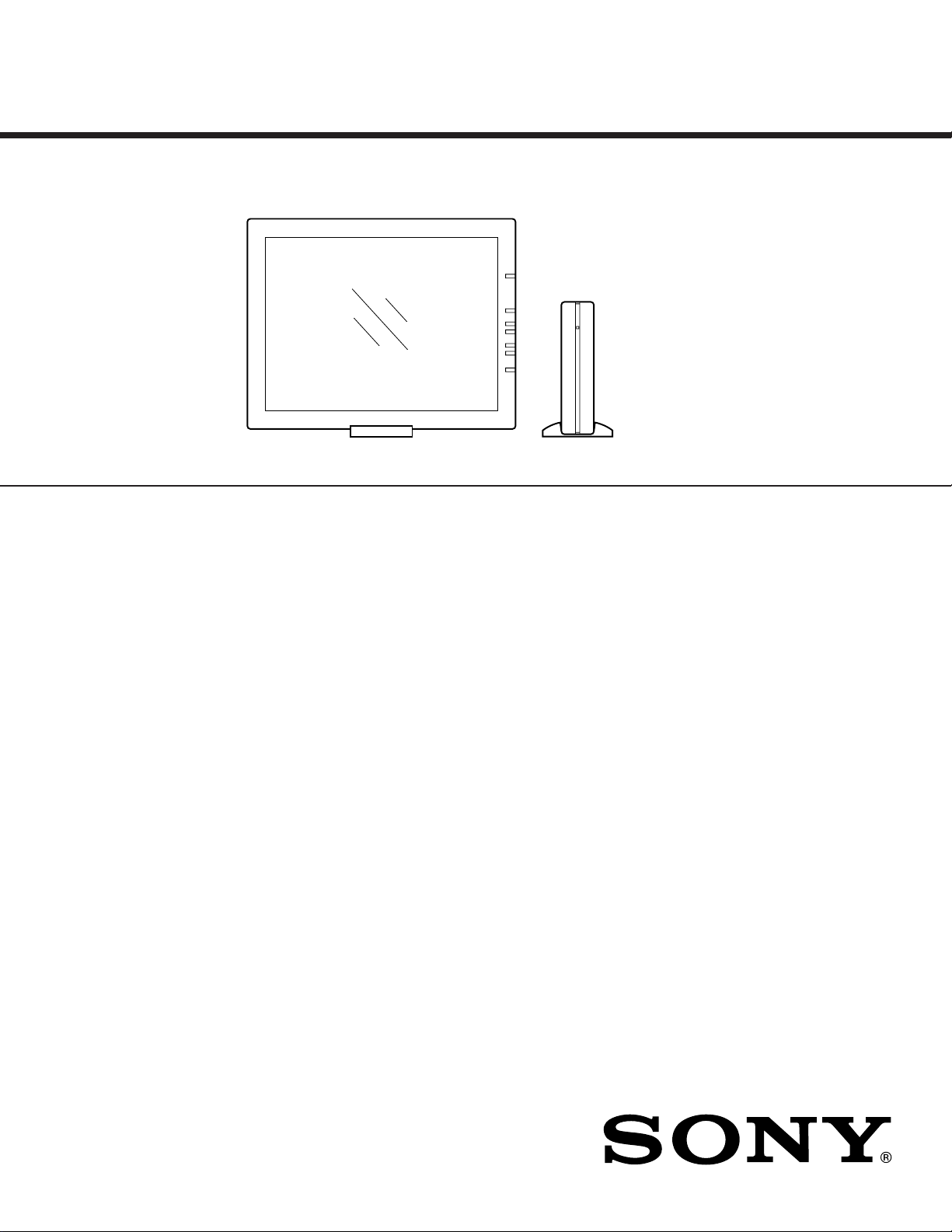
MODEL NAME : SDM-N50PS
SERVICE MANUAL
PARTS No. : 9-978-678-02
* Blue characters are linking.
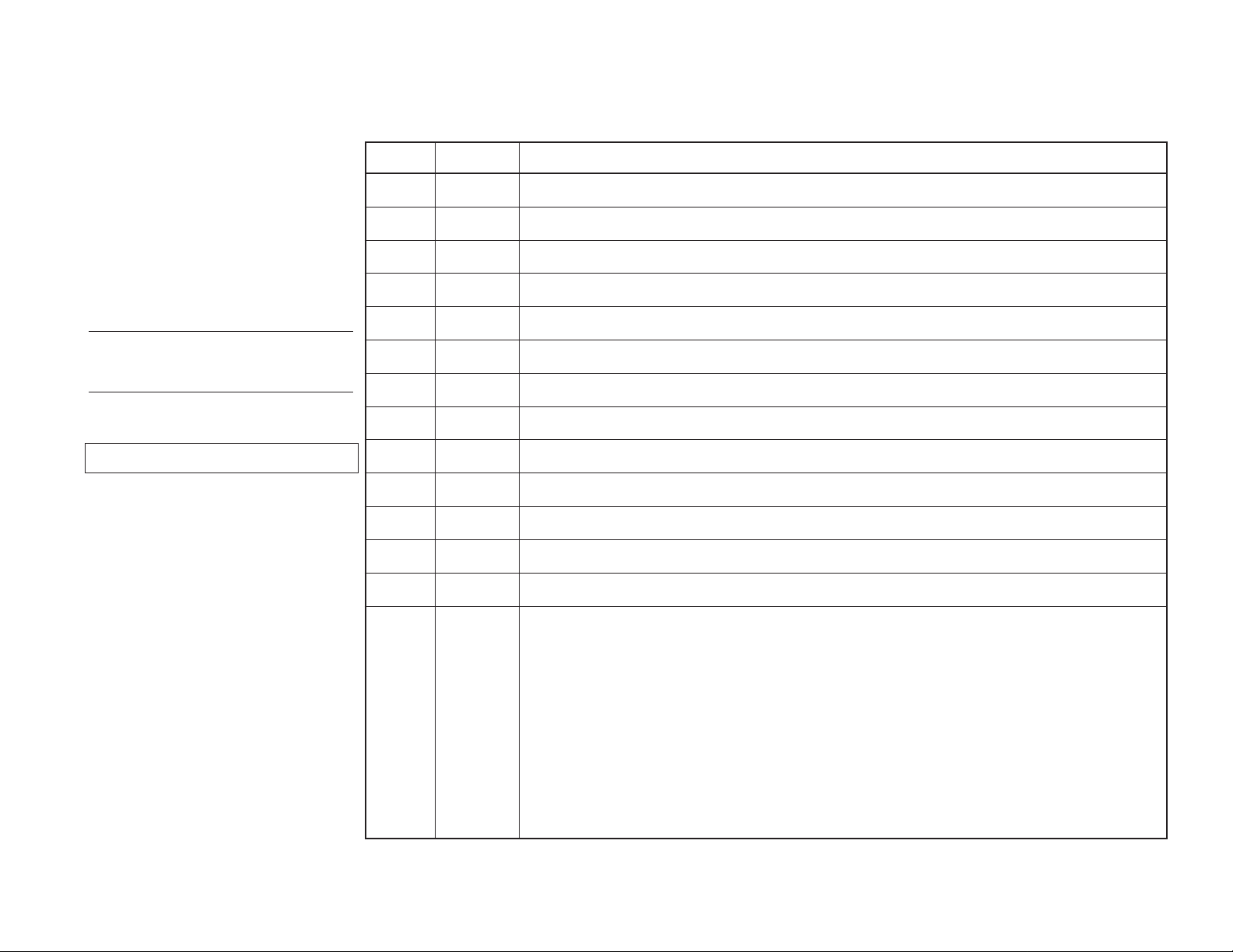
# No. DATA CONTENTS
#1 2001.1 MAIN BLOCK ASSY was re g istered as a service part. (P.5-2)
SERVICE MANUAL
pg
y
• LCD display
• Media engine
• Display stand
• Media engine stand
• Power cord
• System connecting cable (2 m)
(applicable cable type: DP-2)
• HD15 (RGB) video signal cable
• Audio cord (stereo miniplug)
• Macintosh adapter
• Windows Monitor Information Disk/Utility Disk
• Macintosh Utility Disk
• Software for use when installing the display vertically
(WinPortrait/MacPortrait)
• Warranty card
• Notes for Macintosh users
• This instruction manual
SDM-N50PS
US Model
Canadian Model
AEP Model
Chassis No. SCC-L32B-A
LCD panel Panel type: a-Si TFT Active Matrix
Input signal format RGB operating frequency*
Resolution Horizontal: Max.1024 dots
Input signal levels RGB video signal
Headphones jack Stereo minijack
AUDIO IN jack Stereo minijack
Power requirements 100 – 240 V, 50 – 60 Hz,
Power consumption Max. 28 W
Operating temperature 5 – 35
Dimensions (width/height/depth)
MICROFILM
Picture size: 15 inch (38 cm)
Horizontal: 30 – 61 kHz
Vertical: 48 – 85 Hz (only XGA mode
at 75 Hz)
Vertical: Max.768 lines
0.700 Vp-p, 75 Ω, positive
SYNC signal
TTL level, 2 kΩ,
positive or negative
(Separate horizontal and vertical,
or composite sync)
0.3 Vp-p, 75Ω, negative
(Sync on green)
Accepts impedance of more than 16Ω
Accepts impedance of 47 kΩ
Accepts level 0.5 Vrms
0.45 – 0.25 A
˚
C
Display (without stand):
Approx. 356 × 280 × 26 mm
1
(14
/16 × 11 1/6 × 1 1/16 inches)
Display (with stand, at maximum
angle: 40
˚
):
Approx. 356 × 225 × 203 mm
1
(14
/16 × 8 7/8 × 8 inches)
Media engine (without stand):
Approx. 45 × 180 × 180 mm
3
(1
/4 × 7 1/8 × 7 1/8 inches)
Media engine (with stand):
Approx. 94 × 185 × 180 mm
11
(3
/16 × 7 1/4 × 7 1/8 inches)
TFT LCD COLOR COMPUTER DISPLAY
SPECIFICATIONS
Mass Display (with stand):
Plug & Play DDC1/DDC2B/DDC2Bi
Accessories See page 8.
* Recommended horizontal and vertical timing condition
• Horizontal sync width duty should be more than 4.8% of total
horizontal time or 0.8 µs, whichever is larger.
• Horizontal blanking width should be more than 2.5 µsec.
• Vertical blanking width should be more than 450 µsec.
Design and specifications are subject to change without notice.
ST5
Approx. 1.75 kg (3 lb 140 oz)
Media engine (with stand):
Approx. 0.85 kg (1 lb 14 oz)
CHASSIS
SDM-N50PS
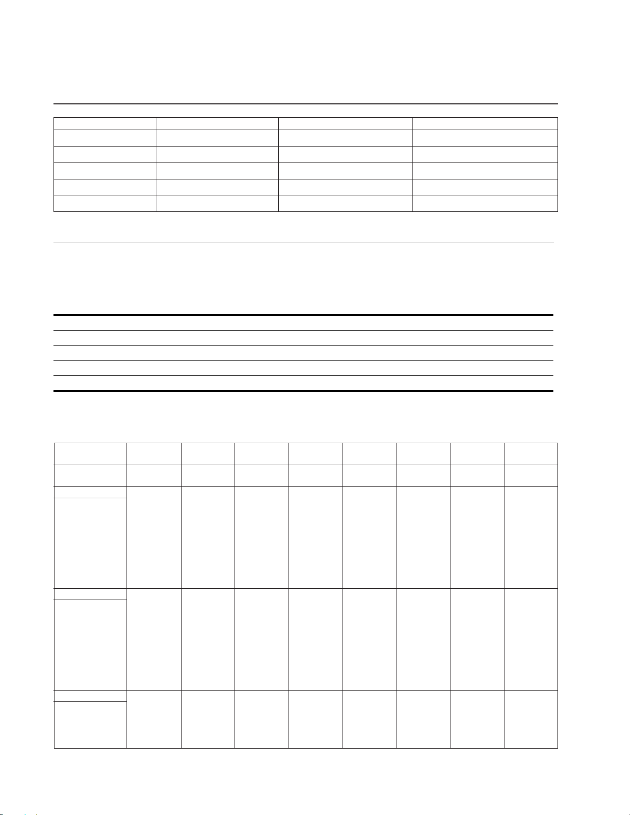
DIAGNOSIS
Factorical preservation register LED LED indicates
Display part trouble SHUTDOWN_LOG1 bit4 (16) Part of the body only Red (0.5 sec) and Off (0.5 sec)
Backlight trouble SHUTDOWN_LOG1 bit2 (4) Parts of the body and the display Amber (0.5 sec) and Off (1.5 sec)
Body temperature trouble SHUTDOWN_LOG1 bit3 (8) Parts of the body and the display Amber (1.0 sec) and Off (1.0 sec)
5V voltage anomalous SHUTDOWN_LOG1 bit5 (32) Parts of the body and the display Amber (1.5 sec) and Off (0.5 sec)
3.3V voltage anomalous SHUTDOWN_LOG1 bit6 (64) Parts of the body and the display Amber (1.5 sec) and Off (0.5 sec)
*Aging mode ...........................................No input signal and press CONT key for longer than 2 second.
Power saving function
This monitor meets the power-saving guidelines set by VESA, NUTEK, and ENERGY STAR. If the monitor is connected to a computer
or graphics board that is DPMS (Display Power Management Signaling) compliant, the monitor will automatically enter the power saving
mode.
Power consumption state Power consumption AC power indicator 1 (power) indicator
normal operation 28 W green green
power saving mode ≤ 3 W orange orange
1 (power): off ≤ 3 W red off
AC power: off 0 W off off
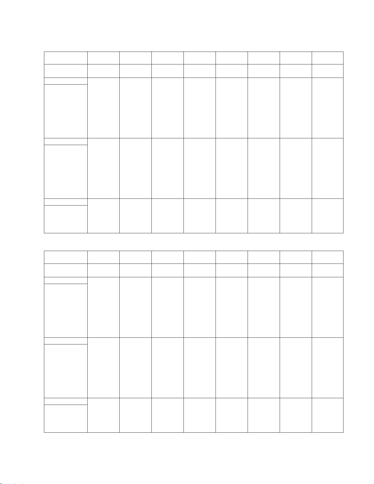
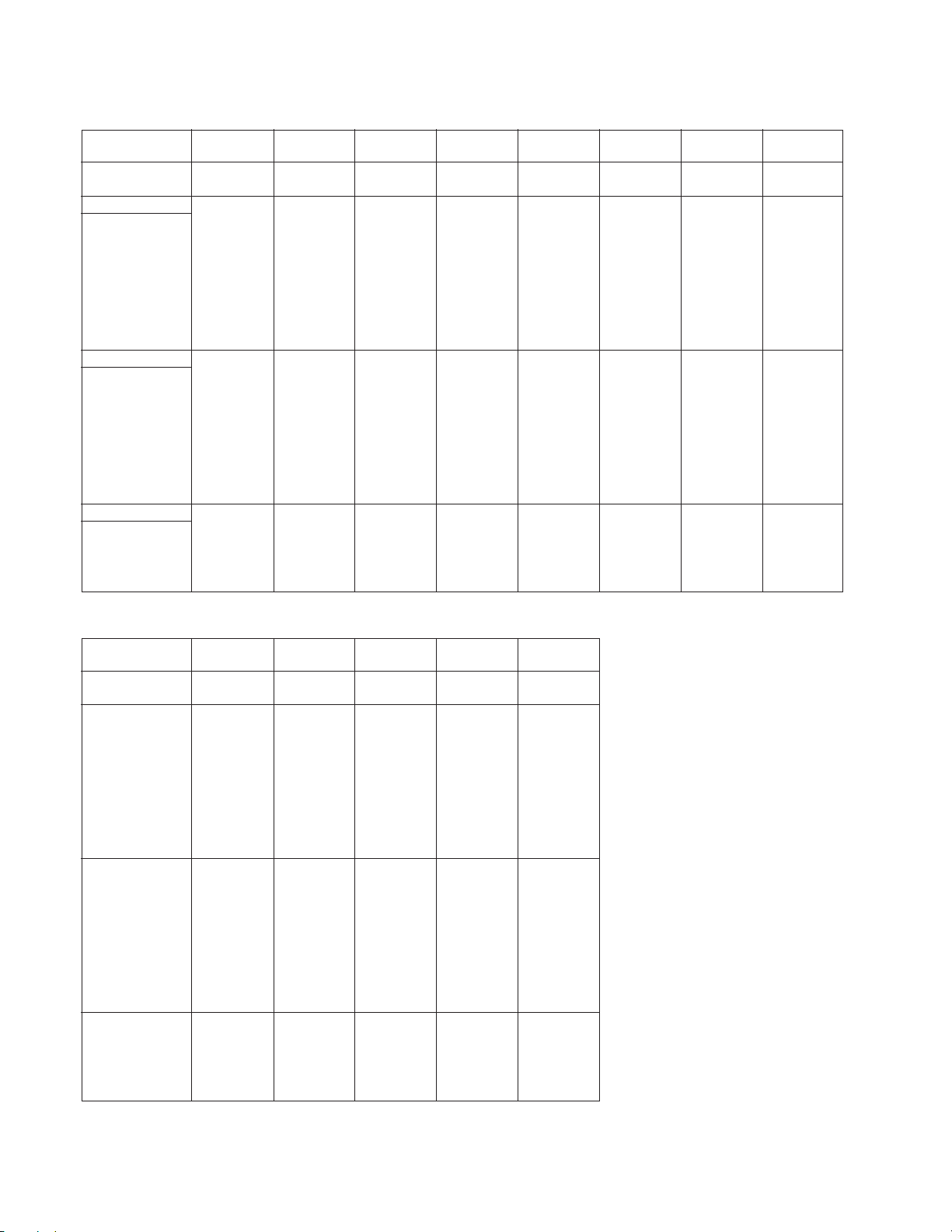
TIMING SPECIFICATION
PRIMARY MODE
MODE AT PRODUCTION
RESOLUTION 640 X 480 640 X 480 640 X 480 640 X 480 720 X 400 720 X 400 720 X 480 720 X 480
CLOCK 25.175 MHz 30.240 MHz 31.500 MHz 36.000 MHz 28.350 MHz 35.500 MHz 35.573 MHz 31.505 MHz
— HORIZONTAL —
H-FREQ 31.469 kHz 35.000 kHz 37.500 kHz 43.269 kHz 31.500 kHz 37.927 kHz 37.683 kHz 35.162 kHz
H. TOTAL 31.778 28.571 26.667 23.111 31.746 26.366 26.537 28.440
H. BLK 6.356 7.407 6.349 5.333 6.349 6.085 6.297 5.586
H. FP 0.636 2.116 0.508 1.556 0.635 1.014 0.450 1.079
H. SYNC 3.813 2.116 2.032 1.556 3.810 2.028 2.024 1.270
H. BP 1.907 3.175 3.810 2.222 1.905 3.042 3.823 3.238
H. ACTIV 25.422 21.164 20.317 17.778 25.397 20.282 20.240 22.854
— VERTICAL —
V. FREQ(Hz) 59.940 Hz 66.667 Hz 75.000 Hz 85.008 Hz 70.156 Hz 85.039 Hz 75.066 Hz 59.901 Hz
V. TOTAL 525 525 500 509 449 446 502 587
V. BLK 45 45 20 29 49 46 22 107
V. FP 10 3 1 1 12 1 2 12
V. SYNC 2 3 3 3 3 3 3 2
V. BP 33 39 16 25 34 42 17 93
V. ACTIV 480 480 480 480 400 400 480 480
— SYNC —
INT(G) NO NO NO NO NO NO NO NO
EXT(H/V)/POLARITY YES N/N YES N/N YES N/N YES N/N YES N/P YES N/P YES N/N YES N/N
EXT(CS)/POLARITY NO NO NO NO NO NO NO NO
INT/NON INT NON INT NON INT NON INT NON INT NON INT NON INT NON INT NON INT
MODE 0 MODE 1 MODE 2 MODE 3 MODE 4 MODE 5 MODE 6 MODE 7
usec usec usec usec usec usec usec usec
lines lines lines lines lines lines lines lines
– 2 –
SDM-N50PS
PRIMARY MODE
MODE AT PRODUCTION
RESOLUTION 800 X 600 800 X 600 800 X 600 800 X 600 — — 832 X 624 1024 X 768
CLOCK 36.000 MHz 40.000 MHz 49.500 MHz 56.250 MHz — — 57.285 MHz 65.000 MHz
— HORIZONTAL —
H-FREQ 35.156 kHz 37.879 kHz 46.875 kHz 53.674 kHz — — 46.727 kHz 48.363 kHz
H. TOTAL 28.444 26.400 21.333 18.631 — — 20.110 20.677
H. BLK 6.222 6.400 5.172 4.409 — — 5.586 4.923
H. FP 0.667 1.000 0.323 0.569 — — 0.559 0.369
H. SYNC 0.889 3.200 1.616 1.138 — — 1.117 2.092
H. BP 4.667 2.200 3.232 2.702 — — 3.910 2.462
H. ACTIV 22.222 20.000 16.162 14.222 — — 14.524 15.754
— VERTICAL —
V. FREQ(Hz) 56.250 Hz 60.317 Hz 75.000 Hz 85.061 Hz — — 74.553 Hz 60.004 Hz
V. TOTAL 625 628 625 631 — — 667 806
V. BLK 25 28 25 31 — — 43 38
V. FP 1 1 1 1 — — 3 3
V. SYNC 2 4 3 3 — — 3 6
V. BP 22 23 21 27 — — 37 29
V. ACTIV 600 600 600 600 — — 624 768
— SYNC —
INT(G) NO NO NO NO — — NO NO
EXT(H/V)/POLARITY YES N/N YES P/P NO P/P YES P/P — — YES N/N YES N/N
EXT(CS)/POLARITY NO NO NO NO — — NO NO
INT/NON INT NON INT NON INT NON INT NON INT — — NON INT NON INT
MODE 8 MODE 9 MODE 10 MODE 11 MODE 12 MODE 13 MODE 14 MODE 15
usec usec usec usec — — usec usec
lines lines lines lines — — lines lines
PRIMARY MODE
MODE AT PRODUCTION
RESOLUTION 1024 X 768 1024 X 768 — 1024 X 768 800 X 600 1024 X 768 1024 X 768 848 X 480
CLOCK 75.000 MHz 78.750 MHz — 80.000 MHz 50.000 MHz 71.640 MHz 80.000 MHz 38.336 MHz
— HORIZONTAL —
H-FREQ 56.476 kHz 60.023 kHz — 60.241 kHz 48.077 kHz 53.946 kHz 60.241 kHz 35.300 kHz
H. TOTAL 17.707 16.660 — 16.600 20.800 18.537 16.600 28.328
H. BLK 4.053 3.657 — 3.800 4.800 4.243 3.800 6.208
H. FP 0.320 0.203 — 0.400 1.120 0.223 0.400 1.409
H. SYNC 1.813 1.219 — 1.200 2.400 2.457 2.200 3.130
H. BP 1.920 2.235 — 2.200 1.280 1.563 1.200 1.669
H. ACTIV 13.653 13.003 — 12.800 16.000 14.294 12.800 22.120
— VERTICAL —
V. FREQ(Hz) 70.069 Hz 75.029 Hz — 74.927 Hz 72.188 Hz 66.110 Hz 74.927 Hz 59.932 Hz
V. TOTAL 806 800 — 804 666 816 804 589
V. BLK 38 32 — 36 66 48 36 109
V. FP 3 1 — 3 37 8 3 11
V. SYNC 6 3 — 3 6 4 3 3
V. BP 29 28 — 30 23 36 30 95
V. ACTIV 768 768 — 768 600 768 768 480
— SYNC —
INT(G) NO NO — NO NO NO NO NO
EXT(H/V)/POLARITY YES N/N YES P/P — YES N/N YES N/N YES N/N YES N/N YES N/N
EXT(CS)/POLARITY NO NO — NO NO NO NO NO
INT/NON INT NON INT NON INT — NON INT NON INT NON INT NON INT NON INT
MODE 16 MODE 17 MODE 18 MODE 19 MODE 20 MODE 21 MODE 22 MODE 23
usec usec — usec usec usec usec usec
lines lines — lines lines lines lines lines
– 3 –
SDM-N50PS
PRIMARY MODE
MODE AT PRODUCTION
RESOLUTION 640 X 400 640 X 350 640 X 400 640 X 480 1024 X 768 640 X 400 720 X 400 800 X 600
CLOCK 25.180 MHz 31.500 MHz 31.500 MHz 31.500 MHz 65.000 MHz 24.870 MHz 28.320 MHz 36.000 MHz
— HORIZONTAL —
H-FREQ 31.475 kHz 37.861 kHz 37.861 kHz 37.861 kHz 48.077 kHz 30.478 kHz 31.467 kHz 35.156 kHz
H. TOTAL 31.771 26.413 26.413 26.413 20.800 32.811 31.780 28.444
H. BLK 6.354 6.095 6.095 6.095 5.046 7.077 6.356 6.222
H. FP 0.953 1.016 1.016 0.762 0.462 0.322 0.636 0.167
H. SYNC 2.542 2.032 2.032 1.270 1.477 3.860 3.814 5.111
H. BP 2.859 3.048 3.048 4.063 3.108 2.895 1.907 0.944
H. ACTIV 25.417 20.317 20.317 20.317 15.754 25.734 25.424 22.222
— VERTICAL —
V. FREQ(Hz) 70.100 Hz 85.080 Hz 85.080 Hz 72.809 Hz 59.797 Hz 59.996 Hz 50.026 Hz 56.160 Hz
V. TOTAL 449 445 445 520 804 508 629 626
V. BLK 49 95 45 40 36 108 229 26
V. FP 11 32 1 9 3 37 102 2
V. SYNC 2 3 3 3 4 2 2 1
V. BP 36 60 41 28 29 69 125 23
V. ACTIV 400 350 400 480 768 400 400 600
— SYNC —
INT(G) NO NO NO NO NO NO NO NO
EXT(H/V)/POLARITY YES N/N YES P/N YES N/P YES N/N YES N/N YES N/N YES N/N YES N/N
EXT(CS)/POLARITY NO NO NO NO NO NO NO NO
INT/NON INT NON INT NON INT NON INT NON INT NON INT NON INT NON INT NON INT
MODE 24 MODE 25 MODE 26 MODE 27 MODE 28 MODE 29 MODE 30 MODE 31
usec usec usec usec usec usec usec usec
lines lines lines lines lines lines lines lines
PRIMARY MODE
MODE AT PRODUCTION
RESOLUTION 800 X 600 1024 X 768 1024 X 768 1024 X 768 800 X 600
CLOCK 50.000 MHz 64.000 MHz 65.000 MHz 64.000 MHz 39.530 MHz
— HORIZONTAL —
H-FREQ 48.828 kHz 48.780 kHz 48.363 kHz 48.485 kHz 37.434 kHz
H. TOTAL 20.480 20.500 20.677 20.625 26.714
H. BLK 4.480 4.500 4.923 4.625 6.476
H. FP 0.960 1.000 0.615 1.219 1.012
H. SYNC 1.600 1.500 3.200 1.219 2.530
H. BP 1.920 2.000 1.108 2.188 2.934
H. ACTIV 16.000 16.000 15.754 16.000 20.238
— VERTICAL —
V. FREQ(Hz) 66.888 Hz 59.561 Hz 60.078 Hz 59.637 Hz 59.608 Hz
V. TOTAL 730 819 805 813 628
V. BLK 130 51 37 45 28
V. FP 48 12 3 39 5
V. SYNC 6 6 3 3 1
V. BP 76 33 31 3 22
V. ACTIV 600 768 768 768 600
— SYNC —
INT(G) YES NO NO NO NO
EXT(H/V)/POLARITY YES N/N YES N/N YES N/N YES N/N YES N/N
EXT(CS)/POLARITY NO NO NO NO NO
INT/NON INT NON INT NON INT NON INT NON INT NON INT
MODE 32 MODE 33 MODE 34 MODE 35 MODE 36
usec usec usec usec usec
lines lines lines lines lines
2000.1.11 VER.
– 4 –
SAFETY CHECK-OUT
r
SDM-N50PS
After correcting the original service problem, perform the following safety checks before releasing the set to the customer:
1. Check the area of your repair for unsoldered or poorly-soldered connections. Check the entire board surface for solder
splashes and bridges.
2. Check the interboard wiring to ensure that no wires are
“pinched” or contact high-wattage resistors.
3. Check that all control knobs, shields, covers, ground straps,
and mounting hardware have been replaced. Be absolutely
certain that you have replaced all the insulators.
4. Look for unauthorized replacement parts, particularly transistors, that were installed during a previous repair. Point
them out to the customer and recommend their replacement.
5. Look for parts which, though functioning, show obvious
signs of deterioration. Point them out to the customer and
recommend their replacement.
6. Check the line cords for cracks and abrasion. Recommend
the replacement of any such line cord to the customer.
7. Check the B+ and HV to see if they are specified values.
Make sure your instruments are accurate; be suspicious of
your HV meter if sets always have low HV.
8. Check the antenna terminals, metal trim, “metallized”
knobs, screws, and all other exposed metal parts for AC
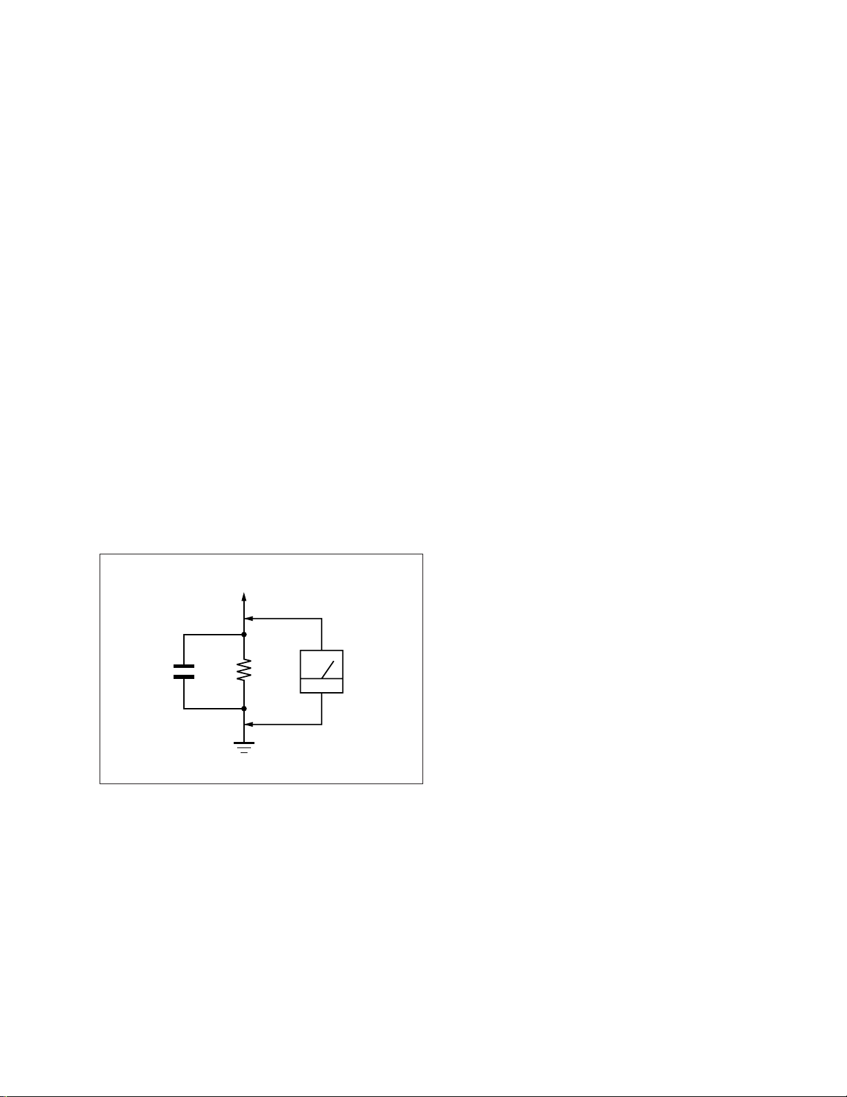
Leakage. Check leakage as described below.
To Exposed Metal
Parts on Set
AC
0.15 µF
1.5 k
Ω
Voltmete
(0.75 V)
LEAKAGE TEST
The AC leakage from any exposed metal part to earth ground
and from all exposed metal parts to any exposed metal part having a return to chassis, must not exceed 0.5 mA (500
microampers).
Leakage current can be measured by any one of three methods.
1. A commercial leakage tester, such as the Simpson 229 or
RCA WT-540A. Follow the manufacturers’ instructions to
use these instruments.
2. A battery-operated AC milliammeter. The Data Precision
245 digital multimeter is suitable for this job.
3. Measuring the voltage drop across a resistor by means of a
VOM or battery-operated AC voltmeter. The “limit” indication is 0.75 V, so analog meters must have an accurate lowvoltage scale. The Simpson 250 and Sanwa SH-63Trd are
examples of a passive VOMs that are suitable. Nearly all
battery operated digital multimeters that have a 2 V AC
range are suitable. (See Fig. A)
WARNING!!
NEVER TURN ON THE POWER IN A CONDITION IN
WHICH THE DEGAUSS COIL HAS BEEN REMOVED.
SAFETY-RELATED COMPONENT WARNING!!
COMPONENTS IDENTIFIED BY SHADING AND MARK
¡ ON THE SCHEMATIC DIAGRAMS, EXPLODED
VIEWS AND IN THE PARTS LIST ARE CRITICAL FOR
SAFE OPERATION. REPLACE THESE COMPONENTS
WITH SONY PARTS WHOSE PART NUMBERS APPEAR AS SHOWN IN THIS MANUAL OR IN SUPPLEMENTS PUBLISHED BY SONY. CIRCUIT ADJUSTMENTS THAT ARE CRITICAL FOR SAFE OPERATION
ARE IDENTIFIED IN THIS MANUAL. FOLLOW THESE
PROCEDURES WHENEVER CRITICAL COMPONENTS
ARE REPLACED OR IMPROPER OPERATION IS SUSPECTED.
Earth Ground
Fig. A. Using an AC voltmeter to check AC leakage.
AVERTISSEMENT!!
NE JAMAIS METTRE SOUS TENSION QUAND LA
BOBINE DE DEMAGNETISATION EST ENLEVÉE.
ATTENTION AUX COMPOSANTS RELATIFS À LA
SÉCURITÉ!!
LES COMPOSANTS IDENTIFIÉS PAR UNE TRAME ET
UNE MARQUE
¡ SONT CRITIQUES POUR LA SÉCURITÉ.
NE LES REMPLACER QUE PAR UNE PIÈCE PORTANT LE
NUMÉRO SPECIFIÉ. LES RÉGLAGES DE CIRCUIT DONT
L’IMPORTANCE EST CRITIQUE POUR LA SÉCURITÉ DU
FONCTIONNEMENT SONT IDENTIFIÉS DANS LE
PRÉSENT MANUEL. SUIVRE CES PROCÉDURES LORS
DE CHAQUE REMPLACEMENT DE COMPOSANTS CRITIQUES, OU LORSQU’UN MAUVAIS FONCTIONNEMENT
EST SUSPECTÉ.
– 5 –

SDM-N50PS
TABLE OF CONTENTS
Section Title Page
1. GENERAL .................................................................. 1-1
2. DISASSEMBLY
2-1. Rear Cover Removal ........................................... 2-1
2-2. Jack Cover Removal............................................. 2-1
2-3. B Board Removal ................................................ 2-2
2-4. H Board Removal................................................. 2-2
2-5. LCD Module (TFT) Removal .............................. 2-2
2-6. A Board Removal................................................. 2-3
2-7. G Board Removal................................................. 2-3
3. ADJUSTMENTS ...................................................... 3-1
4. DIAGRAMS
4-1. Block Diagrams.................................................... 4-1
4-2. Circuit Boards Location ...................................... 4-7
4-3. Schematic Diagrams and Printed Wiring Boards ... 4-8
(1) Schematic Diagrams of A (P1-P3) Boards .......... 4-9
(2) Schematic Diagrams of B (P1-P4) Boards .......... 4-23
(3) Schematic Diagrams of H Board.......................... 4-33
(4) Schematic Diagrams of G (P1-P2) Boards .......... 4-35
4-4. Semiconductors ................................................... 4-41
5. EXPLODED VIEWS
5-1. Display ................................................................. 5-1
5-2. Chassis ................................................................. 5-2
5-3. Packing Materials ................................................ 5-3
6. ELECTRICAL PARTS LIST ............................ 6-1
– 6 –
SECTION 1
The operating instructions mentioned here are partial abstracts
from the Operating Instruction Manual. The page numbers of
the Operating Instruction Manual remein as in the manual.
4
Precautions
Warning on power connections
• Use the supplied power cord. If you use a different power cord,
be sure that it is compatible with your local power supply.
For the customers in the U.S.A.
If you do not use the appropriate cord, this monitor will not
conform to mandatory FCC standards.
For the customers in the UK
If you use the monitor in the UK, please use the appropriate UK
power cord.
Installation
Do not install or leave the monitor:
• In places subject to extreme temperatures, for example near a
radiator, heating vent, or in direct sunlight. Subjecting the
monitor to extreme temperatures, such as in an automobile
parked in direct sunlight or near a heating vent, could cause
deformations of the casing or malfunctions.
• In places subject to mechanical vibration or shock.
• Near any equipment that generates a strong magnetic field,
such as a TV or various other household appliances.
• In places subject to inordinate amounts of dust, dirt, or sand, for
example near an open window or an outdoor exit. If setting up
temporarily in an outdoor environment, be sure to take
adequate precautions against airborne dust and dirt. Otherwise
irreparable malfunctions could occur.
Handling the LCD screen
• Do not leave the LCD screen facing the sun as it can damage
the LCD screen. Take care when you place the monitor by a
window.
• Do not push on or scratch the LCD screen. Do not place a heavy
object on the LCD screen. This may cause the screen to lose
uniformity or cause LCD panel malfunctions.
• If the monitor is used in a cold place, a residual image may
appear on the screen. This is not a malfunction. The screen
returns to normal as the temperature rises to a normal operating
level.
• If a still picture is displayed for a long time, a residual image
may appear for a while. The residual image will eventually
disappear.
• The LCD panel becomes warm during operation. This is not a
malfunction.
About the bright points of light or black dots
Bright points of light (red, blue or green) or black dots
may appear on the LCD screen. This is not a
malfunction. The LCD screen is made with highprecision technology and more than 99.99% of the
picture element is intact. However, some of the picture
element may not appear or some of the picture element
may appear constantly.
Replacement of the fluorescent tube
A specially designed fluorescent tube is installed as the lighting
apparatus for this monitor. If the screen becomes dark, unstable,
or does not turn on, replace the fluorescent tube with a new one.
Consult your Sony dealer when replacing the fluorescent tube.
Maintenance
• Be sure to unplug the power cord from the power outlet before
cleaning your monitor.
• Clean the LCD screen with a soft cloth. If you use a glass
cleaning liquid, do not use any type of cleaner containing an
anti-static solution or similar additive as this may scratch the
LCD screen’s coating.
• Clean the cabinet, panel, and controls with a soft cloth lightly
moistened with a mild detergent solution. Do not use any type
of abrasive pad, scouring powder, or solvent, such as alcohol or
benzine.
• Do not rub, touch, or tap the surface of the screen with sharp or
abrasive items such as a ballpoint pen or screwdriver. This type
of contact may result in a scratched picture tube.
• Note that material deterioration or LCD screen coating
degradation may occur if the monitor is exposed to volatile
solvents such as insecticide, or if prolonged contact is
maintained with rubber or vinyl materials.
Transporting
• When transporting, first disconnect all cables from the monitor,
then grasp the monitor with both hands to carry it. Be careful
when transporting the monitor, if dropped it may cause injury
or damage.
• When you transport this monitor for repair or shipment, use the
original carton and packing materials.
Disposal of the monitor
•
Do not dispose of this monitor with general
household waste.
•
The fluorescent tube used in this monitor contains
mercury. Disposal of this monitor must be carried out
in accordance to the regulations of your local
sanitation authority.
The equipment should be installed near an easily accessible
outlet.
Example of plug types
for 100 to 120 V AC for 200 to 240 V AC for 240 V AC only
5
GB
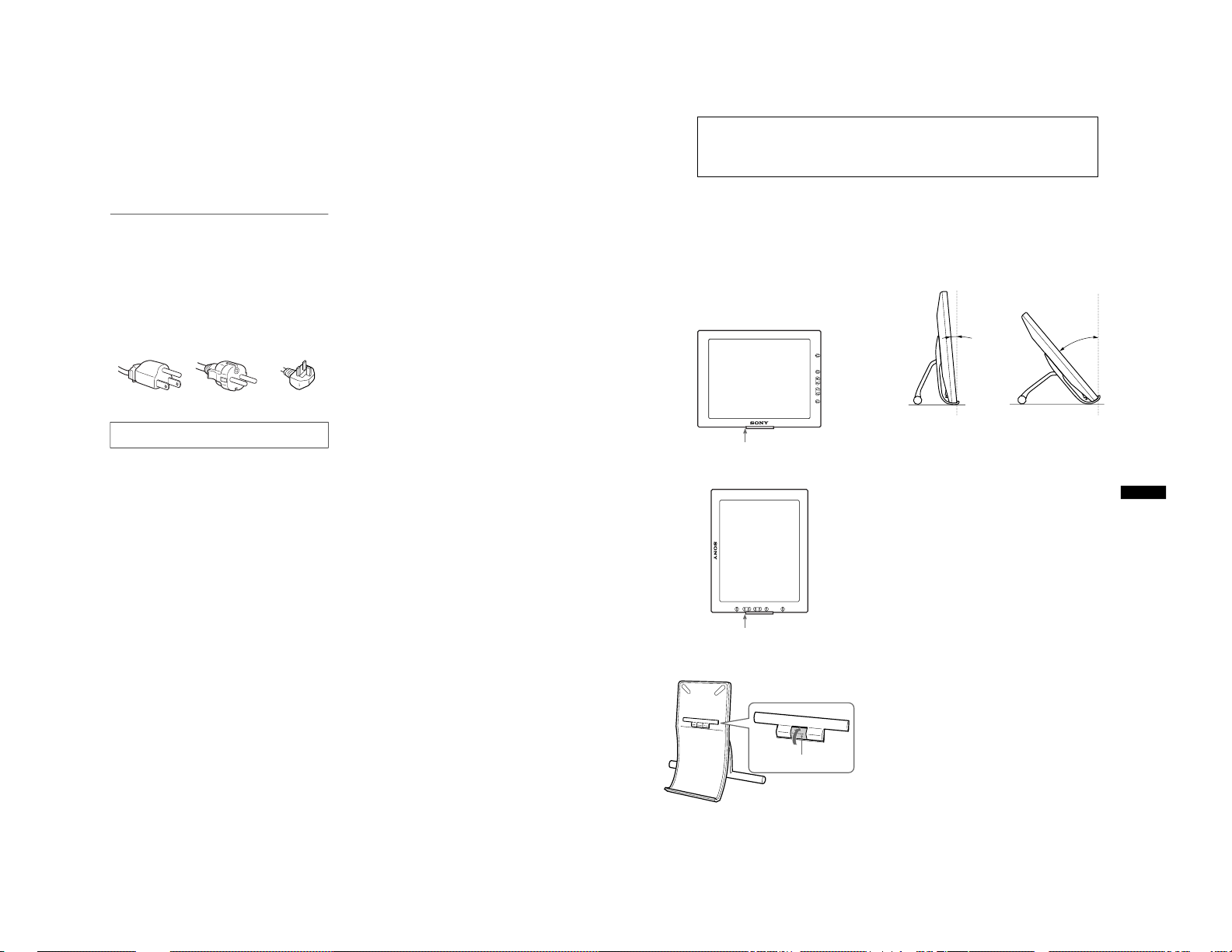
To install the display horizontally or vertically
This display can be installed either horizontally or vertically using
the supplied display stand.
Open the display stand until the click sound is heard.
Put the display on the stand, aligning the mark which shows the
stand position on the display.
To switch to the horizontal or vertical viewing position, see
page 10.
To close the display stand
While sliding the stopper up, close the display stand.
To adjust the angle
This display can be adjusted within the angles shown below with
the supplied display stand.
To adjust the angle, hold the front base and push (or pull) the rear
leg outward (or inward) until the desired angle is attained.
To install the display on the display stand, put it softly.
Note
Do not exceed the angles shown above, otherwise the display could fall
and cause damage or a malfunction.
To use the display comfortably
This display is designed so that you can set it up at a comfortable
viewing angle. Adjust the viewing angle of your display
according to the height of the desk and chair, and so that light is
not reflected from the screen to your eyes.
Vertical installation
Horizontal installation
The stand positioning mark
The stand positioning mark
The stopper
20˚
40˚
GENERAL
1-1
6
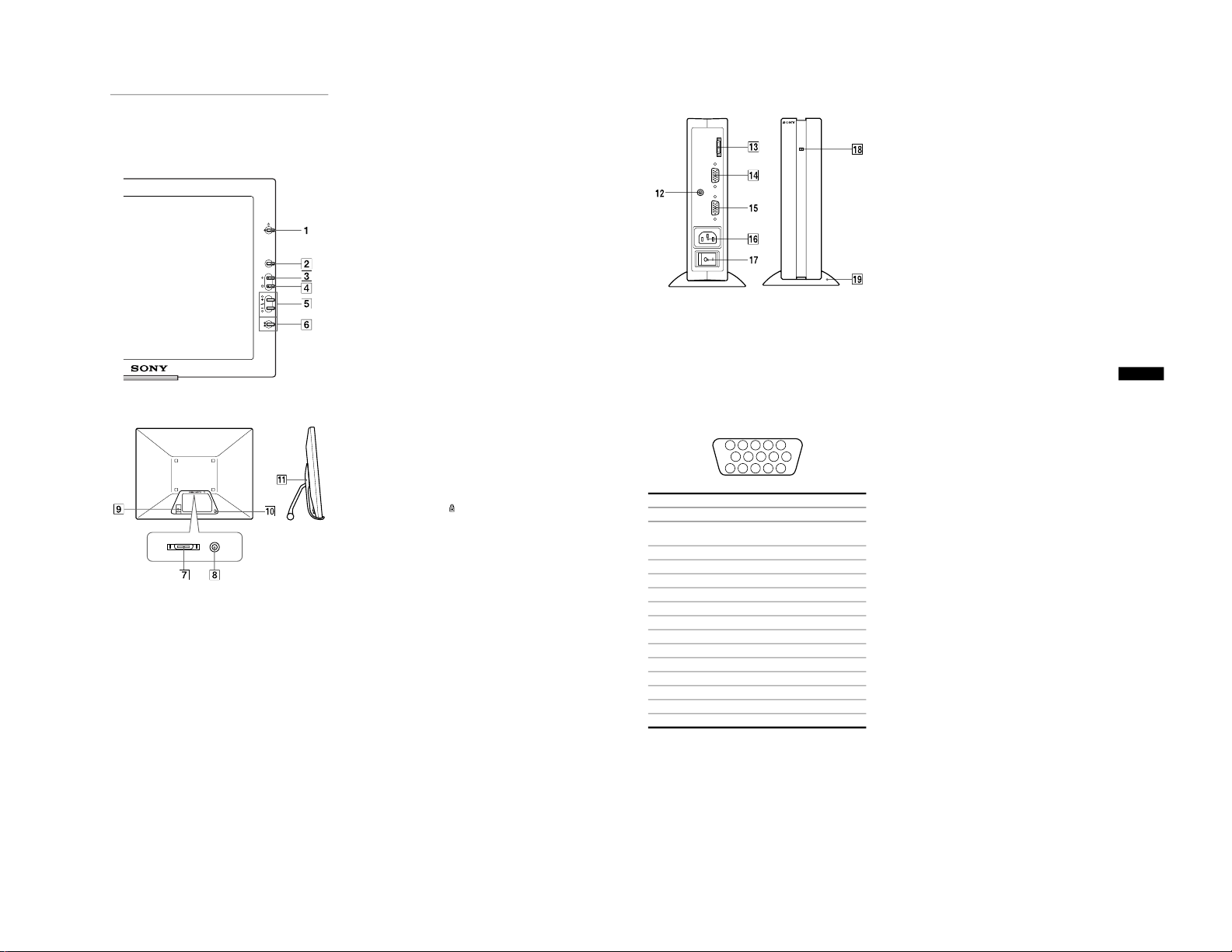
Identifying parts and controls
See the pages in parentheses for further details.
1 1
(Power) switch and indicator (pages 9, 17, 21)
This switch turns the display on and off.
The indicator lights up in green when the monitor is turned on.
The indicator lights up in orange when the monitor is in power
saving mode.
2
MENU button (page 13)
This button displays the main menu.
3 6
(contrast) button (page 13)
This button displays the CONTRAST menu.
4 8
(brightness) button (page 13)
This button displays the BRITGHTNESS menu.
5 2
(volume) +/– and M (+)/ m (–) buttons
(pages 10, 13)
These buttons display the VOLUME menu and function as
the M (+)/ m (–) buttons when selecting the menu items and
making adjustments.
6
INPUT and OK button, and indicator (pages 11, 13)
This button selects the INPUT 1 or INPUT 2 video input
signal. The input signal and corresponding input indicator
change each time you press this button.
This button also functions as the OK button when displaying
the menu on the screen.
7
SYSTEM CONNECTOR (page 8)
This connector inputs signals from the media engine when the
display and the media engine are connected with a system
connecting cable.
8
Headphones jack (page 10)
This jack outputs audio signals to the headphones.
9
Cable holder
This holder is used to keep the system connecting cable out of
the way.
0
Security Lock Hole ( )
The security lock hole should be applied with the Kensington
Micro Saver Security System.
Micro Saver Security System is a trademark of Kensington.
qa
Display stand
This stand is used to install the display.
MENU
INPUT
OK
1
2
LCD display
Rear/Side
Front
7
GB
Media engine
qs
AUDIO IN jack (page 10)
This jack inputs audio signals when connecting to the audio
output jack of the computer or other audio equipment.
qd
SYSTEM CONNECTOR (TO DISPLAY) (page 8)
This connector outputs signals to the display when the display
and the media engine are connected with a system connecting
cable.
qf
HD15 (RGB) input 1 connector (INPUT1) (page 8)
This connector inputs RGB video signals (0.700 Vp-p,
positive) and SYNC signals.
* DDC (Display Data Channel) is a standard of VESA.
qg
HD15 (RGB) input 2 connector (INPUT2) (page 8)
This connector inputs RGB video signals (0.700 Vp-p,
positive) and SYNC signals. The pin assignment is the same
as qf .
qh
AC IN connector (page 9)
This connector provides AC power to the monitor.
qj
AC power switch (page 9)
This switch turns the media engine on and off. When the AC
power switch is turned on or off, the display automatically
turns on or off.
qk
AC power indicator (page 17)
This indicator lights up in green when the media engine is
turned on. The indicator lights up in red when the display is
turned off with the media engine on. The indicator lights up in
orange when the monitor is in the power saving mode.
ql
Media engine stand
This stand is used to install the media engine vertically.
Caution
Be sure to install the media engine vertically shown as left. Installing the
media engine lying flat may block ventilation, and may cause a
malfunction.
Pin No. Signal
1 Red
2 Green
(Sync on Green)
3 Blue
4 ID (Ground)
5 DDC Ground*
6 Red Ground
7 Green Ground
8 Blue Ground
9 DDC + 5V*
10 Ground
11 ID (Ground)
12 Bi-Directional Data (SDA)*
13 H. Sync
14 V. Sync
15 Data Clock (SCL)*
SYSTEM CONNECTER
(
TO DISPLAY
)
INPUT 1
INPUT 2
AUDIO IN
5
4 3 2
1
6789
10
1112
131415
1-2
8
Setup
Before using your monitor, check that the following accessories
are included in your carton:
• LCD display
• Media engine
• Display stand
• Media engine stand
• Power cord
• System connecting cable (2 m)
(applicable cable type: DP-2)
• HD15 (RGB) video signal cable
• Audio cord (stereo miniplug)
• Macintosh adapter
• Windows Monitor Information Disk/Utility Disk
• Macintosh Utility Disk
• Software for use when installing the display vertically
(WinPortrait/MacPortrait)
• Warranty card
• Notes for Macintosh users
• This instruction manual
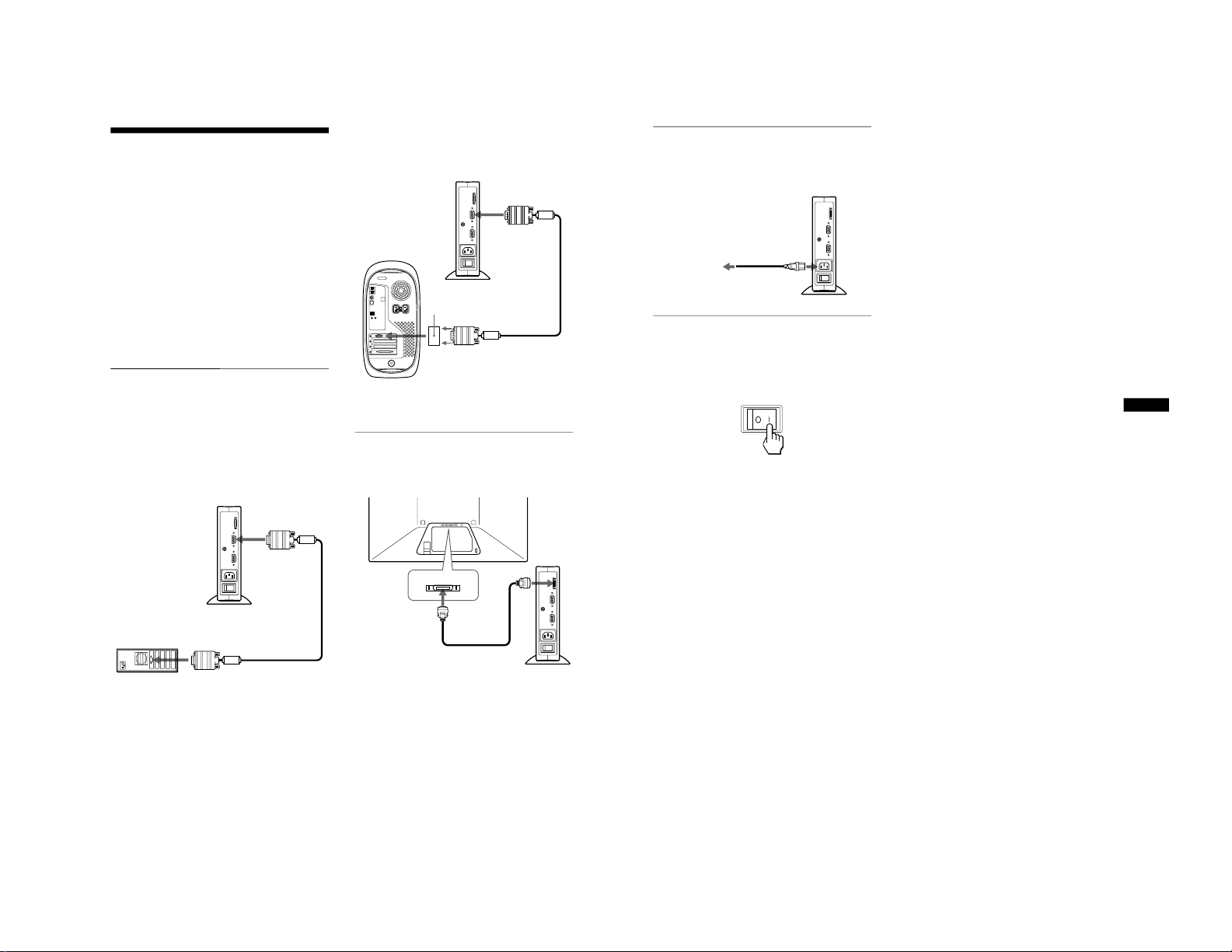
Step 1:Connect the media engine
to your computer
Turn off the media engine and computer before connecting.
Note
Do not touch the pins of the video signal cable connector as this might
bend the pins.
x
Connecting to an IBM PC/AT or compatible
computer
x
Connecting to a Macintosh or compatible
computer
* Refer to the supplied “Notes for Macintosh users” for further details.
Step 2:Connect the display and
media engine
Turn off the display and media engine before connecting.
Caution
Be sure to install the media engine vertically shown as above. Installing
the media engine lying flat may block ventilation, and may cause a
malfunction.
Note
Grasp the plug when connecting the cable.
to INPUT1 or
INPUT2 connector
HD15 (RGB) video
signal cable (supplied)
to video output
IBM PC/AT or
compatible computer
IBM PC/AT or
compatible computer
Use the supplied Macintosh adapter.
to INPUT1 or
INPUT2 connector
Macintosh adapter
(supplied)
*
HD15 (RGB) video
signal cable (supplied)
to video output
Macintosh or
compatible computer
to SYSTEM
CONNECTOR
of the media
engine
system connecting
cable (2 m) (supplied)
to SYSTEM
CONNECTOR of
the display
9
GB
Step 3:Connect the power cord
With the display, media engine, and computer switched off,
first connect the power cord to the media engine, then connect it
to a power outlet.
Step 4:Turn on the monitor and
computer
1
Turn on the media engine.
The display automatically turns on. The indicators of the
display and media engine light up in green.
2
Turn on the computer.
The installation of your monitor is complete. If necessary, use the
monitor’s controls to adjust the picture.
If no picture appears on your screen
• Check that the monitor is correctly connected to the computer.
• Check that the media engine is on.
• If NO INPUT SIGNAL appears on the screen, the computer is
in the power saving mode. Try pressing any key on the
keyboard or moving the mouse.
• If CABLE DISCONNECTED appears on the screen, try
changing the input signal (page 11), and check that the video
input cable is properly connected.
• If OUT OF SCAN RANGE appears on the screen, reconnect
the old monitor. Then adjust the computer’s graphic board so
that the horizontal frequency is between 30 – 61 kHz, and the
vertical frequency is between 48 – 85 Hz (only XGA mode at
75 Hz).
For more information about the on-screen messages, see “Trouble
symptoms and remedies” on page 19.
For customers using Windows 95/98
To maximize the potential of your monitor, install the new model
information file from the supplied Windows Monitor Information Disk
onto your PC.
This monitor complies with the “VESA DDC” Plug & Play standard. If
your PC/graphics board complies with DDC, select “Plug & Play Monitor
(VESA DDC)” or this monitor’s model name as the monitor type in the
“Control Panel” of Windows 95/98. If your PC/graphics board has
difficulty communicating with this monitor, load the Windows Monitor
Information Disk and select this monitor’s model name as the monitor
type.
For customers using Windows NT4.0
Monitor setup in Windows NT4.0 is different from Windows 95/98 and
does not involve the selection of monitor type. Refer to the Windows
NT4.0 instruction manual for further details on adjusting the resolution,
refresh rate (vertical frequency), and number of colors.
Adjusting the monitor’s resolution and color number
Adjust the monitor’s resolution and color number by referring to your
computer’s instruction manual. The color number may vary according to
your computer or graphics board. The color palette setting and the actual
number of colors are as follows:
• High Color (16 bit) t 65,536 colors
• True Color (24 bit) t about 16.77 million colors
In true color mode (24 bit), speed may be slower.
to a power outlet
power cord (supplied)
to AC IN
1-3

10
Installing the display vertically
This display can be installed either horizontally or vertically using
the supplied display stand.
To switch to the horizontal or vertical viewing
position
First install the supplied WinPortrait (for Windws 95/98 and
NT4.0) or MacPortrait (for Macintosh). To switch the view, press
Shift + Ctrl + R on the keyboard. For more information, see the
supplied software’s instruction manual.
To install the display horizontally or vertically
Open the display stand until the click sound is heard.
Put the display on the stand, aligning the mark which shows the
stand position on the display.
To close the display stand
While sliding the stopper up, close the display stand.
Using the headphones
You can listen to the audio signals from your computer or other
audio equipment using headphones.
Connect the AUDIO IN jack to the audio output jack of your
computer or other audio equipment using the supplied audio cord.
Adjusting the volume
1
Press the 2 +/– buttons.
The VOLUME menu appears on the screen.
2
Press the 2 +/– button to adjust the volume.
The menu automatically disappears after about 3 seconds.
Notes
• You cannot adjust the volume when displaying the main menu on the
screen.
• When your monitor is in power saving mode, no sound comes from the
headphones.
Vertical installation
Horizontal installation
The stand positioning mark
The stand positioning mark
The stopper
VOLUME
40
,
11
GB
Selecting the on-screen menu
language (LANGUAGE)
English, German, French, Spanish, Italian, and Japanese versions
of the on-screen menus are available. The default setting is
English.
1
Press the MENU button.
2
Press the M (+)/ m (–) buttons to select m .
3
Press the M (+)/ m (–) buttons to select
(LANGUAGE) and press the OK button.
4
Press the M (+)/ m (–) button to select a language.
• ENGLISH
• DEUTSCH: German
• FRANÇAIS: French
• ESPAÑOL: Spanish
• ITALIANO: Italian
• : Japanese
To close the menu
Press the MENU button once to return to normal viewing. If no buttons
are pressed, the menu closes automatically after about 30 seconds.
Selecting the input signal
You can connect two computers to this monitor using the INPUT
1 and INPUT 2 connectors. To select one of the two computers,
use the INPUT button.
Press the INPUT button.
The input signal and corresponding input indicator, “1” (INPUT
1) or “2” (INPUT 2) change each time you press this button.
Notes
• You cannot select the input signal when displaying the main menu on
the screen.
• If no signal is input to the selected connector, NO INPUT SIGNAL or
CABLE DISCONNECTED appears on the screen. After a few seconds,
the monitor enters the power saving mode. If this happens, select the
other connector using the INPUT button.
16
EXI T
PHASE
MENU
,
OFF
ON
BASS BOOST
EXI T
,
ENGL I S H
DEU TSCH
FRANÇAI S
ESPAÑOL
ITALIANO
LANGUAGE
EXI T
INPUT
OK
1
2
,,
INPUT
OK
1
2
1-4

12
Customizing Your Monitor
You can make numerous adjustments to your monitor using the
on-screen menu.
Navigating the menu
Press the MENU button to display the main menu on your screen.
See page 13 for more information on using the MENU button.
Use the M (+)/ m (–) and OK buttons to select one of the following
menus. See page 13 for more information on using the
M
(+)/ m (–) and OK buttons.
Before making adjustments
Connect the monitor and the computer, and turn them on.
Wait for at least 30 minutes before making adjustments for the
best result.
1
PHASE (page 14)
Select the PHASE menu to
adjust the phase when the
characters or pictures appear
fuzzy throughout the entire
screen. Adjust the phase after
adjusting the pitch.
2
PITCH (page 14)
Select the PITCH menu to
adjust the pitch when the
characters or pictures are
unclear in some areas of the
screen.
3
H CENTER (page 14)
Select the H CENTER menu
to adjust the picture’s
horizontal centering.
MENU
PHASE
,
16
EXI T
PHASE
0
EXI T
PITCH
50
EXI T
HCENTER
4
V CENTER (page 14)
Select the V CENTER menu
to adjust the picture’s vertical
centering.
5
ZOOM (page 15)
Select the ZOOM menu to
adjust the picture’s size
according to the input
signal’s aspect ratio or
resolution.
6
COLOR (page 15)
Select the COLOR menu to
adjust the color tone of the
screen.
7
MENU POSITION
(page 15)
Select the MENU
POSITION to change the onscreen menu position.
8
RESET (page 16)
Select the RESET menu to
reset the adjustments.
9
Option (page 16)
Select m (option) menu to
adjust the monitor’s options.
The options include:
• BASS BOOST
• BACKLIGHT
• POWER SAVE
• LANGUAGE
• MENU LOCK
25
EXI T
VCENTER
ON
OFF
ZOOM
EXI T
9300K
0K
650
5000K
USER
ALDJUST
COLOR
EXI T
MEN NUP
OS I I OT
EXI T
SCREEN
ALL
RESET
RESET
RESET
EXI T
OFF
ON
BASS BOOST
EXI T
13
GB
x
Using the MENU,
M
(+)/ m (–), and OK buttons
1
Display the main menu.
Press the MENU button to display the main menu on your
screen.
2
Select the menu you want to adjust.
Press the M (+)/ m (–) buttons to display the desired menu.
Press the OK button to select the menu item.
3
Adjust the menu.
Press the M (+)/ m (–) buttons to make the adjustment. Then
press the OK button to return to the previous menu.
4
Close the menu.
Press the MENU button once to return to normal viewing. If
no buttons are pressed, the menu closes automatically after
about 30 seconds.
x
Resetting the adjustments
You can reset the adjustments using the RESET menu. See
page 16 for more information on resetting the adjustments.
Adjusting the contrast (CONTRAST)
Contrast adjustment is made using a separate CONTRAST menu
from the main menu (page 12). This setting is stored in memory
for the signal from the currently selected input connector.
1
Press the 6 (contrast) button.
The CONTRAST menu appears on the screen.
Displaying the current input signal
The horizontal and vertical frequencies of the current input signal are
displayed in the CONTRAST and BRIGHTNESS menu.
2
Press the M (+)/ m (–) buttons to adjust the contrast.
The menu automatically disappears after about 3 seconds.
Adjusting the black level of an
image (BRIGHTNESS)
Brightness adjustment is made using a separate BRIGHTNESS
menu from the main menu (page 12). This setting is stored in
memory for the signal from the currently selected input
connector.
1
Press the 8 (brightness) button.
The BRIGHTNESS menu appears on the screen.
2
Press the M (+)/ m (–) buttons to adjust the
brightness.
The menu automatically disappears after about 3 seconds.
If the screen is too bright
Adjust the backlight. For more information about adjusting the
backlight see “Adjusting the backlight” on page 16.
Note
You can adjust neither contrast nor brightness when displaying the main
menu on the screen.
MENU
INPUT
OK
1
2
,
INPUT
OK
1
2
,
MENU
48.4kHz/ 60Hz
CONTRAST
70
Horizontal frequency
of the current input
signal
Vertical frequency of
the current input
signal
48.4kHz/ 60Hz
B NESSRIGHT
50
Horizontal frequency
of the current input
signal
Vertical frequency of
the current input
signal
1-5

14
Eliminating flicker or blurring
(PHASE/PITCH)
When the monitor receives an input signal, the automatic picture
quality function of this monitor is activated. This function
automatically adjusts the phase, pitch, and picture position to
ensure that a clear picture appears on the screen. For more
information about this function, see “Automatic picture quality
adjustment function” on page 17.
For some input signals, this function may not completely adjust
the phase, pitch, and picture position. In this case, you can
manually set these adjustments according the following
instructions. If you manually set these adjustments, they are
stored in memory and automatically recalled whenever the
monitor receives the same input signals.
These settings may have to be repeated if you change the input
signal after reconnecting your computer.
1
Set the resolution to 1024 × 768 on the computer.
2
Load the Utility Disk.
Use the appropriate disk for your computer.
For Windows 95/98
Windows Monitor Information Disk/Utility Disk
For Macintosh
Macintosh Utility Disk
3
Start the Utility Disk and display the test pattern.
For Windows 95/98
Click [Utility Disk]
t
[Windows]/[Utility.exe].
For Macintosh
Click [Utility Disk]
t
[SONY-Utility].
4
Press the MENU button.
The main menu appears on the screen.
5
Press the M(+)/m(–) buttons to select (PITCH)
and press the OK button.
The PITCH menu appears on the screen.
6
Press the M(+)/m(–) buttons to adjust the pitch.
Adjust so that the vertical stripes disappear.
7
Press the OK button.
The main menu appears on the screen.
If horizontal stripes are observed over the entire screen, adjust
the phase as the next step.
8
Press the M(+)/m(–) buttons to select (PHASE)
and press the OK button.
The PHASE menu appears on the screen.
9
Press the M(+)/m(–) buttons to adjust the phase.
Adjust so that the horizontal stripes are at a minimum.
10
Click [END] on the screen to turn off the test pattern.
To reset the automatic picture quality adjustment
Select SCREEN RESET and activate it using the RESET menu. See
page 16 for more information on using the RESET menu.
Adjusting the picture position
(H CENTER/V CENTER)
If the picture is not in the center of the screen, adjust the picture’s
centering as follows.
These settings may have to be repeated if you change the input
signal after reconnecting your computer.
1
Start the Utility Disk and display the test pattern.
Repeat steps 2 and 3 of “Eliminating flicker or blurring
(PHASE/PITCH).”
2
Press the MENU button.
The main menu appears on the screen.
3
Press the M(+)/m(–) buttons to select (H
CENTER) or (V CENTER) and press the OK
button.
The H CENTER or V CENTER menu appears on the screen.
4
Move the picture up, down, left, or right until the
frame at the perimeter of the test pattern
disappears.
Press the M(+)/m(–) buttons to adjust the picture’s
centering using the H CENTER menu for horizontal
adjustment, or the V CENTER menu for vertical
adjustment.
5
Click [END] on the screen to turn off the test pattern.
15
GB
Displaying a low-resolution signal
at the actual resolution (ZOOM)
This monitor is preset at the factory to display pictures on the
screen in full, irrespective of the picture’s mode or resolution.
You can also view the picture at its actual resolution.
1
Press the MENU button.
The main menu appears on the screen.
2
Press the M (+)/ m (–) buttons to select (ZOOM)
and press the OK button.
The ZOOM menu appears on the screen.
3
Press the m (–) button to select OFF.
The input signal is displayed on the screen at its actual
resolution.
To display the picture on the screen in full
Select ON in step 3.
Adjusting the color temperature
(COLOR)
The COLOR settings allow you to adjust the picture’s color
temperature by changing the color level of the white color field.
Colors appear reddish if the temperature is low, and bluish if the
temperature is high.
9300K is generally suitable for word processing and other text
oriented applications, and 6500K is generally suitable for video
images.
You can set the color temperature to 5000K, 6500K, 9300K or
user adjustment.
1
Press the MENU button.
The main menu appears on the screen.
2
Press the M (+)/ m (–) buttons to select (COLOR)
and press the OK button.
The COLOR menu appears on the screen.
3
Press the M (+)/ m (–) buttons to select the desired
color temperature.
The preset color temperatures are 5000K, 6500K, and 9300K.
Since the default setting is 9300K, the whites will change
from a bluish hue to a reddish hue as the temperature is
lowered to 6500K and 5000K.
You can set separate color temperatures for each of the video
input signals.
4
If necessary, fine tune the color temperature.
First press the M (+)/ m (–) buttons to select ADJUST and
press the OK button. Then press the M (+)/ m (–) buttons to
select R (Red) or B (Blue) and press the OK button, and then
press the M (+)/ m (–) buttons to adjust the color temperature.
Since this adjustment changes the color temperature by
increasing or decreasing the R and B components with respect
to G (green), the G component is fixed.
If you fine tune the color temperature, the new color setting is
stored in memory for USER ADJUSTMENT and
automatically recalled whenever USER is selected.
The USER ADJUSTMENT setting is common to both the
input signals. If you change the user adjustment setting for
one input signal, the setting for the other input signal is also
changed.
Changing the menu’s position
(MENU POSITION)
You can change the menu position if it is blocking an image on
the screen.
1
Press the MENU button.
The main menu appears on the screen.
2
Press the M (+)/ m (–) buttons to select (MENU
POSITION) and press the OK button.
The MENU POSITION menu appears on the screen.
3
Press the M (+)/ m (–) buttons to select the desired
position.
There are three positions each for the top of the screen and the
bottom of the screen, and one for the screen center.
R168
G170
B175
EXI T
USER ADJ UST TMEN
1-6

16
Resetting the adjustments (RESET)
You can reset the adjustments.
1
Press the MENU button.
The main menu appears on the screen.
2
Press the M (+)/ m (–) buttons to select 0 (RESET)
and press the OK button.
The RESET menu appears on the screen.
You can reset the adjustment data in either of the following
two ways:
Resetting the adjustment data most appropriately
for the current input signal
Press the M (+)/ m (–) buttons to select SCREEN RESET
and press the OK button.
The automatic picture quality adjustment function of this monitor
automatically adjusts the phase, pitch, and picture position, to the
most appropriate value. If this function is activated, the phase is
automatically adjusted whenever the monitor receives the same
input signal.
The RESET menu is automatically returned to the main menu
after the adjustment data is reset.
Resetting all of the adjustment data for all input
signals
Press the M (+)/ m (–) buttons to select ALL RESET and
press the OK button.
The RESET menu is automatically returned to the main menu
after the adjustment data is reset.
To cancel resetting
Press the M (+)/ m (–) buttons to select and press the
OK button.
The RESET menu returns to the main menu without resetting the
adjustment data.
Additional settings (Option)
You can adjust the following options:
• BASS BOOST
• BACKLIGHT
• POWER SAVE
• LANGUAGE
• MENU LOCK
1
Press the MENU button.
The main menu appears on the screen.
2
Press the M (+)/ m (–) buttons to select m .
The option menu appears on the screen.
3
Press the M (+)/ m (–) buttons to select the desired
option item and press the OK button.
Adjust the selected option item according to the following
instructions.
Boosting the bass (bass boost function)
This option increases the bass output.
First press the M (+)/ m (–) buttons to select (BASS
BOOST) and press the OK button. Then press the
M
(+)/ m (–) buttons to select either ON or OFF.
Adjusting the backlight
If the screen is too bright, adjust the backlight.
First press the M (+)/ m (–) buttons to select
(BACKLIGHT) and press the OK button. Then press
the M (+)/ m (–) buttons to adjust the desired light level.
Setting up the power saving mode
This monitor has a function which enables it to enter the power
save mode automatically according to the power saving settings
of the computer. You can prevent the monitor from entering the
power saving mode by setting the following option to OFF.
First press the M (+)/ m (–) buttons to select (POWER
SAVE) and press the OK button. Then press the
M
(+)/ m (–) buttons to select either ON or OFF.
Selecting the on-screen menu language
See “Selecting the on-screen menu language (LANGUAGE)” on
page 11.
Locking the menus and controls (the menu lock
function)
You can protect adjustment data by locking the menus and
controls.
First press the M (+)/ m (–) buttons to select (MENU
LOCK) and press the OK button. Then press the
M
(+)/ m (–) buttons and select ON.
Only the power switch, and (MENU LOCK) of the option
menu will operate. If any other items are selected, the mark
appears on the screen.
To cancel the menu lock function
Repeat the procedure above and set and (MENU LOCK) to OFF.
ZZ...
17
GB
Technical Features
Power saving function
This monitor meets the power-saving guidelines set by VESA, NUTEK, and
E
NERGY
S
TAR. If the monitor is connected to a computer
or graphics board that is DPMS (Display Power Management Signaling) compliant, the monitor will automatically enter the power saving
mode.
DPMS defines three power saving states according to the state of
the sync signals supplied from the computer. This monitor’s
power consumption is input at approximately 3 W in all of these
states if the power saving function is set to ON.
When your computer enters in the power saving mode, the input
signal is cut and NO INPUT SIGNAL appears on the screen.
After a few seconds, the monitor enters power saving mode.
* “Sleep” and “deep sleep” are power saving modes defined by the
Environmental Protection Agency.
Note
The power saving function may not work normally if sync signals other
than those listed above are supplied. In such a case, set the power saving
function to OFF.
Automatic picture quality adjustment function
When the monitor receives an input signal, it automatically
matches the signal to one of the factory preset modes stored in the
monitor’s memory to provide a high quality picture at the center
of the screen. (See Appendix for a list of the factory preset
modes.)
For input signals that do not match one of the factory preset
modes, the automatic picture quality adjustment function of this
monitor automatically adjusts the phase, pitch, and picture
position, and ensures that a clear picture appears on the screen for
any timing within the monitor’s frequency range (horizontal: 30 –
61 kHz, vertical: 48 – 85 Hz).
Consequently, the first time the monitor receives input signals
that do not match one of the factory preset modes, the monitor
may take a longer time than normal for displaying the picture on
the screen. This adjustment data is automatically stored in
memory so that next time, the monitor will function in the same
way as when the monitor receives the signals that match one of
the factory preset modes.
In all modes, if the picture is adjusted, the adjustment data is
stored as a user mode and automatically recalled whenever the
same input signal is received.
Note on the adjusting the phase
If the automatic picture quality adjustment function is activated, the
picture moves slightly whenever the monitor receives the input signal,
regardless of the stored adjustment.
Note
While the automatic picture quality adjustment function is activated, only
the power switch, and INPUT button will operate.
Power consumption state Power consumption AC power indicator 1 (power) indicator
normal operation
28
W green green
power saving mode
≤ 3 W orange orange
1
(power): off
≤ 3 W red off
AC power: off 0 W off off
Power saving
state
Sync signal state
suspend (sleep)* horizontal: on / vertical: off
standby (sleep)* horizontal: off / vertical: on
active off (deep sleep)* horizontal: off / vertical: off
1-7

18
Troubleshooting
Before contacting technical support, refer to this section.
On-screen messages
If there is something wrong with the input signal, one of the
following messages appears on the screen. To solve the problem,
see “Trouble symptoms and remedies” on page 19.
If OUT OF SCAN RANGE appears on the screen
This indicates that the input signal is not supported by the
monitor’s specifications. Check the following items.
If “xx.x kHz/xx Hz” is displayed
This indicates that either the horizontal or vertical frequency
is not supported by the monitor’s specifications.
The figures indicate the horizontal and vertical frequencies of
the current input signal. The horizontal frequencies above
100 kHz and the vertical frequencies above 100 Hz are
represented by 99.9 kHz and 99 Hz, respectively.
If “RESOLUTION > XGA” is displayed
This indicates that the resolution is not supported by the
monitor’s specifications.
If NO INPUT SIGNAL appears on the screen
This indicates that no signal is input, or that no signal is input
from the currently selected connector.
INPUT:
This indicates the currently selected connector (INPUT: 1 or
INPUT: 2).
GO TO POWER SAVE
The monitor will enter the power saving mode after about 4
seconds from the message is displayed.
If CABLE DISCONNECTED appears on the screen
This indicates that the video signal cable has been disconnected
from the currently selected connector.
INPUT:
This indicates the currently selected connector (INPUT: 1 or
INPUT: 2).
GO TO POWER SAVE
The monitor will enter the power saving mode after about 4
seconds from the message is displayed.
OUT OF SCAN RANGE
xx . xkHz / x xHz
INFORMATION
NO I NPUT SI GNAL
I NPUT : 1
GO TO POWER SAVE
INFORMATION
CABL E D I SCONNECTED
I NPUT : 1
GO TO POWER SAVE
INFORMATION
19
GB
Trouble symptoms and remedies
If a problem is caused by the connected computer or other equipment, please refer to the connected equipment’s instruction manual.
Use the self-diagnosis function (page 21) if the following recommendations do not resolve the problem.
Symptom Check these items
No picture
If the media engine’s AC power
indicator is not lit
• Check that the power cord is properly connected.
If the media engine’s AC power
indicator is red
• Check that the display’s 1 (power) switch is in the “on” position.
The media engine’s AC power
indicator is flashing red
• Check that the system connecting cable is properly connected and all plugs are firmly
seated in their sockets (page 8).
• Press the media engine’s AC power switch twice to turn the monitor off and then on.
If the display’s 1 (power) indicator
is not lit, or if the 1 (power)
indicator will not light up when the
1
(power) switch is pressed
• Check that the display’s 1 (power) switch is in the “on” position.
• Check that the media engine’s AC power switch is in the “on” position.
• Check that the system connecting cable is properly connected and all plugs are firmly
seated in their sockets (page 8).
If the display’s 1 (power) indicator
is green or flashing orange
• Use the self-diagnostics function (page 21).
If CABLE DISCONNECTED
appears on the screen
• Check that the video signal cable is properly connected and all plugs are firmly seated in
their sockets (page 8).
• Check that the input select setting is correct (page 11).
• Check that the video input connector’s pins are not bent or pushed in.
• A non-supplied video signal cable is connected. If you connect a non-supplied video
signal cable, CABLE DISCONNECTED appears on the screen before entering the power
saving mode. This is not a malfunction.
If NO INPUT SIGNAL appears on
the screen, or the display’s
1
(power) indicator is orange
• Check that the video signal cable is properly connected and all plugs are firmly seated in
their sockets (page 8).
• Check that the input select setting is correct (page 11).
• Check that the video input connector’s pins are not bent or pushed in.
x
Problems caused by the connected computer or other equipment
• The computer is in the power saving mode. Try pressing any key on the keyboard or
moving the mouse.
• Check that the computer’s power is “on.”
If OUT OF SCAN RANGE appears
on the screen
x
Problems caused by the connected computer or other equipment
• Check that the video frequency range is within that specified for the monitor. If you
replaced an old monitor with this monitor, reconnect the old monitor and adjust the
frequency range to the following:
Horizontal: 30 – 61 kHz
Vertical frequency: 48 – 85 Hz (only XGA mode at 75 Hz)
If using Windows 95/98 • If you replaced an old monitor with this monitor, reconnect the old monitor and do the
following. Install the Windows Monitor Information Disk (page 9) and select this monitor
(“SDM-N50PS”) from among the Sony monitors in the Windows 95/98 monitor selection
screen.
If using a Macintosh system • Check and refer to the supplied “Notes for Macintosh users.”
(continued)
1-8

20
Displaying this monitor’s name, serial number,
and date of manufacture.
While the monitor is receiving a video signal, press and hold the
MENU button for more than 5 seconds to display this monitor’s
information box.
If any problem persists, call your authorized Sony dealer and give
the following information:
• Model name: SDM-N50PS
• Serial number
• Name and specifications of your computer and graphics board.
The picture does not switch to the
vertical view
x
Problems caused by the connected computer or other equipment
• Install the supplied WinPortrait (for Windows 95/98 and NT4.0) or MacPortrait (for
Macintosh) (page 10). For more information, see the supplied software’s instruction
manual. If the software does not work properly, contact the software’s customer service.
Picture flickers, bounces,
oscillates, or is scrambled
• Adjust the pitch and phase (page 14).
• Isolate and eliminate any potential sources of electric or magnetic fields such as other
monitors, laser printers, fluorescent lighting, televisions, or electric fans.
• Move the monitor away from power lines or place a magnetic shield near the monitor.
• Try plugging the monitor into a different AC outlet, preferably on a different circuit.
x
Problems caused by the connected computer or other equipment
• Check your graphics board manual for the proper monitor setting.
• Confirm that the graphics mode (VESA, Macintosh 19" Color, etc.) and the frequency of
the input signal are supported by this monitor (Appendix). Even if the frequency is within
the proper range, some graphics boards may have a sync pulse that is too narrow for the
monitor to sync correctly.
• Adjust the computer’s refresh rate (vertical frequency) to obtain the best possible picture.
Picture is fuzzy
• Adjust the brightness and contrast (page 13).
• Adjust the pitch and phase (page 14).
Picture is ghosting
• Eliminate the use of video cable extensions and/or video switch boxes.
• Check that all plugs are firmly seated in their sockets.
Picture is not centered or sized
properly
• Adjust the pitch and phase (page 14).
• Adjust the picture position (page 14). Note that for some input signals or graphics boards,
the picture may not fill the screen to the edges.
The picture is too small
• Set the zoom setting to ON (page 15).
x
Problems caused by the connected computer or other equipment
• Set the computer’s resolution to the screen’s resolution.
Wavy or elliptical pattern (moire)
is visible
• Adjust the pitch and phase (page 14).
Color is not uniform
• Adjust the pitch and phase (page 14).
White does not look white
• Adjust the color temperature (page 15).
Monitor buttons do not operate
( appears on the screen)
• If the menu lock is set to ON, set it to OFF (page 16).
The monitor turns off after a while • Set the power saving function to OFF (page 16).
x
Problems caused by the connected computer or other equipment
• Set the computer’s power saving setting to off.
Symptom Check these items
INFORMATION
MODEL : SDM-N50PS
SER NO : 1234567
MANUFACTURED : 2000-15
MENU
Example
Model name
Serial number
Week and year
of manufacture
21
GB
Self-diagnosis function
This monitor is equipped with a self-diagnosis function. If there is
a problem with your monitor or computer(s), the screen will go
blank and the display’s 1 (power) indicator will either light up
green or flash orange. If the 1 (power) indicator is lit in orange,
the computer is in power saving mode. Try pressing any key on
the keyboard or moving the mouse.
If the display’s
1
(power) indicator is green
1
Turn off the media engine’s AC power switch and
disconnect the video signal cables from the INPUT1
and INPUT2 connectors of the media engine.
2
Press the media engine’s AC power switch to turn
the monitor on.
If all four color bars appear (white, red, green, blue), the monitor
is working properly. Reconnect the video input cables and check
the condition of your computer(s).
If the color bars do not appear, there is a potential monitor failure.
Inform your authorized Sony dealer of the monitor’s condition.
If the display’s 1 (power) indicator is flashing
orange
Press the 1 (power) switch twice to turn the monitor off
and then on.
If the 1 (power) indicator lights up green, the monitor is working
properly.
If the 1 (power) indicator is still flashing, there is a potential
monitor failure. Count the number of seconds between orange
flashes of the 1 (power) indicator and inform your authorized
Sony dealer of the monitor’s condition. Be sure to note the model
name and serial number of your monitor. Also note the make and
model of your computer and graphic board.
Specifications
LCD panel Panel type: a-Si TFT Active Matrix
Picture size: 15 inch (38 cm)
Input signal format RGB operating frequency*
Horizontal: 30 – 61 kHz
Vertical: 48 – 85 Hz (only XGA mode
at 75 Hz)
Resolution Horizontal: Max.1024 dots
Vertical: Max.768 lines
Input signal levels RGB video signal
0.700 Vp-p, 75 Ω , positive
SYNC signal
TTL level, 2 k Ω ,
positive or negative
(Separate horizontal and vertical,
or composite sync)
0.3 Vp-p, 75 Ω , negative
(Sync on green)
Headphones jack Stereo minijack
Accepts impedance of more than 16 Ω
AUDIO IN jack Stereo minijack
Accepts impedance of 47 k Ω
Accepts level 0.5 Vrms
Power requirements 100 – 240 V, 50 – 60 Hz,
0.45 – 0.25 A
Power consumption Max. 28 W
Operating temperature 5 – 35
˚
C
Dimensions (width/height/depth)
Display (without stand):
Approx. 356 × 280 × 26 mm
(14
1
/
16
×
11
1
/
6
×
1
1
/
16
inches)
Display (with stand, at maximum
angle: 40
˚
):
Approx. 356 × 225 × 203 mm
(14
1
/
16
×
8
7
/
8
×
8 inches)
Media engine (without stand):
Approx. 45 × 180 × 180 mm
(1
3
/
4
×
7
1
/
8
×
7
1
/
8
inches)
Media engine (with stand):
Approx. 94 × 185 × 180 mm
(3
11
/
16
×
7
1
/
4
×
7
1
/
8
inches)
Mass Display (with stand):
Approx. 1.75 kg (3 lb 140 oz)
Media engine (with stand):
Approx. 0.85 kg (1 lb 14 oz)
Plug & Play DDC1/DDC2B/DDC2Bi
Accessories See page 8.
* Recommended horizontal and vertical timing condition
• Horizontal sync width duty should be more than 4.8% of total
horizontal time or 0.8 µs, whichever is larger.
• Horizontal blanking width should be more than 2.5 µsec.
• Vertical blanking width should be more than 450 µsec.
Design and specifications are subject to change without notice.
1 (power)
indicator
1-9

SDM-N50PS
2-1. REAR COVER REMOVAL
Four concavities
Four claws
SECTION 2
DISASSEMBLY
2 Remove the rear cover after
move it in the direction of
allow A and also remove
concavities.
1 Two screws
(Tapping screw 3x8)
A
Cushion
2-2. JACK COVER REMOVAL
Two claws
LCD module (TFT)
1 Screw (+P3x5 TYPE2 SLIT)
Two concavities
2 Remove the jack cover after
move it in the direction of
allow A and also remove
concavities.
A
2-1
LCD module (TFT)Cushion
SDM-N50PS
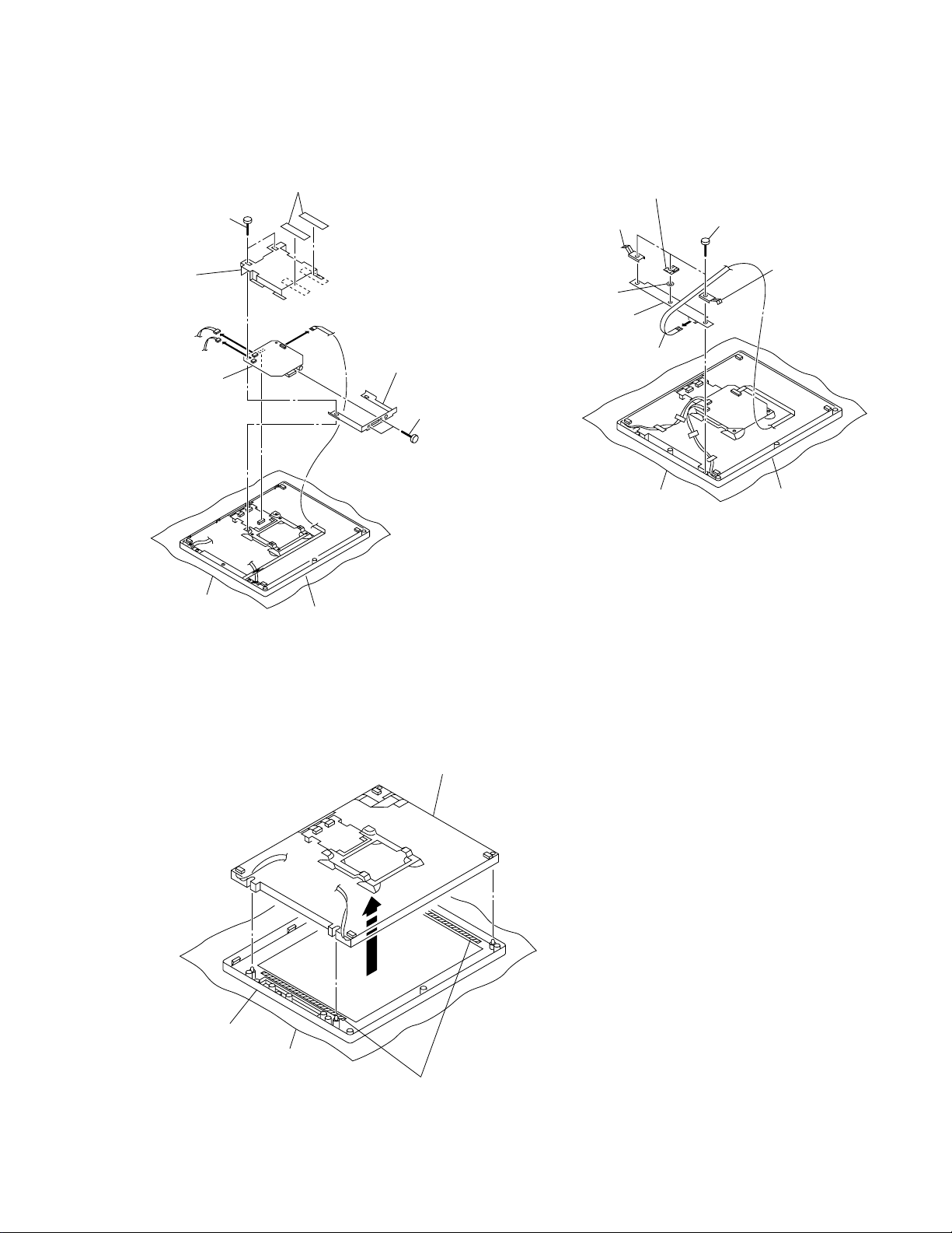
2-3. B BOARD REMOVAL
1 Two copper foil tapes
2 Two screws
3 Shield case
CN508
CN501
CN507
6 B board
5 Jack panel
4 Two screws
()
2-4. H BOARD REMOVAL
Pan head screw
M 1.6
3 Cover holder
2 Earth (H)
4 Washer (H)
5 H board
6 BH1 harness assembly
Cushion
1 Three screws
(+BVTP3x6)
2 Earth (H)
CN501
LCD module (TFT)
Cushion
LCD module (TFT)
2-5. LCD MODULE (TFT) REMOVAL
*Remove the B and H boards refering 2-3 and 2-4.
A
Front cover assembly
Cushion
1 Remove the LCD module (TFT) in the
derecition of allow A horizontally.
2 Panel tape
2-2
 Loading...