

Sony SDM-M81 User Manual
4-082-180-13(1)
TFT LCD Color
Computer Display
Operating Instructions
Mode d’emploi
Bedienungsanleitung
Manual de i nstrucciones
Istruzioni per l’uso
GB
FR
DE
ES
IT
SDM-M81
© 2000 Sony Corporation
Owner’s Record
The model and serial numbers are located at the rear of the unit.
Recordthese numbers inthespaces provided below. Referto them
whenever you call upon your dealer regarding this product.
Model No.
Serial No.
WARNING
Toprevent fire or shock hazard,do not expose the
unit to rain or moisture.
Dangerously high voltages are present inside the
unit. Do not open the c abinet. Refer servicing to
qualified personnel only.
FCC Notice
This equipment has been tested andfound to comply with the limits
for a Class B digital device, pursuant to Part 15 of the FCC Rules.
These limits are designed to provide reasonable protection aga inst
harmful interference in a residential installation. This equipment
generates, uses, and can radiate radiofrequency energy and,if not
installed and used in accordance with the instructions, may cause
harmfulinterference to radio communications.However, there isno
guarantee that interferencewill not occur in aparticular installation.
If this equipment does cause harmful interference to radio or
television reception, which can be determined by turning the
equipment off and on, the user is encouraged to try to correct the
interference by one or more of the following m easures:
– Reorient or relocate the receiving antenna.
– Increase the separation between the equipment and receiver.
– Connect the equipment into an outlet on a circuit different from
that to which the receiver is connected.
– Consultthe dealeror an experienced radio/TVtechnicianfor help.
You are cautioned that any changes or modifications notexpressly
approved in this manual could void your authority to operate t his
equipment.
INFORMATION
This product complies with Swedish National Council for M etrology
(MPR) standards issued in December 1990 (MPR II) for very low
frequency (VLF) and extremely low frequency (ELF).
INFORMATION
Ce produit est conforme aux normes du Swedish National Council
for Metrology de décembre 1990 (MPR II) en ce qui concerne les
fréquences très basses (VLF) et extrêmement basses (ELF).
INFORMACIÓN
Este producto cumple las normas del Consejo Nacional Sueco para
Metrología (MPR) emitidas en diciembre de 1990 (MPR II) para
frecuenciasmuy bajas (VLF) y frecuencias extremadamente bajas (ELF).
NOTICE
This notice is applicable for USA/Canada only.
If shipped to USA/Canada, install only a UL LIST ED/ C SA
LABELLED power supply cord meeting the f ollowing
specifications:
SPECIFICATIONS
Plug Type Nema-Plug 5-15p
Cord Type SVT or SJT, minimum 3 × 18 AWG
Length Maximum 15 feet
Rating Minimum 7 A, 125 V
NOTICE
Cette notice s’applique aux Etats-Unis et au Canada
uniquement.
Si cet appareil est exporté aux Etats-Unis ou auCanada, utiliser
le cordon d’alimentation portant la mention UL LISTED/CSA
LABELLED et remplissant les conditions suivantes:
SPECIFICATIONS
Type de fiche Fiche Nema 5-15 broches
Cordon Type SVT ou SJT, minimum 3 × 18 AWG
Longueur Maximum 15 pieds
Tension Minimum 7 A, 125 V
ENERGY STAR Partner, Sony
As an
Corporation has determined that this
product meets the
guidelines for energy efficiency.
This monitor complies with the
TCO’99 guidelines.
This monitor complies with the
TCO’95 guidelines.
NERGYSTAR
E
(for the white model)
If you have any questions about this product, you may call:
Sony Customer Information Center
1-800-222-SONY (7669)
or write to:
Sony Customer Information Center
1 Sony Drive, Mail Drop #T1-11, Park Ridge, NJ 07656
Declaration of Conformity
Trade Name: SONY
Model No.: SDM-M81
Responsible Party: Sony Electronics Inc.
Address: 680 Kinderkamack Road, Oradell,NJ 07649
USA
Telephone No.: 201-930-6972
This device complies with Part 15 of the FCC Rules. Operation is
subject to the following two conditions: (1) This device may not
cause harmful interference, and (2) this device must accept any
interference received, including interference that may cause
undesired operation.
2
(for the black model)

Table of Contents
Precautions............................................4
Identifyingpartsandcontrols..............................5
Setup..........................................7
Step 1: Connectthedisplaytoyourcomputer.................7
Step 2: Checkthedigital/analogselectswitch.................7
Step 3: Connect the audio cord . . . . . . . . . . . . ................8
Step 4: Connectthepowercord............................8
Step 5: Securethecordsandclosethebackcover.............8
Step 6: Turnonthemonitorandcomputer ...................9
Usingthestereospeakers................................9
Selectingtheinputsignal.................................9
Adjustingthetiltandheight...............................10
CustomizingYourMonitor.......................11
Navigatingthemenu....................................11
Adjustingthecontrast(CONTRAST).......................12
Adjusting the black level of an image (BRIGHTNESS). . . . . . . . . . 12
Eliminating flicker or blurring (PHASE/PITCH)
(AnalogRGBsignalonly)................................13
Adjusting the picture position (H CENTER/V CENTER)
(AnalogRGBsignalonly)................................13
Adjustingthecolortemperature(COLOR)...................14
Changing the picture size according to the signal (ZOOM) . . . . . . 15
Smoothingthepicture(SMOOTHING)......................15
Changing the menu’s position (MENU POSITION) . . . . . . . . . . . . 15
Additionalsettings......................................16
GB
• Macintosh is a trademark licensed to
Apple Computer, Inc., registered in the
U.S.A. and other countries.
• Windows
Microsoft Corporation in the United
States and other countries.
• IBM PC/AT and VGA are registered
trademarks of IBM Corporation of the
U.S.A.
• VESA and DDC
Video Electronics Standards
Association.
ENERGY STAR is a U.S. registered
•
mark.
• All other product names mentioned
herein may be the trademarks or
registeredtrademarksof theirrespective
companies.
•Furthermore,“”and“”arenot
mentionedineachcaseinthismanual.
is registered trademark of
are trademarks of the
TechnicalFeatures .............................17
Powersavingfunction...................................17
Automaticpicturequalityadjustmentfunction ................17
Troubleshooting................................18
On-screenmessages...................................18
Troublesymptomsandremedies..........................19
Self-diagnosis function . . . . . . ............................21
Specifications..................................21
Appendix.......................................i
Presetmodetimingtable ..................................i
TCO’99Eco-document(forthewhitemodel) .................ii
TCO’95Eco-document(fortheblackmodel)..........BackCover
3

Precautions
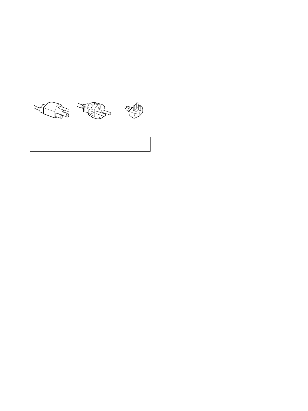
Warning on power connections
• Use the supplied power cord. If you use a different power cord,
be sure that it is compatible with your local power supply.
For the customers in the U.S.A.
If you do not use the appropriate cord, this monitor will not
conform to mandatory FCC standards.
For the customers in the UK
If you use the monitor in the UK, be sure to use the appropriate
UK power cord.
Example of plug types
for 100 t o 120 V AC for 200 to 240 V AC for 240 V AC only
For use only with AC adapter, SONY AC-V018
About the built-in stereo speakers
Be sure to keep magnetic recording equipment, tapes, and floppy
discs away from the speaker’s opening as the speakers generate a
magnetic field. This magnetic field may affect data stored on
magnetic tapes and discs.
Note on the LCD (Liquid Crystal Display)
Please note that the LCD screen is made with highprecision technology. However, black points or bright
points of light (red, blue, or green) may appear
constantly on the LCD screen, and irregular colored
stripes or brightness may appear on the LCD screen.
This is not malfunction.
(Effective dots: more than 99.99%)
Replacement of the fluorescent tube
A specially designed fluorescent tube is installed as the lighting
apparatus for this monitor. If the screen becomes dark, unstable,
or does not turn on, replace the fluorescent tube with a new one.
Consult your Sony dealer when replacing the fluorescent tube.
The equipment should be installed near an easily accessible outlet.
Installation
Do not install or leave the monitor:
• In places subject to extreme temperatures, for example near a
radiator, heating vent, or in direct sunlight. Subjecting the
monitor to extreme temperatures, such as in an automobile
parked in direct sunlight or near a heating vent, could cause
deformations of the casing or malfunctions.
• In places subject to mechanical vibration or shock.
• Near any equipment that generates a strong magnetic field,
such as a TV or various other householdappliances.
• In places subject to inordinate amounts of dust, dirt, or sand, for
example near an open window or an outdoor exit. If setting up
temporarily in an outdoor environment, be sure to take
adequate precautions against airborne dust and dirt. Otherwise
irreparable malfunctions could occur.
Handling the LCD screen
• Do not leave the LCD screen facing the sun as it can damage
theLCDscreen.Takecarewhenyouplacethemonitorbya
window.
• Do not push on or scratch the LCD screen. Do not place a heavy
object on the LCD screen. This may cause the screen to lose
uniformity or cause LCD panel malfunctions.
• If the monitor is used in a cold place, a residual image may
appear on the screen. This is not a malfunction. The screen
returns to normal as the temperature rises to a normal operating
level.
• If a still picture is displayed for a long time, a residual image
may appear for a while. The residual image will eventually
disappear.
• The LCD panel becomes warm during operation. This is not a
malfunction.
Maintenance
• Be sure to unplug the power cord from the power outlet before
cleaning your monitor.
• CleantheLCDscreenwithasoftcloth.Ifyouuseaglass
cleaning liquid, do not use any type of cleaner containing an
anti-static solution or similar additive as this may scratch the
LCD screen’s coating.
• Clean the cabinet, panel, and controls with a soft cloth lightly
moistened with a mild detergent solution. Do not use any type
of abrasive pad, scouring powder, or solvent, such as alcohol or
benzine.
• Do not rub, touch, or tap the surface of the screen with sharp or
abrasive items such as a ballpoint pen or screwdriver. This type
of contact may result in a scratched picture tube.
• Note that material deterioration or LCD screen coating
degradation may occur if the monitor is exposed to volatile
solvents such as insecticide, or if prolonged contact is
maintained with rubber or vinyl materials.
Transportation
• Disconnect all cables from the monitor and grasp the support
and base sections of the display stand firmly with both hands
whentransporting.If you drop the monitor,you may be injured
or the monitor may be damaged.
• When you transport this monitor for repair or shipment, use the
original carton and packing materials.
Disposal of the monitor
• Do not dispose of this monitor with general
household waste.
• The fluorescent tube used in this monitor contains
mercury.Disposal of thismonitor must becarried out
in accordance to the regulations of your local
sanitation authority.
4

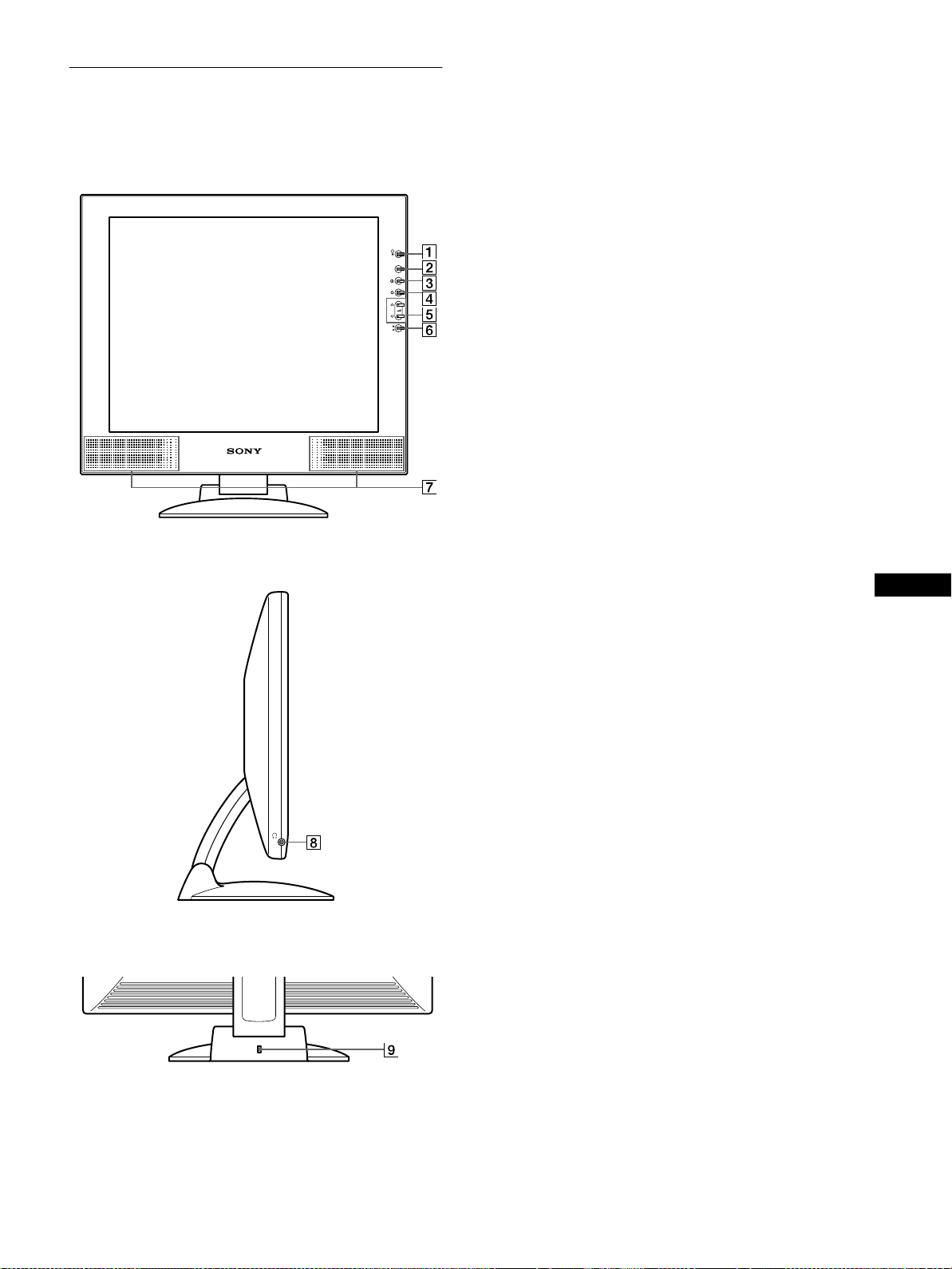
Identifying parts and controls
See the pages in parentheses for further details.
Front of the LCD display
Side view of the LCD display
1 1 (Power) switch and indicator (pages 9, 17, 21)
This switch turns the display on and off.
The power indicator lights up in green when the display is
turned on, and either flashes in green and orange, or lights up
in orange when the monitor is in power saving mode.
2 MENU button (pages 11, 12)
This button displays the main menu.
3 6 (contrast) button (page 12)
MENU
This button displays the CONTRAST menu.
4 8 (brightness) button (page 12)
INPUT
1
2
OK
This button displays the BRIGHTNESS menu.
5 2 (volume) +/– and M(+)/m(–) buttons (pages 9, 12)
These buttons display the VOLUME menu and function as
the M(+)/m(–) buttons when selecting the menu items and
making adjustments.
6 INPUT and OK button, and indicator (pages 9, 12)
This button selects the INPUT1 (DVI-I (digital/analog RGB)
connector) or INPUT2 (HD15 (analog RGB) connector)
video input signal. The input signal and corresponding input
indicator change each time you press this button.
This button also functions as the OK button when displaying
the menu on the screen.
GB
7 Stereo speakers (page 9)
This outputs the audio signals as sound.
Rear of the display stand
8 Headphones jack (page 9)
This jack outputs audio signals to the headphones.
9 Security Lock Hole
The security lock hole should be applied with the Kensington
Micro Saver Security System.
Micro Saver Sec urity System is a trademark of Kensington.
(continued)
5
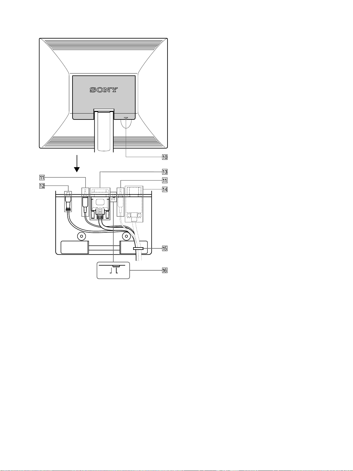
Rear of the LCD display
Open the back cover.
qf HD15 (analog RGB) input connector (INPUT2)
(page 7)
Thisconnectorinputs analogRGBvideosignals(0.700 Vp-p,
positive) and SYNC signals.
qg Cable holder (page 8)
This part secures cables and cords to the monitor.
qh Digital/analog select switch (page 7)
Whenconnectingthe DVI-I input connectorqd to a computer
equippedwith an HD15 (analogRGB)output connectorusing
the DVI-HD15 (analog RGB) video signal cable (supplied),
setthisswitchtoA– the right position.
When connecting it to a computer equipped with a DVI
(digital RGB) output connector using a DVI-DVI (digital
RGB) video signal cable (not supplied), set this switch to D –
the left position.
The switch is set to the right position (for analog RGB signal
input) as the default se tting.
D
A
DA
0 Back cover (page 8)
Openthiscoverwhen you connect/disconnect cables or cords.
qa AUDIO IN jacks (AUDIO1, AUDIO2) (page 8)
These jacks input audio signals when connected to the audio
output jack of the computer or other audio equipment.
qs DC IN connector (page 8)
This connectorprovides DC power to the display. Connect the
AC adapter to this connector.
qdDVI-I (digital/analog RGB) input connector (INPUT1)
(page 7)
Thisconnectorinputs analog RGB video signals(0.700Vp-p,
positive) with sync signals or digital RGB video signals that
comply with DVI Rev. 1.0. You can switch between digital
RGB signals and analog RGB signals with the digital/analog
select switch qh.
6
Setup
Before using your monitor, check that the following items are
included in your carton:
• LCD display
• Power cord
• AC adapter
• DVI-HD15 (analog RGB) video signal cable
• Audio cord (stereo miniplug)
• Cord strap
• Macintosh adapter
• Windows Monitor Information/Windows Utility/Macintosh
Utility Disk
• Warranty card
• Notes for Macintosh users
• This instruction manual
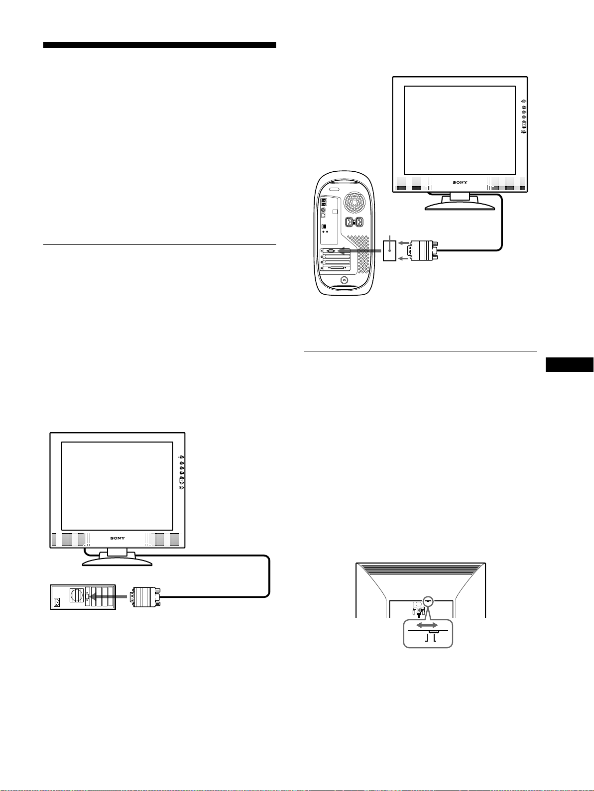
Connecting to a Macintosh
x
Use the supplied Macintosh adapter.
Macintosh adapter
(supplied)*
Step 1:Connect the display to your
computer
Turn off the monitor and computer before connecting.
If you connect the monitor to a computer equipped with a DVI
(digital RGB) output connector that complies with DVI Rev. 1.0,
use a DVI-DVI (digital RGB) video signal cable (not supplied).
Note
Do not touch the pins of the video signal cable connector as this might
bend the pins.
Connecting to an IBM PC/AT or compatible
x
computer
to video output
Macintosh
* Refer to the supplied “Notes for Macintosh users” for further details.
DVI-HD15 (analog RGB)
video signal cable
(supplied)
Step 2:Check the digital/analog
select switch
Before turning on the monitor,be sure to check the switch setting.
When connecting the DVI-I input connector on the monitor to a
computer equippedwith an HD15(analog RGB) output connector
usingtheDVI-HD15(analogRGB) video signal cable (supplied),
set the switch to A – the right position.
When connecting it to a computer equipped with a DVI (digital
RGB) output connector using a DVI-DVI (digital RGB) video
signal cable (not supplied), set the switch to D – the left position.
The switch is set to the right position (for analog RGB signal
input) as the default setting.
GB
IBM PC/AT or
compatible computer
to video output
DVI-HD15(analogRGB)video
signal cable (supplied)
DA
(continued)
7
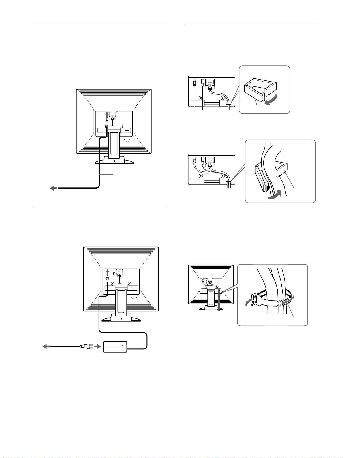
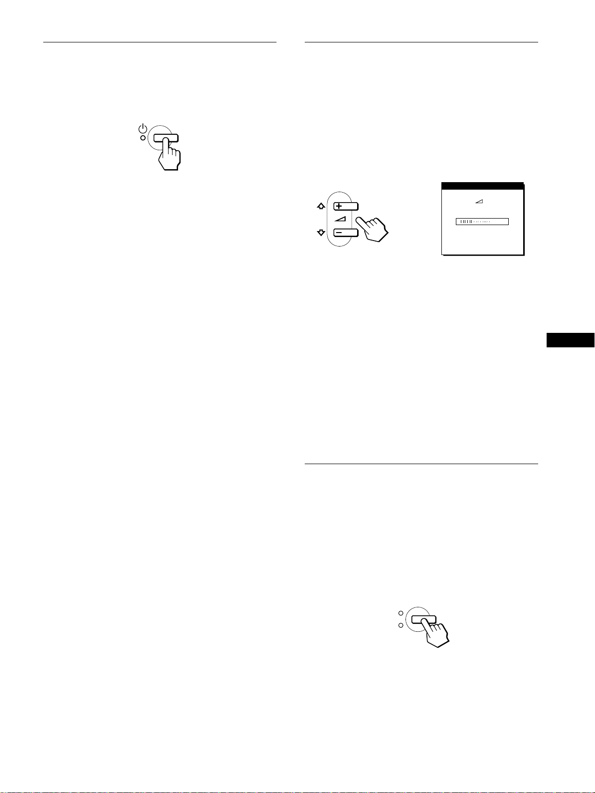
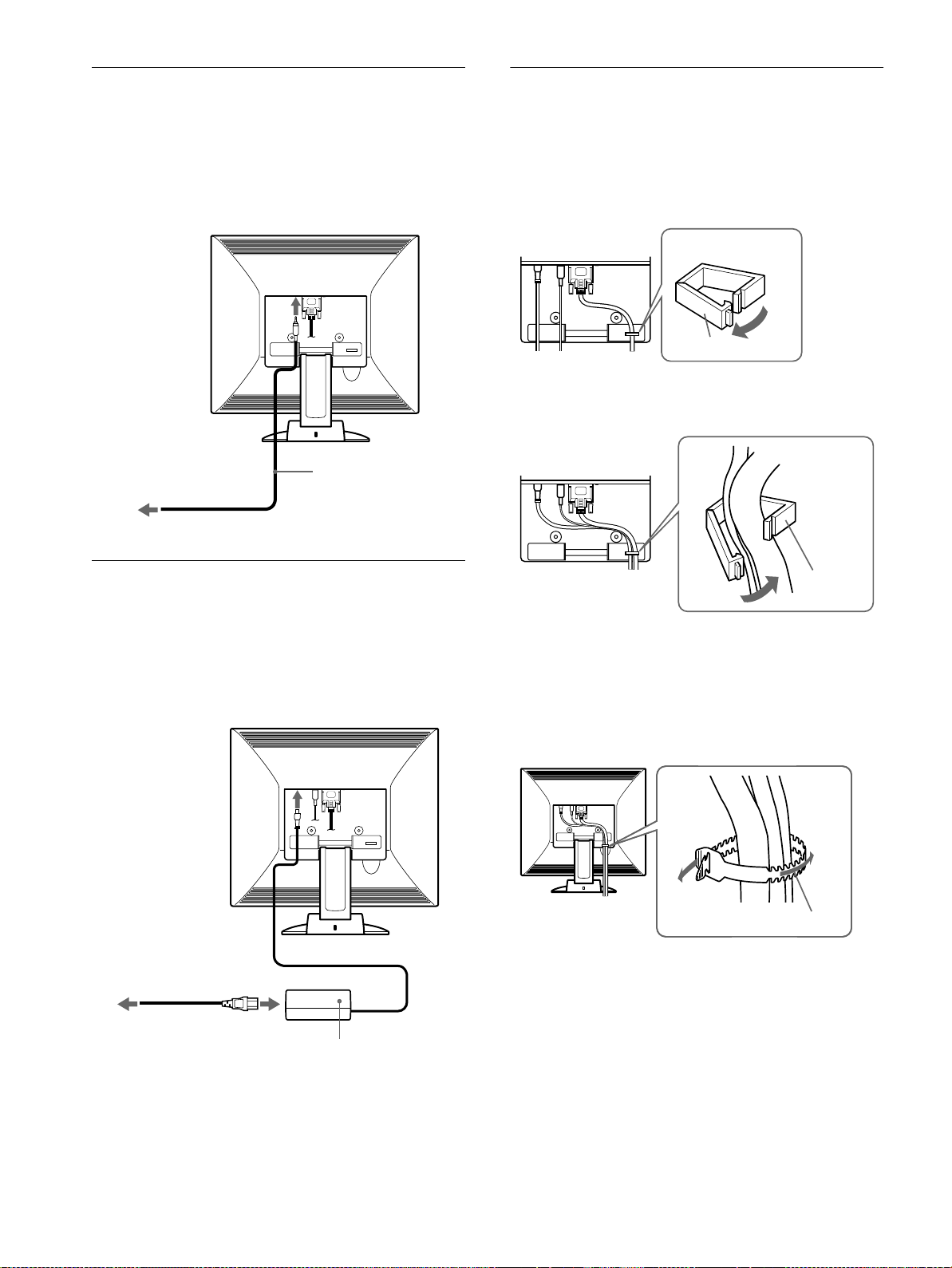
Step 3:Connect the audio cord
Step 5:Secure the cords and close
Openthe back cover andturn off the displayand computerbefore
connecting.
Note
Do not open the back cover more than 90 degrees, otherwise damage may
result to the back cover or latch.
to audio input
to audio output of the
computer or other audio
equipment
audio cord (supplied)
the back cover
1
Remove the cable holder.
Cable holder
2
Secure the cables and cords with the cable holder.
Cable
holder
Step 4:Connect the power cord
Withthe monitor andcomputer switched off, first connect the AC
adapter and power cord to the monitor, then connect it to a power
outlet.
to DC IN
to a power outlet
power cord (supplied)
AC adapter (supplied)
3
Close the back cover.
Bundle the cables and cords
You can bundle the cables and cords by using the supplied cord
strap.
Cord strap
8
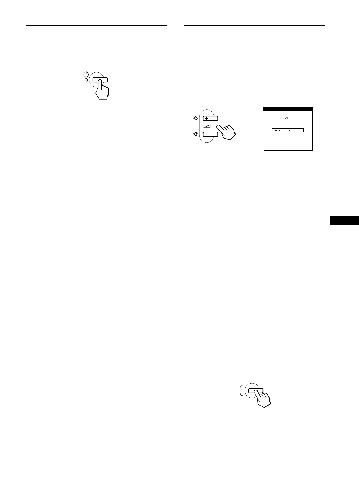
Step 6:Turn on the monitor and
Using the stereo speakers
computer
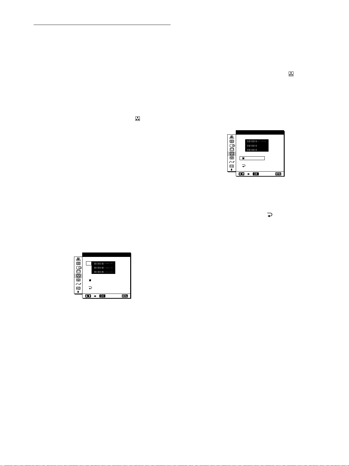
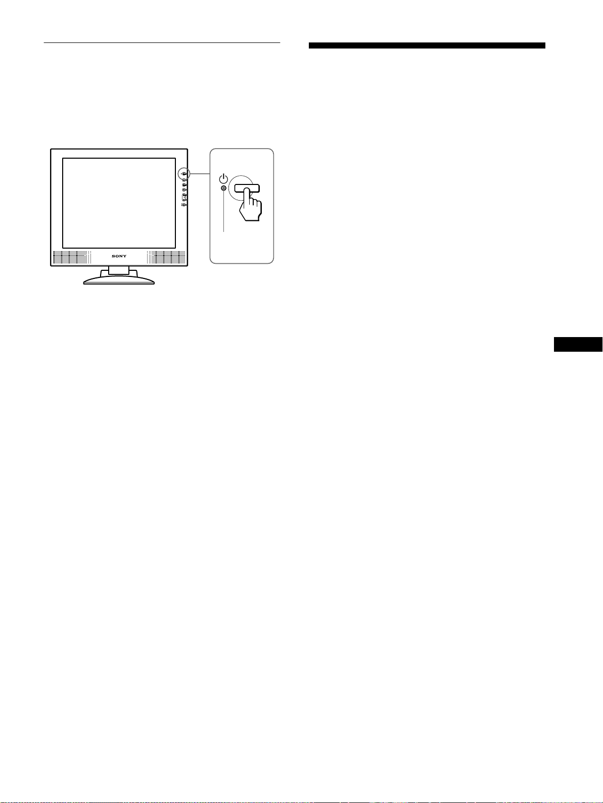
Press the 1 (power) switch.
1
The indicator of the monitor lights up in green.
Turn on the computer.
2
The installation of your monitor is complete. If necessary, use the
monitor’s controls to adjust the picture.
If no picture appears on your screen
• Check that the monitor is correctly connected to the computer.
• If NO INPUT SIGNAL appears on the screen:
– The computer is in the power saving mode. Try pressing any
key on the keyboard or moving the mouse.
– Check that the input signal setting is correct.
– Check that the digital/analog select switch setting is correct.
• If CABLE DISCONNECTED appears on the screen:
– Check that the video signal cable is properly connected.
– Check that the input signal setting is correct.
• If OUT OF SCAN RANGE appears on the screen, reconnect
the old monitor. Then adjust the computer’sgraphicsboardso
that the horizontal frequency is between 28 – 92 kHz, and the
vertical frequency is between 48 – 85 Hz.
For more information about on-screen messages, see “Trouble
symptoms and remedies” on page 19.
No need for specific drivers
The monitor complies with the “DDC” Plug & Play standard and
automatically detects all the monitor’s information. No specific driver
needs to be installedto the computer.
The firsttimeyou turnon y our computer after connectingthemonitor,the
setup Wizard may appear on the screen. In this case, follow the on-screen
instructions.The Plug & Play monitor is automatically selected so that
you can use this monitor.
You can listen to music, sound, and other audio files using the
stereo speakers of your monitor.
Adjusting the volume
Volume adjustments are made using a separate VOLUME menu
from the main menu (page 11).
Press the 2 +/– buttons.
1
The VOLUME menu appears on the screen.
VOL UME
40
Press the 2 +/– buttons to adjust the volume.
2
The menu automatically disappears after about 5 seconds.
Using the headphones jack
You can listen to the audio signals from your computer or other
audio equipment using headphones. Connect your headphones to
the headphones jack. The speakers turn off when headphones are
connected to the headphones jack. Adjust the volume of the
headphones using the VOLUME menu.
Notes
• You cannot adjust the volume when displaying the main menu on the
screen.
• When your monitor is in power saving mode, no sound comes from the
speakers or the headphones.
Selecting the input signal
Youcanconnecttwo computers to this monitor using theINPUT1
and INPUT2 connectors. To select one of the two computers, use
the INPUT button.
GB
The vertical frequency turns to 60 Hz.
Since flickers are unobtrusive on the monitor, you can use it as it is. You
do not need to set the vertical frequency to any particularhigh value.
If your computer or graphics board has difficulty communicating with this
monitor, install the information file for this monitor using the Windows
Monitor Information Disk. For details on installing, refer to the ReadMe
file on the disk.
Press the INPUT button.
The input signal and correspondinginput indicator change each
time you press this button.
• 1: Input via the DVI-I (digital/analog RGB) input connector
• 2: Input via the HD15 (analog RGB) input connector
INPUT
1
2
OK
Note
You cannot select the input signal when displaying the main menu on the
screen.
9

Adjusting the tilt and height
This display can be adjusted within the angles shown below.
70°
30°
40°
60°
45°
45°
2
Grasp the lower sides of the LCD panel, then adjust
screen tilt.
3
Grasp the lower sides of the LCD panel, then adjust
screen height.
To adjust the angles, follow the procedure of the steps below.
1
Grasp the lower middle part of the display while
holding the display stand, then, tilt the LCD panel
adequately backward.
Note
When adjusting the screen tilt and height, proceed slowly and carefully,
being sure not to hit the LCD panel against the desk or the base of the
display stand.
To use the display comfortably
This display is designed so that you can set it up at a comfortable
viewing angle. Adjust the viewing angle of your display
according to the height of the desk and chair, and so that light is
not reflected from the screen to your eyes.
10

Customizing Your Monitor
Before making adjustments
Connect the monitor and the computer, and turn them on.
Wait for at least 30 minutes before making adjustments for the
best results.
4 V CENTER (Analog RGB
signal only) (page 13)
Select the V CENTER menu
toadjustthe picture’s vertical
centering.
VCENTER
50
EX I T
You can make numerous adjustments to your monitor using the
on-screen menu.
Navigating the menu
Pressthe MENU buttonto display the main menu on your screen.
For more information on using the MENU button, see “Using the
MENU, M(+)/m(–), and O K buttons” on page 12 .
PHASE
MENU
Use the M(+)/m(–) and OK buttons to select one of the following
menus. For more information on using the M(+)/m(–)andOK
buttons, see “Using the MENU, M(+)/m(–), and OK buttons” on
page 12.
1 PHASE (Analog RGB
signal only) (page 13)
Select the PHASE menu to
adjust the phase when the
characters or pictures appear
fuzzy throughout the entire
screen. Adjust thephase after
adjusting the pitch.
2 PITCH (Analog RGB
signal only) (page 13)
Select the PITCH menu to
adjust the pitch when the
characters or pictures are
unclear in some areas of the
screen.
3 H CENTER (Analog RGB
signal only) (page 13)
Select the H CENTER menu
to adjust the picture’s
horizontal centering.
,
PHASE
30
EX I T
PITCH
1688
EX I T
HCENTER
50
5 COLOR (page 14)
Select the COLOR menu to
adjust the color temperature
of the picture. This adjusts
thetoneofthescreen.
6 ZOOM (page 15)
Select the ZOOM menu to
adjust the picture’ssize
accordingtotheinput
signal’s aspect ratio or
resolution.
7 SMOOTHING (page 15)
Select the SMOOTHING
menu to adjust the picture’s
sharpness according to the
type of an object displayed
on the screen.
8 MENU POSITION
(page 15)
Select the MENU
POSITION menu to change
the on-screen menu position.
9 Other menus (page 16)
Select the m to adjust other
settings listed below.
• RESET
• AUDIO SELECT
• BACKLIGHT
• POWER SAVE
• LANGUAGE
• MENU LOCK
COLOR
ZOOM
SMOOT H I NG
MEN NUP
0
9300K
650
5000K
USER
ADJ U ST
FULL 2
FULL 1
REAL
TEXT
STA
GRAPH
RESET
S CREEN
ALL
0K
ND
ARD
ICS
OS I I OT
RESET
EX I T
EX I T
GB
EX I T
EX I T
RESET
EX I T
EX I T
11

Using the MENU,M(+)/m(–), and OK buttons
x
1
Display the main menu.
Press the MENU button to display the main menu on your
screen.
MENU
2
Select the menu you want to adjust.
Press the M(+)/m(–) buttons to display the desired menu.
Press the OK button to select the menu item.
INPUT
1
3
Adjust the menu.
,
2
OK
Press the M(+)/m(–) buttons to make the adjustment, then
press the OK button.
When you press the OK button, the setting is stored, then the
display returns to the previous menu.
Adjusting the contrast (CONTRAST)
Contrast adjustment is made using a separate CONTRAST menu,
different from the main menu (page 11).
1
Press the 6 (contrast) button.
The CONTRAST menu appears on the screen.
CONTRAST
70
64.0kHz/ 60Hz
Horizontal frequency
of the current input
signal
Displaying the current input signal
The horizontal and vertical frequencies of the current input signal are
displayed in the CONTRAST and BRIGHTNESS menus.
2
Press the M(+)/m(–) buttons to adjust the contrast.
Vertical frequency of
the current input
signal
The menu automatically disappears after about 5 seconds.
Adjusting the black level of an
image (BRIGHTNESS)
INPUT
1
2
OK
4
Close the menu.
,
Press the MENU button once to return to normal viewing. If
no buttons are pressed, the menu closes automatically after
about 30 seconds.
MENU
Resetting the adjustments
x
You can reset the adjustments using the RESET menu. For more
information on resetting the adjustments, see “Resetting the
adjustments (RESET)” on page 16.
Brightness adjustment is made using a separate BRIGHTNESS
menu, different from the main menu (page 11).
1
Press the 8 (brightness) button.
The BRIGHTNESS menu appears on the screen.
B NESSRIGHT
50
64.0kHz/ 60Hz
Horizontal frequency
of the current input
signal
2
Press the M(+)/m(–) buttons to adjust the
Vertical frequency of
the current input
signal
brightness.
The menu automatically disappears after about 5 seconds.
If the screen is too bright
Adjust the backlight. For more information about adjusting the
backlight, see “Adjusting the backlight” on page 16.
Note
You can adjust neither contrast nor brightness when displaying the main
menu on the screen.
12

Eliminating flicker or blurring
(PHASE/PITCH) (Analog RGB
Press the M(+)/m(–) buttons to select (PHASE)
8
and press the OK button.
The PHASE menu appears on the screen.
signal only)
When the monitor receives an input signal, the automatic picture
quality adjustment function of this monitor a utomatically adjusts
the picture position, phase, and pitch, and ensures that a clear
picture appears on the screen. For more information about this
function,see “Automatic picture quality adjustment function” on
page 17.
For some input signals, this function may not completely adjust
the picture position, phase, and pitch. In this case, you can
manually set these adjustments according the following
instructions. If you manually set these adjustments, they are
stored in memory and automatically recalled whenever the
monitor receives the same input signals.
Thesesettingsmayhavetoberepeatedifyouchangetheinput
signal after reconnecting your computer.
Set the resolution to 1280 × 1024 on the computer.
1
Load the Utility Disk.
2
Start the Utility Disk and display the test pattern.
3
For Windows
[Windows]/[Win Utility.exe].
Click [Utility]
For Macintosh
Click [Utility]t[Mac]/[Mac Utility].
Press the MENU button.
4
The main menu appears on the screen.
Press the M(+)/m(–) buttons to select (PITCH)
5
and press the OK button.
The PITCH menu appears on the screen.
Press the M(+)/m(–) buttons until the vertical stripes
6
disappear.
Adjust so that the vertical stripes disappear.
t
Press the M(+)/m(–) buttons until the horizontal
9
stripes are at a minimum.
Adjust so that the horizontal stripes are at a minimum.
,
Click [END] on the screen to turn off the test pattern.
10
To reset the automatic picture qua lity adjustment
Select SCREEN RESET and activate it using the RE SET menu. For more
information on using the RESET menu, see “Resetting the adjustments
(RESET)” on page 16.
Note
When using digital RGB signals, you do not need to set the PHASE or
PITCH.
Adjusting the picture position
(H CENTER/V CENTER) (Analog
RGB signal only)
If the picture is not in the center of the screen, adjust the picture’s
centering as follows.
These settings may have to be repeated if you change the input
signal after reconnecting your computer.
Start the Utility Disk and display the test pattern.
1
Repeat steps 2 and 3 of “Eliminating flicker or blurring
(PHASE/PITCH) (Analog RGB signal only).”
Press the MENU button.
2
The main menu appears on the screen.
GB
,
Press the OK button.
7
The main menu appears on the screen.
If horizontal stripes are observed over the entire screen, adjust
the phase as the next step.
Press the M(+)/m(–) buttons to select (H
3
CENTER) or (V CENTER) and press the OK
button.
The H CENTER or V CENTER menu appears on the screen.
Move the picture up, down, left, or right until the
4
frame at the perimeter of the test pattern
disappears.
Press the M(+)/m(–) buttons to adjust the picture’s
centering using the H CENTER menu for horizontal
adjustment, or the V CENTER menu for vertical
adjustment.
Click [END] on the screen to turn off the test pattern.
5
Note
When using digital RGB signals, you do not need to set the H CENTER
or V CENTER.
13
Adjusting the color temperature
(COLOR)
To c hange the GAMMA setting
You can select the GAMMA setting from “GAMMA 1”–
“GAMMA 3.” The highest setting is “GAMMA 3.”
The COLOR settings allow you to adjust the picture’s color
temperature by changing the color level of the white color field.
Colors appear reddish if the temperature is low, and bluish if the
temperature is high.
You can set the color temperature to 9300K, 6500K, 5000K or
user adjustment.
1
Press the MENU button.
The main menu appears on the screen.
2
Press the M(+)/m(–) buttons to select (COLOR)
and press the OK button.
The COLOR menu appears on the screen.
3
Press the M(+)/m(–) buttons to select the desired
color temperature and press the OK button.
Thepresetcolortemperaturesare 9300K, 6500K, and 5000K.
Since the default setting is 9300K, the whites will change
from a bluish hue to a reddish hue as the temperature is
loweredto6500Kand5000K.
4
If necessary, fine tune the color temperature.
Firstpress the M(+)/m(–)buttons to select ADJUST and press
the OK button. Then press the M(+)/m(–) buttons to select R
(Red) or B (Blue) and press the OK button. Then press the
M(+)/m(–) buttons to a djust the color temperature and press
the OK button. Since this adjustment changes the color
temperature by increasing or decreasing the R and B
components with respect to G (green), the G component is
fixed.
1
Press the MENU button.
The main menu appears on the screen.
2
Press the M(+)/m(–) buttons to select (COLOR)
and press the OK button.
The COLOR menu appears on the screen.
3
Change the GAMMA setting.
First press the M(+)/m(–)buttons to select ADJUSTand press
the OK button. Then press the M(+)/m(–) buttons to select
GAMMA 1 to GAMMA 3 and press the OK button.
USER AD J UST TMEN
R50
G50
B
GAMMA 1
GAMMA 2
GAMMA 3
50
EX I T
If you change the GAMMA setting, the new setting is
automatically recalled whenever USER is selected.
To return to the main menu
Press the M(+)/m(–) buttons to select , then press the OK
button.
USER AD J UST TMEN
R50
G50
B
GAMMA 1
GAMMA 2
GAMMA 3
50
EX I T
If you fine tune the color temperature,the newcolor setting is
stored in memory for USER ADJUSTMENT and
automatically recalled whenever USER is selected.
The USER ADJUSTMENT se tting is common to both the
input signals. If you change the user adjustment setting for
one input signal, the setting for the other input signal is also
changed.
14

Changing the picture size
Changing the menu’sposition
according to the signal (ZOOM)
The monitor is set to display the picture on the screen in full,
irrespective of the picture’s mode or resolution in the default
setting. You can also view the picture at its actual aspect ratio or
resolution.
Press the MENU button.
1
The main menu appears on the screen.
Pressthe M(+)/m(–) buttonsto select (ZOOM) and
2
press the OK button.
The ZOOM menu appears on the screen.
Press the M(+)/m(–) buttons to select the desired
3
mode.
1280 × 1024 resolution signals fill the entire screen and
ZOOM is not possible regardless of these settings.
• FULL2: The input signal is displayed on the screen in full,
irrespective of the picture’s mode or resolution.
• FULL1: The input signal is displayed on the screen at its
actual aspect ratio. Therefore, black bands may appear at
the top and bottom of the picture depending on the signal.
• REAL: The input signal is displayed on the screen at its
actual resolution. Sub-SXGA signals are displayed at the
center of the screen surrounded by a black frame.
(MENU POSITION)
You can change the menu position if it is blocking an image on
the screen.
Press the MENU button.
1
The main menu appears on the screen.
Press the M(+)/m(–) buttons to select (MENU
2
POSITION) and press the OK button.
The MENU POSITION menu appears on the screen.
Press the M(+)/m(–) buttons to select the desired
3
position.
There are threepositions each for the top of the screen and the
bottom of the screen, and one for the screen center.
GB
To restore the default setting (displayed on the screen in full)
Select “FULL2” in step 3.
Smoothing the picture
(SMOOTHING)
If the picture displayed at the FULL2 or FULL1 mode of ZOOM
is not smooth, use the picture smoothing function. Note that 1280
× 1024 resolution signals are shown only in REAL mode and
SMOOTHING is not possible.
Press the MENU button.
1
The main menu appears on the screen.
Press the M(+)/m(–) buttons to select
2
(SMOOTHING), and press the OK button.
The SMOOTHING menu appears on the screen.
Press the M(+)/m(–) buttons to select the desired
3
mode.
The smoothingeffect becomes stronger in the order of
TEXTtSTANDARDtGRAPHICS.
• TEXT: To make the characters appear clear. (This mode is
suited for text-based applications.)
• STANDARD: Standard smoothing effect (factory preset
smoothing effect)
• GRAPHICS: To make the pictures appear clean. (This
mode is suited for CD-ROM software such as photo
images or illustrations.)
Note
When you set the ZOOM menu to REAL, the SMOOTHING menu is not
available.
15

Additional settings
You can adjust the following menus:
• RESET
• AUDIO SELECT
• BACKLIGHT
• POWER SAVE
• LANGUAGE
• MENU LOCK
1
Press the MENU button.
The main menu appears on the screen.
2
Press the M(+)/m(–) buttons to select m.
Other menu icons appear on the menu screen.
3
Press the M(+)/m(–) buttons to select the desired
menu and press the OK button.
Adjust the selected menu ac cording to the following
instructions.
Resetting the adjustments (RESET)
x
First press the M(+)/m(–) buttons to select 0 (RESET)
and press the OK button. Then press the M(+)/m(–)
buttons to select the desired mode.
• SCREEN RESET: The automatic picture quality adjustment
function of this monitor automatically adjusts the picture
position, phase and pitch, to the most appropriate value (for
analog RGB signal only).
• ALL RESET: To reset all of the adjustment data to the default
setting. The setting of the LANGUAGE menu is retained.
• : To cancel resetting and return to the menu screen.
Setting the audio input
x
This monitor is equipped with two audio input jacks. The
effective audio input switches depending on this menu setting.
First press the M(+)/m(–) buttons to select (AUDIO
SELECT) and press the OK button. Then press the M(+)/
m(–) buttons to select the desired mode.
• AUTO: To select either audio input by switching with the
INPUT button.
• INPUT1: To select audio input via the AUDIO1 jack.
• INPUT2: To select audio input via the AUDIO2 jack.
Setting up the power saving mode
x
This monitor has a function which enables it to enter the power
saving mode automatically according to the power saving settings
of the computer. You can prevent the monitor from entering the
power saving mode by setting the following option to OFF.
For more information of the power saving mode, see page 17.
First press the M(+)/m(–) buttons to select (POWER
SAVE) and press the OK button. Then press the
M(+)/m(–) buttons to select either ON or OFF.
Selecting the on-screen menu l anguage
x
English, German, French, Spanish, Italian and Japanese versions
of the on-screen menus are available. The default setting is
English.
First press the M(+)/m(–) buttons to select
(LANGUAGE) and press the OK button. Then press
the M(+)/m(–) buttons to select a language.
• ENGLISH
• DEUTSCH:German
• FRANÇAIS:French
• ESPAÑOL:Spanish
• ITALIANO: Italian
• : Japanese
Locking the menus and controls
x
First press the M(+)/m(–) buttons to select (MENU
LOCK) and press the OK button. Then press the M(+)/
m(–) buttons and select ON.
Only the 1 (power) switch and (MENU LOCK) will
operate. If any other items are selected, the mark appears on
the screen.
To cancel the menu lock
Repeat the procedure above and set (MENU LOCK) to OFF.
ZZ...
Note
When you set this menu to INPUT1 or INPUT2, the audio input does not
switch even if the video input is switched with the INPUT button. If you
want to link the audio input to switching with the INPUT button, set the
menu to AUTO.
Adjusting the backlight
x
If the screen is too bright, adjust the backlight.
First press the M(+)/m(–) buttons to select
(BACKLIGHT) and press the OK button. Thenpress
the M(+)/m(–) buttons to adjust the desired light level.
16

Technical Features
Automatic picture quality
adjustment function
Power saving function
This monitor meets the power-saving guidelines set by VESA,
NERGYSTAR, and NUTEK. If the monitor is connected to a
E
computer or video graphics board that is DPMS (Display Power
Management Signaling) compliant, the monitor will automatically
reduce power consumption as shown below.
Power mode Power consumption1(power)
normal
operation
active off*
(deep sleep)**
power off 3 W (max.) off
* Whenyour computer enters the “active off” mode, the input signal is
cut and NO INPUT SIGNAL appears on the screen. After 20 seconds,
the monitor enters the power saving mode.
** “Deep sleep” is a power saving mode defined by the Environmental
Protection Agency.
50 W (max.) green
3 W (max.) orange /
indicator
green and orange
alternate
When the monitor receives an input signal, it automatically
matches the signal to one of the factory preset modes stored in the
monitor’s memory to provide a high quality picture at the center
of the screen. (See the Appendix for a list of the factory preset
modes.)
For input signals that do not match one of the factory preset
modes, the automatic picture quality adjustment function of this
monitor automatically adjusts the picture position, phase, and
pitch, and ensures that a clear picture appears on the screen for
any timing within the monitor’s frequency range (horizontal: 28 –
92 kHz, vertical: 48 – 85 Hz).
Consequently, the first time the monitor receives input signals
that do not match one of the factory preset modes, the monitor
may take a longer time than normal for displaying the picture on
the screen. This adjustment data is automatically stored in
memory so that next time, the monitor will function in the same
way as when the monitor receives the signals that match one of
the factory preset modes.
In all modes mentioned above, if the picture is adjusted, the
adjustment data is stored as a user mode and automatically
recalled whenever the same input signal is received.
Note
While the automatic picture quality adjustment function is activated, only
1
the
(power) switch will operate.
GB
17
Troubleshooting
Before contacting technical support, refer to this section.
On-screen messages
If there is something wrong with the input signal, one of the
followingmessages appears on the screen. To solve the problem,
see “Trouble symptoms and remedies” on page 19.
If CABLE DISCONNECTED appears on the screen
This indicates that the video signal cable has been disconnected
from the currently selected connector.
INFORMATION
CAB L E D I SCONNECTED
INPUT:1
GO TO POWER SAVE
If OUT OF SCAN RANGE appears on the screen
This indicates that the input signal is not supported by the
monitor’s specifications. Check the following items.
INFORMATION
OUT OF SCAN RANGE
x x . x kHz / x xHz
If “xx.x kHz/xx Hz” is displayed
This indicates that either the horizontal or vertical frequency
is not supported by the monitor’sspecifications.
The figures indicate the horizontal and vertical frequencies of
the current input signal. The horizontal frequencies above
100 kHz and the vertical frequencies above 100 Hz are
representedby99.9kHzand99Hz,respectively.
If “RESOLUTION > SXGA” is displayed
This indicates that the resolution is not supported by the
monitor’s specifications.
If NO INPUT SIGNAL appears on the screen
This indicates that no signal is being input via the currently
selected connector.
GO TO POWER SAVE
The monitor will enter the power saving mode after about 5
seconds from the time the message is displayed.
INFORMATION
NO INPUT S IGNA L
INPU T : 1
GO TO POWER SAVE
GO TO POWER SAVE
The monitor will enter the power saving mode after about 5
seconds from the time the message is displayed.
18

Trouble symptoms and remedies
If a problem is caused by the connected computer or other equipment, please refer to the connected equipment’s instruction manual.
Use the self-diagnosis function (page 21) if the following recommendations do not resolve the problem.
Symptom Check these items
No picture
If the 1 (power) indicator is not lit,
or if the 1 (power) indicator will not
light up when the 1 (power) switch
is pressed
If the 1 (power) indicator is green
or flashingorange
If CABLE DISCONNECTED
appears on the screen
If NO INPUT SIGNAL appears on
the screen, or the 1 (power)
indicator is either orange or
alternating between green and
orange
• Check that the power cord is properly connected.
• Check that the monitor’spoweris“on” (page 9).
• Use the self-diagnosis function (page 21).
• Check that the video signal cable is properly connected and all plugs are firmly seated in
their sockets (page 7).
• Check that the video input connector’s pins are not bent or pushed in.
• Check that the input select setting is correct (page 9).
• A non-supplied video signal cable is connected. If you connect a non-supplied video
signal cable, CABLE DISCONNECTED may appear on the screen before entering the
power saving mode. This is not a malfunction.
• Check that the video signal cable is properly connected and all plugs are firmly seated in
their sockets (page 7).
• Check that the video input connector’s pins are not bent or pushed in.
• Check that the input select setting is correct (page 9).
• Set the digital/analog select switch to an appropriate position according to the type of
signals input via the DVI-I (digital/analog RGB) input connector (page 7).
GB
xProblems caused by the connected computer or other equipment
• The computer is in the power saving mode. Try pressing any key on the keyboard or
moving the mouse.
• Check that your graphics board is attached to the computer properly.
• Check that the computer’spoweris“on.”
If OUT OF SCAN RANGE appears
on the screen
If using Windows • If you replaced an old monitor with this monitor, reconnect the old monitor and do the
If using a Macintosh system • Check and refer to the supplied “Notes for Macintosh users.”
Picture flickers, bounces,
oscillates, or is scrambled
xProblems caused by the connected computer or other equipment
• Check that the video frequency range is within that specified for the monitor. If you
replaced an old monitor with this monitor, reconnect the old monitor and adjust the
frequency range to the following:
Horizontal frequency: 28 – 92 kHz, Vertical frequency: 48 – 85 Hz
following. Select “SONY” from the “Manufactures” list and select “SDM-M81” from the
“Models” list in the Windows device selection screen. If “SDM-M81” does not appear in
the “Models” list, try “Plug & Play” or install the information file for this monitor using
the Windows Monitor Information Disk (page 9).
• Adjust the pitch and phase (Analog RGB signal only) (page 13).
• Isolate and eliminate any potential sources of electric or magnetic fields such as other
monitors, laser printers, electric fans, fluorescent lighting, or televisions.
• Move the monitor away from power lines or place a magnetic shield near the monitor.
• Try plugging the monitor into a different AC outlet, preferably on a different circuit.
• Change the orientation of the display.
xProblems caused by the connected computer or other equipment
• Check your graphics board manual for the proper monitor setting.
• Confirm that the graphics mode (VESA, Macintosh 19'' Color,etc.) and the frequency of
the input signal are supported by this monitor (Appendix). Even if the frequency is within
the proper range, some graphics boards may have a sync pulse that is too narrow for the
monitor to sync correctly.
• Adjust the computer’s refresh rate (vertical frequency) to obtain the best possible picture.
19
Symptom Check these items
Pictureisfuzzy • Adjust the brightness and contrast (page 12).
• Adjust the pitch and phase (Analog RGB signal only) (page 13).
xProblems caused by the connected computer or other equipment
• Set the resolution to SXGA (1280 × 1024) on your computer.
Pictureisghosting • Eliminate the use of video cable extensions and/or video switch boxes.
• Check that all plugs are firmly seated in their sockets.
Picture is not centered or sized
properly
• Adjust the pitch and phase (Analog RGB signal only) (page 13).
• Adjust the picture position (Analog RGB signal only) (page 13). Note that some video
modes d o not fill the screen to the edges.
Pictureistoosmall • Set the zoom setting to FULL2 (page 15).
xProblems caused by the connected computer or other equipment
• Set the computer’sresolutiontothescreen’s resolution.
Pictureisdark • Adjust the brightness (page 12).
• Adjust the backlight (page 16).
• It takes a few minutes for the display to become bright after turning on the monitor.
Wavy or elliptical pattern (moire)
• Adjust the pitch and phase (Analog RGB signal only) (page 13).
is visible
Color is not uniform • Adjust the pitch and phase (Analog RGB signal only) (page 13).
White does not look white • Adjust the color temperature (page 14).
Monitor buttons do not operate
• IfthemenulockissettoON,setittoOFF(page16).
( appears on the screen)
The monitor turns off after a while • SetthepowersavingfunctiontoOFF(page16).
xProblems caused by the connected computer or other equipment
• Set the computer’s power saving setting to off.
Displaying this monitor’s name, serial number,
and date of manufacture.
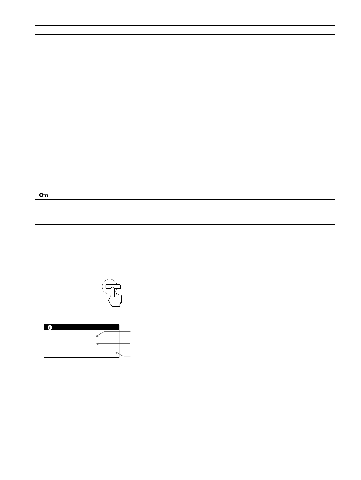
While the monitor is receivinga videosignal, press and
hold the MENU button for more than 5 seconds.
The monitor’s information box appears.
MENU
Example
INFORMATION
MODEL : SDM-M81
SER NO : 1234567
MANUFACTURED : 2001-40
Model name
Serial number
Week and year
of manufacture
If any problem persists, call your authorized Sony dealer and give
the following information:
• Model name: SDM-M81
• Serial number
• Name and specifications of your computer and graphics board.
• Type of input signals (analog RGB/digital RGB)
20
Self-diagnosis function
Thismonitoris equipped with aself-diagnosisfunction.If there is
a problem with your monitor or computer(s), the screen will go
blank and the 1 (power) indicator will either light up green or
flash orange. If the 1 (power) indicator is lit in orange, the
computer is in power saving mode. Try pressing any key on the
keyboard or moving the mouse.
1 (power)
indicator
If the 1 (power) indicator is green
Turn off the 1 (POWER) switch and disconnect the
1
video signal cables from the monitor.
Turn the monitor on by pressing the 1 (POWER)
2
switch.
If all four color bars appear (white, red, green, blue), the monitor
is working properly. Reconnect the video input cables and check
the condition of your computer(s).
If the color bars do not appear, there is a potentialmonitor failure.
Inform your authorized Sony dealer of the monitor’s condition.
If the 1 (power) indicator is flashing orange
Pressthe 1 (power) switch twice to turn the monitor off
and then on.
If the 1 (power) indicator lights up green, the monitor is working
properly.
If the 1 (power)indicator is still flashing, there is a p otential
monitor failure. Count the number of seconds between orange
flashes of the 1 (power) indicator and inform your authorized
Sony dealer of the monitor’s condition. Be sure to note the model
name and serial number of your monitor. Also note the make and
model of your computer and graphics board.
Specifications
LCD panel Panel type: a-Si TFT Active Matrix
Picture size: 18.1 inch
Input signal format RGB operating frequency*
Horizontal: 28 – 92 kHz
Vertical: 48 – 85 Hz
Resolution Horizontal: Max.1280 dots
Vertical: Max.1024 lines
Video input connector Analog RGB: HD15
Digital/analog RGB: DVI-I 29 pins
Input signal levels Analog RGB video signal:
0.7 Vp-p, 75 Ω, positive
SYNC signal:
TTL level, 2.2 kΩ,
positive o r negative
(Separate horizontal and vertical,
or composite sync)
0.3 Vp-p, 75 Ω, negative
(Sync on green)
Digital RGB (DVI) video signal:
TMDS (Single link)
Audio output 1 W × 2
Headphones jack Stereo minijack
Accepts impedance of 16 – 48 Ω
AUDIO IN jack Stereo minijack × 2
Accepts impedance of 47 kΩ
Accepts level 0.5 Vrms
Power requirements 100 – 240 V, 50 – 60 Hz,
Max. 0.9A
Power consumption Max. 50 W
Operating temperature 5 – 35
Dimensions (w/h/d) Display (upright):
Mass Approx. 7.7 kg (17 lb) (with stand)
Plug & Play DDC2B
Accessories See page 7.
* Recommended horizontal and vertical timing condition
• Horizontal sync width duty should be more than 4.8% oftotal
horizontal time or 0.8 µs, whichever is larger.
• Horizontal blanking width should be more than 2.5 µsec.
• Vertical blanking width should be more than 450 µsec.
Design and specifications are subject to change without notice.
°C
Approx. 439 × 434 × 220 mm
3
1
/8
(17
× 17
(with stand)
Approx. 439 × 376 × 60 mm
3
/8
(17
× 14
(without stand)
3
/8
/4 inches)
× 8
7
3
/8
/8 inches)
× 2
GB
21


Table des matières
Précautions............................................4
Identification des composants et des commandes. . . . . . . . . . . . . . 5
Installation.....................................7
Etape 1: Raccordezl’écranàvotreordinateur.................7
Etape 2: Vérifiez le commutateur de sélection
numérique/analogique ...................................7
Etape 3: Raccordez le cordon audio . . . . . . . . ................8
Etape 4: Branchezlecâbled’alimentation....................8
Etape 5: Vérifiez que tous les câbles et cordons sont bien raccordés
etrefermezlecapotarrière................................8
Etape 6: Mettez le moniteur et l’ordinateur sous tension . . . . . . . . . 9
Utilisationdeshaut-parleursstéréo .........................9
Sélectiondusignald’entrée...............................9
Réglagedel’inclinaisonetdelahauteur....................10
Personnalisationdevotremoniteur................11
Pilotageparmenu......................................11
Réglageducontraste(CONTRASTE)......................12
Réglage du niveau de noir de l’image (LUMINOSITE) . . . . . . . . . . 12
Suppression du scintillement ou du flou (PHASE/HORLOGE)
(signalRVBanalogiqueuniquement).......................13
Réglage de la position de l’image (CENTRAGE H/CENTRAGE V)
(signalRVBanalogiqueuniquement).......................13
Réglage de la température des couleurs (COULEUR). . . . . . . . . . 14
Modification de la taille de l’image selon le signal (ZOOM) . . . . . . 15
Lissagedel’image(SMOOTHING) ........................15
Changement de la position du menu (POSITION MENU) . . . . . . . 15
Réglagesadditionnels ..................................16
FR
• Macintoshest une marquecommerciale
sous licence d’Apple Computer, Inc.,
déposée aux Etats-Unis et dans d’autres
pays.
•Windows
déposée de Microsoft Corporation aux
Etats-Unis et dans d’autres pays.
• IBM PC/AT et VGA sont des marques
commerciales déposées d’IBM
Corporation of the U.S.A.
• VESA et DDC
commerciales de Video Electronics
StandardsAssociation.
ENERGY ST AR est une marque
•
déposée aux Etats-Unis.
• Tous les autres noms de produit
mentionnés dans le présent mode
d’emploi peuvent être des marques
commercialesou des marques
commerciales déposées de leurs
entreprisesrespectives.
• De plus, les symboles “”et“”ne
sont pas systématiquement mentionnés
dans ce mode d’emploi.
estune marquecommerciale
sont des marques
Spécificationstechniques........................17
Fonctiond’économied’énergie............................17
Fonction de réglage automatique de la qualité de l’image . . . . . . . 17
Dépannage....................................18
Messagesaffichés.....................................18
Symptômesdedéfaillanceetremèdes......................19
Fonctiond’autodiagnostic................................21
Spécifications..................................21
Appendix.......................................i
Presetmodetimingtable ..................................i
TCO’99Eco-document(forthewhitemodel) .................ii
TCO’95Eco-document(fortheblackmodel).......Couverturedos
3
Précautions
Avertissement sur les connexions d’alimentation
• Utilisez lecâble d’alimentationfourni. Sivous utilisez un câble
d’alimentation différent, assurez-vous qu’il est compatible
avec la tension secteur locale.
Pour les clients a ux Etats-Unis
Si vous n’utilisez pas le câble approprié, ce moniteur ne sera
pas conforme aux normes FCC obligatoires.
Pour les clients au Royaume-Uni
Si vous utilisez le moniteur au Royaume-Uni, veuillez utiliser
le câble d’alimentation adapté au Royaume-Uni.
Exemples de types de fiches
pour 100 à 120 V CA pour 200 à 240 V CA pour 240 V CA
uniquement
An’utiliser qu’avec l’adaptateur secteur SONY AC-V018
L’appareil doit être installéàproximitéd’une prise de courant
aisément accessible.
Installation
N’installez pas et ne laissez pas le moniteur:
• A des endroits exposés à des températures extrêmes, par
exemple à proximité d’un radiateur, d’un conduit de chauffage
ou exposé directement au soleil. L’expositiondu moniteuràdes
températures extrêmes, comme dans l’habitacle d’une voiture
garée en plein soleil ou à proximité d’un conduit de chauffage,
risque d’entraîner des déformations du châssis ou des
dysfonctionnements.
• A des endroits soumis à des vibrations mécaniques ou à des
chocs.
• Aproximité d’appareils générant de puissants champs
magnétiques, comme un téléviseur ou d’autres appareils
électroménagers.
• A des endroit soumis à des quantités inhabituelles de poussière,
de saletés ou de sable, par exemple à côté d’une fenêtre ouverte
ou d’une porte donnant sur l’extérieur. En cas d’installation
temporaire à l’extérieur, veillez à prendre les précautions
requisescontre la poussièreetlessaletésen suspension dans l’air.
Fautede quoi des dommagesirréparablesrisquentde se produire.
Manipulation d e l’écran LCD
• Ne laissez pas l’écran LCD face au soleil, car vous risquez
sinon de l’endommager. Faites donc attention si vous installez
le moniteur à côté d’une fenêtre.
• N’appuyez pas sur la surface de l’écran LCD et veillez à ne pas
l’érafler. Ne posez pas d’objets lourds sur l’écran LCD. Vous
risquez sinon d’altérer l’uniformité de l’écran ou de provoquer
un dysfonctionnement de l’écran LCD.
• Lorsque le moniteur est utilisé dans un environnement froid, il
est possible qu’une image rémanente apparaisse sur l’écran. Il
ne s’agit pas d’un dysfonctionnement. L’écran recouvre sa
condition normale dès que la température est revenue à un
niveau normal.
• Si une image fixereste affichée pendant une longue durée, il se
peut qu’une image rémanente apparaisse pendant un certain
temps. Cette image rémanente finira par disparaître.
• Le panneau LCD s’échauffe en cours d’utilisation. Il ne s’agit
pas d’un dysfonctionnement.
A propos des haut-parleurs stéréointégrés
Assurez-vous de tenir vos équipements d’enregistrement
magnétique, vos cassettes et vos disquettes à l’écart des
ouvertures des haut-parleurs qui génèrent des champs
magnétiques. Ces champs magnétiques sont susceptibles
d’effacer ou d’endommager les données stockées sur vos
cassettes ou disquettes.
Remarque sur l’affichage à cristaux liquides ( LCD
- Liquid Crystal Display)
Veuillez noter que l’écran LCD est issu d’une
technologie de haute précision.Toutefois,ilest
possibleque des points noirs oudes pointsbrillants de
lumière (rouge, bleu o u vert) apparaissent
constammentsur l’écranLCD, ainsi que des bandesde
couleurs irrégulières ou une certaine luminosité.Ilne
s’agit pas d’un dysfonctionnement.
(Points effectifs : supérieurs à 99,99%)
Remplacement du tube fluorescent
Un tube fluorescent de conception spéciale est installé dans ce
moniteur comme source lumineuse. Si l’écran s’assombrit, est
instableou ne s’allume pas, remplacez le tube fluorescent. Pour le
remplacementdu tube fluorescent, consultez votre revendeur
Sony.
Entretien
• Débranchez le câble d’alimentation de la prise secteur avant de
procéder au nettoyage de votre moniteur.
• Nettoyez l’écran LCD avecun chiffon doux. Si vous utilisezun
liquide de nettoyage pour le verre, n’utilisez pas de nettoyant
contenant une solution antistatique ou tout autre additif
similaire, car vous risquez sinon de griffer le revêtement de
l’écran LCD.
• Nettoyez le châssis, le panneau et les commandes à l’aide d’un
chiffondouxlégèrement imprégné d’une solution détergente
neutre. N’utilisez aucun type de tampon abrasif, de poudre à
récurer ou de solvant tel que de l’alcool ou de la benzine.
• Ne frottez pas, ne touchez pas et ne tapotez pas la surface de
l’écran avec des objets pointus ou abrasifs comme un stylo à
bille ou un tournevis. Ce type de contact risque de rayer le tube
image.
• Sachez qu’une détériorationdes matériauxoudurevêtement de
l’écran LCD risque de se produire si le moniteur est exposéà
des solvants volatiles comme des insecticides ou en cas de
contact prolongé avec des objets en caoutchouc ou en vinyle.
Transport
• Débranchez tous les câbles dumoniteuret saisissezle moniteur
fermement des deux mains par son support et sa base. Si vous
laissez tomber le moniteur, vous risquez de vous blesser ou
d’endommager le moniteur.
• Pour transporter ce moniteur en vue de réparations ou de son
expédition, utilisez le carton et les matériaux de
conditionnement originaux.
Elimination d u moniteur
• N’éliminez pas ce moniteur avec les ordures
ménagères.
• Le tube fluorescent utilisé dans ce moniteur contient
du mercure. L’élimination de ce moniteur doit être
effectuée conformément aux réglementations des
autoritéslocalescompétentesen matière depropreté
publique.
4
Identification des co mposants et
des commandes
Pour plus de détails, reportez-vous aux pages entre parenthèses.
Avant de l’affichage à cristaux liquides
1 Commutateur et indicateur 1 (alimentation)
(pages 9, 17, 21)
Ce commutateur sert à la misesous et hors tension de l’écran.
L’indicateur d’alimentation s’allume en vert lorsque le
moniteur est sous tension et clignote en vert et en orange ou
s’allume en orange lorsque le moniteur se trouve en mode
d’économie d’énergie.
2 Touche MENU (menu) (pages 11, 12)
Cettetoucheactivel’affichage du menu principal.
MENU
INPUT
1
2
Vue latérale de l’affichage à cristaux liquides
3 Touche 6 (contraste) (page 12)
Cettetoucheactivel’affichage du menu CONTRASTE.
4 Touche 8 (luminosité)(page12)
OK
Cettetoucheactivel’affichage du menu LUMINOSITE.
5 Touches 2 (volume) +/– et M(+)/m(–) (pages 9, 12)
Ces touches activent l’affichage du menu VOLUME et
servent de touches fléchées M(+)/m(–)poursélectionner des
paramètres de menu et effectuer des réglages.
6 Touche INPUT et OK, et indicateur (pages 9, 12)
Cettetouchepermetdesélectionner le signal d’entréevidéo
INPUT1 (connecteur DVI-I (RVB numérique/analogique))
ou INPUT2 (connecteurHD15 (RVBanalogique)).Le signal
d’entréeetl’indicateur correspondant changent à chaque
pression sur cette touche.
Cettetouchesertégalement de touche (de validation) OK
lorsque le menu est affichéàl’écran.
FR
7 Haut-parleurs stéréo(page9)
Ce haut-parleursdiffusent les signaux audio sous forme de
sons.
8 Prise pour casque d’écoute (page 9)
Cette prise sort les signaux audio vers un casque d’écoute.
Arrière du support d’écran
9 Orificedeverrouillagedesécurité
L’orifice de verrouillage de sécurité doit être utilisé avec le
système Kensington Micro Saver Security System.
Micro Saver Security System est une marque commerciale de
Kensington.
(suite page suivante)
5
Arrière de l’affichage à cristaux liquides
Ouvrez le capot arrière.
qf Connecteur d’entrée HD15 (RVB analogique)
(INPUT2) (page 7)
Ce connecteuradmet des signaux vidéoRVBanalogiques
(0,700 Vp-p, positifs) et des signaux SYNC.
qg Maintien du câble (page 8)
Cette pièce permet de maintenir les câbles et les cordons à
l’appareil.
qh Commutateur de sélection numérique/analogique
(page 7)
Lorsque vous raccordez le connecteur qd d’entréeDVI-Ià un
ordinateur équipé d’une sortie HD15 (RVB analogique) à
l’aidedu câbledesignalvidéo DVI-HD15 (RVB analogique)
(fourni), positionnez ce commutateur sur A - à droite.
Lorsque vous le raccordez à un ordinateur équipé d’unesortie
DVI (RVB numérique) avec un câbledesignalvidéoDVIDVI (RVB numérique) (non fourni), positionnez ce
commutateur sur D - à gauche.
Ce commutateur est positionné par défaut sur la droite (pour
le signal d’entrée analogique RVB).
D
A
DA
0 Capot arrière (page 8)
Ouvrez ce capot lorsque vous branchez ou débranchez des
câbles ou des cordons.
qa Prises AUDIO IN (AUDIO1, AUDIO2) (page 8)
Ces prises reçoivent les signaux audio en entréelorsqu’elles
sont raccordées à la prise de sortie audio de l’ordinateur ou
d’un autre appareil audio.
qs Connecteur DC IN (page 8)
Ce connecteur fournit une alimentation CC à l’écran.
Raccordez l’adaptateur secteur à ce connecteur.
qd Connecteur d’entrée DVI-I (RVB numérique/
analogique) (INPUT1) (page 7)
Ce connecteur entre des signaux vidéo analogiques RVB
(0,700 Vp-p, positif) avec des signaux de synchronisation ou
des signaux vidéonumériques RVB conformes au DVI Rev.
1.0. Vous pouvez passer des signaux numériques RVB aux
signaux analogiques RVB à l’aide du commutateur qh de
sélection numérique/analogique.
6
Installation
Avant d’utiliser votre moniteur, vérifiez si les accessoires
suivants se trouvent bien dans le carton d’emballage:
• Ecran LCD
• Câble d’alimentation
• Adaptateur secteur
• Câbledesignalvidéo DVI-HD15 (RVB analogique)
• Câble audio (minifiche stéréo)
• Attache du cordon
• Adaptateur Macintosh
• Windows Monitor Information/Windows Utility/Macintosh
Utility Disk
• Cartedegarantie
• Remarques pour les utilisateurs Macintosh
• Ce mode d’emploi
Raccordement à un Macintosh
x
Utilisez l’adaptateur Macintosh fourni.
Adaptateur Macintosh
(fourni)*
Etape 1:Raccordez l’écran à votre
ordinateur
Eteignez le moniteur et l’ordinateur avant d’effectuer le
raccordement.
Si vous raccordez le moniteur à un ordinateur équipé d’une sortie
DVI (RVB numérique) conforme à DVI Rev. 1.0, utilisez un
câbledesignalvidéo DVI-DVI (RVB numérique) (non fourni).
Remarque
Ne touchez pas les broches du connecteur du câbledesignalvidéo, car
vous risquez sinon de plier les broches.
Raccordement à un ordinateur IBM PC/AT
x
ou compatible
versla sortie vidéo
Ordinateur Macintosh
*Pourplusdedétails, reportez-vous aux “Remarques pour les
utilisateurs Macintosh” fournies.
Câble de signal vidéo
DVI-HD15 (RVB
analogique) (fourni)
Etape 2:Vérifiezle commutateurde
sélection numérique/
analogique
Avant de mettre le moniteur sous tension, vérifiez le réglage du
commutateur.
Lorsque vous raccordezle connecteurd’entrée DVI-I dumoniteur
à un ordinateur équipé d’une sortie HD15 (RVB analogique) à
l’aide du câbledesignalvidéo DVI-HD15 (RVB analogique)
(fourni), positionnez ce commutateur sur A - à droite.
Lorsque vous le raccordez à un ordinateur équipé d’une sortie
DVI (RVB numérique) avec un câbledesignalvidéo DVI-DVI
(RVB numérique) (non fourni), positionnez ce commutateur sur
D-à gauche.
Le commutateur est positionné par défaut sur la droite (pour
l’entrée du signal analogiqueRVB).
FR
Ordinateur IBM PC/AT
Ordinateur IBM PC/AT
ou compatible
ou compatible
vers la sortie vidéo
Câble de signal vidéo DVI-HD15
(RVB analogique) (fourni)
DA
(suite page suivante)
7
Etape 3:Raccordez le cordon audio
Etape 5:Vérifiez que tous les
Ouvrez le capot arrière et mettez l’écran et l’ordinateur hors
tension avant de procéder au raccordement.
Remarque
N’ouvrez pas le capot arrière à un angle supérieur à 90 degrés. Vous
risquez en effet d’endommager le capot ou son ergot de fermeture.
vers l’entrée audio
aux prises de sortie de
l’ordinateur ou à tout autre
équipement audio
Câble audio (fourni)
câbles et cordons sont
bienraccordés et refermez
le capot arrière
1
Retirez le maintien du câble.
Maintien du câble
2
Maintenez tous les câbles et cordons en place avec
ce maintien.
Etape 4:Branchez le câble
d’alimentation
Après avoir mis le moniteur et l’ordinateur hors tension,
connectez d’abord l’adaptateur secteur et le cordon
d’alimentation au moteur, puis connectez celui-ci à une prise
secteur.
vers DC IN
vers une prise secteur
Câble d’alimentation (fourni)
Adaptateur secteur (fourni)
Maintien du
câble
3
Refermez le capot arrière.
Regroupez les câbles et les c ordons
Vous pouvez regrouper les câbles et les cordons en utilisant
l’attache de cordon fournie.
Attache du cordon
8
Etape 6:Mettez le moniteur et
Utilisation des haut-parleurs stéréo
l’ordinateur sous tension
1
Appuyez sur le commutateur 1 (alimentation).
L’indicateur de l’appareil s’allume en vert.
2
Mettez l’ordinateur sous tension.
L’installation de votre moniteur est à présent terminée. Si
nécessaire, utilisez les commandes du moniteur pour régler
l’image.
Si aucune image n’apparaîtsurl’écran
• Vérifiez que le moniteur est correctement raccordéà
l’ordinateur.
• Si l’indication PAS ENTREE VIDEO apparaîtsurl’écran :
– l’ordinateur est en mode d’économie d’énergie. Appuyez sur
n’importe quelle touche du clavier ou déplacez la souris ;
– vérifiezqueleparamétrage du s ignal d’entrée est correct ;
– vérifiezqueleparamétrage du commutateur de sélection
numérique/analogique est correct.
• Si CABLE DECONNECT apparaîtsurl’écran :
– vérifiez que le câbled’entréevidéo est branché correctement;
– vérifiezqueleparamétrage du s ignal d’entrée est correct.
• Si l’indication HORS PLAGE DE BALAYAGE apparaîtsur
l’écran, reconnectez l’ancien moniteur. Réglez ensuite la carte
graphiquede l’ordinateur de façon à cequelafréquence
horizontale soit comprise entre 28 – 92 kHz, et la fréquence
verticale entre 48 – 85 Hz.
Pour des informations plus détaillées sur les messages à l’écran,
voir “Symptômes de défaillance et remèdes”àla page 19.
Vous n’avez besoin d’aucun pilote pour ce moniteur
Le moniteur prend en charge la fonction Plug & Play “DDC” et détecte
automatiquement toutes les autres informations relatives au moniteur. Il
n’est pas nécessaire d’installer de pilote pour cet ordinateur.
Lapremière fois que vous mettez sous tension votre ordinateur après avoir
raccordé le moniteur, l’assistant de réglage peut s’afficher sur l’écran.
Dans ce cas, suivez les instructions indiquées sur l’écran. Le moniteur
Plug & Play est automatiquement sélectionné afin que vous puissiez
l’utiliser.
La fréquence verticale devient 60 Hz.
Etant donné que les scintillements sur le moniteur sont discrets, vous
pouvez l’utiliser tel quel. Vous n’avez pas besoin de régler la fréquence
verticale sur une valeur particulièrement élevée.
Si votre ordinateur ou votre carte graphique rencontre des difficultésde
communication avec ce moniteur, installez le fichier d’informations de ce
moniteurà l’aide de Windows Monitor Information Disk. Pour obtenir de
plus amples informations sur l’installation, consultez le fichier ReadMe
sur le disque.
Vous pouvez écouter de la musique, des sons et d’autres fichiers
audio via les haut-parleurs stéréo de votre moniteur.
Réglage du volume
Le réglage du volume se fait via un menu VOLUME distinct du
menu principal (page 11).
1
Appuyez sur les touches 2 +/–.
Le menu VOLUME apparaîtsurl’écran.
VOL UME
40
2
Appuyez sur les touches 2 +/– pour régler le
volume.
Le menu disparaît automatiquement au bout d’environ
5 secondes.
Utilisation de la prise pour casque d’écoute
Vous pouvez écouter les signaux audio de votre ordinateur ou
d’un autre appareil audio à l’aide d’un casque d’écoute.
Raccordezvotre casque d’écoute à la prise pour casque d’écoute.
Les haut-parleurs sont désactivé dès que vous branchez un casque
d’écoute sur la prise pour casque d’écoute. Réglez le volume du
casque d’écoute à l’aide du menu VOLUME.
Remarques
• Vous ne pouvez pas régler le volume lorsque le menu principal est
affiché sur l’écran.
• Lorsque votre moniteur est en mode économie d’énergie, aucun son
n’est émis par les haut-parleurs ou le casque d’écoute.
Sélection du signal d’entrée
Vous pouvez raccorder deux ordinateurs à ce moniteur à l’aide
des connecteurs INPUT1 et INPUT2. Pour sélectionner l’un des
deux ordinateurs, utilisez la touche INPUT.
Appuyez sur la touche INPUT.
Le signal d’entréeetl’indicateur d’entrée correspondant change à
chaque fois que vous appuyez sur cette touche.
• 1:entrée via le connecteur d’entrée DVI-I (RVB numérique/
analogique)
• 2:entrée via le connecteur d’entrée HD15 (RVB analogique)
INPUT
1
2
OK
FR
Remarque
Vous ne pouvez pas sélectionner le signal d’entrée lorsque le menu
principal est affichéàl’écran.
9
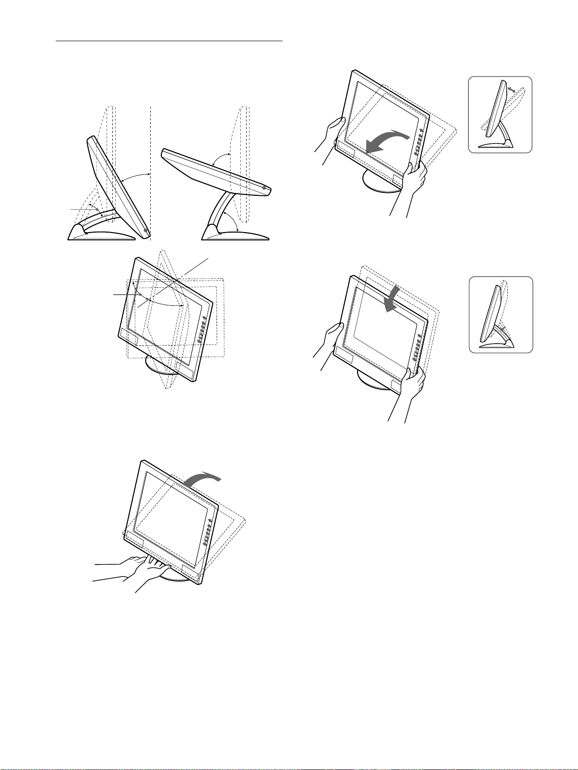
Réglage de l’inclinaison et de la
hauteur
Cet écran peut être réglé selon les angles illustrés ci-dessous.
70°
30°
40°
60°
45°
45°
2
Saisissez les côtésinférieurs de l’écran à cristaux
liquides, puis ajustez l’inclinaison de l’écran.
3
Saisissez les côtésinférieurs de l’écran à cristaux
liquides, puis ajustez la hauteur de l’écran.
Pour régler les angles, suivez la procédure suivante.
1
Saisissezlapartie médiane inférieure del’écran tout
en maintenant le support d’écran, puis inclinez
l’écran à cristaux liquides vers l’arrière.
Remarque
Lors du réglage de l’inclinaison et de la hauteur de l’écran, procédez
lentement et délicatement en veillant à ne pas cogner le panneau LCD
contre le bureau ou la base du supportd’écran.
Pour utiliser l’écran confortablement
Cet écran est conçudemanière à ce que vous puissiez le régler
suivant un angle de visualisation confortable. Ajustez l’angle de
visualisationde votre écran en fonction de la hauteur du bureau et
de votre chaise, de manière à ce que l’écran ne réfléchisse pas la
lumière dans les yeux.
10
 Loading...