

Sony SCDCE-775-ES Service manual

SCD-CE775
SERVICE MANUAL
Ver 1.0 2001.05
SPECIFICATIONS
When a super audio CD is played
Playing frequency range 2 Hz to 100 kHz
Frequency response 2 Hz to 50 kHz (–3 dB)
Dynamic range 103 dB or more
Total harmonic distortion rate
0.0020 % or less
Wow and flutter Value of measurable limit (±0.001 %
W. PEAK) or less
When a CD is played
Frequency response 2 Hz to 20 kHz
Dynamic range 98 dB or more
Total harmonic distortion rate
0.0025 % or less
Wow and flutter Value of measurable limit (±0.001 %
W. PEAK) or less
Output connector
Jack type
ANALOG OUT
DIGITAL (CD)
OUT OPTICAL*
PHONES
*Output only the audio signals of the CD
Phono
jacks
Square
optical
output
connector
Stereo
phone jack
Output level
2 Vrms
(at 50 kilohms)
–18 dBm
10 mW
Load impedance
Over 10 kilohms
Light emitting
wave length:
( )
660 nm
32 ohms
US Model
Canadian Model
Model Name Using Similar Mechanism NEW
CD Mechanism Type CDM59A-DVBU5A
Base Unit Name DVBU5A
Optical Pick-up Name KHM-230AAA
General
Laser Semiconductor laser
(SACD: λ = 650 nm)
(CD: λ = 780 nm)
Emission duration: continuous
Laser radiant power: 5.47 uW at 650 nm
*These output is the value measured at a distance of about
200mm from the objective lens surface on the optical pick-up.
Power requirements 120 V AC, 60 Hz
Power consumption 25 W
Dimensions (w/h/d) 430 × 108 × 400 mm
(17 × 4 1/4 × 15 3/4 in.)
incl. projecting parts
Mass (approx.) 5.9 kg (13 lbs 1 oz.)
Supplied accessories
• Audio connecting cord
phono jack × 2 (Red and White) y phono jack× 2 (Red
and White) (2)
phono jack × 1 (Black) y phono jack × 1 (Black) (2)
• Monaural (2P) mini-plug cord (1) (Connecting cord for
CONTROL A1
• Remote commander (remote) RM-SC500 (1)
• R06 (size-AA) batteries (2)
Design and specifications are subject to change without notice.
) (supplied for Canadian models only)
SUPER AUDIO CD PLAYER
9-873-915-11 Sony Corporation
2001E0500-1 Home Audio Company
C 2001.5 Shinagawa Tec Service Manual Production Group

SCD-CE775
TABLE OF CONTENTS
1. SERVICING NOTES ............................................... 4
2. GENERAL ................................................................... 6
3. DISASSEMBLY
3-1. Disassembly Flow ........................................................... 9
3-2. Case (409538) ................................................................. 10
3-3. Front Panel Section ......................................................... 10
3-4. CD Mechanism Deck (CDM59A-DVBU5A) ................ 11
3-5. AUDIO Board ................................................................. 11
3-6. POWER Board ................................................................ 12
3-7. MAIN Board ................................................................... 12
3-8. Base Unit (DVBU5A) ..................................................... 13
3-9. Table Assy ....................................................................... 13
3-10. SENSOR Board............................................................... 14
3-11. LOADING MOTOR Board ............................................ 14
4. ASSEMBLY................................................................. 15
5. TEST MODE.............................................................. 16
6. DIAGRAMS
6-1. Block Diagram – RF/SERVO Section – ........................ 30
6-2. Block Diagram – SERVO Section – .............................. 31
6-3. Block Diagram – MAIN Section – ................................ 32
6-4. Block Diagram – AUDIO Section – .............................. 33
6-5. Block Diagram – DISPLAY/KEY CONTROL/
POWER SUPPLY Section – ........................................... 34
6-6. Notes for Printed Wiring Boards and
Schematic Diagrams ....................................................... 35
6-7. Printed Wiring Board – RF Board – .............................. 36
6-8. Schematic Diagram – RF Board – ................................. 37
6-9. Printed Wiring Boards
– MOTOR/SENSOR Section –....................................... 38
6-10. Schematic Diagram – MOTOR/SENSOR Section – .... 39
6-11. Printed Wiring Board
– MAIN Board (Component Side) – .............................. 40
6-12. Printed Wiring Board
– MAIN Board (Conductor Side) – ................................ 41
6-13. Schematic Diagram – MAIN Board (1/5) – ................. 42
6-14. Schematic Diagram – MAIN Board (2/5) – .................. 43
6-15. Schematic Diagram – MAIN Board (3/5) – .................. 44
6-16. Schematic Diagram – MAIN Board (4/5) – .................. 45
6-17. Schematic Diagram – MAIN Board (5/5) – .................. 46
6-18. Schematic Diagram
– AUDIO/HEADPHONE Boards – ................................ 47
6-19. Printed Wiring Board
– AUDIO Board (Component Side) – ............................ 48
6-20. Printed Wir ing Boards – AUDIO (Conductor Side)/
HEADPHONE Boards – ................................................. 49
6-21. Printed Wiring Boards
– DISPLAY/KEY/LED Boards – ................................... 50
6-22. Schematic Diagram
– DISPLAY/KEY/LED Boards – ................................... 51
6-23. Printed Wiring Boards – POWER/REG Boards –......... 52
6-24. Printed Wir ing Boards – POWER SW/PT Boards – ..... 53
6-25. Schematic Diagram
– POWER/POWER SW/PT/REG Boards –................... 54
6-26. IC Pin Function Description ........................................... 63
7. EXPLODED VIEWS
7-1. Case Section .................................................................... 79
7-2. Front Panel Section ......................................................... 80
7-3. Chassis Section ............................................................... 81
7-4. CD Mechanism Deck Section-1
(CDM59A-DVBU5A)..................................................... 82
7-5. CD Mechanism Deck Section-2
(CDM59A-DVBU5A)..................................................... 83
7-6. Base Unit Section (DVBU5A)........................................ 84
8. ELECTRICAL PARTS LIST ............................... 85
2
SCD-CE775
r
Notes on chip component replacement
• Never reuse a disconnected chip component.
• Notice that the minus side of a tantalum capacitor may be damaged by heat.
Flexible Circuit Board Repairing
• Keep the temperature of the soldering iron around 270 ˚C during repairing.
• Do not touch the soldering iron on the same conductor of the
circuit board (within 3 times).
• Be careful not to apply force on the conductor when soldering
or unsoldering.
SAFETY CHECK-OUT
After correcting the original service problem, perform the following safety check before releasing the set to the customer:
Check the antenna terminals, metal trim, “metallized” knobs,
screws, and all other exposed metal parts for AC leakage.
Check leakage as described below.
LEAKAGE TEST
The AC leakage from any exposed metal part to earth ground and
from all exposed metal parts to any exposed metal part having a
return to chassis, must not exceed 0.5 mA (500 microamperes.).
Leakage current can be measured by any one of three methods.
1. A commercial leakage tester, such as the Simpson 229 or RCA
WT -540A. Follo w the manufacturers’ instructions to use these
instruments.
2. A battery-operated AC milliammeter. The Data Precision 245
digital multimeter is suitable for this job.
3. Measuring the voltage drop across a resistor by means of a
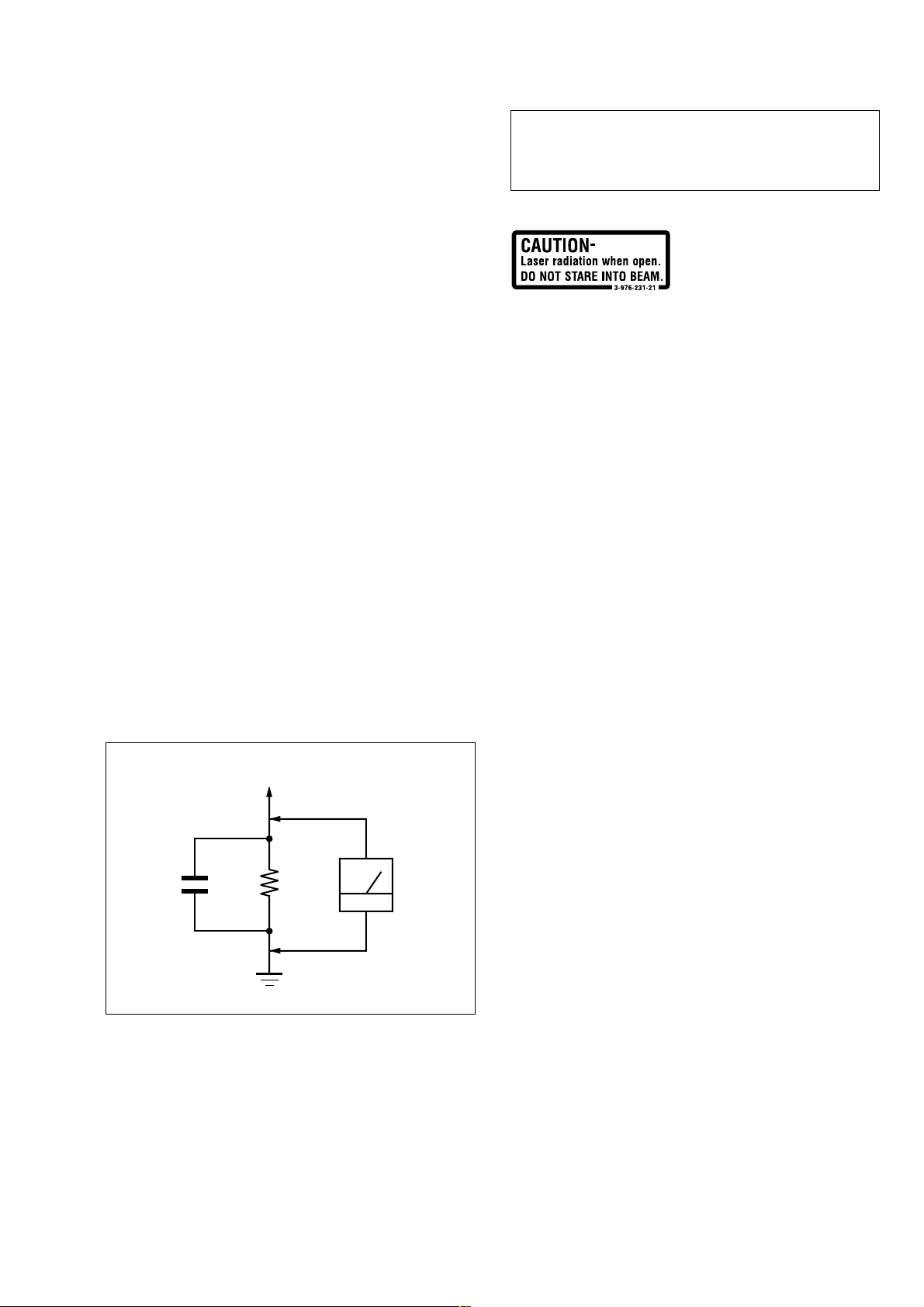
VOM or battery-operated AC voltmeter. The “limit” indication is 0.75 V, so analog meters must have an accurate lowvoltage scale. The Simpson 250 and Sanwa SH-63Trd are examples of a passive VOM that is suitable. Nearly all battery
operated digital multimeters that have a 2 V A C range are suitable. (See Fig. A)
CAUTION
Use of controls or adjustments or performance of procedures
other than those specified herein may result in hazardous radiation exposure.
This label is located on the LEFT exterior.
To Exposed Metal
Parts on Set
1.5 k
0.15 µF
Fig. A. Using an AC voltmeter to check AC leakage.
SAFETY-RELATED COMPONENT WARNING!!
COMPONENTS IDENTIFIED BY MARK 0 OR DOTTED
LINE WITH MARK 0 ON THE SCHEMATIC DIAGRAMS
AND IN THE PARTS LIST ARE CRITICAL TO SAFE
OPERATION. REPLACE THESE COMPONENTS WITH
SONY PARTS WHOSE PART NUMBERS APPEAR AS
SHOWN IN THIS MANUAL OR IN SUPPLEMENTS PUBLISHED BY SONY.
Ω
Earth Ground
AC
voltmete
(0.75 V)
ATTENTION AU COMPOSANT AYANT RAPPORT
À LA SÉCURITÉ!
LES COMPOSANTS IDENTIFIÉS P AR UNE MARQ UE 0
SUR LES DIAGRAMMES SCHÉMATIQUES ET LA LISTE
DES PIÈCES SONT CRITIQUES POUR LA SÉCURITÉ
DE FONCTIONNEMENT. NE REMPLACER CES COMPOSANTS QUE PAR DES PIÈCES SONY DONT LES
NUMÉROS SONT DONNÉS DANS CE MANUEL OU
DANS LES SUPPLÉMENTS PUBLIÉS PAR SONY.
3
SCD-CE775
SECTION 1
SERVICING NOTES
NOTES ON HANDLING THE OPTICAL PICK-UP
BLOCK OR BASE UNIT
The laser diode in the optical pick-up block may suffer electrostatic break-down because of the potential difference generated
by the charged electrostatic load, etc. on clothing and the human
body.
During repair, pay attention to electrostatic break-down and also
use the procedure in the printed matter which is included in the
repair parts.
The flexible board is easily damaged and should be handled with
care.
NOTES ON LASER DIODE EMISSION CHECK
The laser beam on this model is concentrated so as to be focused
on the disc reflective surface by the objective lens in the optical
pick-up block. Therefore, when checking the laser diode emission, observe from more than 30 cm away from the objectiv e lens.
LASER DIODE AND FOCUS SEARCH OPERATION
CHECK
Carry out the “S curve check” in “CD section adjustment” and
check that the S curve waveforms is output three times.
CLEANING OF OPTICAL PICK-UP LENS
In cleaning the lens of optical pick-up, use the air blower.
Never use a cotton swab for cleaning the lens of optical pick-up,
which otherwise causes a trouble.
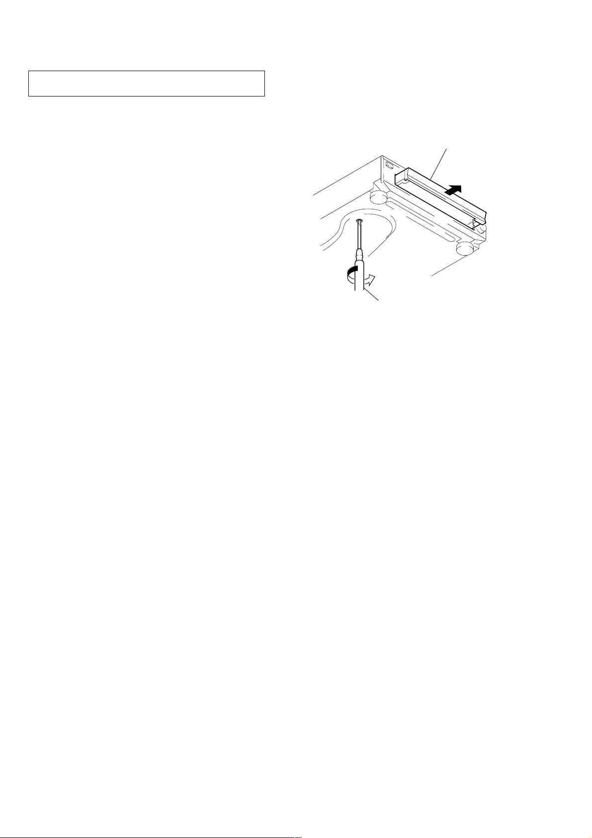
HOW TO OPEN THE DISC TABLE WHEN PO WER
SWITCH TURNS OFF
Insert a tapering driver into the aperture of the unit bottom, and
turn it in the direction of the arrow (to OUT direction).
table
tapering driver
*
To close the disc table, turn the tapering
driver in the reverse direction (to IN direction).
CHECKING SIGNALS OF CD SECTION
Efficiency to check each signal of CD section is increased when
the test points on the MAIN board are used.
Refer to 5-8. WAVEFORMS CHECK (28 page)
4

RESETTING OPERATION AT POWER ON
If the power is turned on with a disc loaded in the set, a sequence of operation as shown below will be performed.
(The operation varies depending on the type of disc) Condition: continue mode
SCD-CE775
(1) CD
1. Sled reverse move (sled in)
2. Disc detect
3. IC setting for CD
4. Servo error signal offset auto adjustment
5. Spindle kick for LD on
6. LD on
7. Focus search
8. Focus servo on
9. Spindle kick
10. Spindle servo on
11. E-F balance auto adjustment
12. Tracking & sled servo on
13. Focus bias auto adjustment
14. Focus servo gain auto adjustment
15. Tracking servo gain auto adjustment
16. Jump to lead-in area
17. Read TOC
18. Stop
(2) SACD (single layer)
1. Sled reverse move (sled in)
2. Disc detect
3. IC setting for SACD
4. Servo error signal offset auto adjustment
5. Spindle kick for LD on
6. LD on
7. Focus search
8. Focus servo on
9. Spindle kick
10. Spindle servo on
11. E-F balance auto adjustment
12. Tracking & sled servo on
13. Focus bias auto adjustment
14. Focus servo gain auto adjustment
15. Tracking servo gain auto adjustment
16. Jump to lead-in area
17. Read TOC
18. Stop
(3) SACD (dual layer)
1. Sled reverse move (sled in)
2. Disc detect
3. IC setting for SACD
4. Servo error signal offset auto adjustment
5. Spindle kick for LD on
6. LD on
7. Focus search
8. Focus servo on (layer 0)
9. Spindle kick
10. Spindle servo on
11. E-F balance auto adjustment (layer 0)
12. Tracking & sled servo on (layer 0)
13. Focus bias auto adjustment (layer 0)
14. Focus servo gain auto adjustment (layer 0)
15. Tracking servo gain auto adjustment (layer 0)
16. Jump to lead-in area
17. Read TOC
18. Focus jump (layer 0tlayer 1)
19. E-F balance auto adjustment (layer 1)
20. Tracking & sled servo on (layer 1)
21. Focus bias auto adjustment (layer 1)
22. Focus servo gain auto adjustment (layer 1)
23. Tracking servo gain auto adjustment (layer 1)
24. Focus Jump (layer 1tlayer 0)
25. Stop
5
SCD-CE775
SECTION 2
GENERAL
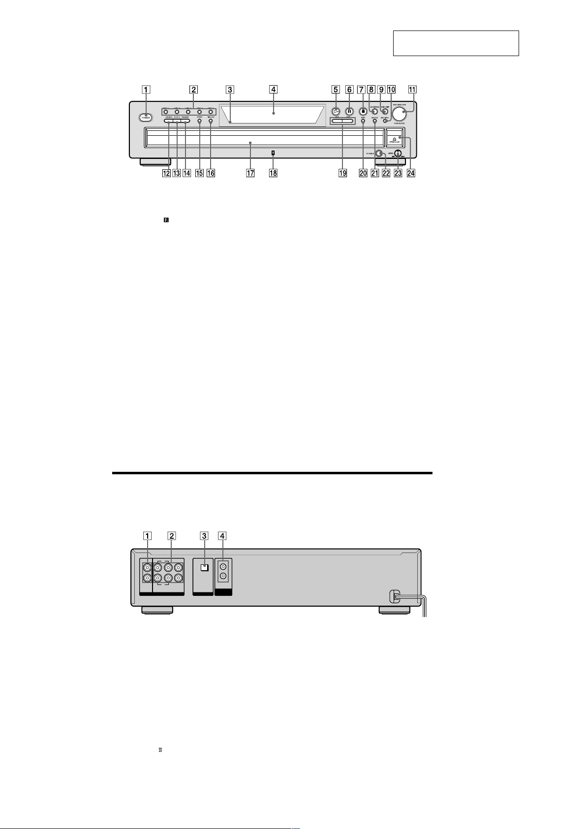
Front Panel Parts Descriptions
This section is extracted from
instruction manual.
1 POWER switch (11)
Press to turn on/off the player.
2 DISC 1–5 button (12)
Press to select the disc.
3 Remote sensor
4 Display window (12)
Shows various information.
5 N button (12)
Press to start play.
6 X button (12)
Press to pause play.
7 x button (12)
Press to stop play.
8 EX-CHANGE button (15)
Press to replace discs while playing a disc.
9 DISC SKIP button (11)
Press to select the disc.
0 MULTI/2CH button (with an LED) (12)
Press to select the playback area when the 2 channel +
Multi-channel Super Audio CD is loaded. When you
select the Multi-channel playback area (page 11), the
LED turns on.
qa lAMSL dial (AMS: Automatic Music Sensor)
(6, 12)
When you turn the lAMSL dial
counterclockwise by one click, you go back to the
preceding track; when you turn the lAMSL dial
clockwise by one click, you go to the succeeding track.
qs CONTINUE button (11)
Press to resume normal play from Shuffle Play or
Program Play.
qd SHUFFLE button (19)
Press to select Shuffle Play.
qf PROGRAM button (20)
Press to select Program Play.
(4)
qg REPEAT button (18)
Press repeatedly to play all tracks or only one track on
the disc.
qh TIME/TEXT button (13)
Each time you press the button, the playing time of the
track, the total remaining time on the disc, or TEXT
information appears in the display.
qj Disc tray (11)
Press A OPEN/CLOSE to open/close the disc tray.
qk MULTI CHANNEL DECODING indicator
Turns on when you turn on the player, or when the
Multi-channel Super Audio CD is loaded and select
the Multi-channel playback area by pressing MULTI/
2CH.
ql m/M buttons (17)
Press to locate a portion you want to play within a
track.
w; MENU button (6)
Press to enter the menu.
wa SACD/CD button (with an LED) (12)
Each time you press the button while the Hybrid disc
(page 10) is loaded, the layer changes between an HD
(SACD) layer (the LED turns on) and CD layer (the
LED turns off).
ws PHONES jack
Connect the headphones.
During playback of a Multi-channel Super Audio CD,
the same signal that is output from the ANALOG
5.1CH FRONT L/R jacks is output from the PHONES
jack.
wd PHONES LEVEL control
Adjust the headphones volume.
wf A OPEN/CLOSE button (11)
Press to open/close the disc tray.
Rear Panel Parts Descriptions
L
R
SURRFRONT
5.1CH OUT
ANALOG
jacks (6, 26)
CENTER
SUB
WOOFER
OPTICAL
OUT
DIGITAL (CD)
CONTROL
A1
ΙΙ
L
R
2CH OUT
1 ANALOG 2CH OUT L/R jacks (5)
Connect to an audio component (stereo/2 channel)
using the audio connecting cord.
2 ANALOG 5.1CH OUT jacks (4)
Connect to an amplifier equipped with the 5.1CH
input jacks (Multi-channel amplifier, AV amplifier,
etc.) using the audio connecting cords.
3 DIGITAL (CD) OUT OPTICAL connector (6)
Connect to an audio component using an optical
digital cable.
4 CONTROL A1
Connect to a Sony audio component using the
monaural (2P) mini-plug cord.
Note
Only the audio signals of the CD can be output from the
DIGITAL (CD) OUT connectors shown in 3. Those of the Super
Audio CD cannot be output through DIGITAL (CD) OUT.
6
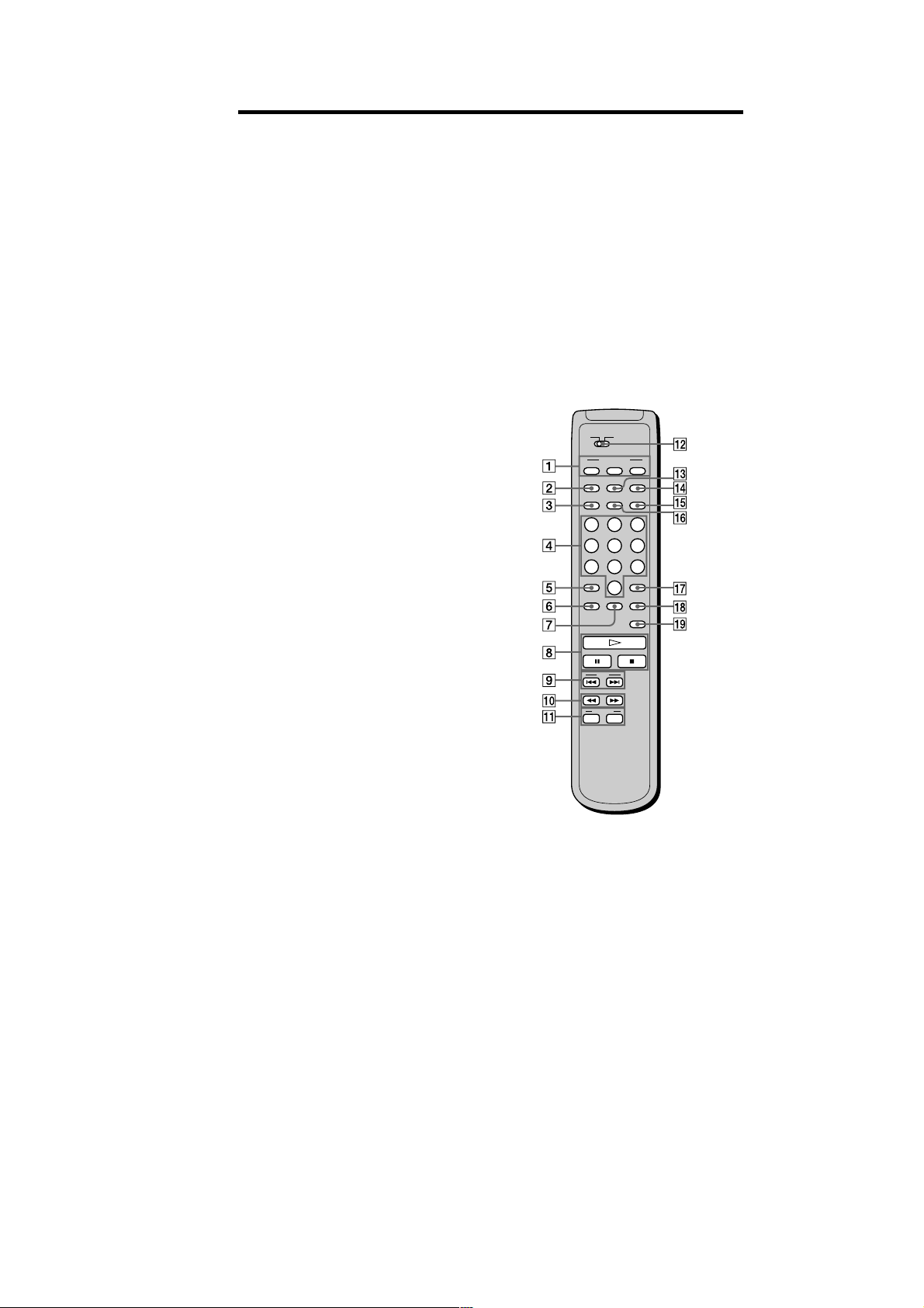
Remote Parts Descriptions
SCD-CE775
1 CONTINUE button (11)
Press to resume normal play from Shuffle Play or
Program Play.
SHUFFLE button (19)
Press to select Shuffle Play.
PROGRAM button (20)
Press to select Program Play.
2 NAME INPUT button (25)
Press to enter the name input mode.
3 DISC/CAPS button (16, 25)
Press to select the disc.
Press to select the capital letter in name input mode.
4 Number buttons (16)
Press to enter the track numbers.
5
i
10 button (16)
Press to locate a track numbered over 10.
6 REPEAT button (18)
Press repeatedly to play all tracks or only one track on
the disc.
7 CHECK button (20)
Press to check the programmed order.
8 H button (12)
Press to start play.
X button (12)
Press to pause play.
x button (12)
Press to stop play.
9 AMS ./> (AMS: Automatic Music Sensor)
buttons (16)
Press to locate a specific track.
0 m/M buttons (17)
Press to locate a portion you want to play within a
track.
qa DISC SKIP +/– buttons (16)
Press to select the disc.
qs CD1/2 (COMMAND MODE) switch (6)
Select the command mode.
qd DISPLAY MODE button (13)
Press to turn off the information.
qf SACD/CD button (12)
Each time you press the button while the Hybrid disc
(page 10) is loaded, the layer changes between an HD
layer (the SACD/CD LED turns on) and CD layer (the
SACD/CD LED turns off).
qg MULTI/2CH button (12)
Press to select the playback area when the 2 channel +
Multi-channel Super Audio CD is loaded. When you
select the Multi-channel playback area (page 11), the
MULTI/2CH LED turns on.
qh TIME/TEXT/SPACE button (13, 25)
Each time you press the button, the playing time of
the track, the total remaining time on the disc, or
TEXT information appears in the display.
Press to insert a space in name input mode.
qj ENTER button (25)
Press to decide the selection.
qk CLEAR button (20)
Press to delete a programmed track number.
ql LEVEL ADJ button (23)
Press to adjust the output level balance for the Multichannel management function (page 24).
CD1
CD2
PLAY MODE
CONTINUE SHUFFLE
PROGRAM
DISPLAY
NAME
SACD/CD
MODE
INPUT
TIME/TEXT
DISC
MULTI/2CH
SPACE
CAPS
ABC DEF&!?
123
JKL MNOGHI
456
TUV WXYZPQRS
78
9
>10 ENTER
10/0
REPEAT CHECK
AMS
DISC SKIP
—+
CLEAR
LEVEL
ADJ
7
SCD-CE775
Compatible Disc Types
You can play the following discs with this player.
Depending on the type of disc to be played, select the
appropriate indicator by pressing SACD/CD or MULTI/
2CH (pages 12).
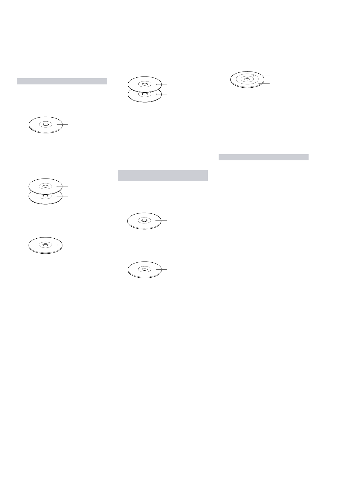
Classification by the layer configuration
Super Audio CD (single layer disc)
This disc consists of a single HD (high density) layer.
When you play this disc, the player is set to the Super
Audio CD playback mode automatically.
HD (Super Audio CD)
layer
Super Audio CD (dual layer disc)
This disc consists of dual HD layers and is capable of
extended play over long periods.
When you play this disc, the player is set to the Super
Audio CD playback mode automatically.
Also, as the dual layer disc consists of dual HD layers on
one side only, it is not necessary to turn the disc over.
HD (Super Audio CD)
layer
HD (Super Audio CD)
layer
Conventional CD
This disc is the standard format.
When you play this disc, the player is set to the
Conventional CD playback mode automatically.
Super Audio CD + CD (Hybrid disc)
This disc consists of an HD layer and a CD layer. Press
SACD/CD to select the layer you want to listen to. Also,
as the dual layers are on one side, it is not necessary to
turn the disc over. You can play the CD layer using a
conventional CD player.
CD layer
HD (Super Audio CD)
layer
You can select the default playback layer (HD or CD).
1
During stop mode, press MENU.
2
Turn l AMS L to until “LAYER SELECT”
appears in the display.
3
Press l AMS L.
The current default layer appears.
4
Turn lAMSL to select CD or SACD, then push
lAMSL again.
The default layer setting is SACD.
Classification by the channel
configuration of the Super Audio CD
2 channel Super Audio CD
This disc consists of the 2 channel playback area.
When you play this disc, the player is set to the 2 channel
playback mode automatically.
2 channel playback area
2 channel + Multi-channel Super Audio CD
This disc consists of the 2 channel playback area and the
multi-channel playback area.
Press MULTI/2CH to select the playback area you want to
listen to.
2 channel playback area
Multi-channel playback
area
You can select the default playback area (2 channel
playback or multi-channel playback area).
1
During stop mode, press MENU.
2
Tur n l AMS L to until “M/2CH SELECT”
appears in the display.
3
Press l AMS L.
The current playback area appears.
4
Tur n l AMS L to select desired playback area,
then press l AMS L.
Incompatible Discs
This player cannot play the following discs. If you try to
play them, the error message “TOC Error” or “No Disc”
will appear or there will be no sound.
• CD-ROM
• DVD, etc.
CD layer
Multi-channel Super Audio CD
This disc consists of the multi-channel playback area.
When you play this disc, the player is set to the multichannel playback mode automatically.
Multi-channel playback
area
8
SECTION 3
DISASSEMBLY
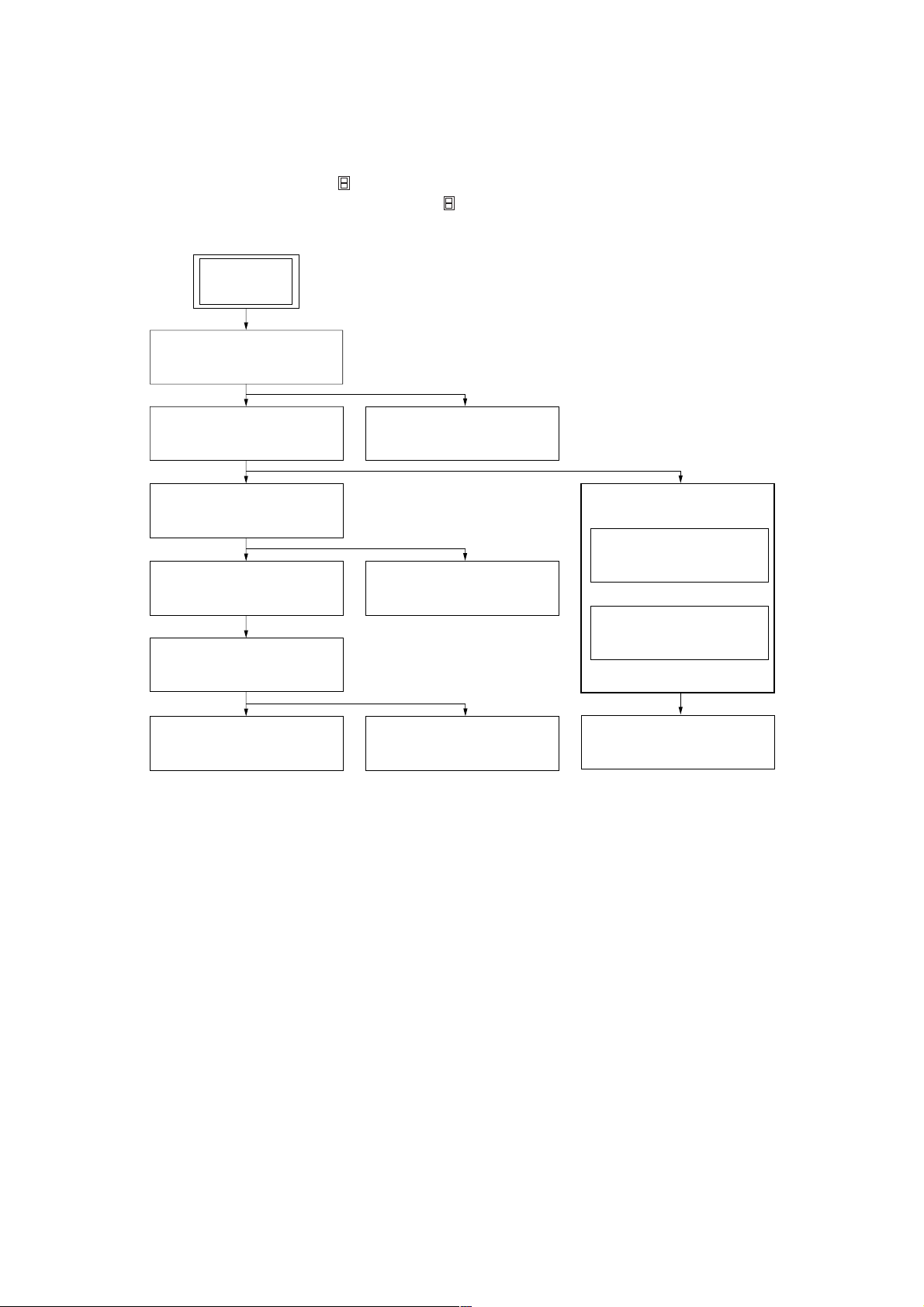
• This set can be disassembled in the order shown below.
3-1. DISASSEMBLY FLOW
Note 1: The process described in can be performed in any order.
Note 2: Without completing the process described in , the next process can not be performed.
Note 3: Illustration of disassembly is omitted.
SET
3-2. CASE (409538)
(Page 10)
SCD-CE775
3-3. FRONT PANEL SECTION
(Page 10)
3-4. CD MECHANISM DECK
(CDM59A-DVBU5A)
(Page 11)
3-8. BASE UNIT (DVBU5A)
(Page 13)
3-9. TABLE ASSY
(Page 13)
3-10.SENSOR BOARD
(Page 14)
3-5. AUDIO BOARD
(Page 11)
3-6. POWER BOARD
(Page 12)
3-11.LOADING MOTOR BOARD
(Page 14)
3-4. CD MECHANISM DECK
(CDM59A-DVBU5A)
(Page 11)
3-5. AUDIO BOARD
(Page 11)
3-7. MAIN BOARD
(Page 12)
9
SCD-CE775
)
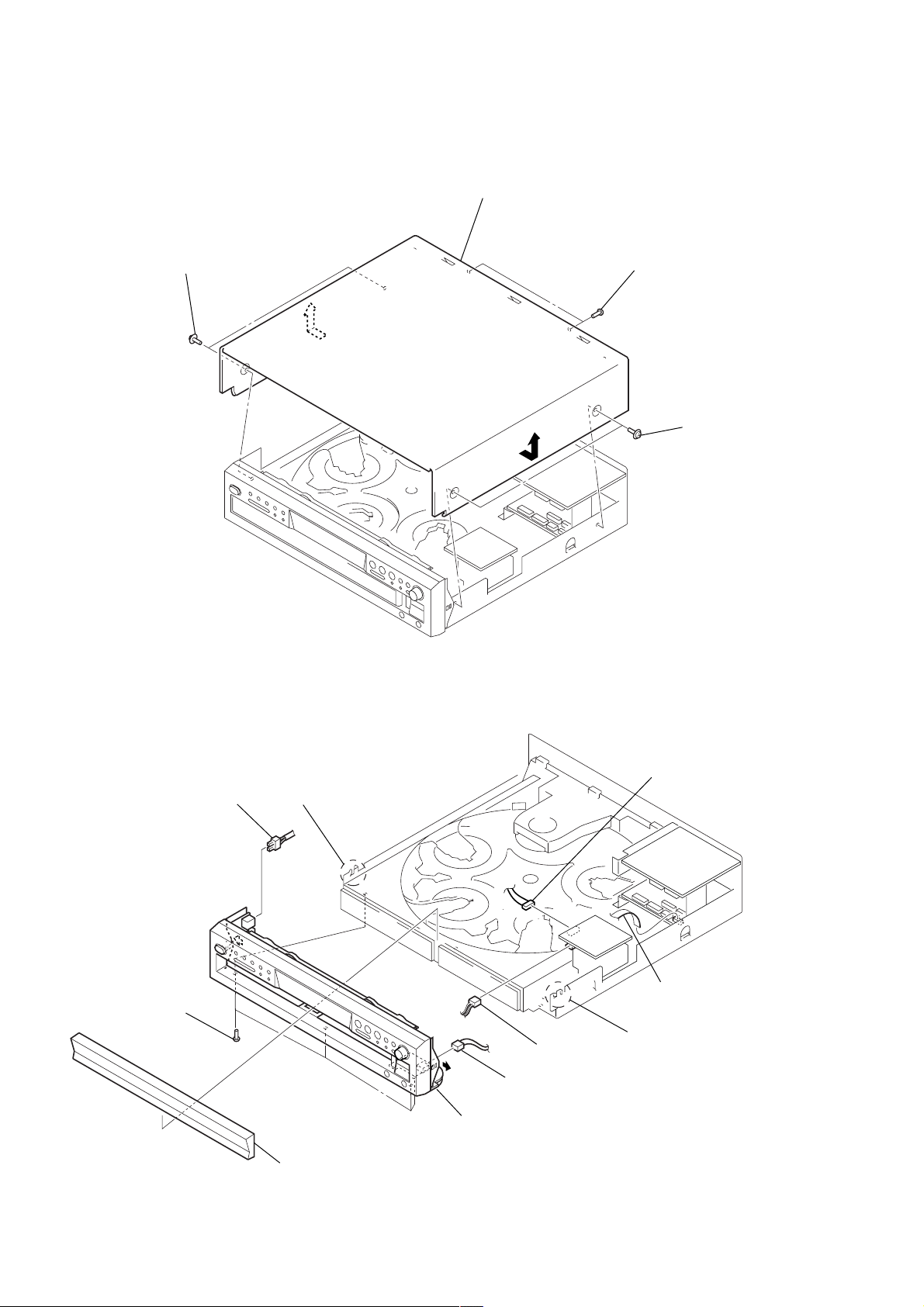
Note: Follow the disassembly procedure in the numerical order given.
3-2. CASE (409538)
1
two screws
(case3 TP2)
3
case (409538)
2
two screws
(BVTP3 × 8)
1
two screws
(case3 TP2
3-3. FRONT PANEL SECTION
6
7
four screws
(BVTP3
×
8)
connector
(CN601)
8
claw
5
connector
(CN881)
9
front panel section
4
connector
(CN153)
3
connector
(CN104)
2
wire (flat type) (12 core)
(CN706)
8
claw
10
1
loadind panel
Note: When removing the loading panel,
refer to "Section 1. Servicing Notes" on page 4.

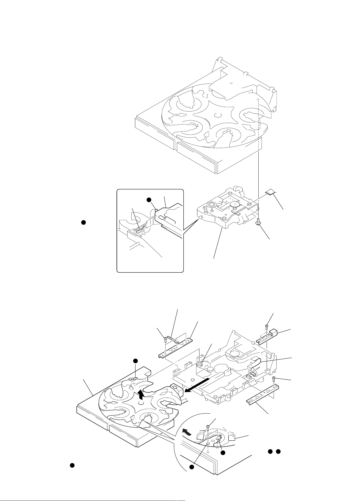
3-4. CD MECHANISM DECK
(CDM59A-DVBU5A)
4
screw
(BVTP3
3
Slide the tray until the screw
that fixes the table assy can be
seen through around hole
in the table assy.
×
8)
a
a
6
three screws
(BVTP3
SCD-CE775
9
CD mechanism deck
×
8)
7
(CDM59A-DVBU5A)
5
two screws
(BVTP3
8
wire (flat type) (30 core)
(CN708)
5
×
8)
screw
(BVTP3
×
8)
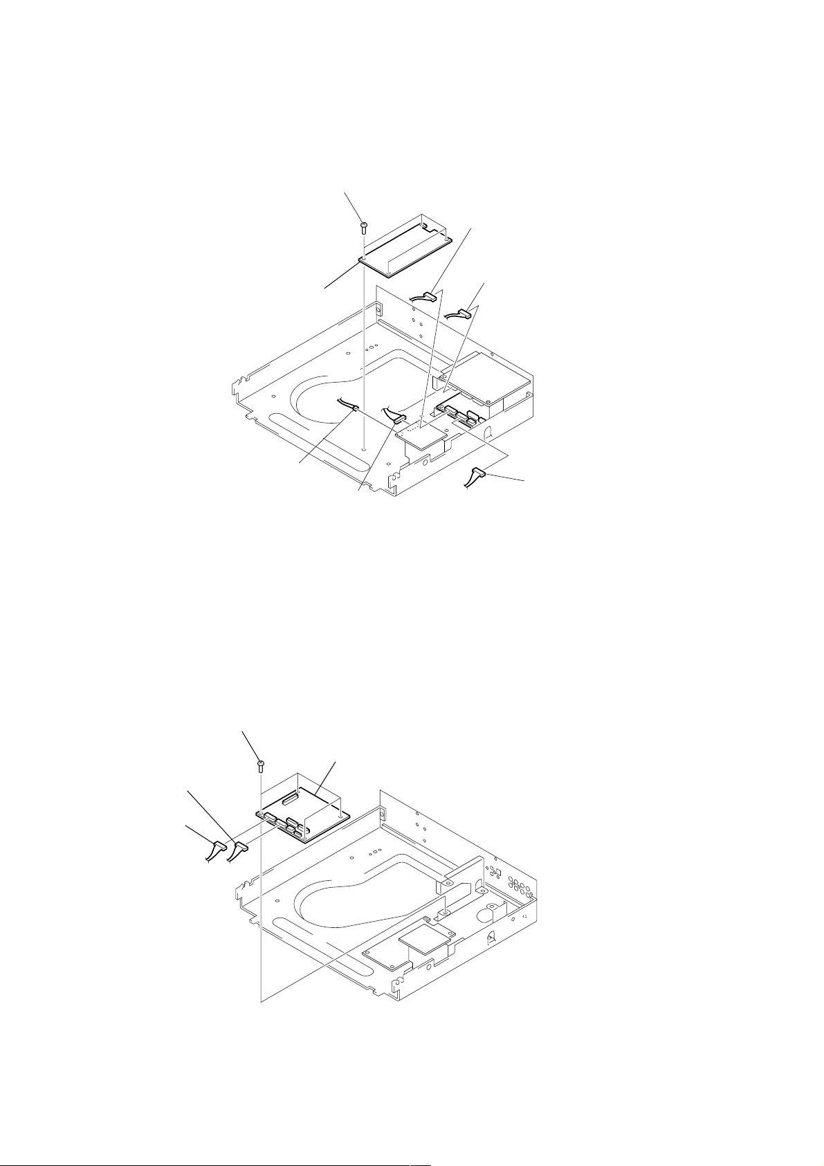
3-5. AUDIO BOARD
2
connector
(CN301)
5
four screws
(BVTP3 × 8)
1
connector
(CN705)
2
Insert a tapering driver from the bottom of the chassis,
and turn it in the direction of the arrow until the base unit
goes down to the lowest position.
6
AUDIO board
1
wire (flat type) (19 core)
(CN702)
4
five screws
(BVTP3 × 8)
1
wire (flat type) (19 core)
(CN701)
3
connector (CN704)
11
SCD-CE775
r
3-6. POWER BOARD
4
5
POWER board
four screws
(BVTP3
×
8)
3
connector
(CN707)
2
connector
(CN301)
3-7. MAIN BOARD
1
connector
(CN705)
1
connector
(CN707)
2
four screws
(BVTP3
1
×
8)
connector
(CN105)
1
connector
(CN151)
3
MAIN board
3
connecto
(CN705)
12
)
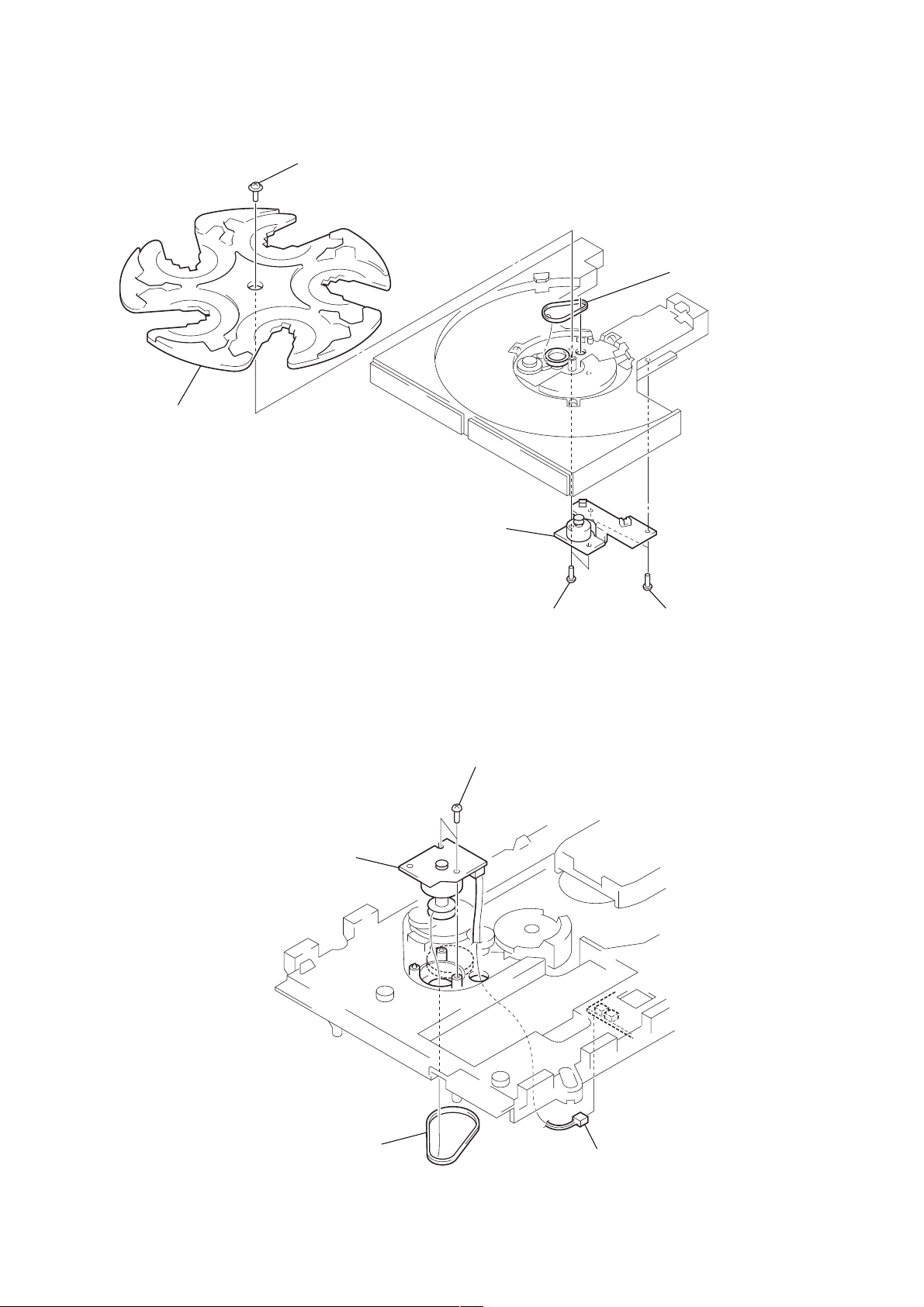
3-8. BASE UNIT (DVBU5A)
SCD-CE775
Note: When installing the BU
on the chassis, set the
lever (lifter) in free
position, the gear (U/D)
in UP position, and insert
the shaft into the
groove of gear (U/D).
b
3-9. TABLE ASSY
gear (U/D)
9
e
BU section
b
three screws
(BTTP M2.6)
q;
3
base unit (DVBU5A)
clamp
qa
bracket (guide)
gear
(loading C)
1
wire (flat type) (25 core
(CN003)
2
two screws
(PTPWH M2.6), floating
7
two screws
(BTTP M2.6)
8
bracket (guide 2)
4
wire (flat type)
(6 core) (CN15)
qs
table assy
Note: When installing the table assy
on the chassis assy, engage
the gear (loading C) with the groove
by looking into the gear through
a hole in the table assy.
e
3
5
screw
(BTTP M2.6)
2
two screws
(BTTP M2.6)
1
d
c
6
bracket (guide)
Slide the tray until the screw
that fixes the bracket (guide)
can be seen through a round
hole , in the table assy.
c
d
13
SCD-CE775
3-10. SENSOR BOARD
2
tray
1
screw
(PTPWH M2.6)
3
belt (rotary)
3-11. LOADING MOTOR BOARD
4
LOADING MOTOR board
5
SENSOR board
4
3
two screws
(BTTP M2.6)
two screws
(BTTP M2.6)
4
two screws
(BTTP M2.6)
14
1
belt (loading)
2
connector
(CN13)
SECTION 4
ASSEMBLY
Note: Follow the assembly procedure in the numerical order given.
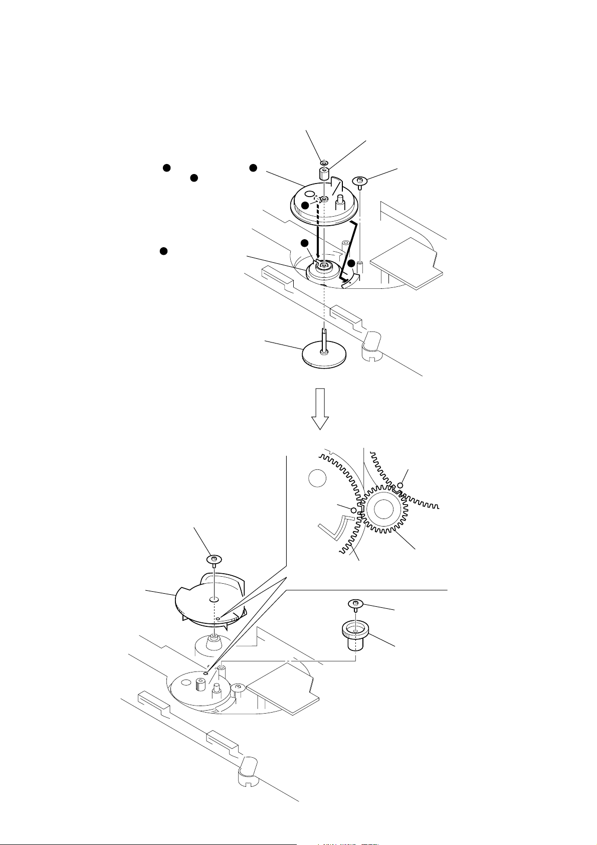
ADJUSTING PHASE OF SWING GEAR AND GEAR (U/D)
5 stopper washer (FR)
3 Let the swing gear through under the
chassis and engage its dowel
with the groove of rotary encoder.
h
f
g
g
SCD-CE775
4 Push fully the shaft of shaft gear and
align the hole shape of gear (loading B).
6 screw
(PTPWH M2.6)
2 Install the rotary encoder so that
its groove comes to the position
shown in the figure.
f
1 Insert the shaft gear up to the
position where its shaft comes
out by 5 mm.
8 screw
(PTPWH M2.6)
f
h
circle mark
circle mark
7 gear (U/D)
gear (RV)
swing gear
Fig. A
q; screw
(PTPWH M2.6)
9 gear (RV)
Note: Align swing gear, a circle mark
on the gear (U/D), and the teeth
of gear (RV) to the position
showing in the Fig. A.
15
SCD-CE775
SECTION 5
TEST MODE
This set automatically executes self-diagnosis and various checks
by entering the test mode.
Note: This set automatically makes various adjustments according to the
type of disc, thereby not requiring adjustment of the set when parts
were replaced. However, be sure to execute 5-1. IC AND FLUORESCENT DISPLAY TUBE CHECK, 5-2. AUTO CHECK and 5-
8. WAVEFORMS CHECK.
Disc for Test Mode
Various checks of this set require the following discs.
Model Type *1 Category Application
MODEL
SATD-S5
(J-2501-215-A) SL
SATD-S4 Optical waveform check
(J-2501-184-A)
Not specified DL 12 cm disc Operation check
PATD-012
(4-225-203-01)
YEDS-18 Reference disc
(3-702-101-01)
Not specified HYBRID 12 cm disc Operation check
CD
12 cm disc
Reference disc
12 cm disc
Adjusted value check,
Operation check,
Adjusted value check,
Operation check,
Optical waveform check
*1 SL: Single Layer
DL: Dual Layer
Setting Method of Test Mode
Turn the [POWER] switch on while pressing the [ AMS ]
lL
dial and the [MENU] button. Release the [MENU] button and the
lL
[ AMS ] dial in this order when “Test Mode Menu” is
displayed on the fluorescent display tube. (If the [ AMS ]
lL
dial is released first, the test mode becomes active b ut “T est Mode
Menu” is not displayed)
[ OPEN/CLOSE] key in the TEST mode.
A
A
The [ OPEN/CLOSE] key is disabled immediately after the machine enters the TEST mode. Be sure to turn the [ AMS ] dial
to select 59 T a ble Init and push [ AMS ] once. When initial-
lL
lL
ization of the table is completed, the message INITAIL OK appears
several seconds on the FL display. After this, the [ OPEN/CLOSE]
A
key is enabled and disc can be inserted and ejected.
When the command 59 T able Init is ex ecuted, the same operations
of the POWER ON to the disc chucking in the normal operations
as described below are performed. However, it presumes that the
door and the tray are closed depending on the stop status.
59 Table Init t BU DOWN (disc unchucking) t Table rotates
(disc search) t BU UP (disc chucking) at the disc that is found
first of all.
When there are no discs, BU UP is executed at the DISC1 position.
Releasing Method of Test Mode
To release the test mode, turn the [POWER] switch off.
Selection/Entry of Test Mode
To select and enter the “Test Mode Menu”, operate as follows.
1. Rotate the [ AMS ] dial to select the menu, and press
the [ AMS ] dial to enter.
lL
lL
2. The test is switched on or off alternately each time the
lL
[ AMS ] dial is pressed.
3. To return to the pre vious ste p, rotate the [ AMS ] dial
to select the desired item, and press the [ AMS ] dial
lL
lL
to enter.
Test Mode Command List
The contents of test mode are as follows.
Note: Wrong operation in the test mode causes a trouble, thus requiring extreme care.
LINE command (1X): Use mainly for a manufacturing line.
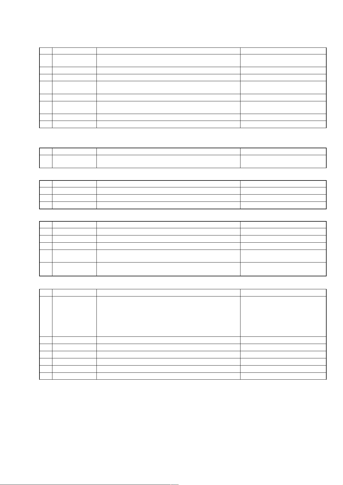
No. Name Description Remarks
05 DSP MON1 XUGF, XPCK, C2PO outputted from IC509 (CD DSP) Not used for the servicing
06 DSP MON2 MNT0, MNT1, MNT2, MNT3 outputted from IC509 (CD DSP) Not used for the servicing
07 DSP MON3 RFCK, XPCK, XROF, GTOP outputted from IC509 (CD DSP) Electrical measurement,
CD CLV jitter measurement
STANDARD command (1X): Use when the servo is applied by manual operation.
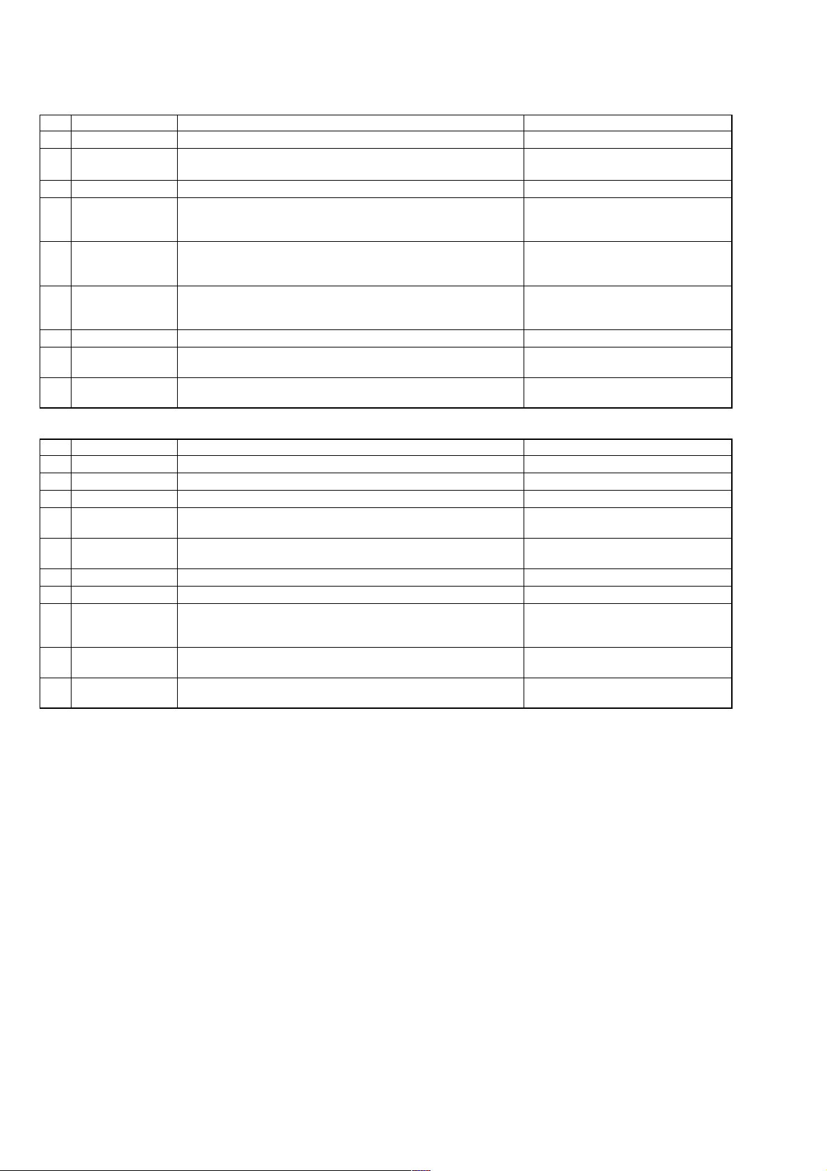
No. Name Description Remarks
12 LD ON/OFF The laser diode is turned on or off On or off are switched alternately
13 SPIN ON/OFF The spindle motor is rotated with the regulated voltage On or off are switched alternately
14 FSRV ON/OFF The focus servo is turned on or off On or off are switched alternately
15 TSRV ON/OFF The tracking servo is turned on or off On or off are switched alternately
16 CLV ON/OFF The spindle SLV servo is turned on or off On or off are switched alternately
17 SSRV ON/OFF The sled servo is turned on or off On or off are switched alternately
18 ALL SRV ON All servos are turned on
19 ALL SRV OFF All servos are turned off Stop command in the test mode
Focus and tracking servos must be already turned on
Focus, tracking and spindle servos must be already turned on
16
SCD-CE775
FOCUS command (2X): Focus related. (All servos must be already turned on (except command 21))
No. Name Description Remarks
21 FSRCH ON/OFF The continuous vertical motion of the optical pick-up lens is turned on or Avoid a long-time use
22 F-BIAS UP Increase focus bias Focus bias value
23 F-BIAS DOWN Decrease focus bias Focus bias value
24 ADJ FCSBIAS The focus bias is adjusted automatically
25 FGAIN UP/DW The focus servo gain is switched between normal and down Normal or down are switched alternately
26 FJMP UP/DWN Focus jump is executed Valid only for DL
27 FOCUS AGC The focus servo gain is adjusted automatically
28 DISP FBdata The focus bias adjusted value is displayed Hexadecimal display 9 bit data
Note: On or off and up or down are switched alternately
OFFSET (PI, FE, TE) command (3X): Adjusts the offset of PI, FE and TE signals.
No. Name Description Remarks
31 PI/FE OFSET Adjusts the offset of PI, FE and TE signals TE offset adjustment is executed for the CD
TRACKING command (4X): Tracking servo related.
No. Name Description Remarks
41 TGAIN NM/UP The tracking servo gain is switched between normal and up Normal or up are switched alternately
44 ADJ TRK DSP The traverse AGC and E-F balance adjustment is performed
45 TRACKING AGC The tracking servo gain is adjusted automatically
off
Both + and - directions are searched to search for best jitter point
UP: layer 0t1, DOWN: layer 1t0
This adjustment must be executed after 61 DISC DETECT only
SEARCH command (5X): Track search related. (Nos. 51 through 53 are not used for the servicing.)
No. Name Description Remarks
51 1-TRCK JUMP One-track jump is performed
52 M-TRCK MOVE M-track movement is performed
53 FINE SEARCH Fine search is performed
58 CDM Check Measurement of table rotation hours, tray open/close hours and panel door
59 Table Init Initializes the table. After this command, the [ OPEN/CLOSE]
open close hours
A
key is enabled.
DISC DETECT command (6X): Disc type check related.
No. Name Description Remarks
61 DISC DETECT Disc type check is executed Refer to how to apply servo by manual
62 SET DISC CD Enter disc type CD setting CD forced setting
63 SET DISC SL Enter disc type SL setting SL forced setting
64 SET DISC DD Enter disc type DD setting DD forced setting
65 SET DISC HH Enter disc type HYBRID HD setting HD forced setting
66 SET DISC HC Enter disc type HYBRID CD setting CD forced setting
6F Download Not used for the servicing
Display after judgment operation (18 page)
DSKMOD CD: Judged as CD
DSKMOD SL: Judged as SACD (SL)
DSKMOD DL: Judged as SACD (DL)
DSKMOD HLHD: Judged as HYBRID HD
DSKMOD CDRW: Judged as CD-RW
17
SCD-CE775
TOOLS command (8X): Performs aging, reads adjusting parameters, etc.
No. Name Description Remarks
81 VERSION Firmware version is displayed Example: Ver 1.00
83 TRAY AGING Tray open-close aging is performed Number of times and eccentricity
Not used for the servicing measurement Not used in this set.
84 JITTER Jitter measurement Not used for the servicing
85 ERROR RATE Error rate measurement Error rate
86 ALL SRV ON Apply all servos Use when applying the servo by
87 DISP ADJ DT Automatic adjusting parameters are displayed Refer to auto check items (21 page)
8A FL TEST Not used for the servicing
8d Set Up Init Set to factory shipping mode Set when repair completed
8F 49 TRCK JIT Used for jitter measurement of 49th music on SACD-S4 For manufacturing line
QA command (9X)
No. Name Description Remarks
91 F.JMP CHECK Not used for the servicing
92 SET CHECK The set is checked Refer to 5-2. AUTO CHECK (21 page)
93 WATER MARK Not used for the servicing
94 SET AGING The set aging is performed Refer to 5-6. AGING MODE (26 page)
95 DISPLAY ERROR The content of error recorded to the set is read and displayed Refer to Error Display list (27 page)
96 D-OUT OnOff Digital out of CD is turned on or off Not used in this set.
98 APDO JITTER Not used for the servicing
9C BU DENCHO The content of error recorded to the set is read, and then the S curve Refer to 5-8.WAVEFORMS CHECK
9D P-ON HOUR Approximate cumulative power supplying time is displayed In unit of 1 hour
9E RFD OUT RFD output is turned on or off Not used for the servicing
CD: C1, C2 Not used for the servicing
SACD: PO, PI1, PI2
Full automatic measurement including PI, FE and TE offset adjustment is manual operation
performed Refer to STANDARD command (16 page)
The offset adjusted values are scroll-displayed in order of RF, VC, FE and
TE Refer to auto check items (21 page)
PLAY, REPEAT, DIGIFIL, etc. are initialized Refer to 5-7. SHIPPING MODE (26 page)
Not used for the servicing
Repeat by the specified number of times or until an error occurred
(Error recording) Only one item is recorded
waveform, traverse waveform, and RF waveform can be checked (28 page)
successively
(Initialized by 8d command)
SACD jitter measuring mode
How to Apply Servo by Manual Operation
In analyzing failures of the set, the servo may be applied by manual operation. To apply servo in the test mode, use the following method.
1. After setting the test mode, rotate the [ AMS ] dial to select a command, and press the [ AMS ] dial to enter.
lL lL
2. “61 DISC DETECT” (Disc type check)t“86 ALL SRV ON” (All servos on + auto adjustment)
3. If applying servo while checking the condition one by one, “61 DISC DETECT” (Disc type check)t“31 PI/FE OFSET” (Offset
automatic adjustment)t“14 FSRV ON/OFF” (Focus servo on)t“16 CLV ON/OFF” (CLV servo on)t“44 ADJ TRK DSP ” (E-F
balance adjustment)t“15 TSRV ON/OFF” (Tracking servo on)t“17 SSRV ON/OFF” (Sled servo on)t“24 ADJ FCSBIAS” (Focus bias adjustment)t“27 FOCUS AGC” (Focus auto gain adjustment)t“45 TRACKING AGC” (Tracking auto gain adjustment).
Note: 1. On and off are alternately switched in the same command.
2. For a stop, select “19 ALL SRV OFF” and press the [ AMS ] dial.
lL
18

SCD-CE775
Set Check
92. SET CHECK SET TEST START 10. TOTAL CHECK 120. MANUAL CHK
0. IC&FL CHECK ? 11. AUTO CHECK ?
1. TOTAL CHECK ? 12. MANUAL CHK ? 122. SPIN UP ?
2. F.JUMP CHECK ?
3.HYB CHECK ? TOTAL CHK END ? 124. READ TOC ?
4. DISP ERROR ? 125. 1/3 SEEK ?
END ?? 126. 1-M SEEK ?
13. DISP RSLT ? 123. PARAMETER ?
121. LOAD IN ?
(Not used)
127. ERR RATE ?
128. HENSHIN ?
129. SPIN DOWN ?
12A. LOAD OUT ?
MAN. CHK END?
Press the [ AMS ] dial when No.sssss sssss*1 is displayed, and a checking for that display will start or the lower la yer
will be selected. For the selection on the same layer, rotate the [ AMS ] dial. It is looped on the same layer, and when “END?” is
displayed, press the [ AMS ] dial to return to the upper layer.
lL
lL
l
L
*1 s denotes a displayed character.
Manual Check Method
In the “12. MANUAL CHK”, individual checks (121. LOAD IN to 12A. LOAD OUT) are possible.
Example: If 124. READ TOC of 12. MANUAL CHECK is to be checked.
Setting Method:
1. After setting the test mode, rotate the [ AMS ] dial to select “92. SET CHECK” and press the [ AMS ] dial to enter.
l
2. When “SET TEST START” is displayed, rotate the [ AMS ] dial clockwise by 2 clicks to select “1. TO TAL CHECK?”
and press the [ AMS ] dial to enter.
lL
3. When “10. TOTAL CHECK” is displayed, rotate the [ AMS ] dial clockwise by 2 clicks to select “12. MANUAL CHK?" and
press the [ AMS ] dial to enter.
lL
4. When “120. MANUAL CHK” is displayed, rotate the [ AMS ] dial clockwise by 4 clicks to select “124. READ TOC?” and
press the [ AMS ] dial to enter.
lL
L
lL
lL
l
lL
L
5. A checking will start automatically.
Note: In making a check, the disc must be loaded. Immediately when a check started, the tray is drawn into the set. Also, the tray can be opened/closed
even during the set check mode.
19
SCD-CE775
5-1. IC AND FLUORESCENT DISPLAY TUBE CHECK
(SELF-DIAGNOSIS)
The communication between microcomputer and main ICs (selfdiagnosis) and the fluorescent display tube all lit are checked.
Checking Method:
1. After setting the test mode, rotate the [ AMS ] dial to
select “92. SET CHECK” and press the [ AMS ] dial
lL
l
L
to enter.
2. When “SET TEST START” is displayed, rotate the
lL
[ AMS ] dial clockwise by 1 click to select “0. IC&FL
CHECK?” and press the [ AMS ] dial to enter.
lL
3. A checking will start automatically, and “0. IC&FL CHECK”
will be displayed. (Checking time is about 3 seconds)
4. After IC communication check, all segments of fluorescent
display tube will be lit. At this time, check visually for a skipped
character.
5. At successful completion of check, “0. IC CHECK OK” is
displayed. In this case, no error exists in the IC interface. Proceed to 5-2. AUTO CHECK.
Note: The check mentioned above tests the communication from micro-
computer to main ICs. Even if the check successfully finished, the
IC to be checked is not always normal. Consider it for reference
only.
6. In case of an IC communication error, the following display
will be given during the checking. Possible causes of error are
as listed below.
Error display Causes (typical example)
DVD DEC. ERROR 1. IC701 (SACD decoder) is faulty
DVD DRAM ERR 1. IC706 (D-RAM) is faulty
CD DSP ERROR 1. IC509 (CD DSP) is faulty
EEPROM ERROR 1. IC903 (EEPROM) is faulty
2. IC701 pin <znv (XRST) does not go “H”
• IC901 pin ts (XDIS) does not go “H”
• IC902 (expander) is faulty
3. 768fs (33.86688 MHz) is not present to
IC701 pin <znm (XTAL)
• IC811 (3-multiplying circuit) is faulty
• Clock signal 256fs is not sent from
AUDIO board (CN702 pin 0)
• CN701 pin 3 (GND) and pin 2
(+3.3V-D) are open or shorted
• CN701, 702 and FFC connection is loose,
or FFC is disconnected
2. IC701 pin <znv (XRST) does not go “H”
• IC901 pin ts (XDIS) does not go “H”
• IC902 (expander) is faulty
3. Faulty communication line between
IC701 and IC706
• Data line, address line, WE, etc.
4. D903 (1SS367) is faulty
D+3.3V is not present to IC706
2. 768fs (33.86688 MHz) is not present to
IC509 pin ua (XTAL)
Same as cause 3 of DVD DEC. ERROR
3. IC509 pin 2 (XRST) does not go “H”
• IC901 pin ts (XDIS) does not go “H”
• IC902 (expander) is faulty
Error display Causes (typical example)
PRAWN DRAM ERR 1. IC808 (D-RAM) is faulty
*1 2. IC801 (DSD decoder) is faulty
RF AMP ERROR 1. IC001 (RF AMP) is faulty
3. 768fs (33.86688 MHz) is not present to
IC801 pin qa (MCKI)
Same as cause 3 of DVD DEC. ERROR
4. IC801 pin 9 (XRST) does not go “H”
• IC901 pin ts (XDIS) does not go “H”
• IC902 (expander) is faulty
5. Faulty communication line between
IC801 and IC808
• Data line, address line, WE, etc.
6. D904 (1SS367) is faulty
D+3.3V is not present to IC808
2. Loose connection between CN708 on
MAIN board and CN005 on RF board,
or FFC disconnection
CN708 pin qj (CLK RF), pin qh (DATA
RF) and pin qg (SDEN) must be checked
*1 DSD decoder is also checked.
Causes Common to Each IC:
1. Faulty communication line between microcomputer and each
IC.
Disconnected patterns, floating series resistors, bridge, etc.
2. Faulty IC supply voltage.
Particularly, check D+3.3V voltage. (D+5V for display microcomputer)
3. Faulty microcomputer communication port to each IC
Note: In case of more than two errors, the error display is switched over
one after another, thus making the reading difficult.
In such a case, press again the [ AMS ] dial to make a
recheck for error reading.
lL
20

SCD-CE775
5-2. AUTO CHECK (AUTOMATIC VARIOUS MEASUREMENTS)
The auto check is performed to check if the set operates stably . Though a checking is made automatically, whether the measured data are
within the specification is evaluated by the service person. The auto check results in NG immediately, if the check itself causes an error.
Setting Method of Auto Check Mode:
1. After setting the test mode, rotate the [ AMS ] dial to select “92. SET CHECK” and press the [ AMS ] dial to enter.
2. When “SET TEST START” is displayed, rotate the [ AMS ] dial clockwise by 2 clicks to select “1. TO TAL CHECK?”
and press the [ AMS ] dial to enter.
lL
3. When “10. TO TAL CHECK” is displayed, rotate the [ AMS ] dial clockwise by 1 click to select “11. AUTO CHECK?”.
lL
lL
lL
CD and SACD (SL) Disc Operation Check
Checking method:
1. Press the [ OPEN/CLOSE] button to open the tray and place the test disc *1. The [ OPEN/CLOSE] key is disabled immediately
A A
after the machine enters the TEST mode. Be sure to initialize the table.
2. Press the [ AMS ] dial, and the following check will be performed automatically.
lL
3. Finally, the test disc will be ejected and the auto check will finish.
4. “AUTO CHECK OK” will be displayed at successful completion of auto check.
5. Recheck is enabled if the [ AMS ] dial is pressed in step 4. (Also, use this operation when exchanging the test disc)
lL
6. In case of an error during the checking, the check is interrupted automatically and the error is displayed. (Error display example:
“DISC DETECT ERROR”) After error display, “CONT?STOP (J/S)” is displayed. In this case, if the [ AMS ] dial is pressed,
the check where the error occurred is skipped and you can proceed to the next check. Also, x if button is pressed, the check finishes
and “AUTO CHECK NG” is displayed when even one NG item exists.
*1 Use PATD-012 or YEDS-18 for CD, and SATD-S5 or SATD-S4 for SACD (SL). Using another disc will result in a checking failure.
lL
lL
Check Items:
Items Description Remarks
LOAD IN TIME (msec) Time until a disc is chucked from the state where loading tray is out Loading in switch HtL
SPIN UP TIME (msec) Time from spindle kick to PLL lock Lock signal LtH
RF/VC/FE/TE (ORG) Offset values before RF (PI), VC, FE, TE signal offset adjustment At offset 0
RF/VC/FE/TE (ADJ) Offset values after RF (PI), VC, FE, TE signal offset adjustment VC offset is not adjusted
PI/TRVS PP (ORG/ADJ) PI (ORG): PI value at disc type check (decimal data) PI level conversion
PIOR/CCR/TRCR PIOR: Set value of PI offset coarse adjusting register Registers in RF amplifier
FOCUS/TRK GAIN Auto gain adjusted values of focus and tracking servos Reference: 30h
FBIAS/TRVSC/TRCR2/CFR FBIAS: Focus bias set value (9 bit data in hex notation) TRCR2 adjusts the E-F gain
MIN JITTER AT F.BIAS Minimum jitter value in focus bias adjustment (CD only) Correlative with RF jitter
READ TOC TIME (msec) Time required for TOC reading
PSP AMPLITUDE SACD only
1/3 SEEK TIME Seek time between 1/3LBA and 2/3LBA of the disc LBA: Absolute address
F) A VE/MIN/MAX (msec): 1/3LBAt2/3LBA average/minimum/maximum
R) AVE/MIN/MAX (msec): 2/3LBAt1/3LBA average/minimum/maximum
1/MAX SEEK TIME Seek time between most inward track (0LBA) and most outward track max
F) A VE/MIN/MAX (msec): most inwardtmost outward average/minimum/maximum
R) A VE/MIN/MAX (msec): most outwartmost inward average/minimum/maximum
ERROR RATE Error rate measurement Measure for 10 sec at track No.5
RF (8 bit data in hex notation) RF: A0h
VC, FE, TE (9 bit data in hex notation) VC, FE, TE: 00h
(Less than ORG value if offset correction is normal) (Measurement only)
RF (8 bit data in hex notation) Also, for SACD, the TE offset is
VC, FE, TE (9 bit data in hex notation) not measured and adjusted
PI (ADJ): PI value after PI offset adjustment Read value × 12.9mV
(read value at microcomputer A/D) (decimal data)
TRVS PP (ORG):Traverse level before level correction (AGC) Traverse level conversion
(decimal data) Read value × 12.9mV
TRVS PP (ADJ):Traverse level after level correction (AGC)
(decimal data) 12.9mV=3.3V ÷ 256 (8 bit)
CCR: Set value of FE offset coarse adjusting register
TRCR: Set value of TE offset coarse adjusting register
(8 bit data in hex notation)
TRVSC: Traverse center value (9 bit data in hex notation) balance and used for CD only
TRCR2: Set value of E-F balance coarse adjusting register (Fixed to 06 for SACD)
CFR: Set value of traverse level adjusting register TRCR2 and CFR are registers in
RF amplifier
LBA
For CD: Average value/Maximum value of C1 and C2 For the SACD, 160 block data
For SACD: Average value/Maximum value of PO, PI1 and PI2 except the data under tracking jump
21
SCD-CE775
Items Description Remarks
HENSIN Eccentricity measurement For the CD only are measured
SPIN DOWN TIME (msec) Time from spindle brake application to rotation stop FG (IC901 pin ys) monitoring
LOAD OUT TIME (msec) Time until loading table comes out from the state where a disc is in chuck Loading out switch HtL
Measured Data Reading Method:
To judge the check result, the measured data must be read.
1. When “AUTO CHECK OK” is displayed, rotate the [ AMS ] dial clockwise by 2 clicks.
2. When “13. DISP RSLT?” is displayed, press the [ AMS ] dial to enter.
3. “PLEASE WAIT” will be displayed and in several seconds, “13. DISP RESULT” will be displayed.
4. Rotate the [ AMS ] dial clockwise by 1 click, and the “LOAD IN” will be displayed.
5. Press the [ AMS ] dial to enter.
lL
lL
6. Compare the displayed value with the following specified value.
7. Hence, repeat step 4 to 6 (display is variable) and read the measured data respectively.
8. Compare the measured data with the specified value to check for NG item.
Note: Blank display of measured value means that an error occurred during the checking or no measurement was taken place.
Specified Value:
(1) SACD (Use the test disc SATD-S5 or SATD-S4)
Note: Measured values in check items are typical ones.
LOAD IN TIME (msec) : Not displayed in this set.
SPIN UP TIME (msec) : 1993 1800 to 2450 msec
PF/VC/FE/TE AVRG (ORG) : 8E, E, 1E2, 12 RF: 91-C8, VC: 1F8-8, FE: 1D1-30, TE: 198-75
PF/VC/FE/TE AVRG (ADJ) : 9D, E, 6, 2 RF: 91-AF, VC : 1F8-8, FE: 1EE-12, TE: 1EA-16
PI/TRVS PP (ORG/ADJ) : 80, 129, 100, 90 PI ORG: 80-100, PI ADJ: 80-95, TRVS ORG: 53-118, TRVS ADJ: 45-132
PIOR/CCR/TRCR : 1B, 31, 1F No specified value given
FOCUS/TRK GAIN : 29, 35 FOCUS: 1E-35, TRK: F-40
FBIAS/TRVSC/TRCR2 : 2FE, 14, 6 F.BIAS: 1E2-3A, TRVSC: 1E4-4D TRCR2: no specified value given
READ TOC TIME (msec) : 1098 1350 to 2050
PSP AMPLITUDE : 2387 1450 to 2150
1/3 SEEK TIME : 2268581, 625121, <_>, 1446850
F) AVE/MIN/MAX (msec) : 926, 909, 938 AVE: 1150 msec or less, MAX: 1300 msec or less
R) AVE/MIN/MAX (msec) : 919, 901, 937 AVE: 1150 msec or less, MAX: 1300 msec or less
1/MAX SEEK TIME : 2268581, 0, <_>, 2268581
F) AVE/MIN/MAX (msec) : 1846, 1819, 1879 AVE: 2250 msec or less, MAX: 2500 msec or less
R) AVE/MIN/MAX (msec) : 1837, 1829, 1849 AVE: 2250 msec or less, MAX: 2500 msec or less
ERROR RATE
PO MAX/AVE FRAME : 0, 0 MAX: 0, AVE: 0
PO MAX/AVE NUM : 480, 28 MAX: 1500 or less, AVE: 200 or less
PI1 MAX/AVE FRAME : 0, 0 MAX: 0, AVE: 0
PI1 MAX/AVE NUM : 320, 11 MAX: 1500 or less, AVE: 200 or less
PI2 MAX/AVE FRAME : 0, 0 MAX: 0, AVE: 0
PI2 MAX/AVE NUM : 41, 0 MAX: 1500 or less, AVE: 200 or less
SPIN DOWN TIME (msec) : 1312 1300 to 2100
FG LEVEL (step) : 100 90 to 120
LOAD OUT TIME (msec) : 1934 1300 to 1850
Eccentricity (actual eccentric amount) of disc, disc pulley total • Read by dividing by 10
• 0 may be displayed if eccentricity
is small (10um or less) (Due to
measurement reason)
lL
lL
Check items Specified value
* Items are not used in the
SATD-S5.
22
SCD-CE775
(2) CD (Use the test disc PATD-012 or YEDS-18)
Note: Measured values in check items are typical ones.
Check items Specified value
LOAD IN TIME (msec) : Not displayed in this set.
SPIN UP TIME (msec) : 1354 1300 to 1600
RF/VC/FE/TE AVRG (ORG) : 8E, D, 1E3, 12 RF: 91-C8, VC: 1F8-8, FE: 1D1-30, TE: 198-75
RF/VC/FE/TE AVRG (ADJ) : 9C, C, 6, 2 RF: 91-AF, VC: 1F8-8, FE: 1EE-12, TE: 1EA-16
PI/TRVS PP(ORG/ADJ) : 84, 128, 100, 90 PI ORG: 80-100, PI ADJ: 80-95, TRVS ORG: 55-155, TRVS-ADJ: 50-120
PIOR/CCR/TRCR : 1B, 11, 1E No specified value given
FOCUS/TRK GAIN : 33, 28 FOCUS: 24-53, TRK: 1A-4E
FBIAS/TRVSC/TRCR2 : 10, 0, 5 F.BIAS: 1D9-2A, TRVSC: 1E2-19 TRCR2: no specified value given
MIN JITTER AT F.BIAS : 147 700 or less
READ TOC TIME (msec) : 827 2500 msec or less
1/3 SEEK TIME : 311660, 103786, <_>, 207722
F) AVE/MIN/MAX (msec) : 794, 699, 908 AVE: 1200 msec or less, MAX: 1300 msec or less
R) AVE/MIN/MAX (msec) : 824, 661, 920 AVE: 1200 msec or less, MAX: 1300 msec or less
1/MAX SEEK TIME : 311660, 0, <_>, 311660
F) AVE/MIN/MAX (msec) : 1991, 1964, 2015 AVE: 2200 msec or less, MAX: 2500 msec or less
R) AVE/MIN/MAX (msec) : 1711, 1701, 1726 AVE: 2200 msec or less, MAX: 2500 msec or less
ERROR RATE
C1 MAX/AVE : 3, 0 C1 MAX: 15 or less
C2 MAX/AVE : 0, 0 C2 MAX: 0
HENSHIN RYOU (1/10um) : 168 800 or less (100 um or less)
SPIN DOWN TIME (msec) : 1342 450 to 1500
FG LEVEL (step) : 25 22 to 32
LOAD OUT TIME (msec) : 1962 1300 to 1850
Note: RF, VC, FE, TE, FBIAS and TRVSC measured values are hexadecimal data with positive and negative signs. When comparing the measured
value with the specified value, refer to the following.
Hexadecimal (hex) display 9 bit data
FF 011111111 (+255)
FE 011111110 (+254)
01 000000001 (+1)
00 000000000 (0)
1FF 111111111 (-1)
101 100000001 (-255)
100 100000000 (-256)
MAX
(+) Side
0
(-) Side
MIN
Hexadecimal (hex) display 8 bit data
7F 01111111 (+127)
7E 01111110 (+126)
02 00000010 (+2)
01 00000001 (+1)
00 00000000 (0)
FF 11111111 (-1)
FE 11111110 (-2)
81 10000001 (-127)
80 10000000 (-128)
23

SCD-CE775
5-3. SACD (DL) DISC OPERATION CHECK
(• Perform as necessary)
The stability of the set can be checked by repeating the combined
operation of focus jump (layer 0t1, layer 1t0) and access to
the most inward trackymost outward track by the set number of
times or until an error occurs using the dual layer HD disc, DL
disc.
A set of operation including an access to the layer 0 (most inward
track)tlayer 0 (most outward track)tfocus jump (layer
0t1)tlayer 1 (most outward track)tlayer 1 (most inward
track)tfocus jump (layer 1t0) is carried out repeatedly by the
set number of times.
Checking Method:
1. After setting the test mode, rotate the [ AMS ] dial to
select “92. SET CHECK” and press the [ AMS ] dial
lL
l
L
to enter.
2. When “SET TEST START” is displayed, rotate the
lL
[ AMS ] dial clockwise by 3 clicks to display “2.
F.JMP CHECK?”.
3. Press the [ OPEN/CLOSE] button to open the tray , and place
A
the DL disc.
4. Press the [ AMS ] dial to load the tray into the set.
lL
5. “NOW SET UP” will be displayed and the DL disc setup will
start. (It takes about ten and several seconds to set up the disc
as two layers of layer 0 and layer 1 are adjusted)
6. At the completion of setup, “F.JUMP TIMES” will be displayed.
7. Rotate the [ AMS ] dial clockwise by 5 clicks to display
lL
“5”. (If 5 sets of operation is executed *1)
8. Press the [ AMS ] dial, and the check will start.
lL
9. Immediately when the check finished, “UP MAX
ssss”t“UP A VE ssss”t“DW MAX
ssss”t“DW AVE ssss”t“F.JMP OK
[TIMES]”
will be displayed repeatedly. (s denotes the measured value
in msec)
UP MAX: Max time required for layer 0 (most inward
track)tlayer 0 (most outward track)tfocus jump
(layer 0t1)
UP AVE: Average time required for layer 0 (most inward
track)tlayer 0 (most outward track)tfocus jump
(layer 0t1)
DW MAX:Max time required for layer 1 (most outward
track)tlayer 1 (most inward track)tfocus jump
(layer 1t0)
DW AVE: Average time required for layer 1 (most outward
track)tlayer 1 (most inward track)tfocus jump
(layer 1t0)
Specified value: 7000 msec or less (if no error occurred)
If an error occurred due to defocusing during the checking,
refer to the following error list. (64 page)
10. Press the [ OPEN/CLOSE] button, and the disc will be ejected
and the check will finish. Also, if the [ AMS ] dial is
A
lL
pressed in step 9, “2. F.JUMP CHK OK” will be displayed.
Then, if the [ AMS ] dial is again pressed, “2. F.JMP
lL
CHECK” will be displayed instantaneously and a recheck is
enabled from the step 5 in the same manner.
*1 Setting arbitrary number of times instead of 5 allows the check-
ing to be repeated by the set number of times. Also, setting 0
(zero) allows the aging check to be repeated until an error occurs.
5-4. HYBRID DISC OPERATION CHECK
(• Perform as necessary)
This test checks the auto adjustment time required when the disc
is switched between HD (SACD) layer and CD layer. This test is
conducted to check the stability in switching from CD to SACD,
or SACD to CD in the HYBRID disc.
A set of operation including CD layer stop statetHD layer auto
adjustmenttHD layer TOC readingtHD layer stop statetCD
layer auto adjustmenttCD layer TOC readingtCD layer stop
state is repeated by the set number of times.
Checking Method:
1. After setting the test mode, rotate the
select “92. SET CHECK” and press the [ AMS ] dial
lL
[ AMS ] dial to
lL
to enter.
2. When “SET TEST START” is displayed, rotate the
lL
[ AMS ] dial clockwise by 4 clicks to display “3.
HYB CHECK?”.
3. Press the [ OPEN/CLOSE] button to open the tray , and place
A
the HYBRID disc.
4. Press the [ AMS ] dial to load the tray into the set.
lL
5. “NOW SET UP” will be displayed and the HYBRID disc setup
will start. (It takes about several seconds to set up the disc *1)
6. At the completion of setup, “CHANGE TIMES?” will be displayed.
7. Rotate the [ AMS ] dial clockwise by 5 clicks to display
l
L
“5” (if 5 sets of operation is executed *2)
8. Press the [ AMS ] dial, and “START” will be displayed
lL
and the check will start. During the check, the following will
be displayed.
“CD—>HD” display: Time from switching from CD layer to
HD layer up to start of play is measured.
“HD—>CD” display: Time from switching from HD layer to
CD layer up to start of play is measured.
9. Immediately when the check finished, “CD MAX
ssss”t“CD A VE ssss”t“HD MAX
ssss”t“HD A VE ssss” will be displayed
repeatedly. (s denotes the measured value in msec)
Specified value: 10000 msec or less (if no error occurred)
If an error occurred due to defocusing during the checking,
refer to the following error list. (64 page)
[ OPEN/CLOSE] button, and the disc will be ejected
10. Press the
and the check will finish. Also, if the [ AMS ] dial is
A
lL
pressed in step 9, “HYB CHK OK” will be displayed. Then, if
lL
the [ AMS ] dial is again pressed, “HYBRID CHECK”
will be displayed instantaneously and a recheck is enabled from
the step 5 in the same manner.
*1 “NOW SET UP” display may continue for several minutes
and an error may be displayed depending on the discs. In this
case, press the [ AMS ] dial again.
lL
*2 Setting arbitrary number of times instead of 5 allows the check-
ing to be repeated by the set number of times. Also, setting 0
(zero) allows the aging check to be repeated until an error occurs
24

5-5. CDM59 AND THE DOOR CHECK
Measurement of table rotation hours, tray open/close hours and
panel door open close hours can be executed together with CDM59.
Procedure
1. Enter the TEST mode. Turn the [ AMS ] dial and select
59 T able Init. Press [ AMS ] once (that enables the
A
[ OPEN/CLOSE] key.)
lL
2. When the message INITIAL OK appears, press the [ OPEN/
lL
A
CLOSE] key to eject the tray. Place a disc in the DISC1 of the
table. (Be sure to place a disc in DISC1. If a disc is placed in
any locations other than DISC1, the correct measurement cannot be executed. Therefore, be sure to place a disc in DISC by
using the [DISC SKIP] key.)
3. Select 58 CDM Check by turning [ AMS ] and press
lL
[ AMS ] once.
l
4. Measurement starts automatically.
5. When the measurement is completed, the message DOOR OP
ss.s (s is a decimal number) appears on the FL display.
6. Result of measurement can be check by turning [ AMS ].
If any measurement item does not meet specification, a message “ng” is displayed next to the measurement value.
7. When you want to repeat the test, press [ AMS ] again.
8. Press the [ OPEN/CLOSE] key to terminate the test and re-
A
move the disc.
* 1.The measurement can be performed without placing a disc.
Howev er, the BU chucking time and unchucking time will
be slightly different from the actual values.
* 2.When the machine enters this mode once, it cannot return
to the normal test mode. If any other tests are desired, turn
off the main power once and then back on again to enter
the test mode.
L
lL
lL
SCD-CE775
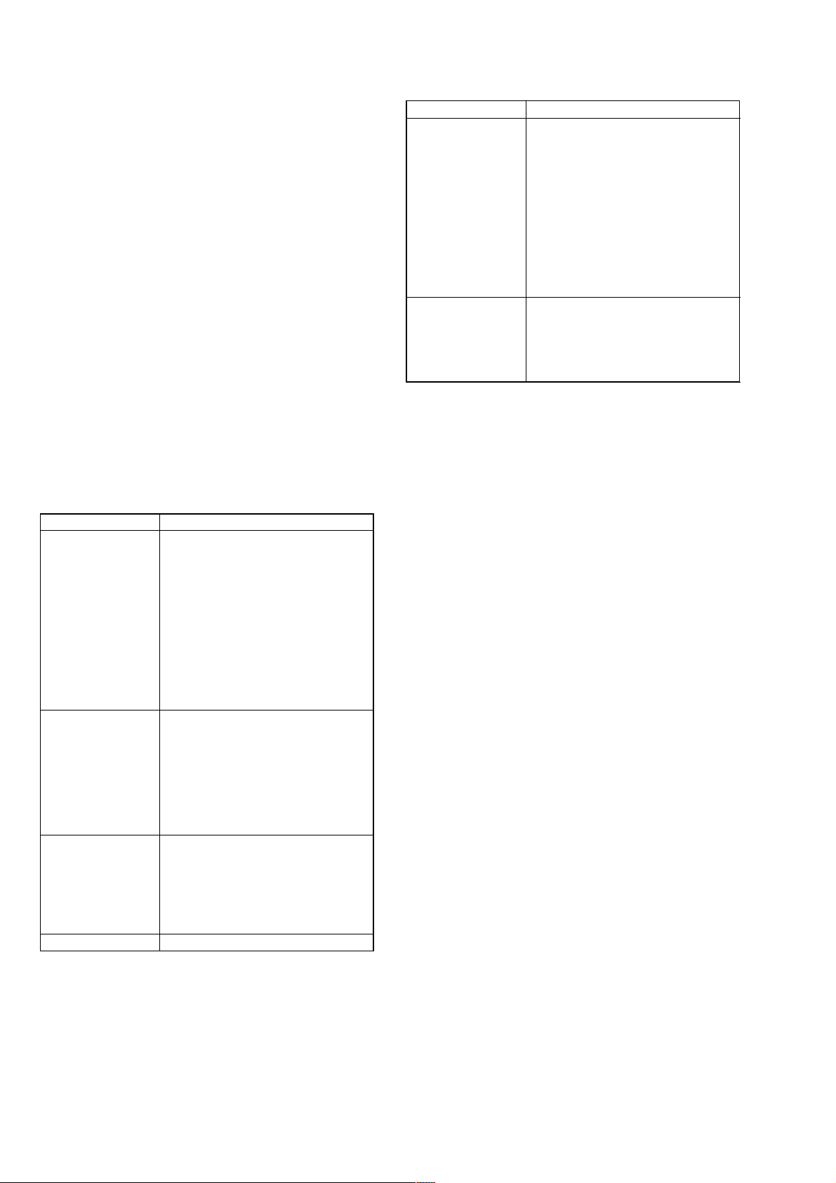
Measurement items and specifications
Measurement item Description Specifications (unit: second)
RL Time required for the table to make one complete rotation. 6.0 to 7.5
(R: Clockwise rotation. L: Counter-clockwise rotation)
CLOSE Time required to close the tray. <2.3
BU UP Time required for the BU block to perform chucking from the DOWN position <1.3
EXOPEN The XCHANGE OPEN time <2.5
EXCLOSE The EXCHANGE CLOSE time <2.8
BU DOWN Time required for the BU block to perform unchucking and going to the DOWN <0.9
position
OPEN Time required to open the tray <2.4
25

SCD-CE775
5-6 . AGING MODE
(• Perform as necessary)
5-6-1. The aging can be performed to the set in the test
mode.
The aging can be continued by the set number of times or until an
error occurs.
In the aging, the following operations are repeated.
Ta ble turntDisc chuckingtDisc detecttServo ontAuto
adjustmenttTOC readingtPlay of first track for 5 secondtPlay
of last track for 5 secondtPlay of first track for 5 secondtDisc
unchucking
Setting Method:
1. After setting the test mode, rotate the [ AMS ] dial to
select “94. SET AGING” and press the [ AMS ] dial
lL
lL
to enter.
2. When “A GING TIMES” is displayed, rotate the [ AMS ]
lL
dial to set the number of aging times. (For the number of times,
every 10 times can be set. Setting 0 (zero) eliminates the count
limitation where the aging is repeated until an error occurs)
Note: Do not perform unmanned overnight aging..
3. Press the [ AMS ] dial, and “AGING START” will be
lL
displayed instantaneously, then “DISC IN & JOG ON” will be
displayed and the tray will come out automatically.
4. Place a disc (CD or the SACD SL disc) on the tray . In the case
of SCD-CE775, the multiple discs can be placed. Even when
the discs (CD or the SACD SL disc) of different types are
mixed, the aging test can be performed. Use the [DISC SKIP]
key when placing a disc. When discs are placed in positions,
turn the [ AMS ] dial.
lL
5. The aging test starts.
6. At the completion of aging by the set number of times, the
tray will come out automatically and the check will stop.
Typical time required for aging About 1 hour/100 times
“AGING SUCCESS!” will be displayed if no error occurred
in the aging, or the error will be displayed if an error occurred.
(Refer to the following error list)
5-6-2. Aging Mode of the Panel Door Independently
1. Start up the unit in the normal operation mode.
2. While press the
[STOP] key , turn the [ AMS ] dial and
lL
then press the [CONTINUE] key. (The prog ram does not advance if these keys are not pressed in the above sequence.)
3. The panel door repeats opening and closing.
4. The messages “AP-B 000000” (during open) t “AP-C
000000” (during close) are repeated on the FL display. Number of times of open/close are displayed in decimal number in
“000000” with OPEN/CLOSE as a set.
5. Press the [STOP] key to terminate the aging mode and to return to the normal mode.
5-7. SHIPPING MODE
The repaired set must be initialized, and for this purpose the set
should be set to the shipping mode.
Setting Method:
1. After setting the test mode, rotate the [ AMS ] dial to
select “8d Set Up Init” and press the [ AMS ] dial to
lL
lL
enter.
2. “8D 000000000 00” will be displayed, and if the scroll starts
in the left direction, the set initialization has completed
3. Press the [POWER] button to turn the power off.
Note: Take care not to leave the test disc in the set.
The following setups are established in the SHIPPING MODE
1. Initialization of EEPROM (IC903)
• PLAY MODE ALL DISCS, CONTINUE
• COMMAND MODE CD1
• LAYER SELECTSACD
• M/2CH SELECT MULTI
• DIGITAL FILTER STD
• 2ch SPK MODE 2ch DIRECT
• Mch SPK MODEMch DIRECT
• Resetting the accumulated hours meter.
2. Chucking at the DISC1 position.
Error List
An error occurring during the check in the aging mode of the test mode is displayed automatically (scroll display) immediately when the
error occurred.
< How to view the error history >
1. Select “95 DISP ERROR” with the [ AMS ] key, and press the [ AMS ] key once.
lL lL
2. The error that has occurred lastly in the set and the signal status (H = 1, L = 0) at that time are displayed on the FL display by scrolling.
(Types of the errors and the signal status that can be checked, are the same as the error display of the aging mode.)
3. Press the [ AMS ] key once again to show the error history repeatedly.
lL
4. When the error history is displayed with scrolling once, the mode returns to the normal test mode.
26
SCD-CE775
Error display is as follows.
Error name, Disc type, IN SW (Sled in switch state), FOK (FOK signal state), LOCK (LOCK signal state), From (Displayed if effective),
To (Displayed if effective), Aging times (Displayed in aging mode only)
Display example
ACCESS MOVE ERROR : SACDSL : IN SW 1 FOK 0 LOCK 0 : FROM 205663 : TO 2461601 : TIMES 5
(Error name) (Disc type) (Sled in switch, FOK, LOCK signal state) (Relative address) (Relative address)(Aging times)
Display Items List:
Display items Description Remarks
Error name tRefer to the error display list
IN SW Sled in switch state when an error occurred
FOK FOK signal state when an error occurred
LOCK LOCK signal state when an error occurred.
From Displayed if effective in the error item Disc PSN (relative address) is
To Displayed if effective in the error item Disc PSN (relative address) is
0: switch off Not limit in
1: switch on Limit in (Optical pick-up is at most inward track)
FOK signal Is focus on?
0: FOK L (Focus off), 1: FOK H (Focus on)
LOCK signal Is PLL lock?
0: LOCK L Not lock, 1: LOCK H Lock
tRefer to the error display list displayed in case of access error
tRefer to the error display list displayed in case of access error
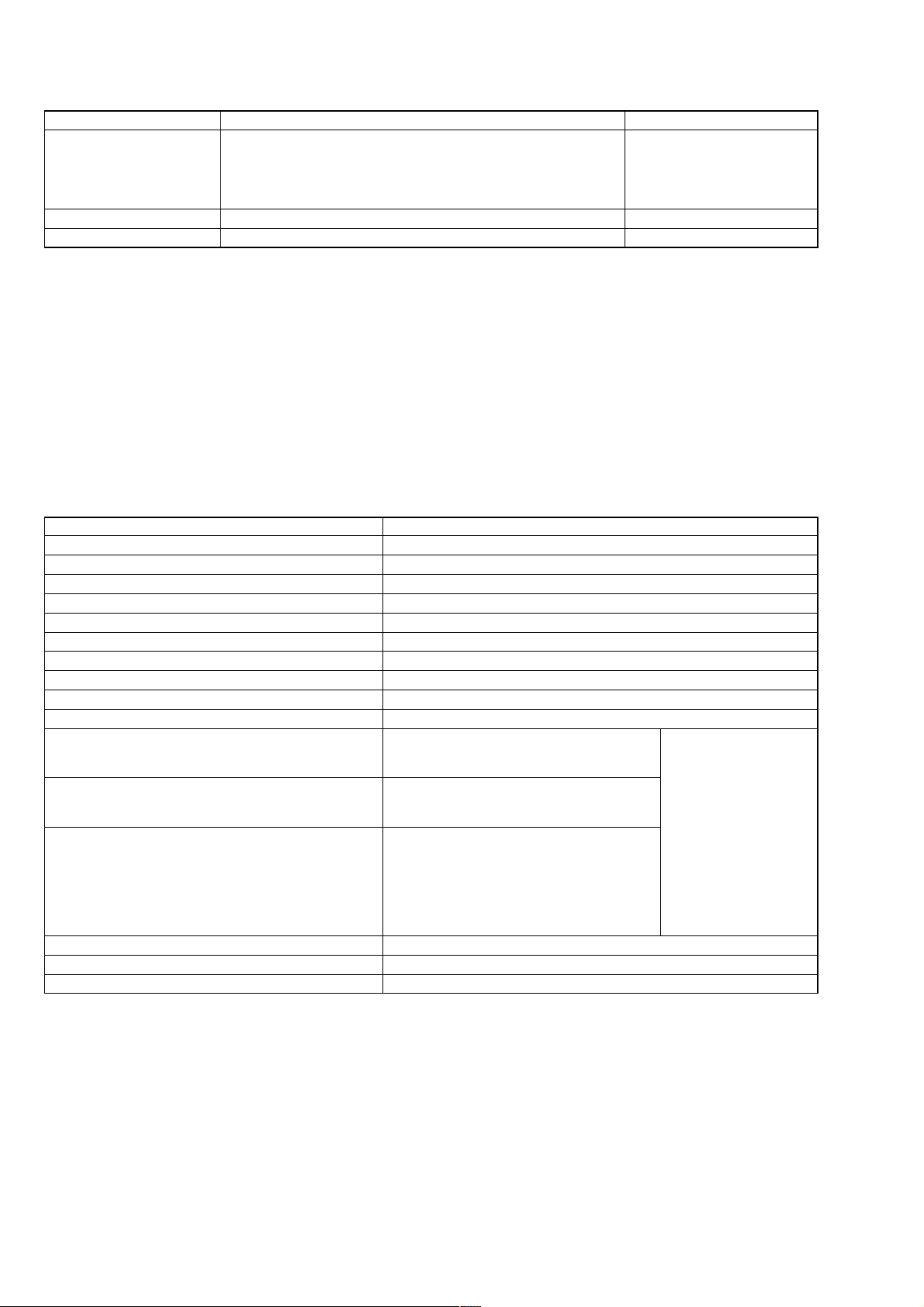
Error Display List:
Error display Error description Main causes of errors
DISC DETECT ERROR Disc type error Optical pick-up, RF amplifier or CD
OFFSET ADJUST ERROR Offset adjustment error Optical pick-up, RF amplifier or CD
FCS SRV ON ERROR Focus servo error From:1 means focus search failed
CLV SRV ON ERROR CLV servo error Defocusing
E-F BALANCE ERROR E-F balance adjustment error Defocusing
TRK SRV ON ERROR Tracking servo error Tracking servo on time out
SLD SRV ON ERROR Sled servo error Sled servo on time out
FOCUS BIAS ERROR Focus bias adjustment failed Defocusing during adjustment
FCS AGC ERROR Error at focus gain automatic adjustment Defocusing during adjustment
TRK AGC ERROR Error at tracking gain automatic adjustment Defocusing during adjustment
ACCESS 1TJ ERROR Access Error at one-track jump Access failed
ACCESS FINE ERROR Access Error at fine search Access failed
ACCESS MOVE ERROR Access Error at M-track MOVE Access failed
WHILE PLAYING ERROR Error during disc playing Defocusing
FCS JUMP ERROR Time out error at focus jump Defocusing
MIRR measured time is displayed in From: DSP IC is faulty
DSP IC is faulty
An error code is displayed in From: From:2 means defocusing
Optical pick-up, RF amplifier or CD
DSP IC is faulty
An error code is displayed in From: Description of display
An error code is displayed in From
From:1 means retry failed 3 times
From:2 means abnormal value
Optical pick-up, RF amplifier or CD
DSP IC is faulty
Optical pick-up, RF amplifier or CD
DSP IC is faulty
Optical pick-up, RF amplifier or CD
DSP IC is faulty
Effective addresses (PSN) are displayed in From: and To: Defocusing at access, etc
Effective addresses (PSN) are displayed in From: and To: Defocusing at access, etc
Effective addresses (PSN) are displayed in From: and To: Defocusing at access, etc
Focusing retry failed
Focusing retry failed
System errors are as follows.
Note: This error is not saved in the set.
Display Description
Toc Error * Error during the time from auto adjustment to TOC reading, Different type of disc (Such as a DVD disc), Disc is dirty
Toc Error **** Illegal SACD (Such as a pirated version)
Read Error Music data read error (Error during disc playing)
27

SCD-CE775
e
5-8. WAVEFORMS CHECK
This set performs automatic adjustment for each disc, and therefore the set need not be adjusted when parts are replaced, but it
requires checking following the description in this section, 5-1.
IC AND FLUORESCENT DISPLAY TUBE CHECK and 5-2.
AUTO CHECK.
For the check, the test mode is used. Wrong setting causes a trouble,
thus requiring extreme care.
BU Electrical Adjustment Mode
The BU electrical adjustment mode is used to check the S curve
waveform, traverse waveform and RF waveform. After a disc is
lL
placed on the tray, each time the
[ AMS ] dial is pressed,
the check mode is switched in order for S curve waveformt
traverse waveformtRF waveform.
Setting Method:
After setting the test mode, rotate the [ AMS ] dial to select
“9C BU DENCHO” and press the [ AMS ] dial to enter.
lL
lL
“BU MEASURE” will be displayed if the BU electrical adjustment mode becomes active.
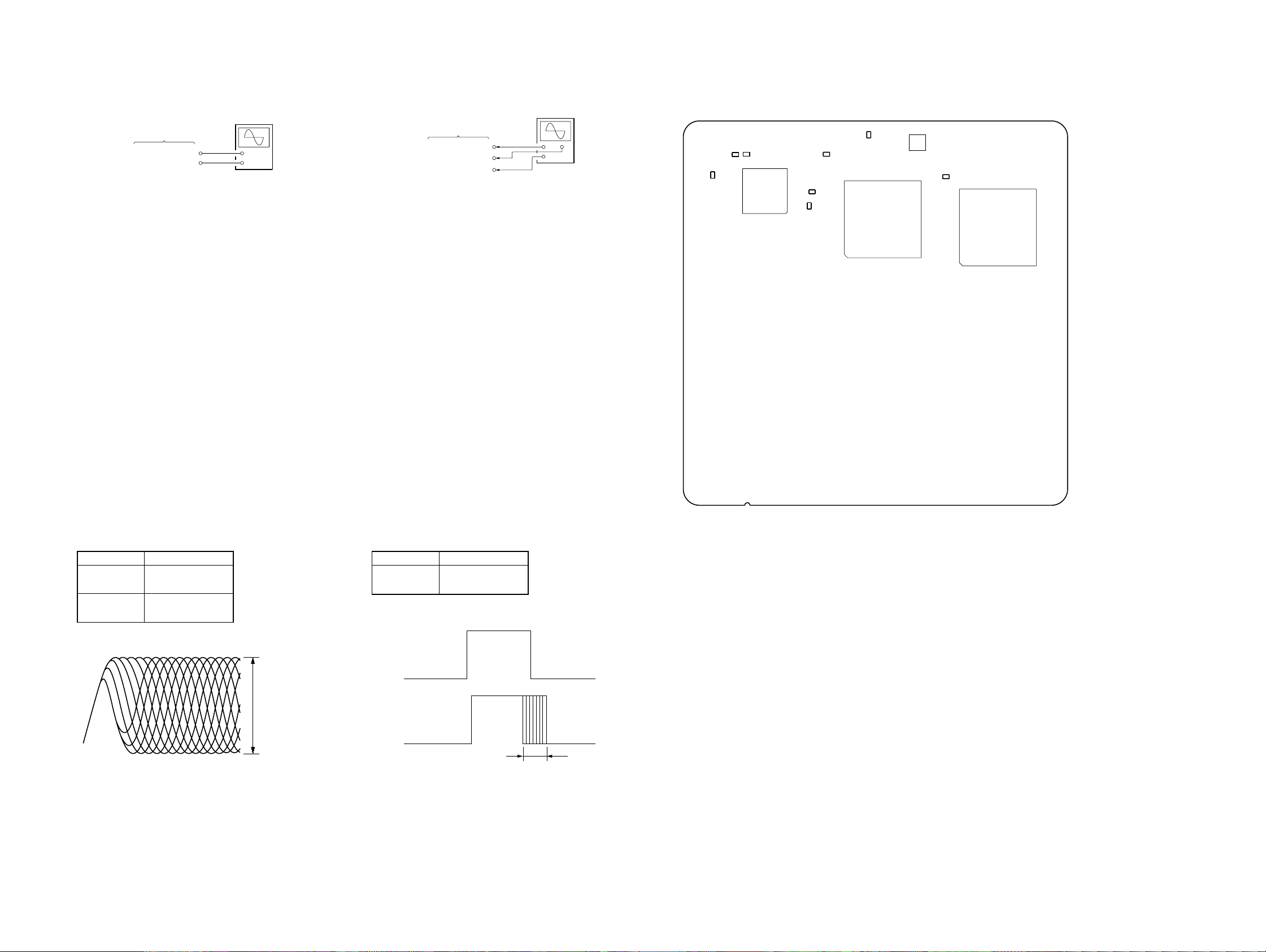
S Curve Check
Connection:
oscilloscop
MAIN board
TP506 (FE)
TP504 (AVC)
+
–
Checking Method:
1. After setting the BU electrical adjustment, place the test disc
(PATD-012 or SATD-S5 or SATD-S4) on the tray and close
[ AMS ] dial.
the tray, then press the
lL
2. At the completion of disc type check, “CD DETECT” will be
displayed (for PATD-012 or YEDS-18).
Note: For the SA TD-S5 or SATD-S4, “SACD DETECT“ is displayed.
3. Press again the [ A MS ] dial, and the S curve wav eform
l
L
check mode will become active and “S-CURVE MODE” will
be displayed.
4. Connect an oscilloscope to the TP506 (FE) and TP504 (AVC)
on the MAIN board.
5. Check that the level A and B of w aveform on the oscilloscope
satisfy the specification.
Traverse Check
Connection:
oscilloscope
MAIN board
TP513 (TE)
TP504 (AVC)
+
–
Checking Method:
1. Under the condition of S curve waveform check mode in step
5, press the [ AMS ] dial.
lL
2. After “WAIT” is displayed, the traverse waveform c heck mode
will become active and “TRAVERSE MODE” will be displayed.
3. Connect an oscilloscope to the TP513 (TE) and TP504 (AVC)
on the MAIN board.
4. Check that the level A and B of waveform on the oscilloscope satisfy the specification.
Specified Value:
Disc AB
SATD-S5 or
SATD-S4
PATD-012 or
YEDS-18
Traverse waveform
VC
0.6 to 1.6 Vp-p
- 0.1 to +0.1V
0.5 to 1.3 Vp-p
Center fo the waveform
A
B
Checking and Connecting Location : See page 29.
Specified Value:
Disc AB
SATD-S5 or
SATD-S4
PATD-012 or
YEDS-18
S curve waveform
VC
Note: For easier observation of this waveform, extend the sweep time
and raise the brightness.
0.7 to 1.7 Vp-p - 0.1 to +0.1V
A
B
Checking and Connecting Location : See page 29.
28
SCD-CE775
V
e
RF Level Check
Connection:
oscilloscope
MAIN board
TP703 (RFAC)
TP704 (AGND)
+
–
Checking Method:
1. Under the condition of traverse waveform check mode in step
4, press the [ AMS ] dial.
lL
2. Connect an oscilloscope to the TP703 (RFAC) and TP704
(AGND) on the MAIN board.
3. After “WAIT” is displayed, the RF waveform check mode will
become active and “PLAY 5th TRACK” will be displayed,
and the 5th music on the disc will be played.
4. Check that the RF waveform is clear and the level satisf ies the
specification.
5. Press the [ AMS ] dial, and “OUTSIDE TRA CK” will be
lL
displayed and the outward track of the disc will be played.
6. Check that the RF waveform is clear and the level satisf ies the
specification.
7. Press the [ AMS ] dial, and “INSIDE TRACK” will be
lL
displayed and the inward track of the disc will be played.
8. Check that the RF waveform is clear and the level satisf ies the
specification.
9. After checking, press the [ AMS ] dial, and the test is
lL
over when “BU MEASURE” is displayed.
10. Press the [ OPEN/CLOSE] button to open the tray, and re-
A
move the test disc.
11. Using each type of disc, repeat from step 1 of S curve waveform check up to step 10 of RF level check.
12. When the check is over, press the
[POWER] button to turn the
power off.
Note: Take care not to leave the test disc in the set.
CLV Jitter Check (CD only)
Connection:
oscilloscop
MAIN board
TP516 (RFCK)
TP517(WFCK)
TP808 (DG)
(CH1)
(CH2)
+
+
–
Checking Method:
1. Set the test mode.
2. Connect an oscilloscope to the TP516 (RFCK) (CH1), TP517
(WFCK) (CH2) and TP808 (DG) (GND) on the MAIN board.
3. Place the test disc PATD-012 or YEDS-18 on the tray, and
close the tray.
4. Rotate the [ AMS ] dial to select “61 DISC DETECT”,
and press the [ AMS ] dial to enter. Then, the disc type
lL
lL
will be judged.
5. Check that the disc type has been judged.
(For the P ATD-012, “DSKMOD CD” will be displayed. Refer
to the test mode, DISC DETECT command (page 55))
6. Rotate the [ AMS ] dial to select “86 ALL SRV ON”,
and press the [ AMS ] dial. Then, the disc will rotate,
lL
lL
automatic adjustment will be carried out, and all servos will
be turned on.
7. Rotate the [ AMS ] dial to select “07 DSP MON3”, and
press the [ AMS ] dial to enter.
l
lL
L
8. Check that the value A of waveform on the oscilloscope satisfies the specification.
9. Rotate the [ AMS ] dial to select “19 ALL SRV OFF”,
and press the [ AMS ] dial. Then, all servos will be
lL
lL
turned off and the disc rotation will stop.
[ OPEN/CLOSE] button to open the tray, and re-
10. Press the
A
move the test disc.
11. Press the [POWER] button to turn the power off.
Note: Take care not to leave the test disc in the set.
Checking and Connecting Location:
– MAIN Board (Component Side) –
TP704
TP506
(FE)
TP513
(TE)
TP504
(AVC)
IC509
(AGND)
TP516
(RFCK)
TP517
(WFCK)
TP703
(RFAC)
IC701
IC703
TP808
(DG)
IC801
Specified V alue:
Disc A
SATD-S5 or
SATD-S4
PATD-012 or
YEDS-18
RF signal waveform
Note: Clear RF waveform refers to the wav eform where ◊ shapes should
be distinctively observed in the center.
0.65 to 1.1 Vp-p
0.45 to 0.95 Vp-p
VOLT/DIV: 200 m
TIME/DIV: 500 ns
A
Specified Value:
Disc A
PATD-012 or
YEDS-18
CLV jitter waveform
35 µsec or less
A
2929
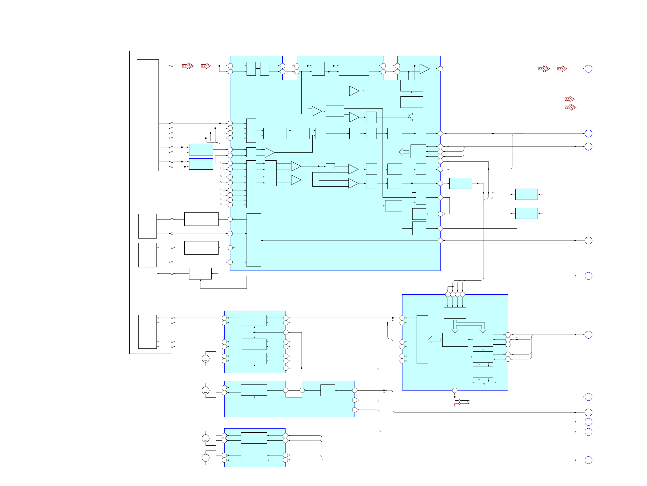
SCD-CE775
SECTION 6
DIAGRAMS
6-1. BLOCK DIAGRAM – RF/SERVO Section –
DETECTOR
OPTICAL PICK-UP
BLOCK
(KHM-230AAA)
LASER
DIODE
(FOR CD)
LASER
DIODE
(FOR SACD)
MODULE
CIRCUIT B+
CD LD
CD PD
DVD LD
DVD PD
VMOD
RF
A
B
C
D
E
F
G
H
SUMMING AMP
SUMMING AMP
VC
(+2.5V)
AUTOMATIC POWER
CONTROL (FOR CD)
AUTOMATIC POWER
CONTROL (FOR SACD)
IC004 (1/4)
IC004 (2/4)
Q003
Q001
B+ SWITCH
Q002, 005
D
CBA
A
B
C
D
A +5V
1
63
3
4
5
6
18
17
12
11
10
9
16
15
14
13
22
24
21
23
DVDRFP
RFSIN
A2
B2
C2
D2
CD E
CD F
A
B
C
D
CD A
CD B
CD C
CD D
CDLD
CDPD
DVDLD
DVDPD
MUX ATT
GCA,
EQ
GCA
MUX
DUAL
APC
ATOP
61
ATON
62
COMPARATOR MUX
VC
+
–
GCA
L. P. F.
DETECTOR
A
+
C
+
B
+
D
+
59
60
PHASE
AIP
INPUT
BIAS,
AIN
AGC
+
CLAMP&
ENVELOPE
–
LEVEL DAC
GCA
SACD/CD RF AMP,
FOCUS/TRACKING ERROR AMP
PROGRAMMABLE
DIFFERENTIATOR
IC001
EQ FILTER
+
–
L. P. F.
+
–
+
+
55
OFFSET
CANCEL
OFFSET
CANCEL
OFFSET
CANCEL
BOTTOM
ENVELOPE
DIP
DIN
FULL WAVE
RECTIFER
AGC
CHARGE PUMP
SERIAL
PORT
REGISTER
INPUT
BUFFER
BOTTOM
FNP
535254
FNN
AGCO
SEL
SUB GCA
L. P. F.
L. P. F.
AGCO
GCA
MUX
PEAK/
HOLD
RFAC
SDATA
SCLK
SDEN
MEVO
MIN
MIRR
LDON
57
RFAC
1
(Page 31)
• SIGNAL PATH
: SACD PLAY
: CD PLAY
TE
39
SDATA, SCLK, SDEN
A+3.3V
D+5V
FE
PI
47
46
48
42MNTR
40
38
32
31
27
26
SDATA
SCLK
SDEN
PI ERROR AMP
IC004 (3/4)
PI
FE
TE
FE/PI
FE
PIFETE
AVC
(+1.65V)
DRVC
(+2.5V)
AVC BUFFER
IC004 (4/4)
DRVC BUFFER
IC503
TE, FE
LDON
VMOD
2
3
4
5
(Page 32)
(Page 32)
(Page 31)
(Page 32)
2AXIS
DEVICE
FOCUS/
TRACKING
COIL
FCS+
FCS–
TRK+
TRK–
M2
(SLED)
M3
(SPINDLE)
M10
(LOADING)
M11
(TRAY)
40 41 39 43
FOCUS/TRACKING COIL DRIVER,
SLED MOTOR DRIVER
IC502
12 5
11 6
14 2
13 3
MM
MM
MM
MM
17 24
18 23
8
9
8
9
11
10
FOCUS COIL
DRIVE
TRACKING COIL
DRIVE
SLED MOTOR
DRIVE
SPINDLE MOTOR
DRIVE
LOADING/TRAY MOTOR DRIVE
OUT1+
OUT1–
OUT2+
OUT2–
IC11
LOADING MOTOR
DRIVE
TRAY MOTOR
DRIVE
STBY1
9
STBY2
20
15 16 17
SPINDLE MOTOR DRIVE
IC512
FIN1
2
RIN1
RIN2
FIN2
3
16
17
LOAD OUT
BUFFER
LOAD IN
TBLL
TBLR
MUTE2
MUTE1
13
MUTE LOAD
2
MUTE 2D
SP ON
SPDA
FJMP2
FJMP1
FFDR
33
FRDR
34
TFDR
31
TRDR
32
SFDR
29
SRDR
30
DIGITAL SERVO
PROCESSOR
IC509 (1/2)
PWM GENERATOR
FOCUS/TRACKING/SLED
FE
TE
SE
RFDC
A/D
CONVERTER
FOCUS
TRACKING/SLED
SERVO DSP
SSTP
26
D+3.3V
DFCT, FOK
DETECTOR
SERVO
INTERFACE
SERVO AUTO
SEQUENCER
TO CPU INTERFACE
S1
(LIMIT)
FOK
MIRR
DFCT
COUT
SCLK
FOK, MIRR,
FOK
22
MIRR
20
21
COUT
19
SCLK
8
MUTE 2D, SP ON, MUTE LOAD
COUT, SCLK
LIM SW
SPDA, FJMP1/2
SPIN
LOAD I/O, TBLL, TBLR
10
11
6
7
8
9
(Page 32)
(Page 32)
(Page 31)
(Page 31)
(Page 32)
(Page 32)
3030
 Loading...