

SA-VE322/VE325/WMS325/
SS-CN325/V325
SERVICE MANUAL
Ver 1.1 2001.07
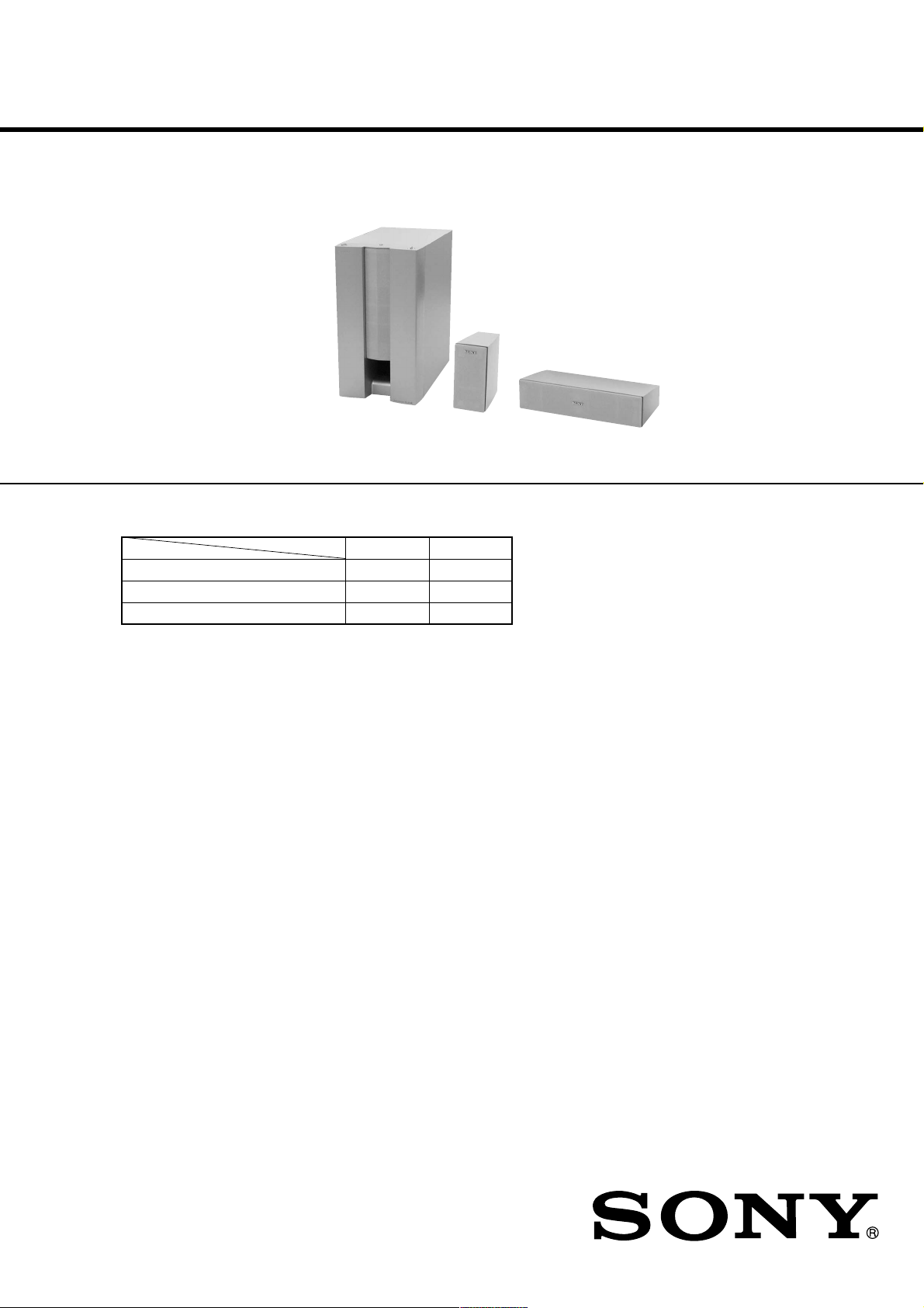
SA-WMS325
• SA-VE322/VE325 consists of the following models respectively.
SA-VE322 SA-VE325
Active Subwoofer (SA-WMS325) aa
Center Speaker (SS-CN325) – a
Front and Rear Speakers (SS-V325) aa
SS-V325
US Model
Canadian Model
E Model
Australian Model
Chinese Model
SA-VE325
AEP Model
UK Model
SA-VE322/VE325
SS-CN325
SS-V325 (front and rear speakers)
Speaker system Full range,
Speaker units 5.5 × 11 cm (
Enclosure type Bass reflex
Rated impedance 8 ohms
Power handling capacity
Maximum input power: 100 watts
Sensitivity level 87 dB (1 W, 1 m)
Frequency range 90 Hz - 20,000 Hz
Dimensions (w/h/d) Approx. 70 × 152 × 126
Mass Approx. 830 g (18 lb 5
SS-CN325 (center speaker)
Speaker system Full range × 2,
Speaker units 5.5 × 11 cm (
Enclosure type Bass reflex
Rated impedance 8 ohms
Power handling capacity
Maximum input power: 120 watts
Sensitivity level 89 dB (1 W, 1 m)
Frequency range 90 Hz - 20,000 Hz
Dimensions (w/h/d) Approx. 300 78
Mass Approx. 1600 g (35 lb 4
magnetically shielded
in.), cone type
mm (2
including front grille
oz) each
magnetically shielded
in.), cone type
126 mm (11
5 in.), including front
grille
oz)
7
/
7
/
× 6 × 5 in.),
8
7
/
7
/
32
32
× 3
8
7
×
/
7
×
/
1
16
16
/
SPECIFICATIONS
SA-WMS325 (subwoofer)
Speaker system Active subwoofer,
Speaker unit Woofer: 16 cm (6
Enclosure type Advanced SAW type
Reproduction frequency range
Amplifier section
Continuous RMS power output
Inputs
LINE IN (input pin jack)
SPEAKER IN (input terminals)
Outputs
LINE OUT (output pin jack)
SPEAKER OUT (output terminals)
General
Power requirements
North American model: 120 V AC, 60 Hz
European model: 220 - 230 V AC, 50/60 Hz
Other models: 110 - 120 V/220-240 V
Power consumptions 70 W
×
8
Dimensions (w/h/d)
Mass Approx. 10.3 kg
magnetically shielded
cone type
28 Hz - 200 Hz
75 W (8 ohms, 20 Hz 20 kHz, 0.8% THD)
AC, 50/60 Hz
1 W (standby mode)
Approx. 205 × 385 × 389
mm (8
in.), including front grille
(22 lb 11 oz)
3
/8 in.),
1
/8 × 151/4 ×15 3/
Supplied accessories
SA-VE325
Foot pads (20)
Audio connecting cord (1)
Speaker connecting cords, 10 m (32 ft 9
Speaker connecting cords, 3.5 m (11 ft 6 in.) (3)
Speaker connecting cords, 2.5 m (8 ft 2
SA-VE322
Foot pads (8)
Audio connecting cord (1)
Speaker connecting cords, 3.5 m (11 ft 6 in.) (2)
Speaker connecting cords, 2.5 m (8 ft 2
Design and specifications are subject to change without
notice.
4
3
/4 in.) (2)
1
/2 in.) (2)
1
/2 in.) (2)
9-929-572-12 Sony Corporation
2001G0500-1 Home Audio Company
C 2001.7 Shinagawa Tec Service Manual Production Group
MICRO SATELLITE SYSTEM
SA-VE322/VE325/WMS325/SS-CN325/V325
r
SAFETY CHECK-OUT
After correcting the original service problem, perform the following safety check before releasing the set to the customer:
Check the antenna terminals, metal trim, “metallized” knobs,
screws, and all other exposed metal parts for AC leakage.
Check leakage as described below.
LEAKAGE TEST
The AC leakage from any exposed metal part to earth ground and
from all exposed metal parts to any exposed metal part having a
return to chassis, must not exceed 0.5 mA (500 microamperes.).
Leakage current can be measured by any one of three methods.
1. A commercial leakage tester, such as the Simpson 229 or RCA
WT -540A. Follo w the manufacturers’ instructions to use these
instruments.
2. A battery-operated AC milliammeter. The Data Precision 245
digital multimeter is suitable for this job.
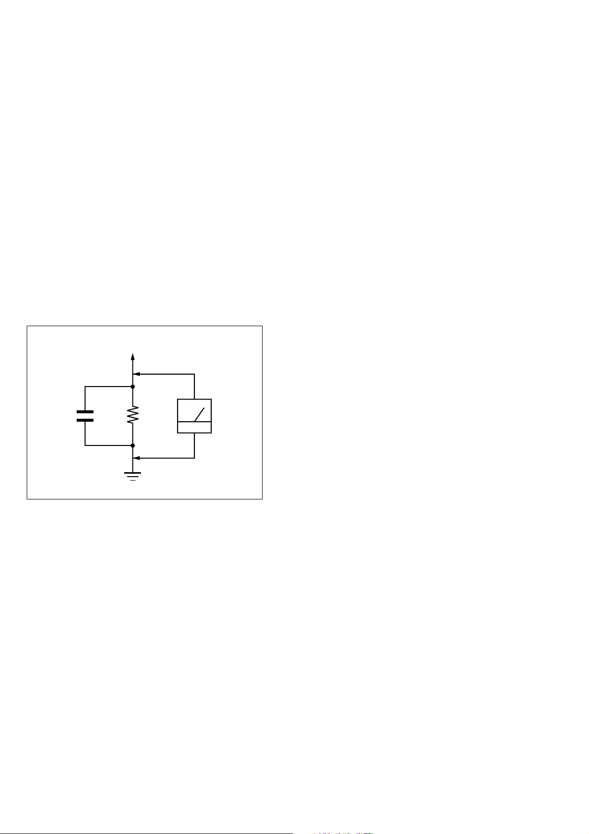
3. Measuring the voltage drop across a resistor by means of a V OM
or battery-operated A C voltmeter . The “limit” indication is 0.75
V, so analog meters must have an accurate low-voltage scale.
The Simpson 250 and Sanwa SH-63Trd are examples of a passive VOM that is suitable. Nearly all battery operated digital
multimeters that have a 2 V A C range are suitable. (See Fig. A)
To Exposed Metal
Parts on Set
AC
1.5 k
0.15 µF
Fig. A. Using an AC voltmeter to check AC leakage.
Ω
Earth Ground
voltmete
(0.75 V)
SAFETY-RELATED COMPONENT WARNING!!
COMPONENTS IDENTIFIED BY MARK 0 OR DOTTED
LINE WITH MARK 0 ON THE SCHEMATIC DIAGRAMS
AND IN THE PARTS LIST ARE CRITICAL TO SAFE
OPERATION. REPLACE THESE COMPONENTS WITH
SONY PARTS WHOSE PART NUMBERS APPEAR AS
SHOWN IN THIS MANUAL OR IN SUPPLEMENTS PUBLISHED BY SONY.
2
ATTENTION AU COMPOSANT AYANT RAPPORT
À LA SÉCURITÉ!
LES COMPOSANTS IDENTIFIÉS P AR UNE MARQUE 0
SUR LES DIAGRAMMES SCHÉMATIQUES ET LA LISTE
DES PIÈCES SONT CRITIQUES POUR LA SÉCURITÉ
DE FONCTIONNEMENT. NE REMPLACER CES COMPOSANTS QUE PAR DES PIÈCES SONY DONT LES
NUMÉROS SONT DONNÉS DANS CE MANUEL OU
DANS LES SUPPLÉMENTS PUBLIÉS PAR SONY.
SA-VE322/VE325/WMS325/SS-CN325/V325
SECTION 1
DIAGRAMS
1-1. NOTE FOR PRINTED WIRING BOARDS AND SCHEMATIC DIAGRAMS
Note on Printed Wiring Board:
• : Pattern from the side which enables seeing.
• Abbreviation
AR : Argentina model
SP : Singapore model
Note on Schematic Diagram:
• All capacitors are in µF unless otherwise noted. pF: µµF
50 WV or less are not indicated except for electrolytics
and tantalums.
• All resistors are in Ω and 1/
specified.
• 2 : nonflammable resistor.
• C : panel designation.
Note:
The components identified by mark 0 or dotted
line with mark 0 are critical for safety.
Replace only with part
number specified.
• A : B+ Line.
• B : B– Line.
• Voltages are dc with respect to ground under no-signal
conditions.
• Voltages are dc with respect to ground in service mode.
no mark : MUSIC MODE
( ) : MOVIE MODE
• Voltages are taken with a V OM (Input impedance 10 MΩ).
Voltage var iations may be noted due to normal production tolerances.
• Signal path.
F : AUDIO
• Abbreviation
AR : Argentina model
AUS : Australian model
CH : Chinese model
CND : Canadian model
MX : Mexican model
SP : Singapore model
4
W or less unless otherwise
Note:
Les composants identifiés par
une marque 0 sont critiques
pour la sécurité.
Ne les remplacer que par une
pièce portant le numéro
spécifié.
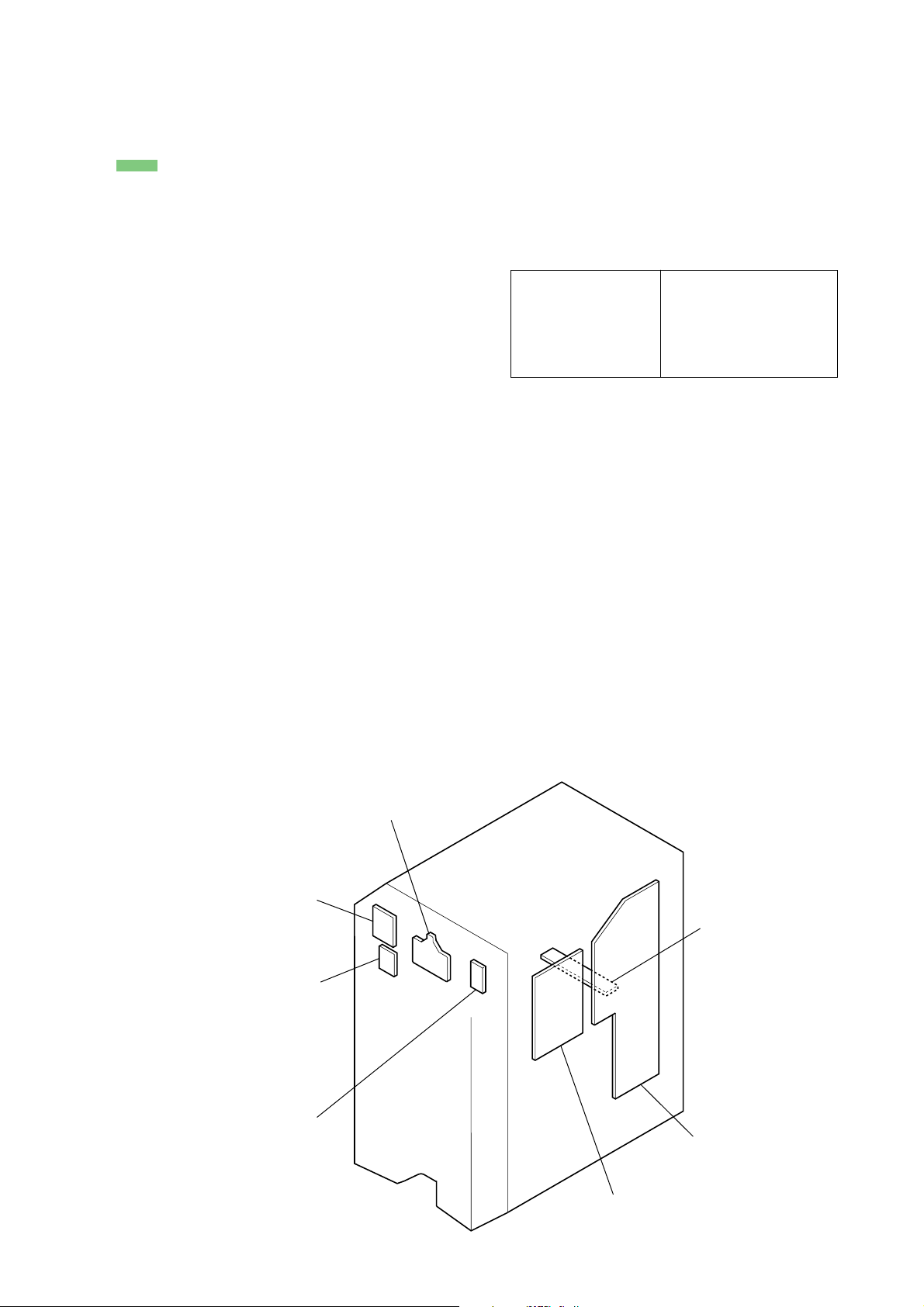
• Circuit Boards Location
(SA-WMS325)
CONTROL board
CONNECTOR board
MODE board
POWER SWITCH board
POWER board
MAIN board
AUTO POWER board
3
SA-VE322/VE325/WMS325/SS-CN325/V325
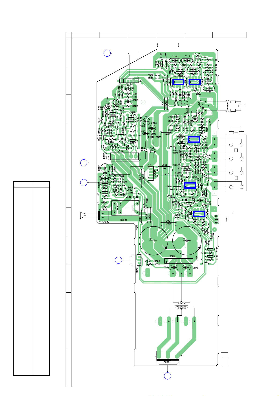
1-2. PRINTED WIRING BOARD – MAIN Section (SA-WMS325) –
• See page 3 for Circuit Boards Location.
1 2 3 4 5 6
A
A
CONNECTOR BOARD
CN202
(Page 7)
MAIN BOARD
• Semiconductor
Location
Ref. No. Location
D101 E-5
D102 E-5
D103 D-5
D104 D-5
D301 B-2
D302 B-2
D303 D-2
D304 D-2
D305 F-4
D306 H-3
D501 H-4
D502 D-3
D503 D-3
D701 F-5
D702 F-5
D703 F-4
D704 G-4
IC101 D-5
IC102 B-5
IC103 B-4
IC104 F-5
IC701 G-5
B
IC102
IC103
J101
IN
OUT
OUT
+
TM101
SPEAKER
L
LINE
IN
+
C
D
IC101
––
E
F
G
B
POWER BOARD
CN401
(Page 7)
C
AUTO POWER
BOARD
CN605
(Page 8)
SP1
IC104
IC701
S701
POWER SAVE
AUTO
OFF
––
R
+
+
H
D
POWER SWITCH
BOARD
CN801
I
(Page 8)
Q101 B-5
Q102 A-5
Q103 A-4
Q104 A-4
Q301 D-2
Q302 C-2
Q303 C-2
Q304 C-3
Q305 C-3
Q306 D-2
Q307 D-3
Q308 F-2
Q309 E-2
Q310 F-2
Q311 F-2
Q701 F-5
Q702 F-5
Q703 H-5
Q704 H-5
Q705 H-5
4
T501
J
POWER
TRANSFORMER
K
11
1-680-777-
(11)
L
(Page 8)
E
AUTO POWER
BOARD
CN604
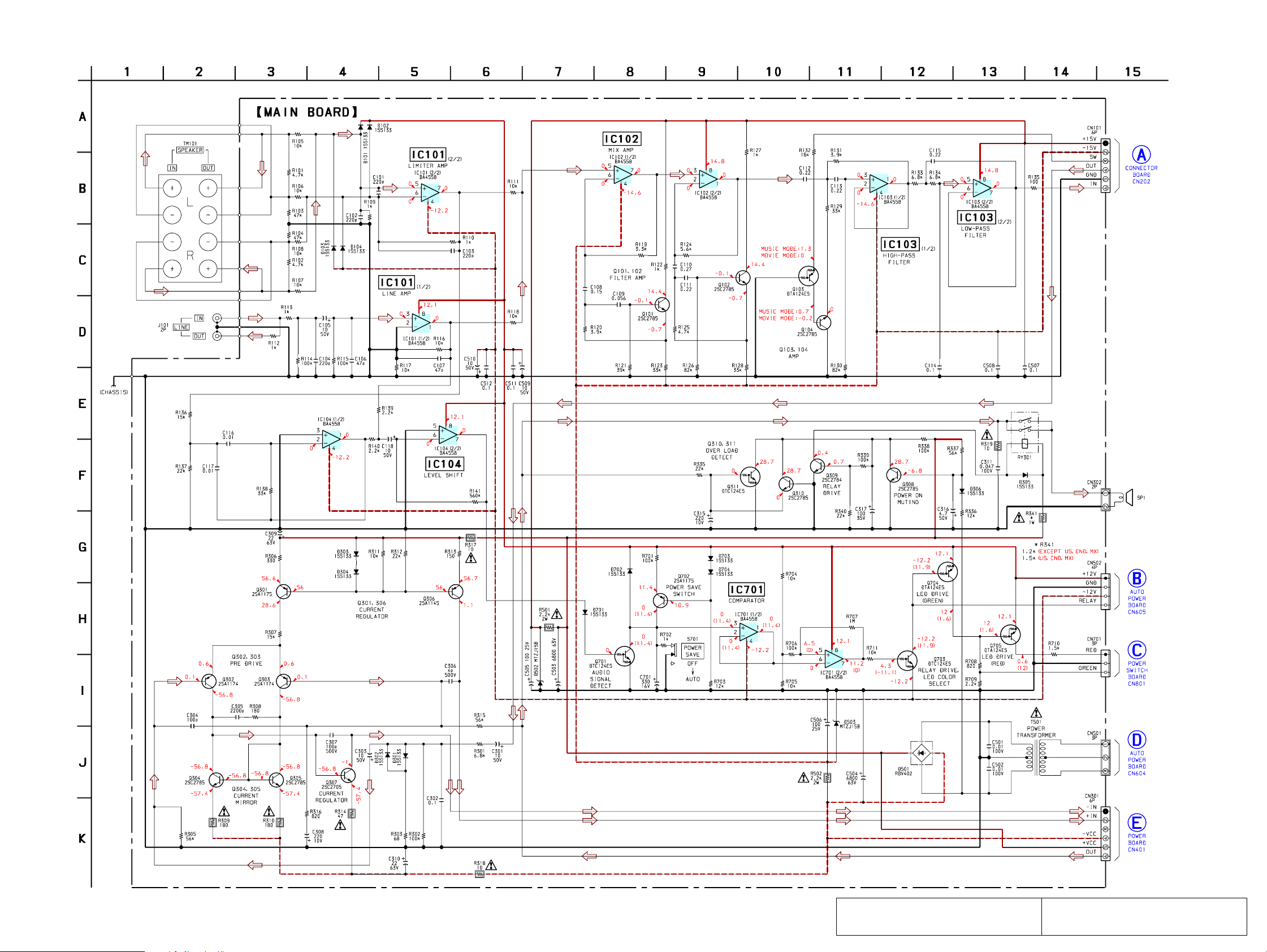
1-3. SCHEMATIC DIAGRAM – MAIN Section (SA-WMS325) –
SA-VE322/VE325/WMS325/SS-CN325/V325
(Page 6)
(Page 9)
(Page 9)
(Page 9)
(Page 6)
The components identified by mark 0 or dotted
line with mark 0 are critical for safety.
55
Replace only with part number specified.
Les composants identifiés par une marque 0 sont
critiques pour la sécurité. Ne les remplacer que
par une pièce portant le numéro spécifié.
 Loading...