

Sony VPL-CX85, RM-PJM17, RM-PJP1 Service Manual

DATA PROJECTOR
VPL-CX85
REMOTE CONTROLLER
RM-PJP1
RM-PJM17
SERVICE MANUAL
1st Edition

! WARNING
This manual is intended for qualified service personnel only.
To reduce the risk of electric shock, fire or injury, do not perform any servicing other than that
contained in the operating instructions unless you are qualified to do so. Refer all servicing to
qualified service personnel.
! WARNUNG
Die Anleitung ist nur für qualifiziertes Fachpersonal bestimmt.
Alle Wartungsarbeiten dürfen nur von qualifiziertem Fachpersonal ausgeführt werden. Um die
Gefahr eines elektrischen Schlages, Feuergefahr und Verletzungen zu vermeiden, sind bei
Wartungsarbeiten strikt die Angaben in der Anleitung zu befolgen. Andere als die angegeben
Wartungsarbeiten dürfen nur von Personen ausgeführt werden, die eine spezielle Befähigung
dazu besitzen.
! AVERTISSEMENT
Ce manual est destiné uniquement aux personnes compétentes en charge de l’entretien. Afin
de réduire les risques de décharge électrique, d’incendie ou de blessure n’effectuer que les
réparations indiquées dans le mode d’emploi à moins d’être qualifié pour en effectuer d’autres.
Pour toute réparation faire appel à une personne compétente uniquement.
WARNING!!
AN INSULATED TRANSFORMER SHOULD BE USED DURING
ANY SERVICE TO AVOID POSSIBLE SHOCK HAZARD, BECAUSE OF LIVE CHASSIS.
THE CHASSIS OF THIS RECEIVER IS DIRECTLY CONNECTED
TO THE AC POWER LINE.
SAFETY-RELATED COMPONENT WARNING !!
COMPONENTS IDENTIFIED BY A
DIAGRAMS, EXPLODED VIEWS AND IN THE PARTS LIST ARE
CRITICAL TO SAFE OPERATION. REPLACE THESE COMPONENTS WITH SONY PARTS WHOSE P ART NUMBERS APPEAR
AS SHOWN IN THIS MANUAL OR IN SUPPLEMENTS PUBLISHED BY SONY . CIRCUIT ADJUSTMENTS THAT ARE CRITICAL TO SAFE OPERATION ARE IDENTIFIED IN THIS MANU AL.
FOLLOW THESE PROCEDURES WHENEVER CRITICAL COMPONENTS ARE REPLACED OR IMPROPER OPERATION IS
SUSPECTED.
!!
! MARK ON THE SCHEMA TIC
!!
ATTENTION!!
AFIN D’ÉVITER TOUT RISQUE D’ÉLECTROCUTION
PROVENANT D’UN CHÂSSIS SOUS TENSION, UN
TRANSFORMA TEUR D’ISOLEMENT DOIT ETRE UTILISÉ LORS
DE TOUT DÉPANNA GE.
LE CHÂSSIS DE CE RÉCEPTEUR EST DIRECTEMENT
RACCORDÉ Á L’ALIMENTATION SECTEUR.
ATTENTION AUX COMPOSANTS RELATIFS Á LA
SÉCURITÉ!!
LES COMPOSANTS IDENTIFIÉS PAR UNE MAPQUE
LES SCHÉMAS DE PRINCIPE, LES VUES EXPLOSÉES ET LES
LISTES DE PIECES SONT D’UNE IMPORTANCE CRITIQUE
POUR LA SÉCURITÉ DU FONCTIONNEMENT. NE LES
REMPLACER QUE PAR DES COMPOSANTS SONY DONT LE
NUMÉRO DE PIÈCE EST INDIQUÉ DANS LE PRÉSENT MANUEL
OU DANS DES SUPPLÉMENTS PUBLIÉS PAR SONY. LES
RÉGLAGES DE CIRCUIT DONT L’IMPORT ANCE EST CRITIQUE
POUR LA SÉCURITÉ DU FONCTIONNEMENT SONT
IDENTIFIÉS DANS LE PRÉSENT MANUEL. SUIVRE CES
PROCÉDURES LORS DE CHAQUE REMPLACEMENT DE
COMPOSANTS CRITIQUES, OU LORSQU’UN MAUVAIS
FONCTIONNEMENT EST SUSPECTÉ.
!!
! SUR
!!
VPL-CX85

For the customers in the Netherlands
Voor de klanten in Nederland
Hoe u de batterijen moet verwijderen, leest u in de tekst
van deze handleiding.
Gooi de batterij niet weg maar lever deze in als klein
chemisch afval (KCA).
Für Kunden in Deutschland
Entsorgungshinweis: Bitte werfen Sie nur entladene
Batterien in die Sammelboxen beim Handel oder den
Kommunen. Entladen sind Batterien in der Regel dann,
wenn das Gerät abschaltet und signalisiert “Batterie
leer” oder nach längerer Gebrauchsdauer der Batterien
“nicht mehr einwandfrei funktioniert”. Um
sicherzugehen, kleben Sie die Batteriepole z.B. mit
einem Klebestreifen ab oder geben Sie die Batterien
einzeln in einen Plastikbeutel.
VPL-CX85
1 (P)


Table of Contents
1. Service Overview
1-1. Appearance Figure ......................................................................................1-1
1-2. Board Locations ..........................................................................................1-1
1-3. Disassembly ................................................................................................1-2
1-3-1. Top Cover................................................................................... 1-4
1-3-2. QC Board ...................................................................................1-4
1-3-3. Adjustor Unit..............................................................................1-5
1-3-4. Plate (LH)...................................................................................1-5
1-3-5. NR Board and Lamp Power Supply ........................................... 1-6
1-3-6. U Board and Speaker Assembly ................................................1-6
1-3-7. C Board ...................................................................................... 1-7
1-3-8. QA Board ...................................................................................1-7
1-3-9. Optics Block Assembly..............................................................1-8
1-3-10. V Board ......................................................................................1-9
1-3-11. GB Board ................................................................................... 1-9
1-3-12. D.C Fan (Sirocco) (72 x 75) .................................................... 1-10
1-3-13. GA Board .................................................................................1-10
1-3-14. QB Board ................................................................................. 1-11
1-3-15. H2 Board and Door (Side) .......................................................1-11
1-3-16. Extension Boards and Extension Connectors .......................... 1-12
1-3-17. Extension Boards and Extension Connectors Connection .......1-12
1-4. Writing in the USB Storage Media ...........................................................1-14
1-5. Warning on Power Connection .................................................................1-15
2. Electrical Adjustments
2-1. Preparation ..................................................................................................2-1
2-1-1. Required Equipment................................................................... 2-1
2-1-2. How to Enter the Factory Mode ................................................. 2-1
2-2. V COM Adjustment ....................................................................................2-1
2-3. Initial Values of Adjustment Items .............................................................2-2
2-4. Service Know-How ..................................................................................... 2-6
2-4-1. When the Prism Block Is Replaced............................................2-6
2-4-2. When the Board is Replaced ......................................................2-6
2-5. White Balance Adjustment ......................................................................... 2-7
2-5-1. HIGH Mode of INPUT-A ..........................................................2-7
2-5-2. LOW Mode of INPUT-A ...........................................................2-7
2-5-3. HIGH Mode of VIDEO..............................................................2-7
2-5-4. LOW Mode of VIDEO............................................................... 2-7
2-6. Memory Structure .......................................................................................2-8
3. Semiconductors................................................................................. 3-1
VPL-CX85
1

4. Spare Parts
4-1. Notes on Repair Parts..................................................................................4-1
4-2. Exploded Views ..........................................................................................4-2
4-3. Electrical Parts List .....................................................................................4-6
5. Block Diagrams
Overall ....................................................................................................................5-1
C(1/4), QA, QB ......................................................................................................5-2
C (2/4)..................................................................................................................... 5-3
C (3/4), H1, H2, L, NR, U, V .................................................................................5-4
C (4/4)..................................................................................................................... 5-5
M, QC .....................................................................................................................5-6
GA, GB...................................................................................................................5-7
6. Diagrams
6-1. Frame Schematic Diagrams ........................................................................6-2
Frame Wiring ............................................................................................6-2
6-2. Schematic Diagrams and Board Layouts ....................................................6-3
Schematic Diagrams
QA.............................................................................................................6-3
QB .............................................................................................................6-4
QC .............................................................................................................6-5
C (1/15) .....................................................................................................6-8
C (2/15) .....................................................................................................6-9
C (3/15) ...................................................................................................6-10
C (4/15) ...................................................................................................6-11
C (5/15) ...................................................................................................6-12
C (6/15) ...................................................................................................6-13
C (7/15) ...................................................................................................6-14
C (8/15) ...................................................................................................6-15
C (9/15) ...................................................................................................6-16
C (10/15) .................................................................................................6-17
C (11/15) .................................................................................................6-18
C (12/15) .................................................................................................6-19
C (13/15) .................................................................................................6-20
C (14/15) .................................................................................................6-21
C (15/15) .................................................................................................6-22
U.............................................................................................................. 6-26
V.............................................................................................................. 6-26
H1............................................................................................................ 6-27
H2............................................................................................................ 6-28
2
VPL-CX85

L ..............................................................................................................6-29
NR ...........................................................................................................6-29
M (1/3) ....................................................................................................6-31
M (2/3) ....................................................................................................6-32
M (3/3) ....................................................................................................6-34
GA...........................................................................................................6-36
GB (1/3) ..................................................................................................6-39
GB (2/3) ..................................................................................................6-40
GB (3/3) ..................................................................................................6-41
Board Layouts
QA.............................................................................................................6-3
QB .............................................................................................................6-4
QC .............................................................................................................6-5
C ................................................................................................................ 6-6
U.............................................................................................................. 6-26
V.............................................................................................................. 6-26
H1............................................................................................................ 6-27
H2............................................................................................................ 6-28
L ..............................................................................................................6-29
NR ...........................................................................................................6-29
M ............................................................................................................. 6-30
GA...........................................................................................................6-37
GB ...........................................................................................................6-38
VPL-CX85
3


1-1. Appearance Figure
Section 1
Service Overview
1-2. Board Locations
QB
C
H2
V
QC
QA
L
H1
NR
Lamp power supply
GA
U
M
GB
VPL-CX85
1-1

1-3. Disassembly
A
1-3-2. QC Board1-3-1. T op Cover 1-3-3. Adjustor Unit
B
1-3-5. NR Board and
Power Supply Block
1-3-6. U Board and
Speaker Assembly
C
1-3-13. GA Board
1-2
VPL-CX85
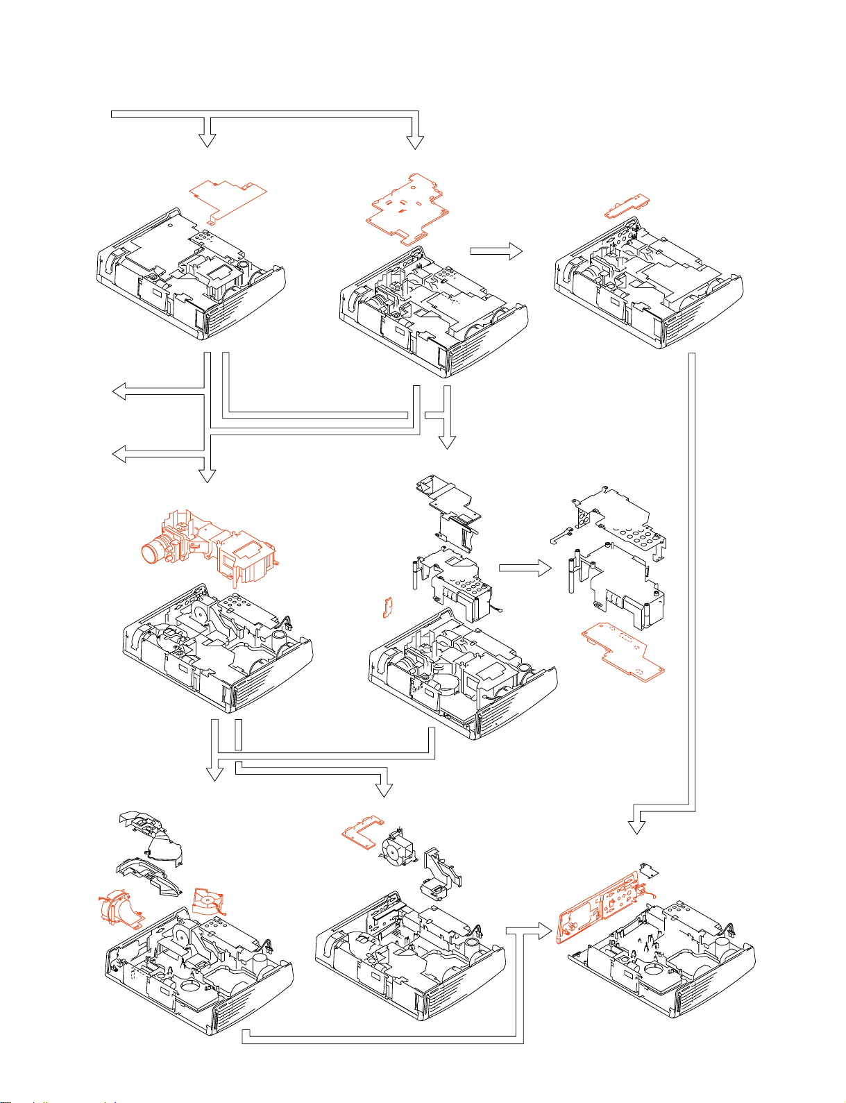
A
1-3-4. Plate (LH)
B
C
1-3-9. Optics Block Assembly
1-3-7. C Board
1-3-8. QA Board
1-3-10. V Board
1-3-11. GB Board
1-3-12. D.C. Fan (Sirocco) (72 x 75)
VPL-CX85
1-3-14. QB Board
1-3-15. H2 Board and Door (Side)
1-3
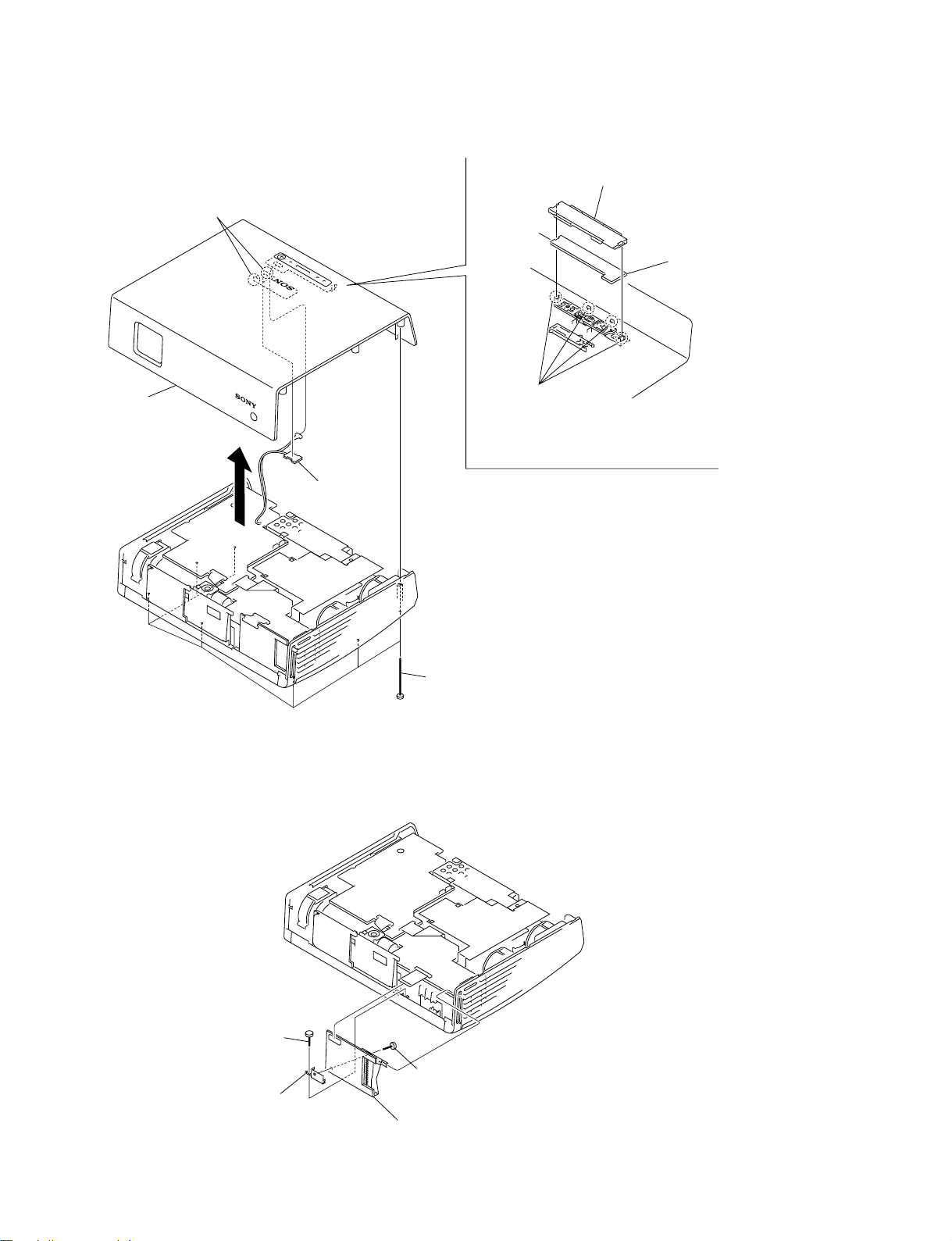
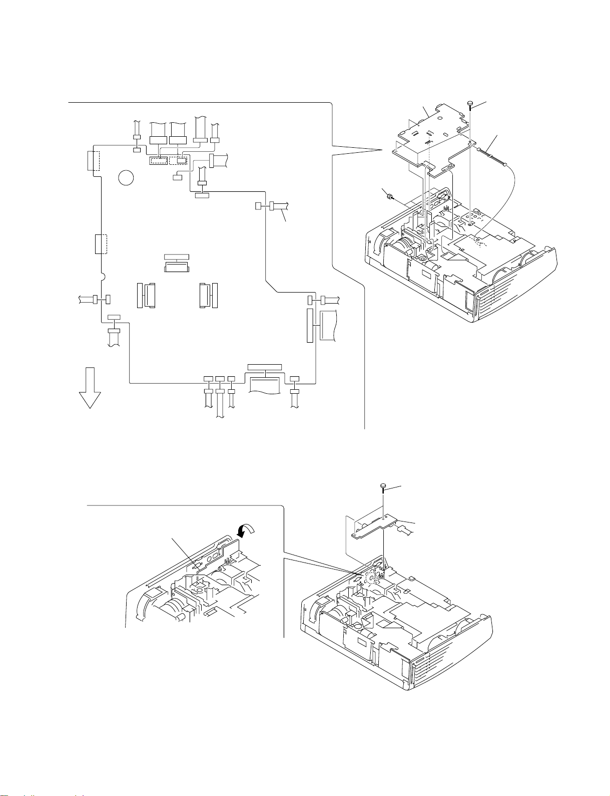
1-3-1. Top Cover
2 Two claws
6 Bracket (H1)
7 H1 board
4 Top cover
1-3-2. QC Board
5 Four claws
CN50
3 L board
1 Seven screws
(+PSW M3 x 70)
1-4
1 Screw
(+PSW M3 x 6)
3 Holder (QC)
CN2101
2 Screw
(+PSW M3 x 6)
4 QC board, Frame (CF)
VPL-CX85
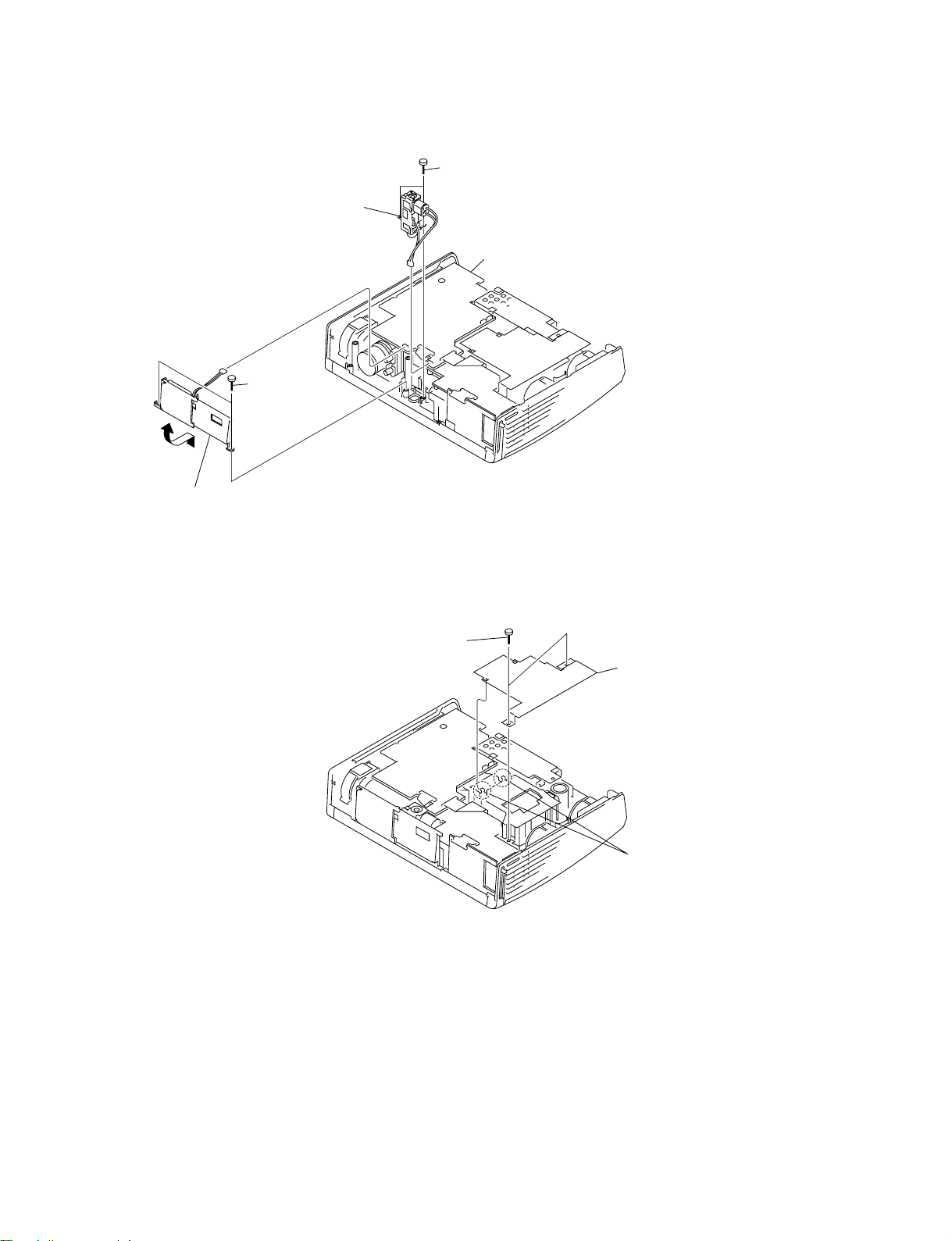
1-3-3. Adjustor Unit
3 Two screws
(+PSW M3 x 6)
4 Adjustor unit
CN506
2 Remove the shutter unit
in the direction of the arrow.
1-3-4. Plate (LH)
1 Two screws
(+PSW M3 x 6)
CN505
1 Two screws
(+PSW M3 x 6)
C board
3 Plate (LH)
VPL-CX85
2 Two claws
1-5
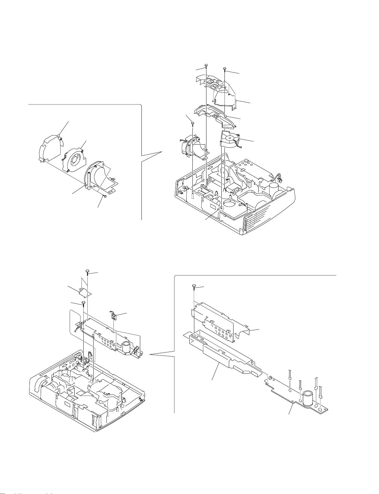
1-3-5. NR Board and Lamp Power Supply
4 Lamp power supply,
Shield (BAL) and
2 Two screws
(+PSW M3 x 6)
CN206
CN204
Sheet (BAL)
CN103
3 Three claws
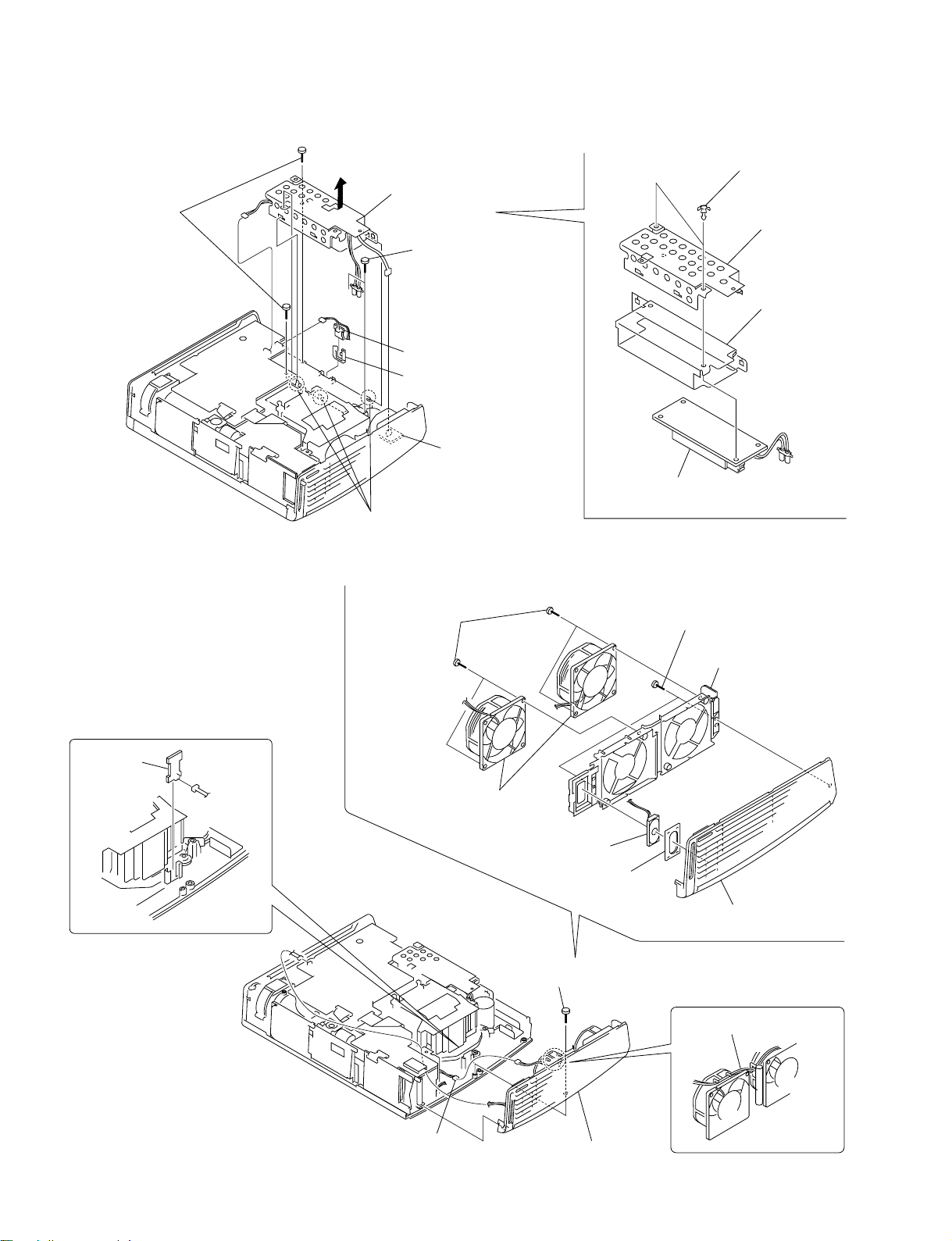
1-3-6. U Board and Speaker Assembly
7 Two PC board supports
8 Shield (BAL)
1 Two screws
(+PTPWH 3 x 10)
9 Sheet (BAL)
6 NR board
5 Holder (NR)
GA board
0 Lamp power supply
5 U board
CN20
CN402
!-
Four screws
(+PSW M3 x 6)
!=
Two D.C. fans
0
Speaker assembly
9
Sheet (SP)
1 Screw
(+PSW M3 x 6)
6
T wo screws
(+PSW M3 x 6)
7
Fan holder (EX)
8
Side (R) panel
2 Remove the harnesses.
1-6
3 Connector
4 Side (R)
panel section
VPL-CX85
1-3-7. C Board
CN202
CN601CN301
CN206
CN600
CN204
4 C board
1 Four hexagon
screws
2 Three screws
(+PSW M3 x 6)
3 Fuse connector
assembly
CN205
CN1700
CN402
CN211
Front Side
of Unit
1-3-8. QA Board
CN1600
CN210
C board
CN502
CN1800
CN203
CN205
CN506
Fuse connector
assembly
CN200
CN201
CN500
CN505
1 Two screws
(+PSW M3 x 6)
2 Remove the QA board
in the direction of the arrow.
VPL-CX85
3 QA board
CN11
1-7

1-3-9. Optics Block Assembly
2 Six screws
(+PSW M3 x 10)
4 Remove the optics block assembly
in the direction of the arrow B.
3 Push this portion by arrow A.
Position of the Polarization panel assembly (Pre),
Polarization panel assembly
1 Two screws
(+PTPWH 3 x 10)
B
Lamp power supply
A
Polarization panel (G) assembly (Pre)
Polarization panel (G) assembly
Green
(Top view)
Red
Polarization panel (R) assembly
Polarization panel (R) assembly (Pre)
Polarization panel
(B) assembly
Polarization panel
(B) assembly (Pre)
Blue
!] Polarization panel
(R) assembly

1-3-10.V Board
1 Four screws
(+PSW M3 x 6)
2 QC board,
M board
3 Two screws
(+PSW M3 x 6)
5 GB section
6 V board
1-3-11.GB Board
5 Bracket
CN30
4 Connector
1 Two screws
(+PSW M3 x 6)
2 Shield (GBA)
VPL-CX85
4 Two screws
(+PSW M3 x 6)
CN402
CN403
CN401
CN203
CN201
7 Holder
(GB)
CN202
8 GB board
3 Two screws
(+PSW M3 x 6)
6 Flat connector
assembly (24P)
1-9
1-3-12.D.C Fan (Sirocco) (72
xx
x 75)
xx
2 Screw
(+PSW M3 x 10)
1 Four screws
(+PSW M3 x 10)
9 Fan holder (PB)
0 Fan holder (PA)
1-3-13.GA Board
2 Shield (Inlet)
4 Four screws
(+PSW M3 x 6)
!- D.C. fan (Sirocco)
(72 x 75)
8 Two screws
(+PSW M3 x 10)
1 Two screws
(+PSW M3 x 6)
7 Two screws
(+PSW M3 x 10)
3 NR board
Holder (NR)
3 Prism duct (Cover)
6 Prism duct (Base)
5 D.C. fan (Sirocco)
(72 x 75)
4 Claw
5 Three screws
(+PSW M3 x 6)
6 Shield (GA)
1-10
CN101
7 Sheet (GA)
CN102
CN104
8 GA board
CN103
CN105
VPL-CX85
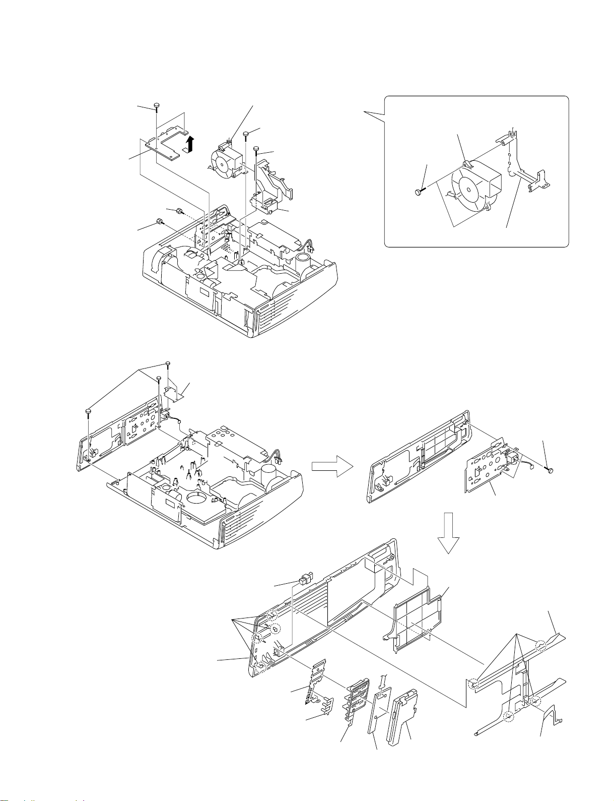
1-3-14.QB Board
7 Two screws
(+PSW M3 x 6)
8 QB board
4 D.C. fan (Sirocco) (60 x 80),
Lamp fan holder (A)
2 Screw (+PSW M3 x 6)
1 Two screws
(+PSW M3 x 6)
!- D.C. fan (Sirocco)
(60 x 80)
9 Two screws
(+PSW M3 x 10)
6 Two hexagon
screws
5 Two hexagon
screws
1-3-15.H2 Board and Door (Side)
1 Four screws
(+PSW M3 x 6)
2 Shield (Inlet)
CN101
3 Ballast (Cover) duct,
Ballast (Base) duct
0 Lamp fan holder (A)
3 Two screws
(+PSW M3 x 6)
VPL-CX85
0 Four claws
!; Side (L) panel
9 Push catcher
!= Shield (H2)
![ Light guide (H2)
!] Key (H2)
CN70
!- Holder (H2)
!\ H2 board
4 Terminal A,
AC inlet assembly
8 Door (Side)
7 Terminal
board B
6 Four claws
5 Spring plate
(Side)
1-11

1-3-16.Extension Boards and Extension Connectors
X kit assembly (Part No. A-1066-122-A)
XC board x1 XF32 board x 3 Harness x 14 Flat cable x5
1-3-17.Extension Boards and Extension Connectors Connection
1. C board extension with using XC and XF32 extension boards.
C board
Three XF32 boards
XC board
To C board
CN202 (4P)
From GA board
CN102 (4P)
From QA board CN11 (11P)
From QB board
CN53 (12P)
To C board
CN600 (12P)
To C board
CN301 (11P)
From QB board
CN51 (7P)
To C board
CN601 (7P)
CN5202
CN600
CN5600
CN202
CN5601
CN601
CN5301
CN5204
From U board CN20 (3P),
NR board CN10 (3P)
CN204CN301
CN206
CN5206
From Lamp power supply (5P)
To C board CN206 (5P)
To C board CN204 (6P)
1-12
To C board
CN402 (2P)
From speaker
(2P)
From H2 board
CN70 (8P)
To C board
CN211 (8P)
XC board
CN402
CN211
CN5402
CN5211
To C board
CN502 (4P)
From lens (4P)
FRONT SIDE
OF UNIT
CN5203
CN5502
CN502 CN203
CN5506
CN506
CN5200 CN200
CN201
CN5505
CN5201
CN5209
CN209CN505
To C board CN506 (6P)
From shutter (5P)
From V board CN30 (7P)
To C board CN203 (7P)
To C board
CN200 (6P)
From GB board
CN401 (6P)
From GB board
CN203 (24P)
To C board
CN201 (24P)
From Tilt ADJ (5P)
To C board
CN505 (5P)
VPL-CX85

From XC board CN5506 (6P)
From XC board CN5505 (5P)
From XC board
CN5211 (8P)
From XC board CN5206 (5P)
From XC board CN5204 (6P)
From XC board CN5601 (7P)
From XC board CN5600 (12P)
From XC board CN5301 (11P)
From H1 board CN50 (8P),
L board CN90 (2P)
From XC board
CN5402 (2P)
From XC board
CN5200 (6P)
From XC board
CN5201 (24P)
From XC board CN5203 (7P)
From M board CN1003 (68P)
From XC board CN5502 (4P)
From TH fuse assembly (2P)
From prism assembly
LCD (Blue) (32P)
From prism assembly
LCD (Red) (32P)
From prism assembly
LCD (Green) (32P)
From XC board CN5202 (4P)
XF32 board
XF32 board
XF32 board
FRONT SIDE
OF UNIT
CN202
CN206
CN210
CN600
CN601
CN301
CN204
CN402
CN505
CN506
CN502
CN211
CN205
CN200
CN201
CN203
CN500
C board
CN1600
CN1800
CN1700
VPL-CX85
1-13
1-4. Writing in the USB Storage Media
When replacing the USB storage media, copy the following files into the USB storage media 8-892-388-
39.
. \AS_Inst.exe
. \Help\PS for Air Shot\ENG\PSAirShot.chm
. \Help\PS for Air Shot\JPN\PSAirShot.chm
. \INI\as_inst.ini
. \ReadMe\PS for Air Shot\ENG\ReadMe.txt
. \ReadMe\PS for Air Shot\JPN\ReadMe.txt
. \Setup\PS for Air Shot\0x0409.ini
. \Setup\PS for Air Shot\0x0411.ini
. \Setup\PS for Air Shot\Data1.cab
. \Setup\PS for Air Shot\instmsia.exe
. \Setup\PS for Air Shot\instmsiw.exe
. \Setup\PS for Air Shot\isscript.msi
. \Setup\PS for Air Shot\Projector Station for Air Shot.msi
. \Setup\PS for Air Shot\setup.exe
. \Setup\PS for Air Shot\Setup.ini
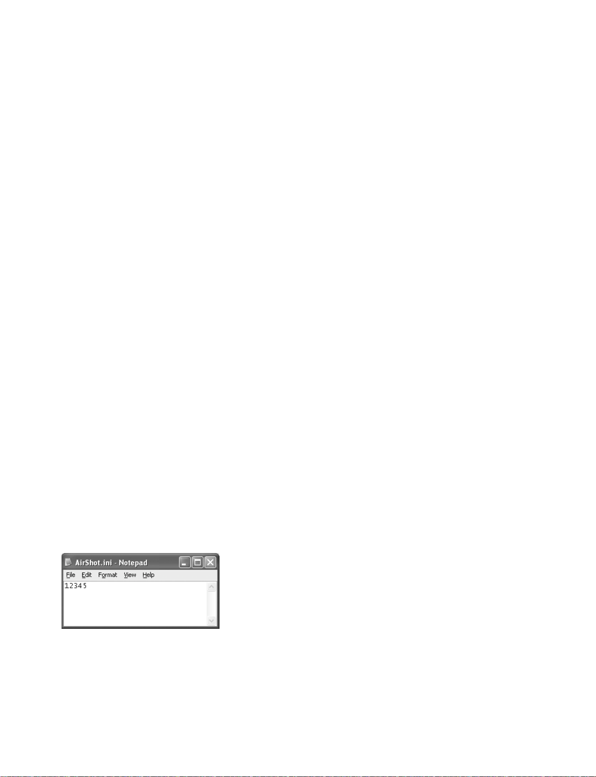
. \Setup\PS for Air Shot\AirShot.ini (*Note)
m
. Be sure to copy the files of the newest version into the USB storage media.
. The AirShot.ini is different depending on the serial number of the projector. (Refer to Note : Method
to create the AirShot.ini file.)
Method to create the AirShot.ini file
1. Check the serial number of the target projector.
2. Open a text editor application of a PC, and type the lower five digits of the serial number. If the
serial number is six digits or more, type only the lower five digits of the serial number. If the serial
number is less than five digits, fill the blank digits with 0.
Example : When serial number is 1 → 00001
When serial number is 1234567 → 34567
3. Save the created text file as “AirShot.ini”.
1-14
VPL-CX85

1-5. Warning on Power Connection
Use the supplied power cord when you use the projector in your country.
Otherwise, use a proper power cord meeting the following specification.
The United States, Continental Europe UK, Ireland, Japan
Canada
Plug type VM0233 290B YP-12A COX-07 –
Female end VM0089 386A YC-13B COX-02 VM0310B YC-13
Cord type SJT SJT H05VV-F H05VV-F N13237/CO-228 VCTF
Rated Voltage & Current 10A/125V 10A/125V 10A/250V 10A/250V 10A/250V 7A/125V
Safety approval UL/CSA UL/CSA VDE VDE VDE DENAN
Cord length (max.) 4.5 m (177 1/4 inches) –
(1) Use the correct plug for your country.
Australia,
New Zealand
1)
YP332
VPL-CX85
1-15


Section 2
Electrical Adjustments
2-1. Preparation
2-1-1. Required Equipment
. NTSC, PAL, SECAM component signal generator
Sony Tektronix TG2000 + AVG1 (option module) +
AWVG1 (option module) or equivalent
. VG (programmable video signal generator)
VG854 or equivalent
. Illuminance meter
. Chromaticity meter
n
Allow the warm-up time of 5 minutes after the power is on
before starting the following adjustments.
2-1-2. How to Enter the Factory Mode
1. Confirm that the MENU can be displayed.
2. Close the MENU.
3. Press the keys in the following order : [ENTER] →
[ENTER] → [&] → [ENTER].
The message [Do you want to enter the Factory Mode?
Yes : ↑ No : ↓] appears.
Select [Yes : ↑].
[Supplementary information: How to Exit the
Factory Mode]
Perform the step 3 KEY operation.
The message [Do you want to return to the User Mode?
Yes : ↑ No : ↓] appears.
Select [Yes : ↑].
2-2. V COM Adjustment
1. Connect the VG to the INPUT-A connector. Connect
the FLAT FIELD 100 IRE signal to the input connector. Leave this unit with POWER ON for 10 minutes
or longer for aging.
2. Enter the Factory Mode. Enter the Device Adjust
MENU, and then enter the Panel Drive Adjustment
MENU.
3. Connect the XGA, R-single color, 30 IRE, single-line
ON/OFF signal to the input connector.
4. Enter the P. DRV Adjustment MENU, and then enter
the VCOM R Adjustment screen.
5. Adjust the VCOM R value for minimum flicker.
6. Change the input signal to the XGA, G-single color,
30 IRE, single-line ON/OFF signal, and connect it to
the input connector.
7. Enter the P. DRV Adjustment MENU, and then enter
the VCOM G Adjustment screen.
8. Adjust the VCOM G value for minimum flicker.
9. Change the input signal to the XGA, B-single color, 50
IRE, single-line ON/OFF signal, and connect it to the
input connector.
10. Enter the P. DRV Adjustment MENU, and then enter
the VCOM B Adjustment screen.
11. Adjust the VCOM B value for minimum flicker.
12. Store the adjustment value in the memory.
13. Turn over the “Image flip” up side down and repeat
the steps from 2 through 12.
VPL-CX85
2-1

2-2
MemoryName
Picture Memory W/B Memory
Video S Video Input-A Input-B Input-C Video Computer
Dynamic Standard Dynamic Standard Dynamic Standard Dynamic Standard Dynamic Standard High Low High Low
PICTURE
SETTING
Picture Mode Standard
Adjust Picture...
Contrast 95 80 95 80 95 80 95 80 95 80
Brightness 50 50 50 50 50 50 50 50 50 50
Color 50 50 50 50 50 50
Hue 50 50 50 50 50 50
Sharpness High High High High High High
Gamma Mode ----Graphics Graphics Graphics Graphics Graphics Graphics
Color Temp. Low Low Low Low High High High High High High
Volume 30
Adjust Signal...
Dot Phase
15 (*)
H Size
*
Shift
*
Wide Mode Off Off Off Off Off Off
Scan Conv On On On On
Smart APA On
Auto Input Search Off
Input-A Signal Sel. Computer
Input-C Select Air Shot
Color System Auto
Speaker On
Standby Mode Standard
Power Saving Off
IR Receiver Front & Rear
Illumination On
Panel Key Lock Off
Status On
Languege English
Menu Position Center
Menu Color White
MENU
SETTING
Remarks
Set Memory
Status
Memory
INPUT
SETTING
SET
SETTING
MenuTitle ItemName
2-3. Initial Values of Adjustment Items
VPL-CX85
VPL-CX85
MemoryName
Picture Memory W/B Memory
Video S Video Input-A Input-B Input-C Video Computer
Dynamic Standard Dynamic Standard Dynamic Standard Dynamic Standard Dynamic Standard High Low High Low
Tilt...
V Keystone Auto
Manual... 0
Side Shot 0
Image Flip Off
Background Blue
Test Pattern Off
Lamp Mode Standard
Lens Control On
Direct Power On Off
High Altitude Off
Security Lock Off
Default Enter x 4
fH Display only
fV Display only
(Memory No.) Display only
(Resolution) Display only
Lamp Timer Display only
ROM Version Display only
SC ROM Version Display only
Operation Timer Display only
Prev. Lamp Timer Display only
Gain R 152 152 152 152
G 152 140 152 140
B 152 140 152 140
Bias R 127 127 127 127
G 127 127 127 127
B 127 127 127 127
INSTALL
SETTING
Remarks
INFORMA
-TION
W/B
SETTING
MenuTitle ItemName
Set Memory
Status
Memory
* : The “Dot Phase E, H Size, Shift H/V and Picture Mode” items in the “INPUT SETTING” menu have their respective initial values for each input signal (PRESET
MEMORY No.).
n
There are some adjustment items that cannot be adjusted, depending on the input signal.
2-3

2-4
MemoryName
Chroma Memory Channel Memory
NT358/
NT443/
BW60
Pal/Pal-M/N/
Secam/
BW50
15
kRGB
Component
(15k)
Double
speed
Component
HDTV
(YPbPr)
HDTV(G
BR)inc.
Double
speed
Video
S
Video
Input
-A
Input
-B
Input
-C
Up/Down
inversion
possible
Up/Down
inversion
not
possible
ADC/
Clamp Position
*1
Clamp Width
*1
R Gain(Other)
15 - 888888
R Gain(Component)
--80--
R Gain(VideoGBR)
--88--
G Gain(Other)
- 15888888
G Gain(Component)
- - 120 - -
G Gain(VideoGBR)
--88--
B Gain(Other)
- 15888888
B Gain(Component)
--80--
B Gain(VideoGBR)
--88--
R Offset(Other)
126 - 128 128 128
R Offset(Component)
- - 128 - -
R Offset(VideoGBR)
- - 128 - -
G Offset(Other)
- 128 128 128 128
G Offset(Component)
- - 128 - -
G Offset(VideoGBR)
- - 128 - -
B Offset(Other)
- 128 128 128 128
B Offset(Component)
- - 128 - -
B Offset(VideoGBR)
- - 128 - -
Bandwidth
3
Chroma/ Dither 2 2222
Vd 10BitEn 1 1111
Secam Nbw 1 1111
Line2 A Sync 15 15 15 15 15
Line2 H Sync 7 7777
Line2 Los 31 31 31 31 31
End Clamp 64
Status 1 Display only
Status 2 Display only
P.Drv Offset R 122 122
Offset G 122 122
Offset B 122 122
V Common R 92 92
V Common G 92 92
V Common B 92 92
Psig 1 R 12
Psig 1 G 12
Psig 1 B 12
Psig 2 R 83
Psig 2 G 83
Psig 2 B 83
Signal Center R 30
Signal Center G 30
Signal Center B 30
Gain R 160
Gain G 160
Gain B 160
SH/ SH1 32
Status
Memory
Set Memory
A/D
Converter
Device
Name
Item Name
Image Flip Memory
Chroma/
D.Comb
Panel
Driver
Remarks
VPL-CX85

VPL-CX85
MemoryName
Chroma Memory Channel Memory
NT358/
NT443/
BW60
Pal/Pal-M/N/
Secam/
BW50
15
kRGB
Component
(15k)
Double
speed
Component
HDTV
(YPbPr)
HDTV(G
BR)inc.
Double
speed
Video
S
Video
Input
-A
Input
-B
Input
-C
Up/Down
inversion
possible
Up/Down
inversion
not
possible
Other 3D Through 0
SW 1
HST Width 0
Temp/ Thresh Lamp
Non Adjustable Non Adjustable
Thresh Panel
Non Adjustable Non Adjustable
Thresh Atmos
Non Adjustable Non Adjustable
Fan/ Hi Alt Const
Non Adjustable Non Adjustable
High Alt Cofe
Non Adjustable Non Adjustable
Fan1/ Cont Max
Non Adjustable Non Adjustable
Speed Max
Non Adjustable Non Adjustable
Speed Min
Non Adjustable Non Adjustable
Cont Slope
Non Adjustable Non Adjustable
Fan2/ Cont Max
Non Adjustable Non Adjustable
Speed Max
Non Adjustable Non Adjustable
Speed Min
Non Adjustable Non Adjustable
Cont Slope
Non Adjustable Non Adjustable
Fan3/ Cont Max
Non Adjustable Non Adjustable
Speed Max
Non Adjustable Non Adjustable
Speed Min
Non Adjustable Non Adjustable
Cont Slope
Non Adjustable Non Adjustable
Other/ Synchronous 1
Tilt C0
Factory adj. Value
Tilt C1
Factory adj. Value
Tilt C2
Factory adj. Value
X Tilt Display only
Y Tilt Display only
TL Display only
TP Display only
TA Display only
Gamma
Factory adj. Value
Device
Name
Item Name
Set Memory
Status
Memory
Image Flip Memory
Remarks
n
There are some adjustment items that cannot be adjusted, depending on the input signal.
2-5

2-4. Service Know-How
2-4-1. When the Prism Block Is Replaced
1. Perform the V COM adjustment. (Refer to Section “2-
2. VCOM Adjustment”.)
2. Write LUT and 3D GAMMA data that are supplied
with the prism block.
3. Perform the white balance adjustment. (Refer to
Section “2-5. White Balance Adjustment”.)
2-4-2. When the Board is Replaced
n
No item needs to be adjusted when boards other than the C
board are replaced.
When the C board is replaced
1. Install the IC103 and IC1503 that are removed from
the old C board, into the new C board.
2. Enter the Factory Mode, and select Other in DEVICE
ADJUST.
3. Shorten the TILT adjuster to its shortest limit on the
flat workbench.
4. At this time, the value of 38 Other/X Tilt is read and
inputted in the 35 Other/Tilt C0.
5. Secure the unit so that it faces upward in the vertical
position.
6. At this time, the value of 38 Other/X Tilt is read and
inputted in the 36 Other/Tilt C1.
7. Secure the unit so that it faces downward in the
vertical position.
8. At this time, the value of 38 Other/X Tilt is read and
inputted in the 37 Other/Tilt C2.
9. Press the MEMORY key and save the adjustment
value.
n
Perform adjustment under the environment of 25 ±5dC.
2-6
VPL-CX85
 Loading...