

Sony RDR-HX680,RDR-HX780,RDR-HX785,RMT-D246A,RMT-D249P,RMT-D250P,RDR-HX1080,RDR-HX980 Service Manual
System
Laser: Semiconductor laser
Channel coverage:
PAL (
AEP, UK, Russian model
B/G, D/K, I)/SECAM (L)
VHF: E2 to E12, R1 to R12, F2 to
F10, Italian A to H, Ireland A to J,
South Africa 4 to 11, 13
UHF: E21 to E69, R21 to R69, B21 to
B69, F21 to F69
CATV: S01 to S05, S1 to S20, France
B to Q
HYPER: S21 to S41
The above channel coverage merely ensures
the channe l rece ptio n with in thes e rang es. It
does not guarantee the ability to receive
signals in all circumstance s. The channels
that can be received differ depending on the
country/region.
Video reception: Frequency
synthesizer system
Audio reception: Split carrier system
Aerial out: AEP, UK, Russian model
Antenna out: Canadian, E model
Channel coverage:
Canadian, E model
NTSC
VHF: 2 to 13
UHF: 14 to 69
CATV: A8 to A1, A to W, W+1 to W+84
75-ohm asymmetrical aerial
socket
Timer: Clock: Quartz locked/Timer
indication: 24-hour cycle (digital)
Video recording format: MPEG-2,
MPEG-1
Audio recording format/applicable
bit rate: Dolby Digital 2 ch
256 kbps/128 kbps (in EP, SLP, and
SEP mode), PCM
Inputs and outputs
LINE 2
LINE OUT: Canadian, E model
OUT: AEP, UK, Russian model
(AUDIO): Phono jack/2 Vrms/10 kilohms
(VIDEO): Phono jack/1.0 Vp-p
(S VIDEO): 4-pin mini DIN/Y: 1.0 Vp-p,
C
C: 0.286 Vp-p (NTSC)
C: 0.286 Vp-p (NTSC)
: 0.3 Vp-p (PAL)
LINE 2
LINE IN 1/2/3: Canadian, E model
IN: AEP, UK, Russian model
(AUDIO): Phono jack/2 Vrms/more than
22 kilohms
(VIDEO): Phono jack/1.0 Vp-p
(S VIDEO): 4-pin mini DIN/Y: 1.0 Vp-p,
C: 0.3 Vp-p (PAL)
LINE 3 – TV: 21-pin
CVBS OUT
S-Video/RGB OUT (upstream)
LINE 1/DECODER: 21-pin
CVBS IN/OUT
S-Video/RGB IN
Decoder
DV IN: 4-pin/i.LINK S100
DIGITAL OUT (COAXIAL): Phono
jack/0.5 Vp-p/75 ohms
COMPONENT VIDEO OUT
(Y, P
B/CB, PR/CR):
(Y, P
B, PR):
AEP, UK, Russian model
AEP, UK, Russian model
AEP, UK, Russian model
Canadian, E model
Phono jack/Y: 1.0 Vp -p,
P
B/CB: 0.7 Vp-p, PR/CR: 0.7 Vp-p
G-LINK*: mini jack
HDMI OUT: HDMI™ Connector
USB:
USB jack Type A (For connecting
digital still camera, Memory card
reader, USB memory and HDD
camcorder)
USB jack Type B (For connecting
PictBridge-compat ibl e prin te rs )
General
Power requirements: 220-240 V AC,
50/60 Hz
Power consumption:
43 W AEP, UK, Russian model
42 W Canadian, E model
Dimensions (approx.):
430 ⋅ 66.5 ⋅ 286.5 mm (width/height/
depth) incl. projecting parts
Hard disk drive capacity:
RDR-HX680/HX780/HX785:
160 GB
RDR-HX980: 250 GB
RDR-HX1080: 500 GB
Mass (approx.): 4.4 kg
Operating temperature: 5ºC to 35ºC
Operating humidity: 25% to 80%
Supplied accessories:
Mains lead (1)
Aerial cable (1)
Re
Audio/video card (1) Canadian, E model
mote commander (remote) (1)
Set top box controller (1)*
R6 (size AA) batteries (2)
*RDR-HX780/HX785/HX980/HX1080
Specifications and design are subject to
change without notice.
AEP model only
Q
Q
3
7
6
3
1
RDR-HX680/HX780/HX785/
5
1
5
0
8
HX980/HX1080
RMT-D246A/D249P/D250P
9
2
4
9
8
2
9
9
SERVICE MANUAL
Ver. 1.0 2008.04
TEL 13942296513 QQ 376315150 892498299
(AEP)
TEL
w
13942296513
w
w
9-883-980-11
.
xia
o
y
Photo: RDR-HX780
RMT-D246A
SPECIFICATIONS
Q
Q
u
1
6
Sony Corporation
Home Electronics Network Company
RDR-HX680/HX780/HX785/HX980/
Australian Model
Singapore Model
(AEP, UK, Russian)
1
3
6
7
3
3
.
1
5
c
5
o
8
0
m
Published by Quality Assurance Dept.
AEP Model
HX1080
Canadian Model
UK Model
E Model
RDR-HX780
Russian Model
TEL 13942296513 QQ 376315150 892498299
Thai Model
RDR-HX780/HX980
9
9
2
8
9
4
2
9
DVD RECORDER
2008D1600-1
©2008.04
WARNING!!
7
Q
Q
WHEN SERVICING, DO NOT APPROACH THE LASER EXIT WITH
THE EYE TOO CLOSELY. IN CASE IT IS NECESSARY TO
CONFIRM LASER BEAM EMISSION, BE SURE TO OBSERVE
FROM A DIST ANCE OF MORE THAN 25 cm FROM THE SURF ACE
OF THE OBJECTIVE LENS ON THE OPTICAL PICK-UP BLOCK.
CAUTION:
The use of optical instrument with this product will increase eye
hazard.
CAUTION
Use of controls or adjustments or performance of procedures
other than those specified herein may result in hazardous radiation
exposure.
TEL 13942296513 QQ 376315150 892498299
COMPONENTS IDENTIFIED BY MARK 0 OR DOTTED LINE WITH
MARK 0 ON THE SCHEMATIC DIAGRAMS AND IN THE PARTS
LIST ARE CRITICAL TO SAFE OPERATION. REPLACE THESE
COMPONENTS WITH SONY PARTS WHOSE PART NUMBERS
APPEAR AS SHOWN IN THIS MANUAL OR IN SUPPLEMENTS
PUBLISHED BY SONY.
3
SAFETY-RELATED COMPONENT WARNING!!
6
3
1
5
1
5
Unleaded solder
Boards requiring use of unleaded solder are printed with the lead-
0
free mark (LF) indicating the solder contains no lead.
(Caution: Some printed circuit boards may not come printed with
the lead free mark due to their particular size.)
: LEAD FREE MARK
Unleaded solder has the following characteristics.
• Unleaded solder melts at a temperature about 40°C higher than
ordinary solder.
Ordinary soldering irons can be used but the iron tip has to be
applied to the solder joint for a slightly longer time.
Soldering irons using a temperature regulator should be set to
about 350°C.
Caution: The printed pattern (copper foil) may peel away if the
heated tip is applied for too long, so be careful!
• Strong viscosity
Unleaded solder is more viscous (sticky, less prone to flow) than
ordinary solder so use caution not to let solder bridges occur such
as on IC pins, etc.
• Usable with ordinary solder
It is best to use only unleaded solder but unleaded solder may
also be added to ordinary solder.
Special Component Notice
The components identified by mark 9 contain confidential
information.
Strictly follow the instructions whenever the components are repaired
and/or replaced.
8
9
2
4
9
8
2
9
9
TEL 13942296513 QQ 376315150 892498299
TEL
1. Check the area of your repair for unsoldered or poorly-soldered
connections. Check the entire board surface for solder splashes
and bridges.
2. Check the interboard wiring to ensure that no wires are
"pinched" or contact high-wattage resistors.
3. Look for unauthorized replacement parts, particularly
transistors, that were installed during a previous repair. Point
them out to the customer and recommend their replacement.
13942296513
After correcting the original service problem, perform the following
safety checks before releasing the set to the customer.
SAFETY CHECK-OUT
8
9
4
2
9
8
0
5
1
5
1
3
6
7
3
Q
Q
4. Look for parts which, through functioning, show obvious signs
of deterioration. Point them out to the customer and
recommend their replacement.
5. Check the B+ voltage to see it is at the values specified.
6. Flexible Circuit Board Repairing
• Keep the temperature of the soldering iron around 270˚C
during repairing.
• Do not touch the soldering iron on the same conductor of the
circuit board (within 3 times).
• Be careful not to apply force on the conductor when soldering
or unsoldering.
2
9
9
w
w
w
.
xia
o
y
u
1
6
3
— 2 —
.
c
o
m

TABLE OF CONTENTS
1. SERVICE NOTE
Q
TEL 13942296513 QQ 376315150 892498299
1. DISK REMOVAL PROCEDURE IF THE TRAY
Q
2. BOARD CONNECTION, SER VICE REMOTE
3. MODEL NAME SETTING METHOD WHEN ENGINE
4. HOW TO DIAGNOSE HDD FAILURE························· 1-3
4-1. Defective HDD ································································1-3
4-2. HDD Recognition status··················································1-3
4-3. Display [E01] on FLD with unrecognized HDD·············1-4
4-4. Display [E02] on FLD ·····················································1-5
4-5. When playing a video, MP3, or JPG, the contents freeze1-5
4-6. Factory Check··································································1-6
4-7. Final Check······································································1-6
2. DISASSEMBLY
2-1. UPPER CASE ·································································2-2
2-2. TRAY COVER ASSEMBLY ··········································2-2
2-3. FRONT PANEL BLOCK················································2-3
2-4 FR-291 BOARD, FL-184 BOARD ·································2-3
2-5. DVD UNIT ······································································2-4
2-6. DC FAN···········································································2-5
2-7. HARD UNIT ··································································· 2-5
2-8. A V-133/134 BOARD ·······················································2-6
2-9. SWITCHING REGULATOR·········································· 2-6
2-10. CIRCUIT BOARDS LOCATION···································2-7
3. BLOCK DIAGRAMS
3-1. OVERALL BLOCK DIAGRAM-1 ································3-1
3-2. OVERALL BLOCK DIAGRAM-2 ································3-3
3-3. AV-133 BLOCK DIAGRAM ··········································3-5
TEL
3-4. AV-134 BLOCK DIAGRAM ··········································3-7
3-5. RD-066 BLOCK DIAGRAM ········································· 3-9
3-6. FR-291, FL-184, VDC-001 BLOCK DIAGRAM ········ 3-11
3-7. POWER BLOCK DIAGRAM ······································3-13
4. SCHEMATIC DIAGRAMS AND
4-1. FRAME SCHEMATIC DIAGRAM································4-1
4-2. SCHEMA TIC DIAGRAMS ············································4-3
7
3
CANNOT BE EJECTED (FORCED EJECTION) ·········1-1
CONTROLLER······························································· 1-1
IS REPLACED ································································1-2
6
13942296513
PRINTED WIRING BOARDS
WAVEFORMS ································································4-3
• AV-133 (1/5) (IT CONTROLLER, IR)
SCHEMATIC DIAGRAM······························4-5
• AV-133 (2/5) (POWER/FAN CONT.)
SCHEMATIC DIAGRAM······························4-7
• AV-133 (3/5) (VIDEO/AUDIO)
SCHEMA TIC DIAGRAM······························4-9
• AV-133 (4/5) (EURO)
SCHEMA TIC DIAGRAM····························4-11
• AV-133 (5/5) (TUNER)
SCHEMATIC DIAGRAM····························4-13
• AV-134 (1/5) (IT CONTROLLER, IR)
SCHEMATIC DIAGRAM····························4-15
• AV-134 (2/5) (POWER/FAN CONT.)
SCHEMATIC DIAGRAM····························4-17
3
1
5
1
5
0
Q
Q
7
3
4-3. PRINTED WIRING BOARDS ·····································4-49
5. IC PIN FUNCTION DESCRIPTION
5-1. IT CONTROL IC
5-2. AV ENCODER/DECODER IC
• AV-134 (3/5) (VIDEO/AUDIO)
SCHEMATIC DIAGRAM···························· 4-19
9
8
• AV-134 (4/5) (JACK)
SCHEMATIC DIAGRAM···························· 4-21
• AV-134 (5/5) (TUNER)
SCHEMATIC DIAGRAM···························· 4-23
• FR-291 (FL DRIVER, LINE 2 IN, FUNCTION SW)
SCHEMATIC DIAGRAM···························· 4-25
• FL-184 (DV, USB, REMOCON RECEIVER, ··················
POWER SW)
SCHEMATIC DIAGRAM···························· 4-27
• RD-066 (1/7) (POWER BLOCK)
SCHEMATIC DIAGRAM···························· 4-29
• RD-066 (2/7) (EMMA BLOCK)
SCHEMATIC DIAGRAM···························· 4-31
• RD-066 (3/7) (VIDEO/AUDIO BLOCK)
SCHEMATIC DIAGRAM···························· 4-33
• RD-066 (4/7) (MEMORY BLOCK)
SCHEMATIC DIAGRAM···························· 4-35
• RD-066 (5/7) (SATA/IDE IF)
SCHEMATIC DIAGRAM···························· 4-37
• RD-066 (6/7) (HDMI/DV/USB BLOCK)
SCHEMATIC DIAGRAM···························· 4-39
• RD-066 (7/7) (DVD DRIVE)
SCHEMATIC DIAGRAM···························· 4-41
• SWITCHING REGULATOR (SRV-2101EK)
SCHEMATIC DIAGRAM···························· 4-43
• SWITCHING REGULATOR (SRV-2058EK)
SCHEMATIC DIAGRAM···························· 4-45
• SWITCHING REGULATOR (SRV-2059WW)
SCHEMATIC DIAGRAM···························· 4-47
5
1
3
6
• FR-291 (FL DRIVER, LINE 2 IN, FUNCTION SW)
PRINTED WIRING BOARD ·······················4-49
• AV-133 (IT CONTROLLER, IR, POWER/FAN CONT.,
VIDEO/AUDIO, EURO, TUNER)
PRINTED WIRING BOARD ·······················4-51
• AV-134 (IT CONTROLLER, IR, POWER/FAN CONT.,
VIDEO/AUDIO, EURO, TUNER)
PRINTED WIRING BOARD ·······················4-55
• RD-066 (POWER BLOCK, EMMA BLOCK, VIDEO/
AUDIO BLOCK, MEMORY BLOCK, SATA/IDE IF,
HDMI/DV/USB BLOCK, DVD DRIVE)
PRINTED WIRING BOARD ·······················4-59
• FL-184 (DV, USB, REMOCON RECEIVER,
POWER SW)
PRINTED WIRING BOARD ·······················4-63
(IC101:LC87F06J2A-F59P6-E
(AV-133/134 BOARD))···················································5-1
(IC1001:MC10050F1-505-LU1-A
(RD-066 BOARD)) ·························································5-3
2
1
5
4
0
9
8
9
2
8
4
2
9
8
9
2
9
9
9
TEL 13942296513 QQ 376315150 892498299
w
w
w
.
xia
o
y
u
1
6
3
— 3 —
.
c
o
m

6. SERVICE MODE
6-1. SERVICE MODE MAP ··················································6-2
Q
Q
6-2. Diagnostic Mode ·····························································6-3
6-2-1.Model Setting ··································································6-3
6-2-2.Service Mode··································································· 6-4
6-2-3.Version Information and Other Information
(First screen)····································································6-4
6-2-4.RF Level Simplified Diagnosis (Subscreen1) ·················6-5
6-2-5.HDD Information for the HDD return sheet
(Simplified measurement mode) ·····································6-6
6-2-6.Cautions for handling the HDD·······································6-7
6-2-7.HDD Error Logging ························································6-9
6-2-8.ATA/ATAPI History - ERR ··········································6-10
6-2-9.How to confirm HDD Access Flow·······························6-10
6-2-10. ATA/ATAPI Debugging Screen Second Screen and LD
TEL 13942296513 QQ 376315150 892498299
Deterioration Judgment (for writer) ····························6-11
6-2-11. History of VR Recording-related Errors·····················6-13
6-2-12. DV Service Mode ·······················································6-17
6-2-13. EPG Service Mode······················································6-19
6-2-14. Aging Mode ································································6-21
6-2-15. HDD Check Mode ······················································6-22
6-3. Setup Related Menu ······················································6-23
6-3-1.Firmware Downloading················································· 6-23
6-3-2.Area-Specific Channel Setting ······································6-23
6-3-3.OSD Filter Setting ·························································6-24
3
7
6
3
1
5
1
5
0
8
9
2
4
9
8
2
9
9
TEL 13942296513 QQ 376315150 892498299
7. ADJUSTMENTS
7-1. LD Power Adjustment and function check······················ 7-2
7-2. LD Deterioration Information for ATA/ATAPI
Confirmation ··································································· 7-6
7-3. Write Quality Confirmation ············································7-7
8. REP AIR PARTS LIST
TEL
8-1. EXPLODED VIEWS
8-1-1.OVERALL SECTION·····················································8-1
8-1-2.CHASSIS SECTION······················································· 8-2
8-2. ELECTRICAL PARTS LIST ··········································8-3
13942296513
Q
Q
3
7
6
3
1
5
1
5
0
8
9
2
4
9
8
2
9
9
w
w
w
.
xia
o
y
u
1
6
3
— 4 —
.
c
o
m

)
Q
RDR-HX680/HX780/HX785/HX980/HX1080
SECTION 1
SERVICE NOTE
1. DISK REMOV AL PROCEDURE IF THE TRAY CANNOT BE EJECTED (FORCED EJECTION)
1. Remove the upper case.
Q
2. Insert the stiff wire in the hole and eject the tray.
3
7
6
3
1
5
1
5
0
8
9
2
4
9
Hole
8
2
9
9
TEL 13942296513 QQ 376315150 892498299
Open the tray
NOTES DURING THE FORCED EJECTION
1. If the forced ejection is executed while a blank disc media (DVD±RW , ±R) exists on the tray
• Insert a DVD-ROM (DVD test disc, DVD software available on the market, or the like) in the tray and then close the tray .
Note1: If you close the tray while it is empty, ejection of the tray becomes impossible.
Note2: If you close the tray with a CD disc inserted in it, the CD can be ejected. However, if you close the tray while it is empty, there can be a case that
ejection of the tray becomes impossible.
Note3: Even if you replace the DVD drive unit while the tray remains under the state as described above, the situation cannot be improved.
TEL
13942296513
2. If the tray cannot be ejected while the disc is not inserted
• Execute the forced ejection.
• Insert a DVD-ROM (DVD test disc, DVD software available on the market, or the like) on the tray and try to close the tray .
(There are cases that it recovers the trouble.)
3. Contents of forcedly ejected blank disc media (DVD±RW , ±R) can be damaged. (There can be a case that initialization is also impossible.)
2. BOARD CONNECTION, SERVICE REMOTE CONTROLLER
Q
Q
3
7
6
3
1
The stiff wire
1
5
1
5
0
8
9
2
4
9
8
2
9
TEL 13942296513 QQ 376315150 892498299
9
w
w
SERVICE REMOTE CONTROLLER
(J-6090-203-A)
w
.
xia
Extension cable
(J-6090-201-A)
RD-066 board : CN2301(40core)
o
y
u
1
6
1-1
3
.
AV-133/134 board : CN101(40core
c
o
m
3. MODEL NAME SETTING METHOD WHEN ENGINE IS REPLACED
Required equipment:
Q
Q
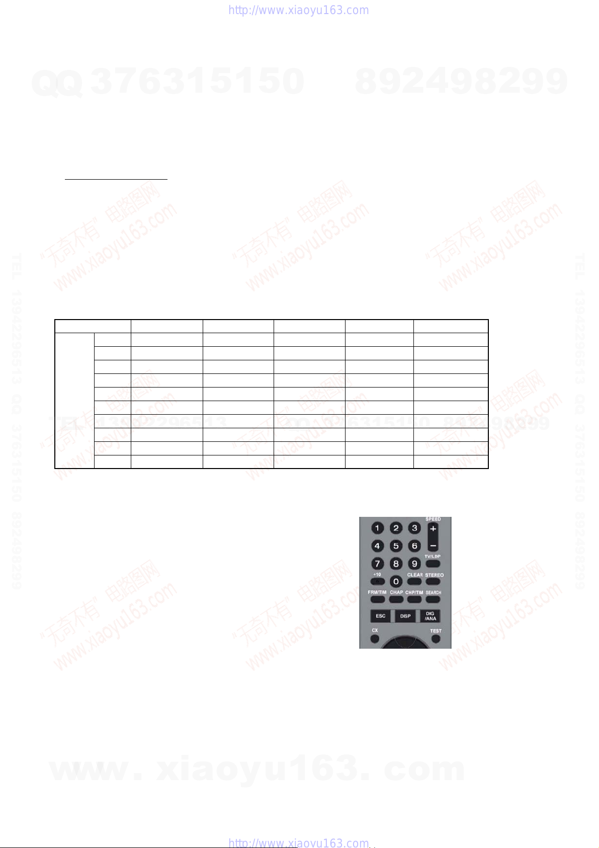
• Remote controller (RMT-D246A/D249P/D250P)
• Service remote controller (J-6090-203-A)
•Monitor
Model name delete method
1. T urn the main POWER ON.
2. Press the following buttons on the service remote controller in this order.:
“ESC” k “CHAP” k “1”
* Confirm that the above operation is performed in the state that the screen has exited all settings such as “Home Menu” or “Simple
Setting”.
3. T urn the main POWER OFF.
4. Turn the main POWER ON.
5. Find out the tentative model name from the Correspondence Table (Table 1) for the client machine. Then, enter the 4-digit “Input No.”
TEL 13942296513 QQ 376315150 892498299
on the screen using the service remote controller.
6. The model name setting method is complete. (Screen disappears.)
* Upon completion of the model name setting, be sure to press both “ENTER” and “3” simultaneously on the service remote controller
without fail. It sets the remote control code “3”.
3
7
6
3
1
5
1
5
0
8
9
2
4
9
8
2
9
9
TEL 13942296513 QQ 376315150 892498299
Table1 Correspondence table between tentative model name and final product name
Model name RDR-HX680 RDR-HX780 RDR-HX785 RDR-HX980 RDR-HX1080
AEP1 MRX-1730/CEK MRX-1735/EC1 MRX-1735/EC1 MRX-1755/EC1 MRX-1799/EC1
AEP2 MRX-1720/EC2 MRX-1730/EC2 — MRX-1750/EC2 —
AEP3 MRX-1730/CEK — — — —
Tentative
model
name
TEL
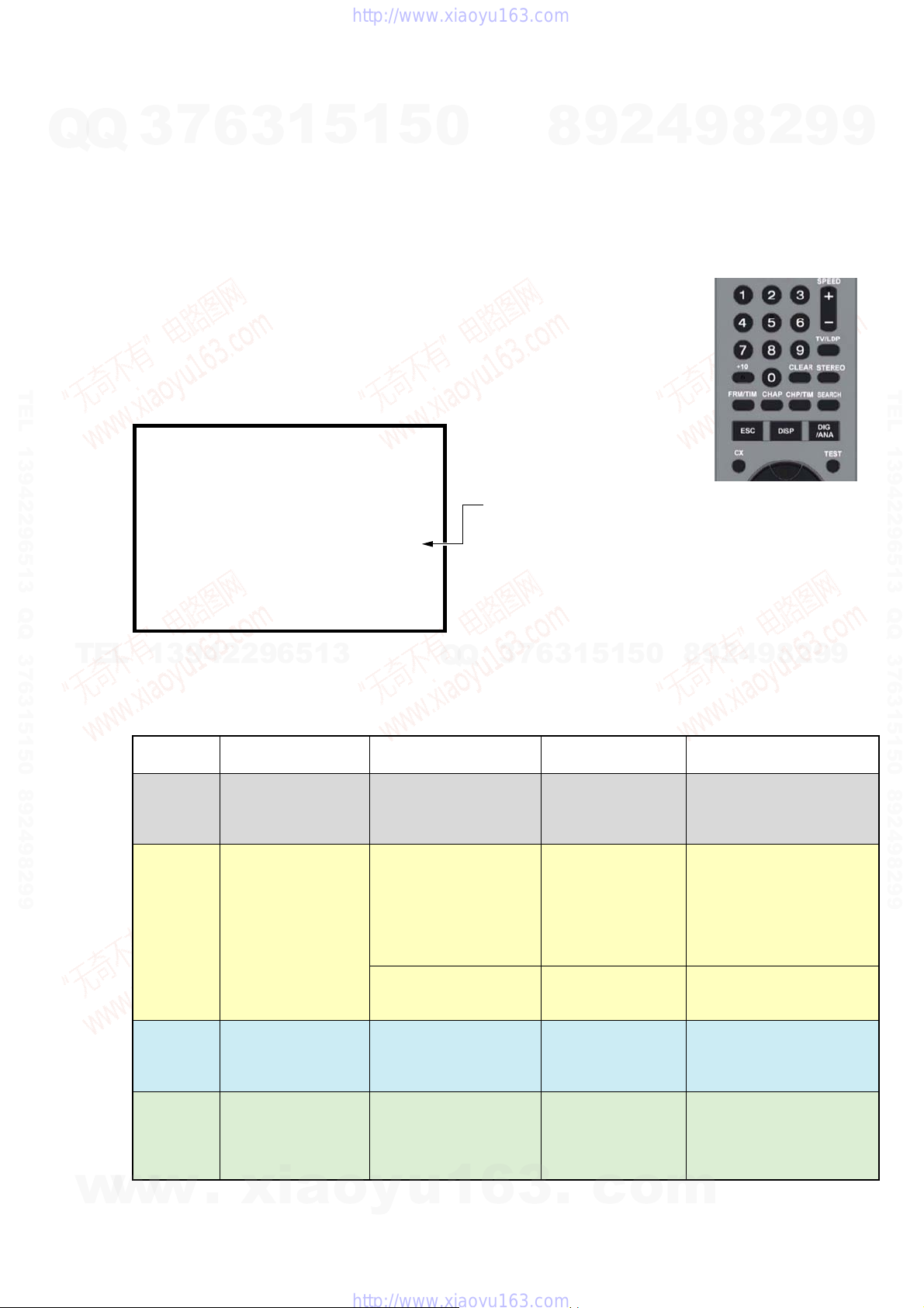
[Symptom]
If the following operation is performed, set won’t be able to be restored.
[Remedy]
Must not be performed the following operation using service remote.
If it is performed, set won’t be able to be restored.
And if set is broken by the operation, we can’t guarantee the set when
pressing in order of the following button.
UK — MRX-1730/CEK — — —
CND — MRX-1790/CA2 — — —
AUS — MRX-1730/AU2 — MRX-1750/AU2 —
RUS — MRX-1730/RU3 — MRX-1750/RU3 —
13942296513
SP — MRX-1730/SP7 — MRX-1750/SP7 —
TH — MRX-1730/SP7 — MRX-1750/SP7 —
E32 — MRX-1790/E32 — — —
Q
Q
3
1
5
1
3
6
7
Service remote controller
(Part code: J-6090-203-A)
5
0
8
9
2
4
9
8
2
9
9
* [ESC]--> [STEREO]
([ESC]--> [Any button which is not described in SM])
w
w
w
.
xia
o
y
u
1-2
1
6
3
.
c
o
m
MRX-1635/EC1 VERSION : 1.01
: RELEASE 104
Rev. 1. 5895
: 1.178 OK
: DVD-RW DVR-L12X OK
1.00 OK
: 000800004940
: XXXXXXXXXXXXXXXX 250
:
250
DEVICE : E2R-FEx1.0 FLASH : 64M
REGION : 2 C: 0000400259
HDCP : 0000400259
SYSCON
TUNERCON
DRIVE
PIC SERIAL
HDD INT
HDD USE
• Details on HDD data are described below:
Sample 1: (For the DVD recorder of 120GB)
HDD INT: XXXXXXXXXXXXXXXX 160
HDD USE: 120
Sample 2: (For the DVD recorder of 160GB)
HDD INT: XXXXXXXXXXXXXXXX 160
HDD USE: 160
Sample 3: (For the DVD recorder of 250GB)
HDD INT: XXXXXXXXXXXXXXXX 250
HDD USE: 250
Sample 4: (For the DVD recorder of 500GB)
HDD INT: XXXXXXXXXXXXXXXX 500
HDD USE: 500
The item [HDD USE] indicates the HDD capasity of the DVD recorder
specifications.
Check if the valeus match with the specifications of the DVD recorder.
Service remote controller
(Part code: J-6090-203-A)
4. HOW TO DIAGNOSE HDD FAILURE
7
Q
Q
TEL 13942296513 QQ 376315150 892498299
3
4-1. Defective HDD
There are four symptoms of defects in the HDD.
1. “E01” is displayed on the FLD.
(The HDD is unauthorized.)
2. “E02” is displayed on the FLD.
3. When playing a video, MP3, or JPG, contents freeze.
4. Irregular noises from the HDD
4-2. HDD Recognition status
How to enter Recognition status and sub screen mode.
• While the GUI screen is not displayed, use the service remote
controller and press “ESC” key followed by “DISP” key.
• While the first screen is displayed, press “DIG/ANA” key
repeatedly until the desired subscreen is displayed.
The subscreens change.
6
3
1
5
1
5
0
8
9
2
4
9
8
2
9
9
TEL 13942296513 QQ 376315150 892498299
TEL
w
13942296513
FL Display
REPAIR
E01
E02
Normal
w
w
.
OS Display
“Repaining the HDD”.
r
“HDD repair is
complete”.
An error occurred.
Please consult your
nearest Sony dealer.
Note that contents on
the HDD may be
erased when servicing
this unit.
The Hard Disk Drive
info is incorrect.
Use the Disk Setup
menu to reformat.
xia
5
1
5
1
3
6
7
3
Q
Q
HDD identification
conditions
Failure to physically
identify the HDD (no
connection, defective
HDD, interface error).
Physical identification of
HDD possible, but not
identified
Physical identification of
HDD possible, HDD
identified, but failure in
logical formatting.
Physical identification of
HDD possible, HDD
identified, and correct
logical formatting (HDD
correctly identified).
o
y
u
1
6
1-3
Details on HDD data
are described below.
Blank space
WDC 10234564 # 160
WDC 10234564 ! 160
WDC 10234564 160
3
.
c
o
0
m
9
2
8
9
4
2
9
8
Remarks
Check the connection to the
SATA cable and power cable.
Replace the SATA cable or
power cable.
Replace the HDD.
Replace the FE or part in the
SATA/ATA communication.
“#” indicates that the HDD is
unauthorized.
“!” indicates an HDD
authorization error. Initialize
the HDD.
9
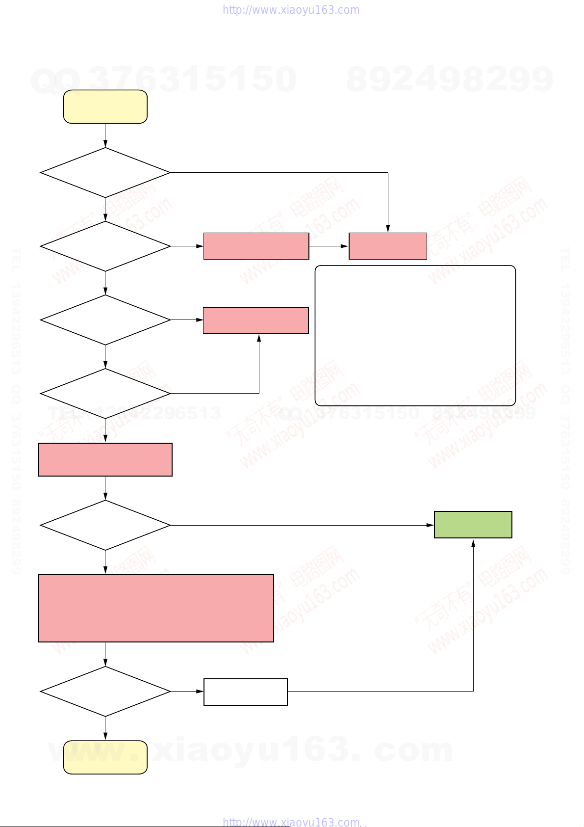
4-3. Display [E01] on FLD with unrecognized HDD
Q
Q
3
E01
7
6
3
1
5
1
5
0
8
9
2
4
9
8
2
9
9
Is the HDD free from
abnormal noises?
YES
TEL 13942296513 QQ 376315150 892498299
Is not “#” displayed?
YES
Reconnect the SATA
cable. Does the problem
still occur?
YES
Replace the SATA cable.
Does the problem
TEL
still occur?
13942296513
YES
NO
NO
NO
NO
Unauthorized HDD
Replace the SATA Cable
Q
Q
Note: Write down the HDD information on the HDD
7
3
Refer to “Note”.
0
*
8
9
2
4
9
8
Replace the HDD
return sheet before replacing the HDD.
Note the information on pages 6-6, 6-7, 6-9,
and 6-10 of Chapter 6, “SERVICE MODE”.
For information about replacing the HDD, see
page 2-5 of Chapter 2, “DISASSEMBLY”.
After replacing the HDD, perform
“Factory Check” on “SERVICE NOTE”, page 10.
When performing “Factory Check”, the data
saved to the HDD by the customer is erased.
Obtain customer consent before performing
“Factory Check”.
5
1
5
1
3
6
2
9
TEL 13942296513 QQ 376315150 892498299
9
Replace the HDD with a new
one and perform Factory Check.
Does the problem
still occur?
YES
There may be a problem with the Engine.
Therefore, put the original HDD back in the unit.
Then, follow the procedure to replace the Engine.
After replacing the Engine, perform “Setting the Model Name”
on “Service Note”, page 6.
Does the problem
still occur?
YES
Refer to “Note”.
*
NO
NO
Final check
Note: Performing “Final Check” will not erase the HDD data.
END
Note: Write down the HDD information on the HDD
return sheet before replacing the Engine.
For information about replacing the Engine,
see page 2-4 of Chapter 2, “DISASSEMBLY”.
When performing “Factory Check”, the data
saved to the HDD by the customer is erased.
Obtain customer consent before performing
“Factory Check”.
w
w
Another defect
w
has occurred.
.
xia
o
y
u
1
6
3
1-4
.
c
o
m
Q
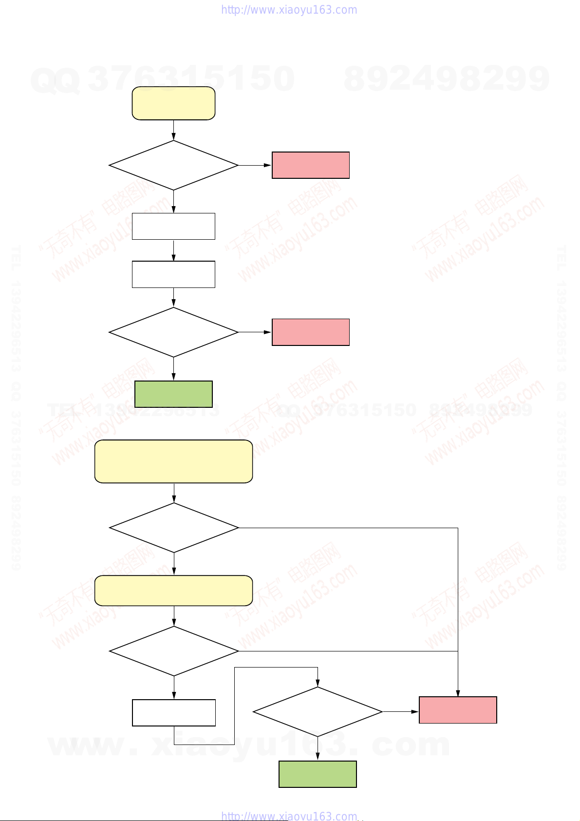
4-4. Display [E02] on FLD
7
Q
3
6
3
E02
1
5
1
5
0
Note: When E02 is displayed, the user data has
already broken due to system DATA Error.
8
9
2
4
9
8
2
9
9
Is the HDD free from
abnormal noises?
YES
Factory check
TEL 13942296513 QQ 376315150 892498299
Final check
Has the Final check ended
with success?
YES
END
TEL
13942296513
4-5. When playing a VIDEO, MP3, or JPG, the contents freeze
NO
Note: Performing “Final Check” will not erase the HDD data.
NO
Replace the HDD
Replace the HDD
7
3
Q
Q
Refer to “Note”.
*
Refer to “Note”.
*
1
3
6
5
1
5
0
8
9
2
4
9
8
2
9
TEL 13942296513 QQ 376315150 892498299
9
w
w
When playing a VIDEO, MP3, or JPG,
the contents freeze.
(Any error is not displayed on the FLD.)
Is the HDD free from
abnormal noises?
YES
Display the ATA/ATAPI history by using
“HDD Access Flow” on page 6-10.
Does the history show
no errors?
YES
Final check
Note: Performing “Final Check”
w
.
xia
will not erase the HDD data.
o
y
NO
NO
Has the Final check ended
with success?
u
1
6
END
YES
3
.
c
NO
o
Replace the HDD
Refer to “Note”.
*
m
1-5
4-6. Factory Check
1. Pull out and then reconnect the AC cable.
Q
Q
2. Press “ESC” key followed by “P.RUN” key to start Formatting.
3. When “B COMPLETE” appears, the Factory Check is complete.
4. Press “Power” button. The unit starts normally.
When “Factory Check” has finished completely without error, reset “Recording Error History” and “ATA/ATAPI History Error” with the
Clear key .
3
7
6
3
1
5
1
5
0
8
9
2
4
9
8
2
9
9
Recording Error History Display
07-03-19 12:36:06 ESFSYS INIT
07-03-19 12:36:06 HDD Zero MR
07-03-19 12:36:06 HDD Initialze
07-03-19 12:36:06 HDD Zero MR
07-03-19 12:27:27 Status NG
TEL 13942296513 QQ 376315150 892498299
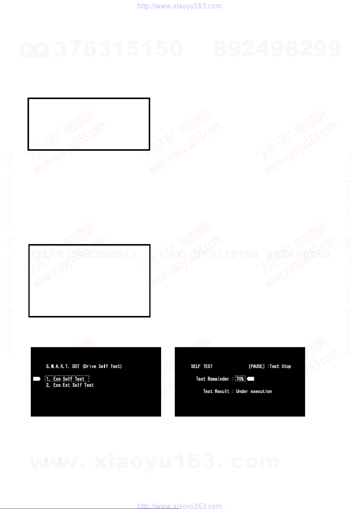
4-7. Final Check
4-7-1. SELF TEST (SMART TEST)
This is a simplified diagnosis for the HDD.
A serious failure in the HDD can be detected with this test.
Time required for testing: Approx. 60 sec.
How to start/terminate the diagnostic program
Use the remote control unit for servicing.
• How to start: Press the following keys in this order; “ESC”, “CX”, “0”, and “1” keys. (refer to 6-2-15)
• How to terminate: Press “ESC” key.
TEL
13942296513
HDD CHECK MODE [1-4]
1 HDD Information
2 S.M.A.R.T Attribute Information
3 S.M.A.R.T DST
4 HDD R/W Check
Note: Write down the HDD information on the HDD return sheet before
replacing the HDD.
Note the information on pages 6-6, 6-7, 6-9, and 6-10 of Chapter 6,
“SERVICE MODE”.
When performing “Factory Check”, the data saved to the HDD by the
customer is erased.
Obtain customer consent before performing “Factory Check”.
“Recording Error History” and “A T A/ATAPI History Error”, see pages
6-9, 6-10 of Chapter 6, “SERVICE MODE”.
7
3
Q
Q
6
3
1
5
1
5
0
8
9
2
4
9
8
2
9
TEL 13942296513 QQ 376315150 892498299
9
Execute Self-Test.
• Press “3” key on the remote control unit for servicing while the menu screen is displayed.
• When the following screen is displayed, press “1” key to start the Self-Test.
Note: Performing “Self Test” will not erase the HDD data.Note: “2. Exe Ext Self Test” is not used.
w
w
w
.
xia
o
y
u
1
6
3
1-6
.
c
o
m
Q
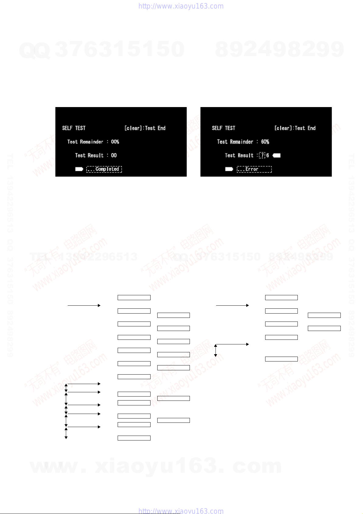
Diagnosis results
•Without an error: “. . . Completed” is displayed.
Q
3
Then, proceed to the Extended Self-Test.
•With an error: “. . . Error” is displayed. Look at the number in Test Result.
If the place value for tens is 1 or 2, execute the Self-T est again.
If it is from 3 to 7, the HDD must be replaced.
Note: If the result of the second test is the same, replacement of the HDD is required.
7
1
5
1
6
3
Example: No error Example: With an error
5
0
8
9
2
4
9
8
2
9
9
TEL 13942296513 QQ 376315150 892498299
4-7-2. Performance Check
Press “ESC” key, then “A.MON” key.
This is a reading test across all sectors of the HDD.
Data recorded on the HDD will not be erased, because no writing operation is performed.
Time required for testing: Approx. 45 min/160 G
75 min/250 G
130 to 150 min/500 G
TEL
When “Performance Check” finishes completely without error, reset “ATA/ATAPI History Error” with the Clear key.
13942296513
FL display specification
HDD factory Check HDD performance Check
aNormal display aError display
0:Factory Check start 0 0 000000
Power On
1:Power ON Test
2:
Random Write/Read/Compare Test
3:ID Sequential Read Verify Test
4:
OD Sequential Read Verify Test
5:Format
6:Power OFF Test
Power off
Power On15s
20s
Power off
Power On
15s
20s
Power off
15s
1 0 000000 81 0 00000
2 0 000000
3 **
*****
H M S
4 **
*****
H M S
5 FM
*****
H M S
6 0 000000
7 0 000000
8 0 000000
9 0 000000
A 0 000000
B COMPLETE
HDD ERR 01
HDD ERR 02
HDD ERR 03
HDD ERR 04
HDD ERR 05
HDD ERR 07
HDD ERR 09
Q
Q
7
3
80:Performance Check start
81:Power ON Test
82:
83:Power OFF Test
15s
84:Complete
7:Power ON Test
8:Power OFF Test
9:Power ON Test
a:Power OFF Test
b:Complete
0
5
1
5
1
3
6
Power On
all Sequential Read Verify Test
Power off
4
2
9
8
aNormal display
80 0 00000
82**
*****
H M S
83 0 00000
H M S
84 COMPLETE
8
9
aError display
HDD ERR 81
HDD ERR 82
2
9
TEL 13942296513 QQ 376315150 892498299
9
w
w
Fig 1. FL Display Flow
* The logo for “Factory Check” and “Performance Check” is recorded in “ATA/ATAPI History Error”.
w
.
xia
o
y
u
1
6
3
1-7E
.
c
o
m
Q
SECTION 2
DISASSEMBLY
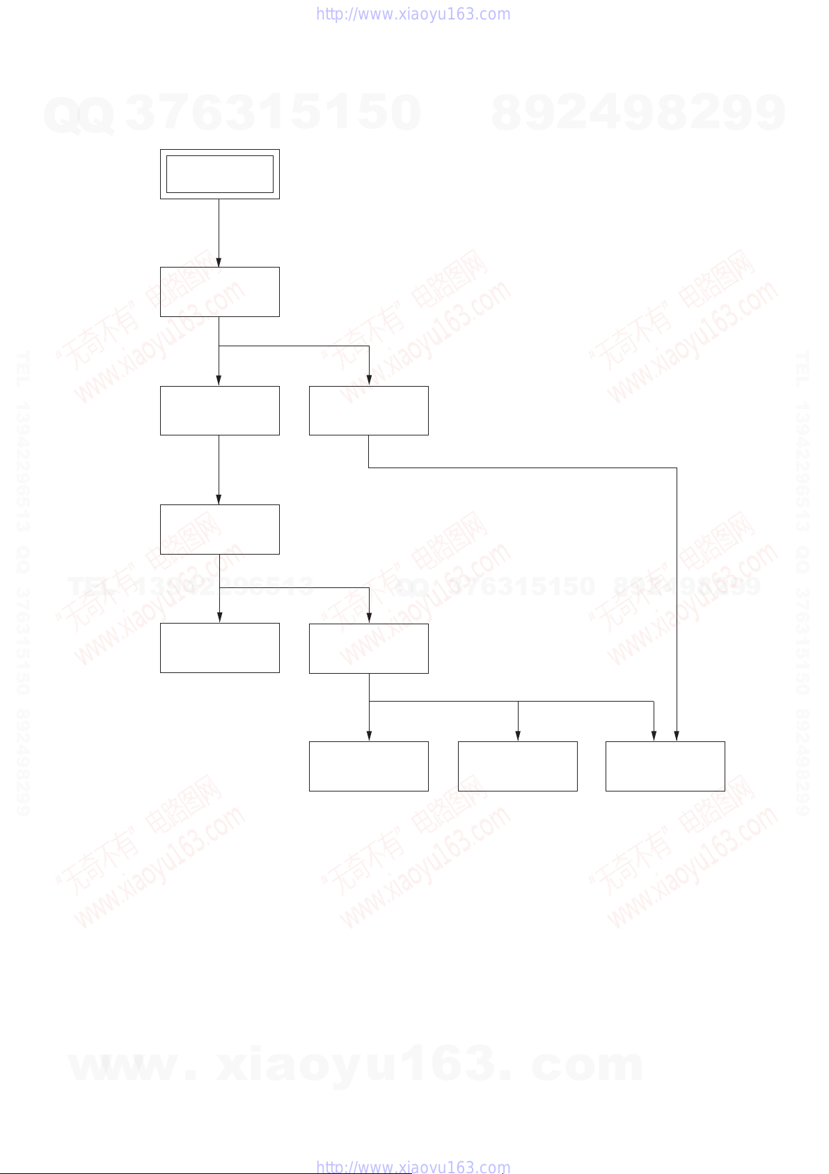
NOTE: The following flow chart shows the disassembly procedure.
Q
3
7
6
Set
Upper case
(Page 2-1)
3
1
5
1
5
0
RDR-HX680/HX780/HX785/HX980/HX1080
8
9
2
4
9
8
2
9
9
TEL 13942296513 QQ 376315150 892498299
TEL
Tray cover assembly
(Page 2-2)
Front panel block
(Page 2-3)
13942296513
FR-291 board,
FL-184 board
(Page 2-4)
HDD unit
(Page 2-7)
DVD unit
(Page 2-5)
Q
Q
3
7
6
3
1
5
1
5
0
8
9
2
4
9
8
2
9
TEL 13942296513 QQ 376315150 892498299
9
w
w
w
.
xia
DC fan
(Page 2-6)
o
y
u
1
6
3
2-1
Switching regulator
(Page 2-9)
.
c
o
AV-133/134 board
(Page 2-8)
m
)
NOTE: Follow the disassembly procedure in the numerical order given.
7
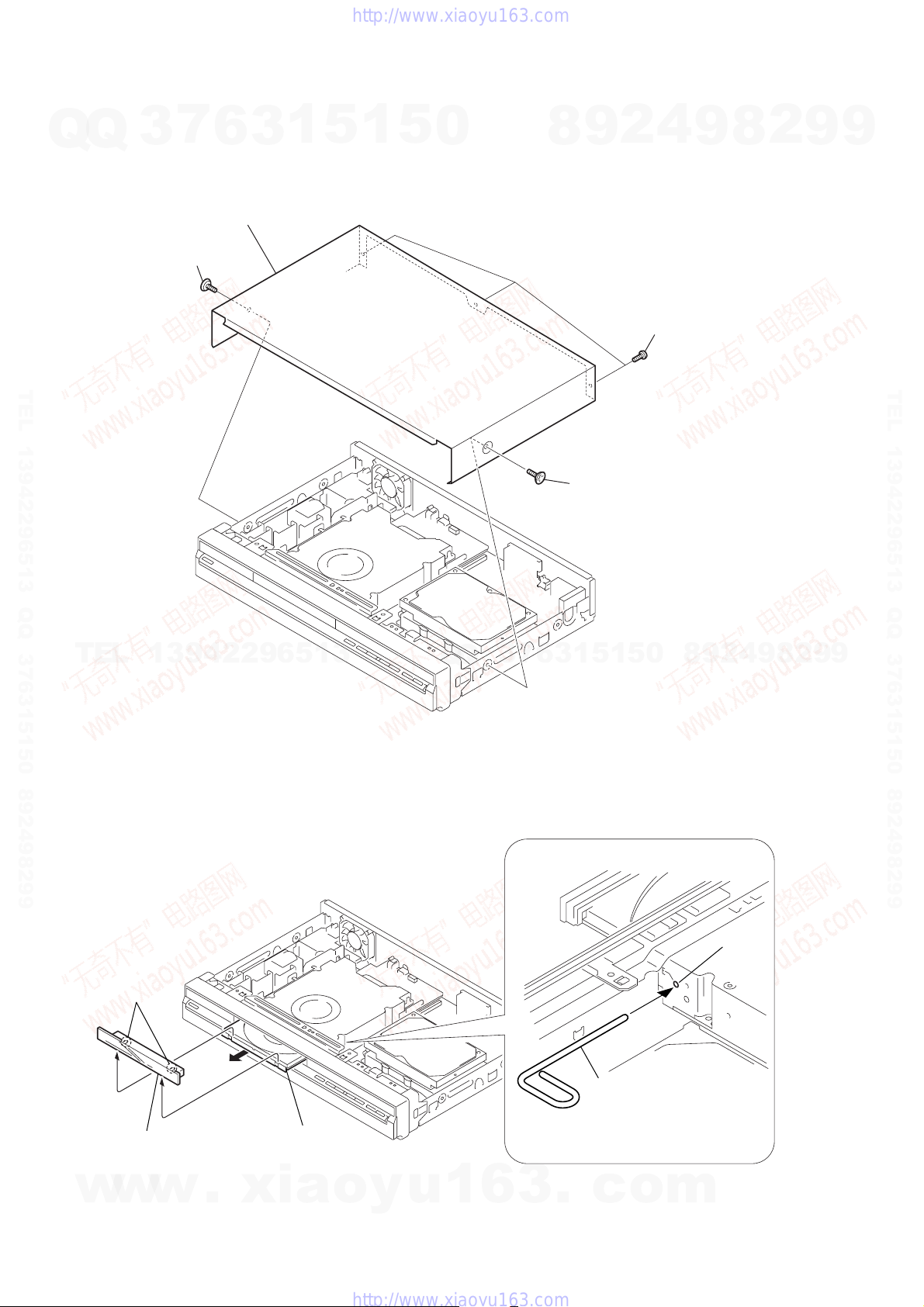
2-1. UPPER CASE
Q
Q
3
2
Tapping screw
4
Upper case
6
3
1
5
1
5
0
2
9
8
3
Three screws
(special front point screw
4
9
8
2
9
9
TEL 13942296513 QQ 376315150 892498299
TEL
2-2. TRAY COVER ASSEMBLY
13942296513
Q
Q
3
7
6
1
Tapping screw
1
3
5
1
5
0
8
9
2
4
9
8
2
9
TEL 13942296513 QQ 376315150 892498299
9
3
Two claws
4
Tray cover assembly
w
w
w
.
xia
2
Open the tray
o
y
u
1
6
3
2-2
.
1
The stiff wire
c
o
Hole
m
s
Q
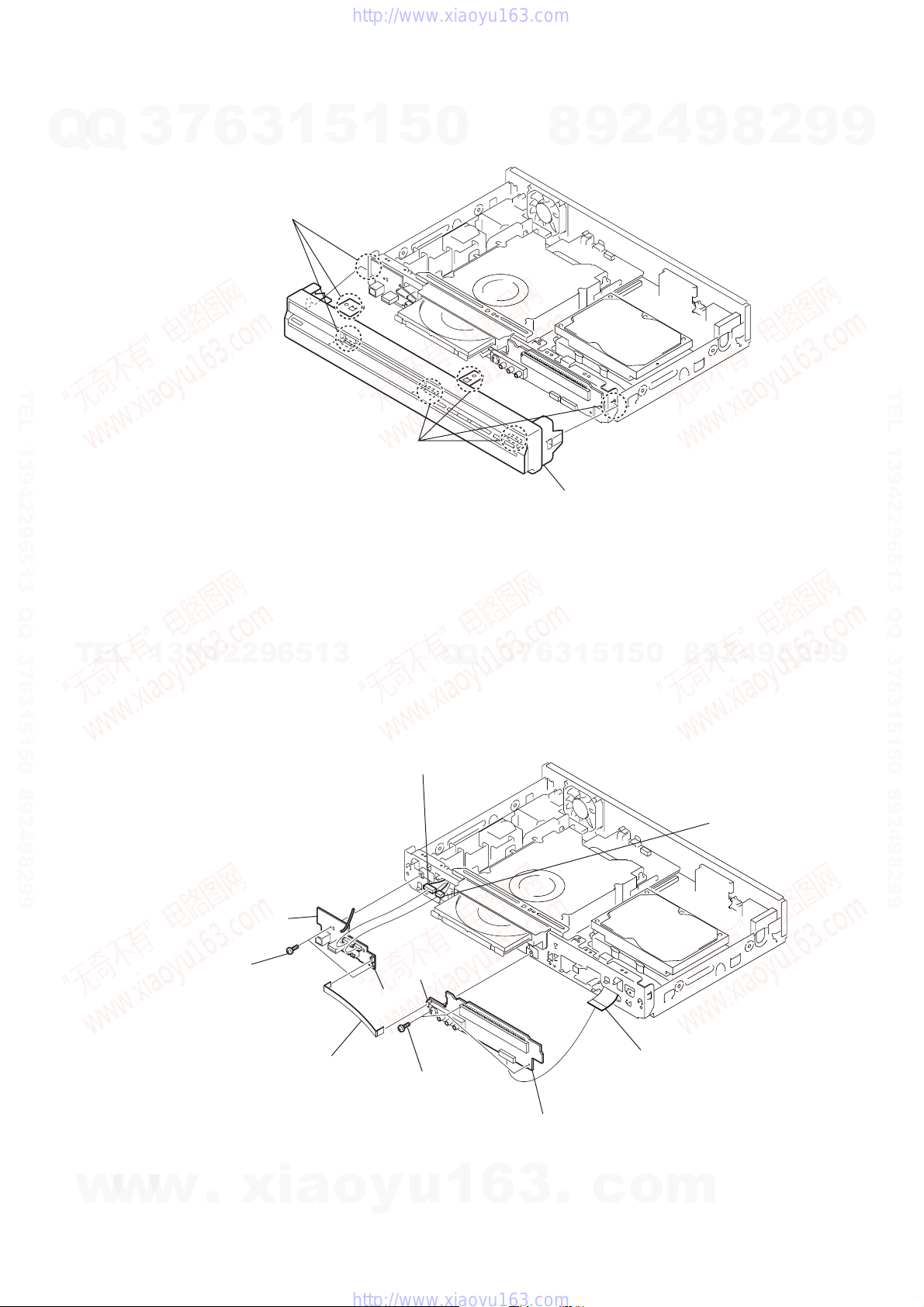
2-3. FRONT PANEL BLOCK
Q
3
7
6
1
1
3
Three claws
5
1
5
0
8
9
2
4
9
8
2
9
9
TEL 13942296513 QQ 376315150 892498299
2
Four claws
TEL
13942296513
2-4. FR-291 BOARD, FL-184 BOARD
2
RU-001 harness
(10p) (CN102)
Q
Q
3
7
3
Front panel block
1
3
6
5
1
5
0
2
9
8
3
RV-003 harnes
(6p) (CN101)
4
9
8
2
9
TEL 13942296513 QQ 376315150 892498299
9
w
w
4
Two screws
(+BV3)
w
5
FL-184 board
1
FLR-010 flexible
flat cable (5core)
.
xia
(CN201)
(CN106)
6
Three screws
(+BV3)
8
o
y
u
1
6
3
2-3
FR-291 board
.
c
7
FAR-008 flexible flat cable
(24core) (CN202)
o
m
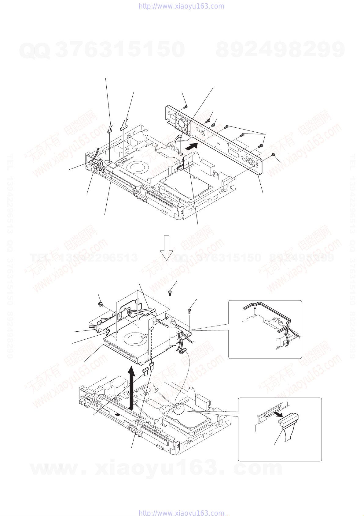
2-5. DVD UNIT
Q
Q
3
7
6
3
(4p) (CN203)
1
3
PH-080 harness
4
(13p) (CN201)
5
1
5
0
PR-078 harness
7
Screw (+P3)
4
2
9
8
5
RH-059 or RH-060 harness
(7p) (CN5604)
8
Screw (+BV3)
9
Screw (+P3 × 4)
8
9
0
Five screws (+BV3)
2
9
9
TEL 13942296513 QQ 376315150 892498299
1
RU-001 harness
(10p) (CN102)
2
RV-003 harness
(6p) (CN101)
Power supply block
TEL
13942296513
w;
RP-078 harness
qk
Two screws
(+PSW3
(13p) (CN4501)
×
6)
Q
Q
qf
(+BV3)
A
6
Flexible flat cable (40core)
(CN2301)
7
3
Four screws
qg
Two screws
(+BV3)
6
3
qs
Remove the rear panel in
the direction of the arrow
0
5
1
5
1
qa
Screw (+P3 × 4)
2
9
8
4
9
A
.
8
2
9
TEL 13942296513 QQ 376315150 892498299
9
ql
Holder
wd
Remove the Gusket
(for Canadian model only)
wf
Remove the DVD unit in
the direction of the arrow
ws
RU-001 harness
(10p) (CN5201)
w
w
w
.
B
.
xia
B
wa
RV-003 harness
(6p) (CN5101)
o
y
u
2-4
1
6
3
.
qh
Remove the harnesses.
qj
Remove the PH-080
harness (4p)
c
o
m
Q
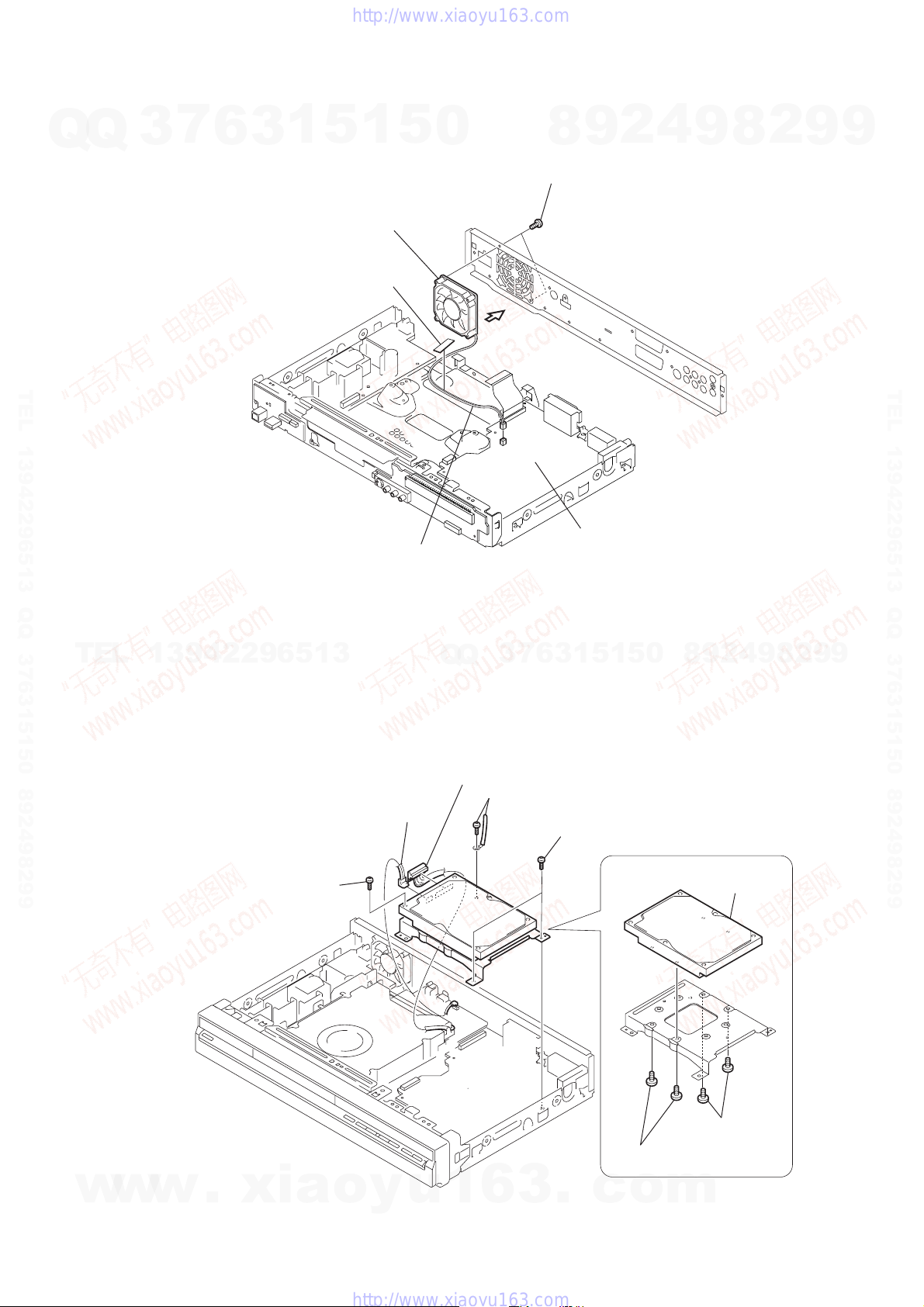
2-6. DC FAN
Q
3
7
6
3
1
5
1
4
DC fan
2
Non-halogene tape
5
0
Air flow
9
8
3
Two screws
(+BV3)
2
4
9
8
2
9
9
TEL 13942296513 QQ 376315150 892498299
1
Fan harness
(2p) (CN201)
TEL
13942296513
2-7. HARD UNIT
5
(7pin) (power)
4
PH-080 harness
(4pin) (data)
7
3
Q
Q
RH-059 or RH-060 harness
3
Screw (+BV3)
and wire clamp
AV-133/134 board
5
1
3
6
1
Two screws (+BV3)
1
5
0
8
9
2
4
9
8
2
9
TEL 13942296513 QQ 376315150 892498299
9
w
w
w
2
.
xia
Screw (+BV3)
o
y
u
1
6
3
2-5
.
7
6
Two screws
6-32UNCX4 (SG)
c
6-32UNCX4 (SG)
o
m
8
HDD unit
Two screws
s
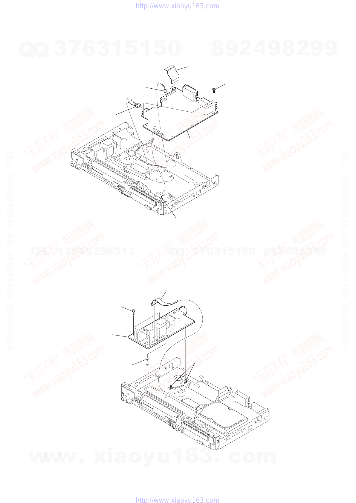
2-8. AV -133/134 BOARD
7
Q
Q
TEL 13942296513 QQ 376315150 892498299
3
6
4
PAE-003 harness
(5p) (CN301)
3
1
5
1
3
Fan harness
(2p) (CN201)
5
0
6
board
2
FRA-006 flexible flat cable
(40core) (CN101)
AV-133/134
8
2
9
5
Three screw
(+BV3)
4
9
8
2
9
9
TEL 13942296513 QQ 376315150 892498299
TEL
2-9. SWITCHING REGULATOR
13942296513
2
Three screws (+BV3)
5
Switching regulator
4
Spacer
1
FAR-008 flexible flat cable
(24core) (CN105)
7
3
Q
Q
1
PAE-003 harness
(12p) (CN202)
3
Two board holders
6
3
1
5
1
5
0
8
9
2
4
9
8
2
9
9
w
w
w
.
xia
o
y
u
1
6
3
2-6
.
c
o
m
Q
2-10.CIRCUIT BOARDS LOCA TION
Q
3
7
6
Switching Regulator
3
1
5
1
5
0
RD-066 board
POWER, EMMA, VIDEO/AUDIO, MEMORY,
SATA/IDE IF, HDMI/DV/USB, DVD DRIVE
8
9
2
4
9
8
2
9
9
TEL 13942296513 QQ 376315150 892498299
RL-184 board
DV, USB,
REMOCON RECEIVER
FR-291 board
FL DRIVER, LINE 2 IN
FUNCTION SW
TEL
13942296513
Q
Q
3
7
AV-133/134 board
IT CONTROLLER, IR, POWER, FAN CONT,
VIDEO/AUDIO, EURO, TUNER
2
8
9
4
2
9
8
0
5
1
5
1
3
6
9
TEL 13942296513 QQ 376315150 892498299
9
w
w
w
.
xia
o
y
u
1
6
3
2-7E
.
c
o
m
SECTION 3
BLOCK DIAGRAMS
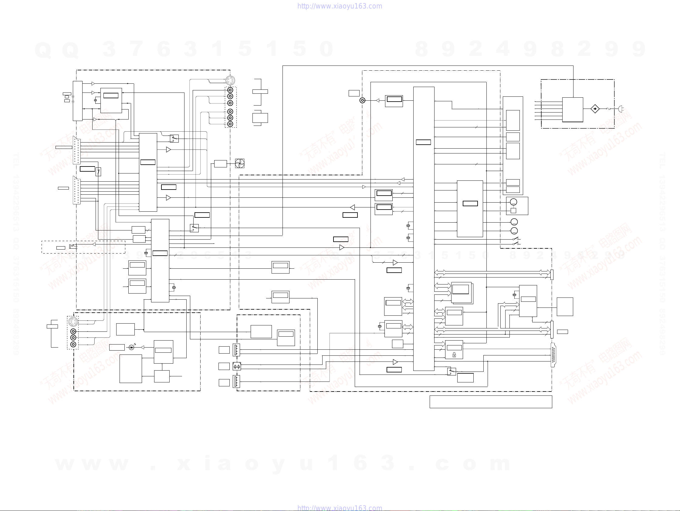
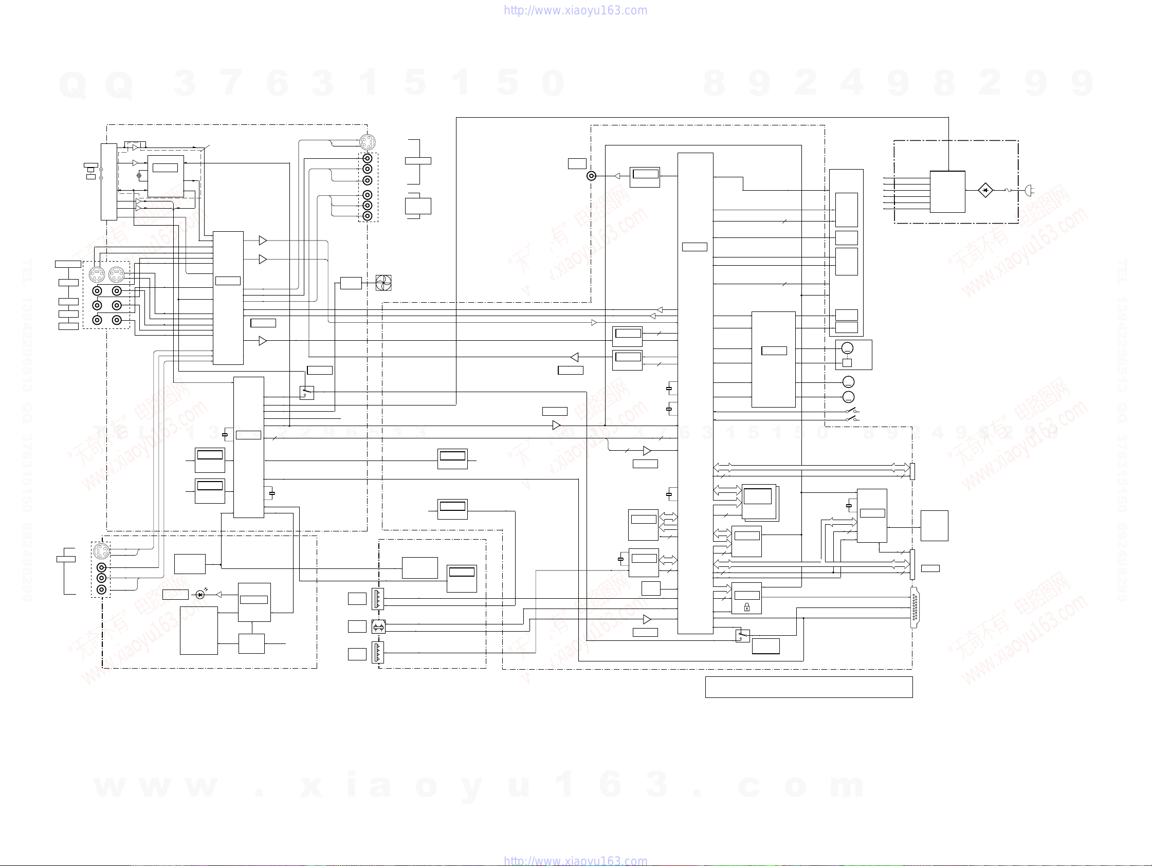
3-1. OVERALL BLOCK DIAGRAM-1
IC101 VDD
D212,214
HDD,DVD
MSPSTAT
V+5V
S201-S210
FUNCTION
TU_V
XRST1
TU_L
TU_R
3
SWITCH
FLUORESCENT
DISPLAY
7
SDA
SCL
2Y,2C
2V
2L,2R
FANCTION
N-LINK
IC103
IC101 VDD DET
IC102
POWER FAIL
DET
ND201
IC401
VIDEO / AUDIO
SELECTER
AGC, MSPSTAT
SW
X101
15MHz
9
KEY1-3
KEY1-3
SEG1-16
GRD1-12
F1,F2
2
4
6
YP,CR,,CB
Y,C
L,R
IC101
IT
CONTROLLER
IC201
FL DRIVE
VEE
Q201,202
T201
DC/AC
CONVERTER
3
R
C
Y,C
V
PY,PB,PR
IC402
BUFFER
SDA
SCL
P-CONT
FANCTL
6 4
2
2
9
MRST
CEC, HPD
X102
32.768KHz
FLDATA
FLCLK
FLSTB
V+12V
Q
TEL 13942296513 QQ 376315150 892498299
HX780 : AEP1/HX785/
HX980 : AEP1/
HX1080 : AEP1
Q
(HX680/HX780: AEP, UK, RUS/HX785/HX980: AEP, RUS/HX1080)
U601
TUNER
AERIAL
IN
18.432MHz
41
R,G,B IN R,G,B
V/Y,C IN/OUT
L,R IN
L,R IN
FANCTION
N-LINK
22
IC406
AVLTH SW
20
R,G,B OUT
V/Y,C IN/OUT
V/Y,C OUT
L,R IN
L,R OUT
FANCTION
N-LINK
1
E
L
J201
2Y
2C
2V
2L
2R
FR-291 BOARD
LINE2 IN
JA501(2/2)
LINE 1/DECODER
JA501(1/2)
LINE 3-TV
JA751
G LINK
T
S VIDEO
VIDEO
AUDIO L
(MONO)
AUDIO R
OUT
3
AV-133 BOARD
X1601
SIF
SDA
SCL
AGC
IC1601
EURO MSP
1
IC104
DDC SW
1
B,G
R/C
Y
L,R
L,R
6
JA402
DRIVE
P CONT2
5
RDR-HX680/HX780/HX785/HX980/HX1080
5
JA401
Y
C
V
L
R
PY
PB
PR
FAN
CN104
USB
ATYPE
CN105
USB
BTYPE
CN103
DV
IN
S VIDEO
VIDEO
AUDIO L
AUDIO R
Y
CB
CR
FAN
DSDA,DSCL
1
FL-184 BOARD
KEY1,3
IR
3
USBDM2
USBDP2
V+5USB
USBDM1
USBDP1
USBVFB
TPAP,TPAN
TPBP,TPBN
LINE2 OUT
COMPONENT
VIDEO
OUT
EV+5.8V
S101
POWER
S102
ONE TOUCH DUB
1
IC3707
IC5204
RESET
5V REG
IC101
REMOTE
CONTORL
RECEIVE
5
V+1R5_IN
0
Q
IC3702
Y/C,RGB
IC3202
AUDIO LPF
42
Q
JA5701
DIGITAL
OUT
RD-066 BOARD
YP,CR,CB
Y,C
IC3101
L,R
AUDIO ADC
L,R
IC3201
AUDIO DAC
3
2
X5101
24.576MHz
IC5701
SPDIF SEL
7
IC3701
IC201
64Mbit
SDRAM
IC5103
DV PHY
IC5203
16.9344MHz
24.576MHz
X5201
48MHz
XTAL OSC
X101
X1001
AIBD0
AOD0
6
X1002
27MHz
XRESETXRST1
4
5
MD0-15
MA0-11
PHY D0-7
SPDIF
8
7
8
IC1001
AV ENC/DEC
3
1
SO, SI, SCLK
FDRV
MDRV
XDMUTE1
XDMUTE2
FG
SL1,SL2
LD
OPEN
CLOSE
DDATA0-31
DADRS0-12
HDATA0-15
HADRS1-22
9
5
13
17
IC1102
FLASH ROM
3
13
IC5801
W2EN+,W2EN-,
W3EN+,W3EN-,
W1EN+,W1EN-,
OSCEN+,OSCEN-
FMO+, FMO-
RF+,RFA, B, C, D, S1, S2, S3, S4
TRACKING COIL DRIVE
SPINDLE MOTOR DRIVE
SLED MOTOR DRIVE
LOADING MOTOR DRIVE
1
IC1201
IC1221
512Mbit x2
DDR SDRAM
128Mbit
IC5803
IC5804
2
IC501
FOCUS COIL DRIVE
5
AT0DAT10-15 AT0DAT10-15
XRESET
AT1DAT10-15 AT1DAT10-15
TXD,RXD
XRESET
DDC SW
4
DVD
OPTICAL
SI, SCLK
5
4
XRESET
U,V,W
HU+,HU-
HV+,HVHW+,HW-
ST1+,ST1-,
ST2+,ST2-
LDO+,LDO-
0
PICK-UP
BLOCK
LD
DRIVER
LASER
FRONT
MONITOR
PHOTO
DETECTOR
TRACKING
T+,T-TDRV
F+,F-
COIL
FOCUS
COIL
M
H
M
M
8
XRESET
X5502
25MHz
AT1DAT10-15
13
SPINDLE
MOTOR
MOTOR
LOADING
9
SLED
MOTOR
OPEN
CLOSE
9
IC5602
SATA
BRIDGE
P-CONT
SWITCHING
REGULATOR
2
TXP,TXN
RXP,RXN
JA5801
8
V+12V
EV+5.8V
V12M
V+5M
SW+3.3V
SW+1.53V
4
13
2
13
(not use)
CN3802
IDE HDD
HDD
UNIT
SWITCHING
REGULATOR
9
2
8
D101-104
RECT
2
9
FU101
T3.15A
250V
9
9
AC IN
TEL 13942296513 QQ 376315150 892498299
9
w
w
w
.
Note: The HDMI block is highly confidential, and prohibited from releasing to public.
The components identified by mark 9 contain confidential information.
Strictly follow the instructions whenever the components are repaired and/or replaced.
x
i
a
o
y
u
1
6
3
.
c
o
m
3-1 3-2
RDR-HX680/HX780/HX785/HX980/HX1080
3-2. OVERALL BLOCK DIAGRAM-2
IC1601
EURO MSP
C1
Y1
V1
L1
R1
Y3
C3
V3
L3
R3
3
IC101 VDD
V+5V
D212,214
HDD,DVD
MSPSTAT
1
S201-S210
FUNCTION
SWITCH
TU_V
XRST1
FLUORESCENT
Q
TEL 13942296513 QQ 376315150 892498299
JA403
*
LINE1/LINE3
S VIDEO
VIDEO
AUDIO L
AUDIO R
LINE2 IN
S VIDEO
VIDEO
AUDIO L
(MONO)
AUDIO R
Q
(HX780: AUS, TH, SP, CND, E/HX980: AUS, TH, SP)
AV-134 BOARD
U601
TUNER
AERIAL
OUT
IN
T
J201
SIF
X1601
18.432MHz
SDA
SCL
AFT
AGC
JA403
*
6P RDR-HX780: CND, E model
3P RDR-HX780: AUS, TH, SP
/HX980: AUS, TH, SP model
E
L
2Y
2C
2V
2L
2R
FR-291 BOARD
TU_L
TU_R
TU_L/R
SDA
SCL
ND201
DISPLAY
EXCEPT
HX780: Canadian, E
R,G,B
2Y,2C
2V
2L,2R
AFT, AGC, MSPSTAT
X101
15MHz
3
IC103
IC101 VDD DET
IC102
POWER FAIL
DET
KEY1-3
7
IC401
VIDEO / AUDIO
SELECTER
9
KEY1-3
SEG1-16
GRD1-12
F1,F2
YP,CR,,CB
Y,C
IC101
IT
CONTROLLER
IC201
FL DRIVE
VEE
Q201,202
T201
DC/AC
CONVERTER
JA402
DRIVE
P CONT2
6
Y
C
V
L
R
PY
PB
PR
FAN
CN104
USB
ATYPE
CN105
USB
BTYPE
CN103
DV
IN
1
6
Y,C
V
PY,PB,PR
IC402
BUFFER
SDA
SCL
P-CONT
FANCTL
4
2
6 4
MRST
CEC, HPD
32.768KHz
FLDATA
FLCLK
FLSTB
3
C
Y
L,R
L,R
IC104
DDC SW
2
9
X102
V+12V
JA401
S VIDEO
VIDEO
AUDIO L
AUDIO R
CB
CR
FAN
DSDA,DSCL
5
FL-184 BOARD
KEY1,3
Y
1
IR
5
USBDM2
USBDP2
V+5USB
USBDM1
USBDP1
USBVFB
TPAP,TPAN
TPBP,TPBN
LINE2 OUT
COMPONENT
VIDEO
OUT
3
EV+5.8V
S101
POWER
S102
ONE TOUCH DUB
1
IC3707
RESET
IC5204
5V REG
IC101
REMOTE
CONTORL
RECEIVE
V+1R5_IN
5
0
IC3702
Y/C,RGB
IC3202
AUDIO LPF
42
Q
JA5701
DIGITAL
OUT
Q
RD-066 BOARD
YP,CR,CB
Y,C
IC3101
L,R
AUDIO ADC
L,R
IC3201
AUDIO DAC
3
2
X5101
24.576MHz
IC5701
SPDIF SEL
IC3701
IC201
64Mbit
SDRAM
IC5103
DV PHY
IC5203
16.9344MHz
24.576MHz
X5201
48MHz
XTAL OSC
X101
X1001
AIBD0
AOD0
7
X1002
27MHz
XRESETXRST1
4
5
MA0-11
PHY D0-7
MD0-15
SPDIF
7
0
X5502
25MHz
AT1DAT10-15
DETECTOR
XRESET
4
DVD
OPTICAL
PICK-UP
BLOCK
LD
DRIVER
LASER
FRONT
MONITOR
PHOTO
TRACKING
COIL
FOCUS
COIL
M
H
M
M
13
SPINDLE
MOTOR
MOTOR
LOADING
SLED
MOTOR
OPEN
CLOSE
8
IC5602
BRIDGE
SATA
9
P-CONT
SWITCHING
REGULATOR
9
TXP,TXN
RXP,RXN
JA5801
V+12V
EV+5.8V
V12M
V+5M
SW+3.3V
SW+1.53V
2
13
2
13
(not use)
CN3802
IDE HDD
8
SWITCHING
REGULATOR
4
HDD
UNIT
2
SI, SCLK
5
4
XRESET
T+,T-TDRV
F+,F-
IC501
1
XRESET
XRESET
U,V,W
HU+,HU-
HV+,HVHW+,HW-
ST1+,ST1-,
ST2+,ST2-
LDO+,LDO-
5
AT0DAT10-15 AT0DAT10-15
AT1DAT10-15 AT1DAT10-15
SO, SI, SCLK
FDRV
FG
SL1,SL2
LD
OPEN
CLOSE
DDATA0-31
DADRS0-12
3
1
13
17
13
9
W2EN+,W2EN-,
W3EN+,W3EN-,
W1EN+,W1EN-,
OSCEN+,OSCEN-
5
IC1201
IC1221
IC1102
128Mbit
FLASH ROM
IC5801
FMO+, FMO-
DDR SDRAM
RF+,RFA, B, C, D, S1, S2, S3, S4
TRACKING COIL DRIVE
FOCUS COIL DRIVE
SPINDLE MOTOR DRIVE
SLED MOTOR DRIVE
LOADING MOTOR DRIVE
512Mbit x2
TXD,RXD
IC5803
IC5804
DDC SW
8
IC1001
AV ENC/DEC
MDRV
XDMUTE1
XDMUTE2
3
6
8
HDATA0-15
HADRS1-22
9
2
D101-104
RECT
8
FU101
T3.15A
250V
2
9
AC IN
9
9
TEL 13942296513 QQ 376315150 892498299
9
w
w
w
Note: The HDMI block is highly confidential, and prohibited from releasing to public.
The components identified by mark 9 contain confidential information.
Strictly follow the instructions whenever the components are repaired and/or replaced.
.
x
i
a
o
y
u
1
6
3
.
c
o
3-3 3-4
• Abbreviation
AUS : Australian model
CND : Canadian model
SP : Singapore model
TH : Thailand model
m
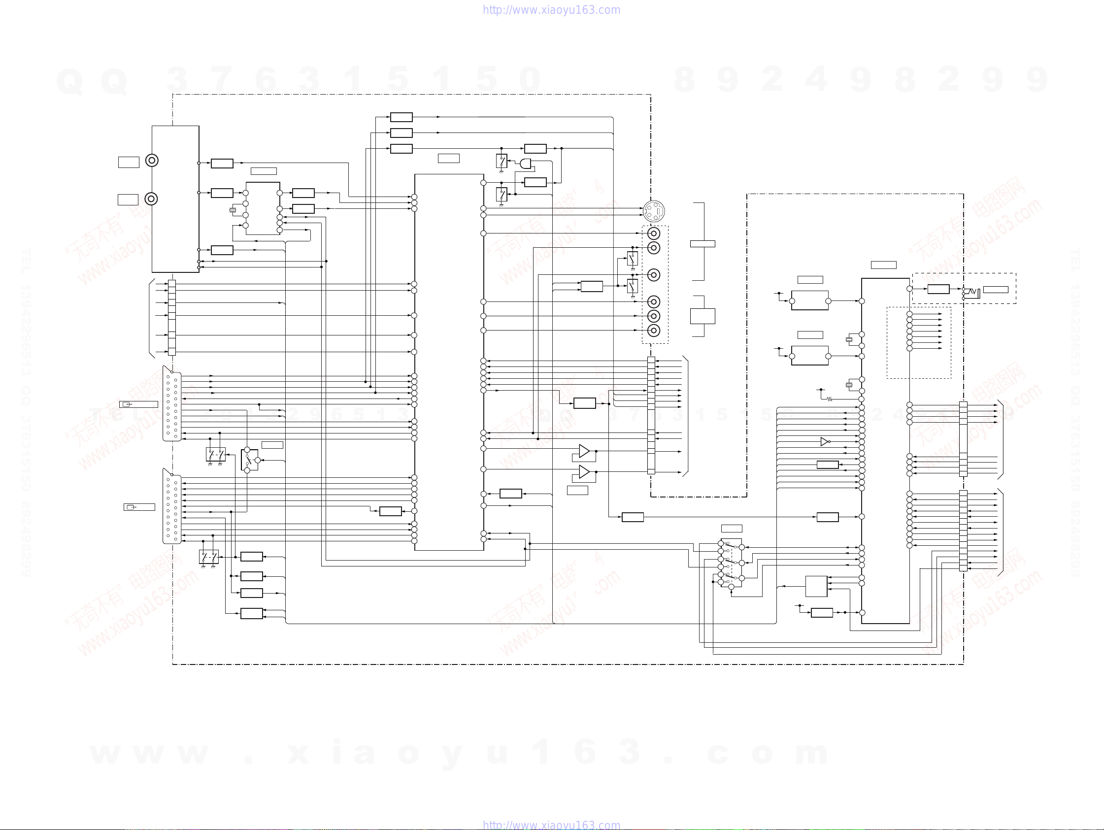
3-3. AV-133 BLOCK DIAGRAM (HX680/HX780: AEP, UK, RUS/HX785/HX980: AEP, RUS/HX1080)
Q
Q
3
7
6
3
1
AV-133 BOARD
U601
TUNER
AERIAL
IN
AERIAL
OUT
TEL 13942296513 QQ 376315150 892498299
FROM
FR-291 BOARD
(CN202)
(SEE PAGE 3-7)
JA501 (2/2)
LINE1-DECODER
T
E
L
JA501 (1/2)
LINE1-TV
2L
2R
2Y
2C
SDET2
2V
VIDEO OUT
SIF OUT
AGC OUT
Y2 IN
21
C2 IN
24
SDET2
23
2VIN
19
L2_LIN
17
L2_RIN
15
CN105(1/2)
41
41
42
36
32
28
40
37
31
29
27
1
23
24
22
22
20
20
21
19
15
11
7
16
10
8
6
2
3
1
1
SDA
SCL
V/Y IN
R/C IN
G IN
B IN
V/Y OUT
BLANKING_IN
N-LINK
FUNCTION
L IN
3
R IN
L OUT
R OUT
V/Y_IN
V/Y_OUT
R/C_OUT
G_OUT
B_OUT
BLANKING_OUT
N-LINK
FUNCTION
L_IN
R_IN
L_OUT
R_OUT
Q506
Q507
X601
18.432MHz
Q601
BUFFER
Q606
Q602
BUFFER
AMP
9
2
5
6
22
4
2
1
Q508
SAMUTE
Q505
SW
Q503,504
SW
Q501,502
FUNCTION
SW
AIN1+
XIN
XOUT
RESETQ
IC601
EURO MSP
4
DACML
DACMR
SDA
SCL
DC01
XRST1
AGC
BLANK
FUNC_IN
2
IC406
AVLTH SW
AVLTH
SAMUTE
AVLOUT
AVLIN
FUNC_ON
SQU
(5/5)
27
26
13
12
8
MSPSTAT
2
(4/5)
Q604
BUFFER
Q605
BUFFER
9
TU_VIN
TU_LIN
TU_LIN
6
AV2_V/Y_IN
R/CIN
GIN
BIN
AV2_V/YOUT
BLANK
AV2_L_IN
AV2_R_IN
AV2_L_OUT
AV2_R_OUT
AV1_V/Y_IN
AV1_V/Y_OUT
R/COUT
GOUT
BOUT
RGBOUT
AV1_L_IN
AV1_R_IN
AV1_L_OUT
AV1_R_OUT
5
1
5
Q509
BUFFER
Q510
BUFFER
Q511
BUFFER
3
Q402
BUFFER
BTOMAIN
GTOMAIN
RTOMAIN
BS IN
18
A TUNER IN(L)
87
A TUNER IN(R)
86
SEP Y2 IN
7
SEP C2 IN
9
VIDEO L2 IN
14
A L2 IN(L)
92
A L2 IN(R)
91
VIDEO L3 IN
12
RorC IN
49
G IN
48
B IN
50
AV2 OUT
22
60
PAL SCART IN
A L3 IN(L)
90
A L3 IN(R)
89
A AV2/OUT(L)
72
A AV2/OUT(R)
71
VIDEO L1 IN
16
Y1 OUT
30
Pr(Cr)/RorC OUT
45
PY(Y)G OUT
46
Pb(Cb)/B OUT
44
RGB M OUT
54
A L1 IN(L)
94
A L1 IN(R)
93
A AV1/OUT(L)
74
A AV1/OUT(R)
73
1
(3/5)
IC401
VIDEO/AUDIO SELECTOR
DVD C OUT
PY(Y) OUT
Pb(Cb) OUT
Pr(Cr) OUT
F DVD PY (G)
F DVD PR (R)
F DVD PB (B)
DVD VorY OUT
F A DVD (L)
F A DVD (R)
TO DVD (L)
TO DVD (R)
V C&S C3 IN
F DVD Y
F DVD C
Y2 OUT
C2 OUT
V2 OUT
5
SYNC
SDA
SCL
59
36
34
32
40
38
39
51
52
53
55
57
61
77
76
80
79
1
41
42
43
0
Q408
Q411
Q413
BUFFER
D420
RCSEL1
Q410
BUFFER
RCSEL2
AMUTE1
XAMUTE2
Q
Q
3
2
5
6
Q401
P_SAVE
SW
CSYNCIN
IC402
BUFFER
Q801
BUFFER
+
_
+
_
Q404
MUTE
1
7
(3/5)
C/R IN
BIN
GIN
3
RDR-HX680/HX780/HX785/HX980/HX1080
45
RFTHRU
52
FANCTL
54
TUON
60
SWVION9V
61
P_CONT
62
SWVION5V
64
TU_DCCON
74
(SEE
"POWER BLOCK
DIAGRAM")
63
49
51
9
50
17
18
19
7
57
65
29
99
6
98
79
37
73
2
Q751,752
SW
FLPON
FLDATA
FLCLK
FLSTB
8
KEY1
KEY2
KEY3
IR
CN105(2/2)
CN101 (2/2)
9
HX780 : AEP1/HX785/
HX980 : AEP1/
HX1080 : AEP1
JA751
G LINK
13
9
7
9
2
5
2
3
6
4
P_CONT2
28
MRST
29
XRST1
30
DAM_TO_T
31
HSM_TO_T
32
DAT_TO_M
33
ASCK
34
HST_TO_M
35
DDC_SW1
39
HPD
40
DSDA
36
DSCL
38
CEC
37
AMUTE1
23
9
TO/FROM
FR-291 BOARD
(CN202)
(SEE PAGE 3-7)
TO/FROM
RD-066 BOARD
(CN2301)
(SEE PAGE 3-5)
9
TEL 13942296513 QQ 376315150 892498299
4
IC103
IC101 VDD DET
IN
OUT
IC102
POWER FAIL DET
V+5V
IN
OUT
V+5V
SDET2
XAMUTE2
RCSEL1
0
RCSEL2
P_SAVE
CSYNCIN
BLANK
FUNC_ON
SQU
FUNC_IN
AVLOUT
AVLTH
AVLIN
MSPSTAT
AGC
Q111,112
Q103-105
SAMUTE
SAMUTE
CONTROL
V+5R8E
Q101
RESET
Q108
BUFFER
(1/5)
(1/5)
8
Q102
EQ
AMUTE1
X101
15MHz
X102
32.768kHz
9
4312
12
13
512
9
10
15
24
33
34
9
35
46
67
72
41
42
22
26
48
70
71
20
81
27
28
69
38
47
58
8
IT CONTROLLER
CAPACITOR
CF1
CF2
ACDET
TX1
TX2
MODEL1
SDET2
XAMUTE2
RCSEL1
2
RCSEL2
P_SAVE
CSYNCIN
BLANK
FUNC_ON
SQUEEZE
FUNC
AVLOUT
AVLTH
AVLIN
MSPSTAT
AGC
CVBSIN
SDA
SCL
CEC0
DDC_SW2
XSCMUTE
MUTECTL
RESET
IC101
8
(1/5)
BLAIR
RFTHRU
FANCTL
TUON
SWVION9V
P_CONT
SWVION5V
TU_DCCON
FLON
FLDATA
FLCLK
4
FLSTB
KEY1
KEY2
KEY3
P_CONT2
MRST
XRST
DAM_TO_T
HSM_TO_T
DAT_TO_M
ASCK
HST_TO_M
DDC_SW1
HOTPLUG
IR
100
1
12
9
7
(1/5)
2
5
SDA0
SCL0
IC101 VDD
LINE2 OUT
COMPONENT
VIDEO
OUT
TO/FROM
1
RD-066 BOARD
(CN2301)
(SEE PAGE 3-5)
9
5
IC104
DDC SW
14
13
11
10
5
6
1
8
JA401
Y
C
Q406
Q407
7
CN101 (1/2)
Q403
BUFFER
2
4
6
8
10
12
14
16
18
6
20
22
26
24
TEXTVIN
JA402
YP_OUT
CR_OUT
CB_OUT
Y_OUT
C_OUT
Y_IN
C/R_IN
G_IN
B_IN
L_OUT
R_OUT
L_IN
R_IN
S VIDEO
VIDEO
AUDIO L
AUDIO R
Y
CB
CR
3
w
w
w
.
x
i
a
o
y
u
1
6
3
.
c
o
3-5 3-6
m

RDR-HX680/HX780/HX785/HX980/HX1080
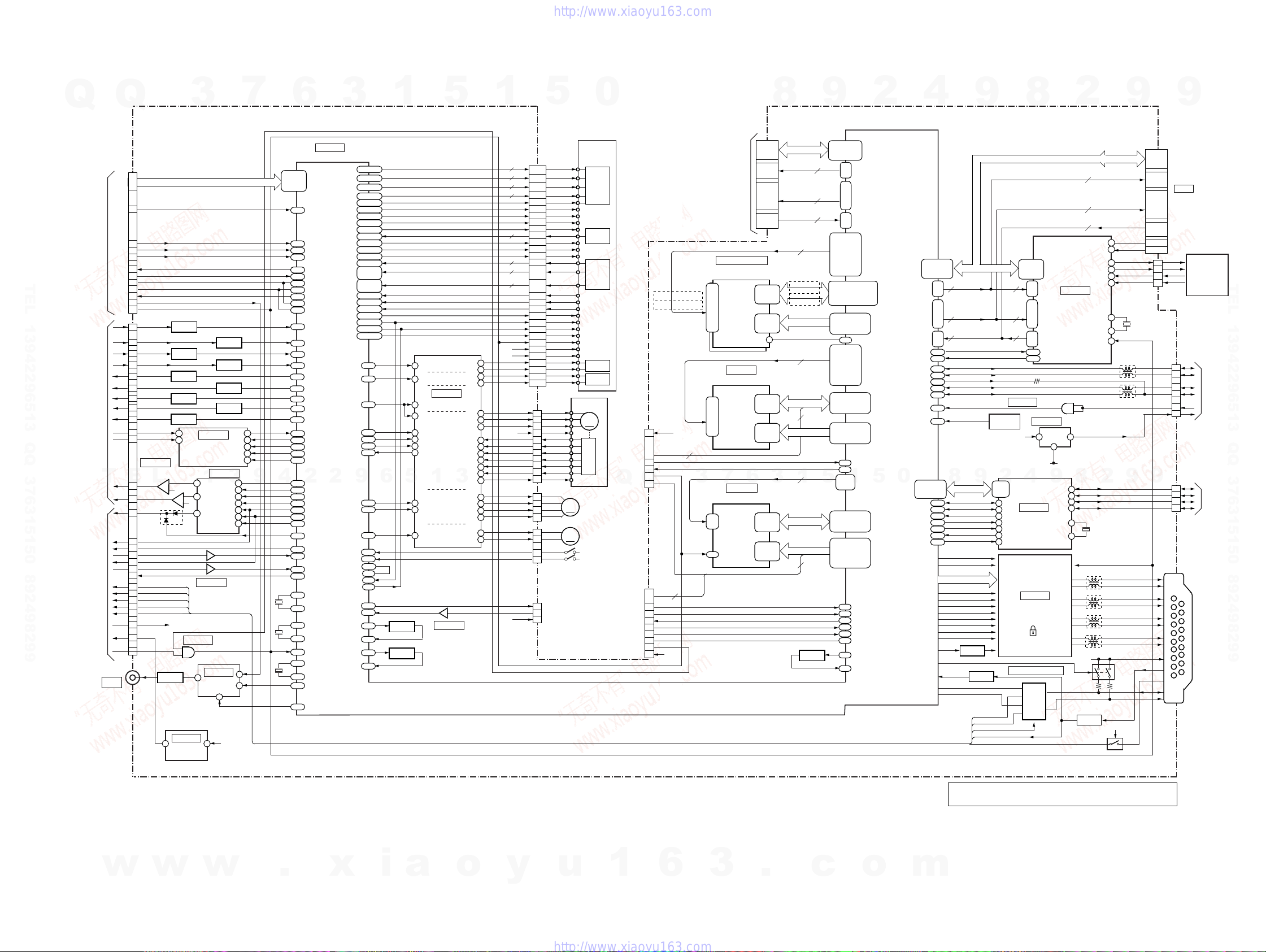
3-4. A V-134 BLOCK DIAGRAM (HX780: AUS, TH, SP, CND, E/HX980: AUS, TH, SP)
Q
Q
3
7
6
3
AV-134 BOARD
DC01
XRST1
AFT
AGC
SDA
SCL
9
SDET1
SDET3
(5/5)
27
26
13
12
8
MSPSTAT
EXCEPT HX780: Canadian, E
TU_VIN
Q604
TU_LIN
BUFFER
Q605
TU_LIN
BUFFER
4
2
2
V1 IN
L_IN
R_IN
V3_IN
L3_IN
R3_IN
9
6
Q601
X601
18.432MHz
Q606
AMP
Q603
AMP
Q602
BUFFER
BUFFER
TU_LIN
IC601
EURO MSP
TU_RIN
DACML
2
AIN1+
XIN
5
DACMR
XOUT
6
22
RESETQ
HX780: Canadian, E
Y1
C1
1
3
Y3
C3
V3
V1
L3
L1
R3
R1
U601
TUNER
UHF/VHF
UHF/VHF
OUT
IN
VIDEO OUT
L OUT
R OUT
SIF OUT
TEL 13942296513 QQ 376315150 892498299
AFT OUT
AGC OUT
SDA
SCL
Y2 IN
21
C2 IN
24
SDET2
23
2VIN
19
L2_LIN
17
L2_RIN
15
CN105(1/2)
E
L
JA403
*
6P RDR-HX780: CND, E model
3P RDR-HX780: AUS, TH, SP/HX980: AUS, TH, SP model
FROM
FR-291 BOARD
(CN202)
(SEE PAGE 3-7)
JA403
*
LINE1/LINE3
S VIDEO
VIDEO
AUDIO L
AUDIO R
T
2L
2R
2Y
2C
SDET2
2V
1
5
18
87
86
7
9
14
92
91
100
1
12
90
89
3
5
16
94
93
BS IN
A TUNER IN(L)
A TUNER IN(R)
SEP Y2 IN
SEP C2 IN
VIDEO L2 IN
A L2 IN(L)
A L2 IN(R)
Y1 IN
C1 IN
VIDEO L3 IN
A L3 IN(L)
A L3 IN(R)
Y3 IN
C3 IN
VIDEO L1 IN
A L1 IN(L)
A L1 IN(R)
5
IC401
VIDEO/AUDIO SELECTOR
F DVD PY (G)
F DVD PR (R)
F DVD PB (B)
DVD VorY OUT
1
3
(3/5)
DVD C OUT
Y2 OUT
C2 OUT
V2 OUT
PY(Y) OUT
Pb(Cb) OUT
Pr(Cr) OUT
F DVD Y
F DVD C
TO DVD (L)
TO DVD (R)
SYNC
SDA
SCL
1
59
36
34
32
40
38
39
51
52
53
55
57
61
80
79
41
42
43
5
Q410
BUFFER
CSYNCIN
AMUTE1
XAMUTE2
0
Q405
BUFFER
3
+
2
_
5
+
6
_
IC402
BUFFER
Q404
MUTE
Q
1
7
(3/5)
Q406
Q407
Q
Y
C
CN101 (1/2)
Q403
BUFFER
2
4
6
8
10
12
14
20
22
26
24
TEXTVIN
JA401
JA402
YP_OUT
CR_OUT
CB_OUT
Y_OUT
C_OUT
Y_IN
C_IN
3
L_OUT
R_OUT
L_IN
R_IN
S VIDEO
VIDEO
AUDIO L
AUDIO R
CB
CR
Y
7
LINE2 OUT
COMPONENT
VIDEO
OUT
6
TO/FROM
RD-066 BOARD
(CN2301)
(SEE PAGE 3-5)
8
3
IC104
DDC SW
14
13
11
10
5
6
9
2
4
9
8
2
9
9
TEL 13942296513 QQ 376315150 892498299
(1/5)
IC101
X101
15MHz
X102
32.768kHz
4312
12
13
512
9
10
15
23
24
33
25
67
71
20
31
81
27
28
69
38
8
IT CONTROLLER
CAPACITOR
CF1
CF2
ACDET
TX1
TX2
MODEL1
SDET3
SDET2
XAMUTE2
SDET1
CSYNCIN
MSPSTAT
AGC
AFT
CVBSIN
SDA
SCL
CEC0
DDC_SW2
RESET
8
RFTHRU
FANCTL
SWVION9V
P_CONT
SWVION5V
TU_DCCON
FLON
FLDATA
FLCLK
FLSTB
KEY1
KEY2
KEY3
P_CONT2
MRST
XRST
DAM_TO_T
HSM_TO_T
DAT_TO_M
ASCK
HST_TO_M
DDC_SW1
HOTPLUG
TUON
9
IR
RFTHRU
52
FANCTL
54
TUON
60
SWVION9V
61
P_CONT
62
SWVION5V
64
TU_DCCON
74
(SEE
"POWER BLOCK
DIAGRAM")
63
49
51
50
17
18
19
7
57
65
29
99
6
98
100
79
37
73
2
FLPON
FLDATA
FLCLK
FLSTB
KEY1
KEY2
KEY3
IR
CN101 (2/2)
4
CN105(2/2)
9
9
2
8
9
13
9
7
5
TO/FROM
FR-291 BOARD
(CN202)
2
3
6
4
P_CONT2
28
MRST
29
XRST1
30
DAM_TO_T
31
HSM_TO_T
32
DAT_TO_M
33
ASCK
34
HST_TO_M
35
DDC_SW1
39
HPD
40
DSDA
36
DSCL
38
CEC
37
AMUTE1
23
(SEE PAGE 3-7)
TO/FROM
RD-066 BOARD
(CN2301)
(SEE PAGE 3-5)
(1/5)
IC103
IC101 VDD DET
IC101 VDD
IN
OUT
(1/5)
IC102
POWER FAIL DET
V+5V
IN
OUT
V+5V
0
5
1
5
1
SDET3
SDET2
XAMUTE2
SDET1
CSYNCIN
MSPSTAT
AGC
AFT
(1/5)
SDA0
12
SCL0
9
7
1
V+5R8E
Q101
RESET
w
w
w
.
x
i
a
o
y
u
1
6
3
.
c
o
3-7 3-8
• Abbreviation
AUS : Australian model
CND : Canadian model
SP : Singapore model
TH : Thailand model
m
3-5. RD-066 BLOCK DIAGRAM
Q
Q
3
RD-066 BOARD
7
6
3
1
5
1
5
0
8
9
2
4
RDR-HX680/HX780/HX785/HX980/HX1080
9
8
2
9
9
(2/7,4/7 to 7/7 )
EXCEPT CS
CN4701
8
STREAM0-7
|
15
VCLKI
17
(not use)
TEL 13942296513 QQ 376315150 892498299
TO/FROM
AV-133/AV-134
BOARD
(CN101(1/2))
(SEE PAGE 3-4)
T
TO/FROM
AV-133/AV-134
BOARD
(CN101(2/2))
(SEE PAGE 3-4)
DIGITAL
JA5701
OUT
5
4
6
23
22
26
25
28
2
20
29
27
25
23
39
37
33
31
35
15
17
E
21
19
18
10
9
8
7
6
40
5
3
2
1
4
13
12
11
ADATA
ABCKI
ALRCKI
TXI
RXI
SDA_VDEC
SCL_VDEC
AT/XDT
SPDIF_LL
XRESET
CN2301
Q3301, 3302
YIN
YP_OUT
Y_OUT
Y_OUT
LCHIN
RCHIN
IC3202
L_OUT
R_OUT
AMUTE1
DAM_TO_T
HSM_TO_T
DAT_TO_M
ASCK
HST_TO_M
X525P
DSDA
DSCL
DDC_SW1
HDP
CEC
P_CONT2
MRST
XRST1
Y EQ
C/R_IN
Q3305, 3306
G_IN
G EQ
B_IN
Q2503
BUFFER
CR_OUT
Q2501
BUFFER
C_OUT
Q2504
BUFFER
2
1
(3/7)
AUDIO LPF
2
L
_
+
3
1
_
+
7
D3201
TU_DSDA
TU_DSCL
DDC_SW1
TU_HPD
TU_CEC
1
2
Q5701
BUFFER
IC3707
12
RESET
(3/7)
AINL
AINR
AUDIO DAC
7
6
8
5
11
IC3702
8
IC3101
AUDIO ADC
(3/7)
IC3201
1
VOUTL
VOUTR
ZEROR
17
35
IC3701
4
IC5701
SPDIF SELECT
(3/7)
Q3303, 3304
C/R EQ
Q3307, 3308
B EQ
Q2505
BUFFER
Q2502
BUFFER
3
DATA
BCKIN
LRCKIN
MCLK
MD
MC
ML
SMDOUT
HSMTOT
SMDIN
SMCKOUT
HSTTOM
X525P
(3/7)
1
V+1R5_IN
SDTO
LRCK
MCLK
SCLK
PON
(3/7)
9
10
11
12
13
(3/7)
2
1
3
16
13
14
15
5
13
9
AIBD0
AILRCK0
ADCCLKO
AIBCK0
ADPOW
AOD0
4
AOBCK
AOLRCK
DACCLKO
SMDOUT
SMCKOUT
NSCS
AMUTE
X101
16.9344MHz
X1001
24.576MHz
XRESET
X1002
27MHz
SPDIFO
SPDIFSEL
AF24,AE24,
AE21,AD24,
AF23,AD23,
AC24,AC22
IC1001
AV ENC/DEC
PKPULSEP1P,
AH2, AH1
PKPULSEP1M
VIOD0
PKPULSEP2P,
AJ4, AJ3
PKPULSEP2M
|
VIOD7
WRPULSEP,
AH4, AH3
WRPULSEM
FPDVI, PDIN
A1,B1,C1,D1
G1,H1,F1,E1
2
RFP, RFN
GPI046
GPI044
VREFIO
PLED
P2LD
WLD
RFP3
SDRV1
SDRV2
DAOUT
GPI045
TXD1B
RXD1B
PB4
RLD
PA3
PB3
PB5
PB0
PB1
PA2
TDRV
FDRV
REF16
MDRV
FSCO
HLCO
RFP1
RFP2
PA7
PA6
SFSO
SFSCK
FSCI
HLCI
SFSI
AG9, AG8
AH12, AJ12
AJ11,AJ10,
AH9,AH8,
AH10,AH11
FG
9
AH5, AJ5
AE6
AE11
AF11
AE9
AF8
AG6
AG1
AF6
AJ9,AJ8
AG4
AE7
AJ23
AH7
AI8
BI8
AF10
AH20
AH21
AF9
AJ22
AG21
AH22
AG20
AJ21
AJ20
AJ19
AH6
AJ7
E17
AD8
AD10
AD9
AG23
AG22
K23
J24
K20
H21
XDMUTE1
XDMUTE2
6
SL1
SL2
LD
SO
SI
SCLK
Q1811
FSC BPF
Q1801
HCL BPF
HFONP,HFONM
VIOCLK
AB20
AIOBD
AB22
AIOBCK
AA20
AIOLRCK
AE20
TXD0B
AF21
RXD0B
AF22
SDA0
L19
SCL0
M19
GPIO6
T19
SDA1
C18
SCL1
D17
AYI
E24
ACI
G24
ABI
D23
ARI
F23
VAG
B23
VAR
A22
A20
VAY
B21
VAC
A24
VAB
VAC
AIBD0
E20
AILRCK0
F19
AIOMCK0
C20
AIBCK0
E19
GPIO37
U19
2
AOD0
E18
AOBCK
C19
AOLRCK
D20
AIOMCK1
E21
SMDOUT
L4
SMCKOUT
K5
GPIO62
L3
GPIO54
F17
GPIO04
P19
SMDIN
L5
GPIO03
N19
GPIO41
AB19
XA1
AE1
XA2
AF1
CLK24IN
M24
CLK24OUT
L24
RSTSWB
L21
CLK27AIN
L1
CLK27AOUT
K2
ATX
D19
GPIO36
V19
5
4
5
42
47
26
34
35
43
29
30
46
W2EN+. W2ENW3EN+, W3ENW1EN+, W1ENOSCEN+, OSCEN-
LDDEN
W3SET
W2SET
W1SET
APCV
FMO+, FMODVD/CD
HFGAIN
OSCNT
RF+, RFA, B, C, D
ACTIN1
ACTIN2
VC
ACTIN3
SPIN
CTL1
CTL2
FG
SL1IN
SL2IN
LDIN
S1-S4
TRACKING
COIL DRIVE
FOCUS
COIL DRIVE
IC501
(7/7)
SPINDLE
MOTOR
1
MOTOR
LOADING
MOTOR
26
IC3701
(3/7)
DRIVE
DRIVE
DRIVE
(not use)
DQ0
|
DQ15
A0
|
A12
IC201
64Mbit SDRAM
DQ0
|
DQ15
A0
|
A11
6
IC1102
128Mbit FLASH ROM
DQ0
|
DQ15
A0
|
A21
24,26,28,30,
32,34,36,38,
37,35,33,31,
29,27,25,23
6,
8,
20
18
16
40
14
12
10
2,4,5,7,8,10,
11,13,54,56,
57,59,60,62,
63,65
29-32,
35-40,
28,41,42
VREF
(4/7)
2,4,5,7,8,10,
11,13,42,44,
45,47,48,50,
51,53
23-26,
29-34,
22,35
(4/7)
35,37,39,41,
44,46,48,50,
36,38,40,42,
45,47,49,51
31,26-20,
10-3,54,19,
18,11,12,
15,2
5
4
3
(4/7)
49
3
CN3801
HADRS5-7,13
AT0DATA0-15
AT0ADR0-2
AT0CS0
AT0CS1
AT0DMARQ
AT0DIOW
AT0DIOR
AT0RESET
AT0IORDY
AT0DMACK
AT0INTRQ
DDATA0-7,16-23
DDATA8-15,24-31
MD2
MD5
MD1
MD0
HDATA0-15
HADRS1-23
DVD
OPTICAL
PICK-UP
24, 23
2
22, 21
2
20, 19
2
18, 17
2
16
15
14
13
12
34, 33
2
31
30
27
44, 42
2
4
4
SW1
SW2
TEMP
LCDS
SI
SCLK
VRPD
XRESET
V+5L
V+3A
ACO1+
54
ACO1-
53
ACO2+
52
ACO2-
51
U
11
V
13
W
16
HU+
20
HU-
21
HV+
22
HV-
23
HW+
24
HW-
25
HB
19
3
SLO1+
SLO1-
SLO2+
SLO2-
40
39
38
37
LDO+
2
LDO-
1
SLED
T+
TF+
F-
V+5M
ST1+
ST1ST2+
ST2-
LDO+
LDO-
CLOSE
OPEN
TXD
RXD
V+5D
39, 38,
37, 40
48, 47,
46, 49
35, 45
50
36
11
41
10
12
11
10
7
6
5
9
3
4
1
2
4
3
2
9
8
7
6
5
1
2
4
3
1
2
4
5
1
2
5
CN101
CN501
CN502
RED
BLACK
LPS1
LPS2
CN601
FOR CHECK
U
V
W
VCC
HU+
HUHV+
HVHW+
HWHB
M3,M4,M1,M2
SEN
SDIO
SCLK
VREFPD
RESET
VA5V
VD3V
TR
TD
FR
FD
CN1402
BLOCK
LD
DRIVER
RSET
LASER
FRONT
MONITOR
DBA0, DBA1
DCLKO, DCLKNO
(IC1201)
(IC1221)
DWE
DCAS
DRAS
DCS0B
DCKE
DDM0, DDM2
DDQS0, DDQS2
DDM1, DDM3
DDQS1, DDQS3
SPINDLE
MOTOR
PHOTO
DETECTOR
TRACKING
COIL
FOCUS
COIL
M
V+3D
10
PW
1
D5(AG)
3
D1(SL)
4
D0(MA)
5
H
SLED
M
MOTOR
LOADING
M
MOTOR
CLOSE
OPEN
FOR CHECK
Q
CN1401
FOR CHECK
CN201
Q
13
12
6
10
8
14
2
4
1
TX_FE
8
RX_FE
9
XRESET
7
A9(ATA)
2
HADRS13
HADRS5
JTSEL
HADRS6
DINTEN
3
9
EJSNGEN
TDI
TCK
TDO
TMS
TRST
DINT
RST
HADRS7
3
V+3D
LDQM
UDQM
MBA
WEZ
CASZ
RASZ
MCLK
MCKE
4
HCS0
HDOE
HWS0
XRESET
JTDI
JTCL
JTDO
JTMS
JTMRST
EDINT
3
IC1201,1221
512Mbit X 2 DDR SDRAM
26, 27
BA0, BA1
45, 46
CK, /CK
21
/WE
22
/CAS
23
/RAS
24
CS
44
CKE
20, 47
LDM, HDM
16, 51
LDQS, UDQS
15
LDQM
39
UDQM
20
BA0
16
/WE
17
/CAS
18
/RAS
38
CLK
37
CKE
7
32
CE
34
OE
13
WE
14
RESET
17
(IC1201)
(IC1221)
DADRS0-12
VREFD
8
MD0-15
4
MA0-11
1
3
4
Q102
SW
V14,U11,U12,W15,
V11,T12,P13,R15,
R13,V10,P15,U13,
R14,U15,W13,T14
3
6
3
F5,F4,G5,G4,J4,J5,H4,H5,
A8,B8,C8,A7,B6,A6,C7,B7,
G1,G2,G3,F1,H3,H2,H1,J3,
D9,E9,D8,E8,D7,E7,D6,E6
D3,E4,C4,D4,E5
Y3,AA4,AB1,AA5,
AB3,AA3,W4,Y4,
W5,W3,Y5,Y2,
AC2,AB5,AA1,Y1
AE3,AD3,AF3,AE5,
AE4,AD2,AD1,AC5,
REMO
REMI
5
W21,Y21,AA21,U23,
V22,T24,U24,N23,R23,
M22,T22,T21,P21,N22,
Y20,Y24,AA22,W23,
V23,Y23,V21,AA23,
Y22,P22,U22,P23,U21,
U20,AB24,R24,M21,
N21,T23,R22,M20,W20,
W14
U10
U14
W12
W11
T15
P14
R12
V13
T13
V15
V12
B3, A3,
C1, B1,
C2, B2,
A2, C3,
D5,
F3, J1,
F2, J2,
A5, B9,
C6, C9
B4,A4,C5,B5,
E1,E2,D1,D2,
F6
AA2
AB2
AD5
AF2
AE2
AF4
AB4
AC4
AD4,AC1,AC3
AF7
AG5
V24
1
W22
AA24
N20,R21
P24
F21
J19
G19
G20
H20
H19
AJ2
AJ14
AT0DA0
|
AT0DA2
AT0CS0B
AT0CS1B
AT0DMARQ
AT0DIOWB
AT0DIORB
AT0RESETB
AT0IORDY
AT0DMACKB
AT0INTRQ
DVREF
PB7
PB6
FCSB0
FOEB
FWEB
JTDI
JTCL
JTDO
JTMS
JTRST
EDINT
OFPULSE
FCEFM1
AT0D00
|
AT0D015
DBA0, DBA1,
DCLKO, DCLKNO,
DWEB, DCASB,
DRASB, DCS0B,
DCKE,
DDQM0, DDQM2,
DDQS0, DDQS2,
DDQM1, DDQM3,
DDQS1, DDQS3
DQ00
DQ31
DADD00
|
DADD12
LDQM
UDQM
MBA
WEB
CASB
RASB
MCLKOUT
MCKE
MD0
|
MD15
MA0
|
MA11
5
RDATA00
|
RDATA015
RADD01
|
RADD23
|
AT1D00
|
AT1D015
AT1DMARQ
AT1DIOWB
AT1DIORB
AT1RESETB
AT1IORDY
AT1DMACKB
AT1INTRQ
USB_D_CONEECT
USB_D_DN0
USB_D_DP0
USB_D_VBUS
0
PHY_D0
|
PHY_D7
AT1DA0
AT1DA2
AT1CS0B
AT1CS1B
TXD2B
RXD2B
USB_DN0
USB_DP0
USB_CLKI
E13,D13,E12,
D12,E11,D11,
LINKON
GPIO52
M4,R1,R4,R2,
N5,R3,P4,T1,
T2,P5,T3,R5,
U1,N4,U2,W1
|
E10,D10
CTL0
CTL1
SCLK
LREQ
LPS
17,15,13,11,
X5502
25MHz
PDIAG#
DASP#
XRESET
L5201
L5202
9
CN5604
12,14,16,18
+5V
9,7,5,3,
4,6,8,10,
35,
33,
36
37
38
21
23
25
27
29
31
34
39
USBDM2
USBDP2
USBDM1
USBDP1
USBVFB
V+5USB
9
CN3802
IDE HDD
1
2
3
5
6
TPAP
TPAN
TPBP
TPBN
HDD
UNIT
TEL 13942296513 QQ 376315150 892498299
10
8
TO/FROM
FL-184 BOARD
3
(CN102)
1
(SEE PAGE 3-7)
5
6
CN5201
1
TO/FROM
2
FL-184 BOARD
(CN101)
5
(SEE PAGE 3-7)
6
CN5101
JA5801
DD0-15AT1DATA0-15
XRESET
DET
3
6
3
PDIAGn
24.576MHz
L5001
L5002
L5003
L5004
DASPn
TXP
TXN
RXN
RXP
XTALI
XTALO
PORn
2
X5101
Q5802,5804
Q5808
34
46
32
31
28
27
22
23
17
V+3HD
DA0-2
CS0#
CS1#
DMRQ
DIOW#
DIOR#
RESET#
IORDY
DMACK#
INTRQ
AT1ADR0-2
AT1CS0
AT1CS1
AT1DMARQ
AT1DIOW
AT1DIOR
AT1RESET
AT1IORDY
AT1DMACK
AT1INTRQ
62,64,2,5
DD0
X5201
48MHz
XTAL OSC
2
8,9,11,
12,14,15,
17,18
5
6
2
63
59
58
55
IC5203
EV+5.8V
D0
|
D7
CTL0
CTL1
SCLK
LREQ
LPS
LKON
RESETB
7,11,13,15
14,12,10,6
3,1,63,61
3
6
3
4
IC5103
50
51
49
48
47
60
59
58
16
55
54
53
43
45
DV PHY
(6/7)
DA0
|
DA2
CS0n
CS1n
DMARQ
DIOWn
DIORn
RESETn
IORDY
DMACKn
INTRQ
UAI
UAO
(6/7)
IC5204
DD15
|
5V
REG
2
V+3D
9
4
TPA0p
TPA0n
TPB0p
TPB0n
X0
X1
IC5602
SATA BRIDGE
(5/7)
1
2
(6/7)
31
8
39
38
37
36
22
23
AT1DATA0-15
U3
AT1ADR0-2
W2
3
T5
AT1CS0
AT1CS1
T4
AT1DMARQ
V3
AT1DIOW
V5
AT1DIOR
U5
AT1RESET
V1
6
AT1IORDY
V4
AT1DMACK
U4
AT1INTRQ
V2
3
M5
TXD2_BRIDGE
AJ24
RXD2_BRIDGE
AH23
USB_DN0
M1
USB_DP0
M2
USB_D_CONEECT
P3
USB_D_DN0
P1
USB_D_DP0
P2
USB_D_VBUS
N3
USB_CLKI
N1
9
8
PHY_D0-7
PHYCTL0
E14
PHYCTL1
D14
PHYSCLK
D15
PHYLREQ
E15
PHYLPS
D16
PHYLINKON
E16
PHY_XRST
F20
IC5801
Q5809,5811
SW
Q5810
LEVEL
SHIFT
TU_DSDA
TU_DSCL
DDC_SW1
TU_HPD
TU_CEC
IC5803,5804
V+5VHD
(6/7)
Q5801,5805
w
w
w
.
x
i
a
o
y
u
1
6
3
.
c
o
m
3-9 3-10
Note: The HDMI block is highly confidential, and prohibited from releasing to public.
The components identified by mark 9 contain confidential information.
Strictly follow the instructions whenever the components are repaired and/or replaced.
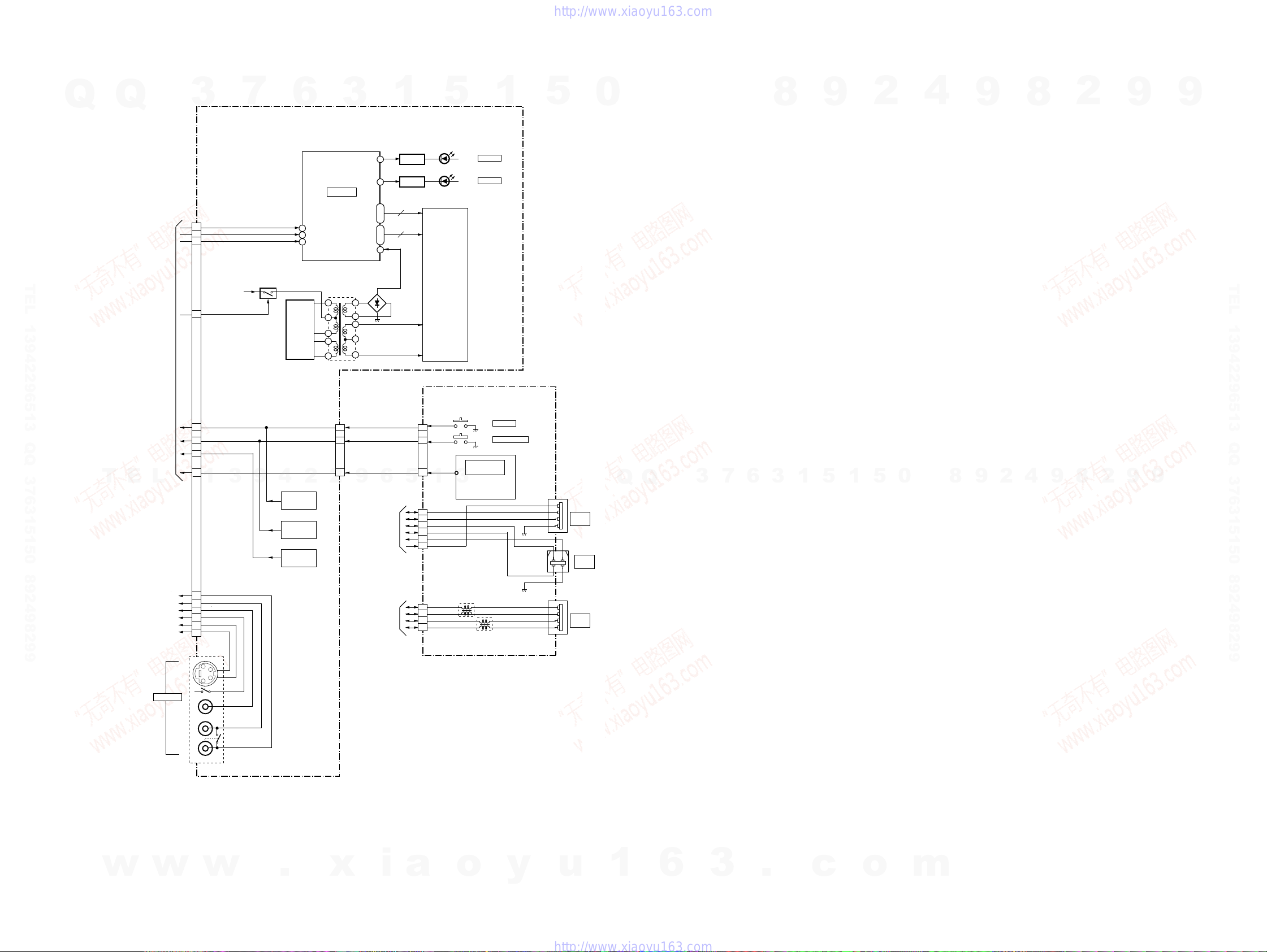
RDR-HX680/HX780/HX785/HX980/HX1080
3-6. FR-291, FL-184, VDC-001 BLOCK DIAGRAM
Q
Q
3
7
6
FR-291 BOARD
3
1
5
1
5
0
8
9
2
4
9
8
2
9
9
LED2
2
LED3
SG1
SG16
GR1
GR12
VEE
10
1
7
8
9
9
TO/FROM
RD-066 BOARD
(CN5201)
(SEE PAGE 3-6)
3
14
|
|
29
42
|
|
31
30
D208-211
6
IC201
FL DRIVER
FLDATA
16
FLCLK
18
FLSTB
20
TEL 13942296513 QQ 376315150 892498299
FLPON
12
TO/FROM
AV-133/AV-134
BOARD
(CN105)
(SEE PAGE 3-4)
KEY3
19
KEY1
23
KEY2
22
IR
T
E
L
21
1
V+12RIE
3
Q203,204
9
CONVERTER
4
S209,210,208
OPEN/CLOSE,
S201-203
REC STOP,
INPUT SELECT,
Q201,202
DC/AC
HDD,
DVD
REC
S204-207
CH+, CH-,
PLAY,
STOP
7
8
9
CLK
STB
2
DIN
T201
DC/AC CONVERTER
TRASFORMER
2
3
4
5
6
5
4
3
CN201
2
Q206
LED DRIVE
Q205
LED DRIVE
SEG1
SEG16
16
GRD1
GRD12
12
5
|
|
ND201
FLUORESCENT
DISPLAY
F2
F1
FL-184 BOARD
KEY3
1
KEY1
2
IR
3
CN106
1
3
USBDM2
7
USBDP2
9
USBDM1
3
USBDP1
1
USBVFB
6
V+5USB
5
CN102
D214
DVD
D212
HDD
S101
S102
IC101
REMOTE CONTROL
RECEIVER
POWER
ONE TOCH DUB
2 1
3 4
TEL 13942296513 QQ 376315150 892498299
9
9
2
8
9
4
2
9
Q
Q
1
CN104
2
3
USB
A TYPE
4
CN105
USB
B TYPE
3
0
5
1
5
1
3
6
7
8
w
S VIDEO
LINE2 IN
VIDEO
AUDIO L
(MONO)
AUDIO R
w
J201
2R
10
2L
8
2V
6
SDET2
2
2C
1
2Y
4
CN202
w
TO/FROM
RD-066 BOARD
(CN5101)
(SEE PAGE 3-6)
3
4
5
7
9
11
.
x
i
2
1
5
6
a
CN101
TPAN
TPBP
TPBN
o
FL101
y
FL102
TPAP
4
TPA+
TPATPB+
TPB-
3
2
1
u
CN103
DV
IN
1
6
3
.
c
o
m
3-11 3-12
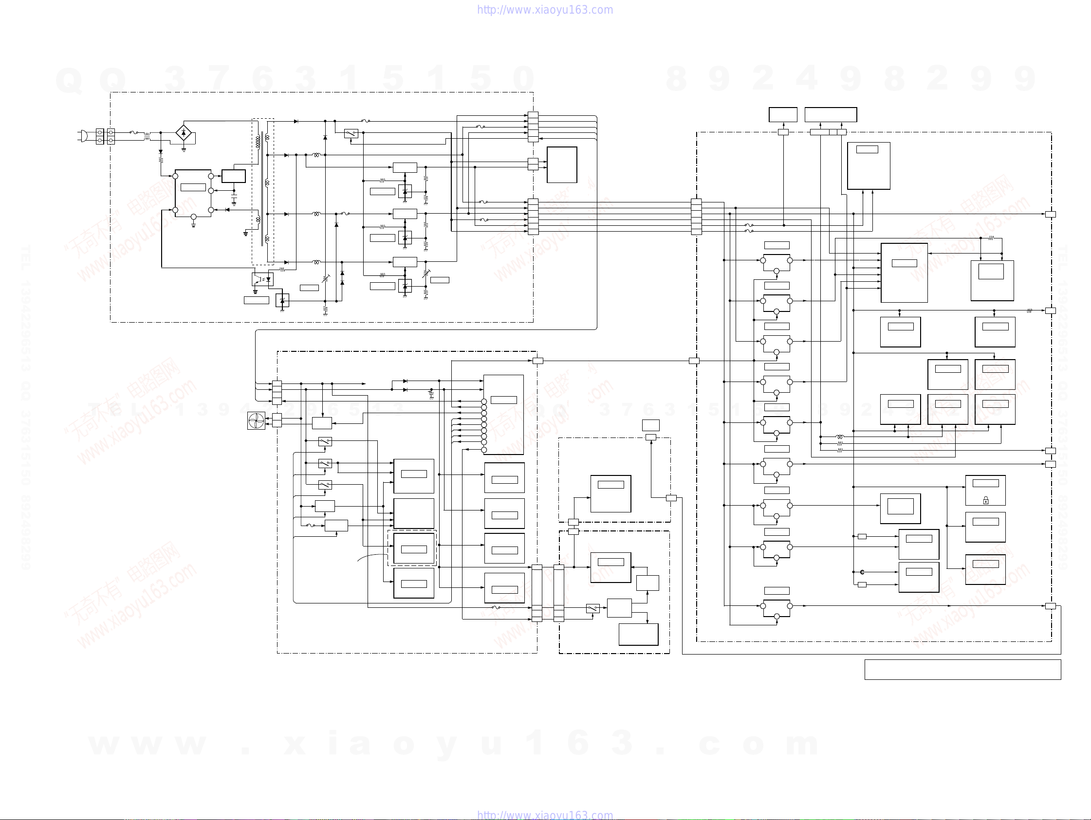
3-7. POWER BLOCK DIAGRAM
Q
AC IN
Q
3
SWITCHING REGULATOR
CN101
L
N
FU101
T3.15A/250V
L101,102
LPF
D101-104
D109
2
IC101
SWITCHING
REGULATOR
4
7
58
3
6
Q101
SWITCHING
D105
6
T101
SWITCHING
TRANSFORMER
3
D401
D201
D501
1
D402
L201
P501
L501
D502
TEL 13942296513 QQ 376315150 892498299
T
E
L
1
3
9
PC101
PHOTO
COUPLER
4
IC201
SHUNT REG
FAN
CN302
(AV-114)
2
D601
CN301
2
4
1
1
2
CN201
L601
VR201
5.8V ADJ
AV-133/134 BOARD
EV+12.1V
P-CONT
2
FAN+
FAN-
9
RFTHRU
SWVION5V
TUON
SWVION9V
IC317
Q201
FAN DRIVE
Q301,302
Q305,306
Q303,304
Q307,308
9V REG
TU_DDCON
6
Q309-311
DC/DC CONV.
V+12R1
V+5R8E
V+12R1E
V+5BB
V+5TU
V+9V
Q401,402
D603
D604
5
FANCTL
V+5VD
V+5VI
V+32V
EXCEPT
HX780 : CND,E
RDR-HX680/HX780/HX785/HX980/HX1080
5
P401
EV+12V
SW+12V
EV+5.8V
IC202
SHUNT REG
3.3V REG
IC501
SHUNT REG
IC601
SHUNT REG
1
3
Q201
5V REG
Q501
Q601
1.5V REG
D103
D104
C118
BACK-UP
(3/5)
IC401
VIDEO/AUDIO
SELECTOR
U601
TUNER
(5/5)
IC601
EURO MSP
(3/5)
IC402
BUFFER
1
SW+5V
SW+3.3V
SW+1.5V
VR601
1.5V ADJ
V+5V
5
P_CONT
P_CONT2
FANCTL
RFTHRU
TUON
SWVION9V
SWVION5V
TU_DCCON
FLPON
P201
P204
62
57
54
52
60
61
64
74
63
SW+1.5V(T)
EV+12V(T)
EV+5.8V(T)
SW+3.3V(T)
P_ON/OFF
EV+5.8V(M)
SW+1.5V(M)
SW+3.3V(M)
SW+12V
P402
SW+5V(W)
SW+12V(W)
(1/5)
IC101
IT CONTROLLER
(1/5)
IC102
POWER FAIL DET
(1/5)
IC103
IC101 VDD DET
(1/5)
IC104
DDC SW
(4/5)
IC406
AVLTH SW
IC150
0
11,12
9
6,7
2,4
1
CN202
SW+12V(H)
1
SW+5V(H)
4
CN203
1
3,4
6,7
9
11
13
CN201
CN101
Q
CN105 CN202
9
IC5602
(5/7)
SATA BRIDGE
IC5103
(6/7)
2
IC3701
IC3202
8
DV PHY
9
IC1201
IC1221
(4/7)
512Mbit X 2
DDR SDRAM
IC1102
128Mbit FLASH ROM
9
IC5801
IC5701
SPDIF SELECT
IC5203
IC3702
IC3101
(6/7)
(3/7)
(6/7)
AND GATE
AND GATE
9
AUDIO ADC
(3/7) (3/7)
BUFFER
2
AUDIO LPF
9
R223
V+5USB
CN1401
1
FOR CHECK
TEL 13942296513 QQ 376315150 892498299
CN201
10
FOR CHECK
CN1402
5
FOR CHECK
JA5801
18
6
CN5201
SPINDLE
MOTOR
CN501
IC4511
3V REG
VIN VOUT
ON/OFF
1
IC4521
2.5V REG
VIN VOUT
ON/OFF
1
IC4531
1V REG
VIN VOUT
CONT
5
IC4541
3V REG
VIN VO
CONT
5
IC4552
5V REG
0
VIN VOUT
ON/OFF
1
IC4561
5V REG
VIN VOUT
CONT
1
IC4562
3V REG
VIN VOUT
CONT
1
IC4571
1.8V REG
VIN VOUT
ON/OFF
4
IC5204
5V REG
VIN VOUT
VC
2
12
4
(1/7)
54
(1/7)
V+2R5
54
(1/7)
V+1R0
18
(1/7)
V+3A
17
(1/7)
V+5L
54
(1/7)
V+5HD
45
(1/7)
V+3HD
45
(1/7)
V+1R8
15
(6/7)
5V
31
DVD
OPTICAL PICK-UP BLOCK
VA5V VD3V
25,26,35,45
CN101
8
9
10
9
L4551
TRACKING COIL DRIVE
SPINDLE MOTOR DRIVE
SLED MOTOR DRIVE
LOADING MOTOR DRIVE
8
IC501
(7/7)
FOCUS COIL DRIVE
V+2R5
V+1R5_IN VREF_D
L5601
EMI
L5101
L5122
EMI
V+3V
V+3D
V+2R5
V+1R0
V+3A
V+3D
V+3D
2
V+3D
V+5AO
V+5A IN
V+5D
V+12VA
V+3D
IC1001
AV ENC/DEC
(2/7, 4/7 to 7/7)
IC201
(4/7) (4/7)
64Mbit SDRAM
IC3201
4
(3/7) (3/7) (3/7)
AUDIO DAC
IC5803
IC5804
(6/7)
V+3DS
V+3V_A
V+3V_D
1
EV5.8V
V+3D
V+1R5_IN
EV5.8V
EV5.8V
IC4502
IC4501
2
V+12A
P_CONT2
P_CONT2
P_CONT2
P_CONT2
5
P_CONT2
8
HDD
UNIT
EV+5.8V
SW+1.53V
SW+3.33V
V+12V
V+5M
V12M
28
3
6
7
Q
3
CN104
USB
ATYPE
1
9
RD-066 BOARD
EV+5.8V
1
V+1R5_IN
3,4
V+3D
6,7
V+12V
9
V+5M
11
V12M
13
CN4501
P_CONT2
13
CN2301
5
1
FL-184
BOARD
IC101
REMOTE
COMMANDER
V+5F
RECEIVER
CN106
5
1
CN201
FR-291 BOARD
IC201
1
15
13
V+5F
24
V+12RIE
14
FLPON
12
Q203,204
FL DRIVE
Q201,202
CONVERTER
T201
DC/AC
VEE
D208-211
F1,F2
ND201
FLUORESCENT
DISPLAY
V+5USB
5
CN102
RECT
EV5.8V
EV5.8V
V+3D
EV5.8V
V+3D
w
w
w
.
x
i
a
o
y
u
1
6
3
.
c
o
m
3-13 3-14E
Note: The HDMI block is highly confidential, and prohibited from releasing to public.
The components identified by mark 9 contain confidential information.
Strictly follow the instructions whenever the components are repaired and/or replaced.
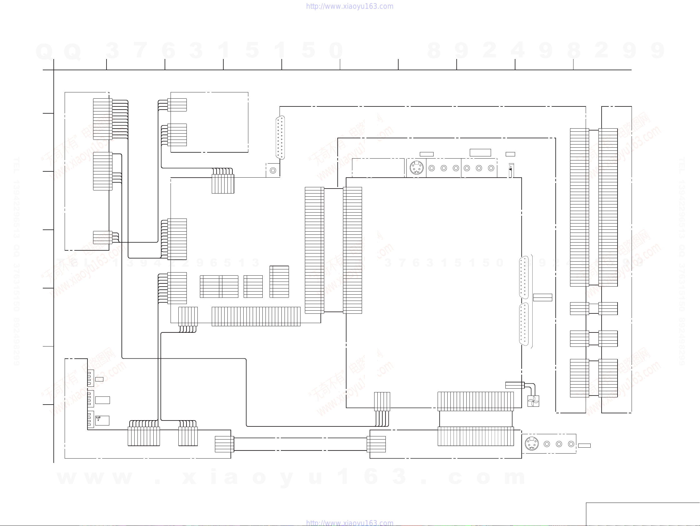
SCHEMA TIC DIAGRAMS AND PRINTED WIRING BOARDS
4-1. FRAME SCHEMATIC DIAGRAM
Q
Q
3
1
7
2
SECTION 4
6
RDR-HX680/HX780/HX785/HX980/HX1080
3
1
3 4 5 6 7 8 9 10
5
1
5
0
8
9
2
4
9
8
2
9
9
A
B
TEL 13942296513 QQ 376315150 892498299
POWER
BLOCK
SWITCHING
( )
REGULATOR
CN201 13P
CN202 12P
EV+5.8V(M )
SW+1.5V(M )
SW+1.5V(M )
SW+3.3V(M )
SW+3.3V(M )
SW+12V
SW+5V(W )
GND(W)
SW+12V(W)
P_ON/OF F
SW+3.3V(T )
SW+3.3V(T )
EV+5.8V(T )
EV+5.8V(T )
EV+12V
SW+1.5V(T )
SW+1.5V(T )
4P
1
GND
2
3
4
5
GND D
6
7
GND
8
9
GND(J)
10
11
12
13
1
2
GND
3
4
GND
5
6
7
GND
8
9
GND
10
11
12
PH-080
HARNESS
5V
4
GND
3
GND
2
12V
1
7P
1
GND
2
HT+
3
HT-
4
GND
5
HA-
6
HA+
7
GND
RH-059
HARNESS
HDD UNIT
1234567
TXP
GND
CN5604 7P
TXN
C
CN4501 13P
EV+5.8 V
1
GND D
2
SW+1.53V
4
3
4
5
6
7
8
9
10
11
12
13
2
10
9
8
7
6
5
4
3
2
1
GND D
GND D
GND
V+5M
GND M
V12M
SW+1.53V
SW+3.33V
SW+3.33V
V+12V
CN5201 10P
USBDM2
GND
USBDP2
GND
V+5USB
USBVFB
GND
USBDM1
GND
USBDP1
TPBN
6
2
TPBP
A_GND
CN5101 6P
TPAN
A_GND
9
TPAP
12345
CN1401 14P
1
V+3
2
DINT
3
JTSEL
4
RST
5
GND
6
TCK
7
GND
6
8
9
10
11
12
13
14
SDA_VDEC
GND
AT/XDT
CN203 4P
SW+5V(H)
4
GND
3
GND
2
SW+12.1V(H)
1
PR-078
T
E
D
L
1
3
HARNESS
9
E
RXP
RXN
GND
GND
RD-066 BOARD
5
1
TM9
DINTEN
TDO
GND
TIX
EJSNGEN
TRSET
SCL_VDEC
GND
CN1402 7P
1
2
3
4
5
6
7
GND
GND(RFE/XLL)
XRESET
RX1
TX1
GND
3
TXD
RXD
DTR
CTS
V+5D
GND D
XRESET
CN4701 28P
GND
VCLKI
(not use)
JA5701
STREAM_7
STREAM_6
STREAM_5
STREAM_4
JA5801
STREAM_3
11112
CN201 10P
1
PW
2
A9(ATA)
3
D5(AG)
4
D1(SL)
5
D0(MA)
6
GND
7
XRESET
8
TXFE
9
RXFE
10
V+3D
STREAM_0
STREAM_1
STREAM_2
10111213141516171819202122232425262728
DVD-UNIT
CN101 50P 50P
SCLK
COMPONENT
23
VIDEO OUT
TUNER
CN2301 40P CN101 40P
40
X525P
39
YP_OUT
38
GND
FRA-006
37
CR_OUT
FLEXIBLE
36
GND
FLAT CABLE
35
CB_OUT
34
GND
33
Y_OUT
32
GND
31
C_OUT
30
GND
29
Y_IN
28
GND
27
C/R_IN
26
GND
25
G_IN
24
GND
23
B_IN
22
GND
21
L_OUT
20
GNDA
19
R_OUT
18
AMUTE
17
R_IN
16
GND
15
L_IN
14
GND
13
P_CONT2
12
MRST
11
XRST1
10
DAM_TO_T
9
HSM_TO_T
8
DAT_TO_M
7
ASCK
6
HST_TO_M
5
DSDA
4
CEC
3
DSCL
2
DDC_SW 1
1
HDP
GND
SPDIF
GND
ABCKI
ADATA
ALRCKI
GND
123456789
40
39
38
37
36
35
34
33
32
31
30
29
28
27
26
25
24
23
22
21
20
19
18
17
16
Q
15
14
13
12
11
10
9
8
7
6
5
4
3
2
1
HPD
DDC_SW 1
DSCL
CEC
DSDA
HST_TO_M
ASCK
DAT_TO_M
HSM_TO_T
DAM_TO_T
XRST1
MRST
P_CONT2
GND
L_IN
GND
R_IN
AMUTE1
R_OUT
GNDA
L_OUT
GND
B_IN
GND
G_IN
GND
C/R_IN
GND
Y_IN
GND
C_OUT
GND
Y_OUT
GND
CB_OUT
GND
CR_OUT
GND
YP_OUT
X525P
Q
3
7
3
6
AV-133/134 BOARD
1
5
1
5
0
G-LINKLINE 2 OUT
12
2
9
8
JA501
LINE1 / DECODER
20 21
41 42
LINE3-TV
2223
RESET
VD3V
TEM P
W1SET
W2SET
W3SET
LDDEN
OSCEN-
OSCEN+
W1ENW1EN+
W3ENW3EN+
W2ENW2EN+
VO5V
VO5V
OSCNT
GNDO
GNDO
HFGAIN
DVD/CD
GNDA
FMO-
FMO+
VA5V
VREFPD
GNDA
9
4
VA5V
CN502 4P 4P
CN601 5P 5P
GNDD
BLACK
50
FR
FD
TR
TD
SDIO
SEN
VPP
RSET
SW2
M3
M2
M1
M4
RF+
RF-
S3
S2
S1
S4
SW1
ST2+
ST2ST1ST1+
LPS2
LPS1
RED
FR
1
49
FD
2
48
TR
3
47
TD
4
46
SCLK
5
45
SDIO
6
44
SEN
7
43
VPP
8
42
RESET
9
41
VD3V
10
40
TEM P
11
39
RSET
12
38
W1SET
13
37
W2SET
14
36
W3SET
15
35
LDDEN
16
34
OSCEN-
17
33
OSCEN+
18
32
W1EN-
19
31
W1EN+
20
30
W3EN-
21
29
W3EN+
22
28
W2EN-
23
27
W2EN+
24
26
VO5V
25
25
VO5V
26
24
OSCNT
27
23
GNDO
28
22
GNDO
29
21
HFGAIN
30
20
DVD/CD
31
19
GNDA
32
18
FMO-
33
17
FMO+
34
16
VA5V
35
15
SW2
36
14
M3
37
13
M2
38
12
M1
39
11
M4
40
10
VREFPD
41
9
RF+
42
8
GNDA
43
44
45
46
47
48
49
50
4
3
2
1
5
4
3
2
1
8
2
7
RF-
6
VA5V
5
S3
4
S2
3
S1
2
S4
1
SW1
4
ST2+
3
ST2-
2
ST1-
1
ST1+
LPS2
5
GNDD
4
LPS1
3
BLACK
2
RED
1
9
9
TEL 13942296513 QQ 376315150 892498299
F
G
w
CN103
DV IN
CN105
PICT BRIGE
USB B TYPE
CN04
USB A TYPE
FL-184 BOARD
w
RU-001
w
CN501 12P 12P
VCC
HU+
HU-
HV+
HV-
HW+
GNDD
J201
LINE 2 IN
HW-
HB
U
V
W
CN201 2P
FAN+
1
2
V+5F
V+5F
KEY1
IR
KEY2
FLSTB
123456789
IR
KEY2
KEY1
V+5F
FLSTB
m
FAN–
FLPO N
V+12R1E
FLPO N
V+12RIE
FAN
CN301 5P
P_CONT
GND
EV+5.8V
EV+12.1V
GND
12345
HARNESS
10
GND
GND
USBDM1
USBDP1
V+5USB
USBVF B
CN102 10P
123456789
USBDM 2
GND
USBDP2
GND
.
RV-003
HARNESS
6
TPBP
TPBN
CN101 6P
x
12345
GND
GND
TPAN
CN106 5P
TPAP
i
KEY2
2
KEY1
3
IR
4
GND
5
V+5F
a
o
y
FLR-010
FLEXIBLE
FLAT CABLE
u
PAE-003
1
HARNESS
6
CN201 5P
51
KEY2
4
KEY1
3
IR
2
GND
V+5F
1
3
FR-291 BOARD
.
2Y2CGND
SDET2
GND
1234567
2C
GND
SDET2
c
GND
2V
2L
18192021222324
17
8
2L
2V
GND2YGND
CN105 24P
FLPON
GND
FLDATA
GND2RGND
GND
FLCLK
V+12R1E
KEY3
GND
10111213141516
FAR-008
FLEXIBLE
FLAT CABLE
9
101112131415161718192021222324
GND
GND
GND2RGND
GND
KEY3
V+12R1E
CN202 24P
FLCLK
FLDATA
FLPON
o
VCC
12
12
HU+
11
11
HU-
10
10
HV+
9
9
HV-
8
8
HW+
7
7
HW-
6
6
HB
5
5
U
4
4
V
3
3
W
2
2
GNDD
1
1
FRAME SCHEMA TIC DIAGRAM
4-1 4-2
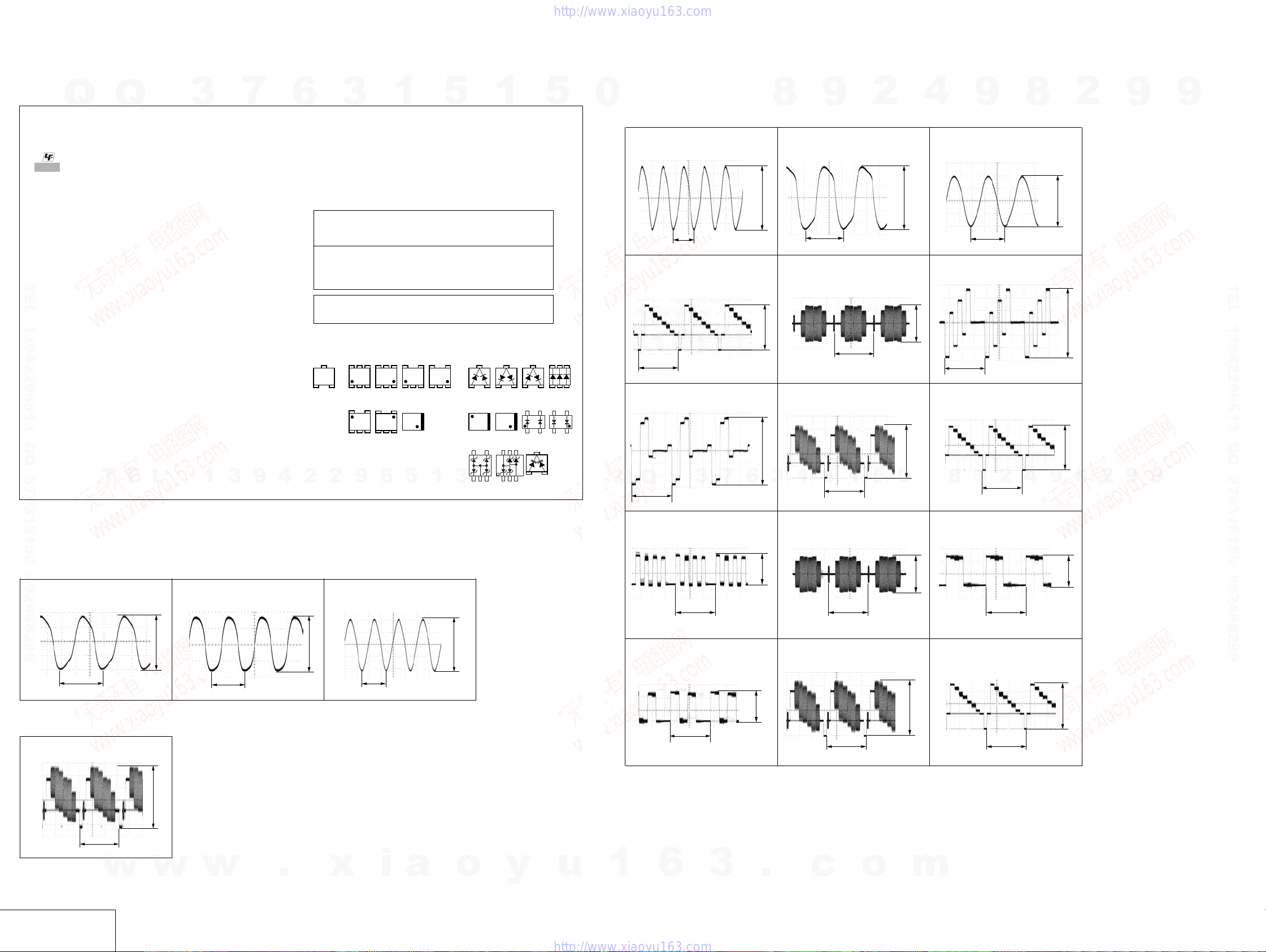
RDR-HX680/HX780/HX785/HX980/HX1080
4-2. SCHEMA TIC DIAGRAMS
3
7
9
4
6
2
3
• Readings are taken with a color-bar signals on DVD reference
disc.
• Readings are taken with a digital multimeter (DC 10MΩ).
•Voltage variations may be noted due to normal production tolerances.
Note : The components identified by mark 0 or dotted
Note : Les composants identifiés par une marque 0 sont
• Chip parts.
Transistor Diode
line with mark 0 are critical for safety.
Replace only with part number specified.
critiques pour la sécurité.
Ne les remplacer que par une pièce portant le numéro
spécifié.
When indicating parts by reference number, please
include the board name.
EB
2
5
5246
9
31
21
345
6
C
Q
THIS NOTE IS COMMON FOR SCHEMA TIC DIAGRAMS
(In addition to this, the necessary note is printed in each block)
(For printed wiring boards)
• : Uses unleaded solder.
• : Pattern from the side which enables seeing.
• Through hole is omitted.
• There are a few cases that the part printed on diagram
• C : panel designation
(For schematic diagrams)
• All capacitors are in µF unless otherwise noted. pF : µµF.
• All resistors are in ohms, 1/4 W (Chip resistors : 1 /10 W) un-less
TEL 13942296513 QQ 376315150 892498299
• Caution when replacing chip parts.
• All variable and adjustable resistors have characteristic curve B,
• 2 : non flammable resistor
• 5 : fusible resistor
• C : panel designation
• f : internal component
• C : adjustment for repair
• G : IN/OUT direction of (+/–) B line
• U : B+ Line
• V : B– Line
• Circled numbers refer to waveforms.
•Voltages are dc between measurement point and ground.
(The other layers’ patterns are not indicated)
isn’t mounted in this model.
50V or less are not indicated except for electrolytics and
tantalums.
otherwise specified.
kΩ=1000Ω, MΩ=1000kΩ.
New parts must be attached after removal of chip.
Be careful not to heat the minus side of tantalum capacitor, because it is damaged by the heat.
unless otherwise noted.
T
Q
E
L
3
1
1
654
123
12
534
5
5
54
45
123
312
43
12
1
3
3
21
21
34
5
1 3
1
3
21321
43
43
12
12
64
4
12
3
1
3
5
3
5.0 Vp-p
1.4 Vp-p
0
4
3 IC601 6 (X601)
6 JA402 Pb OUT
9 JA402 Y OUT
8
9
54.2 ns
H
9
2
H
8
4
0
AV-133/134 BOARD
1 IC101 qd (X101)
66.6 ns
4 JA401 3
31
H
4625
4
12
7 JA402 Pr OUT
Q
Q
H
3
7
5.0 Vp-p
1.8 Vp-p
6
1.0 Vp-p
8
2 IC101 q; (X102)
5 JA401 4
8 JA402 V OUT
3
1
9
30.5 ns
5
2
H
5
1
H
2.1 Vp-p
4.0 Vp-p
1.0 Vp-p
1.7 Vp-p
9
2
8
2
9
9
9
TEL 13942296513 QQ 376315150 892498299
9
WAVEFORMS
RD-066 BOARD
1 IC1001 (AF1) 2 IC5103 wd (X5101)
3.7 Vp-p
59 ns
FR-291
1 J201 VIDEO IN
BOARD
7
H
1.0 Vp-p
40.7 ns
3.2 Vp-p
3 IC5602 wd (X5502)
40 ns
2.1 Vp-p
q; JA501 7 B OUT
H
qd JA501 qg R OUT
H
1.2 Vp-p
1.2 Vp-p
qa JA501 qg C OUT
H
qf JA501 ql V OUT
H
1.4 Vp-p
2.2Vp-p
qs JA501 qa G OUT
1.2 Vp-p
H
qg JA501 ql Y OUT
1.8Vp-p
H
WAVEFORMS
AV-133/134 FR-291
RD-066
w
w
w
.
x
i
a
o
y
u
1
6
3
.
c
o
m
4-44-3
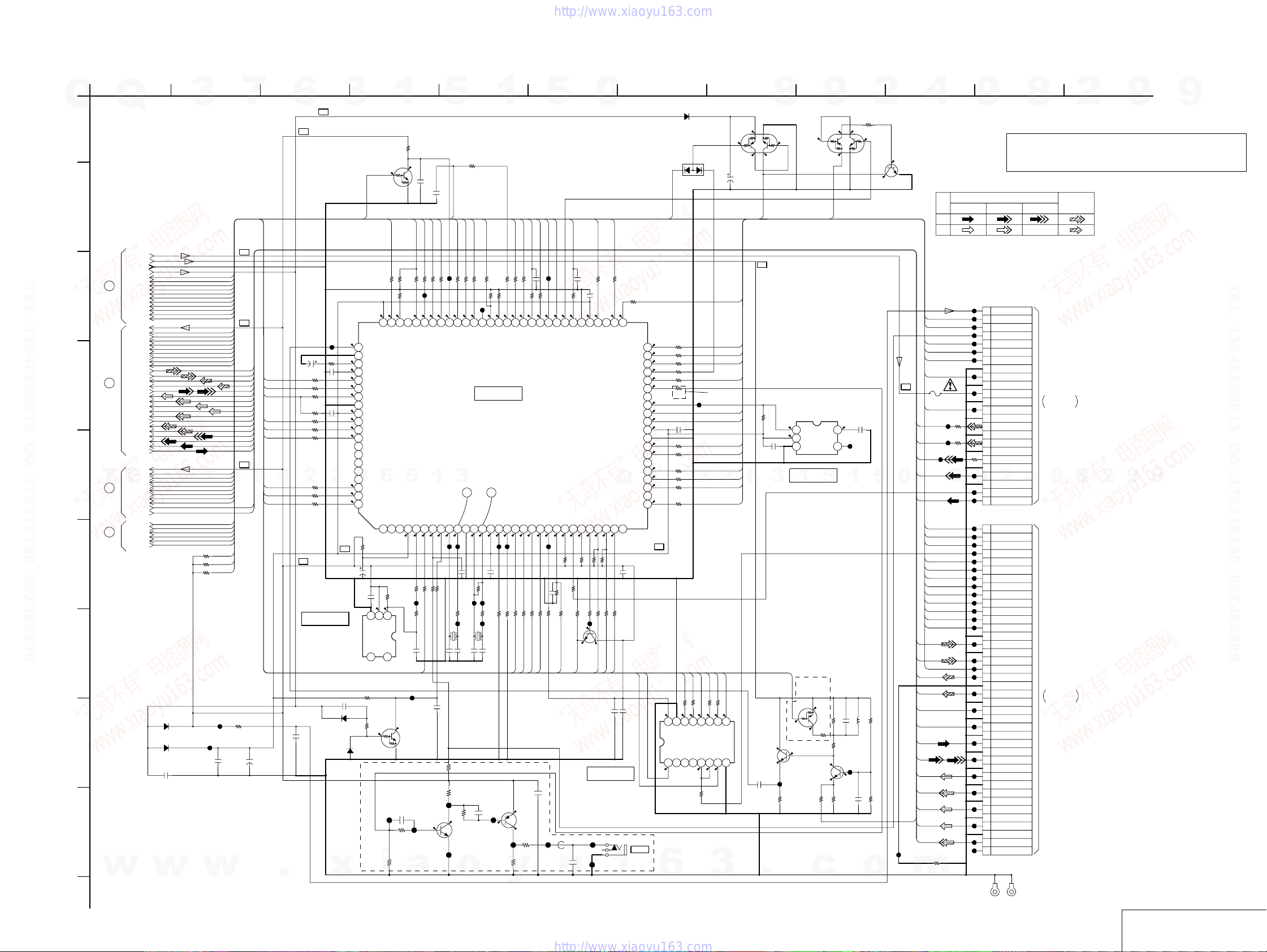
For Schematic Diagram
• Refer to page 4-4 for waveforms.
• Refer to page 4-51 for printed wiring board.
3 4 5 6 7 8 9 10 11 12
0
Q108
DTC124EUA-T106
BLANK
BLANK
R175
4.9
VDDDDA
CVBSIN
GND
FILTSLC
VDDVCO
DTBON
ANT5V_SW
DET_ANT
GND
VDD3
DBGP2
DBGP1
DBGP0
LED_PLTV
LED_DIVX
LED_D_TV
LED_A_TV
LED_HDD2
6
DAT_TO_M
DAM_TO_T
ASCK
NC
R104
47k
0.1
4.9
4.9
321
IN
NC GND
R112
10k
0
0
JL705
R755
4.7k
i
1
HST_TO_M
330
4.900
HST_TO_M
NC
R107
10k
OUT
NC
54
4.9
C752
100p
R753
4.7k
4
.
6
B+
R177
100
R178
100
R179
100
R233
100k
R180
100
R181
100
R182
100
2
R188
330
R189
470
R200
330
B+
C121
1
B+
JL113
R176
1k
C139
C138
2.2
0.1
50V
C140
0.1
IC102
ACDET
D101
1SS355TE-17
1SS355TE-17
3
2.0
2.9
4.9
4.8
4.9
4.9
4.9
4.9
2
3.2
B+
BD4846G-TR
C110
1
B
D102
x
0
0
0
0
C104
22
25V
IC102
81
82
83
84
85
86
87
88
89
90
91
92
93
94
95
96
97
9
98
99
100
C106
R113
Q
A
1
Q
AV-133 BOARD(1/5)
IT CONTROLLER, IR
3
2
7
-REF.NO.: 10,000 SERIES-
B
SWVION9V
P_CONT
P_CONT2
DET_ANT
ANT5V_SW
FANCTL
RFTHRU
SWVION5V
TU_DCCON
P_SAVE
CSYNCIN
RCSEL1
RCSEL2
XAMUTE2
AMUTE1
SAMUTE
FUNC_IN
FUNC_ON
AVLOUT
MSPSTAT
100k
100k
100k
DTBON
TUON
SCL
SDA
BLANK
BLANK
AVLTH
AVLIN
SQU
AFT
AGC
SCL
SDA
XRST1
DBGP2
DBGP1
DBGP0
3
B+
B+
L_IN
R_IN
R_OUT
L_OUT
Y_IN
C_OUT
Y_OUT
CB_OUT
CR_OUT
YP_OUT
TEXTVIN
L2_RIN
L2_LIN
2VIN
Y2IN
C2IN
C/R_IN
B+
BTOMAIN
GTOMAIN
9
DTBON
ANT5V_SW
DET_ANT
DBGP2
DBGP1
DBGP0
DAT_TO_M
DAM_TO_T
ASCK
(V+12R1E)
V+12R1
(V+5VI)
V+5VV
GND
V+5R8E
SWVION9V
T0 (2/5)
T0 (3/5)
T0 (4/5)
T0 (5/5)
P_CONT
P_CONT2
1
DET_ANT
ANT5V_SW
DTBON
FANCTL
RFTHRU
TUON
SWVION5V
TU_DCCON
V+5V
P_SAVE
CSYNCIN
SCL
SDA
RCSEL1
RCSEL2
BLANK
XAMUTE2
AMUTE1
L_IN
R_IN
R_OUT
2
L_OUT
Y_IN
C_OUT
Y_OUT
CB_OUT
CR_OUT
YP_OUT
TEXTVIN
L2_RIN
L2_LIN
2VIN
Y2IN
C2IN
C/R_IN
V+5V
SAMUTE
FUNC_IN
E
L
FUNC_ON
BLANK
3
AVLTH
AVLIN
AVLOUT
SQU
BTOMAIN
GTOMAIN
AFT
AGC
4
SCL
SDA
XRST1
MSPSTAT
1
R193
R194
R195
TEL 13942296513 QQ 376315150 892498299
C
D
E
T
F
G
R130
0
D103
H
1SS355TE-17
D104
1SR154-400TE-25
C120
0.1
JL109
C122
1
JL270
C118
0.22F
5.5V
I
w
w
w
J
4-5 4-6
R169
10k
4.9
C135
0.1
RXD1
TXD1
TU_DCCON
100
180
R199
R171
100
R168
R172
R174
100k
R173
100k
JL132
4.8
3.004.904.9
TXD1
RXD1
TXD2
RXD2
TU_DCCON
5
1
NC
WDT
ACDET
HSM_TO_TIRRESET
0
4.9
3.2
4.9
4.9
100
330
100
R105
R109
R110
JL272
R106
0
C105
0.1
HSM_TO_T
JL273
Q101
DTC124EUA-T106
RESET
JL707
0
JL706
Q752
2SC4081T106R
IR I/F SW
a
5
C134
0.1
MRST
HOTPLUG
100
R1670R159
JL140
BLANK
HOTPLUG
TX1
1.6
2.5
JL152
JL155
C107
100
R111
JL156
C1119pC112
8p
C109
0.1
R701
R751
1k
4.9
JL708
MSPSTAT
100
MSPSTAT
3
TX2
330p
R116
32.768kHz
R752
4.7k
o
1
R161
0
CEC0
AVLIN
CSYNCIN
0
R165
R160
AVLIN
3.600
100
JL149
CEC
R158
R157
100k
100k
NC(IN)
CSYNCIN
XCHECKER
R156
4.8
100
IC101
IT CONTROLLER
IC101
LC87F06J2A-F59P6-E
12
GND
CF1
CF2
VDD1
MODEL1
2.204.9
4.904.9
JL166
JL168
1
C113
1M
R117
0
15k
JL162
JL160
R228
R226
R118
0
0
JL163
X101
X102
15MHz
C114
C115
10p
10p
220k
C753
100p
JL709
4.9
Q751
2SA1576A-T106-QR
IR I/F SW
JL710
y
FLPON
SWVION5V
100
R155
R154
4.8
4.8
MRST
SWVION5V
MODEL2
KEY1
4.9
330
R124
R123
KEY1
KEY2
4.9
0
R756
1k
100
R153
100
4.7
FLON
KEY2
4.9
330
R129
R754
150
5
TUON
EPGEQ
P_CONT
SWVION9V
0.1
C133
JL167
R125
100
4.8
4.804.8
TUON
EPGEQ
P_CONT
SWVION9V
KEY3
AGC
BATTDET
FUNC
4.4
4.904.9
JL176
R133
100k
C124
0.1
100
330
R126
R127
10k
KEY3
FUNC_IN
AGC
C751
0.1
JL711 JL712
L751
0uH
u
P_CONT2
R151
0
4.7
P_CONT2
MUTECTL
SDET3
SDET2
4.904.9
R134
1k
R131
4.7k
R132
6.8k
AVLOUT
C132
4.9
R135
100k
R138
0
0
C754
100p
0.1
4.9
GND
AVLOUT
SDET1
470
0
FANCTL
R150
0.1
C131
2.7
VDD2
FANCTL
SDA
SCL
4.9
R139
6.8k
100
R137
R140
JL212
4.9
SDA0
SCL0
C141
10V
IC104
DDC SW
JL714
RFTHRU
0
4.8
NC
RFTHRU
Q
XRST
4.7
R141
6.8k
0
0
R142
XRST1
1
F
JA751
1
0
R149
R103
100
4.8
515253545556575859606162636465666768697071727374757677787980
FLCLK
FLSTB
FLDATA
AVLTH
XSCMUTE
P_SAVE
BLAIR
NC
CAPACITOR
SQUEEZE
FUNC_ON
VDD4
GND
DDCSW2
DDCSW1
NC
RCSEL2
RCSEL1
XAMUTE2
NC
AFT
NC
C125
0.1
100
R143
2SC4081T106R
CEC0
C142
1000p
50V
G-LINK
50
49
48
47
46
45
44
43
42
41
40
39
38
37
36
35
34
Q
33
32
31
Q102
RESET
DDC_SW2
D106
1SS355TE-17
D108
DAP202UT106
RESET
R102
4.9
100
R101
0
100
R148
0
100
R146
4.8
100
R152
0
0
0
4.8
0
0
4.9
4.9
4.7
0
4.9
4.9
0
B+
4.9
16 15 14 13 12 11 10 9
4.9
HX780: AEP1/ HX785 /
HX780: AEP1/ HX1080: AEP1
6
HX780: AEP1/ HX785 /
R201
0
HX780: AEP1/ HX1080: AEP1
JL192
C126
0.1
R205
100
R204
100
R202
0
R203
0
3
R144
0
R222
0
SDA
SDA0
DDC_SCL
DDC_SDA
R255
R223
R256
R224
100
100
0
0
4.9
4.3
4.9
4.9
IC104
TC7MB3257FK(EL)
3.6
3.6
R221
100
3
C127
100
16V
SCL
4.3
3.6
5.2
FLCLK
FLSTB
FLDATA
AVLTH
P_SAVE
SQU
FUNC_ON
DDC_SW2
DDC_SW1
RCSEL2
RCSEL1
7
XAMUTE2
AFT
SCL0
4.9
87654321
5.3
0
6
8
Q103
UMD2N-TR
11.7
SAMUTE
B+
R145
10k
C156
0.1
3
4.9
2.5
C152
1
10V
JL280
F
.
9
0
0
Q104
UMD2N-TR
IC103
BU4220G-TR
4.9
OUT
4.9
IN
321
GNDCTNC
IC103
5
1
IC101 VDD DET
HX780: AEP1/ HX785 /
HX780: AEP1/ HX1080: AEP1
Q110
EPGEQ
DTA143EVA-T106
EPGEQ
4.9
0
R208
0
4.9
3.2
Q112
2SC4081T106R
CV I/F
R217
1k
3.2
1.7
R216
750
c
2
R147
1k
0
0
4.8
0
11.7
C149
10p
50V
Q111
CV I/F
C157
0.1
B
C150
L102
47uH
1
10V
F
2SD2114KT146
5
R209
3.3k
R214
3.3k
AMUTE1
2.5
54
JL215
1
R207
470
R210
820
0.5%
2SC4081T106R
JL279
2.4
R215
680
o
Q103 - Q105
SAMUTE CONTROL
0
Q105
B+
0
R_OUT
L_OUT
BTOMAIN
GTOMAIN
C/R_IN
Y_IN
C_OUT
Y_OUT
CB_OUT
TEXTVIN
CR_OUT
YP_OUT
JL218
m
4
SIGNAL PATH
REC
PB
KEY1
KEY2
FLSTB
KEY3
FLCLK
FLDATA
IC150
0.5A
32V
FLPON
JL236
L2_RIN
JL237
L2_LIN
JL238
2VIN
Y2IN
8
C2IN
HOTPLUG
DDC_SW1
DDC_SCL
DDC_SDA
HST_TO_M
ASCK
DAT_TO_M
HSM_TO_T
DAM_TO_T
XRST1
MRST
P_CONT2
L_IN
R_IN
AMUTE1
R197
0
RDR-HX680/HX780/HX785/HX980/HX1080
R242
R241
9
8
2
9
Note : The components identified by mark 0 or dotted
line with mark 0 are critical for safety.
Replace only with part number specified.
VIDEO SIGNAL
CN105
24P
JL275
1
JL224
2
JL223
3
JL234
4
JL230
5
JL222
6
JL231
7
8
JL232
9
10
JL233
11
12
JL235
13
14
0
15
16
0
17
18
0
R240
19
20
JL239
21
9
22
JL240
23
JL241
24
CN101
40P
JL242
401234567891011 12 13 14 15 16 17 18 19 20 21 22 23 24 25 26 27 28 29 30
JL243
39
JL244
38
JL245
37
JL246
36
JL247
35
JL248
34
JL249
33
JL250
32
JL251
31
JL252
30
JL253
29
JL254
28
27
JL255
26
25
JL256
24
JL257
23
JL258
22
21
JL259
20
19
JL260
18
17
JL261
16
15
JL262
14
13
JL263
12
11
JL264
10
9
JL265
8
7
JL266
6
5
JL267
4
3
JL268
2
JL269
1
KN101 KN102
V+5F
KEY1
KEY2
IR
FLSTB
KEY3
FLCLK
GND
FLDATA
GND
V+12R1E
GND
FLPON
GND
2R
GND
2L
GND
2V
GND
2Y
2
GND
SDET2
2C
HPD
DDC_SW1
DSCL
CEC
DSDA
HST_TO_M
ASCK
DAT_TO_M
HSM_TO_T
DAM_TO_T
XRST1
MRST
P_CONT2
GND
L_IN
GND
R_IN
AMUTE1
R_OUT
GNDA
L_OUT
GND
B_IN
GND
G_IN
GND
C/R_IN
GND
Y_IN
GND
C_OUT
GND
Y_OUT
GND
CB_OUT
GND
CR_OUT
GND
YP_OUT
X525P
EE
Y/CHROMAYCHROMA
4
AUDIO
SIGNAL
TO FR-291
BOARD
CN202
THROUGH THE
FAR-008 FFC
(SEE PAGE 4-26)
8
9
TO RD-066
BOARD(3/7)
CN2301
THROUGH THE
FAR-006 FFC
(SEE PAGE 4-34)
2
9
IT CONTROLLER, IR
9
9
AV-133 (1/5)
TEL 13942296513 QQ 376315150 892498299
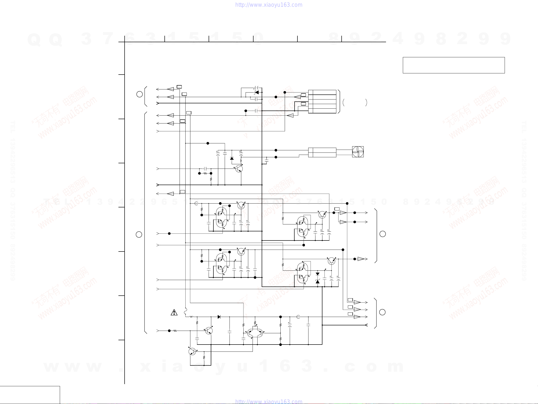
RDR-HX680/HX780/HX785/HX980/HX1080
For Schematic Diagram
• Refer to page 4-51 for printed wiring board.
1
3
Q
Q
3
7
6
AV-133 BOARD(2/5)
A
B
TEL 13942296513 QQ 376315150 892498299
POWER/FAN CONT.
-REF.NO.: 10,000 SERIES-
V+5VV
(V+5VI)
6
TO (4/5)
V+12R1
GND
V+5R8E
V+12R1
(V+12R1E)
P_CONT
1
2
5
B+
B+
B+
B+
1
3 4 5 6
5
JL319
0
C303
100
16V
UDZSNTPE-1715B
C301
0.1
25V
F
C302
0.1
25V
F
D301
JL330
JL329
8
CN301
5P
1
P_CONT
B+
2
EV+12.1V
3
GND
B+
4
EV+5.8V
5
GND
9
TO POWER
BLOCK
CN202
THROUGH THE
PAE-003 HARNESS
(SEE PAGE 4-44)
2
4
9
Note : The components identified by mark 0 or dotted
line with mark 0 are critical for safety.
Replace only with part number specified.
8
2
9
9
TEL 13942296513 QQ 376315150 892498299
T
E
L
1
3
9
C
D
4
E
F
G
H
2
1
TO (1/5)
2
FANCTL
GND
V+5VV
(V+5VI)
9
RFTHRU
SWVION5V
TUON
SWVION9V
TU_DCCON
6
JL301
JL302
B+
5
1
IC317
L304
0.5A
330uH
32V
R311
820
0.2
Q310
2SC4081T106R
JL307
3
L303
0uH
JL308
JL309
R310
C322
100p
0.6
R312
10k
4.7k
0.2
50V
C206
470p
50V
R219
3.3k
R304
100
C305
0.1
25V
F
R305
33
C309
0.1
25V
F
JL314
D201
C204
100
16V
JL311
R220
5.5
5.6
UMD2N-TR
+5V REG
1SS355TE-17
11.5
1SS355TE-17
C202
0.1
25V
F
Q201
2SD2114KT146
2.2k
FAN DRIVE
JL312
0
4.8
Q301
UMD2N-TR
+5V REG
JL313
0
4.8
Q303
D303
Q309
2SC5876T106QR
C205
22
25V
L201
1mH
0
0
5.6
JL315
5.5
C306
C307
0.1
100
25V
16V
F
5.6
JL316
5.5
C310
C311
0.1
220
16V
25V
F
R314
22k
C323
5.6
1
50V
F
C324
2012
0.1
25V
F
Q309 - 311
+32V SWITCHING
4.8
C308
100
16V
4.9
C312
100
16V
REG
Q
Q302
2SC4081T106R
+5V REG
2SD2153T100V
+5V REG
JL320
C329
0.1
25V
F
Q311
HN1A01FU-TE85R
R313
6.1
180k
5.7
0.6
C208
0.1
16V
B
Q304
JL325
JL326
Q
Q307
UMD2N-TR
+9V REG
JL327
R315
100k
0.5%
JL328
R306
33
5.5
Q305
UMD2N-TR
+5V REG
R309
1.5k
9.6
C326
10
50V
R316
22k
0.5%
CN201
2P
1
2
2SC2411K-T-146-CQ
+5V REG
7
3
0
4.7
C314
0.1
25V
JL338
Q308
2SC2411K-T-146-CQ
+9V REG
0
1SS355TE-17
0
4.7
D302
UDZSNTPE-179.1B
L305
0uH
C328
0.1
50V
F
FAN+
FAN-
Q306
6
5.6
5.5
F
D304
C315
100
16V
11.6
C318
0.1
25V
F
4.8
C316
9.6
3
100
16V
C319
JL341
100
16V
B+
8.9
C320
100
16V
1
JL346
JL343
5
B+
B+
B+
JL344
JL345
JL347
FAN
1
5
V+5VV
(V+5VO)
V+5VV
(V+5VI)
V+9V
V+5BB
V+5TU
V+32V
GND
0
5
TO (3/5)
7
TO (5/5)
8
9
2
4
9
8
2
9
9
w
POWER/FAN CONT.
AV-133 (2/5)
w
w
.
x
i
a
o
y
u
1
6
3
.
c
o
m
4-84-7
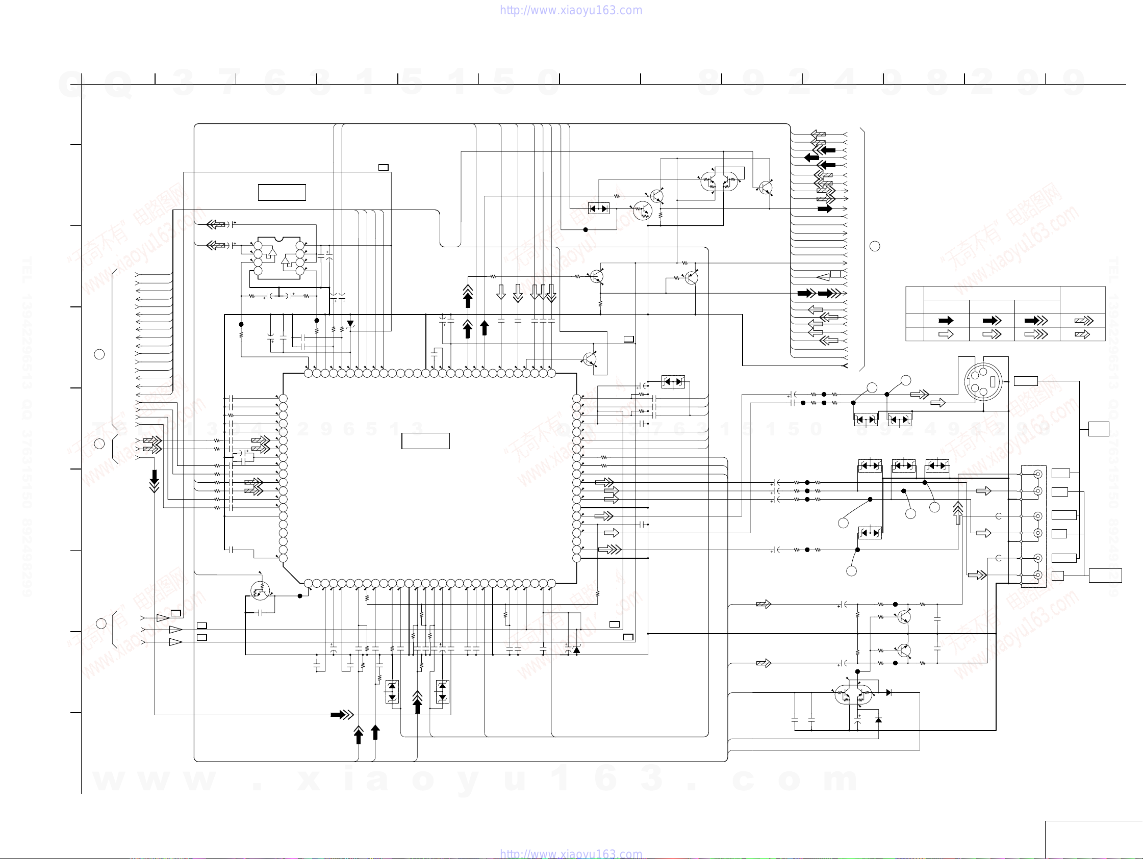
For Schematic Diagram
• Refer to page 4-4 for waveforms.
• Refer to page 4-51 for printed wiring board.
Q
1
Q
3
2
7
3 4 5 6 7 8 9 10 11 12 13
6
3
1
AV-133 BOARD(3/5)
VIDEO/AUDIO
A
-REF.NO.: 10,000 SERIES-
L_OUT
R_OUT
B
IC402
4.4
4.4
4.4
R454
10k
0.5%
C455
50V
1
R453
8.2k
0.5%
4321
4
0
C498
BA4558F-E2
--+
C471
10
50V
C452
100
10V
4.4
4.4
4.4
4.4
4.4
4.4
4.4
4.4
4.4
4.4
4.4
4.4
4.4
1.7
0.1
BUFFER
IC402
8765
+
R463
C474
8.2k
10
0.5%
50V
C403
100p
50V
C401
1
10V
C402
F
100p
50V
4.4
A HIFI IN(R)
81
A HIFI IN(L)
82
0
V DVD M C
83
A L4 IN(R)
84
A L4 IN(L)
85
2
2
A TUNER IN(R)
86
A TUNER IN(L)
87
VREF(9V/2)
88
A L3 IN(R)
89
A L3 IN(L)
90
A L2 IN(R)
91
A L2 IN(L)
92
A L5 IN(R)
93
A L5 IN(L)
94
GND
95
A AV1 R OUT(R)
96
A AV1 R OUT(L)
97
RF-C A OUT
98
A AGC D
99
VTR VorV&S V3 IN
100
2.2
JL402
100
16V
C451
C450
4.7
4.7
50V
50V
R403
560
560
4.4
4.4
F A DVD(L)
A DVD M C
F A DVD(R)
6
SEP Y1 IN
SYNC DET
SEO C1 IN
1.7
2.2
C456
1
50V
AV1_LOUT
D401
UDZSNPTE-1711B
8.9
4.4
VCC
A AV1/OUT(L)
SYNC DET OUT
SEP Y2 IN
1.7
C443
1
C500
R445
2012
Y2IN
C464
0.1
C473
25V
8.9
F
4.4
4.4
4.4
JL4424
R402
R462
10k
0.5%
4.4
To DVD(L)
To DVD(R)
9
V C&S C3 IN
DL3 DRIVE
123456789101112131415161718192021222324252627282930
2.2
1.7
C499
0.1 0.1
C475
10
50V
R_IN
C472
10
50V
L_IN
TEL 13942296513 QQ 376315150 892498299
C
AV2_V/YIN
AV1_V/YIN
AV2_V/YOUT
AV1_V/YOUT
RTOMAIN
RGBOUT
AV1_LOUT
AV1_ROUT
AV2_LOUT
8
TO (4/5)
T
9
TO (5/5)
AV2_ROUT
BIN
R/CIN
GIN
GOUT
R/COUT
BOUT
AV2_RIN
AV2_LIN
AV1_RIN
AV1_LIN
E
TU_RIN
TU_LIN
TU_VIN
D
E
F
G
5
(V+5VO)
TO (2/5)
(V+5VI)
H
I
V+9V
V+5VV
V+5VV
L
AV2_V/YIN
AV1_V/YIN
AV2_V/YOUT
AV1_V/YOUT
RTOMAIN
RGBOUT
AV1_LOUT
AV1_ROUT
AV2_LOUT
AV2_ROUT
BIN
R/CIN
GIN
GOUT
R/COUT
BOUT
B+
1
R408
3
470
R413
470
R414
470
R415
470
R416
L2_RIN
470
R417
L2_LIN
470
R418
470
R419
470
P_SAVE
DTC124EUA-T106
B+
B+
9
C497
0.1
Q401
SW
C414
0.1
C415
0.1
R422
10k
C468
0.1
C469
0.1
C411
1
C412
C419
1
C420
C421
C422
C423
C424
JL4423
4.7
1
C418
1
1
1
1
1
AV1_ROUT
AV2_LOUT
4.4
4.4
A AV2/OUT(L)
A AV1/OUT(R)
5
SYNC DET
SEP C2 IN
0.5
2.2
R425
100k
C431
R430
1M
75
R444
75
2012
C2IN
B+
AV2_ROUT
4.4
A AV2/OUT(R)
A HorHDD/OUT(L)
1
S1/S2 B OUT
59/61PIN
0
1.7
0.1
R428
0
C432
1
C447
10V
0.01
B
5
C413
0.1
16V
VIDEO AGC
A AV1/OUT2(L)
A AV1/OUT2(R)
A HorHDD/OUT(R)
3
IC401
VIDEO/AUDIO
SELECTOR
IC401
HA118326APFR-E
VIDEO L3 IN
GND
VIDEO L2 IN
FBC
2.6
2.1
R421
1M
R431
R432
1M
C428
C444
1
0.1
10V
16V
B
B
R447
75
2012
D421
NNCD3.9F-T1B
AV2_V/YIN
AV1_V/YIN
2VIN
1
C453
100
10V
B
2.1
2.1
4.9
MAIN C D
MAIN C IN
VIDEO L1 INBGBS IN
1.8
2.8
1.8M
C446
1
C457
10
50V
RTOMAIN
C404
1
10V
F
2.202.2
VCC
SLICER OUT
RS IN D OUT
1.8
1.7
C445
1
C496
0.1
25V
F
D422
NNCD3.9F-T1B
5
BLANK
R460
0
C406
0.1
16V
B
DVD C OUT
PAL SCART IN
DVD VorY OUT
PAL SCART D2
TUNER IN
FBCD
AV2 OUT
GND
2.6
2.4
C434
0.1
16V
B
AV2_V/YOUT
0
RCSEL1
C_OUT
2.2
F DVD C
VTR OUT
R420
1.8M
2.6
C440
0.1
16V
B
C407
Y_OUT
C408
1
10V
10V
B
2.202.2
F DVD Y
RGB M OUT
PAL SCART D1
FBCD
V1 OUT
VCC
2.3
4.9
C441
1
10V
F
CB_OUT
CR_OUT
C409
C410
1
1
10V
B
B
2.2
F dvd Pr(R)
F DVD Pb(B)
C1 OUT
VCC
4.9
C442
0.1
25V
F
RCSEL2
YP_OUT
RGBOUT
1
10V
B
2.2
515253545556575859606162636465666768697071727374757677787980
F DVD PY(G)
SCART B IN
SCART RorC IN
SCART G IN
VCC
PY(Y)G OUT
Q
Pr(Cr)/RorC OUT
Pb(Cb)/B OUT
SCL
SDA
SYNC
PY(Y)OUT
Pr(Cr)/OUT
Pb(Cb)/OUT
GND
V2 OUT
FBCD
C2 OUT
S1/S2 B OUT
V2 OUT
GND
Y1 OUT
2.4
C458
100
10V
AV1_V/YOUT
D420
DAP202UT106
JL487
4.9
2.2
R810
47
1.5
Q801
2SC4081T106R
BUFFER
R811
470
4.9
2SD2114KT146
0
0
1.7
50
2.2
49
1.7
48
4.9
47
0.4
46
Q
0.4
45
0.3
44
43
42
41
40
39
38
37
36
35
34
33
32
31
R436
4.4
100
R437
4.5
100
0.3
2.4
2.4
2.4
2.4
2.7
2.4
2.3
R439
1.8M
D402
UDZSNPTE-176.8B
R465
470
0
Q413
DTC124EUA-T106
B+
Q402
BUFFER
R433
1M
R435
1M
3
B+
B+
Q410
2SC4081T106R
BUFFER
2.2
SW
C454
100
10V
C435
1
7
C438
1
10V
F
C439
0.1
16V
B
Q411
UMD2N-TR
0
SW
4.9
1.6
R461
680
R458
470
1.5
R455
47
Q403
2SA1576A-T106-QR
BUFFER
D801
UMZ6.8N-T106
6
BIN
R/CIN
GIN
GOUT
3
R/COUT
BOUT
C436
1
C437
1
8
4.8
4.9
2.2
1
SCL
SDA
CSYNCIN
9
4.8
0
Q408
2SC4081T106R
BUFFER
5
L_OUT
R_OUT
AMUTE1
V+5V
XAMUTE2
C489
470
1
6.3V
4.9
1.6
C487
470
6.3V
C488
470
6.3V
C490
470
6.3V
2
C486
470
6.3V
C476
0.01
16V
B
5
R472
68
R476
68
R474
68
R478
2012
C463
0.1
25V
F
L_OUT
R_OUT
2VIN
C2IN
Y2IN
L2_RIN
L2_LIN
R_IN
L_IN
SCL
SDA
CSYNCIN
RCSEL1
RCSEL2
P_SAVE
AMUTE1
V+5V
XAMUTE2
BLANK
C_OUT
Y_OUT
CB_OUT
CR_OUT
YP_OUT
L_OUT
R_OUT
R468
2012
JL4407
JL4408
JL4409
JL4410
68
R470
2012
0
4
B+
R469
68
3.9
JL4418
2012
JL4419JL4420 JL4421
R471
0
75
2012
R473
3.9
R477
3.9
R475
3.9
6
R480
3.9
2012
C491
16V
C493
47
16V
0
C481
0.1
25V
F
RDR-HX680/HX780/HX785/HX980/HX1080
L_OUT
R_OUT
2VIN
C2IN
Y2IN
L2_RIN
L2_LIN
R_IN
L_IN
C/R_IN
SCL
SDA
CSYNCIN
RCSEL1
RCSEL2
P_SAVE
TEXTVIN
AMUTE1
V+5V
XAMUTE2
Y_IN
BLANK
C_OUT
Y_OUT
CB_OUT
CR_OUT
YP_OUT
L_OUT
R_OUT
GND
D409
8
UMZ6.8N-T106
UMZ6.8N-T106
UMZ6.8N-T106
JL4414
8
R485
47
22k
R487
22k
JL494
4.9
0
4.9
C492
220
10V
2
TO (1/5)
5
D413
JL4413
D416
R479
470
R484
1k
R486
1k
R488
470
4.9
9
REC
4
JL4422
D410
2
9
UMZ6.8N-T106
D414
UMZ6.8N-T106
JL4412
7
JL495
0
0
JL4406
D419
1SS355TE-17
Q404
UMD2N-TR
MUTE
D418
1SS355TE-17
8
SIGNAL PATH
VIDEO SIGNAL
PB
9
4
D415
UMZ6.8N-T106
JL4411
9
Q406
2SD2114KT146
SW
0
R482
100
C482
470p
50V
Q407
2SD2114KT146
C484
470p
SW
R490
100
50V
0
2
1
3
4
2
8
JA401
2
L801
0uH
L802
0uH
G
9
Y/CHROMAYCHROMA
S VIDEO
9
JA402
V
L
R
9
VIDEO
PR/C
AUDIO L
PB/C
AUDIO R
Y
9
R
B
AUDIO
SIGNAL
TEL 13942296513 QQ 376315150 892498299
LINE 2
OUT
COMPONENT
VIDEO OUT
w
w
w
.
x
i
a
o
y
u
1
6
3
.
c
o
m
4-9 4-10
VIDEO/AUDIO
AV-133 (3/5)
 Loading...