

Sony PVS-1240S Operating Instructions Manual

MATRIX SWITCHER
PVS-1240S
Operating Instructions
Thank you for purchasing this Sony product. Please be sure
to read this manual before using this product. After reading,
keep the manual in a safe place for future reference.
2-346-506-11 (1)
Table of Contents
Warning .......................................................................................2
Precautions .................................................................................. 3
Dimensions ..................................................................................4
Block diagram ............................................................................. 4
Location and functions of parts ................................................5
Using the memory functions ....................................................7
REMOTE parallel input port...................................................10
RS-232C port .............................................................................. 11
Troubleshooting guide.............................................................12
Specifications ............................................................................. 13
Features
PVS-1240S is the matrix switcher that has twelve inputs and
four outputs.
A/V 12-Input 4-Output Full-Matrix Functions
Composite-video-signal and audio (stereo) consists of 1 to
12 channels for input and 1 to 4 channels for output. For
S-video (Y/C) is available in 1 to 4 for both input and
output channels. Signals from any input channel can be
routed to any, some or all of the output channels.
Memory Functions
Settings made using the Crosspoint buttons can be stored in
nonvolatile memory and retrieved as required.
Remote and RS-232C Ports
The REMOTE parallel port allows you make settings from
an external location the same as with the Crosspoint
buttons. The RS-232C port is provided to control the PVS1240S from the SRP-C5000 system controller or a PC.
Reference Signals
This unit equips a reference video terminal for synchronized
switching without momentary deterioration of picture
quality.
LOCK Switch
Use this switch to prevent against inadvertent operation.
C 1998 by Sony Sound Tec Corporation
Printed in Japan
1

WARNING
English
WARNING
To prevent fire or shock hazard, do not expose the unit
top rain or moisture.
To avoid electrical shock, do not open the cabinet. Refer
servicing to qualified personnel only.
This unit can be used in a commercial district or a light
industrial area. This unit conforms with the limits for the
EN 55022 Class B.
Français
AVERTISSEMENT
Afin d’éviter tout risque d’incendie ou d’électrocution,
ne pas exposer l’appareil à la pluie ou à l’humidité.
Afin d’écarter tout risque d’électrocution, garder le
coffret fermé. Ne confier l’entretien de l’appareil qu’à un
personnel qualifié.
Español
ADVERTENCIA
Para evitar incendios o el riesgo de electrocución, no
exponga la unidad a la lluvia ni a la humedad.
Para evitar descargas eléctricas, no abra la caja. En caso
de avería solicite los servicios de personal cualificado
solamente.
Svenska
VARNING
Utsätt inte apparaten för regn och fukt för att undvika
riskerna för brand och/eller elektriska stötar.
Öppna inte höljet. Det kan resultera i risk för elektriska
stötar. Överlåt allt reparations- och underhållsarbete till
fackkunniga tekniker.
Italiano
ATTENZIONE
Per evitare il pericolo di incendi o scosse elettriche,
l’apparecchio non deve essere esposto alla pioggia o
all’umidià.
Per evitare scosse elettriche, non aprire l’apparecchio.
Per le riparazioni rivolgersi solo a personale qualificato.
Norsk
ADVARSEL
For å hindre brann og støtfare må enhetens overflate
ikke utsettes for regn eller fuktighet.
For å unngå elektrisk støt må kassen ikke åpnes. Service
må bare utføres av kvalifisert personell.
Suomi
VAROITUS
Deutsch
VORSICHT
Um die Feuergefahr und die Gefahr eines elektrischen
Schlages zu vermeiden, darf das Gerät weder Regen
noch Feuchtigkeit ausgesetzt werden.
Um einen elektrischen Schlag zu vermeiden, darf das
Gehäuse nicht geöffnet werden. Überlassen Sie
Wartungsarbeiten stets nur einem Fachmann.
Dieses Produkt kann im kommerziellen und in begrenztem
Maße auch im industriellen Bereich eingesetzt werden. Das
Gerät hält die für EN 55022 Klasse B vorgeschriebenen
Grenzwerte ein.
Nederlands
WAARSCHUWING
Stel het apparaat niet bloot aan regen of vocht, om
gevaar van brand of een elektrische schok te
voorkomen.
Open niet de behuizing, om gevaar van elektrische
shokken te vermijden. Laat reparatiles aan de erkende
vakhandel over.
Tulipalon ja iskuvaaran välttämiseksi ei laitetta saa
altistaa sateelle ja kosteudelle.
Sähköiskun välttämiseksi ei koteloa saa avata. Anna
vain asiantuntijan suorittaa huolto.
Dansk
ADVARSEL
For at undgå faren for brand eller elektrisk stød må
udstyret ikke udsættes for regn eller kraftig fugt.
Åbn ikke kabinettet, da der er risiko for elektriske stød.
Overlad alle reparationer til kvalificeret
servicepersonale.
Português
ADVERTÊNCIA
Para evitar o risco de incêndio ou de choques eléctricos,
não exponha o aparelho à chuva nem à humidade.
Para evitar descargas eléctricas, não abra o aparelho.
Peça assistência somente a técnicos especializados.
2
Precautions
Notice for the Customers in the United Kingdom
IMPORTANT
The wires in this mains lead are coloured in accordance
with the following code:
Blue: Neutral
Brown: Live
As the colours of the wires in the mains lead of this
apparatus may not correspond with the coloured markings
identifying the terminals in your plug, proceed as follows:
The wire which is coloured blue must be connected to the
terminal which is marked with the letter N or coloured
black. The wire which is coloured brown must be connected
to the terminal which is marked with the letter L or
coloured red.
Do not connect either wire to the earth terminal in the plug
which is marked by the letter E or by the safety earth
symbol Y or coloured green or green-and-yellow.
This symbol is intended to alert the user to
the presence of uninsulated “dangerous
voltage” within the product’s enclosure that
may be of sufficient magnitude to constitute
a risk of electric shock to persons.
This symbol is intended to alert the user to
the presence of important operating and
maintenance (servicing) instructions in the
literature accompanying the appliance.
On safety
• Set the VOLTAGE SELECTOR to the position of your local
power line voltage before connecting the AC power cord
to a wall outlet. If the plug of the AC power cord does not
fit the outlet, use the supplied plug adaptor.
• Should any liquid or solid object fall into the cabinet,
unplug the unit and have it checked by qualified
personnel before operating it any further.
• Unplug the unit from the wall outlet if it is not to be used
for an extended period of time. To disconnect the cord,
pull it out by grasping the plug. Never pull the cord itself.
On installation
Do not install the unit in a location near heat sources such as
radiators or air ducts, or in a place subject to direct sunlight,
excessive dust, mechanical vibration or shock.
On operation
• Before making program source connections, be sure to
turn the power switch off and unplug the unit.
• When the unit is not used, turn the power off to conserve
energy and to extend the useful life of your unit.
On cleaning the cabinet
Clean the cabinet, panel and controls with a soft cloth
lightly moistened with mild detergent solution. Do not use
any type of abrasive pad, scouring powder or solvent such
as alcohol or benzine.
*The location of the marking is on the rear enclosure.
On repacking
Do not throw away the carton and the packing material. It
makes an ideal container to transport the unit in.
When shipping the unit for repair work or to another
location, repack it as it was.
If you have any questions or problems concerning your
unit, please contact your nearest Sony dealer.
3
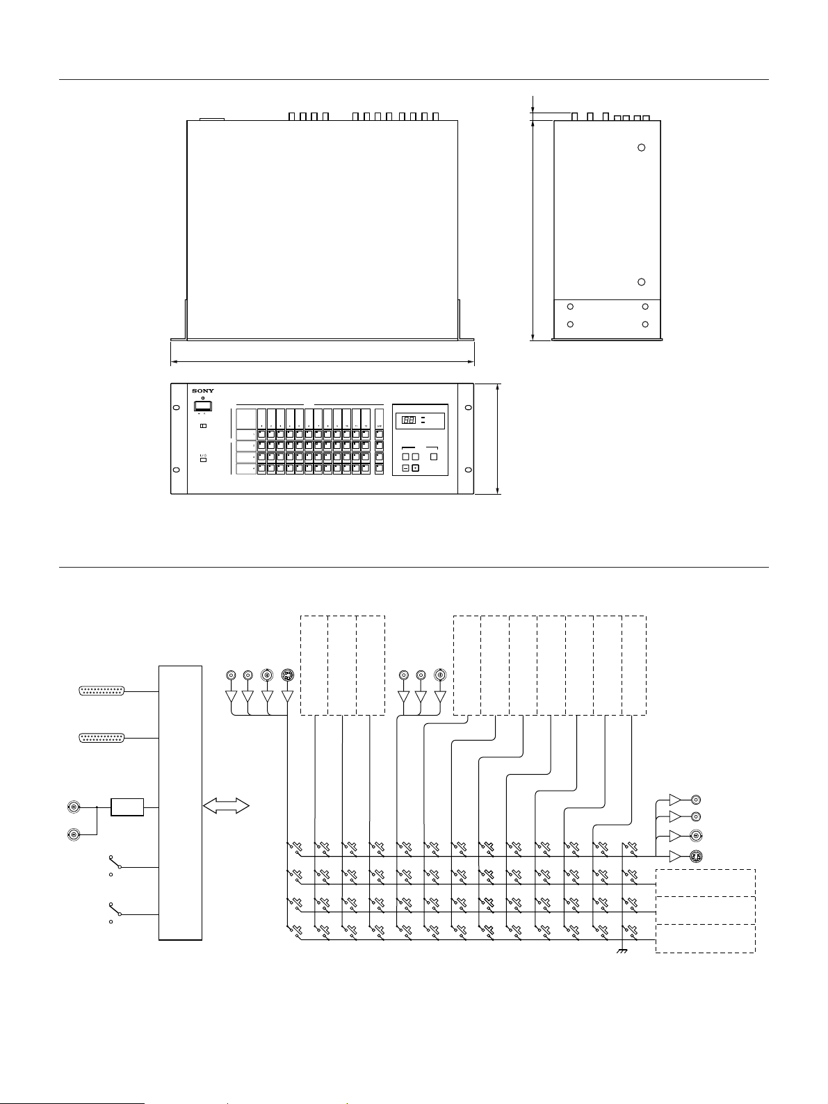
Dimensions
11
350
POWER
ON OFF
ON OFF
OUTPUT
ON/STANDBY
Block Diagram
AUDIO(PHONO)
–10dBu
VIDEO
RS-232C
L
INPUT 1
REMOTE
S-VIDEO
R
482
INPUT
INPUT 2
(SAME AS INPUT 1)
INPUT 3
MEMORY NUMBER
RECALL STORE
(SAME AS INPUT 1)
INPUT 4
(SAME AS INPUT 1)
INPUT 5
AV SEPARATE
REMOTE
MEMORY
ENTER
NUMBER
MATRIX SWITCHER PVS-1240S
AUDIO(PHONO)
–10dBu
L
R
VIDEO
INPUT 6
176
(SAME AS INPUT 5)
INPUT 7
(SAME AS INPUT 5)
INPUT 8
Unit : mm
(SAME AS INPUT 5)
INPUT 9
(SAME AS INPUT 5)
INPUT 10
(SAME AS INPUT 5)
INPUT 11
(SAME AS INPUT 5)
INPUT 12
(SAME AS INPUT 5)
VIDEO REFERENCE
INPUT
LOCK
ON/STANDBY
4
ON
OFF
V.SYNC
CONTROL
OFF
OUTPUT 1
L
AUDIO(PHONO)
–10dBu
R
VIDEO
S-VIDEO
OUTPUT 2
(SAME AS OUTPUT 1)
OUTPUT 3
(SAME AS OUTPUT 1)
OUTPUT 4
(SAME AS OUTPUT 1)
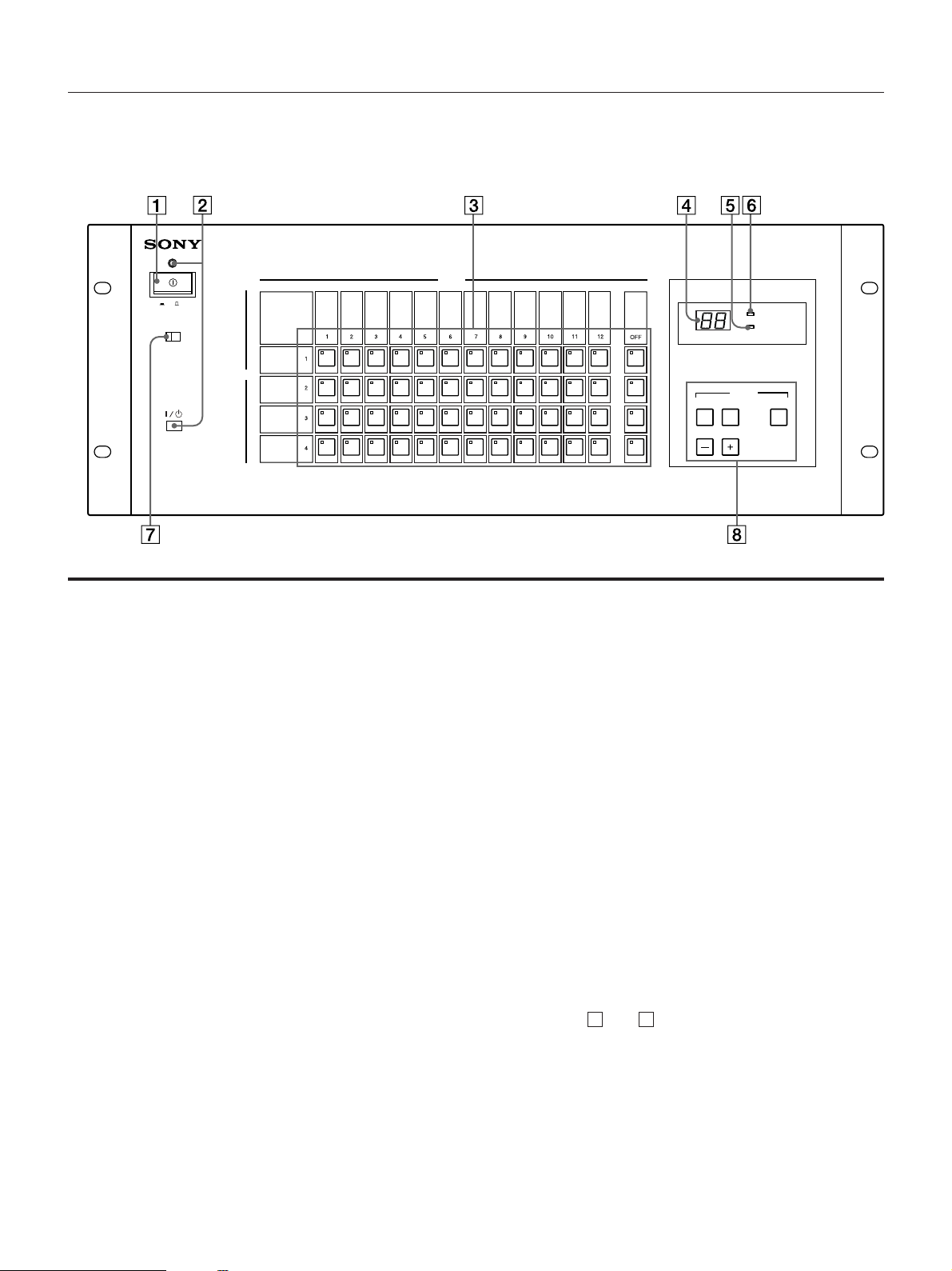
Location and Functions of Parts
Front panel
INPUT
ON OFF
ON OFF
OUTPUT
MEMORY NUMBER
RECALL STORE
MEMORY
AV SEPARATE
REMOTE
ENTER
ON/STANDBY
1 POWER Switch
Press to turn this unit on/off.
2 ON/STANDBY Switch and Pilot Lamp
Press to switch between operating mode (the pilot lamp
lights up green) and standby mode (the pilot lamp lights
up red.)
3 Crosspoint Buttons
Use these buttons to route the AV signals through any of
outputs, or to stop routing.
For each of the output channels 1 to 4, choose a channel
that is to be the input channel and press the numbered
button or the OFF button in that row. The indicator of the
button you have just pressed lights up.
4 MEMORY NUMBER Display
Displays MEMORY NUMBERs 01 to 50.
NUMBER
MATRIX SWITCHER PVS-1240S
6 A/V SEPARATE Indicator
The indicator lights up when the A/V SEPARATE
function is used from the control signal via the RS-232C
port. The indicator goes OFF only when the Crosspoint
buttons on the front panel are pressed and there is no AV
SEPARATE status displayed. The A/V SEPARATE
function can be used only via the RS-232C interface.
For further details, see page 11.
7 LOCK Switch
Setting the LOCK switch to ON disables operation of the
buttons on the front panel. For safety reasons, operation
of the POWER and ON/STANDBY switches cannot be
locked out.
For operation from an external location using the
REMOTE or RS-232C port on the rear panel, be sure to set
the LOCK switch to ON in order to avoid inconsistent
operations of this unit caused by operation with the
Crosspoint buttons.
5 REMOTE Indicator
The indicator lights up when this unit is controlled from a
control signal via the REMOTE and RS-232C ports on the
rear panel. Pressing the Crosspoint buttons on the front
panel turns the indicator OFF.
8 MEMORY Operation Buttons
NUMBER and , RECALL, STORE and ENTER
Use these buttons to store the settings of the Crosspoint
buttons in memory, or to recall the stored settings
(MEMORY RECALL). For details on operation of these
buttons, see page 7.
+ –
(continued)
5
 Loading...