

Sony PVP-MSH Service manual
PVP-MSH
SERVICE MANUAL
Ver 1.0 2001. 03
SPECIFICATIONS
Print method: Variable dot thermal transfer
Print resolution: 254 dpi
Number of printed dots: 640 × 480 (paper feed direction)
Print speed: 3.05 mm (1/8 in.)/second
Size of print pape: 91 × 55 mm (3 5/8 × 2 1/4 in.)
Print area size: 64 × 48 mm (2 5/8 × 1 15/16 in.)
Printing time (approx.): 160 seconds
Number of prints per print cartridge roll: 20
Power consumption: 5 W
Guaranteed operating temperature for printing:
10 °C to 35 °C (50 °F to 95 °F)
Storage temperature: -20 °C to + 55 °C (-4 °F to +131 °F)
Print cartridge storage temperature: -20 °C to + 55 °C (-4 °F to +131 °F)
Dimensions (approx.):
67 × 78 × 97 mm (2 3/5 × 3 1/10 × 3 4/5 in.) (h/w/d)
Mass (approx.): 305 g (10 3/4 oz)
US Model
Canadian Model
AEP Model
PORTABLE VIDEO PRINTER

TABLE OF CONTENTS
SERVICE NOTE
1. POWER SUPPLY DURING REPAIRS ·····························3
1. GENERAL
Before Y ou Begin
Identifying the parts and lamp indications·····························1-1
Preparation
Inserting the print cartridge ··················································· 1-1
Attaching the printer ······························································ 1-2
Preparing the power supply ···················································1-2
Inserting the print paper·························································1-3
Making prints - Standard print
Printing images whenever you want to·································· 1-3
Printing images recorded on “Memory Stick”·······················1-4
Printing images with the date ················································1-4
Making prints of split screens - Split printing
Printing a single image ··························································1-5
Printing images recorded on “Memory Stick” in recording
order ·······················································································1-5
Printing images with print marks··········································· 1-5
Additional Information
Precautions············································································· 1-5
Troubleshooting ·····································································1-6
Maintenance information·······················································1-7
2. DISASSEMBLY
2-1. PRINTER UNIT SECTION ············································2-1
2-2. CABINET (UPPER) SECTION······································ 2-1
2-3. PRINTER UNIT (PR-036, SW-352 BOARDS)··············2-2
2-4. CONNECTOR PLUG (HOT SHOE)······························2-3
2-5. CABINET (LOWER) SECTION ····································2-3
2-6. SHOE ADJUSTER··························································2-4
2-7. SHOE RETAINER CAM ASSEMBLY ··························2-5
3. BLOCK DIAGRAMS
3-1. OVERALL BLOCK DIAGRAM ····································3-1
4. PRINTED WIRING BOARDS AND
SCHEMATIC DIAGRAMS
4-1. FRAME SCHEMATIC DIAGRAM································4-1
4-2. PRINTED WIRING BOARDS AND
SCHEMATIC DIAGRAMS ············································4-4
• SW-352 (PRINT SW)
PRINTED WIRING BOARD AND
SCHEMATIC DIAGRAM······························4-5
• PR-036 (PRINTER CONTROL, SYSTEM CONTROL,
DC/DC CONVERTER)
PRINTED WIRING BOARD ·························4-7
• PR-036 (PRINTER CONTROL)(1/3)
SCHEMATIC DIAGRAM······························4-9
• PR-036 (SYSTEM CONTROL)(2/3)
SCHEMATIC DIAGRAM····························4-11
• PR-036 (DC/DC CONVERTER)(3/3)
SCHEMATIC DIAGRAM····························4-13
4-3. WAVEFORMS ······························································4-16
4-4. MOUNTED PARTS LOCATION ·································4-16
5. ADJUSTMENTS
1. ADJUSTMENT·······························································5-1
1-1. PREPARATIONS BEFORE ADJUSTMENTS ··············5-1
1-1-1.Equipment to Required····················································5-1
1-1-2.Connecting the Equipment ··············································5-1
1-1-3.Confirmation of the Adjustment RV. ·······························5-1
1-2. Printer Head Voltage Adjustment
(Without Adjustment RV) (PR-036 board)······················5-2
1-3. Printer Head Voltage Adjustment
(With Adjustment RV) (SW-352 board)··························5-3
6. REPAIR PARTS LIST
6-1. EXPLODED VIEWS ······················································ 6-1
6-1-1.OVERALL SECTION·····················································6-1
6-2. ELECTRICAL PARTS LIST ··········································6-2
SAFETY-RELATED COMPONENT WARNING!!
COMPONENTS IDENTIFIED BY MARK 0 OR DOTTED LINE WITH
MARK 0 ON THE SCHEMATIC DIAGRAMS AND IN THE PARTS
LIST ARE CRITICAL TO SAFE OPERATION. REPLACE THESE
COMPONENTS WITH SONY PARTS WHOSE PART NUMBERS
APPEAR AS SHOWN IN THIS MANUAL OR IN SUPPLEMENTS
PUBLISHED BY SONY.
SAFETY CHECK-OUT
After correcting the original service problem, perform the following
safety checks before releasing the set to the customer.
1. Check the area of your repair for unsoldered or poorly-soldered
connections. Check the entire board surface for solder splashes
and bridges.
2. Check the interboard wiring to ensure that no wires are
"pinched" or contact high-wattage resistors.
3. Look for unauthorized replacement parts, particularly
transistors, that were installed during a previous repair . Point
them out to the customer and recommend their replacement.
ATTENTION AU COMPOSANT AYANT RAPPORT
À LA SÉCURITÉ!
LES COMPOSANTS IDENTIFÉS P AR UNE MARQUE 0 SUR LES
DIAGRAMMES SCHÉMA TIQUES ET LA LISTE DES PIÈCES SONT
CRITIQUES POUR LA SÉCURITÉ DE FONCTIONNEMENT. NE
REMPLACER CES COMPOSANTS QUE PAR DES PIÈSES SONY
DONT LES NUMÉROS SONT DONNÉS DANS CE MANUEL OU
DANS LES SUPPÉMENTS PUBLIÉS PAR SONY.
4. Look for parts which, through functioning, show obvious signs
of deterioration. Point them out to the customer and
recommend their replacement.
5. Check the B+ voltage to see it is at the values specified.
6. Flexible Circuit Board Repairing
• Keep the temperature of the soldering iron around 270˚C
during repairing.
• Do not touch the soldering iron on the same conductor of the
circuit board (within 3 times).
• Be careful not to apply force on the conductor when soldering
or unsoldering.
— 2 —
SERVICE NOTE
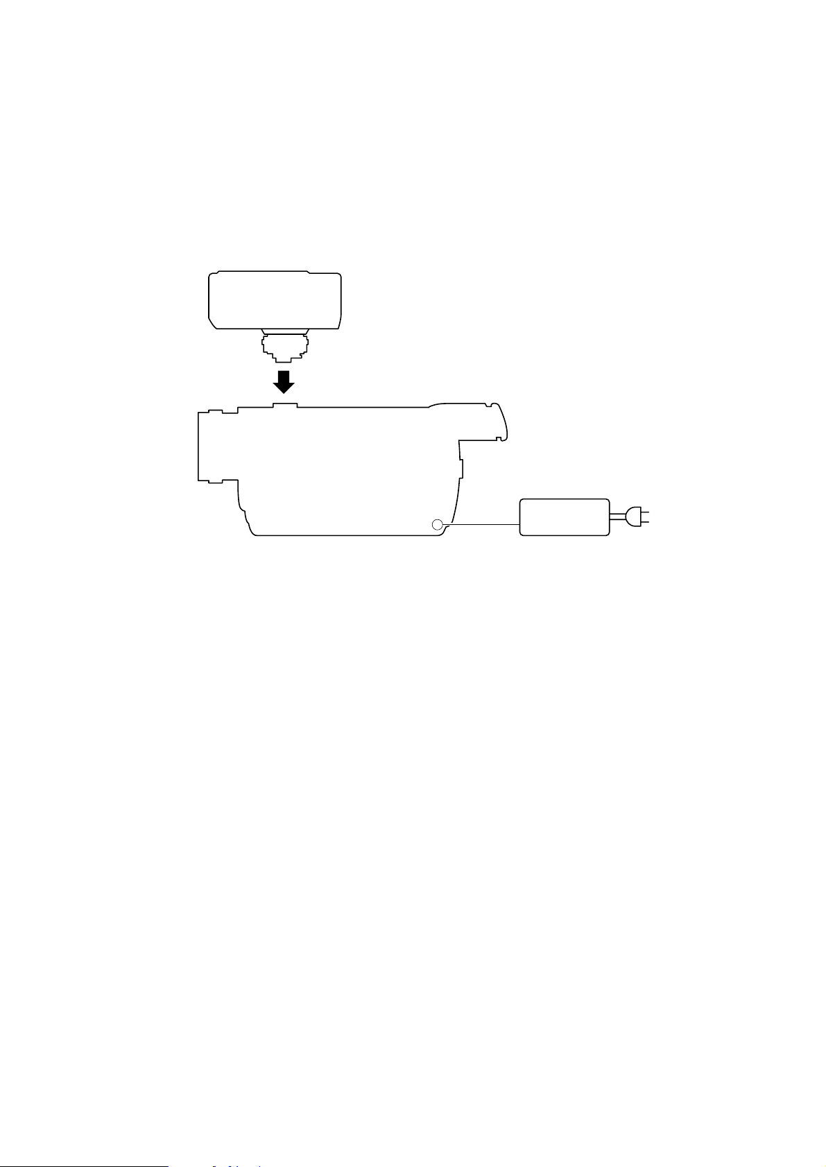
1. POWER SUPPLY DURING REPAIRS
Connect this printer to the Intelligent accessory shoe (15P) of the camcorder suitable for this printer, and repair/adjust this printer.
Camcorders suitable for this printer are shown in the following.
DCR-TRV830/TRV830E, etc.
Switch setting of the camcorder:
POWER................................................................. MEMORY
Printer
Intelligent accessory shoe (15P)
Camcorder
DC IN jack
AC power adaptor
AC-L10,
AC-VQ800 etc.
AC IN
— 3 —
SECTION 1
GENERAL
PVP-MSH
This section is extracted from
instruction manual.
BBefore You Begin
Identifying the parts and lamp indications
Printer cover
PRINT button
POWER lamp
PAPER lamp
CARTRIDGE lamp
POWER lamp (green)
Lit
•The printer cover is open.
PAPER lamp (red)
Fast flashing
•Print paper error
Slow flashing
•Print paper not inserted
CARTRIDGE lamp (red)
Fast flashing
•Ribbon error
•Run out of ribbon
Slow flashing
•Ribbon not inserted
Print cartridge
lid
PRINT CARTRIDGE
Paper feeder
Paper dispenser
Print lamp •••• (4)
Print lamp ••• (3)
Print lamp •• (2)
Print lamp • (1)
OPEN
Identifying the parts and lamp indications (continued)
Print lamp 1 (orange)
Lit
•Cyan is being printed.
Before You Begin
Print lamp 2 (orange)
Lit
•Magenta is being printed.
Print lamp 3 (orange)
Lit
•Yellow is being printed.
Print lamp 4 (orange)
Lit
•Overcoat is being printed.
Print lamps 1 and 2 flashing simultaneously
Fast flashing
•Printer internal error
Print lamps 3 and 4 flashing simultaneously
Fast flashing
•The temperature inside the printer has risen.
5-US
BPreparation
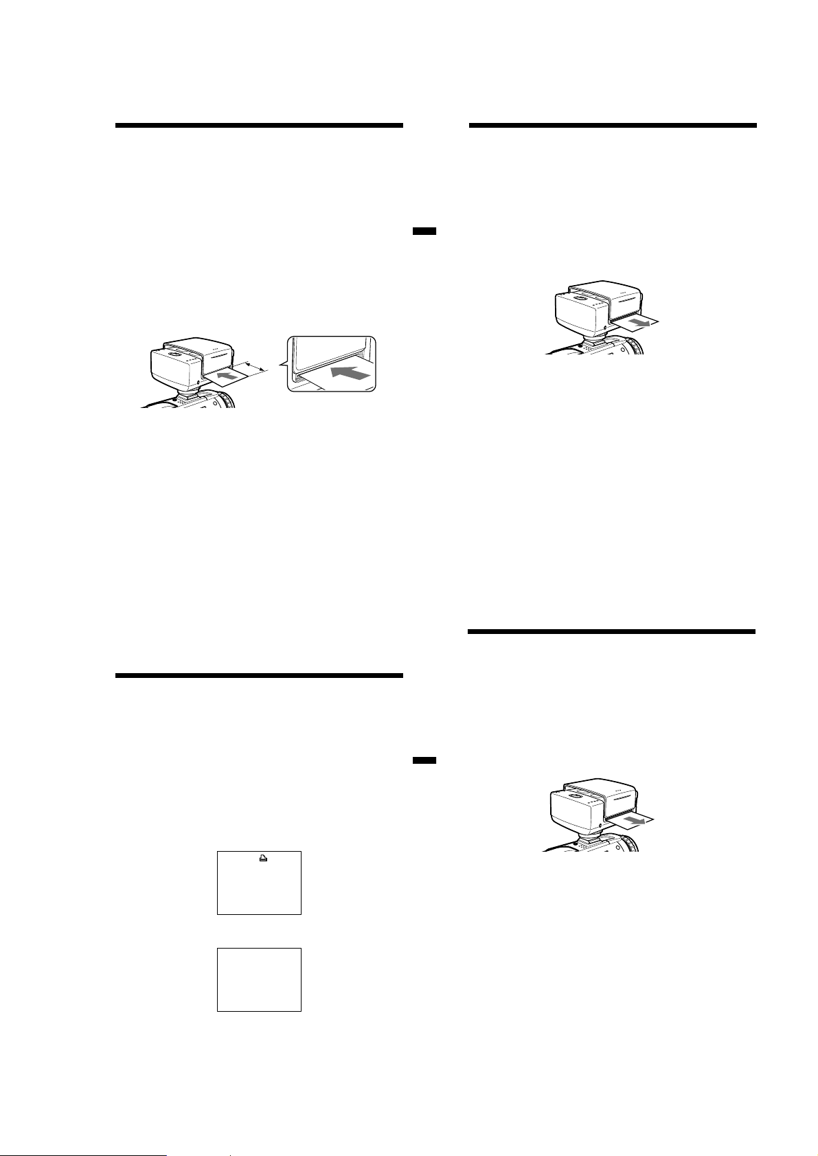
Inserting the print cartridge
Be sure to use the specified print cartridge.
A single new print cartridge allows you to make 20 prints.
1 Slide PRINT CARTRIDGE OPEN knob on the side of this unit in
the direction of the arrow, and open the print cartridge lid.
PRINT CARTRIDGE
OPEN
2 Insert the print cartridge as far as possible in the direction of
the arrow on the cartridge case until it clicks into the cartridge
compartment.
Insert the print cartridge so that the printing head is located between
the ribbon and the cartridge case.
Ribbon protector
(blue cover)
Printing head
Preparation
6-US
Inserting the print cartridge (continued)
3
Close the print cartridge lid completely.
PNote
The inside of this unit sometimes heats up. Do not put your hand inside the
print cartridge compartment.
Removing the print cartridge
Slide the removal switch to the end in the direction of the arrow, and
remove the print cartridge.
The ribbon protector is located between the ribbon and the cartridge
case. This protector prevents the ribbon from being tangled when
inserting the print cartridge into the cartridge compartment.
Insert the print cartridge as it is into the cartridge compartment
without removing the ribbon protector. When the print cartridge is
inserted, the ribbon protector comes loose. Dispose of the ribbon
protector after the print cartridge is inserted.
7-US
Removal switch
8-US
1-1
PNotes
•If the print cartridge is not inserted when the power is turned on, the
CARTRIDGE lamp flashes slowly. The CARTRIDGE lamp flashes fast
when an error occurs on the print cartridge or when the ribbon has run
out.
•If the removal switch is not slid to the end, you may not be able to
remove the print cartridge.
When the print cartridge cannot be inserted easily
Remove the print cartridge, and then re-insert it.
Turn in the direction of the arrow to take up ribbon slack only if ribbon
slack prevents the print cartridge from being inserted correctly.
PNotes
• Do not remove the print cartridge when print paper is inserted. This may
cause this unit to malfunction.
• Do not remove the print cartridge until you use it up. If you reinsert the print
cartridge before you use it up, the possible number of prints per print
cartridge roll may be reduced by one.
Preparation
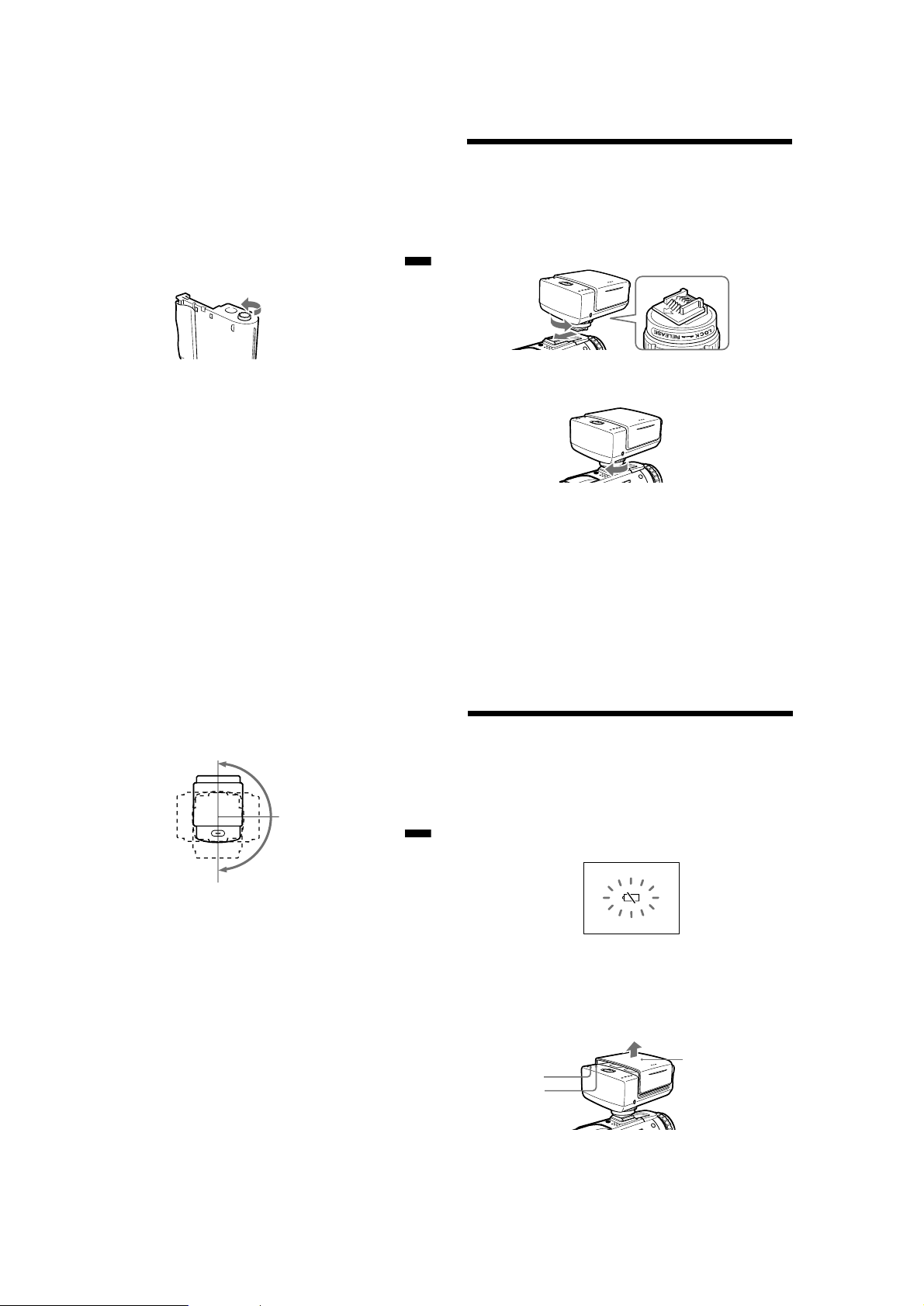
Attaching the printer
Before attaching this unit to your camcorder, make sure that your
camcorder is turned off.
1
Turn the knob in the direction of the arrow (RELEASE) to
loosen. Then, check the direction of the arrow on the shoe
attachment section on this unit, and firmly insert this unit
until it contacts the inside of the accessory shoe.
2
Turn the knob in the direction of the arrow (LOCK), and firmly
tighten until the knob comes to a stop.
PNotes
•If you cannot insert this unit, turn the knob in the direction of the arrow
(RELEASE) to unlock.
•Do not insert this unit backwards. Be sure to insert this unit in the direction of
the arrow.
• Do not lift up your camcorder by this unit.
• Attach this unit to your camcorder firmly. Otherwise, it may become detached
from your camcorder.
9-US
Rotating the printer
This unit rotates toward about 180º in the clockwise direction.
0º
90º
180º
PNote
Do not rotate this unit forcibly more than 180º in the clockwise direction. Doing
so may destroy this unit.
To remove the printer
Turn the knob in the direction of the arrow (RELEASE) to loosen, and then
pull out this unit in the direction opposite to the arrow to remove it.
Preparation
10-US
Preparing the power supply
Be sure to use a fully charged battery, the AC power adaptor or the AC
power adaptor/charger.
Printing is not possible if the battery is low. However, recording may be
possible depending on how much the battery power remains. The
remaining battery time indicator does not indicate the possible printing
time.
If you press PRINT or insert the print paper while the battery is low, the
warning indicator, E, will be displayed on the LCD screen. Replace with a
fully charged battery.
1 Set the POWER switch on your camcorder to MEMORY.
2 Slide the printer cover in the direction of the arrow to open
while holding your camcorder.
The POWER lamp lights, the sound of motor operation stops, and the
PAPER lamp flashes slowly after several seconds.
PAPER lamp
POWER lamp
Printer cover
11-US
1-2
PNote
While recording or playback mode, this unit cannot be turned on.
12-US
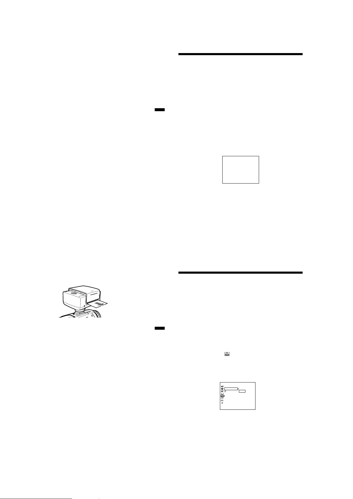
Inserting the print paper
Be sure to use the specified print paper.
The descriptions in this manual are for the DCR-TRV30.
For details on camcorder operation, refer to the operating instructions of
your camcorder.
1
Perform steps1 and 2 on page 12, and prepare the power
supply.
2
Make sure that the PAPER lamp is flashing slowly, and then
insert a sheet of print paper into the paper feeder straight
making sure that the print surface is facing up.
Insert the print paper until less than 3 cm of print paper is protruding
from this unit.
Press the print paper into the paper feeder for about two seconds after
the beep.
The print paper starts to be automatically drawn in.
Less than
3 cm
Preparation
Inserting the print paper
PNotes
• The print paper will not be automatically drawn in unless it is firmly inserted
as far as possible and the print paper is lightly pressed for about two seconds.
• Do not insert print paper from the opposite side of the paper feeder or from
the paper dispenser. Doing so may cause this unit to malfunction.
• Do not insert print paper at an angle. Doing so may cause this unit to
malfunction.
To remove drawn in print paper
Turn off your camcorder once, and then set again to MEMORY. The print
paper is automatically ejected.
Pull out the print paper in the direction of the arrow.
PNote
Do not pull out drawn in print paper forcibly. Doing so may cause this unit to
malfunction.
(continued)
•When the CARTRIDGE lamp is flashing slowly, check the print
cartridge.
•If print paper is not inserted, the PAPER lamp flashes slowly. The
PAPER lamp flashes fast when an error occurs.
PNote
After you have inserted the print paper, do not close the printer cover until
printing ends. Doing so may cause this unit to malfunction.
13-US
BMaking prints - Standard print
You can print images whenever you want to or print images recorded on
“Memory Stick.”
Printing images whenever you want to
Be sure to use a fully charged battery when using the battery to make
prints.
1 Insert the print cartridge and attach this unit to your
camcorder.
2 Set the POWER switch on your camcorder to MEMORY.
3 Open the printer cover, then make sure that the PAPER lamp
is flashing slowly. Insert a sheet of print paper.
4 Keep pressing PRINT lightly until a still image appears.
The CAPTURE indicator appears.
CAPTURE
5 Press PRINT deeper.
PREPARING appears on the LCD screen.
PREPARING
Supplied print paper
Your printer is provided with the following print paper. Select the paper
type to suit your specific requirements:
•Standard type
•Sticker type/Standard size
•Sticker type/9 split size
14-US
Printing images whenever you want to (continued)
6
Printing is started.
The image on the LCD screen disappears.
During printing, the print lamps 1 to 4 light in order, and the print
paper is fed back and forth four times.
When printing ends, the image appears on the LCD screen.
It takes about 160 seconds to make a print.
7
When printing ends, draw out the print paper in the direction
of the arrow.
Making prints - Standard print
PNotes
• The image area of the printed area may differ slightly from the image on your
camcorder or TV.
• The quality of printed images sometimes deteriorates considerably or printing
is not performed if prints are made at a high temperature exceeding the
guaranteed operating temperature range.
• The possible number of prints is sometimes reduced if prints are made at a
low temperature exceeding the guaranteed operating temperature range for
the battery pack.
• The color of printed images sometimes changes slightly depending on the
ambient temperature conditions during printing.
• The possible number of prints is reduced if you use a battery with little
remaining battery power.
While the ribbon is being aligned, the print paper is sometimes
inserted and ejected from the left and right sides of the body without
the LCD screen turning off even if POWER lamp lights.
The image on screen when PRINT is pressed in is printed. This image
is not recorded on “Memory Stick” or tape.
15-US
16-US
1-3
To cancel printing
The print paper is automatically ejected by turning off your camcorder
once, and then setting the POWER switch on your camcorder to MEMORY.
To resume printing, insert new print paper and repeat the procedure from
step 4.
Printing images recorded on “Memory
Stick”
Be sure to use a fully charged battery when using the battery to make
prints.
Insert a recorded “Memory Stick” into your camcorder.
1
Insert the print cartridge and attach this unit to your
camcorder.
2
Making prints - Standard print
Set the POWER switch on your camcorder to MEMORY.
3
Play back the still image you want to print by operating your
camcorder.
4
Open the printer cover, then make sure that the PAPER lamp
is flashing slowly. Insert a piece of print paper.
5
Press PRINT deeper.
PREPARING appears on the LCD screen.
While the ribbon is being aligned, the print paper is sometimes
inserted and ejected from the left and right sides of the body without
the LCD screen turning off even if POWER lamp lights.
6
Printing is started.
The image on the LCD screen disappears.
During printing, priht lamps 1 to 4 light in order, and the print paper
is fed back and forth four times.
When printing ends, the image appears on the LCD screen.
It takes about 160 seconds to make a print.
PREPARING
17-US
7 When printing ends, draw out the print paper in the direction
of the arrow.
Printing the index screen
Display the index screen in step 3.
Printing images recorded on tape
Start from step 3 after capturing the image on “Memory Stick” as a still
image.
* You can also print images superimposed with a still image by the
MEMORY MIX function.
Note, however, that when making split prints, be sure to record the
images first to “Memory Stick” before printing them.
18-US
Printing images with the date
Be sure to use a fully charged battery when using the battery to make
prints.
1 Insert the print cartridge and attach this unit to your
camcorder.
2 Set the POWER switch on your camcorder to MEMORY.
3 Play back the still image you want to print by operating your
Making prints - Standard print
camcorder.
4 Open the printer cover, then make sure that the PAPER lamp
is flashing slowly. Insert the print paper.
5 Select DATE/TIME in in the menu settings of your
camcorder, then press the SEL/PUSH EXEC dial on your
camcorder.
6 Select DATE or DAY & TIME, then press the SEL/PUSH EXEC
dial on your camcorder.
The actual screen may differ from the illustration above.
PR I NT SET
9PIC PRINT
/
TIME
DATE
RETURN DATE
[MENU] : END
OFF
DAY & TIME
19-US
1-4
7 Perform steps 5 to 7 of “Printing images whenever you want
to.”
PNote
The date cannot be entered in 9 - division prints (SAME, MULTI or MARKED)
or index prints.
20-US
BMaking prints of split screens – Split printing
You can print images recorded on “Memory Stick” to print paper (Sticker
type/9 split size).
Printing a single image
Be sure to use a fully charged battery when using the battery to make
prints.
Insert a recorded “Memory Stick” into your camcorder.
1
Insert the print cartridge and attach this unit to your
camcorder.
2
Set the POWER switch on your camcorder to MEMORY.
3
Play back the still image you want to print by operating your
camcorder.
4
Open the printer cover, then make sure that the PAPER lamp
is flashing slowly. Insert the print paper. (Sticker type/9 split
size).
5
Select 9PIC PRINT in in the menu settings of your
camcorder, then press the SEL/PUSH EXEC dial on your
camcorder.
6
Select SAME, then press the SEL/PUSH EXEC dial on your
camcorder.
The actual screen may differ from the illustration above.
7
Perform steps 5 to 7 of “Printing images whenever you want
to.”
PNotes
• You cannot print the display on the LCD screen.
• The following images cannot be propely devided:
– Index screen
– Multi screen
• You cannot print moving pictures.
PR I NT SET
9PIC PRINT RETURN
SAME
DATE/TIME
RETURN MULTI
MARKED
[MENU] : END
21-US
Printing images recorded on “Memory
Stick” in recording order
Be sure to use a fully charged battery when using the battery to make prints.
Insert a recorded “Memory Stick” into your camcorder.
1
Insert the print cartridge and attach this unit to your
camcorder.
2
Set the POWER switch on your camcorder to MEMORY.
3
Play back the still image you want to print by operating your
camcorder.
4
Open the printer cover, then make sure that the PAPER lamp
is flashing slowly. Insert the print paper. (Sticker type/9 split
Making prints of split screens – Split printing
size)
5
Select 9PIC PRINT in in the menu settings of your
camcorder, then press the SEL/PUSH EXEC dial on your
camcorder.
6
Select MULTI, then press the SEL/PUSH EXEC dial on your
camcorder.
The actual screen may differ from the illustration above.
Nine still images are displayed divided in order from the playback
screen selected in step 3.
If the number of still images is less than nine, all of the images up to
the last image are displayed.
In MULTI mode, you cannot select respective images you want to
print or change the order of images to print out.
7
Perform steps 5 to 7 of “Printing images whenever you want
to.”
PNotes
• You cannot print the display on the LCD screen.
• The following images cannot be propely devided:
– Index screen
– Multi screen
• You cannot print moving pictures.
PR I NT SET
9PIC PRINT RETURN
DATE/TIME
RETURN MULTI
[MENU] : END
22-US
SAME
MARKED
Printing images with print marks
Be sure to use a fully charged battery when using the battery to make prints.
Refer to the operating instructions of your camcorder to output print
marks on still images.
Insert a recorded “Memory Stick” into your camcorder.
1 Insert the print cartridge and attach this unit to your
camcorder.
2 Set the POWER switch on your camcorder to MEMORY.
3 Play back the still image with PRINT MARK by operating your
camcorder.
4 Open the printer cover, then make sure that the PAPER lamp
is flashing slowly. Insert the print paper. (Sticker type/9 split
size)
5 Select 9PIC PRINT in in the menu settings of your
camcorder, then press the SEL/PUSH EXEC dial on your
camcorder.
6 Select MARKED, then press the SEL/PUSH EXEC dial on your
camcorder.
The actual screen may differ from the illustration above.
Still images marked with PRINT MARK are displayed divided in
order.
7 Perform steps 5 to 7 of “Printing images whenever you want
to.”
PNotes
• You cannot print the display on the LCD screen.
• The following images cannot be propely devided:
– Index screen
– Multi screen
• You cannot print moving pictures.
PR I NT SET
9PIC PRINT RETURN
SAME
DATE/TIME
RETURN MULTI
MARKED
[MENU] : END
BAdditional Information
Precautions
About this printer
•This printer can be used only on printer-compatible camcorders.
•Attach this unit to your camcorder making sure that your camcorder is
turned off. Otherwise this unit may operate incorrectly.
•Never close the printer cover during printing. Doing so may cause a
paper jam or other trouble.
•If you disconnect the power source such as the battery pack during
printing, the platen roller may not move back to the original position.
Install the charged battery pack, and perform the operation again.
•During printing, the print paper is inserted and ejected in the paper
Making prints of split screens – Split printing
dispenser. Do not place any objects that may prevent the print paper
from being inserted and ejected from the body.
•Only the power switch on your camcorder can be operated while print
paper is being fed into or out of the body. Other operations are not
possible. You can operate your camcorder after the print paper has
stopped being fed.
•During printing, do not draw out the print paper. Doing so might cause
this unit to malfunction.
•During printing, do not touch the print surface.
•During printing, do not subject the body to vibration or shock.
•We recommend making repeat prints from images stored on “Memory
Stick.” Repeat prints cannot be made of the same screen if it is not
recorded on “Memory Stick.”
•Printing images recorded continuously, multi screen, is not possible. To
print those images, store them on “Memory Stick” in advance.
•You cannot operate this unit while SLIDE SHOW is executed on your
camcorder.
About the print cartridge
•Do not touch the ribbon or leave it in a dusty place.
Fingerprints or dust on the ribbon sometimes prevent good-looking
prints from being made.
•Avoid storing the print cartridge in high temperature or humid locations,
dusty locations or direct sunlight.
23-US
24-US
1-5

About print paper
•Lines or small squares are printed on the reverse side of print paper. Use
the side with nothing printed as the print surface.
•Use only the specified print paper. Use of other paper may cause this
unit to malfunction.
•Before you start printing, do not write on the print paper or print on the
print paper on a word processor.
When writing on the print surface of print paper after printing, use an
oil-based pen. Printing on the print surface is not possible on a word
processor.
•When handling print paper, do not touch the print surface.
•Do not load sticker print paper whose seals have been peeled off. Doing
so might cause paper jams.
•Do not fold or bend print paper. Doing so might cause paper jams.
•Do not leave print paper in dusty locations. Fingerprints or dust on the
ribbon sometimes prevent good-looking prints from being made.
•Store print paper in the bag which it first came in.
•Avoid storing print paper in high temperature or humid locations, dusty
locations or direct sunlight.
If you use up the supplied print paper and print cartridge
Purchase the specified color print pack, CPPM-NR40 (Standard type) or
CPPM-SC40 (Sticker type), for this unit.
25-US
Troubleshooting
If you run into any problem using this unit, use the following table to
troubleshoot the problem. If the problem persists, disconnect the power
source and contact your Sony dealer or local authorized Sony service
facility.
Symptom Cause and/or Corrective Actions
Print paper cannnot be
drawn in the paper feeder.
Additional Information
Images do not become still
images even you press
PRINT.
26-US
•The printer is not attached correctly.
t Attach it correctly.
•The battery power is low.
t Use the battery pack charged fully.
•The print cartridge is not inserted.
t Insert the print cartridge.
•You have inserted print paper into the
paper feeder right after you turned the
power source on or right after you
opened the printer cover.
t Remove the print paper once.
Make sure that the PAPER lamp is
flashing slowly, and then insert print
paper into the paper feeder.
•The POWER switch on your camcorder is
not set to MEMORY.
t Set it to MEMORY.
•The print paper is not inserted properly.
t Press the print paper into the paper
feeder for about two seconds after the
beep sounds.
•Printing images continuously makes the
inside of the printer heat up. When this
happens, you may not be able to insert
print paper.
t Leave this unit until it cools down,
then insert print paper into the paper
feeder again.
•SLIDE SHOW is executed on your
camcorder.
t Cancel SLIDE SHOW or inset the
print paper again after SLIDE SHOW
has completed.
•Print paper or the print cartridge is not
inserted.
t Insert the print paper or the print
cartridge.
Symptom Cause and/or Corrective Actions
When you print images
recorded on the “Memory
Stick”, printing does not
start even you press
PRINT.
The print cartridge cannot
be removed from the
cartridge compartment.
You cannot insert the
print cartridge.
•You have pressed PRINT lightly.
tPress PRINT deeper.
•Print paper is inserted.
t Remove the print paper.
•Printing is executed.
t Remove the print cartridge after the
printing is completed.
•Removal switch is not slid to the end.
t Slide it to the end.
•The ribbon is jammed in the cartridge
compartment.
t Contact your Sony dealer or local
authorized Sony service facility.
•If you disconnect the power source such
as the battery pack during printing, the
platen roller may not move back to the
original position.
t Install the charged battery pack, set
the POWER switch on your
camcorder to MEMORY and open
the LCD panel and the printer cover.
•If you disconnect the power source such
as the battery pack during printing, the
platen roller may not move back to the
original position.
t Install the charged battery pack, set
the POWER switch on your
camcorder to MEMORY and open
the LCD panel and the printer cover.
(Continued on the following page)
Troubleshooting (continued)
Symptom Cause and/or Corrective Actions
The print lamps 3 and 4
are flashing fast.
The CARTRIDGE lamp is
flashing fast.
Additional Information
Printing stops midway,
and the PAPER lamp is
flashing fast.
You cannot select SAME,
MULTI or MARKED in
the menu settings on your
camcorder.
The printed image has a
black frame.
You cannot remove print
paper.
•The inside of the printer has become too
hot.
t Leave this unit until it cools down,
then resume printing images.
•The ribbon has run out.
t Replace the print cartridge with a
new one.
•You have left the printer cartridge in
high temperature so that the ribbon is
damaged.
t Replace the print cartridge with a
new one.
•An error has occured during printing.
t Turn off your camcorder once, and
then set it to MEMORY again.
t Charge the battery, and reinstall it.
•Print paper is not inserted, and the still
image to print is not played back.
t Insert print paper, and play back the
still image to print.
•A frame sometimes appears when you
use this unit on a camcorder other than
the one you used for recording images
to “Memory Stick.” This is not a
malfunction.
•Print paper is jammed.
t Contact your Sony dealer or local
authorized Sony facility.
27-US
28-US
1-6

Maintenance information
About the influence of dirt on the printer
Printed images may have red, blue, or white dots or thin lines on their
surface due dirt or dust entering the printer. This is not a malfunction.
These symptoms may become worse depending on the storage conditions
of the print paper or print cartridge.
See “Precautions” for details when handling print paper and the print
cartridge.
About cleaning printer heads
We recommend that you clean the printer heads with the head cleaner
(supplied) when you exchange the print cartridge. If printed images have
thin lines, remove the print cartridge, and clean the heads. Handle the
print cartridge with care. See “Inserting the print cartridge” for details
when inserting the print cartridge.
Maintenance information (continued)
About the color of printed images
Printing images continuously or printing images at a high temperature
may cause the color of the printed images to change.
About the influence of dirt on the platen roller
Printed images may have red, blue, or white dots periodically in horizontal
direction due dirt or dust on the platen roller which is inside of the printer.
If this happens, clean the platen roller with the platen roller cleaner.
Additional Information
How to clean the platen roller
Perform steps 1 to 7 of “Printing images whenever you want to.” Note
that insert the platen roller cleaner instead of print paper in step 3 making
sure that the surface of the platen roller cleaner is facing up.
How to clean the printer heads
Insert and remove the head cleaner several times to clean the printer head.
Store the head cleaner in the specified case (supplied) after cleaning the
printer head.
29-US
PNotes
• If you insert the platen roller cleaner in the wrong direction, it will not be
drawn in the paper feeder.
• Insert the platen roller cleaner vertically against the body. Inserting
inappropriately causes a malfunction.
• You can clean the platen roller 3 times per platen roller cleaner. You cannot
use it more than 3 times.
• Because cleaning the platen roller can be done by printing an image on the
platen roller cleaner, the printed image may not be clear. This is not a
malfunction.
• The number of printed image per print cartridge roll will be reduced by one
after cleaning the platen roller.
On purchasing cleaners
Contact your Sony dealer or local authorized Sony service facility and
inform them of the following product numbers:
•Head cleaner (1-772-863-11)
•Platen roller cleaner (1-772-862-11)
Cleaner part
Front side Back side
Less than 3 cm
Store the platen roller cleaner in the bag which it first came in.
30-US
Additional Information
31-US
1-7E

SECTION 2
6
Cabinet (upper)
assembly
1
Three screws
(M2
×
3)
1
Four protrusions
3
T wo protrusions
4
Three claws
2
Paper gate cover
assembly
5
Ribbon lid
assembly
5
Ribbon lid
8
Ribbon lid fixed
plate assembly
2
ALP guide
7
R knob
3
4
6
DISASSEMBLY
NOTE: F ollo w the disassembly procedure in the numerical order given.
2-1. PRINTER UNIT SECTION
7
Remove the cabinet (upper) section in the
direction of arrow B while taking care of
protruded portion inside the cabinet upper.
1
Screw (M2 × 5),
lock ace, p2
3
Two screws (M2 × 5),
lock ace, p2
B
2
Screw (M2 × 5),
lock ace, p2
Protruded portion
of static electricity
eliminator.
PRECAUTION DURING CABINET (UPPER)
SECTION INSTALLATION
Note: First place the protection sheet for assembling on top of the printer
unit in order to protect the protruded portion inside the cabinet
(upper) and the protruded portion of static electricity eliminator,
from being damaged. Upon completion of reassembling, remove
the protection sheet for assembling in the direction of the arrow.
Printer unit
section
PVP-MSH
Protruded portion inside
the cabinet (upper) section.
2
Cabinet (upper)
section
Protruded portion of
static electricity eliminator.
8
Printer unit
5
Harness
(HP-138)
(15P)
4
Remove the cabinet (lower) section in the
direction of the arrow A.
(included in shoe hot)
section
6
Screw (M2 × 5),
lock ace, p2
A
2-2. CABINET (UPPER) SECTION
1
Protection sheet
for assembling
3
Remove the protection
sheet for assembling.
2-1
 Loading...