

Sony PMW-RX50 Operating Instructions Manual

Portable Memory
Recorder
4-547-852-11 (1)
Operating Instructions
Before operating the unit, please read this manual thoroughly
and retain it for future reference.
PMW-RX50
© 2014 Sony Corporation

Table of Contents
Overview
Preparations
Part Identification ..................................................................... 5
Front View ..................................................................... 5
Rear View ....................................................................... 6
Top Panel ....................................................................... 6
Audio Input Box (Supplied) ........................................... 7
IR Remote Commander (Supplied) ................................ 7
On-Screen Indications .................................................... 9
Software Downloads ............................................................... 10
Power Supply ........................................................................... 11
Using a Battery Pack .................................................... 11
Using AC Power (DC IN Power) ................................. 12
Turning the Power On/Off ........................................... 12
Setting the Clock ..................................................................... 12
Using SxS Memory Cards ...................................................... 13
Using Other Media .................................................................. 15
Removing and Attaching the Audio Input Box .................... 16
Removing the Audio Input Box ................................... 16
Attaching the Audio Input Box .................................... 16
Using a Wi-Fi Connection ...................................................... 17
Attaching the CBK-WA100 ......................................... 17
Connecting to Wi-Fi with the CBK-WA100 ............... 18
Using the Web Menu ................................................... 18
Using Wi-Fi Remote Control ....................................... 19
Recording
Table of Contents
2
Changing Basic Settings ......................................................... 21
Selecting an Input Signal ............................................. 21
Video Formats .............................................................. 21
Time Data ..................................................................... 23
Setting the Output Mode .............................................. 23
Recording ................................................................................. 24
Useful Functions ...................................................................... 25
Color Bars/Reference Tone .......................................... 25
Playback
exFAT FAT/HD
Shot Marks ............................... 25
OK/NG/KP Flags ................................... 25
OK Mark ........................................................ 25
Assignable Buttons ....................................................... 26
Clip Continuous Recording .................... 26
Loop Recording ...................................... 27
Deleting Clips ............................................................... 27
Storing/Retrieving the Setting Data ............................. 28
Planning Metadata ........................................................ 28
Thumbnail Screens ................................................................. 32
Configuration of the Thumbnail Screen ....................... 32
Changing the Type of Thumbnail Screen .................... 33
Playing Clips ............................................................................ 34
Playing the Selected and Subsequent Clips in
Sequence ................................................................ 34
Playing between In-point and Out-point ...................... 34
Playing Clips in Repeat Mode ...................................... 35
Monitoring Audio ......................................................... 35
Cueing Up .................................................................... 35
Clip Operations ....................................................................... 36
Clip Operation Menus .................................................. 36
Basic Operations of the Clip Operation Menus ........... 36
Displaying the Detailed Information of a Clip ............. 38
OK/NG/KP Flag ..................................... 38
OK Mark ........................................................ 39
Copying Clips ............................................................... 39
Deleting Clips ............................................................... 39
EXPAND CLIP Screen ................................................ 39
SHOT MARK Screen .............. 41
Changing the Index Frame ...... 42
Dividing a Clip .............................................. 42
UDF
UDF exFAT
FAT/HD
UDF exFAT
UDF exFAT
UDF exFAT
FAT/HD
UDF exFAT FAT/HD
UDF exFAT FAT/HD
FAT/HD
Status Displays
Showing the Status Screens .................................................... 43
Audio Status Screen ..................................................... 43
Video Status Screen ..................................................... 43
Button/Remote Status Screen ....................................... 44
Battery/Media Status Screen ........................................ 44
Table of Contents
3

Menu Configuration and Detailed Settings
Overview of the Setup Menus ................................................ 45
Setup Menu Layers ...................................................... 45
Basic Menu Operations .......................................................... 46
Setup Menu List ...................................................................... 47
[AUDIO SET] Menu .................................................... 47
[VIDEO SET] Menu .................................................... 49
[LCD SET] Menu ......................................................... 52
[TC/UB] SET Menu ..................................................... 53
[OTHERS] Menu ......................................................... 54
Connecting External Devices
Connecting External Monitors and Camcorders ................. 65
Connecting Audio Equipment ............................................... 66
Connecting a Computer ......................................................... 67
Connecting via i.LINK ........................................................... 68
Recording the Image on an External Device ...... 68
Nonlinear Editing ................................................ 68
Recording and SDI Output of External Input
Signals .................................................................... 69
Connecting USB Media .......................................................... 70
Supported USB Media ................................................. 70
Copying Clips ............................................................... 70
Displaying the USB Media Thumbnail Screen ............ 70
FAT
FAT
Appendices
Table of Contents
4
Important Notes on Operation .............................................. 72
Recording Video Formats ([Rec Format]) ............................ 74
Formats and Limitations of Outputs .................................... 76
Backup Battery Replacement ................................................ 83
Troubleshooting ...................................................................... 84
Licenses .................................................................................... 88
MPEG-4 AVC Patent Portfolio License ...................... 88
MPEG-2 Video Patent Portfolio License ..................... 88
Bitmap Fonts ................................................................ 88
On accessing software to which the GPL applies ........ 88
About OpenSSL ........................................................... 88
About JQuery,Sizzle.js ........................................................... 91
Specifications ........................................................................... 91
Overview
Part Identification
For functions and usage, see the pages in parentheses.
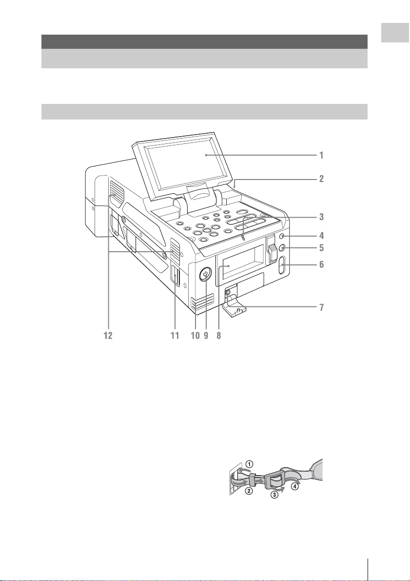
Front View
Overview
The above is an illustration with the audio input box removed. For details on the parts of the audio input box,
see “Audio Input Box (Supplied)” (page 7).
1. LCD monitor
The LCD monitor LCD can be rotated 180° in
the clockwise direction and 90° in the
counterclockwise direction when it is open. It
can also be stowed on the top surface of the
recorder with the screen facing up.
To rotate the LCD monitor, tilt it toward you
(approximately 80°) and then turn it sideways.
8. Memory card slots (page 13)
9. Power button/lamp (page 12)
10. Built-in speaker
11. Shoulder strap mounting points
The supplied shoulder straps mount as shown in
the following diagram.
2. Exhaust vent
Do not block the exhaust vent.
3. TALLY lamp
4. Infrared light receiver sensor
5. SLOT SELECT button
12. Intake vent
Do not block the intake vent.
6. VOLUME buttons
7. Headphone connector
Part Identification
5
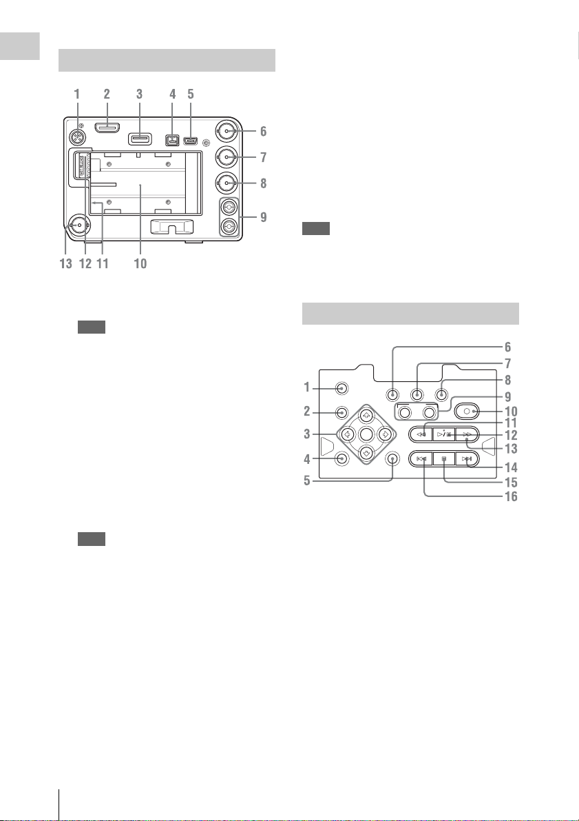
Rear View
Overview
1. DC OUT connector (4-pin) (for CBK-
WA100) (page 18)
Note
When operating on battery power, the voltage
output will be that of the battery.
2. HDMI OUT connector (page 65)
3. External device connector
Connect a CBK-WA100 Wireless Adapter (not
supplied), an IFU-WLM3 USB Wireless LAN
Module (not supplied), or a USB flash drive
here.
When a CBK-WA100/IFU-WLM3 is
connected: You can connect the recorder to a
computer via a Wi-Fi (wireless) connection.
When a USB flash drive is connected: You can
record, save, and load the following data.
• Planning metadata (page 28)
Note
Use this connector only for the CBK-WA100, IFUWLM3, USB flash drives, and USB media. Do not
connect and use USB hubs and other devices.
For details on Wi-Fi connections, see “Using a
Wi-Fi Connection” (page 17).
4. i.LINK (HDV/DV) connector (4-pin,
IEEE1394 S400-compliant) (page 65)
5. PC connector
Switch the recorder to USB connection mode,
and use this connector to use the unit as an
external memory device of a computer.
6. SDI IN (serial digital input) connector
(BNC type) (page 65)
7. SDI OUT 1 (serial digital output)
connector (BNC type) (page 65)
8. VIDEO OUT (analog video output)
connector (BNC type) (page 65)
9. AUDIO OUT (analog audio output)
connector (CH-1/CH-2) (page 65)
10. Battery pack receptacle (page 11)
11. DC IN (DC power supply input) connector
(page 12)
12. BATT RELEASE (battery release) button
(page 11)
13. SDI OUT 2 (serial digital output)
connector
Note
Power can only be supplied to an external device from
either the DC OUT connector or the external device
connector. They cannot both be used to supply power at
the same time.
Top Panel
DURATION
TC/U-BIT
THUMBNAIL
MENU CANCEL
1. DURATION/TC/U-BIT (time data
selection) button (page 23)
2. THUMBNAIL (thumbnail display) button
(page 32)
3. Up/Down/Left/Right buttons, SEL/SET
(select/set) button (page 46)
Press the left/right buttons during playback/
pause to play in slow motion.
4. MENU (menu display ON/OFF) button
(page 46)
5. CANCEL button (page 46)
6. STATUS (status display selection) button
(page 43)
This can also be used as the ASSIGN 3
(assignable) button (page 26).
STATUS LCD BRIGHT DISPLAY
SEL
SET
ASSIGN
F REV F FWDPLAY/PAUS E
PREV
21
STOP/EE
REC
NEXT
Part Identification
6
7. LCD BRIGHT (LCD monitor brightness
adjustment) button
This can also be used as the ASSIGN 4
(assignable) button (page 26).
8. DISPLAY button (page 9)
This can also be used as the ASSIGN 5
(assignable) button (page 26).
9. ASSIGN 1/2 (assignable) buttons (page 26)
10. REC (record) button (page 24)
11. F REV (fast reverse playback) button
(page 35)
12. PLAY/PAUSE button (page 34)
13. F FWD (fast forward playback) button
(page 35)
14. NEXT (next clip) button (page 35)
15. STOP/EE (button) (pages 24 and 32)
16. PREV (previous clip) button (page 35)
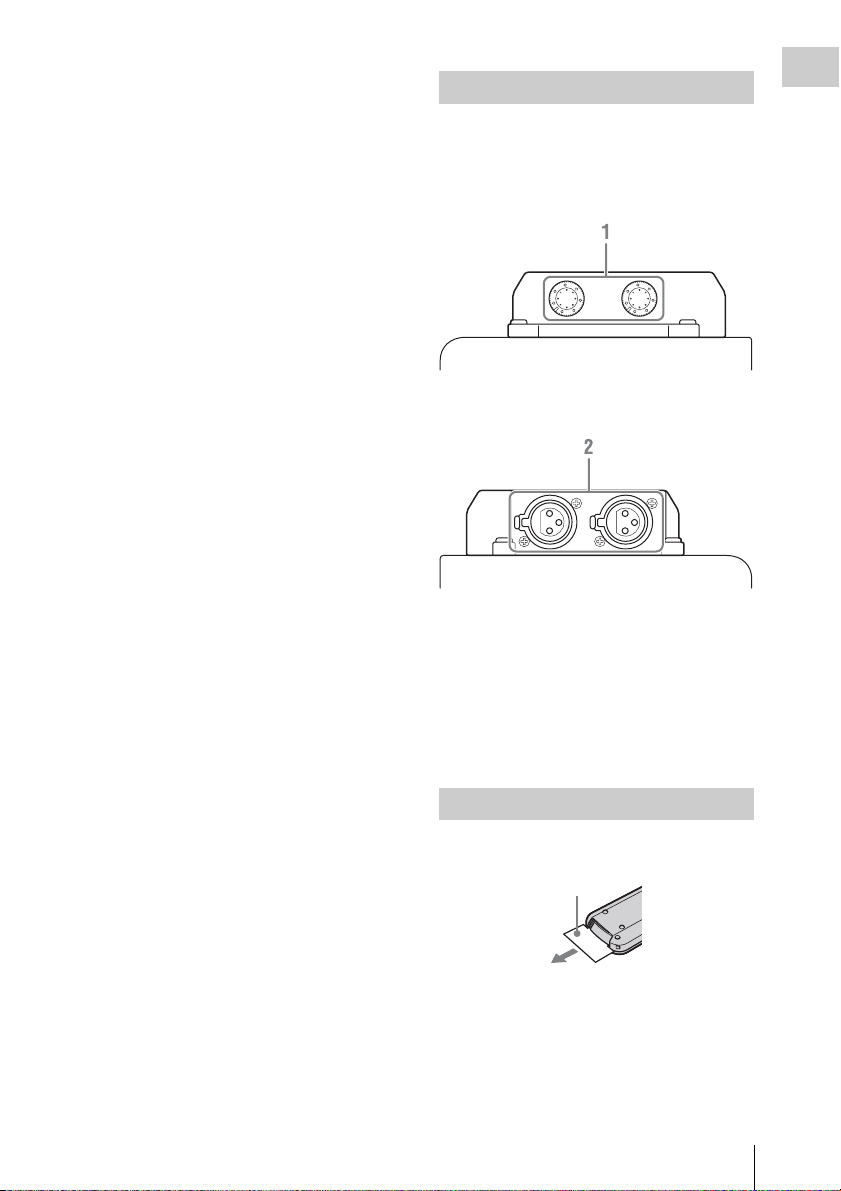
Audio Input Box (Supplied)
The audio input box is removable. For details, see
“Removing and Attaching the Audio Input Box”
(page 16).
Front
Rear
1. AUDIO LEVEL CH-1/CH-2 adjustment
knobs (page 66)
2. AUDIO IN CH-1/CH-2 connectors (page
66)
To input audio signals to the AUDIO IN connectors,
[Audio Input] (page 47) must be configured in the
[AUDIO SET] menu.
Overview
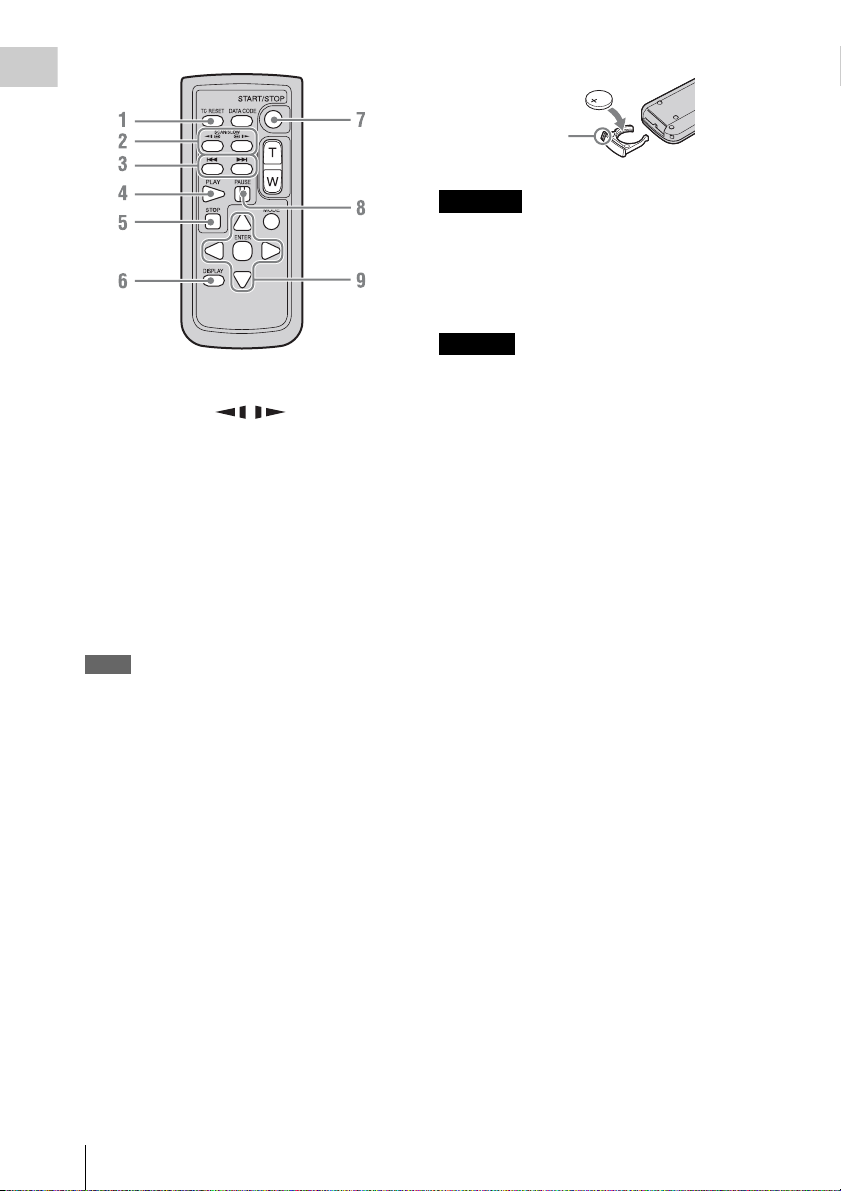
IR Remote Commander (Supplied)
Before use, pull out the insulation sheet.
Insulation sheet
Part Identification
7
Overview
1. TC RESET (timecode reset) button
2. SCAN/SLOW (fast reverse
playback / fast playback) buttons
3. . > (previous/next clip) buttons
4. PLAY button
5. STOP button
6. DISPLAY (screen display) button
7. START/STOP (recording start/stop)
button
8. PAUSE button
9. b/B/v/V/ENTER buttons
Notes
• The DATA CODE, T/W (zoom), and MODE buttons
are not used with this recorder.
• To avoid malfunctions, the remote control function is
automatically deactivated when the recorder is turned
off. Activate the function each time when required
after you turn the recorder on.
Replacing the battery in the IR Remote
Commander
Use a commercially available CR2025 lithium
battery. Do not use any battery other than a
CR2025.
Tab
WARNING
• Battery may explode if mistreated.
Do not recharge, disassemble, or dispose of in
fire.
• Batteries shall not be exposed to excessive heat
such as sunshine, fire or the like.
CAUTION
Danger of explosion if battery is incorrectly
replaced. Replace only with the same or
equivalent type recommended by the
manufacturer.
When you dispose of the battery, you must obey
the law in the relative area or country.
1 Press the tab inward and grasp it with
your fingernail to pull out the battery
case.
2 Insert the new battery with its + side
facing up.
3 Insert the battery case until it clicks into
place.
Part Identification
8
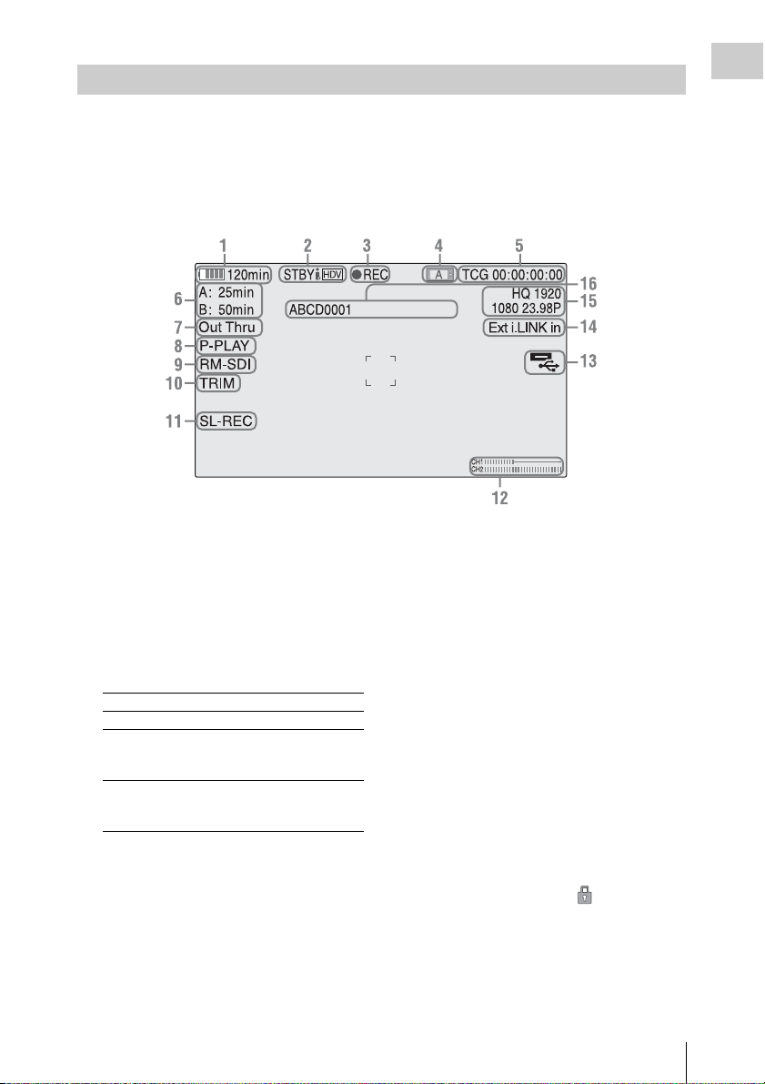
On-Screen Indications
While recording or in standby mode, pressing the DISPLAY button displays the status and settings of this
unit on the LCD monitor.
Remarks
[M]: The indication of the items named with this suffix can be independently turned on/off with [Display
On/Off] in the [LCD SET] menu (page 52).
Overview
1. Battery remaining/DC IN voltage
indication [M] (page 11)
2. i.LINK status indication (page 68)
Only when an external device is connected to
the i.LINK connector, the status of the device is
displayed.
3. Special recording/operation status
indication
zREC Recording in progress
STBY Standby for recording
CONT (lit) When using Clip Continuous
CONT
(flashing)
Recording, indicates that a
clip is being continued.
When using Clip Continuous
Recording, indicates there is
no continuing clip.
4. Media status indication
Displays the active memory card slots.
5. Time data indication [M] (page 23)
6. Media remaining indication [M] (page 14)
7. Output mode indication (page 23)
Displays “Out Thru” when the output mode is
set to [THROUGH], or [Out Auto] when the
output mode is set to [AUTO].
8. In-point to out-point partial playback
indication (page 34)
Displays “P-PLAY” when playing the interval
from the in-point to the out-point.
9. Synchronous recording indication [M]
Displays “RM-SDI” when [SDI Rec Control]
in the [VIDEO SET] menu is set to [On].
Displays “Rec2” when the REC trigger
signal is output when using the
CBK-WA100.
10. Trim indication (page 35)
11. Loop recording indication (page 27)
Displayed when loop recording.
12. Audio level meters [M]
13. USB media icon indication (page 70) or
wireless adapter status indication
Displays an icon when valid USB media (HDD,
flash drive, or other USB device) is connected.
If the media is protected, a lock mark
appears.
If a CBK-WA100 wireless adapter is connected,
it displays the wireless status, SD card
remaining capacity, and clip transfer status.
Part Identification
9

14. Input signal indication
Overview
Displayed when a signal is input from the input
source selected by [Input Source Select] in the
[VIDEO SET] menu.
Ext SDI in Input from the SDI IN
Ext i.LINK in HDV/DVCAM input from the
SG Color bar output
Note
If the indication is blinking, check whether [REC
Format] matches the input signal and whether the
input signal is distorted.
connector
i.LINK connector
15. Video Format indication [M] (page 21)
16. Clip name indication [M] (page 24)
Software Downloads
When the unit is used with a PC connection,
download any device drivers, plug-ins, and
application software you require from the
following websites.
Sony Professional products website:
U.S.A. http://pro.sony.com
Canada http://www.sonybiz.ca
Latin America http://sonypro-latin.com
Europe, http://www.pro.sony.eu/pro
Middle East, Africa http://sony-psmea.com
Russia http://sony.ru/pro/
Brazil http://sonypro.com.br
Australia http://pro.sony.com.au
New Zealand http://pro.sony.co.nz
Japan http://www.sonybsc.com
Asia Pacific http://pro.sony-asia.com
Korea http://bp.sony.co.kr
China http://pro.sony.com.cn
India http://pro.sony.co.in
Sony Creative Software, software download
page:
http://www.sonycreativesoftware.com/
download/software_for_sony_equipment
Software Downloads
10
Preparations
Power Supply
You can use a battery pack or AC power via an
AC adaptor.
For safety, use only the Sony battery packs and
AC adaptor listed below:
Lithium-ion Battery Pack
BP-U30/BP-U60/BP-U90
Battery Charger/AC Adaptor
BC-U1/BC-U2
WARNING
Batteries shall not be exposed to excessive heat
such as sunshine, fire or the like.
Note
The AC adaptor cannot be connected to the recorder
while the battery pack is inserted.
Using a Battery Pack
Fully insert the battery pack into the battery pack
receptacle (page 6), then slide it to the right to
lock it.
To remove the battery pack, press and hold the
BATT RELEASE button (page 6), slide the
battery pack to the left to unlock it, then pull it
out.
Notes
• Before use, charge the battery pack with the supplied
BC-U1 or BC-U2 Battery Charger.
• A warm battery pack immediately after use may not be
able to be fully recharged.
• The high-capacity BP-U90 Battery Pack is large, and
protrudes from the recorder when attached.
Checking battery charge remaining
When recording or playback is in progress on the
battery pack, an icon to show the current battery
charge level and usage time remaining are
displayed on the LCD monitor (page 9).
Icon Remaining
100% to 91%
90% to 71%
70% to 51%
50% to 31%
30% to 11%
10% to 0%
The recorder indicates the remaining usage time
in minutes if operation is continued at the current
rate of power consumption.
If the battery charge remaining becomes
low
If the battery charge remaining decreases to a
certain level during operation (Low BATT
status), a low-battery message, flashing of the
tally lamps, and a beep sound will warn you.
If the remaining further decreases to a level at
which operation cannot be continued (BATT
Empty status), a battery-empty message appears.
Replace the battery pack with one that is fully
charged.
To change the message levels
The “Low BATT” level is set to 10% of full
charge, and the “BATT Empty” level is set to 3%
of full charge at the factory. These settings can be
changed with [Battery Alarm] (page 57) in the
[OTHERS] menu.
Preparations
Power Supply
11
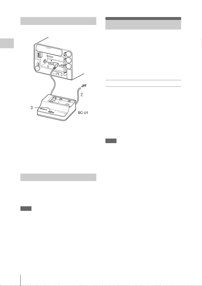
Using AC Power (DC IN Power)
Connection example: when connecting BC-U1
Preparations
D
C
O
U
T
C
H
A
R
G
E
0
%
8
B
0
A
T
T
E
B
R
10
C
Y
0
U
C
1
H
A
RG
E
R
1 Connect the DC power output cable of
the BC-U1 to the DC IN connector of
the recorder.
2 Connect the p ower cord of the BC-U1 to
an AC power source.
3 Set the mode switch of the BC-U1 to the
DC OUT position.
Turning the Power On/Off
Setting the Clock
When you turn the recorder on for the first time
after purchasing or replacing the backup battery
(page 83), the Initial Setting display appears on
the LCD monitor.
Time Zone
The value shows the time difference from UTC
(Coordinated Universal Time).
Change the setting if needed.
Setting the time and date
Move the cursor, then press the SEL/SET button
to set each menu item. When you press the SEL/
SET button when the cursor is on [Finish], the
Initial Setting display disappears, and the clock
setting is completed.
After the Initial Setting display disappears, [Time
Zone] (page 55) and [Clock Set] (page 55) in the
[OTHERS] menu can be used to set [Time Zone]
and [Date/Time].
Notes
• If the clock setting is cleared because of exhaustion of
the backup battery while no operation power was being
supplied (no battery pack and no DC IN connection),
the Initial Setting display will be displayed when you
turn the recorder on at the next opportunity.
• While the Initial Setting display is shown, no other
operation except turning the power off is permitted
until you finish the setting for this display.
To turn on the power supply, press the power
button (page 5). The power supply lamp lights up.
To turn off the power supply, press the power
button again.
Notes
• This recorder uses a litt le standby power even when the
power button is set to OFF. Remove the battery pack if
the recorder will not be used for a prolonged period.
• When removing the battery pack or the DC IN power,
be sure to first set the power button to the OFF
position. Removing the battery pack or the DC IN
power while the recorder is ON may cause damage to
the recorder or the SxS memory card.
Setting the Clock
12
Using SxS Memory Cards
Insert SxS memory cards (not supplied) (herein
referred to as memory cards) into the card slots to
record video and audio.
For details on other types of media you can use with
the recorder, see “Using Other Media” (page 15).
Supported SxS memory cards
Use the following Sony-made memory cards.
For details on operations with media from other
manufacturers, refer to the operating instructions
for the media or consult the manufacturer’s
information.
SxS PRO+ series
SxS PRO series
SxS-1 series
SxS PRO and SxS-1 series cards comply with the
ExpressCard standard.
Inserting a memory card
1 Open the cover of the card slot block.
2 Insert the memory card in the card slot
with the label facing up, and close the
cover.
Cover open
Status indications by the ACCESS lamps
Lamp Slot statuses
Lights red Accessing the loaded memory card
Lights
green
Off • No memory card is loaded.
(writing/reading data)
Standby (ready for recording or
playback using the loaded memory card)
• The loaded card is invalid.
• A memory card in another slot is
active.
Removing a memory card
1 Open the cover of the card slot block,
press the EJECT button, then pull the
button out.
2 Press the EJECT button again to
remove the card.
Note
Data are not guaranteed if the power is turned off or a
memory card is removed while the card is being
accessed. All data on the card may be destroyed. Be sure
that the ACCESS lamps are lit in green or off when you
turn off the power or remove memory cards.
Switching between memory cards
Press the SLOT SELECT button (page 5).
If a card becomes fu ll during recording, switching
to the other card is automatically executed.
Note
The SLOT SELECT button is disabled while playback is
in progress. Switching is not executed even if you press
the button. The button is enabled while the thumbnail
screen is displayed (page 32).
Preparations
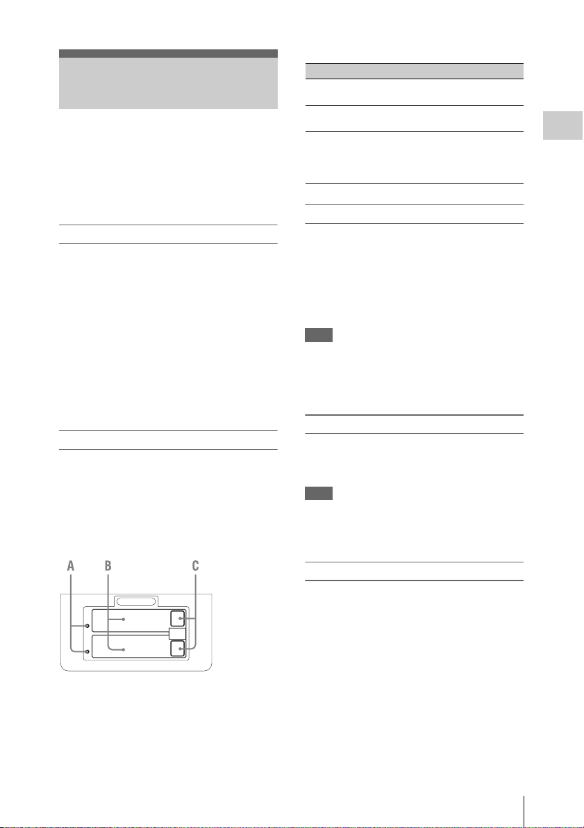
A
B
A. ACCESS lamps
B. SxS memory card slots
C. EJECT (SxS memory card) buttons
Formatting a memory card
For a memory card that is not formatted or that
was formatted with another system, the message
“Unsupported File System” is displayed on the
LCD monitor.
Memory cards for use in this recorder should be
formatted using this recorder.
To execute formatting
Using [Format Media] (page 60) in the
[OTHERS] menu, specify the slot and then select
[Execute]. On a confirmation message, select
[Execute] again.
When formatting is completed, the completion
message is displayed for three seconds.
Using SxS Memory Cards
13

Recording/playback during formatting
You can perform recording or playback using the
memory card in the other card slot while
formatting is in progress.
If formatting fails
A write-protected memory card or memory card
that cannot be used with this recorder will not be
Preparations
formatted. Replace the card with an appropriate
SxS memory card, as per the instructions in the
message.
Notes
• All the data, including recorded pictures and setup
files, are erased when a memory card is formatted.
• Use only SxS memory cards that were formatted using
the recorder’s formatting function. Memory cards
formatted on other devices will be recognized as a
different format, and reformatting on the recorder will
be required.
Recorder and computer connection
Connect the recorder to a computer using a USB
cable, and insert a memory card recorded on an
XDCAM/XDCAM EX series device in the
recorder’s memory card slot.
Checking the remaining time available
for recording
While recording or in standby mode, you can
check the time remaining for the memory cards
loaded in the card slots on the LCD monitor (page
9).
The available time for recording with the current
video format (recording bit rate) is displayed in
time units of minutes.
The remaining can also be checked in a meter
format on the Battery/Media status screen (page
44).
Note
A icon appears if the memory card is writeprotected.
Replacing a memory card
• If the available time on two cards in total
becomes less than 5 minutes, a message “Media
Near Full,” flashing of the tally lamps, and a
beep sound will warn you. Replace the cards
with those with sufficient space.
• If you continue recording until the total
remaining time reaches zero, the message
changes to “Media Full,” and recording stops.
Note
Approximately 600 clips can be recorded on one
memory card at maximum.
If the number of recorded clips reaches the limit, the
remaining time indication becomes “0,” and the message
“Media Full” is displayed.
Restoring a memory card
If an error occurs with data in a memory card for
some reason, the card must be restored.
If a memory card that needs to be restored is
loaded, a message that prompts you to execute a
restore operation is displayed on the LCD
monitor.
To restore a card
Select “Execute,” then push the SEL/SET button.
When restoration is completed, the completion
message is displayed for three seconds.
If restoration fails
• A write-protected mem ory card or one on which
an error occurred cannot be restored. For such a
card, a warning message is displayed. Release
the write protection or replace the card, as per
the instructions in the message.
• A memory card on which an error occurred may
become usable again through repeated
formatting.
• In some cases, only parts of clips cannot be
restored. Playback of the restored clips becomes
possible again.
• The following operation may restore a memory
card for which the message “Could not Restore
Some Clips” is repeatedly displayed each time
you try the restoration process:
1 Copy necessary clips to another memory
card, using the copy function (page 39) of the
recorder or the dedicated application
software (page 10).
2 Format the problem memory card, using the
format function of this recorder.
3 Copy the necessary clips back to the memory
card.
Recording/playback during restoration
You can perform recording or playback using the
memory card in the other card slot while
restoration is in progress.
Note
For restoration of media recorded with this unit, be sure
to use this unit. Media recorded with a device other than
Using SxS Memory Cards
14

this unit or with another unit of different version (even of
the same model) may not be restored using this unit.
Using Other Media
You can record video and audio to the following
types of media by using a separately supplied
adapter.
The high reliability and durability of
professional SxS memory cards is not
guaranteed.
Supported media
Use the following Sony media.
For details on operations with media from other
manufacturers, refer to the operating instructions
for the media or consult the manufacturer’s
information.
XQD memory cards series
SDHC cards (Class 10) series
The optional QDA-EX1 XQD ExpressCard
adapter is required to use XQD memory cards.
The optional MEAD-SD02 media adapter is
required to use SDHC cards. Using these adapters
allows the recorder to record and playback in the
same way as for an SxS memory card.
For details on operations, see “Using SxS Memory
Cards” (page 13).
Notes
• XQD memory cards, and SDHC cards may not operate
correctly when using fast forward playback (page 7).
• Operation with all memory cards is not guaranteed.
Consult your dealer for information about memory
cards that have been tested and confirmed to wor k with
the recorder.
• The recorder cannot record in UDF to SDHC cards.
Preparations
Using Other Media
15
Removing and Attaching the Audio Input Box
The audio input box is removable. You can
Preparations
remove the audio input box when it is not in use.
Note
Turn the recorder off before attaching and removing the
audio input box.
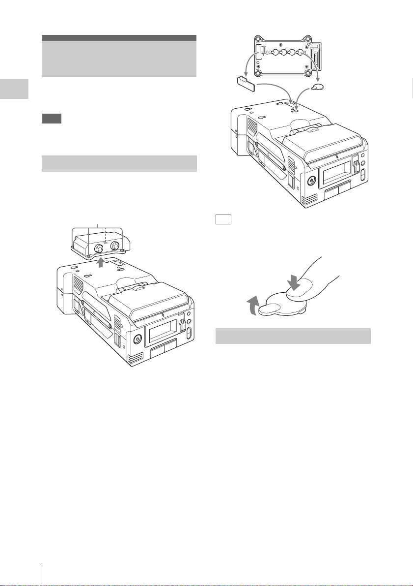
Removing the Audio Input Box
1 Loosen the four screws (M3) on the
audio input box, and lift the box
straight up.
Screws (M3)
Tip
Pressing the area in the illustration will make
removing the covers for the screw holes easier.
Attaching the Audio Input Box
2 Remove the covers stored on the bottom
of the audio input box, and attach them
to the holes on the recorder.
Removing and Attaching the Audio Input Box
16
1 Remove the covers attached to the
recorder, and attach them to the bottom
of the audio input box.
Be sure to store the removed covers on the
bottom of the audio input box to prevent
losing them.
2 Place the audio input box on the
recorder, and secure the four screws
(M3).
Align the two guides on the bottom of the
audio input box with the holes on the
recorder, and place it directly on the recorder.
There are also position alignment guide lines
on the front of the recorder and front of the
audio input box. Position the audio input box
so that the two guide lines align.
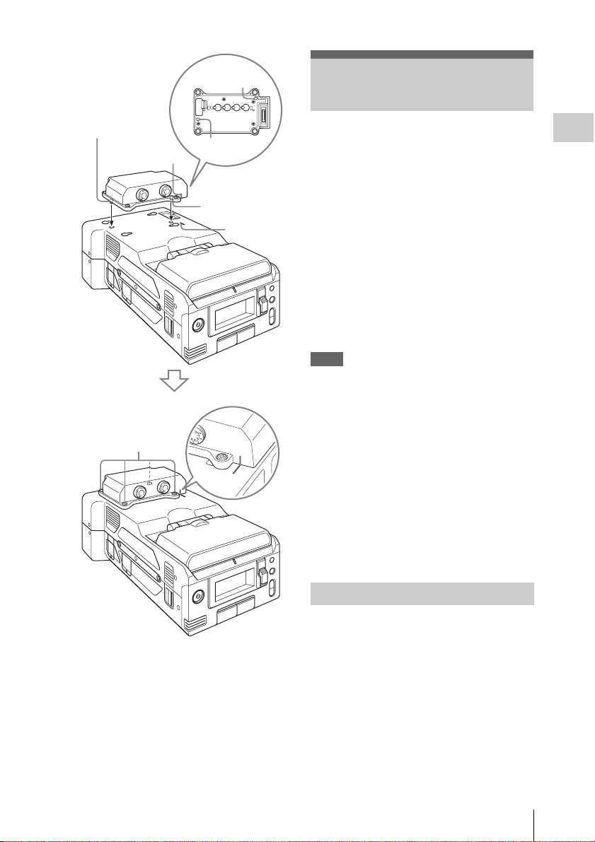
Guide
Using a Wi-Fi Connection
Guide
Guide line
Screws (M3)
Guide
Guide
Guide line
The recorder can connect to a computer,
smartphone, or tablet via Wi-Fi by attaching an
optional Wi-Fi adapter on the recorder. The
following Wi-Fi adapters are supported.
• CBK-WA100 Wireless Adapter
• IFU-WLM3 Wireless LAN USB Module
For details on the Wi-Fi connection method for the
CBK-WA100, refer to the operating instructions for
the CBK-WA100.
Making a Wi-Fi connection between a computer,
smartphone, or tablet and the recorder enables
you to do the following.
• Send planning metadata created on a computer to the
recorder, and set names of clips and shot marks.
• Display the Wi-Fi remote controller on a computer,
smartphone, or tablet to control the recorder remotely.
Notes
• Do not connect devices other than those specified to the
external device connector.
• Always turn off the power supply before attaching or
removing a CBK-WA100 or IFU-WLM3.
• When using the CBK-WA100, you cannot use the IFUWLM3.
• An i.LINK connection and USB wireless LAN module
cannot be used at the same time. When using a wireless
connection with an IFU-WLM3 inserted directly into the
external device connector, do not connect a device to the
i.LINK connector.
• The IFU-WLM3 USB Wireless LAN Module (sold
separately) may not be available in some countries/
regions.
• Using other wireless devices near the recorder may
result in improper operation of the recorder. Turn off
wireless devices near the recorder whenever possible.
Preparations
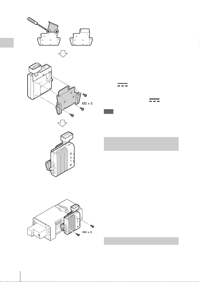
Attaching the CBK-WA100
1 Remove the top part of the bracket, and
secure the main part of the bracket to
the CBK-WA100 using the three screws
(M2×5) supplied with the CBK-WA100.
Using a Wi-Fi Connection
17
Preparations
recorder to the Mini USB connector on
the CBK-WA100.
4 Use the BNC cable supplied with the
CBK-WA100 to connect the SDI OUT
1/2 connector (page 6) on the recorder
to the SDI IN connector on the CBKWA100.
5 When supplying power to the CBK-
WA100 from the recorder, use the DC
power supply cable supplied with the
CBK-WA100 to connect the DC OUT
connector (page 6) on the recorder to
the (DC IN) connector on the
CBK-WA100.
When using a separately supplied AC
adapter, connect it to the (DC IN)
connector on the CBK-WA100.
Note
Power can only be supplied to an external device from
either the DC OUT connector or the external device
connector. They cannot both be used to supply power at
the same time.
Connecting to Wi-Fi with the CBKWA100
2 Secure the CBK -WA100 to the recorder
using the two screws (M4×6) supplied
with the CBK-WA100.
3 Use the USB cable supplied with the
CBK-WA100 to connect the external
device connector (page 6) on the
Using a Wi-Fi Connection
18
1 Turn on the recorder.
2 When supplying power to the CBK-
WA100 from the recorder, set
[OTHERS] >[Power Enable] in the
setup menu to [Sony Wireless Adapter].
The recorder will restart after you change the
setting.
3 Set the output signal from the SDI OUT
connector that is connected to the CBKWA100 to [SD] or [HD] in the [VIDEO
SET] >[SDI/HDMI/i.LINK I/O Select]
setup menu.
4 Turn on the CBK-WA100.
Using the Web Menu
You can operate the Web menu built in the
recorder from a computer when it is connected to
the recorder via a Wi-Fi connection.
Using the Web menu, you can check the recorder
information and operation settings, and upload
planning metadata files.
Note
The Web menu cannot be accessed during recording or
playback. (Files cannot be transferred over a Wi-Fi
connection.)
Example Web menu
[Product Information]
• Model name
• Serial No.
[Network]
• MAC Address
• IP Address
• Subnet Mask
[Wi-Fi Status]
• Wireless Mode
•SSID
• Type
• Channel
• Authentication (network authentication)
• Data Encryption (data encryption)
[Planning Metadata]
Clicking [Upload] allows you to upload a
planning metadata file (page 19).
Note
The configuration of items displayed in the Web menu
varies depending on the browser you are using.
4 Select the planning metadata file you
want to upload, and then click [Open].
5 Click [Execute].
The planning metadata file is loaded into the
recorder’s memory and stored in the media.
“OK” appears in the Status field when the
transfer is complete.
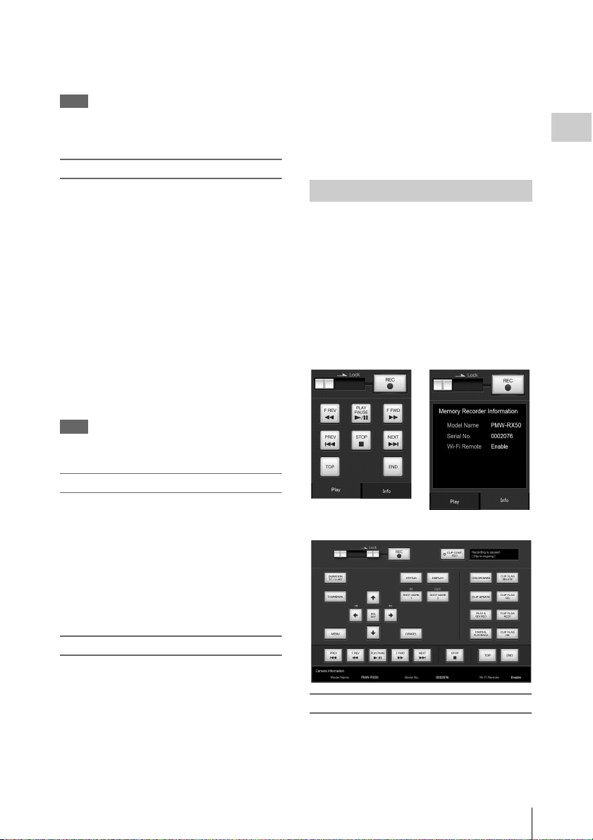
Using Wi-Fi Remote Control
When the recorder is connected via Wi-Fi, the
built-in Wi-Fi remote recorder can be accessed
from a smartphone, tablet, computer, or other
device.
The recorder can be controlled remotely using the
Wi-Fi remote controller. Playback and recording
can be controlled remotely, making operation
convenient, for example, when the recorder is in
a fixed remote location.
[Wi-Fi Remote] screen (smartphone)
Preparations
To display the Web menu
1 Launch a browser on the computer, and
navigate to “http://<recorder’s IP
address>/.”
2 Enter the user name and password, and
click [OK].
User name: admin
Password: pmw-rx50
To upload a planning metadata file
1 Insert a media such as an SxS memory
card.
2 Click [Upload] in the Web menu.
3 Click [Select] to show [Choose File]
dialog.
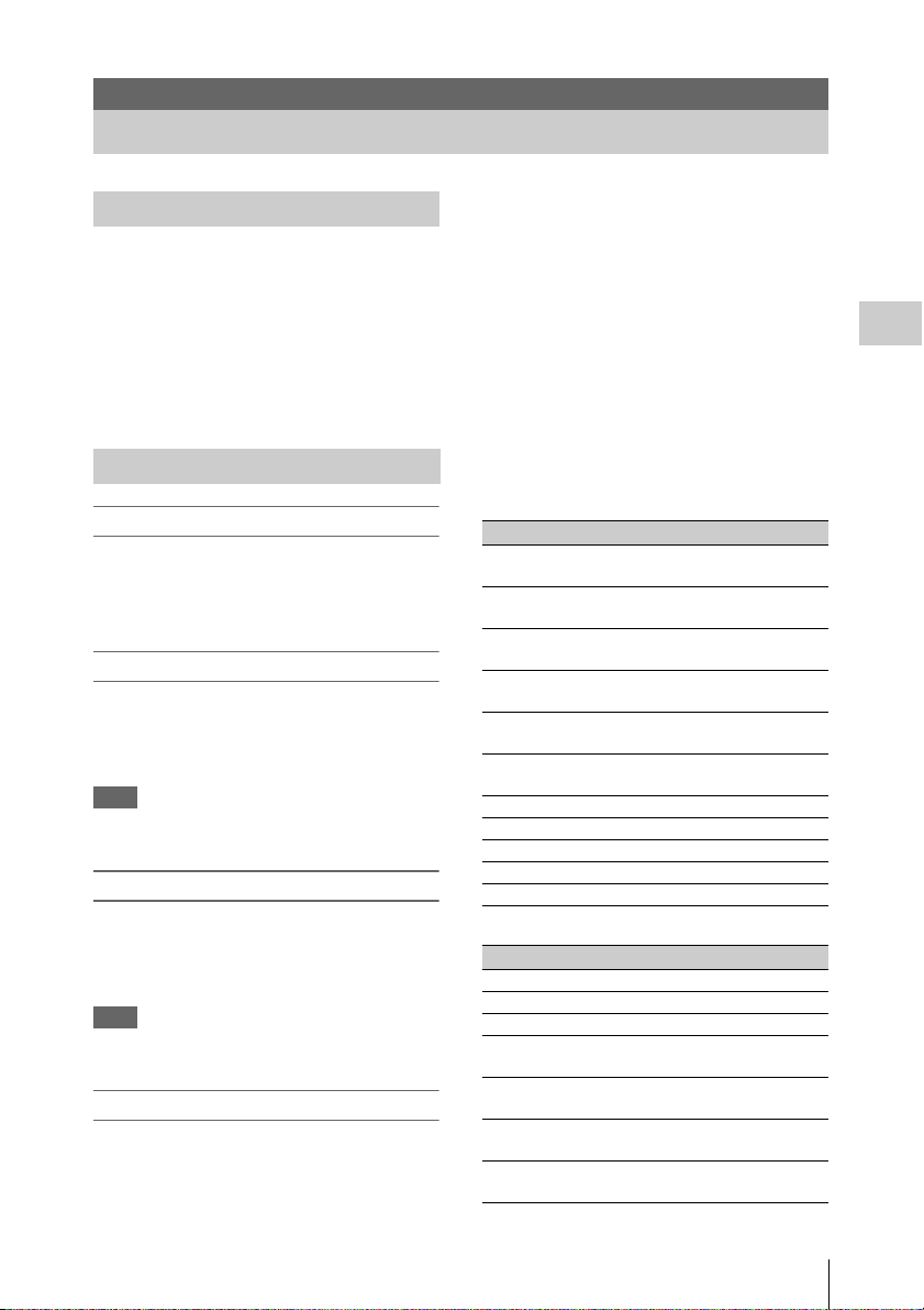
[Wi-Fi Remote] screen (tablet)
To display the Wi-Fi remote controls
The recorder and device must be configured to
display the Wi-Fi remote controls on the device
screen.
Using a Wi-Fi Connection
19

Configuring the recorder
1 Set [OTHERS] >[Wi-Fi] >[Wi-Fi] in the
setup menu to [Enable].
2 Set [OTHERS] >[Wi-Fi] >[Wi-Fi
Remote] in the setup menu to [On].
Preparations
Configuring the device
Configure the smartphone, tablet, computer, or
other device.
1 Connect the recorder and device via
Wi-Fi.
For details about connecting the
CBK-WA100 and IFU-WL M3 via Wi-Fi, refer to
the operating instructions for each device.
2 Launch a browser on the device and
access the “http://recorder IP address
([OTHERS] >[Network] >[IP
Address])/rm.html” URL.
Example; Enter “http://192.168.1.10/
rm.html” in the address bar if the IP
address is 192.168.1.10.
The [Wi-Fi Remote] screen appears on the
device when successfully connected.
Thereafter, operate the recorder using the
controls on the screen.
Sliding the Lock knob to the right allows you
to prohibit REC button operation.
Notes
• To display the page designed for smartphones, enter a
URL ending in “rms.html.” To display the page
designed for tablets, enter a URL ending in “rmt.html.”
Normally, entering a URL ending in “rm.html”
automatically displays each page. Note that the
controller may not operate correctly on some devices.
• The recorder status may not match the [Wi-Fi Remote]
screen under the following circumstances. If this
occurs, refresh the browser display.
—When the recorder is restarted during a connection
—When the recorder is operated during a connection
—When the device is reconnected
—When the Back/Next buttons in the browser are used
• Wi-Fi Remote may not function if the wireless status
(signal strength) deteriorates significantly.
• Some smartphones and tablet devices may not be
equipped with ad-hoc mode support. For details, refer to
the operating instructions for your smartphone or tablet.
Device OS Browser
PC Windows 7
SP1
Windows 8.1 Internet Explorer 11
Mac OS 10.7
OS 10.8
Smartphone Android 4.1, 4.2,
4.3
iOS 6, 7 Safari
Tablets Android 4.1, 4.2,
4.3
iOS 6, 7 Safari
Internet Explorer 11
Safari
Chrome
Chrome
Supported devices
The following devices, OS, and browsers (and later
versions) support Wi-Fi remote control operation.
Using a Wi-Fi Connection
20
Recording
Changing Basic Settings
Selecting an Input Signal
To record or output a signal, either SDI or i.LINK
must be selected as the input signal source. The
setting is made in [Input Source Select] in the
[VIDEO SET] menu.
If i.LINK is selected, output to i.LINK is not
possible.
In UDF/HD mode and exFAT mode, i.LINK
cannot be selected.
Video Formats
Switching between UDF/exFAT/FAT
Switch by setting [F.Sys.] under [System] (page
57) in the [OTHERS] menu.
After switching this setting, the recorder will
automatically restart.
Switching between HD Mode/SD Mode
For [HD/SD] switching, use [System] (page 57)
in the [OTHERS] menu.
When you change the menu setting, the recorder
automatically restarts, executing the switching.
Note
[UDF/exFAT/FAT] and [HD/SD] switching is disabled
during recording and playback.
Switching between XAVC/MPEG2
Switch by setting [XAVC/MPEG2] under
[System] (page 57) in the [OTHERS] menu.
This can be selected when [F.Sys.] is set to
[exFAT] and [HD/SD] is set to [HD].
Note
You cannot switch between XAVC/MPEG2 during
recording or playback.
Changing the format
The format of the input signal connected to the
SDI IN connector must match the video format
set in [Rec Format] (page 58) in the [OTHERS]
menu.
The format of the signals output from the SDI
OUT 1/2, VIDEO OUT, and HDMI OUT
connectors changes according to the video format
setting.
Selectable formats vary depending on the UDF/
exFAT/FAT, HD/SD, and usage region (NTSC/
PAL) settings (page 57).
The supported video format settings and
corresponding supported input formats are shown
below.
For details about the output signal format, see
“Formats and Limitations of Outputs” (page 76).
For NTSC
UDF/HD mode
[Rec Format] setting Input signal format
HD422 50/1080/59.94i 1080/59.94i, 1080/
29.97PsF
HQ 1920×1080/59.94i 1080/59.94i, 1080/
29.97PsF
HQ 1440×1080/59.94i 1080/59.94i, 1080/
29.97PsF
HD422 50/1080/29.97P 1080/59.94i, 1080/
29.97PsF
HQ 1920×1080/29.97P 1080/59.94i, 1080/
29.97PsF
HQ 1440×1080/29.97P 1080/59.94i, 1080/
29.97PsF
HD422 50/1080/23.98P 1080/23.98PsF
HQ 1920×1080/23.98P 1080/23.98PsF
HQ 1440×1080/23.98P 1080/23.98PsF
HD422 50/720/59.94P 720/59.94P
HQ 1280×720/59.94P 720/59.94P
exFAT/HD mode
[Rec Format] setting Input signal format
XAVC-I 1080/59.94P 1080/59.94P
XAVC-L50 1080/59.94P 1080/59.94P
XAVC-L35 1080/59.94P 1080/59.94P
XAVC-I 1080/59.94i 1080/59.94i, 1080/
29.97PsF
XAVC-L50 1080/59.94i 1080/59.94i, 1080/
29.97PsF
XAVC-L35 1080/59.94i 1080/59.94i, 1080/
29.97PsF
XAVC-L25 1080/59.94i 1080/59.94i, 1080/
29.97PsF
Recording
Changing Basic Settings
21

[Rec Format] setting Input signal format
XAVC-I 1080/29.97P 1080/59.94i, 1080/
XAVC-L50 1080/29.97P 1080/59.94i, 1080/
XAVC-L35 1080/29.97P 1080/59.94i, 1080/
XAVC-I 1080/23.98P 1080/23.98PsF
XAVC-L50 1080/23.98P 1080/23.98PsF
XAVC-L35 1080/23.98P 1080/23.98PsF
XAVC-I 720/59.94P 720/59.94P
XVAC-L50 720/59.94P 720/59.94P
HD422 50/1080/59.94i 1080/59.94i, 1080/
Recording
HQ 1920×1080/59.94i 1080/59.94i, 1080/
HQ 1440×1080/59.94i 1080/59.94i, 1080/
HD422 50/1080/29.97P 1080/59.94i, 1080/
HQ 1920×1080/29.97P 1080/59.94i, 1080/
HQ 1440×1080/29.97P 1080/59.94i, 1080/
HD422 50/1080/23.98P 1080/23.98PsF
HQ 1920×1080/23.98P 1080/23.98PsF
HQ 1440×1080/23.98P 1080/23.98PsF
HD422 50/720/59.94P 720/59.94P
HQ 1280×720/59.94P 720/59.94P
29.97PsF
29.97PsF
29.97PsF
29.97PsF
29.97PsF
29.97PsF
29.97PsF
29.97PsF
29.97PsF
FAT/HD mode
[Rec Format] setting Input signal format
HQ 1920×1080/59.94i 1080/59.94i, 1080/
HQ 1440×1080/59.94i 1080/59.94i, 1080/
SP 1440×1080/59.94i 1080/59.94i, 1080/
HQ 1920×1080/29.97P 1080/59.94i, 1080/
HQ 1440×1080/29.97P 1080/59.94i, 1080/
HQ 1920×1080/23.98P 1080/23.98PsF
HQ 1440×1080/23.98P 1080/23.98PsF
HQ 1280×720/59.94P 720/59.94P
29.97PsF
29.97PsF
29.97PsF
29.97PsF
29.97PsF
UDF/SD mode
[Rec Format] setting Input signal format
DVCAM 59.94i 480/59.94i
IMX50 59.94i 486/59.94i
exFAT/SD mode
[Rec Format] setting Input signal format
DVCAM 59.94i 480/59.94i
IMX50 59.94i 486/59.94i
FAT/SD mode
[Rec Format] setting Input signal format
DVCAM 59.94i 480/59.94i
For PAL
UDF/HD mode
[Rec Format] setting Input signal format
HD422 50/1080/50i 1080/50i, 1080/25PsF
HQ 1920×1080/50i 1080/50i, 1080/25PsF
HQ 1440×1080/50i 1080/50i, 1080/25PsF
HD422 50/1080/25P 1080/50i, 1080/25PsF
HQ 1920×1080/25P 1080/50i, 1080/25PsF
HQ 1440×1080/25P 1080/50i, 1080/25PsF
HD422 50/720/50P 720/50P
HQ 1280×720/50P 720/50P
exFAT/HD mode
[Rec Format] setting Input signal format
XAVC-I 1080/50P 1080/50P
XAVC-L50 1080/50P 1080/50P
XAVC-L35 1080/50P 1080/50P
XAVC-I 1080/50i 1080/50i, 1080/25PsF
XAVC-L50 1080/50i 1080/50i, 1080/25PsF
XAVC-L35 1080/50i 1080/50i, 1080/25PsF
XAVC-L25 1080/50i 1080/50i, 1080/25PsF
XAVC-I 1080/25P 1080/50i, 1080/25PsF
XAVC-L50 1080/25P 1080/50i, 1080/25PsF
XAVC-L35 1080/25P 1080/50i, 1080/25PsF
XAVC-I 720/50P 720/50P
XAVC-L50 720/50P 720/50P
HD422 50/1080/50i 1080/50i, 1080/25PsF
HQ 1920×1080/50i 1080/50i, 1080/25PsF
HQ 1440×1080/50i 1080/50i, 1080/25PsF
HD422 50/1080/25P 1080/50i, 1080/25PsF
HQ 1920×1080/25P 1080/50i, 1080/25PsF
HQ 1440×1080/25P 1080/50i, 1080/25PsF
HD422 50/720/50P 720/50P
HQ 1280×720/50P 720/50P
FAT/HD mode
[Rec Format] setting Input signal format
HQ 1920×1080/50i 1080/50i, 1080/25PsF
HQ 1440×1080/50i 1080/50i, 1080/25PsF
SP 1440×1080/50i 1080/50i, 1080/25PsF
HQ 1920×1080/25P 1080/50i, 1080/25PsF
HQ 1440×1080/25P 1080/50i, 1080/25PsF
HQ 1280×720/50P 720/50P
Changing Basic Settings
22

UDF/SD mode
[Rec Format] setting Input signal format
DVCAM 50i 576/50i
IMX50 50i 576/50i
exFAT/SD mode
[Rec Format] setting Input signal format
DVCAM 50i 576/50i
IMX50 50i 576/50i
FAT/SD mode
[Rec Format] setting Input signal format
DVCAM 50i 576/50i
Time Data
Setting the Timecode
Specify the timecode to be recorded with
[Timecode] and [TC For mat] in the [TC/UB SET]
menu (page 53). The following methods are
available for recording the timecode.
Preset mode (Preset)
Records an internally generated timecode with a
preset initial value. You can select one of the
following run modes.
• Free Run: Timecode is always running.
• Rec Run: Timecode runs only when recording.
Regeneration mode (Regen)
Records an internally generated timecode that
continues from the timecode of the last recorded
clip.
External regeneration mode (ExtRegen)
Records an internally generated timecode that is
synchronized to th e timecode superimposed on an
external input signal. If a timecode is not
superimposed on an input SDI signal, the value of
the internal timecode generator is used as the
initial value.
Displaying the Time Data
Pressing the DISPLAY button displays the time
data on the screen (page 9). The indication is
switched among the timecode, user bits, and
recording duration by pressing the DURATION/
TC/U-BIT button (page 6).
Display Contents
TCG **:**:**:** Timecode
TCR **:**:**:** Timecode superimposed on the
input signal
CLK **:**:**:** Timecode (Clock mode)
UBG ** ** ** ** User bits
UGR ** ** ** ** User bits superimposed on the
input signal
DUR **:**:** Duration from the beginning of
recording
Setting the Output Mode
The output mode of the video signal output on the
SDI OUT 1 connector can be selected when
editing while simultaneously outputting video.
The setting is made in [SDI OUT1 Mode Select]
of the [VIDEO SET] menu. The image on the
LCD monitor is output from the SDI OUT 2,
HDMI, VIDEO OUT, and i.LINK connectors.
[Normal] mode: The same video as that
displayed on the LCD monitor is output.
[Through] mode: The SDI IN input signal is
always output, regardless of the operating state.
[Auto] mode: The playback video is output
during playback operations on the recorder
(PLAY/PAUSE, F FWD, F REV). In all other
cases, the SDI IN input signal is output.
In Auto mode, [SDI/HDMI/Video Out Super]
(page 51) in the [VIDEO SET] menu is set to
[Off], and no character information is output.
Recording
Setting the Users Bit
You can add a hexadecimal number of 8 digits for
pictures as the user bits.
The user bits can also be set to the current date.
Use [Users Bit] (page 53) in the [TC/UB SET]
menu.
Changing Basic Settings
23

Recording
Note
Using mobile phones and wireless devices near the
recorder may result in recording and playback stops due
to frequency and power outputs. Use such devices at a
distance that does not affect the recorder.
1 Select the input signal to record in
[Input Source Select] in the [VIDEO
Recording
SET] menu.
2 Press and hold the REC button, then
press the PLAY/PAUSE.
The “zREC” indication flashes if normal
recording does not occur, for example, if the
specified video format is different to the
input signal format or if there is no input
signal.
To stop recording
Press the STOP/EE button.
Recording stops, and the recorder switches to EE mode.
To delete clips
You can delete the last recorded clip by using the
[Last Clip DEL] function (page 27). Use the [All
Clips DEL] function (page 27) to delete all
recorded clips from an SxS memory card. To
specify a clip to be deleted, operate the recorder
from the thumbnail screen (page 32).
Clip (recording data)
When you stop recording, video, audio and
subsidiary data from the start to end of the
recording are recorded as a single clip on an SxS
memory card.
Clip name
For each clip recorded with this recorder, a clip
name is automatically generated according to the
method selected with [Auto Naming] in [Clip]
(page 59) in the [OTHERS] menu.
The default setting of [Auto Naming] is [Plan].
With this setting, a clip name defined in planning
metadata is applied if a planning metadata file is
loaded into the recorder.
Change the [Auto Naming] setting to [Title] to
apply a clip name composed of 4 to 46
alphanumerics and 4 numerics.
Example: ABCD0001
The block of 4 to 46 alphanumerics can be
specified as desired using [Clip] in the [OTHERS]
menu before you start recording. (It cannot be
changed after recording.)
The value of the 4 numerics is automatically
counted up in sequence.
Notes on Clips
The maximum file size for a clip is 43 GB for UDF
and exFAT modes, 4 GB for FAT/HD mode, and 2
GB for FAT/SD mode.
If you record continuously for an extended period,
the recorded material may be split into multiple
files due to file size restrictions (up to 99 separate
files).
In FAT mode, material that was split into multiple
files will still be treated as a single clip by the
recorder.
A long clip can be recorded crossing over two
memory cards in slot A and B.
When you copy recorded clips to a hard disk drive,
etc. using a computer, it is recommended to
download and use the dedicated application
software (page 10).
Note
If copying is done using “Explorer” (Windows) or
“Finder” (MAC), the continuity and relationships of
recorded materials may not be maintained.
Maximum duration of a clip
The maximum clip length is 24 hours for FAT
(MP4 or AVI) and 6 hours for UDF (MXF) and
exFAT (MXF).
If you exceed the maximum clip length, a new clip
will be automatically created. You can check the
new clip on the thumbnail screen.
24
Recording

Useful Functions
Note
Shot marks cannot be recorded onto write-protected SxS
memory cards. Also, shot marks cannot be inserted at the
start or end of a clip.
Color Bars/Reference Tone
By setting [Color Bars On/Off] (page 49) in the
[VIDEO SET] menu to [On], you can output a
color-bar signal in place of the camera picture.
When this item is set to [Off], the output returns
to the camera picture.
A 1 kHz reference tone is output with the color
bar signal if [1KHz Tone] in [Audio Output]
(page 49) in the [AUDIO SET] menu is set to
[On].
The color-bar signal and reference-tone signal are
also fed out from the SDI OUT 1/2, HDMI OUT,
i.LINK, VIDEO OUT (color bars only), and
AUDIO OUT connectors (reference audio signal
only).
You can select the type of color bars with [Color
Bars Type] in the [VIDEO SET] menu.
Shot Marks
Shot marks can be recorded at important audio/
video scenes for clips recorded in UDF, exFAT or
FAT/HD mode. Using shot marks enables the
target scenes to be quickly and easily cued up on
the Shot Mark screen (page 41).
The recorder permits you to record two types of
shot marks: shot mark 1 and shot mark 2.
Shot marks can be inserted as needed during
recording or can be added after recording while
checking the playback pictures on the thumbnail
screen.
The recorder can use shot mark 1 and shot mark 2
as the in-point and out-point, respectively, for inpoint to out-point partial playback (page 34).
Inserting a shot mark during recording
Assign [Shot Mark1] and [Shot Mark2] to the
assignable buttons (page 26), and press the
buttons at the scenes you want the shot marks
inserted during recording.
Inserting a shot mark during playback
Press the assignable buttons to which [Shot
Mark1] and [Shot Mark2] are assigned at the
scenes you want the shot marks inserted during
clip playback.
exFAT FAT/HD
UDF
Shot marks can also be added and deleted using
the Shot Mark screen (page 41).
For operation to apply a name to a shot mark, see
“Defining Shot Mark names in Planning Metadata”
on page 30.
OK/NG/KP Flags
You can add OK/NG/KP flags to clips recorded
with UDF or exFAT. By adding flags, you can set
the recorder to display only clips with certain flag
settings on the thumbnail screen (OK/NG/KP/
None-Clip thumbnail screen) (page 33).
Note
Use the [Lock Clip] setting (page 37) to protect clips.
Adding a flag
During recording or playback, press the
assignable button to which you assigned the [Clip
Flag OK/Clip Flag NG/Clip Flag Keep] function.
Deleting a flag
Press the assignable button, twice in succession,
to which you assigned the [Clip Flag OK/Clip
Flag NG/Clip Flag Keep] function.
OK/NG/KP flags can also be added and deleted from
the thumbnail screen. For details, see “OK/NG/KP
Flag” (page 38).
OK Mark
By adding the OK mark to a clip recorded in FAT
HD Mode, you can prevent the clip from being
deleted or divided inadvertently. You can also set
the recorder to display only clips with the OK
mark on the thumbnail screen (OK-Clip
thumbnail screen) (page 33).
Adding the OK mark
When recording of a clip ends, press the
assignable button to which you assigned the [OK
Mark] function.
While standing by to record, you can also add an
OK mark to the last-recorded clip ([Last Clip]) on
the selected memory card.
FAT/HD
UDF
exFAT
Recording
Useful Functions
25

Deleting the OK mark
Press the assignable button to which you assigned
the [OK Mark] function, and select [Execute].
While standing by to record, you can also delete
the OK mark from the clip with the last-added OK
mark.
Adding or deleting the OK mark to or from clips
before the last one
Make changes via the thumbnail screen (page
39).
Assignable Buttons
Recording
The recorder has five assignable buttons (page 7)
to which you can assign various functions for
convenience.
To change functions
Use [Assign Button] (page 56) in the [OTHERS]
menu.
The assigned functions can be viewed on the
Button/Remote status screen (page 44).
Clip Continuous Recording
UDF
exFAT
Clips are normally created individually for each
time you start and sto p recording, but you can also
continue recording to a single clip regardless of
the number of times you start and stop recording
by using the Clip Continuous Recording function,
which will add recordings to the same clip until
the function is disabled or turned off.
This is convenient for when you do not want to
create a large number of short clips, or when you
do not want to be restricted by a maximum
number of clips.
A recording start mark is added to each point at
which you resume recording, making it easy to
search for each point.
Preparatory settings
Set [Clip Cont. Rec Setting] (page 51) in the
[VIDEO SET] menu to [On].
When you set [Setting] to [On] the [Clip
Continuous Recording] function is enabled, and
“CONT” appears on the screen (page 9).
You can also assign [Clip Continuous Rec] to an
assignable button (page 26), and set to [On]/[Off]
by pressing the button.
Notes
• Clip Continuous Recording cannot be used while
recording.
• This function cannot be used with FAT.
Performing clip continuous recording
Press and hold the REC button, then press
the PLAY/PAUSE.
When recording starts, the “CONT” ind ication on
the screen changes to “zREC” (with z in red).
To pause recording, press the PLAY/PAUSE
button. To resume, press and hold the REC
button, then press the PLAY/PAUSE button.
Pressing the STOP/EE button closes the clip. In
clip continuous mode, the “CONT” indicator
flashes if there is no continuous clip.
When operating the IR Remote Commander,
press the START/STOP button to start recording,
and press the START/STOP button or PAUSE
button to stop recording. To resume, press the
START/STOP button again. Pressing the STOP
button will close the clip.
Notes
• If you remove the SxS memory card or the battery
while recording or standing by to record (the “CONT”
indication appears), the SxS memory card must be
restored. Only remove the SxS memory card after Clip
Continuous Recording is complete. If “CONT” is
flashing (1 time per second), you can remove the SxS
memory card.
• Record for at least 2 seconds before you stop
recording.
• If [Input Source Select] is set to [i.LINK], the [Clip
Continuous Recording] function is disabled.
To disable Clip Continuous Recording mode
While standing by to record, set [Clip Cont. Rec
Setting] (page 51) in the [VIDEO SET] menu to
[Off].
Restricted operations
If you perform any of the following operations
while recording or standing by to record, 1
continuous clip will not be created. The next time
you start recording, a new clip will be created.
• Performing clip operations (locking, deleting,
or changing the names of clips).
• Switching the memory card slot.
• Changing the recording format.
• Setting the power button to OFF.
• Displaying the thumbnail screen.
• Playing clips.
Useful Functions
26

Loop Recording
UDF
exFAT
You can continue recording video for a fixed
interval by alternately recording and deleting
video using two SxS memory cards.
Preparatory settings
Set [Segment Loop Rec] (page 51) in the
[VIDEO SET] menu to [On]. Loop recording is
enabled, and “SL-REC” appears on the screen
(page 9).
Set the recording retention time in [Segment
Duration].
In loop recording, the recording time that is
retained of a clip varies depending on the
recording status of the memory card when
recording was stopped. When [15~35min] is
selected in [Segment Duration], a minimum of
15 minutes and a maximum of 35 minutes is
retained. When [15~35min] is selected, a
minimum of 25 minutes free capacity is required
on each SxS memory card. When [30~65min] is
selected, a minimum of 40 minutes free capacity
is required.
Notes
• Use SxS memory cards for loop recording. Recording
to other memory cards using a media adapter is not
supported.
• Loop recording is not supported in FAT mode.
Starting loop recording
Press and hold the REC button, and press the
PLAY/PAUSE button.
Recording starts and “zREC” appears on the
screen.
Pressing the STOP/EE button stops recording and
closes the clip. Simultaneously, the [Segment
Loop Rec] setting is set to [Off].
If the REC button and PLAY/PAUSE button are
pressed simultaneously during loop recording,
the recorder switches to normal recording and
continues recording the clip seamlessly. After
switching, the “SL-REC” indication on the screen
disappears.
Notes
• In loop recording, video on the SxS memory cards is
repeatedly recorded and deleted, shortening t he rewrite
life of the cards. Accordingly, check the remaining life
of the memory cards periodically.
• If using loop recording continuously for longer than
one week, restart the recorder once per week. Also, if
the loop stops operating or other abnormality appears
during operation, restart the recorder.
Restricted operations
If you perform any of the following operations
while loop recording, the recorder will switch to
normal recording and the [Segment Loop Rec]
setting will be set to [Off] automatically.
• Switching the memory card slot
• Ejecting media that is not recording
Deleting Clips
While standing by to record, the [Last Clip DEL]
function for deleting the last recorded clip and the
[All Clips DEL] function for deleting all clips
from an SxS memory card are available.
For clip deletion on the thumbnail screen, see
“Deleting Clips” on page 39.
To delete using the assignable button
Assign the [Last Clip DEL] function to one of the
assignable buttons (page 26) in advance.
Press the assignable button to which you have
assigned [Last Clip DEL], and select [Execute] to
delete the last recorded clip from the SxS memory
card.
To delete using the Setup menu
Select [Last Clip DEL] in [Clip] (page 59) in the
[OTHERS] menu, select [Execute], then select
[Execute] again to delete the last recorded clip
from the SxS memory card.
Note
When Clip Continuous Recording is set to [On], [Last
Clip DEL] cannot be sel ected.
Deleting clips collectively
Select [All Clips DEL] in [Clip] (page 59) in the
[OTHERS] menu, select [Execute], then select
[Execute] again to delete all the clips from the
SxS memory card.
Notes
• If the SxS memory card contains clips of both of HD
Mode and SD Mode, only the clips of the currently
selected mode are deleted.
• Clips with the OK m ark (page 25) cannot be deleted in
FAT mode. In UDF or exFAT mode, clips set to [Lock
Clip] (page 37) cannot be deleted.
Recording
Useful Functions
27

Storing/Retrieving the Setting Data
You can store all the menu settings as a setup file
on an SxS memory card or a USB flash drive.
By retrieving the stored setup file, the proper
setup condition can be immediately obtained.
Note
Values for [Clock Set] and [Hours Meter] in the
[OTHERS] menu are not stored.
Recording
Storing the Setup file
To use an SxS memory card
Only one setup file—designated with the file
name “SETUP.SUF”—can be stored on one SxS
memory card.
1 Insert a memory card on which you
wish to store the setup file to a card slot.
Check that the inserted card is selected.
2 Select [Store(SxS)] in [Setup Data]
(page 55) in the [OTHERS] menu, then
select [Execute].
Note
If a setup file already exists on the memory card you
specified in Step 1, a message to confirm whether to
overwrite the file is displayed.
To use a USB flash drive
Connect the formatted USB flash drive to the
external device connector.
Select [Store(USB)] >[Execute] in step 2.
UDF exFAT
Retrieving the Setup file
To use an SxS memory card
When you retrieve the stored setup file, the
recorder settings are changed according to the
file.
1 Insert the memory card on which you
stored the setup file into a card slot.
Check that the inserted card is selected.
2 Select [Recall(SxS)] in [Setup Data]
(page 55) in the [OTHERS] menu, then
select [Execute].
To use a USB flash drive
Connect the formatted USB flash drive to the
external device connector.
Select [Recall(USB)] >[Execute] in step 2.
UDF exFAT
Resetting to the standard values
The current recorder settings you made through
various menu and button operations can be
collectively returned to the standard statuses
(factory settings) by executing [All Reset] in the
[OTHERS] menu.
Planning Metadata
Planning metadata is information about shooting
and recording plans, recorded in an XML file.
You can shoot using clip names and shot mark
names defined in advance in a planning metadata
file.
This recorder can display clip names and shot
mark names defined in the following languages:
English/Chinese/German/French/Italian/
Spanish/Dutch/Portuguese/Swedish/
Norwegian/Danish/Finnish
Notes
• If you define clip and shot mark names in languages
other than those listed above, they may not be
displayed on the LCD monitor.
• If you define clip and shot mark names in French,
Dutch, or Finnish, some characters are displayed in a
different but similar font.
Loading a Planning Metadata file
To record planning metadata together with clips,
it is necessary to load a planning metadata file
into the recorder’s memory in advance.
To use an SxS memory card
Insert the SxS memory card with the planning
metadata file (.xml) saved to the directory below
into the recorder’s card slot, then select and load
the file via [Load / Slot(A)] or [Load / Slot(B)] in
[Plan.Metadata] (page 60) in the [OTHERS]
menu.
UDF: General/Sony/Planning
exFAT: XDROOT/General/Sony/Planning
FAT: BPAV/General/Sony/Planning
To use a USB flash drive
Be sure to select [USB A] for [Power Enable]
(page 61) in the [OTHERS] menu beforehand.
UDF exFAT
Useful Functions
28

Notes
n
Proper operation may not be possible if the USB
flash drive is connected without selecting [USB
A].
1 Connect a USB flash drive formatted in
the FAT32 file system to the external
device connector.
A file list appears.
Note
The file list displays up to 64 files.
Even if the total number of planning metadata files
is 64 or less, all of the planning metadata files may
not appear if the directory where they are located on
the USB flash drive (General/Sony/Planning)
contains 512 or more files.
2 Select the file which you want to load in
the file list, then press the SEL/SET
button.
Confirming the detailed information in planning
metadata
After loading a planning metadata file into
memory of the recorder, you can check the details
of the file, such as the filename, time and date of
file creation, and the titles specified in the file.
Select [Properties] in [Plan.Metadata] (page 60)
in the [OTHERS] menu, then select [Execute].
Using the Wi-Fi connection
When connecting the unit with a computer via
Wi-Fi, the file transmission can be done accessing
the unit’s Web menu from a computer.
1 Launch the browser and input http://
<recorder’s IP address> (page 61) in the
address bar.
2 Input the user name and password, then
click [OK].
User name: admin
Password: pmw-rx50
Clearing the loaded planning metadata
To clear the planning data loaded in the recorder’s
memory, proceed as follows:
Select [Clear] > [Execute] in [Plan.Metadata]
(page 60) in the [OTHERS] menu.
Defining a clip name in Planning
Metadata
The following two types of clip name strings can
be written in a planning metadata file.
• ASCII-format name, which is displayed on the
LCD monitor
• UTF-8-format name, which is actually
registered as the clip name
You can select the type for displaying the clip
name with [Clip Name Disp] in [Plan.Metadata]
(page 60) in the [OTHERS] menu.
When you specify a clip name in planning
metadata, the name is displayed under the
operation status indication on the LCD monitor.
Example of clip name strings
Use a text editor to modify the description for the
<Title> tag.
The shaded fields in the example are clip name
strings. “Typhoon” is described in ASCII format
(up to 44 characters).
“Typhoon_Strikes_Tokyo” is described in UTF-8
format (up to 44 bytes).
Here, “sp” indicates a space, and 3 indicates a
carriage return.
version="1.0"spencoding="
<?xml
sp
UTF-8"?>3
<PlanningMetadata
xmlns.sony.net/pro/metadata/
planningmetadata"
P0001"
creationDate="
sp
2011-08-20T17:00:00+09:00"
lastUpdate="
2011-09-28T10:30:00+09:00"
version="1.00">3
<Properties
assignment"
2011-09-28T10:30:00+09:00"
modifiedBy="Chris">3
<Title
xml:lang="en">
</Title>3
</Properties>3
</PlanningMetadata>3
Notes
• When you create a file, enter each statement as a single
line by breaking a line with a CRLF only after the last
character of the line, and do not enter spaces except
where specified with “sp.”
xmlns="http://
sp
assignId="
sp
propertyId="
sp
update="
sp
usAscii=" "
sp
Typhoo
Typhoon_Strikes_Tokyo
sp
sp
sp
sp
Recording
Useful Functions
29
 Loading...