

Page 1

4-459-611-18(1)
Solid-State Memory
Camcorder
PMW-F55
PMW-F5
Operating Instructions
Before operating the unit, please read this manual thoroughly
and retain it for future reference.
© 2013 Sony Corporation
Page 2

Table of Contents
Overview
Preparations
Features ...................................................................................... 6
System Configuration ............................................................... 9
Location and Function of Parts ............................................. 11
On-Screen Indications ............................................................ 17
Sub Display Screen ...................................................... 17
Viewfinder Screen ........................................................ 20
Power Supply ........................................................................... 23
Using a Battery Pack .................................................... 23
Using AC Power (DC IN Power) ................................. 24
Setting the Clock ..................................................................... 24
Attaching Optional Devices .................................................... 25
Attaching a Lens .......................................................... 25
Attaching a Viewfinder ................................................ 26
Setting the Basic Action .......................................................... 27
System Frequency ........................................................ 27
Shooting Mode ............................................................. 27
Main Recorded Signal .................................................. 27
Color Space .................................................................. 28
Imager Scan Mode ....................................................... 28
Recording Format ......................................................... 28
Using SxS Memory Cards ...................................................... 29
About SxS Memory Cards ........................................... 29
Inserting an SxS Memory Card .................................... 30
Removing an SxS memory card ................................... 30
Switching Between SxS Memory Cards ...................... 30
Formatting an SxS Memory Card ................................ 30
Checking the Remaining Time Available for
Recording ............................................................... 31
Restoring an SxS Memory Card .................................. 31
Using an SD Card ................................................................... 32
Usable SD Cards .......................................................... 32
Inserting an SD Card .................................................... 32
Removing an SD memory card .................................... 32
Formatting an SD Memory Card .................................. 32
Table of Contents
2
Page 3

Recording
Checking the Remaining Time ..................................... 32
Using an AXS-R5 .................................................................... 33
Attaching the AXS-R5 ................................................. 33
Removing the AXS-R5 ................................................ 33
Inserting an AXS Memory Card .................................. 33
Removing an AXS Memory Card ................................ 34
Recording to an AXS Memory Card ............................ 34
Formatting an AXS Memory Card ............................... 34
Checking the Remaining Time Available for
Recording ............................................................... 34
Restoring the AXS Memory Card ................................ 34
Using a USB Wireless LAN Module ...................................... 35
Attaching the IFU-WLM3 ............................................ 35
Making a Wi-Fi Connection ......................................... 36
Using the Wi-Fi Remote Commander .......................... 36
Basic Operation Procedure .................................................... 40
Changing Basic Settings ......................................................... 42
Electronic Shutter ......................................................... 42
Sensitivity/Gain/Color Temperature/
White Balance ........................................................ 42
Audio ............................................................................ 43
Time Data ..................................................................... 43
Useful Functions ...................................................................... 43
Assignable Buttons ....................................................... 43
Slow & Quick Motion .................................................. 44
Recording Time-lapse Video
(Interval Rec Function) .......................................... 44
Starting to Record from Pre-stored Video
(Picture Cache Function) ....................................... 45
Simultaneously Recording ........................................... 45
Rec Review .................................................................. 46
Focus Magnifier ........................................................... 46
False Color Display ...................................................... 46
Viewfinder Double Speed Drive Function ................... 46
Table of Contents
3
Page 4

Thumbnail Screens
Settings
Thumbnail Screens ................................................................. 47
Configuration of the Screen ......................................... 47
Playing Clips ............................................................................ 48
Playing the Selected and Subsequent Clips in
Sequence ................................................................ 48
Clip Operations ....................................................................... 48
Operations of the Thumbnail Menu ............................. 48
Displaying the Detailed Information of a Clip ............. 49
Copying MPEG2 Proxy Data (PMW-F55 only) .......... 49
Deleting Clips ............................................................... 50
Changing Information on the Thumbnail Screen ......... 50
Sub Display Operation ........................................................... 51
Sub Display Setting Items ...................................................... 52
CAMERA Screen ......................................................... 52
FILE Screen ................................................................. 53
AU/TC (audio/timecode) Screen .................................. 54
Setup Menu Operations .......................................................... 56
User Menu .................................................................... 57
Setup Menu List ...................................................................... 59
Camera Menu ............................................................... 59
Paint Menu ................................................................... 68
Audio Menu ................................................................. 73
Video Menu .................................................................. 77
VF Menu ...................................................................... 80
TC/UB Menu ................................................................ 83
Recording Menu ........................................................... 84
Media Menu ................................................................. 85
File Menu ..................................................................... 86
Maintenance Menu ....................................................... 89
System Menu ................................................................ 90
External Devices Connection
Table of Contents
4
Connecting External Monitors and Recording Devices ...... 96
Operating Clips With a Computer ........................................ 97
External Synchronization ....................................................... 98
Page 5

Appendices
Important Notes on Operation .............................................. 99
Formats and Limitations of Outputs .................................. 101
Video Formats and Output Signals ............................ 101
Error/Warning Indications .................................................. 109
Error Indications .........................................................109
Warning Indications ................................................... 109
Caution and Operation Confirmation Indications ...... 110
Items Saved in the File .......................................................... 112
Licenses .................................................................................. 120
MPEG-2 Video Patent Portfolio License ................... 120
MPEG-4 Visual Patent Portfolio License .................. 120
MPEG-4 AVC Patent Portfolio License .................... 120
On accessing software to which the GPL/LGPL
applies .................................................................. 121
Open software licenses ............................................... 121
Specifications ......................................................................... 121
General ....................................................................... 121
Camera Section .......................................................... 123
Input/Output ............................................................... 124
Media .......................................................................... 124
Package Configuration ............................................... 124
Optional Accessories .................................................. 125
Index ....................................................................................... 128
Table of Contents
5
Page 6

Overview
Overview
Features
The PMW-F55/F5 is a highly compact,
lightweight and high-performance CineAlta 4K
camera with a 4K Super 35mm equivalent Singlechip CMOS image sensor.
The PMW-F55’s CMOS image sensor w ith frame
image scan function allows you to shoot clear 4K
images without rolling shutter distortion or flash
band phenomenon, for perfect HD recording
performance.
The PMW-F5’s 4K image sensor allows you to
record high quality HD pictures.
You can record in SR SStP/MPEG2 HD video
format, in addition to the new 4K-compatible
format, XAVC, by using an SxS memory card.
4K RAW data can be recorded by using the
portable memory recorder, AXS-R5, which
adopts the newly developed access memory card
(AXSM).
The camcorder adopts the same native FZ mount
used by the PMW-F3. You can use a variety of
cine lenses (PL mount) so that the PL/FZ
conversion adaptor comes standard.
By using the optional LA-FZB1/LA-FZB2 mount
adapter, the B4 lens that is widely used for
broadcasting can be attached. You can use your
lens libraries with this camcorder.
Compatible with multi format
The camcorder is compatible with the new
format, XAVC (official name: MPEG4 AVC/
H.264 Hi422 Profiles/Level 5.2), and can record
4K: 4096 × 2160, QFHD: 3840 × 2160, 2K: 2048
× 1080, HD: 1920 × 1080.
The camcorder is also compatible with frame
rates from 23.98P to 59.94P. For high-speed
shooting, you can record 1 fps to 60 fps for
XAVC recording in the S & Q mode. The
recommended media for XAVC recording is the
newly developed SxS PRO+ memory card.
The camcorder is also compatible with SStP SRSQ 444, SR-SQ 422, and SR-Lite 422 that are
adopted for HDCAM-SR, or MPEG2 HD 422
that is adopted for XDCAM. Your workflow can
be used.
If you install the CBK-55PD to the PMW-F55/F5,
you can record in the Apple ProRes and Avid
DNxHD® codec.
High frame rate (HFR) recording with up
to 240 FPS
Using the camcorder with the AXS-R5 allows
you to perform 2K RAW recording with up to 240
FPS.
You can use 2K/HD to record up to 180 FPS to
the SxS memory card on the camcorder without
the AXS-R5.
The camcorder has two scan modes for high
frame rate. In the first mode, you can shoot with
the full angle of the CMOS image sensor
equivalent to the Super 35 mm size, and use the
lens with the focal length set for normal shooting
of high frame rate recording.
In the second mode, you can shoot with the center
area of the CMOS image sensor equivalent to the
Super 35 mm size (cut to Super 16 mm size).
Modular structure
The camcorder incorporates a modular design
that allows you to configure the camcorder
according to shooting circumstances, whether for
cinema production, drama, commercials, 3D
shooting, documentary filming, interviews, etc.
The handle, viewfinder, audio connector panel,
RAW recorder, and build up kit can be attached/
removed easily according to shooting
requirements.
The body and handle of the camcorder have
multiple 1/4” and 3/8” mount points, to which
you can attach standard accessories.
Other features
4K Super 35mm equivalent CMOS image sensor
The camcorder has a 4K Super 35mm equivalent
Single-chip CMOS image sensor of 11,600,000
pixels, with effective pixels count of 8,900,000,
for 4K/HD recording.
The CMOS image sensor of the PMW-F55
includes a frame image scan function that allows
you to shoot clear images without rolling shutter
distortion or flash band phenomenon that occurs
with a traditional film camera. The camcorder
adopts a color filter that emphasizes color
reproduction compatible with wide color area
6
Features
Page 7

(exceeding that of color film), allowing for near
human vision image representation capability.
Wide latitude, low noise
The camcorder has a 14-stop latitude that can
reproduce images captured by the CMOS sensor
with smooth gradation of black to white.
Exmor Super35 CMOS technology provides low
noise levels, even with 4K resolution and 14-stop
latitude maintained.
A wide variety of recording functions
The camcorder has the Interval Rec function that
allows you to record frames specified at regular
intervals and the Cache Rec function that allows
you to begin recording a specified number of
seconds in advance of the time that can be used
for variety of situations.
Video signal processing
4K/HD simultaneous recording and high-speed
recording with unlimited recording time is
possible with single LSI chip processing of both
camera signals and baseband video signals.
Single-chip design provides stable, high-speed
4K 59.94P baseband vide o processing, low power
consumption, and compact design.
Gamma curves corresponding to various
situations
The camcorder has a variety of gamma curves
corresponding to various situations.
S-Log2 and S-Log3 are equipped to cover wide
latitude of the camcorder.
The camcorder also has user gamma and hyper
gamma.
The user gamma can install and use the gamma
curve that is made by CvpFileEditorTM V4.2.
The hyper gamma can display the wide dynamic
range images in smooth contrast without using
the knee function. The PMW-F55/F5 provides the
following six hyper gamma choices:
Available hyper gamma choices
No.
Name*
Dynamic
range
White
limit
Video output with
18% gray card
(video input 20%)
1 HG3250G36 325% 100% 36%
2 HG4600G30 460% 100% 30%
3 HG3259G40 325% 109% 40%
4 HG4609G33 460% 109% 33%
7 HG8009G40 800% 109% 40%
8 HG8009G33 800% 109% 33%
* Name format: “HG” + 3 digits of dynamic range value
+ the unit digit of white limit + “G” + video output
value with 18% gray card
You can select dynamic range from among 325%,
460%, and 800%. You can select 109% or 100%
for the maximum value of video output (White
Limit). You can select the video output value with
18% gray card from two values.
Monitor LUT on/off function for each output
By dividing the video output signal (including the
internal recorded signal) into 3 types, you can set
Monitor LUT to on/off for each type
independently.
The camcorder has 5 types of gamma curve and 4
types of Look Profile for Monitor LUT preset.
You can also use any user LUT file that is created
by RAW Viewer.
Intuitive user interface
This camcorder has the color LCD panel on the
inside panel, and direct access menu that assigns
the commonly-used settings to 6 buttons.
Displaying the setting information large, makes
visibility better.
By switching four screens (CAMERA, FILE,
AU/TC, VIEW), you can perform setting speedy.
A LOCK switch allows you to prevent changing
settings by accident.
By using the supplied IFU-WLM3 USB wireless
LAN module, you can operate the camcorder
from a Wi-Fi compatible device such as a tablet,
with the wireless transmission.
Assignable buttons
The inside panel has three assignable buttons,
while the outside panel has one assignable button.
You can operate the camcorder easily by
assigning commonly-used functions to these
buttons.
Built-in ND filter
A rotary ND filter is built into the camcorder, and
supports three types of filter: Clear, 0.9 (1/8), and
1.8 (1/64). This allows light adjustment without
the need for external matte box.
When using a B4 lens by attaching an optional
LA-FZB2 mount adapter to the camcorder, you
can use the power optical filter (neutral density
filter and color temperature conversion filter) of
the LA-FZB2 by setting the built-in ND filter of
the camcorder to “Clear.”
Overview
Features
7
Page 8

Various input/output connectors
Overview
Four types of SDI output
The camcorder has four types of SDI output that
allows you to output 4K 59.94P signal as four 3GSDI.
The SDI-1/2 and SDI-3/4 outputs are assignable
as SDI-1/2 OUT to Main, and SDI-3/4 OUT to
Sub.
The camcorder also includes connections for
Genlock IN, Timecode IN/OUT, HDMI OUT,
Remote.
EFP-Style build up kit
Attaching the accessory kit CBK-55BK to the
camcorder improves stability and operability of
the shoulder camcorder style.
The CBK-55BK has various audio input/output
connectors, direct switches that allow you to
control the camcorder on hand while looking
through the viewfinder when shooting with the
camcorder on your shoulder, wireless audio
receiver slot, and audio control panel.
The front control section and shoulder pad can be
slided 70 mm (2
direction. You can maintain balance easily while
shooting with the camcorder on your shoulder
when the PL lens or large portable B4 lens is
attached.
7
/8 inches) in the front-to-rear
4K upgrade license for PMW-F5
By installing the CBKZ-55FX to the PMW-F5,
4K recording/playback for XAVC 4K/QFHD and
4K/QFHD output from SDI and HDMI are
available.
Features
8
Page 9
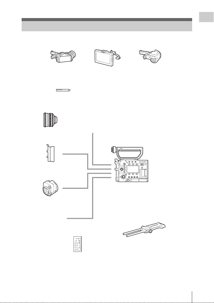
System Configuration
This section shows examples of the camera system configuration.
Overview
Viewfinder
DVF-L350
Lenses
PMW-F3K supplied lenses (35 mm/50 mm/85mm)
SCL-PK6/F, PK6/M (set of 6 lenses, 20 mm/25 mm/35 mm/50 mm/85 mm/135 mm)
SCL-PK3/F, PK3/M (set of 3 lenses, 20 mm/25 mm/135 mm)
SCL-P11X15
SCL-Z18X140
Lens mount
adapter
Mount adapter
LA-FZB1, LA-FZB2
Viewfinder
DVF-L700
Microphone
ECM-680S (EC-0.5X5F3M), ECM-678, ECM-674
PMW-F55, PMW-F5
Viewfinder
DVF-EL100
Optical 2K Filter
CBK-55F2K
Remote control unit
RM-B170, RM-B750, CBK-DCB01
USB wireless LAN module
IFU-WLM3 (supplied)
Shoulder adaptor
VCT-FSA5
Additional codec board
CBK-55PD
4K upgrade license (for PMW-F5)
CBKZ-55FX
System Configuration
9
Page 10
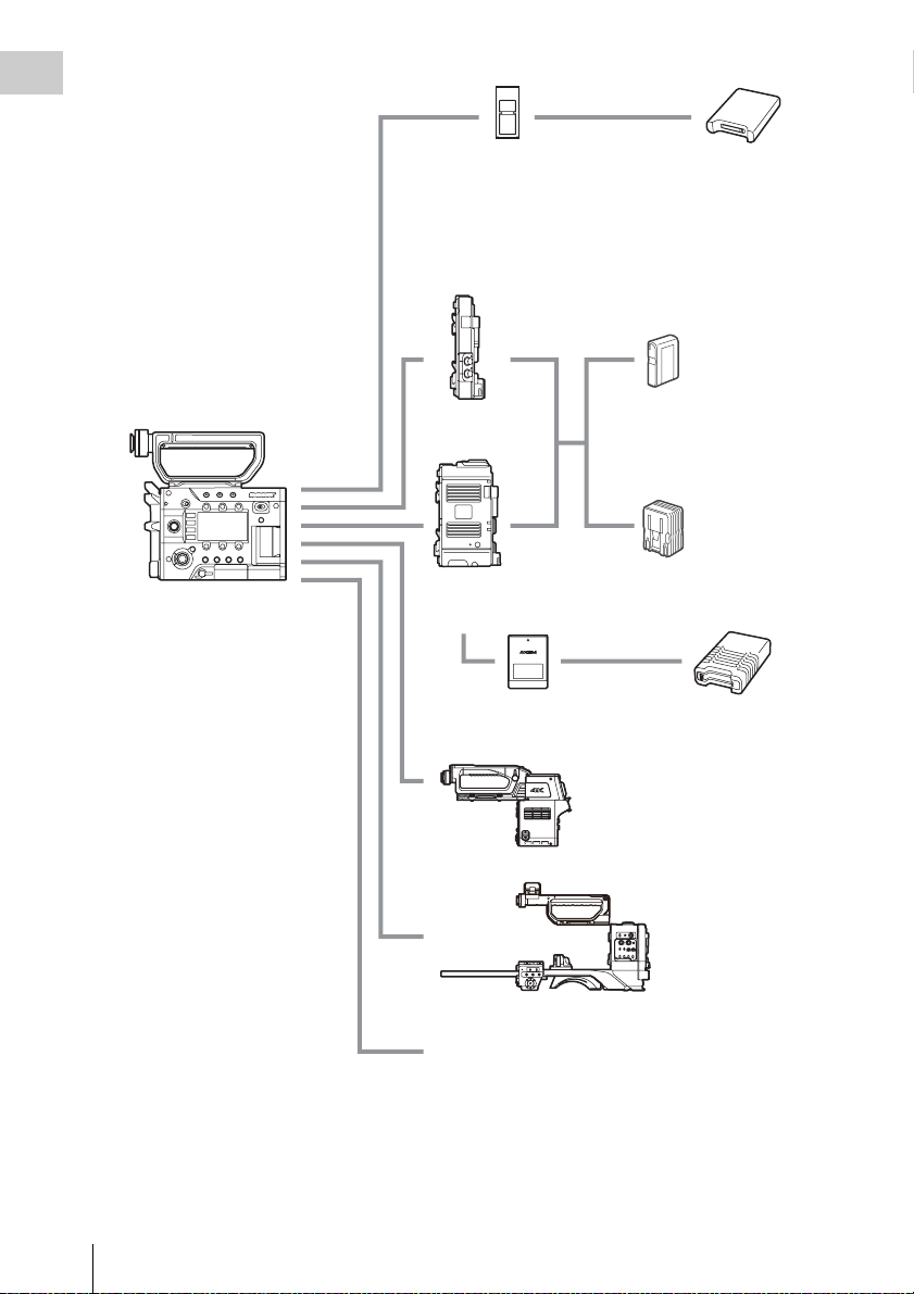
Overview
PMW-F55, PMW-F5
SxS memory card
SBP-128B, SBP-64A/B, SBP-32,
SBS-64G1A, SBS-32G1A
XQD memory card
QD-S64E, QD-S32E, QD-N64,
QD-G128A, QD-G64A, QD-G32A
(QDA-EX1 XQD ExpressCard adapter is required.)
Battery adaptor
Portable memory
recorder
AXS-R5
AXS memory card
AXS-512S24, AXS-A256S24,
AXS-A512S24, AXS-A1TS24
USB card reader
SBAC-US20
Battery pack
BP-FL75, BP-L80S
AC adaptor
AC-DN2B, AC-DN10
AXS memory card
reader
AXS-CR1
System Configuration
10
Camera system adaptor
CA4000
EFP style buildup kit
CBK-55BK
Monitor: BVM series, PVM series, LMD series
Page 11
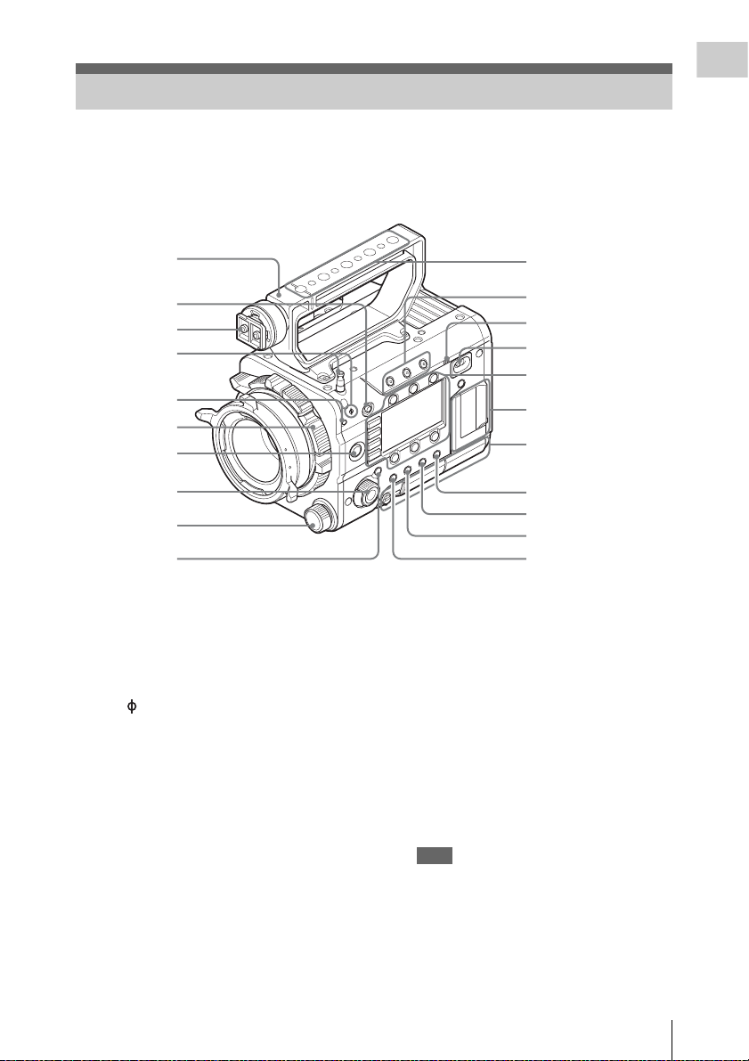
Location and Function of Parts
For functions and usage, see the pages in parentheses.
The following illustrations are with the battery adaptor (page 16) removed.
For removing the battery adaptor, see “Removing a battery pack” (page 23).
Overview
1
2
3
4
5
6
7
8
9
10
1. Handle
2. LOCK switch
Disables operations on the side operating panel.
3. Viewfinder shoe
4. Tape measure hook/Image sensor position
index
The mark and tape measure hook are on a
plane with the image sensor. To measure the
precise distance between the camcorder and the
subject, use this mark or tape measure hook as a
reference.
You can attach the end of a tape measure to the
hook, and measure the distance from the subject.
5. Flange focal length adjustment screw
(page 26)
6. Lens mount (page 25)
7. REC (recording start/stop) button/lamp
(page 40)
8. SEL/SET (select/set) dial (MENU dial)
(pages 51, 56)
Selects the item in the menu or changes the
setting value.
11
12
13
14
Sub display/Control
buttons block (page 14)
SxS memory card slot
block (page 14)
Right side connector
panel (page 14)
15
16
17
18
9. ND FILTER select switch
ND filters are available for keeping the
aperture in a proper range.
Select the ND filter by turning the ND
FILTER select switch while pulling it.
Clear: ND filter not used
1
/8ND
0.9:
1
/64ND
1.8:
10. CANCEL/BACK button (pages 51, 56)
11. Accessory mounting screw holes
Type of screw: 1/4-20UNC (× 4)
Type of screw: 3/8-16UNC (× 5)
Length of engagement: 9 mm
3
/8 inch) or less
(
Note
Do not apply excessive force to the mounted
accessory. It may damage the screw thread.
12. ASSIGN (assignable) 1/2/3 buttons (page
43)
13. Built-in speaker (page 40)
Location and Function of Parts
11
Page 12

14. Power switch
Overview
Set to the ON position (=) to turn the power on.
Set to the OFF position (1) to turn the power
off.
Notes
• This camcorder uses a small amount of standby
power even when the power switch is set to OFF.
Remove the battery pack if the camcorder will not
be used for a prolonged period.
• When removing the battery pack or the DC IN
power, be sure to first set the power switch to the
OFF position. Removing the battery pack or the
DC IN power while the camcorder is ON may
cause damage to the camcorder or the memory
card.
15. BRIGHTNESS button
Adjusts brightness of the sub display in 4 steps.
16. STATUS (status display on/off) button
Displays status screens on the viewfinder or
external video monitor.
Turn the MENU dial (page 11) to switch the
screens in sequence.
Tip
Items in [ ] are displayed when the CBK-55BK is
attached.
Camera status screen
Displays the electronic shutter settings or the
status of the lens.
Gain Amount of gain up (dB) or
Shutter Electronic shutter settings
Gamma Gamma category and curve
White White balance mode and
Zebra1 On/off and setting level of
Zebra2 On/off and setting level of
[Gain/El Switch
<L>]
[Gain/El Switch
<M>]
[Gain/El Switch
<H>]
Iris T value of iris
Focal Length Focal length (mm)
Focus Distance Focus distance (m/feet)
Depth Of Field Depth of field (m/feet)
Optical Filter Type of optical filter
sensitivity (ISO-EI)
(When “Shooting Mode” is
set to “Cine EI,” Gamma for
MLUT Off is displayed.)
setting
Zebra1
Zebra2
Setting level of the gain
switch L on the CBK-55BK
Setting level of the gain
switch M on the CBK-55BK
Setting level of the gain
switch H on the CBK-55BK
Audio status screen
Displays the input settings for each channel,
audio level meter, and wind filter setting.
Level Level meter
Source Input source
Reference Reference level setting
Wind Filter Wind filter setting
System status screen
Displays the video signal settings.
System Frequency
Rec Format Recording format that is
Picture Size Picture size that is recorded on
Rec Function Special recording that is set to
Gamma Gamma category that is
Imager Scan Imager reading mode
Picture Cache
Rec
MPEG2 Proxy On/off setting of MPEG2
Option Attached option
System frequency
recorded on the SxS memory
card
an SxS memory card
on, and its setting
recorded on the SxS memory
card
On/off setting of Picture
Cache Rec
proxy (PMW-F55 and PMWF5 + CBKZ-55FX)
Video output status screen
Displays the video output settings of SDI 1 to
SDI 4, HDMI, and test video output.
Picture size Output picture size
C.Space Output form
Freq Output rate
Gamma Gamma
Assignable button status screen
Displays the function that is assigned to each
ASSIGN button.
1 to 4 ([5] to [8]),
Lens RET
Menu Dial
Assign
Functions that are assigned to
the Assign 1 to 4 ([5] to [8])
buttons and RET button on a
lens
Functions that are assigned to
the Menu dial
Battery status screen
Displays information of the battery or DC IN
power.
Detected Battery Battery type
Remaining Remaining charge level (%)
Charge Count Number of times that the
Capacity Remaining capacity (Ah)
battery is charged
Location and Function of Parts
12
Page 13
Vo lt ag e Vol ta ge (V )
Manufacture
Date
Power Source Power source
Supplied Voltage Supplied voltage
Media status screen
Displays the remaining space, available
recording time, and estimated service life of the
recording media (SxS memory card A/SxS
memory card B/SD card/AXS memory).
Manufacture date of the
battery
1
Air outlet
2
3
4
5
Protect
information
Remaining
Life
Remaining space and
available recording time
Estimated service life
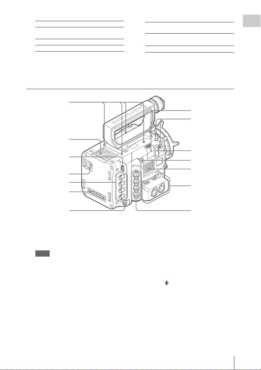
17. OPTION button (page 48)
18. MENU (menu display on/off) button (page
56)
7
8
9
10
Air inlet
Audio connector
panel (page 15)
Overview
6
1. Accessory mounting screw holes
Type of screw: 1/4-20UNC (× 4)
Length of engagement: 9 mm
3
/8 inch) or less
(
Notes
• Do not apply excessive force to the mounted
accessory. It may damage the screw thread.
• When attaching an accessory, do not cover the air
inlet or air outlet.
2. HDMI OUT connector (page 96)
3. DC IN connector (page 24)
4. SDI OUT 1 to 4 (serial digital output)
connectors (BNC type) (page 96)
5. Mounting terminal for an expansion unit
(pages 23, 33)
6. REMOTE (remote control) connector (8-
pin)
Left side connector
panel (page 16)
Connect an external device such as a remote
control unit.
7. USB wireless LAN module retracting part
(page 35)
Connecting the supplied IFU-WLM3 USB
wireless LAN module allows communication
with wireless LAN devices.
8. Tape measure hook/Image sensor position
index
The mark and tape measure hook are on a
plane with the image sensor. To measure the
precise distance between the camcorder and the
subject, use this mark or tape measure hook as a
reference.
You can attach the end of a tape measure to the
hook, and measure the distance from the subject.
9. VF (viewfinder output) connector (page
26)
10. ASSIGN 4 (assignable 4) button (page 43)
Location and Function of Parts
13
Page 14
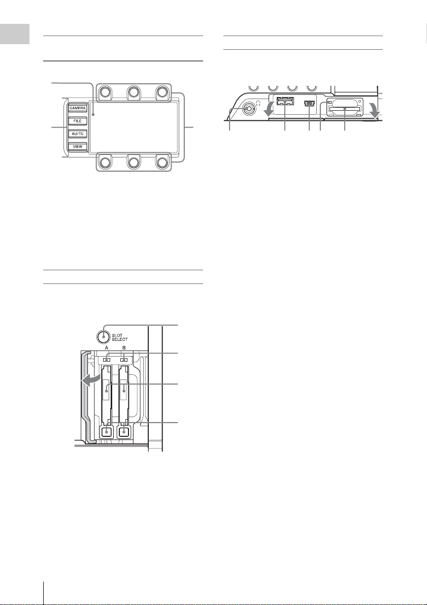
Sub display/Control buttons block (page
Overview
51)
1
Right side connector panel
The USB connector and SD card slot are located
behind the cover.
23
Open the
cover.
2
4 531
1. Headphones connector (stereo mini jack)
(page 40)
1. Sub display
2. Function buttons
• CAMERA button
• FILE button
• AU/TC (audio/time code) button
• VIEW button
2. USB connector (A)
3. USB connector (Mini B)
4. ACCESS (SD card access) lamp (page 32)
5. SD card slot (page 32)
3. Item button
SxS memory card slot block (page 29)
The SxS memory card slots are located behind the
cover.
1
2
Open the
cover.
3
Open the
cover.
1. SLOT SELECT (SxS memory card select)
button
2. ACCESS (SxS memory card access) lamps
3. SxS memory card slots
4. EJECT (SxS memory card eject) buttons
Location and Function of Parts
14
4
Page 15
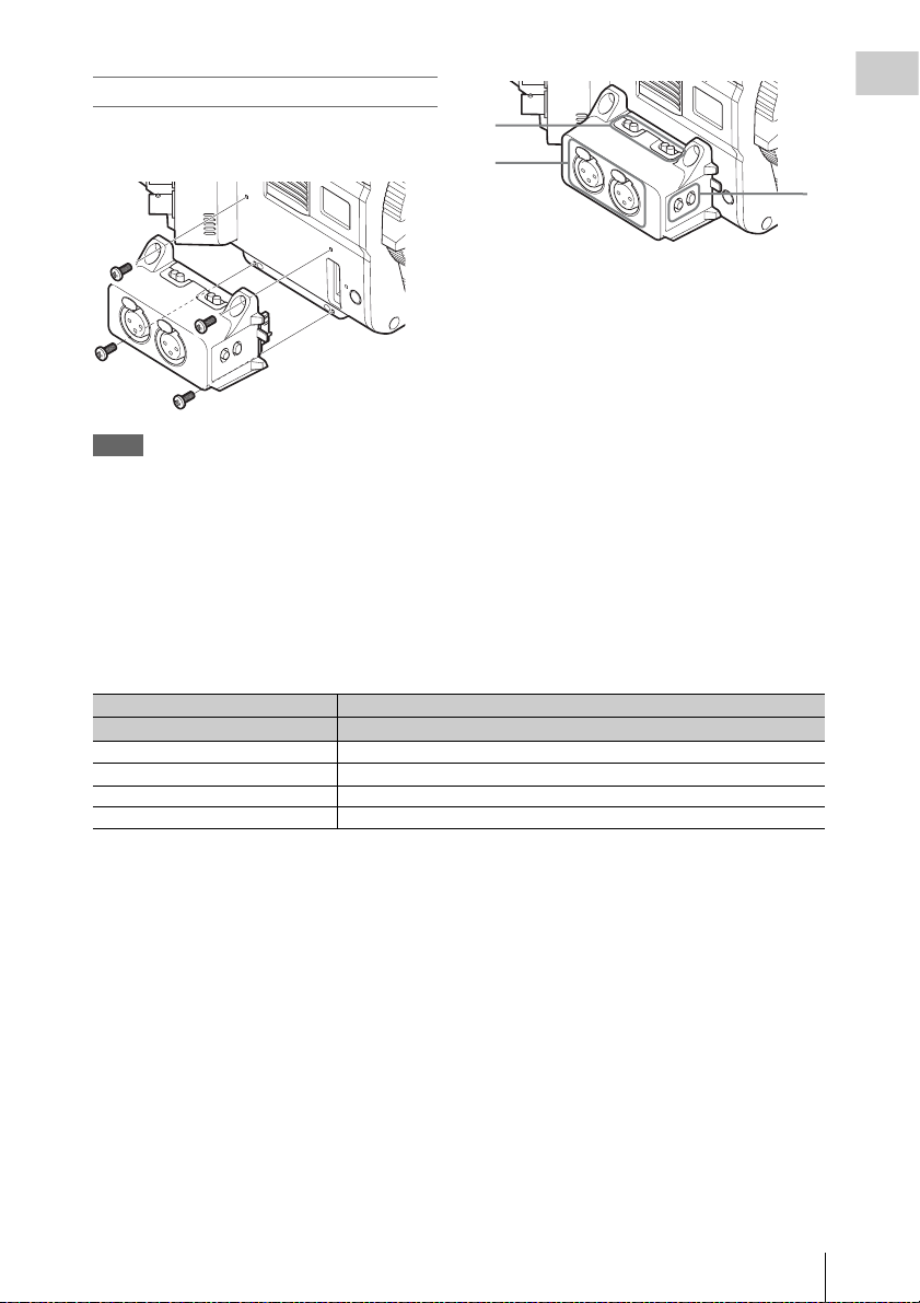
Audio connector panel
Attach the supplied audio connector panel as
follows.
1
2
1. AUDIO IN CH1/AUDIO IN CH2
(external audio input selection) switches
Switch input signal (external microphone,
external audio device, etc.).
LINE: Line input audio equipment
AES/EBU: AES/EBU format audio signal
MIC: Microphone input
Notes
• Attach/remove the audio connector panel while the
camcorder is turned off.
• When attaching the audio connector panel, make sure
not to catch the cap.
• When removing the audio connector panel, pull it
away slowly from the body of the camcorder, as shown
in the diagram above.
• Applying excessive force to remove the audio
connector panel may damage it.
Settings of the AUDIO IN CH1/AUDIO IN CH2 switch and recorded channels are as below.
AUDIO IN CH1/CH2 switch Recorded channel
CH-1 CH-2 CH-1 CH-2 CH-3 CH-4
LINE/MIC LINE/MIC LINE1/MIC1 LINE2/MIC2 No sound No sound
AES/EBU LINE/MIC AES/EBU1-1 AES/EBU1-2 No sound No sound
LINE/MIC AES/EBU LINE1/MIC1 No sound AES/EBU2-1 AES/EBU2-2
AES/EBU AES/EBU AES/EBU1-1 AES/EBU1-2 AES/EBU2-1 AES/EBU2-2
2. AUDIO IN (CH-1, CH-1/2) /AUDIO IN
(CH-2, CH-3/4) connectors
Input external microphone or audio
equipment signals.
3. CH1 MIC +48V/OFF, CH2 MIC +48V/
OFF (external microphone input
selection) switches
Supply phantom power (48 V) to the external
microphone when you set this switch to
“MIC +48V.”
Overview
3
LINE1/MIC1: LINE or MIC signal that is input to CH-1
LINE2/MIC2: LINE or MIC signal that is input to CH-2
AES/EBU1-x: Channel x signal of the AES/EBU signal that is input to CH-1
AES/EBU2-x: Channel x signal of the AES/EBU signal that is input to CH-2
Location and Function of Parts
15
Page 16
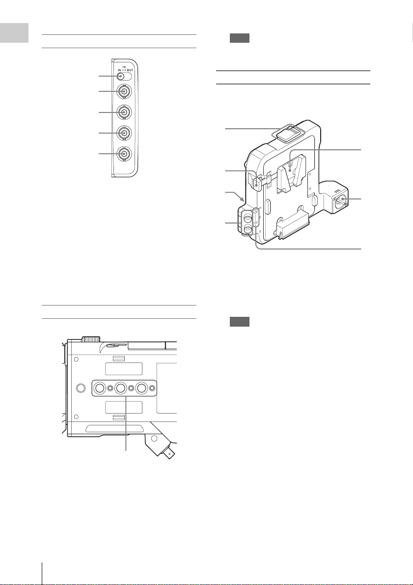
Left side connector panel
Overview
Note
Do not apply excessive force to the mounted
accessory. It may damage the screw thread.
1
2
3
4
5
1. TC IN/OUT (timecode input/output
selection) switch (page 98)
2. TC (timecode input/output) connector
(BNC type) (page 98)
3. GENLOCK IN connector (BNC type)
(page 98)
4. TEST OUT (analog video output)
connector (BNC type) (page 96)
5. SHUTTER connector (BNC type)
Not used for this version
.
Bottom
Battery adaptor
For attaching/removing the battery adaptor, see
“Using a Battery Pack” (page 23).
1
2
3
4
1. Release button/ejection lever
2. Battery release lever
3. Expansion IF connector
4. DC OUT 1/2 connector
Note
When connecting a device, use one with current
consumption of 1.8 A or less.
5. Battery pack attaching part
6. DC IN connector (page 24)
7. DC OUT overcurrent indicator
Lights when the overcurrent protection
activates.
In this case, disconnect any peripheral device
from a DC OUT connector whose indicator is
lit, then restart the PMW-F55/F5.
5
6
7
1. Accessory mounting screw holes
Type of screw: 1/4-20UNC (× 3)
Type of screw: 3/8-16UNC (× 3)
Length of engagement: 9 mm
3
/8 inch) or less
(
Location and Function of Parts
16
1
Page 17
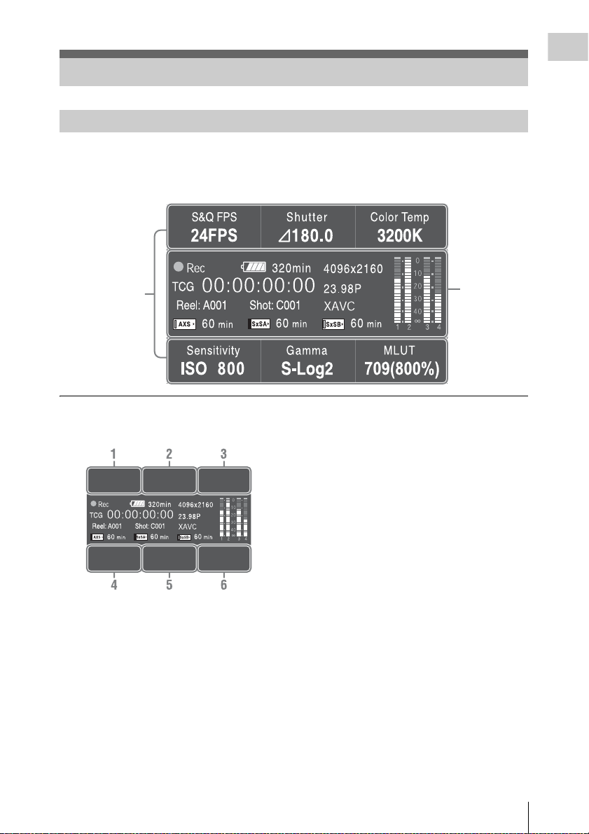
On-Screen Indications
Sub Display Screen
When turning on the camcorder, the sub display appears and you can check the status of the camcorder
and set the basic items.
The screen is switched by pressing the function button on the left of the sub display (page 14).
Item name/
Setting value/
Function display
screen
Status screen
Overview
Item name/Setting value/Function display
screen
CAMERA-1 (page 52)
1. S&Q FPS
Displays and sets Slow & Quick Motion/
Frame Rate.
2. Shutter
Displays and sets shutter speed/angle.
3. Color Temp
Displays and sets color temperature.
4. Sensitivity/Gain/Exposure Index
Displays and sets sensitivity/gain (ISO/dB/
EI).
5. Gamma/High Latitude
Displays and sets gamma category.
(When “Shooting Mode” (page 90) is set to
“Cine EI,” “High Latitude” is displayed.)
6. MLUT
Displays and sets monitor LUT/Look Profile.
The MLUT indication appears only when
“Shooting Mode” (page 90) is set to “Cine
EI.”
CAMERA-2 (page 53)
1. Color Bars
Turns the color bars on/off.
2. Auto White
Performs the auto white balance function.
3. Auto Black
Performs the auto black balance function.
4. Sub&HDMI
Turns the Monitor LUT of SDI (Sub) and
HDMI output on/off.
5. Viewfinder
Turns the Monitor LUT of viewfinder output
on/off.
On-Screen Indications
17
Page 18

6. SDI (Sub) Disp.
Overview
Turns the function that outputs the character
information to the SDI (Sub) output on/off.
FILE-1 (page 53)
1. to 6. All File Load 1 to 6
Loads the All file (1 to 6) from the SD card.
FILE-2 (page 53)
1. to 6. Scene Recall 1 to 5/Standard
Loads the Scene file (1 to 5, or Standard)
from the internal memory.
FILE-3 (page 54)
1. to 6. Lens Recall 1 to 6
Loads the Lens file (1 to 6) from the internal
memory.
AU/TC-1 (page 54)
1. MIC CH1 Ref
Displays/sets the reference input level for
MIC CH1.
2. CH1 Input
Sets Auto/Manual for the recording level of
CH1, and displays/sets the level for Manual
setting.
3. CH1 Select
Displays the input source for CH1.
4. MIC CH2 Ref
Displays/sets the reference input level for
MIC CH2.
5. CH2 Input
Sets Auto/Manual for the recording level of
CH2, and displays/sets the level for Manual
setting.
6. CH2 Select
Displays the input source for CH2.
AU/TC-2 (page 55)
3. Monitor CH
Displays/sets the audio channel that is output
to the headphones and speaker.
5. Monitor Level
Displays/sets the monitor volume that is
output to the headphones and speaker.
AU/TC-3 (page 55)
1. Display
Displays/sets the time data.
2. Reset
Resets the timecode and counter.
3. Set
Sets the timecode.
4. Mode
Sets the timecode mode.
5. Run
Sets the condition for the timecode.
6. TC Source
Displays the external lock status for the
timecode.
VIEW-1
1. F Rev m
Fast reverse
2. Play/Pause BX
Play/pause
3. F Fwd M
Fast forward
4. Prev .
Previous clip jump
5. Stop x
Stop
6. Next >
Clip directional jump
VIEW-2
1. Thumbnail
Displays or cancels the display of the
thumbnail screen.
2. Up M
Moves the cursor up.
3. Set
Confirms the selected item.
4. Left <
Moves the cursor to the left.
5. Down m
Moves the cursor down.
6. Right ,
Moves the cursor to the right.
On-Screen Indications
18
Page 19
Status screen
Overview
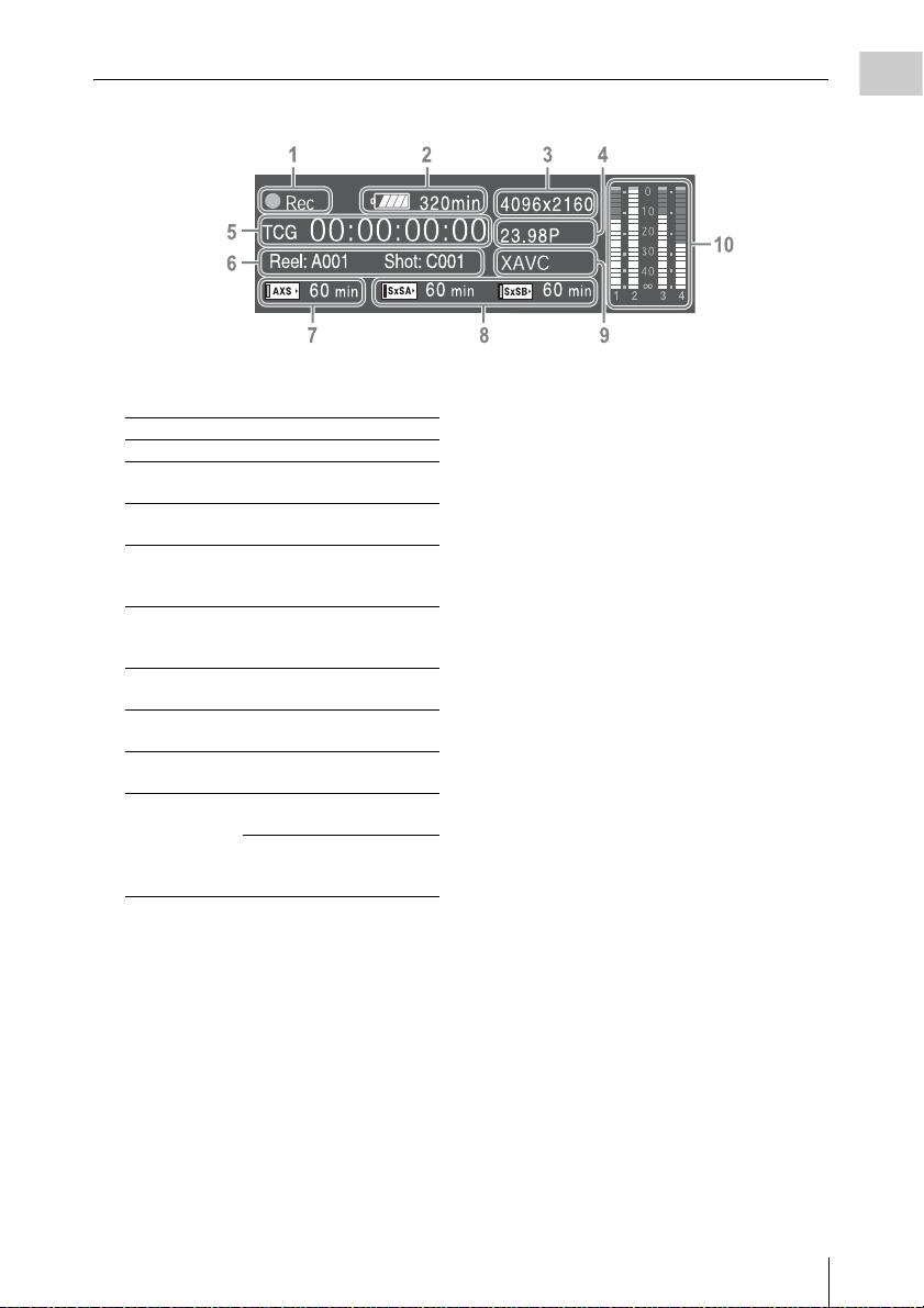
1. Special recording/operation status
indication
zRec Recording in progress
Stby Standby for recording
zS&Q Rec Slow & Quick Motion
recording in progress
S&Q Stby Standby for Slow & Quick
Motion recording
zHFR Rec Slow & Quick Motion and Hi
Frame Rate mode recording in
progress
HFR Stby Standby for Slow & Quick
Motion and Hi Frame Rate
mode recording
zInt Rec Recording in progress in
Interval Rec mode
Int Stby Standby for Interval Rec
recording
zInt Stby Waiting for Interval Rec
picture capturing
zCache z lights in green: Standby for
Picture Cache Rec mode
z lights in red: Recording in
progress in Picture Cache Rec
mode
2. Battery remaining charge/DC IN voltage
indication (page 24)
3. Recording format (picture size) indication
(page 28)
Displays the picture size that is recorded on
an SxS memory card.
4. System frequency and scan method
indication (page 27)
5. Time data indication (page 43)
6. Clip name indication (page 85)
While recording:
Displays “Clip: clip name” when “Mode” in
“Clip Naming” of the Media menu is set to
“Title,” or “Reel: Camera ID + Reel
Number” and “Shot: Camera Position + Shot
Number” when “Mode” in “Clip Naming” of
the Media menu is set to “Cam ID + Reel#.”
While playing/displaying the thumbnail
screen:
Displays “Clip: clip name.”
7. AXS memory status/remaining space
indication (page 34)
8. A/B slot media status/remaining space
indication (page 31)
9. Recording format (codec) indication (page
28)
Displays the format that is recorded on an
SxS memory card.
10. Audio level meter (4CH)
On-Screen Indications
19
Page 20
Viewfinder Screen
Overview
While recording, standing by to record, or playback, the statuses and settings of this unit are superimposed
on the viewfinder screen.
The statuses and settings of this unit can be turned on/off using the setup menu or by the assignable button.
The statuses and settings of this unit can be independently turned on/off (page 82).
To turn on/off on the setup menu
Turn on/off the statuses and settings of this unit on “Setting” in “Display On/Off” (page 82) of the VF
menu.
To turn on/off by the assignable button
Assign “Display” to one of the assignable buttons (page 43). You can turn on/off the statuses and settings
of this unit by pressing the assignable button.
Tip
When using the 1.3× or 2× anamorphic lens, set “Aspect” in “VF Setting” (page 80) of the VF menu to “Anamo ×1.3”
or “Anamo ×2” to display the normal image without distortion on the viewfinder screen.
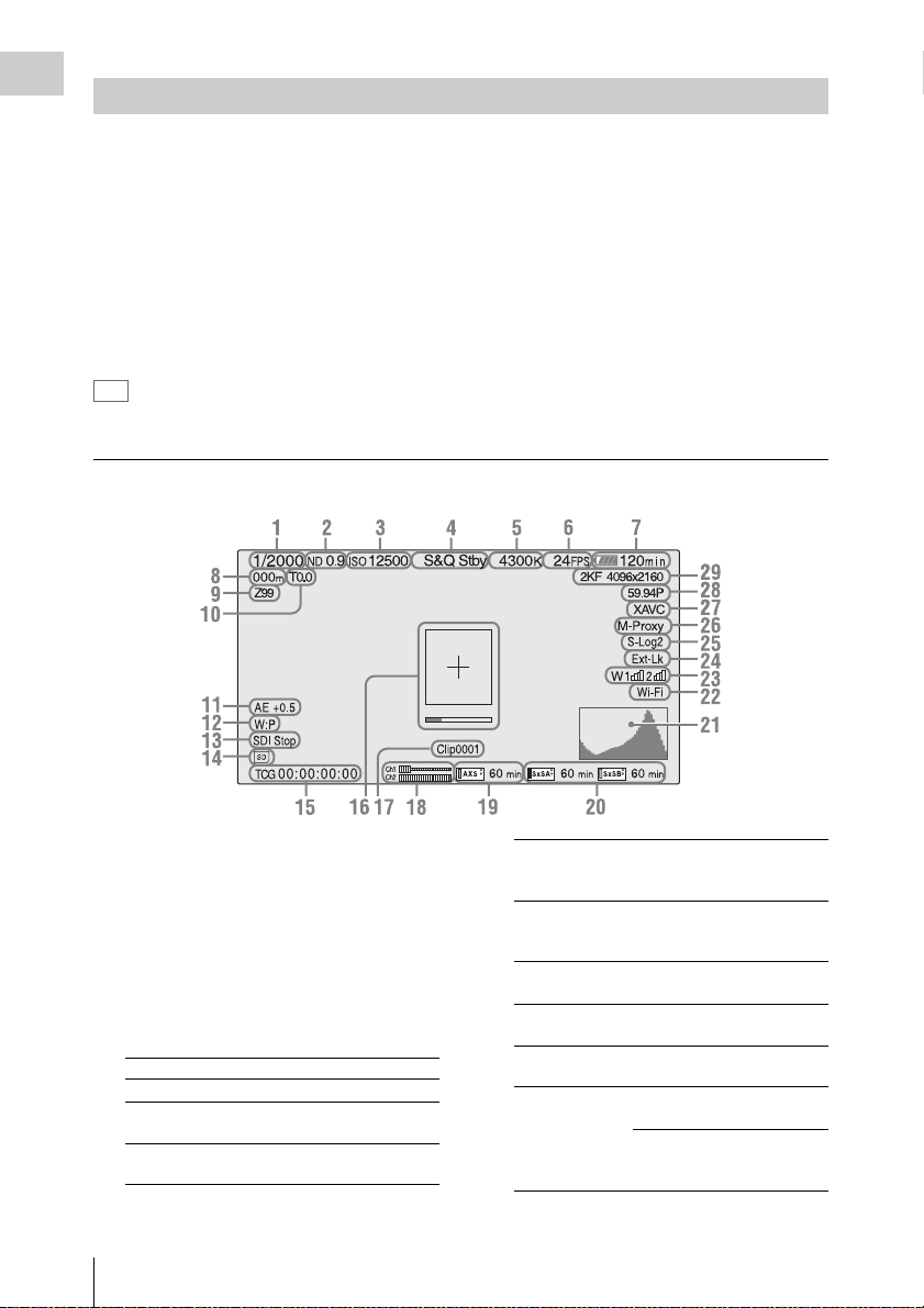
Information displayed on the screen while recording
1. Shutter mode/shutter speed indication
(page 64)
2. ND filter indication (page 11)
3. Gain indication (page 61)
Displayed as the EI value when “Shooting
Mode” in “Base Setting” (page 90) of the
System menu is set to “Cine EI.”
4. Special recording/operation status
indication
zRec Recording in progress
Stby Standby for recording
zS&Q Rec Slow & Quick Motion
S&Q Stby Standby for Slow & Quick
On-Screen Indications
20
recording in progress
Motion recording
zHFR Rec Slow & Quick Motion and Hi
Frame Rate mode recording in
progress
HFR Stby Standby for Slow & Quick
Motion and Hi Frame Rate
mode recording
zInt Rec Recording in progress in
Interval Rec mode
Int Stby Standby for Interval Rec
recording
zInt Stby Waiting for Interval Rec
picture capturing
zCache z lights in green: Standby for
Picture Cache Rec mode
z lights in red: Recording in
progress in Picture Cache Rec
mode
Page 21

5. Color temperature indications (page 59)
6.
S&Q motion frame rate/Interval Rec
indication (
Displays the interval time setting or time until
the next recording, during Interval Rec.
pages 66, 84)
7. Battery remaining charge/DC IN voltage
indication (page 24)
8. Focus position indication
Displays focus position (only when a lens that is
compatible with the focus setting display
function is attached).
9. Zoom position indication
Displays zoom position in the range of 0 (wide
position) to 99 (tele position) (only when a lens
that is compatible with the zoom setting display
function is attached).
10. Iris position indication
Displays iris position (only when a lens that is
compatible with the iris setting display function
is attached).
11. Auto iris level indication
Displayed when “Level” in “Auto Exposure”
(page 65) of the Camera menu is set to a value
other than “±0.”
12. White balance mode indication (page 59)
W:P Preset mode
W:M Memory mode
13. Control status of SDI output indication
(page 77)
14. SD card indication
15. Time data indication (page 43)
16. Focus assist indication (page 82)
Displays the area that detects the focus status
(“Focus Area Marker”) and level bar that
indicates focus status in the area (“Focus Assist
Indicator”).
17. Clip name indication (page 41)
18. Audio level meter
19. AXS memory status/remaining space
indication (page 34)
When the left side of the icon is orange,
recording is possible.
When the green lamp on the upper right of the
icon lights, playback is possible.
20. A/B slot media status/remaining space
indication (page 31)
When the left side of the icon is orange,
recording is possible.
When the green lamp on the upper right of the
icon lights, playback is possible.
21. Video signal indication (page 82)
Displays the waveform, vector scope, and
histogram.
22. Wi-Fi connection status indication (page
35)
Appears when “Wi-Fi” (page 94) is set to
“Enable.”
23. Wireless receiver reception level
When an UHF portable tuner is installed to the
buildup kit CBK-55BK (optional) attached to
the camcorder, “W” appears together with four
segment reception level indicators for each of
the channels (1 to 2) that can be used by the
tuner. The indications are as follows.
In the normal situati on: The number of segments
indicates the strength of the signal level.
Muting: The number of transflective segments
indicates the strength of the signal level.
Reception level over peak: “P” is displayed
instead of the indicators.*
Tuner battery is low: The channel number and
indicator of the corresponding channel flash.*
* For DWR-S02D only
24. Timecode external lock indication
When the unit is locked to the timecode of an
external device, “Ext-Lk” appears.
25. Gamma/Monitor LUT indication (pages
68, 78)
Displays the gamma setting value. When
“Shooting Mode” (page 90) is set to “Cine EI,”
gamma for a picture that is recorded on an SxS
memory card or the Monitor LUT setting
appears.
26. Simultaneous recording status indication
(page 45)
M-Proxy: Displayed when the function of
simultaneous recording on one memory card is
effective.
27. Recording format (codec) indication (page
28)
Displays the format that is recorded on an
SxS memory card.
28. System frequency and scan method
indication (page 27)
Overview
On-Screen Indications
21
Page 22
29. Recording format (picture size) indication
Overview
(page 28)
Displays the picture size that is recorded on
an SxS memory card.
Displays the imager scan mode (2KF: 2K
Full, 2KC: 2K Center) on the left side of the
picture size.
Displays imager scan mode only when
recording only RAW format.
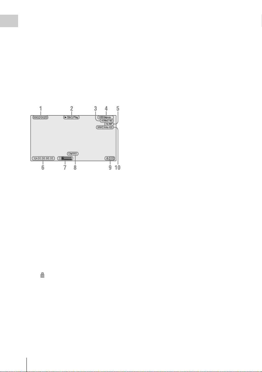
Information displayed on the playback screen
The following information is superimposed on
the playback picture.
1. Clip no./total number of clips
2. Playback mode
3. Playback format (picture size)
4. Battery charge remaining/DC IN voltage
5. Playback format (frame rate)
6. Time data
You can switch between timecode and duration
by using “TC Display” (page 83) in the TC/UB
menu.
7. Audio levels
The audio levels for the recording are displayed.
8. Clip name
9. Media
A mark appears to the left if the memory
card is write-protected.
10. Playback format (codec)
On-Screen Indications
22
Page 23
Preparations
Power Supply
You can use a battery pack or AC power via an
AC adaptor.
For safety, use only the Sony battery packs and
AC adaptors listed below:
Lithium-ion Battery Pack
BP-FL75
BP-L80S
AC Adaptor
AC-DN2B
AC-DN10
Using a Battery Pack
Attaching a battery pack
1 Attach the battery adaptor (supplied) to
the camcorder.
Press the release button (1) of the battery
adaptor to pop up the ejection lever, then raise
the ejection lever (2).
Battery pack
Battery
release
lever
attaching part
Insert the projection of the battery adaptor into
the slot on the rear of the camcorder (1), then
lower the ejection lever (2).
Notes
• Before attaching the battery adaptor, make sure
that the ejection lever is raised.
• Before lowering the ejection lever, make sure that
the four hooks are attached securely. If the four
hooks are not attached securely, it may cause the
connection to be poor or damage the camcorder
and battery adaptor.
2 Attach a battery pack to the battery
adaptor.
Insert the battery pack into the battery pack
attaching part of the battery adaptor, then slide
the battery pack down to lock it in place.
Notes
• Before use, charge the battery pack with the battery
charger.
• A warm battery pack immediately after use may not be
able to be fully recharged.
Preparations
Removing a battery pack
Unlock the battery pack by sliding it up while
pressing the battery release lever, then remove it.
Press the release button and raise the ejection
lever, then remove the battery adaptor by pulling
it out while sliding upward.
Note
Remove the battery adaptor while supporting the
camcorder by hand.
Power Supply
23
Page 24
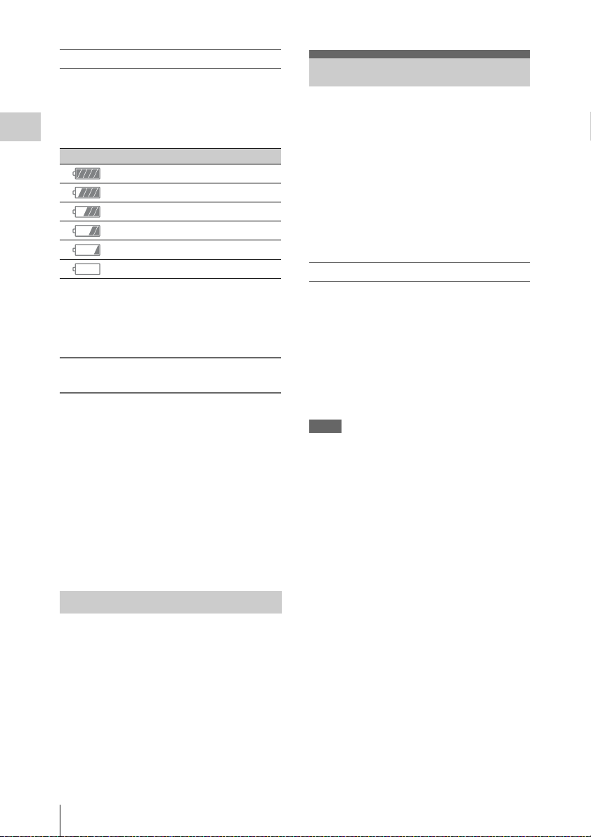
Checking remaining battery charge
When recording or playback is in progress on the
battery pack, an icon to show the current battery
remaining time and battery voltage are displayed
on the sub display screen (page 17) and
viewfinder screen (page 20).
Preparations
Icon Remaining charge
100% to 91%
90% to 71%
70% to 51%
50% to 31%
30% to 11%
10% to 0%
The camcorder indicates the remaining usage
time in minutes by calculating the available time
with the battery pack if operation is continued at
the current rate of power consumption.
If the remaining battery charge becomes
low
If the remaining battery charge decreases to a
certain level during operation, a low-battery
message, flashing of the REC lamp, and a beep
sound will warn you.
If the remaining charge further decreases to a
level at which operation cannot be continued, a
battery-empty message appears.
Replace the battery pack with one that is fully
charged.
To change the message levels
These settings can be changed with “Battery
Alarm” (page 93) in the System menu.
Setting the Clock
When you turn the camcorder on for the first time
after purchasing or replacing the backup battery,
the Initial Setting display appears on the
viewfinder screen.
Set the date and time of the built-in clock, using
this display.
Time Zone
The value shows the time difference from UTC
(Coordinated Universal Time).
Change the setting if needed.
Setting the time and date
Turn the MENU dial (page 11) to move the
cursor, then press the MENU dial to set each
menu item. When you press the MENU dial when
the cursor is on “Finish,” the setting display
disappears, the clock setting is completed.
After the setting display disappears, “Clock Set”
(page 94) in the System menu can be used to set
“Time Zone” and date/time.
Notes
• If the clock setting is cleared because the backup
battery fully discharged when no power was supplied
(no battery pack and no DC IN connection), the Initial
Setting display will be displayed when you next turn
the camcorder on.
• While the Initial Setting display is shown, no other
operation, except turning the power off, is permitted
until you finish the setting for this display.
Using AC Power (DC IN Power)
The camcorder works with AC power by using
the AC adaptor AC-DN2B/AC-DN10 (optional)
and DC cable CCDD-X2 (optional).
Setting the Clock
24
Page 25
Attaching Optional Devices
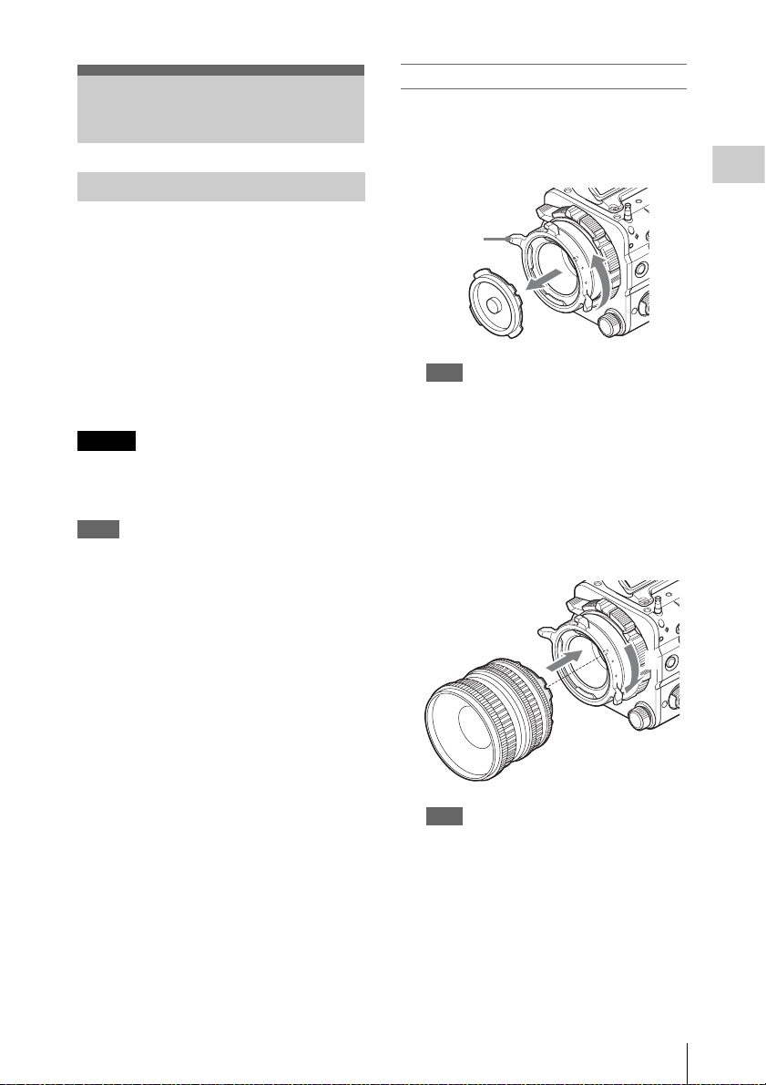
Attaching a PL mount lens
1 Remove the mount cover from the lens
mount by turning the PL mount lever
counterclockwise.
Attaching a Lens
Recommended lenses
PMW-F3K supplied lenses (35 mm/50 mm/85
mm)
SCL-PK6/F, SCL-PK6/M (set of 6 lenses, 20
mm/25 mm/35 mm/50 mm/85 mm/135 mm)
SCL-PK3/F, SCL-PK3/M (set of 3 lenses, 20
mm/25 mm/135 mm)
SCL-P11X15
SCL-Z18X140
For details about available lenses for the camcorder,
contact a Sony service representative.
Caution
Do not leave the lens facing the sun. Direct
sunlight can enter through the lens, be focused in
the camcorder, and cause fire.
Notes
• Attach/remove a lens while the camcorder is turned
off.
• A lens is a precision part. Do not place the lens directly
with the mount part down. Attach the cover supplied
with the lens.
• The lens interface of the camcorder is set to “Type C,”
to correspond with the lens that is supplied with the
PMW-F3K, SCL-P11X15, and lenses with a Cooketype connector. When using a lens with an ARRI-type
connector, set “Lens interface” (page 67) in the
Camera menu to “Type A.” Set to “Off” for SCL-PK6,
SCL-PK3, or other lenses. If this setting is not correct,
an alert message appears when the camcorder is turned
on after attaching the lens.
PL mount
lever
Note
Turn the PL mount lever counterclockwise to the
stopper position.
2 Insert the lens into the lens mount by
matching the concave part of the lens to
the locating pin o n the upper right of the
lens mount.
3 Fix the lens by turning the PL mount
lever clockwise while holding the lens.
2
3
Preparations
Note
Do not turn the lens when attaching the PL mount
lens. It may cause damage to the hot shoe pin.
Attaching Optional Devices
25
Page 26

To attach an ARRI* LDS lens or Cooke/i lens
Match the contact of the lens to the hot shoe of the
camcorder.
Hot shoe for the Cooke/i lens
Preparations
Removing a lens
Remove a lens with the following steps.
1 Turn the PL mount lever
counterclockwise while holding the lens
from underneath.
2 Pull the lens forward.
Note
If another lens will not be attached soon, fit the concave
part of the mount cover, then fix the mount cover by
turning the PL mount lever clockwise.
Hot shoe for the ARRI LDS lens
* ARRI Group
Attaching other than a PL mount lens
When using an FZ mount lens or B4 lens by
attaching an optional LA-FZB1/FZB2 mount
adapter, attach it after removing the mount
adapter by turning the lens mount
counterclockwise.
Adjusting a flange focal length
You need to adjust the flange focal length
(distance from the mounting flange to the film
plane) for the following cases.
• When a lens is attached for the first time.
• When a lens is changed.
• When focus is not achieved for either tele or
wide angle while using a zoom lens.
You can adjust the flange focal length by turning
the screw for the flange focal length (page 11).
Use a hex key (7/64) for adjusting.
When turning the screw to the left, the flange
focal length becomes long. When turning the
screw to the right, the flange focal length
becomes short. Turn the screw slowly.
Notes
• The camcorder will not work if the screw for the flange
focal length is turned too much. Stop tur ning the screw
when the amount of the flange focal length no longer
changes. Approximate limit for turning the screw is 7
rotations to the right/left.
• Use a hex key of the specified size. Otherwise, the
screw head may be damaged and you may be unable to
turn the screw.
Selecting the lens file
By storing the adjustment value of the attached
lens as a file, you can easily perform adjustment
for the lens by loading the file.
Load the file in “Lens File” (page 88) of the File
menu.
Controlling zoom and focus from the
external device
You can control zoom and focus from the
optional CBK-DCB01 by connecting the CBKDCB01 to the REMOTE connector (page 13)
when using Sony lens SCL-Z18X140.
Note
When connecting the CBK-DCB01 to the REMOTE
connector independently, set “RM Common Memory” in
“Camera Config” (page 89) of the Maintenance menu to
“On.”
For details regarding CBK-DCB01 that can be used
with the camcorder, contact a Sony service
representative.
Attaching a Viewfinder
Available viewfinders for the camcorder
• DVF-L350: LCD color viewfinder
• DVF-L700: LCD color viewfinder
• DVF-EL100: OELD color viewfinder
Caution
Do not leave the camcorder with the eyepiece of
the viewfinder facing the sun. Direct sunlight can
enter through the eyepiece, be focused in the
viewfinder, and cause fire.
Attaching Optional Devices
26
Page 27
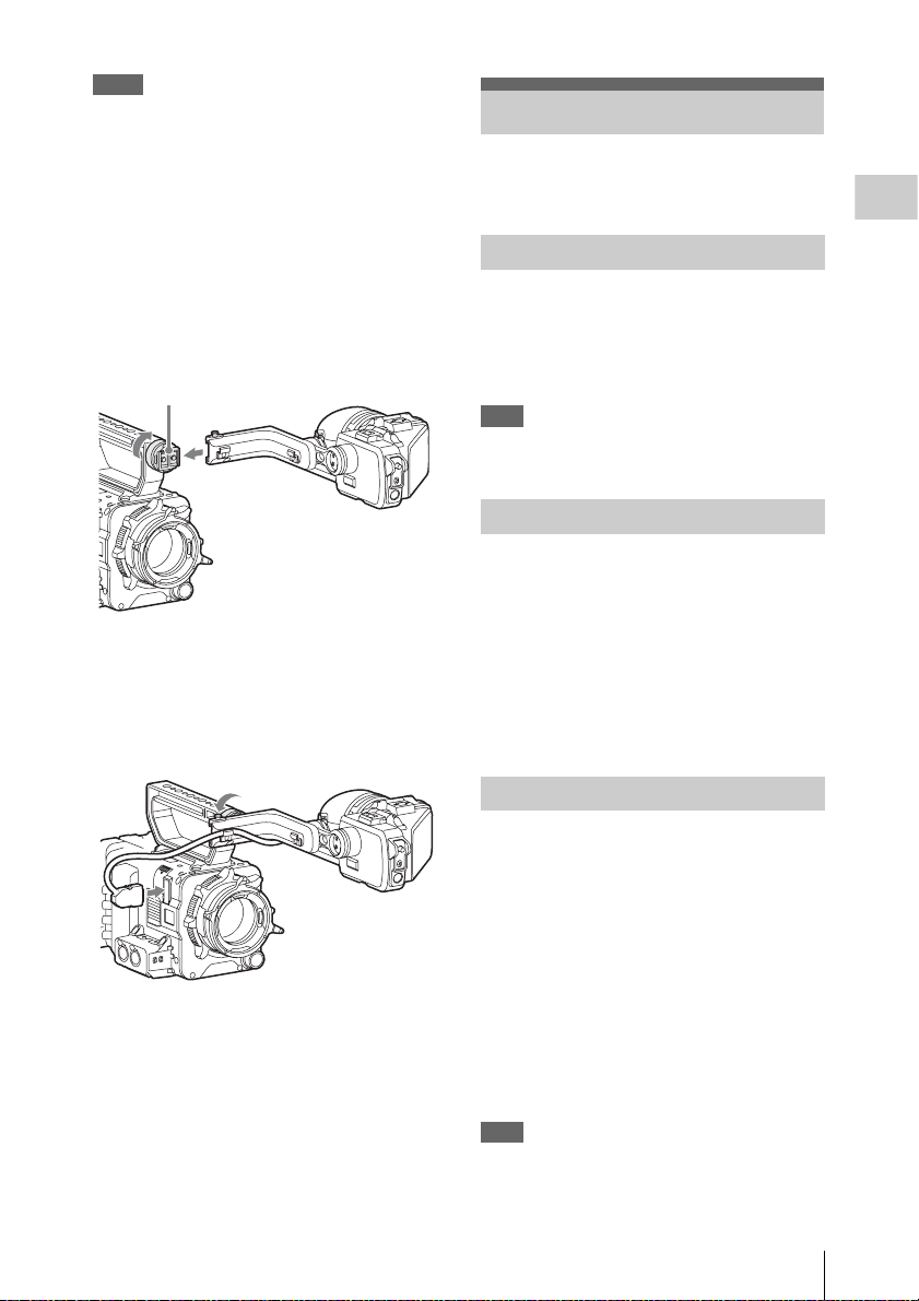
Notes
• Attach/remove the viewfinder while the camcorder is
turned off.
• When using the camcorder with the DVF-L700
attached, turn the camcorder on while the POWER
switch of the DVF-L700 is set to ON.
For details about attaching the viewfinder, refer to
the operating instructions of the viewfinder.
1 Loosen the fixing ring of the viewfinder
shoe, align the slot of the viewfinder,
then attach the viewfinder by sliding it
horizontally.
Viewfinder shoe
2 Tighten the fixing ring after
determining the left and right position
of the viewfinder, then connect the
viewfinder cable to the VF connector of
the camcorder.
Setting the Basic Action
Before recording, make the basic settings, as
required.
Preparations
System Frequency
Switch by setting “Frequency” in “System
Setting” (page 90) of the System menu.
After switching this setting, the camcorder will
automatically restart, depending on the setting
value.
Note
The system frequency setting cannot be changed during
recording or playback.
Shooting Mode
You can switch between the “Cine EI” mode
(allows you to use the camcorder as a film
camera, where the movie is edited postproduction, rather than at the time of shooting),
and the “Custom” mode (allows you to edit
pictures as you make the movie, by accessing all
the setting items).
Switch the mode by using “Shooting Mode” in
“Base Setting” (page 90) of the System menu.
To remove the viewfinder
Loosen the fixing ring for the viewfinder, raise
the stopper, then remove the viewfinder by
sliding it in the reverse direction for when
attaching.
Main Recorded Signal
Set the predominant signal format to be used.
Set the format by using “Main Operation” in
“Base Setting” (page 90) of the System menu.
The RAW signal is recorded on the AXR-R5
attached to the camcorder, and the YPbPr or RGB
signal is recorded on the SxS memory card in the
camcorder. Since the RGB signal is output from
the SDI 1/2 connector of the camcorder, record it
on an external device such as SR-R1.
Select the format from YPbPr/RGB/RAW when
“Shooting Mode” is set to “Cine EI,” and from
YPbPr/RGB when “Shooting Mode” is set to
“Custom.”
Note
The RAW signal can be selected only when attaching the
AXS-R5. If the AXS-R5 is not attached, “Main
Operation” is locked to “YPbPr” or “RGB.”
Setting the Basic Action
27
Page 28

Color Space
Recording Format
Select the color gamut that is to be the basis of the
recorded signal and the output signal.
When “Shooting Mode” is set to “Cine EI,” select
the color gamut for video output of which MLUT
is set to off. When “Shooting Mode” is set to
Preparations
“Custom,” “Color Space” is locked to “Matrix.”
Select it by u sing “Color Space” in “Ba se Setting”
(page 90) of the System menu.
S-Gamut/SLog2: Wider gamut that is comparable
with a film camera.
S-Gamut3.Cine/SLog3: Color gamut that is easy
to adjust for digital cinema (DCIP3).
S-Gamut3/Slog3: Wide color gamut optimized by
Sony’s original image distortion correction
technology, and adaptable to the color gamut
that will be standardized in the future.
Matrix: Selects the color gamut by Matrix setting
as done with traditional cameras (when
“Shooting Mode” is set to “Custom”).
Note
Gamma curve is locked to “S-Log2” when “S-Gamut/
SLog2” is selected, gamma curve is locked to “S-Log3”
when “S-Gamut3.Cine/SLog3” or “S-Gamut3/SLog3” is
selected.
Imager Scan Mode
You can set the shooting method for the image
sensor.
Select the mode by using “Imager Scan Mode” in
“Base Setting” (page 90) of the System menu.
Normal: Uses the full angle of Super 35 mm size
as it is, except at the high frame rate mode of
the Slow & Quick Motion function.
When “High Frame Rate Mode” in “S&Q
Motion” (page 66) of the Camera menu is set
to “Full Scan,” the full angle picture of Super
35 mm size that is converted to 2K data is
used. When “High Frame Rate Mode” in
“S&Q Motion” (page 66) of the Camera
menu is set to “Center Scan,” the 2K angle
picture that is half of the Super 35 mm size
(center area of the picture) is used.
2K Full: Uses the full angle picture of Super 35
mm size that is converted to 2K data.
2K Center: Uses the 2K angle picture that is half
of the Super 35 mm size (center area of the
picture).
Selectable formats vary, depending on the system
frequency and main recorded signal settings.
System
frequency
Main
recorded
Format
signal
59.94/50 YPbPr XAVC 4096 × 2160P*
RGB XAVC 2048 × 1080P***
RAW XAVC 2048 × 1080P***
29.97/25/
23.98
24 YPbPr XAVC 4096 × 2160P*
* PMW-F5 with the CBKZ-55FX applied or PMW-
F55 only.
** When the CBK-55PD is installed.
YPbPr XAVC 4096 × 2160P*
RGB XAVC 2048 × 1080P***
RAW XAVC 2048 × 1080P***
RGB XAVC 2048 × 1080P***
RAW XAVC 2048 × 1080P***
XAVC 3840 × 2160P*
XAVC 2048 × 1080P
XAVC 1920 × 1080P
MPEG 1920 × 1080i
MPEG 1280 × 720P
SStP SR-SQ 422 (59.94
only)
DNxHD 220x HD i**
DNxHD 145 HD i**
ProRes 422 HQ HD i**
ProRes 422 HD i**
XAVC 1920 × 1080P***
MPEG 1920 × 1080i***
XAVC 1920 × 1080P***
MPEG 1920 × 1080i***
XAVC 3840 × 2160P*
XAVC 2048 × 1080P
XAVC 1920 × 1080P
MPEG 1920 × 1080i
SStP SR-SQ 422
SStP SR-Lite 422
DNxHD 220x HD P**
DNxHD 145 HD P**
ProRes 422 HQ HD P**
ProRes 422 HD P**
XAVC 1920 × 1080P***
MPEG 1920 × 1080i***
SStP SR-SQ 444
XAVC 1920 × 1080P***
MPEG 1920 × 1080i***
XAVC 2048 × 1080P
SStP SR-SQ 422
SStP SR-Lite 422
ProRes 422 HQ HD P**
ProRes 422 HD P**
SStP SR-SQ 444
Setting the Basic Action
28
Page 29

*** The recorded signal is YPbPr.
To change the format, use “Format” in “Rec
Format” (page 91) of the System menu.
Signals from the SDI OUT and HDMI OUT
connectors are also output according to the format
selected with this menu.
Using SxS Memory Cards
This camcorder records audio and video on SxS
memory cards (optional) inserted in the card slots.
About SxS Memory Cards
Use the following Sony SxS memory cards or
XQD memory cards*.
* When using an XQD memory card, the XQD
ExpressCard adapter (QDA-EX1) is required.
Available memory cards differ depending on the
recording format and “On”/ ”Off” setting of “High
Frame Rate Mode.”
SxS PRO+
SBP-128B, SBP-64B: Available for all recording
formats, and when “High Frame Rate Mode” is
set to “On” or “Off.”
SxS PRO
SBP-64A, SBP-32: SStP SR-Lite 422, XAVC
2048 × 1080P/1920 × 1080P (only when “High
Frame Rate Mode” is set to “Off”), MPEG 1920
× 1080P/i, 1280 × 720P, DNxHD 220x HD P/i,
DNxHD 145 HD P/i, ProRes 422 HD P/i, ProRes
422 HQ HD P/i
SxS-1
SBS-64G1A, SBS-32G1A: MPEG 1920 ×
1080P/i, 1280 × 720P
XQD memory card S series, G series
QD-S64E, QD-S32E, QD-G128A, QD-G64A,
QD-G32A: Available for all recording formats,
and when “High Frame Rate Mode” is set to “On”
or “Off.”
XQD memory card N series
QD-N64: MPEG 1920 × 1080P/i, 1280 × 720P
Preparations
Operations are not guaranteed with other memory
cards.
These memory cards comply with the
ExpressCard standard.
For details on using SxS memory cards and usagerelated precautions, refer to the instruction manual
for the SxS memory card.
Using SxS Memory Cards
29
Page 30

• SxS, SxS PRO, and SxS-1 are trademarks of
Sony Corporation.
• XQD is a trademark of Sony Corporation.
• The ExpressCard word mark and logo are
owned by Personal Computer Memory Card
International Association (PCMCIA) and are
licensed to Sony Corporation. All other
Preparations
trademarks are the property of their respective
owners.
Inserting an SxS Memory Card
1 Open the cover of the card slot block
(page 14).
Switching Between SxS Memory Cards
When SxS memory cards are loaded in both card
slots A and B, press the SLOT SELECT button
(page 14) to select the card you wish to use.
If a card becomes full, recording continues after
automatically switching to the second card.
Note
The SLOT SELECT button is disabled while recording/
playback is in progress. Switching is not executed even
if you press the button. The button is enabled while the
thumbnail screen is displayed (page 47).
2 Insert the SxS memory card into the slot
with the SxS label facing to the right.
The ACCESS lamp (page 14) lights in red
then changes to green once the memory card
is ready for use.
3 Close the cover.
Status indications by the ACCESS lamps
Card slots A and B are accompanied by the
respective ACCESS lamps to indicate their status.
Lamp Slot statuses
Lights in
red
Lights in
green
Off • No SxS memory card is loaded.
Accessing the SxS memory card
(writing/reading data)
Standby (ready for recording or
playback using the SxS memory card)
• The loaded card is invalid.
• An SxS memory card is loaded, but
another slot is active.
Removing an SxS memory card
1 Open the cover of the card slot block,
press the EJECT button (page 14), then
pull the button out.
2 Press the EJECT button again to
remove the card.
Note
Data integrity is not guaranteed if the power is turned off
or a memory card is removed while it is being accessed.
Data on the card may be destroyed. Be sure that its
ACCESS lamp is lit in green or off when you turn off the
power or remove a memory card.
Formatting an SxS Memory Card
If an SxS memory card is not formatted, or was
formatted with another system, the message
“Media Needs to be Formatted” is displayed on
the viewfinder screen.
Format the card as instructed follows.
Using “Format Media” (page 85) in the
Media menu, specify “Media(A)” (slot A) or
“Media(B)” (slot B) then select “Execute.”
On a confirmation message, select
“Execute” again.
The in-progress message and status bar are
displayed, and the ACCESS lamp lights in red.
When formatting is complete, a completion
message is displayed. Press the MENU dial to
hide the message.
Recording/playback during formatting
You can perform recording or playback using the
SxS memory card in the other card slot while
formatting is in progress.
If formatting fails
A write-protected SxS memory card or memory
card that cannot be used with this camcorder will
not be formatted.
As a warning message is displayed, replace the
card with an appropriate SxS memory card,
according to the instructions in the message.
Note
All the data, including recorded pictures and setup files,
are erased when a memory card is formatted.
Using SxS Memory Cards
30
Page 31

Checking the Remaining Time Available for Recording
While recording (or standing by to record), you
can check the remaining space for the SxS
memory cards loaded in the card slots on the A/B
slot media status/remaining space indication of
the sub display (page 17) or viewfinder screen
(page 20).
The available time for recording with the current
video format (recording bit rate) is calculated
according to the remaining space of each card and
displayed in time units of minutes.
Note
A icon appears if the memory card is writeprotected.
Replacing an SxS memory card
• If the available time on two cards in total
becomes less than 5 minutes, the message
“Media Near Full,” flashing the REC lamp, and
a beep sound, will warn you. Replace the cards
with those that have sufficient space.
• If you continue recording until the total
remaining time reaches zero, the message
changes to “Media Full,” and recording stops.
Note
Up to approximately 600 clips can be recorded on one
SxS memory card.
If the number of recorded clips reaches the limit, the
remaining time indication becomes “0,” and the message
“Media Full” is displayed.
Restoring an SxS Memory Card
If a data error occurs in a memory card for some
reason, the card must be restored.
If an SxS memory card that needs to be restored
is loaded, a message prompting you to execute the
restore operation is displayed on the viewfinder
screen.
Restore the card as instructed follows.
Select “Execute” by turning the MENU
dial, then press the MENU dial.
During restoration, the in-progress message and
status bar are displayed, and the ACCESS lamp
lights in red.
When restoration is completed, the completion
message is displayed, then press the MENU dial
to disappear the message.
If restoration fails
• A write-protected SxS memory card, or one on
which an error occurred, cannot be restored. For
such a card, a warning message is displayed.
Release the write protection or replace the card,
according to the instructions in the message.
• An SxS memory card on which an error
occurred may become usable again through
repeated formatting.
• In some cases, only parts of clips cannot be
restored. Playback of the restored clips becomes
possible again.
• The following operation may restore an SxS
memory card for which the message “Could not
Restore Some Clips” is repeatedly displayed
each time you try the restoration process:
1 Copy necessary clips to another SxS memory
card, using the dedicated application
software (page 124).
2 Format the problem SxS memory card, using
the format function of this camcorder.
3 Copy the clips back to the SxS memory card.
Recording/playback during restoration
You can perform recording or playback using the
SxS memory card in the other card slot while
restoration is in progress.
Note
For restoration of media recorded with this unit, be sure
to use this unit. Media recorded with a device other than
this unit or with another unit of different version (even of
the same model) may not be restored using this unit.
To update the managerial file
If clips cannot be played back, updating the
managerial file on the card may improve the
situation. For this operation, use “Update Media”
(page 85) of the Media menu.
If you write an XAVC file that is imported by
RAW Viewer V2.2 or later to the
“XDROOT\Clip” directory of an SxS memory
card directly, that file can be played by
performing “Update Media.”
Preparations
Using SxS Memory Cards
31
Page 32

Using an SD Card
You can store the setting value file of the camera
on an SD card (optional). The stored file can be
loaded from the SD card.
Preparations
Usable SD Cards
SDHC memory card* (Speed Class: 4 to 10,
UHS is not compatible, Capacity: 2 GB to 32 GB)
SD memory card* (File system: FAT 16,
Capacity: up to 2 GB)
* Indicated as “SD card” in these Operating Instructions.
Inserting an SD Card
1 Open the cover of the card slot block
(page 14).
2 Insert the SD memory card into the slot
with the SD label facing up.
The ACCESS lamp (page 14) lights in red
then changes to green once the memory card
is ready for use.
Formatting an SD Memory Card
When you use an SD memory card with this
camcorder, it must be formatted using the format
function of this camcorder.
It is also necessary to format an SD memory card
if a caution message is displayed when you mount
it.
For an SD memory card that was formatted with
another system unsupported by this camcorder,
the message “File System Mismatch” is displayed
on the viewfinder screen.
Format the card as instructed follows.
Using “Format Media” (page 85) in the
Media menu, specify “SD card” then select
“Execute.” On a confirmation message,
select “Execute” again.
The in-progress message and status bar are
displayed, and the ACCESS lamp lights in red.
When formatting is complete, a completion
message is displayed. Press the MENU dial to
hide the message.
Note
All the data are erased when a memory card is formatted,
and the data cannot be restored.
3 Close the cover.
Status indications by the ACCESS lamp
Lamp Slot statuses
Lights in
red
Off • No SD card is loaded.
Removing an SD memory card
Open the cover of the card slot block,
remove the SD card by pressing the SD card
once lightly.
Notes
• Data integrity is not guaranteed if the power is turned
off or a memory card is removed while it is being
accessed. Data on the card may be destroyed. Be sure
that its ACCESS lamp is lit in green or off when you
turn off the power or remove a memory card.
• Make sure that the card does not pop out when
inserting or removing it.
Using an SD Card
32
Accessing the SD card (writing/reading
data)
• The loaded card is invalid.
Checking the Remaining Time
The remaining time can be checked on the Media
status screen (page 13).
Note
A icon appears if the memory card is writeprotected.
To use media formatted with this camcorder in
the slots of other devices
Make a backup of the media, then format it using
the other device.
Page 33

Using an AXS-R5
You can record image/audio (RAW format) data
to the AXS (Access Memory Card System)
recorder AXS-R5 (optional) by connecting the
AXS recorder to the camcorder.
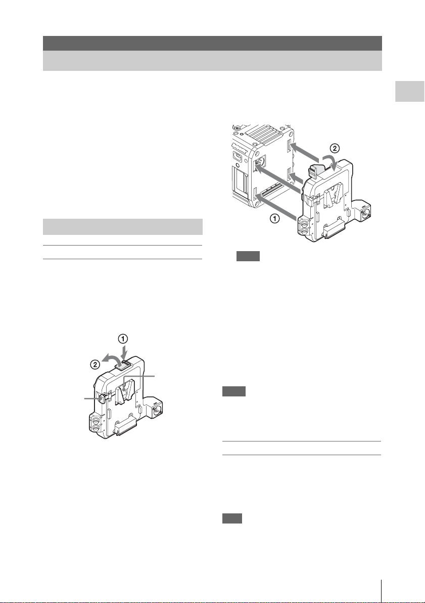
Attaching the AXS-R5
Note
Attach/remove the AXS-R5 while the camcorder is
turned off.
1 Press the release button of the AXS-R5
(1) to pop up the ejection lever, then
raise the ejection lever (2).
• Before lowering the ejection lever, make sure that
the four hooks are attached securely. If the four
hooks are not attached securely, it may cause the
connection to be poor or damage the camcorder
and AXS-R5.
Removing the AXS-R5
Press the release button and raise the
ejection lever, then remove the AXS-R5 by
pulling it out while sliding upward.
Note
Remove the AXS-R5 while supporting the camcorder by
hand.
Inserting an AXS Memory Card
1 Open the cover by sliding the memory
slot cover open/close button on the top
of the AXS-R5.
Preparations
2 Insert the projection of the AXS-R5 into
the slot on the rear of the camcorder
(1), then lower the ejection lever (2).
Notes
• Before attaching the AXS-R5, make sure that the
ejection lever is raised.
2 Insert the AXS memory card into the
card slot with the label facing as
indicated below.
Label
3 Close the cover.
Using an AXS-R5
33
Page 34

Removing an AXS Memory Card
Open the cover of the AXS-R5, press the
EJECT button and remove the AXS
memory card.
Note
Preparations
Data integrity is not guaranteed if the power is turned off
or a memory card is removed while it is being accessed.
Data on the card may be destroyed. Be sure that its
ACCESS lamp is lit in green or off when you turn off the
power or remove a memory card.
Recording to an AXS Memory Card
Set “Shooting Mode” in “Base Setting” (page 90)
to “Cine EI,” and “Main Operation” in “Base
Setting” (page 90) to “RAW” of the System
menu.
For settings of the AXS-R5, see “AXS Recorder”
(page 94) of the System menu.
Formatting an AXS Memory Card
When you use an AXS memory card with the
AXS-R5 that is attached to the camcorder, it must
be formatted using the format function of this
camcorder.
It is also necessary to format an AXS memory
card if a caution message is displayed when the
camcorder is turned on with the AXS recorder
attached.
For an AXS memory card that was formatted with
another system unsupported by the AXS-R5, the
message “Media Needs to be Formatted” is
displayed on the viewfinder screen.
Format the AXS memory card as follows.
Using “Format Media” (page 85) in the
Media menu, specify “AXS Memory” (slot
B), then select “Execute.”
An in-progress message and status bar are
displayed, and the ACCESS lamp lights in red.
When formatting is complete, a completion
message is displayed. Press the MENU dial to
hide the message.
Note
When formatting, all data in an AXS memory card are
erased and cannot be restored.
Checking the Remaining Time Available for Recording
While recording (or standing by to record), you
can check the time remaining for the AXS
memory cards on the AXS memory status/
remaining space indication of the sub display
(page 17) or viewfinder screen (page 20).
The available time for recording with the current
video format (recording bit rate) is calculated
according to the remaining space of each card and
displayed in time units of minutes.
Note
A icon appears if the memory card is writeprotected.
Restoring the AXS Memory Card
If a data error occurs on the AXS memory card for
some reason, the card must be restored.
If an AXS memory card that needs to be restored
is connected, a message prompting you to execute
restoration is displayed on the viewfinder screen.
Restore the card as instructed follows.
Select “Execute” by turning the MENU
dial, then press the MENU dial.
During restoration, the in-progress message and
status bar are displayed, and the ACCESS lamp
lights in red.
When restoration is completed, the completion
message is displayed, then press the MENU dial
to disappear the message.
If restoration fails
• A write-protected AXS memory card or one on
which an error occurred cannot be restored. For
such a card, a warning message is displayed.
Release the write protection or replace the card,
according to the instructions in the message.
• An AXS memory card on which an error
occurred may become usable again through
repeated formatting.
• In some cases, only parts of clips cannot be
restored. Playback of the restored clips becomes
possible again.
Note
For restoration of media recorded with this unit, be sure
to use this unit. Media recorded with a device other than
this unit or with another unit of different version (even of
the same model) may not be restored using this unit.
Using an AXS-R5
34
Page 35

To update the managerial file
If clips cannot be played back, updating the
managerial file on the card may improve the
situation. For this operation, use “Update Media”
(page 85) of the Media menu.
Using a USB Wireless LAN Module
You can make the Wi-Fi connection between the
camcorder and a device such as a smartphone,
tablet, etc., by attaching the supplied IFU-WLM3
USB wireless LAN module.
Note
• The IFU-WLM3 USB Wireless LAN Module
(supplied) may not be available in some countries/
regions.
• Attach/remove the IFU-WLM3 after the camcorder is
turned off.
• If you use a wireless device near the camcorder, the
camcorder may not work correctly. Turn the wireless
device off near the camcorder.
• You cannot use a USB wireless LAN module other
than the IFU-WLM3.
Making a Wi-Fi connection between a device and
the camcorder enables you to do the following.
• Operate the setup menu
• Record and playback the camcorder
• Display the current status of the camcorder
• Switch between the recording settings and
system settings
• Operate the assignable buttons of the camcorder
Preparations
Attaching the IFU-WLM3
1 Open the cover of the USB wireless
LAN module retracting part (page 13).
2 Insert the IFU-WLM3 to the USB
connector.
3 Close the cover.
Using a USB Wireless LAN Module
35
Page 36

Making a Wi-Fi Connection
Complete the connecting process by
inputting the PIN code to the device.
Note
Only one Wi-Fi device can be connected at a time.
To make a network setting
Preparations
Change the “Basic Authentication ” settings (page
94) of the System menu as required.
Item Setting
User Name User name for log-in (factory default
Password Password for log-in (factory default
setting: “admin”)
setting: model name “pmw-f5” or
“pmw-f55”)
For details about the menu settings and entering a
character string, see “Setup Menu Operations”
(page 56).
To make a connection
1 Set “Wi-Fi” in “Wi-Fi” (page 94) of the
System menu to “Enable.”
2 Make a Wi-Fi connection by inputting
the SSID and Password onto the device,
or by using the Wi-Fi direct connection
function.
You can check the SSID and password of the
camcorder on “SSID & Password” in “WiFi” (page 94) of the System menu.
When using the Wi-Fi direct connection
function, proceed to the following step.
3 Select “Execute” for “Wi-Fi Direct
Connection” in “Wi-Fi” of the System
menu.
The setup menu disappears, and the
connection wait message for the Wi-Fi direct
connection function appears.
Using the Push-Button method
When you perform the Push-Button method
on the device, the message for connection
permission appears on the connection wait
screen. Select “Execute.”
Using the PIN code method
When you perform the PIN code method on
the device, the device name and PIN code
appears on the connection wait screen.
Using the Wi-Fi Remote Commander
When a Wi-Fi connection is established between
a device such as smartphone, tablet, etc., and the
camcorder, th e Wi-Fi remote commander appears
on the device screen and the device can be used as
a remote commander.
You can start/stop recording and adjust the
recording settings with a Wi-Fi connected device.
This function is useful for setting the camcorder
in a remote place, such as the top of a crane, etc.
Note
The Wi-Fi remote commander is not capable of the
following functions.
• Zoom, Focus, and Iris control.
• Displaying the thumbnail screen.
Wi-Fi remote commander displays
Smartphone
Main screen
• Wi-Fi connecting
status (Connected/
Disconnected)
• Status indication:
operating status, time
data, audio level meter,
clip name, recording
format, media status/
remaining space,
battery remaining
charge/DC IN voltage
• Recording settings
indication:
S&Q FPS, Shutter,
Color Temp.,
Sensitivity/Gain/
Exposure Index,
Gamma, MLUT, Color
Bars, Auto Black,
Auto White
Using a USB Wireless LAN Module
36
Page 37

Playback screen
Cursor screen
• Wi-Fi connecting
status (Connected/
Disconnected)
• Status indication
• Playback operation
button:
F Rev, Play/Pause,
F Fwd, Prev, Stop,
Next
• Wi-Fi connecting
status (Connected/
Disconnected)
• Status indication
• Cursor operation
button, menu/status
indication:
Up, Left, Set, Right,
Down, Cancel/Back,
Menu, Status
Tablet
Main screen
• Wi-Fi connecting status (Connected/Disconnected)
• Status indication:
operating status, time data, audio level meter, clip
name, recording format, media status/remaining space,
battery remaining charge/DC IN voltage
• Assignable button indication:
Assignable buttons 1 to 4
• Recording settings indication:
S&Q FPS, Shutter, Color Temp., Sensitivity/Gain/
Exposure Index, Gamma, MLUT, Color Bars, Auto
Black, Auto White
Playback screen
Preparations
Assign screen
• Wi-Fi connecting
status (Connected/
Disconnected)
• Status indication
• Assignable button
indication:
Assignable buttons 1
to 4
• Wi-Fi connecting status (Connected/Disconnected)
• Status indication
• Assignable button indication
• Playback operation button:
F Rev, Play/Pause, F Fwd, Prev, Stop, Next
Cursor screen
Using a USB Wireless LAN Module
37
Page 38

• Wi-Fi connecting status (Connected/Disconnected)
• Status indication
• Assignable button indication
• Cursor operation button, menu/status indication:
Up, Left, Set, Right, Down, Cancel/Back, Menu,
Status
Compatible devices
The following devices, using the specified
versions or higher, can be used as Wi-Fi remote
commanders.
To display the Wi-Fi remote commander
Preparations
The display size of the Wi-Fi remote commander
changes according to the device screen size
automatically.
1 Make a Wi-Fi connection between the
device and camcorder (page 36).
2 Launch the browser and input http://
<camcorder’s IP address> (“System
menu” > “Wi-Fi” > “IP Address”)/
rm.html in the address bar.
Example: When the IP address is 10.0.0.1,
input http://10.0.0.1/ in the address bar.
3 Input the user name and password
(“System menu” > “Basic
Authentication” > “User Name” or
“Password”) on the browser.
When completing the connection, the display
of the Wi-Fi remote commander appears on
the device.
Operate the Wi-Fi remote commander by
following the display.
The REC button becomes unavailable when
the Lock switch is dragged to the right.
Notes
• Depending on the device, the Wi-Fi remote
commander may not appear properly on the device’s
screen even though you input http://<camcorder’s IP
address>/rm.html in the address bar. In this case, input
“rms.html” for a smartphone or “rmt.html” for a tablet
instead of “rm.html” at the end of the address to
display the Wi-Fi remote commander properly.
• The Wi-Fi remote commander on the device’s screen
may no longer match the actual status of the camcorder
in the following cases. When this happens, refresh the
browser on the device.
—when the camcorder is restarted while the Wi-Fi
connection is established
—when the camcorder is controlled directly while
the Wi-Fi connection is established
—when the device is reconnected
—when you operate forward/backward on the
device’s browser.
• If the Wi-Fi signal is poor, the Wi-Fi remote
commander may not work properly.
Device OS Browser
Smartphone Android 4.3/4.4 Chrome V31
Tablet Android 4.3/4.4 Chrome V31
iOS 7 Safari 6
iOS 7 Safari 6
Operate the setup menu from the Wi-Fi
remote commander (Tablet only)
To display the setup menu on the tablet, select
“Setup Menu” on the global menu that is
displayed by touching the Menu icon (
upper left of the Wi-Fi remote display of the
tablet.
To return to the camera control screen, select
“Camera Control” on the global menu.
Menu icon
) on the
Using a USB Wireless LAN Module
38
Page 39

You can set/display the following items of the
setup menu on the Wi-Fi remote display (tablet)
(a: compatible, –: not compatible).
Camera menu
White a
Offset White a
Black a
Flare a
Gain a
Shutter a
Slow Shutter a
Auto Exposure –
S&Q Motion a
Color Bars –
Noise Suppression a
Flicker Reduce a
Image Inversion –
Lens Interface –
Paint menu
Gamma a
Black Gamma a
Knee a
White Clip a
Detail a
Aperture a
Skin Detail a
Matrix a
Multi Matrix a
Audio menu
Audio Input –
Audio Level –
Audio Output a
Video menu
Output On/Off a
Output Format a
Output Setting a
Monitor LUT a
Output Display a
VF menu
VF Setting –
Peaking –
Marker a
Zebra –
Display On/Off –
TC menu
Timecode a
TC Display a
Recording menu
Interval Rec a
Picture Cache Rec a
MPEG2 Proxy a
Rec Control a
SDI Rec Control a
Media menu
Update Media –
Format Media a
Clip Naming a
File menu
All File a
Scene File a
User Menu Item –
User Gamma a
Monitor LUT a
Monitor 3D LUT a
Lens File a
Maintenance menu
APR –
Test S aw –
Camera Config –
System menu
System Setting a
Base Setting a
Rec Format a
Genlock –
Assignable Button –
Switch / Lamp –
Fan Control a
Battery Alarm –
DC Voltage Alarm –
Language –
Clock Set –
Hours Meter –
AXS Recorder –
Basic Authentication –
Wi-Fi –
All Reset –
Ve rs i on a
Notes
• When the setup menu is displayed on the Wi-Fi remote
commander, you cannot set the setup menu items other
than “Basic Authentication” and “Wi-Fi” of the
System menu on the camcorder.
• When the setup menu is displayed on the Wi-Fi remote
commander, you cannot change the settings on the sub
display.
Preparations
Using a USB Wireless LAN Module
39
Page 40

Recording
Basic Operation Procedure
Basic recording can be performed with the
following procedures.
1 Make sure that the necessary devices
are attached to the camcorder and
power is supplied to them.
2 Load the memory card(s).
Recording
If you load two cards, recording is continued
by automatically switching to the second
card when the first card becomes full.
3 Set the power switch (page 12) to the ON
position.
The recording screen is displayed on the
viewfinder screen.
4 Press the REC button (page 11).
The REC lamp lights and recording begins.
Note
If the camcorder cannot start recording immediately
after the pressing the REC button, the REC lamp
flashes. The REC lamp lights when recording starts.
5 To stop recording, press the REC
button again.
Recording stops and the camcorder enters
STBY (recording standby) mode.
Playing a recorded clip
You can play the recorded clip while the
camcorder is in standby mode.
1 Insert the SxS memory card.
2 Press the VIEW button in the function
button (page 14) once to display the
VIEW-1 screen.
3 Search the desired clip by pressing Prev
or F Rev button on the sub display.
4 Press the Play/Pause button on the sub
display.
The playback image appears on the
viewfinder.
Playback operation is performed by the buttons
on the sub display.
Play/Pause button: Pauses playback. To resume
playback, press this button again.
F Fwd button/F Rev button: Plays fast. To return
to normal playback, press the Play/Pause
button.
Stop button: Stops playback or recording.
Monitoring audio
In normal playback mode, you can monitor the
recorded audio signals through the built-in
speaker (page 11) or connected headphones.
When connecting the headphones to the
headphones connector (page 14), the built-in
speaker is turned off.
You can select audio channel to be monitored and
adjust the sound volume with “Audio Output”
(page 75) in the Audio menu.
Cueing Up
To start playback from the top of the clip
Press the Prev button or Next button on the sub
display (page 17). You can cue to the top of the
desired clip by pressing the button repeatedly.
Switching the SxS memory cards
When two memory cards are loaded, press the
SLOT SELECT button (page 14) to switch
memory cards.
Note
You cannot switch SxS memory cards during playback.
Continuous playback of cards in slots A and B is not
possible.
Switching to the AXS memory card
You can play the picture that is recorded on the
AXS memory card in the AXS-R5 by developing
simply. To switch to the AXS memo ry card, press
the SELECT button of the AXS-R5. The
playback signal is output from the output
connector of the camcorder.
Basic Operation Procedure
40
Page 41

Note
When connecting the camcorder and AXS-R5, only EE*
is output from the AUX OUT connector of the AXS-R5.
Playback picture is not output. Playback picture is output
from the camcorder.
* EE is not output while in the Slow & Quick Motion
mode.
Clip (recording data)
When you stop recording, video, audio and
subsidiary data from the start to end of the
recording are recorded as a single clip on an
SxS memory card.
Clip name
For each clip recorded with this camcorder, a
clip is named by the naming mode that is set in
“Clip Naming”
(page 85)
of the Media menu.
The Shot Number and clip number are
automatically incremented.
When storing the clip name by the “Cam ID +
Reel#” naming mode (page 8 5), the clip name is
created as follows:
• When there is already a clip name that is
stored by the “Cam ID + Reel#” naming mode
on the inserted AXS memory card, the new
file inherits its information.
Examples:
When “B002C003_XXXXXXXX” is on the AXS
memory card, the next created clip name is
“B002C004_XXXXXXXX.” The Camera ID of
“AXS Recorder” in the System menu is changed to
“B,” and Reel Number is changed to “002.” The clip
name on the information that is displayed during
shooting flashes until the camera starts recording.
• When the inserted AXS memory card has no
file, “1” is added to the Reel Number of the
clip that was recorded last.
Examples:
When you record on empty card “2” after recording
up to “D001CXXX_XXXXXXXX” on card “1,” the
next created clip name is
“D002C001_XXXXXXXX.” The clip name on the
information that is displayed d uring shooting flashes
until the camera starts recording.
• When you set the Camera ID and Reel
Number of “Clip Naming” in the Media
menu, that information is applied.
Examples:
When you change the Camera ID to “F” and Reel
Number to “001” of the AXS memory card that is
recorded up to “E003CXXX_XXXXXXXX,” the
next clip name is “F001CXXX_XXXXXXXX.”
When you change the Camera ID only, the Reel
Number is changed to “001.”
When storing the clip name by the “Title”
naming mode (page 85), the clip name is
created from characters that are set in “Title
Prefix” (1 to 46 characters) + clip number that
is set in “Number Set” (0001 to 9999).
Maximum duration of a clip
The maximum clip length is 6 hours.
If you exceed the maximum clip length, a new
clip will be automatically created. You can
check the new clip on the thumbnail screen.
Recording
Basic Operation Procedure
41
Page 42

Changing Basic Settings
You can make changes to the settings based on
the intended usage of the recorded video or
recording conditions.
Electronic Shutter
Set the shutter speed (cache time).
When you set “Setting” in “Shutter” (page 64) of
Recording
the Camera menu to “On,” the shutter speed that
you specified with “Shutter” is turned on.
Note
When the viewfinder double speed drive function (page
46) is activated, the electronic shutter function is locked
to on, and the shutter angle is limited up to 180 degrees.
Setting the shutter mode and speed
Select “Mode” and “Select” in “Shutter” (page
64) of the Camera menu, then set the speed in
“Shutter Value.”
Shooting in slow shutter
The shutter speed is specified in the number of
accumulated frames. This function allows you to
obtain low-noise clear pictures in low light levels
or surreal pictures with afterimages.
Set “Setting” in “Slow Shutter” (page 65) of the
Camera menu to “On,” and specify the number of
accumulated frames with “Number of Frames.”
Sensitivity/Gain/Color Temperature/White Balance
The setting items differ, depending on the
shooting mode setting.
These items can be set on the setup menu and sub
display.
off, is recorded as the main recorded signal.
Sensitivity for the main recorded signal is locked
to standard sensitivity, and the picture brightness
is changed in accordance with the EI value only
for the output picture, for which MLUT is set to
on.
You can check the processing result of sensitizing
or desensitizing on post-production while
shooting by using the picture, for which MLUT is
set on.
You can set the following values for the
sensitivity (EI value)
PMW-F5: 500EI, 640EI, 800EI, 1000EI, 1250EI,
1600EI, 2000EI, 2500EI, 3200EI, 4000EI,
5000EI, 6400EI, 8000EI
PMW-F55: 320EI, 400EI, 500EI, 640EI, 800EI,
1000EI, 1250EI, 1600EI, 2000EI, 2500EI,
3200EI, 4000EI, 5000EI
Select the color temperature from among “Preset
3200K” (tungsten), “4300K” (tungsten), and
“5500K” (daylight), in “White” (page 59) of the
Camera menu.
While in “Custom” mode: Selecting the
sensitivity or gain, and color
temperature or white balance
Select the sensitivity (ISO) or gain (dB) in “Gain”
(page 61) of the Camera menu.
Select the color temperature or white balance in
“White” of the Camera menu.
The color temperature can be selected for
Memory A/Memory B from among “Preset
3200K” (tungsten), “4300K” (tungsten), and
“5500K” (daylight), and you can select any color
temperature by using “Color Temp.” in “White”
(page 59) of the Camera menu.
For white balance, adjust automatically by using
“Auto White Balance,” or adjust Memory A/
Memory B by using “Color Temp. Balance,” “R
Gain,” or “B Gain,” in “White” of the Camera
menu.
While in “Cine EI” mode: Selecting the
sensitivity (EI value) and color
temperature
Set the sensitivity by using “Exposure Index” in
“Gain” (page 61) of the Camera menu.
For the Cine EI mode, it is assumed that the RAW
signal or output picture, for which MLUT is set to
Changing Basic Settings
42
Page 43

Audio
To adjust the audio levels
When “CH-1 Audio Select/CH-2 Audio Select”
in “Audio Level” (page 75) of the Audio menu is
set to “Auto,” the audio recording levels are
automatically adjusted.
To adjust the audio recording levels manually, set
to “Manual.” Adjust the audio recording levels on
“CH-1 Audio Level/CH-2 Audio Level” in
“Audio Level” of the Audio menu.
Note
The recording level is locked for channels with AES/
EBU signals selected for audio input.
Time Data
Setting the Timecode
Specify the timecode to be recorded with
“Timecode” in the TC/UB menu (page 83).
Useful Functions
Assignable Buttons
The camcorder ha s four assignable buttons (pages
11, 13) to which you can assign various functions
for convenience.
You can also assign the function to the RET
button on the lens.
Changing functions
Use “Assignable Button” (page 92) in the System
menu.
The assigned functions can be viewed on the
Assignable button status screen (page 12).
Assigned functions
Function name Function
Marker Turning on/off the Center Marker,
Zebra Turning on/off the Zebra function.
Peaking Turning on/off the Peaking
Display Turning on/off the monitor display
Video Signal
Monitor
VF Focus
Magnifier
VF Mode Switching viewfinder screen
Rec Starting/stopping recording.
S&Q Motion Turning on/off the Slow & Quick
Picture Cache Rec Turning on/off the Picture Cache
Rec Review Performing the Rec Review
High/Low Key Switching between High Key
White Memory Switching “White Switch”
Safety Zone, Aspect Marker.
function.
of status/setting value.
Switching the waveform
indication for the output signal
from SDI (Sub).
Turning on/off the Focus
Magnifier function of the
viewfinder.
between color and mono.
Motion.
Rec function.
function.
(monitoring display for high key
blown-out highlights), Low Key
(monitoring display for low key
clipped blacks), and Off (normal
display).
between Memory A and Memory
B.
Recording
Useful Functions
43
Page 44

Function name Function
VF High Contrast Enhancing the contrast of the
Color Bars Turning the color bar on/off.
pictures on the viewfinder.
Slow & Quick Motion
When “Main Operation” is set to “RAW” or
“YPbPr,” and the system frequency and video
format (page 90) are set as follows, you can set
the recording frame rate and playback frame rate
to different values.
Recording
Main
Operation
RAW – (When
YPbPr XAVC
* Setting value is 1 to 60 when “High Frame Rate
Mode” is set to “Off.”
** When recording on AXS and SxS simultaneously, the
setting value is for SxS.
Notes
• Slow & Quick Motion mode cannot be used while
recording, playing, or displaying thumbnail.
• Slow & Quick Motion mode cannot be used while the
Slow Shutter mode.
• Audio cannot be recorded while in the Slow & Quick
Motion mode.
• When “High Frame Rate Mode” is set to “Full Scan”
and the frame rate is set to more than 61P, moiré may
occur in high resolution areas of the picture. In this
case, you can reduce moiré by attaching an optional
CBK-55F2K Optical 2K Filter.
• When “High Frame Rate Mode” is set to other than
“Off,” the camcorder cannot switch to the second card
automatically even if a card becomes full.
• Slow & Quick Motion function is not possible in
Interval Rec and Picture Cache mode. The camcorder
exits Interval Rec and Picture Cache mode whenever
you select Slow & Quick Motion mode. The
camcorder exits Slow & Quick Motion mode
Recording
format
recording on
an AXS only)
4096 × 2160P
XAVC
3840 × 2160P
XAVC
2048 × 1080P
XAVC
1920 × 1080P
System
frequency
23.98P/24P/
25P/29.97P/
50P/59.94P
23.98P/24P/
25P/29.97P/
50P/59.94P
23.98P/25P/
29.97P/50P/
59.94P
23.98P/24P/
29.97P/
59.94P
25P/50P 1 to 150P*
23.98P/
29.97P/
59.94P
25P/50P 1 to 150P*
Frame
*
rate
1 to
**
240P
1 to 60P
1 to 60P
1 to 180P*
1 to 180P*
automatically whenever you select Interval Rec or
Picture Cache mode.
Recording Time-lapse Video (Interval Rec Function)
The camcorder’s Interval Rec function allows
you to capture time-lapse videos to the
camcorder’s internal memory. This function is an
effective way to shoot slow-moving subjects.
When “Setting ” in “Interval Rec” (pag e 84) of the
Recording menu is set to “On,” and you start
recording, the camcorder automatically records a
specified number of frames at a specified interval
time.
Interval time
Number of frames in one take
The Interval Rec function is available when
“Main Operation,” “Rec Control,” and the
recording format are set to the following settings.
Main
Operation
RAW AXS –
RGB – XAVC 2048 × 1080P
YPbPr – XAVC 4096 × 2160P
Notes
• The Interval Rec function cannot be used at the same
time as the Slow & Quick Motion or Picture Cache
function. When you select Interval Rec mode, the Slow
& Quick Motion and Picture Cache functions are
disabled. When you select Slow & Quick Motion or
Picture Cache mode, the Interval Rec function is
disabled.
Rec
Recording format
Control
SxS & AXS XAVC 2048 × 1080P
XAVC 1920 × 1080P
XAVC 1920 × 1080P
XAVC 3840 × 2160P
XAVC 2048 × 1080P
XAVC 1920 × 1080P
Useful Functions
44
Page 45

• The simultaneously recording function is not av ailable
in Internal Rec mode.
• Interval Rec settings cannot be changed during
recording.
• The following are limitations for the Interval Rec
function.
—Audio signals will not be recorded.
—You cannot perform the Rec Review function.
—The signal will not be genlocked.
after the change. The camcorder exits Picture Cache
mode automatically.
• The simultaneously recording function is not available
in Picture Cache mode.
• It is not possible to change the picture cache setting
during recording.
• It is not possible to change the setting of the viewfinder
double speed drive function during recording.
Starting to Record from Prestored Video (Picture Cache
Function)
You can begin recording a specified number of
seconds in advance by storing up to 15 seconds of
video and audio data in the internal memory of
the camcorder when you start recording.
When you start recording after setting “Setting”
in “Picture Cache Rec” (page 84) of the
Recording menu to “On,” the camcorder records
in advance of the specified time (Cache Rec
Time).
The Picture Cache function is available for either
of the following settings.
• The system frequency is set to 29.97/25/24/
23.98, and the recording format is set to XAVC
4096 × 2160P/XAVC 3840 × 2160P/XAVC
2048 × 1080P/XAVC 1920 × 1080P.
• The recording format is set to MPEG 1920 ×
1080P/MPEG 1920 × 1080i/MPEG 1280 ×
720P.
The selected Picture Cache mode is retained until
the setting is changed.
Notes
• If the system frequency is set to 29.97, 25, 24, or 23.98,
the “Cache Rec Time” setting is limited depending on
the recording format.
—For XAVC 4096 × 2160P, XAVC 3840 × 2160P:
Locked to “0-2sec.”
—For XAVC 2048 × 1080P, XAVC 1920 × 1080P:
“8-10sec” and “13-15sec” cannot be selected.
• Picture cache recording is not possible in Slow &
Quick Motion and Interval Rec mode. The camcorder
exits Slow & Quick Motion and Interval Rec mode
whenever you select Picture Cache mode. The
camcorder exits Picture Cache mode automatically
whenever you select Slow & Quick Motion or Interval
Rec mode.
• The data stored in picture cache memory is cleared
when you change system settings, such as the
recording format. Picture data from before the change
is not recorded even if you start recording immediately
Simultaneously Recording
You can record the two sizes of pictures
simultaneously on an SxS memory card in one
slot. You can also record HD signal on the SxS
memory card in the camcorder while recording
picture and audio of RAW format on the AXSR5.
Note
While simultaneously recording, the camcorder cannot
switch to the second card automatically even if a card
becomes full.
Recording simultaneously on one
memory card – MPEG2 Proxy function
For the PMW-F55, set “Setting” in “MPEG2
Proxy” (page 84) of the Recording menu to “On”
while the recording format is set to XAVC 4096
× 2160/XAVC 3840 × 2160 29.97P/25P/23.98P,
or SStP SR-SQ 444/SStP SR-SQ 422 59.94i/
29.97P.
For the PMW-F5, by installing the optional
CBKZ-55FX, the MPEG2 Proxy function is
available while the recording format is set to
XAVC 4096 × 2160/XAVC 3840 × 2160 29.97P/
25P/23.98P.
The picture of XAVC 4096 × 2160/XAVC 3840
× 2160 or SStP SR-SQ 444/SStP SR-SQ 422, and
the picture signal of MPEG2 1920 × 1080 are
recorded simultaneously on one SxS memory
card.
The clip of XAVC 4096 × 2160/XAVC 3840 ×
2160 or SStP SR-SQ 444/SStP SR-SQ 422 is
recorded under the XDROOT/Clip directory on
the SxS memory card, but the clip of MPEG2
1920 × 1080 is recorded under the XDROOT/Sub
directory on the SxS memory card, and the suffix
“S02” is added to the end of the clip name.
Notes
• This function cannot be used while in the Slow &
Quick Motion, Interval Rec, or Picture Cache Rec
mode.
Recording
Useful Functions
45
Page 46

• The MLUT setting is locked to “MLUT On” for the
MPEG2 Proxy video that is recorded simultaneously
when in the Cine EI mode.
Recording on the AXS and SxS memory
simultaneously
Set “Setting” in “Rec Control” (page 84) of the
Recording menu to “SxS & AXS,” while “Main
Operation” in “Base Setting” (page 90) of the
System menu is set to “RAW.”
You can simultaneously record pictures of RAW
format and pictures with formats set by “Rec
Format.”
Recording
False Color Display
You can perform the false color display on the
viewfinder by pressing the SPARE button of the
viewfinder (DVF-EL100, DVF-L700) that is
attached to the camcorder.
For details about the false color display, refer to the
operating instructions of the DVF-EL100 or DVFL700.
Note
The false color display is available only when the
“Gamma” setting for the video signal that is output to the
viewfinder is set to “S-Log2.”
Rec Review
You can review the last recorded clip on the
screen (Rec Review) by assigning the Rec
Review function to an assignable button (page
43).
When you stop recording and press the assigned
button, the last 2 seconds of the clip are played.
When you press and hold the button for more than
1 second, the camcorder starts to rewind from two
seconds before of the last frame of the clip at 4×
speed. When you release the button, the
camcorder starts playback at that point.
Rec Review stops at the end of the clip, then
resumes STBY (recording standby) status.
Note
The Setup menus cannot be operated during Rec Review.
Focus Magnifier
By pressing the FOCUS MAG button of the
viewfinder (DVF-L350, DVF-EL100, DVFL700) that is attached to the camcorder, you can
expand the center part of the viewfinder, and it is
easy to adjust the focus. After adjusting the focus,
press the button again to returns to the normal
(recording) screen.
It does not affect the recorded image or output
signal in the focus magnifier mode.
Viewfinder Double Speed Drive Function
If the system frequency is 23.98P, 24P, 25P, or
29.97P, the image may be blurred and hard to see
because of low frame frequency when you shoot
while swaying the camcorder to the right and the
left.
In this case, you can decrease image blur and
make it easier to see by activating the viewfinder
double speed drive function.
To activate, set “Double Speed Drive” in “VF
Setting” (page 80) of the VF menu to “On.”
Notes
• This function is not effective on the following settings.
—System frequency is 59.94/50.
—Recording format is SStP SR-SQ 444/SStP SR-
Lite 422/SStP SR-SQ 422.
—“Setting” in “Slow Shutter” of the Camera menu is
set to “On.”
—“Setting” in “S&Q Motion” of the Camera menu is
set to “On,” and the “Frame Rate” setting is 1 to
60P.
• When this function is effective and “Setting” in “S&Q
Motion” of the Camera menu is set to “Off,” the
electronic shutter function is locked to on, and the
shutter angle is limited to 180 degrees.
Useful Functions
46
Page 47

Thumbnail Screens
Thumbnail Screens
When you press the Thumbnail button of the sub display (page 17), clips recorded on the SxS memory
card are displayed as thumbnails on the screen.
You can start playback from the clip selected on the thumbnail screen. The playback picture can be seen
on the viewfinder screen and external monitors.
Press the Thumbnail button of the sub display to exit the thumbnail screen and return to the recording
screen.
Configuration of the Screen
Information for the clip selected with the cursor are displayed at the bottom of the screen.
The icon of the current SxS memory card is highlighted, shading the nonselected
one. (If the card is write-protected, a lock icon is displayed to the left.)
Current clip No./ Total number of clips
Cursor
(yellow)
Thumbnail Screens
1. Thumbnail
The thumbnail image for each clip is an index
frame from the clip. When recording, the first
frame of a clip is automatically set as the index
frame.
Below each thumbnail, the clip/frame
information is displayed. You can change the
displayed item on “Thumbnail Caption” in
“Customize View” (page 48) of the thumbnail
menu.
2. Clip name/title
The clip name or title of the selected clip is
displayed.
3. File format
The file format of the selected clip is displayed.
4. Recording video format
5. Special recording information
If the selected clip was recorded in a special
recording mode, the mode is displayed.
Clips recorded in Slow & Quick Motion display
the frame rate to the right.
6. Duration of the clip
7. Creation date and time
Thumbnail Screens
47
Page 48

Playing Clips
Playing the Selected and Subsequent Clips in Sequence
1 Turn the MENU dial (page 11) to move
the cursor to the thumbnail image of the
clip with which you wish to start
playback.
Clip Operations
On the thumbnail screen, you can operate the
clips or confirm the subsidiary data for clips using
the thumbnail menu. The thumbnail menu
appears when you press the OPTION button
(page 13) on the thumbnail menu.
Operations of the Thumbnail Menu
2 Press the MENU dial.
Playback starts from the beginning of the
selected clip.
Notes
Thumbnail Screens
• To start playback by pressing the MENU dial, set “Set
Key on Thumbnail” in “Switch/Lamp” (page 93) of
the System menu to “Play.”
• The playback picture may be momentarily distorted or
frozen between clips. You cannot operate the
camcorder during this condition.
• When you select a clip on the thumbnail screen and
start playback, the playback picture at the beginning of
the clip may be distorted. To start playback without
distortion, pause playback once after starting it, press
the Prev button on the sub display (VIEW-1) to return
to the top of the clip, then restart playback.
Turn the MENU dial (page 11) to select a menu
item, then press the MENU dial.
Pressing the CANCEL/BACK button (page 11)
restores to the previous condition.
Pressing the OPTION button while the thumbnail
menu is displayed turns the thumbnail menu off.
Notes
• When the SxS memory card is write-protected, some
operations are unavailable.
• There may be items that cannot be selected, d epending
on the status when the menu is displayed.
Clip operation menu
Display Clip Properties
Displays the detailed information of a clip screen
(page 49).
Copy MPEG2 Proxy (PMW-F55 and PMW-F5 +
CBKZ-55FX)
Copy All Clips: Copies a ll the MPEG2 Proxy data
to the destination media as a clip (page 49).
Delete Clip
Select Clip: Deletes the selected clip (page 50).
Customize View
Thumbnail Caption: Changes the items that are
displayed under the thumbnail screen. (page
50)
Playing Clips / Clip Operations
48
Page 49

Displaying the Detailed Information of a Clip
Select “Display Clip Properties” from the thumbnail menu.
1. Image of the current clip
2. Timecode
TC Index: Timecode of the displayed frame
Start: Timecode at the recording starting point
End: Timecode at the recording ending point
Duration: Duration of the clip
3. Date of recording/modifying
4. Clip name
5. Clip title 1/2
6. Recording format
Video Codec: Video codec
Size: Picture size
FPS: Frame rate
Audio Codec: Audio codec
Ch/Bit: Number of the recorded audio channel/
audio recording bit
7. Special recording information
8. Recording device name
Copying MPEG2 Proxy Data
(PMW-F55 and PMW-F5 + CBKZ55FX)
You can copy a ll the MPEG2 Proxy data re corded
on the clip to another SxS memory card as a clip.
Each clip is copied to the destination SxS memory
card and given the same name as the MPEG2
Proxy data with its suffix “S02” deleted.
Notes
• If there is another clip having the same name on the
destination SxS memory card, the clip is copied under
a name adding a single-digit number in parentheses to
the end of the original clip name.
The parenthetical number is the minimum value that
does not exist in the destination memory card.
Examples:
ABCD0002(1) if ABCD0002 exists
ABCD0002(2) if ABCD0002(1) exists
ABCD0005(4) if ABCD0005(3) exists
• You cannot copy a file 1000 times or more if clips with
the same clip name followed by parenthetical numbers
(1) to (999) already exist on the card.
• A warning message is displayed if there is not
sufficient space on the destination SxS memory card.
Replace the SxS memory card with one with sufficient
space.
Thumbnail Screens
Clip Operations
49
Page 50

Deleting Clips
You can delete clips from the SxS memory card.
Select “Select Clip” from “Delete Clip” on the
thumbnail menu.
You can select multiple clips to be deleted. Press
the OPTION button (page 13) after selecting the
clip to be deleted.
Changing Information on the Thumbnail Screen
You can change information of the clip/frame t hat
is displayed under thumbnail.
Select the displayed item from “Thumbnail
Caption” in “Customize View” on the thumbnail
menu.
Thumbnail Screens
Date Time: Creation date or modified time
Time Code: Timecode
Duration: Duration
Sequential Number: Thumbnail number
50
Clip Operations
Page 51

Settings
Sub Display Operation
You can check the status of the camcorder, set
basic settings for the camcorder, and operate
playback on the sub display.
• CAMERA screen: Basic settings of the
camcorder
• FILE screen: Loading the file
• AU/TC screen: Settings for audio or timecode
• VIEW screen: Playback and operation on the
thumbnail screen
For details about the screen of the sub display, see
“Sub Display Screen” (page 17) in “On-Screen
Indications.”
Controls
Function buttons (page 14)
Switches the screen of the sub display.
If there are multiple screens for a function, press
the function button repeatedly.
• CAMERA button
• FILE button
• AU/TC (audio/timecode) button
• VIEW button
Item button (page 14)
Selects the item of the sub display.
SEL/SET dial (MENU dial) (page 11)
When you turn it, the cursor moves in the
corresponding direction, permitting you to select
menu items or setting values.
Press the MENU dial to select the item.
CANCEL/BACK button (page 11)
To return to the previous layer of the menu. An
uncompleted change is canceled.
Note
When the setup menu is being displayed by
pressing the MENU button (page 13), or the
status display is being displayed by pressing the
STATUS button (page 12), you cannot operate
other than the VIEW screen.
Setting the basic items
1 Press the function button to select the
screen of the function to be set.
2 Press the item button to select the item
to be set.
Setting value of the item that can be set is
orange.
3 Turn the MENU dial to move the cursor
to the item to be set.
Settings
4 Press the MENU dial to enter the
selected item.
Using the sub display as the operation
button
Press the VIEW button (page 14) to display the
VIEW-1/VIEW-2 screen (page 18), then operate
the displayed function with the item button. The
cursor operation on the sub display is used on the
setup menu (page 56) and the clip operation (page
48).
Sub Display Operation
51
Page 52

Sub Display Setting Items
The item names and its settings are listed below.
Note
When the CBK-55BK (EFP Style Buildup Kit) is attached to the camcorder, some operations and settings are limited.
CAMERA Screen
CAMERA-1
Item name Setting
S&Q FPS
Shutter
Settings
Color Temp
On: Turns the Slow & Quick motion mode on, and sets the frame rate. (See page 66 for
the selectable item.)
Off: Turns the Slow & Quick motion mode off.
Sets the electronic shutter speed and shutter angle.
Select from following 11 types of items.
Off: Turns the electronic shutter function off.
Value of Step Shutter: Selects from 8 types of presets that are registered as Step Shutter.
(You can change the preset value after selecting.)
Continuous: Selects the available speed/angle. (See page 64 for the selectable item.)
SLS: Selects the slow shutter function. (Set the number of frames to accumulate after
selecting.)
When the CBK-55BK is attached
The SHUTTER switch on the CBK-55BK takes priority.
If the SHUTTER switch is set to OFF, “Value of Step Shutter” and “Continuous” cannot
be selected.
If the SHUTTER switch is set to ON, “Off” cannot be selected.
Sets the color temperature of the white balance.
Preset 3200K/4300K/5500K: Sets the white balance to the preset value of color
temperature 3200K/4300K/5500K.
Memory A/Memory B: Sets the color temperature of the white balance that is stored on
the white memory A or B.
Note
“Memory A”/”Memory B” cannot be selected when “Shooting Mode” (page 90) is set to
“Cine EI.”
When the CBK-55BK is attached
The WHITE BAL switch on the CBK-55BK takes priority.
When “Shooting Mode” (page 90) is set to “Custom,” “Preset 3200K/4300K/5500K,”
and “Memory A/Memory B” cannot be changed on the sub display.
If the WHITE BAL switch is set to PRST, “Memory A/Memory B” cannot be selected.
If the WHITE BAL switch is set to A or B, only the color temperature of the white
balance that is stored on the white memory on each Memory A/Memory B can be set.
If “Shooting Mode” is set to “Cine EI,” the preset value can be selected from Preset
3200K/4300K/5500K for each position of the WHITE BAL switch.
Sub Display Setting Items
52
Page 53

Item name Setting
Sensitivity/Gain/
Exposure Index
Sets the sensitivity/gain.
The item name (Sensitivity/Gain) and setting value differ, depending on the “Mode”
setting in “Gain” (page 61). (See page 61 for the selectable item.)
The item name becomes “Exposure Index” and sets the EI value when “Shooting Mode”
(page 90) is set to “Cine EI.” (See page 62 for the selectable item.)
User Gamma: Selects the user gamma. (User1 / User2 / User3 / User4 / User5)
When the CBK-55BK is attached
You can select the setting value for each position (L/M/H) of the GAIN/EI switch on the
CBK-55BK. The GAIN switch position is displayed on the left of the setting value.
Gamma/High Latitude
Sets the gamma category and gamma table.
STD: Selects the standard gamma. STD1 DVW / STD2 ×4.5 / STD3 ×3.5 / STD4 240M
/ STD5 R709 / STD6 ×5.0
HG: Selects the hyper gamma. HG1 3250G36 / HG2 4600G30 / HG3 3259G40 / HG4
4609G33 / HG7 8009G40 / HG8 8009G33
S-Log2: Selects S-Log2.
S-Log3: Selects S-Log3.
Note
“High Latitude” is displayed when “Shooting Mode” (page 90) is set to “Cine EI.”
MLUT
Selects and sets LUT/Look Profile. (See page 78 for the selectable item.)
CAMERA-2
Item name Setting
Color Bars
Auto White
Auto Black
Sub&HDMI
Viewfinder
SDI (Sub) Disp.
Turns the color bars on/off.
Performs the auto white balance function.
(This setting is available only when “White Switch” is set to “Memory A/Memory B.”)
Performs the auto black balance function.
Selects whether to apply monitor LUT for the output image from SDI (Sub) and HDMI
when “Shooting Mode” (page 90) is set to “Cine EI.”
Selects whether to apply monitor LUT for the viewfinder image when “Shooting Mode”
(page 90) is set to “Cine EI.”
Select whether to output the character information and marker to the SDI (Sub) output.
FILE Screen
FILE-1
Item name Setting
All File Load 1 to 6
FILE-2
Item name Setting
Scene Recall 1 to 5/
Standard
Loads the All file (1 to 6) from the SD card that is inserted into the SD card slot.
Loads the Scene file (1 to 5, or Standard) from the internal memory.
Settings
Sub Display Setting Items
53
Page 54

FILE-3
Item name Setting
Lens Recall 1 to 6
Loads the Lens file (1 to 6) from the internal memory.
AU/TC (audio/timecode) Screen
AU/TC-1
Item name Setting
MIC CH1 Ref
CH1 Input
Settings
CH1 Select
MIC CH2 Ref
CH2 Input
CH2 Select
Select the reference input level when the AUDIO IN CH1 switch is set to MIC from –60
dB/–50 dB/–40 dB.
When the CBK-55BK is attached
The item name is changed to “Rear MIC1 Ref,” and sets the reference level when the
AUDIO IN CH-1 switch on the rear of the CBK-55BK is set to MIC (select from –70
dB/–60 dB/–50 dB/–40 dB/–30 dB).
Auto: Adjusts the recording level automatically.
Manual: Adjust the recording level manually from –99 to +99.
Note
If the AES/EBU signal is selected for the audio input signal, the recording level is locked.
When the CBK-55BK is attached
This item does not appear because the setting of this item follows the settings of the
AUDIO SELECT CH-1 switch and position of the LEVEL CH-1 knob on the CBK55BK.
Displays the input source for AUDIO IN CH1.
When the CBK-55BK is attached
The input source of AUDIO IN CH-1 on the rear of the CBK-55BK is displayed.
Select the reference input level when the AUDIO IN CH2 switch is set to MIC from –60
dB/–50 dB/–40 dB.
When the CBK-55BK is attached
The item name is changed to “Rear MIC2 Ref,” and sets the reference level when the
AUDIO IN CH-2 switch on the rear of the CBK-55BK is set to MIC (select from –70
dB/–60 dB/–50 dB/–40 dB/–30 dB).
Auto: Adjusts the recording level automatically.
Manual: Adjust the recording level manually from –99 to +99.
Note
If the AES/EBU signal is selected for the audio input signal, the recording level is locked.
When the CBK-55BK is attached
This item does not appear because the setting of this item follows the settings of the
AUDIO SELECT CH-2 switch and position of the LEVEL CH-2 knob on the CBK55BK.
Displays the input source for AUDIO IN CH2.
When the CBK-55BK is attached
The input source of AUDIO IN CH-2 on the rear of the CBK-55BK is displayed.
Sub Display Setting Items
54
Page 55

AU/TC-2
Item name Setting
Monitor CH
Selects the audio channel that is output to the headphones and speaker. (See page 75 for
the selectable item.)
When the CBK-55BK is attached
The status of the MONITOR switch on the CBK-55BK is displayed.
Monitor Level
Adjusts the monitor volume from 0 to 99.
When the CBK-55BK is attached
This item does not appear because the setting of the item is adjusted on the MONITOR
knob on the CBK-55BK.
AU/TC-3
Item name Setting
Display
Reset
Set
Mode
Run
TC Source
Switches the indication for the time data (Timecode/Duration).
Resets the timecode and counter to 00:00:00:00.
Sets the timecode to the desired value.
Sets the timecode mode.
Preset (Ext): Starts the timecode from the specified value.
Int. Regen (regeneration): Starts the timecode from that of the previous clip.
Sets the condition for the timecode.
Rec Run: Advances the timecode during recording only.
Free Run: Keeps advancing regardless of the state of recording.
Displays the external lock status for the timecode.
Internal: The timecode is not locked when “S&Q Motion” is set to “Off” and timecode is
set to “Preset (Ext-Lk)” and “Free Run.”
External: The timecode is locked when “S&Q Motion” is set to “Off” and timecode is set
to “Preset (Ext-Lk)” and “Free Run.”
No indication: Other than above.
Settings
Sub Display Setting Items
55
Page 56

Setup Menu Operations
The Setup menu allowing you to perform various
settings that are needed for recording and playing,
appears on the viewfinder screen by pressing the
MENU button. (You can display the Setup menu
on the external video monitor or sub display.)
Menu controls
MENU button (page 13)
To turn the menu mode to use the setup menus on/
off.
SEL/SET dial (MENU dial) (page 11)
When you turn the dial, the cursor moves up or
down, permitting you to select menu items or
setting values.
Press the MENU dial to select the highlighted
item.
CANCEL/BACK button (page 11)
To return to the previous menu. An uncompleted
Settings
change is canceled.
Up/Down/Left/Right buttons, SET button (page
18)
When you press the up/down/left/right buttons on
the sub display (VIEW-2), the cursor moves in
the corresponding direction, permitting you to
select menu items or setting values.
Press the SET button to enter the highlighted
item.
Note
In the focus magnifier mode (page 46), the setup menu
cannot be used.
Setting the Setup menus
Turn the MENU dial to set the cursor to the item
of the menu you wish to set, then press the MENU
dial to select that item.
• The menu item selection area can show 9 lines
at maximum. When all the selectable items
cannot be displayed at one time, you can scroll
the display up or down by moving the cursor.
• For items having a wide range of available
values (example: –99 to +99), the available
value area is not displayed. The current setting
is highlighted instead, indicating that the setting
is ready for change.
• When you select “Execute” for an execution
item, the corresponding function is executed.
• When you select an item that you must confirm
before execution, the menu display temporarily
disappears, and a confirmation message is
displayed. Follow the instructions of the
message, and specify whether to execute or
cancel.
Entering a character string
When you select an item for which a character
string, such as a filename, is to be specified, the
character input screen appears.
1
23
1 Select character type by turning the
MENU dial, then press the MENU dial
to enter.
ABC: Uppercase alphabetical
abc: Lowercase alphabetical
123: Numerical
!#$: Special
2 Select a character from the selected
character type.
The cursor moves to the next column.
Space: Inputs space on the position of the
cursor.
T/t: Moves the cursor.
BS: Deletes a character on the left of the
cursor.
3 Select “Done” after inputting
characters.
The input characters are entered and the
character input screen disappears.
Setup Menu Operations
56
Page 57

User Menu
The User Menu consists of the items that are
copied from the Camera, Paint, Audio, Video,
VF, TC/UB, Recording, Media, File,
Maintenance, and System menu. By registering
the highly-used items in advance, you can easily
recall the desired item.
You can register up to 20 items for the User
Menu.
The User Menu consists of the following hierarchies.
The following 10 items are registered for the
default setting.
• System Setting (System menu)
• Base Setting (System menu)
• Rec Format (System menu)
• Rec Control (Recording menu)
• Output Format (Video menu)
• Monitor LUT (Video menu)
• Clip Naming (Media menu)
• VF Setting (VF menu)
• Assignable Button (System menu)
• Format Media (Media menu)
First hierarchy Second hierarchy Third hierarchy List of edit
functions
User Menu Registered item Sets the item.
Edit User Menu Registered item Delete Deletes the item.
Move Moves the item.
Edit Subitem Edits the subitem.
Add Item Adds the item.
Customize Reset Returns the registration
The customized User Menu items can be stored
on an SD Card as the User Menu Item file. You
can load the User Menu items from the SD Card.
Note
You cannot register double items/subitems and change
the name of items/subitems.
Editing the registered item
1 Display the User Menu of the setup
menu.
The registered items are displayed.
2 Select “Edit User Menu” from the User
Menu.
3 Select the item for editing.
The list for edit functions is displayed.
4 Select the edit item.
Delete: Deletes the selected item.
Move: Moves the selected item. Move the B
mark to the desired position.
Edit Subitem: Edits the subitem of the
selected item. Select the subitem and decide
registering/unregistering of the subitem by
performing the decision operation (selection/
deselection of the checkbox). Select “OK”
after setting.
Adding items
1 Select the User Menu > “Edit User
Menu” > “Add Item.”
Items that can be registered to the User Menu
are displayed.
2 Select the item that you want to register.
The subitem editing display of the selected
item is displayed.
3 Select registering/unregistering of the
subitem.
Select the subitem and decide registering/
unregistering of the subitem by performing
the decision operation (selection/deselection
of the checkbox).
4 Select “OK.”
The added item is displayed on the User
Menu.
Contents
to the default.
Settings
Setup Menu Operations
57
Page 58

Return the User Menu registration to the
default setting
1 Select the User Menu > “Edit User
Menu” > “Customize Reset.”
2 Select “Reset” > “Execute.”
Settings
Setup Menu Operations
58
Page 59

Setup Menu List
The functions and available settings of menus are listed below.
The default settings set at the factory are shown in bold face (example:
Preset 3200K).
Note
If the CBK-55BK (EFP Style Buildup Kit) is attached to the camcorder, some items are added, and some operations and
settings are limited.
Camera Menu
Camera
Menu items Sub items and setting values Contents
White
Setting for white
balance
Auto White Balance
Execute / Cancel
White Switch
Preset 3200K / Preset 4300K /
Preset 5500K / Memory A /
Memory B
Color Temp.
1500K to 50000K (3200K)
Color Temp. Balance
–99 to +99 (±0)
Performs the auto white balance function.
Execute: Executes this function.
(This setting is available only when “White Switch” is set to
“Memory A/Memory B.”)
Sets the operation mode for “White.”
Preset 3200K/4300K/5500K: Set the white balance to the
preset value of the color temperature 3200K/4300K/5500K.
Memory A/Memory B: Adjusts the white balance manually.
Perform the auto white balance function (one push).
(“Memory A/Memory B” is available only when “Shooting
Mode” in “Base Setting” of the System menu is set to
“Custom.”)
When the CBK-55BK is attached
When “Shooting Mode” (page 90) is set to “Custom,” this
item is available only when the WHITE BAL switch on the
CBK-55BK is set to PRST.
“Preset 3200K/Preset 4300K/Preset 5500K” can be selected.
Displays and sets the color temperature of white balance that
is stored in the white memory.
(This setting is available only when “White Switch” is set to
“Memory A/Memory B.”)
When the CBK-55BK is attached
This item is available only when “Shooting Mode” (page 90)
is set to “Custom,” and the WHITE BAL switch on the CBK55BK is set to A or B, and displays/sets the color temperature
of the white balance for each position (A or B).
Sets the color temperature more precisely, if the result is not
as you desire, even though you set “Color Temp.”
(This setting is available only when “White Switch” is set to
“Memory A/Memory B.”)
When the CBK-55BK is attached
This item is available only when “Shooting Mode” (page 90)
is set to “Custom,” and the WHITE BAL switch on the CBK55BK is set to A or B, and displays/sets the white balance
value for each position (A or B).
Settings
Setup Menu List
59
Page 60

Camera
Menu items Sub items and setting values Contents
R Gain
–99 to +99 (±0)
B Gain
–99 to +99 (±0)
Shockless White
Off / 1 / 2 / 3
Settings
Filter White Memory
On / Off
Offset White
Setting for the
offset white
balance
Black
Setting for the
black
Setting
On / Off
Offset <Memory>
–99 to +99 (±0)
Auto Black Balance
Execute / Cancel
Master Black
–99 to +99 (±0)
R Black
–99 to +99 (±0)
B Black
–99 to +99 (±0)
Sets the R gain value of white balance that is stored in the
memory.
(This setting is available only when “White Switch” is set to
“Memory A/Memory B.”)
When the CBK-55BK is attached
This item is available only when “Shooting Mode” (page 90)
is set to “Custom,” and the WHITE BAL switch on the CBK55BK is set to A or B, and displays/sets the white balance
value for each position (A or B).
Sets the B gain value of white balance that is stored in the
memory.
(This setting is available only when “White Switch” is set to
“Memory A/Memory B.”)
When the CBK-55BK is attached
This item is available only when “Shooting Mode” (page 90)
is set to “Custom,” and the WHITE BAL switch on the CBK55BK is set to A or B, and displays/sets the white balance
value for each position (A or B).
Sets the speed of change in white balance when the white
balance mode is switched.
Off: Changes instantly.
1 to 3: Select a larger number to change the white balance
more slowly through interpolation.
Turns on/off “Filter White Memory” that sets the memory
area of the white balance for each position number of the ND
filter.
Turns on/off “Offset White” that is for the auto white balance
function (one push).
(This setting is available only when “White Switch” is set to
“Memory A/Memory B.”)
Adjusts the volume of the offset white for the auto white
balance function (one push).
(This setting is available only when “White Switch” is set to
“Memory A/Memory B.”)
Performs the auto black balance function.
Execute: Executes this function.
Sets the master black level.
(This setting is available only when “Shooting Mode” in
“Base Setting” of the System menu is set to “Custom.”)
Sets the R black level.
(This setting is available only when “Shooting Mode” in
“Base Setting” of the System menu is set to “Custom.”)
Sets the B black level.
(This setting is available only when “Shooting Mode” in
“Base Setting” of the System menu is set to “Custom.”)
Setup Menu List
60
Page 61

Camera
Menu items Sub items and setting values Contents
Flare
Setting the flare
correction
Gain
Setting for the
Gain
Setting
On / Off
Master Flare
–99 to +99 (±0)
R Flare
–99 to +99 (±0)
G Flare
–99 to +99 (±0)
B Flare
–99 to +99 (±0)
Mode
ISO / dB
Gain
•PMW-F5
When “Mode” in “Gain” is set to
“ISO,” and “Gamma Category” is
set to “STD” or “HG (HG1/HG2/
HG3/HG4)”
ISO 800 to ISO 6400
When “Mode” in “Gain” is set to
“ISO,” and “Gamma Category” is
set to “HG (HG7/HG8)”
ISO 1600 to ISO 12500
When “Mode” in “Gain” is set to
“ISO,” and “Gamma Category” is
set to “S-Log2” or “S-Log3”
ISO 2000 to ISO 16000
•PMW-F55
When “Mode” in “Gain” is set to
“ISO,” and “Gamma Category” is
set to “STD” or “HG (HG1/HG2/
HG3/HG4)”
ISO 500 to ISO 4000
When “Mode” in “Gain” is set to
“ISO,” and “Gamma Category” is
set to “HG (HG7/HG8)”
ISO 1000 to ISO 8000
When “Mode” in “Gain” is set to
“ISO,” and “Gamma Category” is
set to “S-Log2” or “S-Log3”
ISO 1250 to ISO 10000
When “Mode” in “Gain” is set to
“dB”
–3dB / 0dB / 3dB / 6dB / 9dB /
12dB / 18dB
Turns the flare correction function on/off.
(This setting is available only when “Shooting Mode” in
“Base Setting” of the System menu is set to “Custom,” and
this setting is locked to “Off” when “Shooting Mode” is set to
“Cine EI.”)
Sets the user adjustment value for master flare of the flare
correction that is caused by the camcorder.
Sets the user adjustment value for R flare of the flare
correction that is caused by the camcorder.
Sets the user adjustment value for G flare of the flare
correction that is caused by the camcorder.
Sets the user adjustment value for B flare of the flare
correction that is caused by the camcorder.
Selects the gain setting mode.
(This setting is available only when “Shooting Mode” in
“Base Setting” of the System menu is set to “Custom.”)
Sets the gain.
(This setting is available only when “Shooting Mode” in
“Base Setting” of the System menu is set to “Custom.”)
When the CBK-55BK is attached
The setting value that follows the position of the GAIN/EI
switch on the CBK-55BK is displayed.
Settings
Setup Menu List
61
Page 62

Camera
Menu items Sub items and setting values Contents
Exposure Index
•PMW-F5
500EI to 8000EI (2000EI)
•PMW-F55
320EI to 5000EI (1250EI)
Highlight Latitude
4.0E to 8.0E (6.0E)
Gain/EI Switch <L>
Settings
(Only when the CBK-55BK is
attached)
See “Gain” or “Exposure Index”
for the selectable items.
Default setting: Same value as
the “Gain” setting for
“Custom,” “800EI” for “Cine
EI”
Gain/EI Switch <M>
(Only when the CBK-55BK is
attached)
See “Gain” or “Exposure Index”
for the selectable items.
Default setting: Double the
value of the default setting of
“Gain” for “Custom,” same
value as the default setting of
“Exposure Index” for “Cine EI”
Gain/EI Switch <H>
(Only when the CBK-55BK is
attached)
See “Gain” or “Exposure Index”
for the selectable items.
Default setting: Four times the
value of the default setting of
“Gain” for “Custom,” Double
the value of the default setting
of “Exposure Index” setting for
“Cine EI”
Sets the EI value.
(This setting is available only when “Shooting Mode” in
“Base Setting” of the System menu is set to “Cine EI.”)
Note
The Highlight Latitude values for each EI value are follows:
•PMW-F5
500EI: 4.0E / 640EI: 4.3E / 800EI: 4.7E / 1000EI: 5.0E /
1250EI: 5.3E / 1600EI: 5.7E / 2000EI: 6.0E / 2500EI: 6.3E
/ 3200EI: 6.7E / 4000EI: 7.0E / 5000EI: 7.3E / 6400EI:
7.7E / 8000EI: 8.0E
•PMW-F55
320EI: 4.0E / 400EI: 4.3E / 500EI: 4.7E / 640EI: 5.0E /
800EI: 5.3E / 1000EI: 5.7E / 1250EI: 6.0E / 1600EI: 6.3E /
2000EI: 6.7E / 2500EI: 7.0E / 3200EI: 7.3E / 4000EI: 7.7E
/ 5000EI: 8.0E
When the CBK-55BK is attached
The setting value that follows the position of the GAIN/EI
switch on the CBK-55BK is displayed.
Displays the Highlight Latitude value according to the
“Exposure Index” setting.
Sets the L level of the GAIN/EI switch on the CBK-55BK.
Note
When “Shooting Mode” in “Base Setting” of the System
menu is set to “Custom,” the selectable items are same as the
selections in “Gain.” When “Shooting Mode” in “Base
Setting” of the System menu is set to “Cine EI,” the selectable
items are same as the selections in “Exposure Index.”
Sets the M level of the GAIN/EI switch on the CBK-55BK.
Note
When “Shooting Mode” in “Base Setting” of the System
menu is set to “Custom,” the selectable items are same as
them in “Gain.” When “Shooting Mode” in “Base Setting” of
the System menu is set to “Cine EI,” the selectable items are
same as them in “Exposure Index.”
Sets the H level of the GAIN/EI switch on the CBK-55BK.
Note
When “Shooting Mode” in “Base Setting” of the System
menu is set to “Custom,” the selectable items are same as
them in “Gain.” When “Shooting Mode” in “Base Setting” of
the System menu is set to “Cine EI,” the selectable items are
same as them in “Exposure Index.”
Setup Menu List
62
Page 63

Camera
Menu items Sub items and setting values Contents
Remote Gain L
–3dB / 0dB / 3dB / 6dB / 9dB /
12dB / 18dB
Remote Gain M
–3dB / 0dB / 3dB / 6dB / 9dB /
12dB / 18dB
Remote Gain H
–3dB / 0dB / 3dB / 6dB / 9dB /
12dB / 18dB
Shockless Gain
On / Off
Sets the gain switch L level for RM (such as RM-B150, etc.).
(This setting is available only when “Shooting Mode” in
“Base Setting” of the System menu is set to “Custom.”)
Sets the gain switch M level for RM (such as RM-B150, etc.).
(This setting is available only when “Shooting Mode” in
“Base Setting” of the System menu is set to “Custom.”)
Sets the gain switch H level for RM (such as RM-B150, etc.).
(This setting is available only when “Shooting Mode” in
“Base Setting” of the System menu is set to “Custom.”)
Turns the shockless gain function on/off.
Settings
Setup Menu List
63
Page 64

Camera
Menu items Sub items and setting values Contents
Shutter
Specifying
operating
conditions of the
electronic shutter
Setting
On / Off
Mode
Speed / Angle
Select
Step / Continuous
Shutter Value Sets the shutter speed/angle.
When “Mode” is set to “Speed”
Format setting Step Continuous
Settings
59.94P 1/100 / 1/120 / 1/125 / 1/250 / 1/500 /
59.94i 1/60 to 1/7000
50P
50i
29.97P 1/50 / 1/60 / 1/120 / 1/125 / 1/250 /
25P 1/30 / 1/50 / 1/60 / 1/100 / 1/250 /
24P 1/48 / 1/50 / 1/60 / 1/120 / 1/250 /
23.98P 1/48 / 1/50 / 1/60 / 1/120 / 1/250 /
When “Mode” is set to “Angle”
1/1000 / 1/2000 / 1/4000
1/60 / 1/100 / 1/120 / 1/125 / 1/250 /
1/500 / 1/1000 / 1/2000
1/500 / 1/1000 / 1/2000
1/500 / 1/1000 / 1/2000
1/500 / 1/1000 / 1/2000
1/500 / 1/1000 / 1/2000
Format setting Step Continuous
59.94P
59.94i
50P
50i
29.97P
25P
24P
23.98P
Step Select
Execute / Cancel
216.0 / 180.0 / 120.0 / 90.0 / 45.0 / 22.5 / 11.2 / 5.6
300.0 / 180.0 / 150.0 / 90.0 / 45.0 / 22.5 / 11.2 / 5.6
216.0 / 180.0 / 120.0 / 90.0 / 45.0 / 22.5 / 11.2 / 5.6
300.0 / 180.0 / 150.0 / 90.0 / 45.0 / 22.5 / 11.2 / 5.6
180.0 / 172.8 / 144.0 / 90.0 / 45.0 / 22.5 / 11.2 / 5.6
Turns the electronic shutter function on/off.
When the CBK-55BK is attached
The setting value that follows the position of the SHUTTER
switch on the CBK-55BK is displayed.
Selects modes of the electronic shutter.
Selects the setting method for the electronic shutter speed.
Speed mode: Shutter speed
Angle mode: Shutter angle.
Setting value differs depending on the format setting and the
“Select” setting in “Shutter.”
1/60 to 1/8000
1/50 to 1/7000
1/30 to 1/8000
1/25.02 to 1/7000
When “S&Q Motion” is set to “On”
1/30 to 1/7000
1/24.02 to 1/6000
When “S&Q Motion” is set to “On”
1/30.02 to 1/6000
1/23.99 to 1/6000
When “S&Q Motion” is set to “On”
1/30.03 to 1/6000
359.7 to 4.2
Changes the preset value for “Shutter Value” (8 types) of the
“Step” setting in “Select.”
Add: Adds a step shutter value. When 8 steps are already
registered, delete a step shutter value by using “Delete” to
make the space for adding the new step shutter value.
Delete: Deletes a registered step shutter value.
Step 1~8: Displays a registered step shutter value.
Setup Menu List
64
Page 65

Camera
Menu items Sub items and setting values Contents
Slow Shutter
Setting the slow
shutter
Auto Exposure
Setting the auto
adjusting for the
video level (This
setting is available
only for a lens that
is compatible with
the iris control
function.)
Setting
On / Off
Number of Frames
2 / 3 / 4 / 5 / 6 / 7 / 8
Level
+2.0 to –2.0 (±0)
Speed
–99 to +99 (±0)
Clip High light
On / Off
Detect Window
1 to 6 (1)
Detect Window Indication
On / Off
Turns the slow shutter function on/off.
(You cannot change the on/off setting while recording.)
Sets the number of frames to accumulate for the slow shutter.
Sets the desired control level (bright/dark) for auto iris.
Sets the control speed for auto iris.
Turns on/off the function that makes dull the response for
high luminance by ignoring the detection of high luminance
area.
Selects the type of the detect window.
Turns on/off the function that displays the frame of the detect
window as a marker.
Settings
Setup Menu List
65
Page 66

Camera
Menu items Sub items and setting values Contents
S&Q Motion
Setting the Slow &
Quick Motion
function
Settings
Setting
On / Off
High Frame Rate Mode
Off / Full Scan / Center Scan
Frame Rate
1 to 240 (24)
Turns the Slow & Quick Motion function on/off.
This setting is not available when “Rec Format” of the System
menu is set to the following settings.
• MPEG 1920 × 1080/1280 × 720
• SStP SR-SQ 444/422
• SStP SR-Lite 422
(This setting is not available when “Main Operation” in “Base
Setting” of the System menu is set to “RGB.”
Sets the high speed shooting method more than 60P.
Off: High speed shooting is not performed.
Full Scan: Performs high speed shooting with the picture
angle of Super 35 mm size.
Center Scan: Performs high speed shooting with half size of
picture angle of Super 35 mm size on the center area of a
picture.
Note
When “Imager Scan Mode” in “Base Setting” of the System
menu is set to “2K Full,” this setting is locked to “Full Scan.”
When “Imager Scan Mode” in “Base Setting” of the System
menu is set to “2K Center,” this setting is locked to “Center
Scan.”
Sets the frame rate for the Slow & Quick Motion recording.
Note
Available settings are follows.
When “High Frame Rate Mode” is set to “Off”
1 to 60 (24)
When “High Frame Rate Mode” is set to “Full Scan” or
“Center Scan”
• When “Main Operation” in “Base Setting” of the System
menu is set to “RAW,” and “Rec Control” of the Recording
menu is set to “AXS”
—72, 75, 80, 90, 96, 100, 110, 120, 125, 135, 144, 150,
160, 168, 175, 180, 240
• When “Main Operation” in “Base Setting” of the System
menu is set to “RAW,” and “Rec Control” of the Recording
menu is set to “SxS&AXS”
—72, 75, 80, 90, 96, 100, 110, 120, 125, 135, 144, 150,
160, 168, 175, 180 (system frequency: 23.98/24/29.97/
59.94)
—72, 75, 80, 90, 96, 100, 110, 120, 125, 135, 144, 150
(system frequency: 25/50)
• When “Main Operation” in “Base Setting” of the System
menu is set to “YPbPr”
—72, 75, 80, 90, 96, 100, 110, 120, 125, 135, 144, 150,
160, 168, 175, 180 (system frequency: 23.98/24/29.97/
59.94)
—72, 75, 80, 90, 96, 100, 110, 120, 125, 135, 144, 150
(system frequency: 25/50)
(This setting is not available when “Main Operation” in “Base
Setting” of the System menu is set to “RGB.”
Setup Menu List
66
Page 67

Camera
Menu items Sub items and setting values Contents
Color Bars
Setting the Color
Bars
Noise
Suppression
Setting the noise
suppression
Flicker Reduce
Setting Flicker
Compensation
Image
Inversion
Setting the image
inversion function
Lens Interface
Setting the lens
interface
Setting
On / Off
Type
ARIB / SMPTE / 75% / 100%
Setting
On / Off
Level
Low / Mid / High
Mode
Auto / On / Off
Frequency
50 Hz / 60 Hz
Setting
Normal / V Inv
Setting
Type C / Type A / Type C+12P /
Type A+12P / Off
Turns the color bars on/off.
Selects the type of color bar.
Turns the noise suppression function on/off.
(The default settings is “Off” when “Shooting Mode” in
“Base Setting” of the System menu is set to “Cine EI.”)
Sets the noise suppression level.
Set the operation of the Flicker-Reduction function.
Set to the power supply frequency of the light source causing
flicker.
Sets the image inversion.
Selects the lens interface according to the connected lens
type.
When using an optional LA-FZB1/FZB2 mount adapter,
select “Type C.”
When using the lens mount adapter with Lens 12 pin (service
parts), select “Type C+12P” or “Type A+12P.”
Note
If changing this setting while the lens attached to the
camcorder, turn the camcorder off, then turn it on.
Zoom Limit
Off / Zoom Range 1 / Zoom
Range 2
Sets the limit for the zoom operation range of the power
zoom.
Settings
Setup Menu List
67
Page 68

Paint Menu
The Paint menu settings are available only when “Shooting Mode” in “Base Setting” (page 90) of the
System menu is set to “Custom.”
Paint
Menu items Sub items and setting values Contents
Settings
Gamma
Adjusting the
gamma
compensation
Black Gamma
Adjusting the
black gamma
compensation
Setting
On / Off
Step Gamma
0.35 to 0.90 (0.45)
Master Gamma
–99 to +99 (±0)
R Gamma
–99 to +99 (±0)
G Gamma
–99 to +99 (±0)
B Gamma
–99 to +99 (±0)
Gamma Category
STD / HG / User / S-Log2 /
S-Log3
Gamma Select
When “Gamma Category” is set to
“STD”
STD1 DVW / STD2 ×4.5 /
STD3 ×3.5 / STD4 240M /
STD5 R709 / STD6 ×5.0
When “Gamma Category” is set to
“HG”
HG1 3250G36 / HG2 4600G30
/ HG3 3259G40 / HG4
4609G33 / HG7 8009G40 /
HG8 8009G33
When “Gamma Category” is set to
“User”
User 1 / User 2 / User 3 / User
4 / User 5
When “Gamma Category” is set to
“S-Log2”
S-Log2
When “Gamma Category” is set to
“S-Log3”
S-Log3
Setting
On / Off
Range
LOW / HIGH
Master Black Gamma
–2 to +2 (±0)
Turns the gamma compensation function on/off.
Sets the gamma compensation value in 0.05 steps.
Adjusts the master gamma level.
Adjusts the R gamma level.
Adjusts the G gamma level.
Adjusts the B gamma level.
Select from among “STD” (standard gamma), “HG” (hyper
gamma), “User” (user gamma), “S-Log2,” or “S-Log3.”
Selects the gamma table that is used for the gamma
compensation.
Turns the black gamma compensation function on/off.
(This setting is available only when “Gamma Category” in
“Gamma” of the Paint menu is set to “STD.”)
Selects the black gamma correction effective range.
LOW: 0 to 3.6%
HIGH: 0 to 28.8%
Sets the master black gamma level.
Setup Menu List
68
Page 69

Paint
Menu items Sub items and setting values Contents
Knee
Adjusting the knee
compensation
White Clip
Adjusting the
white clipping
Setting
On / Off
Point
75% to 109% (90%)
Slope
–99 to +99 (±0)
Knee Saturation
On / Off
Knee Saturation Level
–99 to +99 (±0)
Setting
On / Off
Level
When the system frequency setting
is 59.94, 29.97, or 23.98.
90.0% to 109.0% (108.0%)
When the system frequency setting
is 50, 25, or 24.
90.0% to 109.0% (105.0%)
Turns the knee compensation function on/off.
(This setting is available only when “Gamma Category” in
“Gamma” is set to “STD.”)
Sets the knee point.
Sets the knee slope.
Turns the knee saturation function on/off.
Adjusts the knee saturation level.
Turns the white clipping adjustment on or off.
(This setting is available only when “Gamma Category” in
“Gamma” is set to “STD” or “HG.”)
Sets the white clip level.
Settings
Setup Menu List
69
Page 70

Paint
Menu items Sub items and setting values Contents
Detail
Setting the detail
adjusting
Settings
Aperture
Setting the
aperture
compensation
Setting
On / Off
Level
–99 to +99 (±0)
H/V Ratio
–99 to +99 (±0)
Crispening
–99 to +99 (±0)
Level Depend
On / Off
Level Depend Level
–99 to +99 (±0)
Frequency
–99 to +99 (±0)
Knee Aperture
On / Off
Knee Aperture Level
–99 to +99 (±0)
Limit
–99 to +99 (±0)
White Limit
–99 to +99 (±0)
Black Limit
–99 to +99 (±0)
V Black Limit
–99 to +99 (±0)
V Detail Creation
NAM / Y / G / G+R
Setting
On / Off
Level
–99 to +99 (±0)
Turns the detail adjusting function on/off.
Adjusts the detail level.
Adjusts the ratio between the H detail level and V detail level.
Adjusts the crispening level.
Turns the level depend adjustment function on/off.
Adjusts the level depend level.
Sets the center frequency of the H details signal.
(Setting the center frequency higher decreases the details.)
Turns the knee aperture compensation function on/off.
Adjusts the knee aperture level.
Adjusts both the white and black detail limiter.
Adjusts the white detail limiter.
Adjusts the black detail limiter.
Adjusts the black V detail limiter.
Selects the source signal to generate the V detail signal.
NAM: Highest level signal of V detail signal that is generated
by R signal, G signal, or B signal.
Y: Y signal
G: G signal
G+R: Synthesized signal from G and R signal with a same
ratio.
Turns the aperture compensation function on/off.
Adjusts the aperture level.
Setup Menu List
70
Page 71

Paint
Menu items Sub items and setting values Contents
Skin Detail
Adjusting the skin
detail
compensation
Matrix
Setting of the
Matrix correction
Setting
On / Off
Area Detection
Execute/Cancel
Area Indication
On / Off
Level
–99 to +99 (±0)
Saturation
–99 to +99 (±0)
Hue
0 to 359
Width
0 to 90 (40)
Setting
On / Off
Preset Matrix
On / Off
Preset Select
•PMW-F5:
Standard / High Saturation /
FL Light / Cinema / F55 709
Like
• PMW-F55:
1: SMPTE240M / 2: ITU-709 /
3: SMPTE Wide / 4: NTSC /
5: EBU / 10: S-Gamut3.Cine
Like / 11: S-Gamut3 Like
User Matrix
On / Off
Level
–99 to +99 (±0)
Phase
–99 to +99 (±0)
User Matrix R-G
–99 to +99 (±0)
User Matrix R-B
–99 to +99 (±0)
User Matrix G-R
–99 to +99 (±0)
User Matrix G-B
–99 to +99 (±0)
User Matrix B-R
–99 to +99 (±0)
User Matrix B-G
–99 to +99 (±0)
Turns the skin detail compensation function on/off.
Detects the color for the skin detail compensation.
Execute: Executes this function.
Turn on/off the function that displays the zebra pattern in the
target area for the skin detail compensation.
Adjusts the skin detail level.
Adjusts the color (saturation) level for the skin detail
compensation.
Adjusts the color hue for the skin detail compensation.
Adjusts the width of the color hue for the skin detail
compensation.
Turns the matrix correction function on/off.
Turns the preset matrix function on/off.
Selects the preset matrix.
Turns the user matrix correction function on/off.
Adjusts the color saturation for the entire picture area.
Adjusts the color phase for the entire picture area.
Finely adjusts the color phase for the entire picture area by
independently setting each of the factors.
Settings
Setup Menu List
71
Page 72

Paint
Menu items Sub items and setting values Contents
Multi Matrix
Settings for the
multi-matrix
correction
Setting
On / Off
Area Indication
On / Off
Color Detection
Execute/Cancel
Axis
B / B+ /MG- / MG / MG+ / R /
R+ / YL- / YL /YL+ / G- / G /
G+ / CY / CY+ / B-
Hue
–99 to +99 (±0)
Saturation
–99 to +99 (±0)
Settings
Turns on/off the multi-matrix correction, which allows
specific colors to be selected for saturation correction in a 16axis hue space.
Displays a zebra pattern in the areas of the specified color for
multi-matrix correction.
Detects the target color on the screen for multi-matrix
correction.
Execute: Executes this function.
Specifies a color targeted by multi-matrix correction (16-axis
mode).
Sets the color hue of the color targeted by multi-matrix
correction for each 16-axis mode.
Sets the saturation of the color targeted by multi-matrix
correction for each 16-axis mode.
Setup Menu List
72
Page 73

Audio Menu
Audio
Menu items Sub items and setting values Contents
Audio Input
Setting for audio
inputs
Note
This item cannot
be selected when
removing the
audio connector
panel.
Front MIC Select
(Only when the CBK-55BK is
attached)
Mono / Stereo
Rear XLR Auto
(Only when the CBK-55BK is
attached)
On / Off
Front MIC CH1 Ref
(Only when the CBK-55BK is
attached)
–70dB / –60dB / –50dB /
–40dB / –30dB
Front MIC CH2 Ref
(Only when the CBK-55BK is
attached)
–70dB / –60dB / –50dB /
–40dB / –30dB
Rear MIC CH1 Ref
(Only when the CBK-55BK is
attached)
–70dB / –60dB / –50dB /
–40dB / –30dB
Rear MIC CH2 Ref
(Only when the CBK-55BK is
attached)
–70dB / –60dB / –50dB /
–40dB / –30dB
MIC CH1 Ref
–60dB / –50dB / –40dB
MIC CH2 Ref
–60dB / –50dB / –40dB
Line Input Ref
(Only when the CBK-55BK is
attached)
0dB / +4dB / –3dB / EBUL
Selects the front microphone sound from either monaural and
stereo.
Turn on/off the function that detects audio cable connection
for the AUDIO IN connector on the rear of the CBK-55BK
automatically.
On: Detects the audio cable connection automatically. REAR
is selected for AUDIO CH-1 or AUDIO CH-2 input signal in
spite of the setting of the AUDIO IN switch on the CBK55BK.
Off: Selects the input signal by following the setting of the
AUDIO IN switch on the CBK-55BK.
Selects the reference input level of CH-1 for the front
microphone on the CBK-55BK.
Selects the reference input level of CH-2 for the front
microphone on the CBK-55BK.
Selects the reference input level for when the AUDIO IN CH1 switch on the rear of the CBK-55BK is set to MIC.
Selects the reference input level for when the AUDIO IN CH2 switch on the rear of the CBK-55BK is set to MIC.
Selects the reference input level for when the AUDIO IN CH1
switch is set to MIC.
Note
This item is not displayed when the CBK-55BK is attached.
Selects the reference input level for when the AUDIO IN CH2
switch is set to MIC.
Note
This item is not displayed when the CBK-55BK is attached.
Selects the reference input level for when the AUDIO IN CH1/CH-2 switch on the rear of the CBK-55BK is set to LINE.
Settings
Setup Menu List
73
Page 74

Audio
Menu items Sub items and setting values Contents
Limiter Mode
Off / –6dB / – 9dB / –12dB /
–15dB / –17dB
1KHz Tone on Color Bars
On / Off
CH-1 Wind Filter
On / Off
CH-2 Wind Filter
On / Off
CH-3 Wind Filter
(Only when the CBK-55BK is
attached)
On / Off
CH-4 Wind Filter
(Only when the CBK-55BK is
attached)
On / Off
MIC CH1 Level
(Only when the CBK-55BK is
attached)
Side1 / Front / Front+Side1
Settings
MIC CH2 Level
(Only when the CBK-55BK is
attached)
Side2 / Front / Front+Side2
Rear1/WRR Level
(Only when the CBK-55BK is
attached)
Side1 / Front / Front+Side1
Rear2/WRR Level
(Only when the CBK-55BK is
attached)
Side2 / Front / Front+Side2
Audio CH3 Level
(Only when the CBK-55BK is
attached)
Side3 / Front / Front+Side3
Selects the limiter level when a loud signal is input while
setting audio input level manually.
When you do not use the limiter, select “Off.”
Turn the 1-kHz reference tone signal on/off.
Turn the wind filter for the channel 1 on/off.
Turn the wind filter for the channel 2 on/off.
Turn the wind filter for the channel 3 on/off.
Turn the wind filter for the channel 4 on/off.
Select the knob for adjusting when recording the sound from
the front microphone on the CBK-55BK to CH-1.
Side1: LEVEL CH-1 knob on the audio operating section
Front: MIC LEVEL knob on the operating section (front)
Front+Side1: LEVEL CH-1 knob and MIC LEVEL knob
(interlocked)
Select the knob for adjusting when recording the sound from
the front microphone on the CBK-55BK to CH-2.
Side2: LEVEL CH-2 knob on the audio operating section
Front: MIC LEVEL knob on the operating section (front)
Front+Side2: LEVEL CH-2 knob and MIC LEVEL knob
(interlocked)
Select the knob for adjusting the sound from the wireless
microphone attached to the CBK-55BK or device connected
to the AUDIO IN CH-1 connector on the rear of the CBK55BK.
Side1: LEVEL CH-1 knob on the audio operating section
Front: MIC LEVEL knob on the operating section (front)
Front+Side1: LEVEL CH-1 knob and MIC LEVEL knob
(interlocked)
Select the knob for adjusting the sound from the wireless
microphone attached to the CBK-55BK or device connected
to the AUDIO IN CH-2 connector on the rear of the CBK55BK.
Side2: LEVEL CH-2 knob on the audio operating section
Front: MIC LEVEL knob on the operating section (front)
Front+Side2: LEVEL CH-2 knob and MIC LEVEL knob
(interlocked)
Select the knob for adjusting the audio level of sound
recorded to channel 3.
Side3: LEVEL CH-3 knob on the audio operating section
Front: MIC LEVEL knob on the operating section (front)
Front+Side3: LEVEL CH-3 knob and MIC LEVEL knob
(interlocked)
Setup Menu List
74
Page 75

Audio
Menu items Sub items and setting values Contents
Audio Level
Setting for audio
recording level
Notes
• This item cannot
be selected when
removing the
audio connector
panel.
• The recording
level for the
channel that the
AES/EBU signal
is selected is
locked.
Audio Output
Setting for audio
outputs
Audio CH4 Level
(Only when the CBK-55BK is
attached)
Side4 / Front / Front+Side4
CH-1 Audio Select
Auto / Manual
CH-2 Audio Select
Auto / Manual
CH-1 Audio Level
–99 to +99 (±0)
CH-2 Audio Level
–99 to +99 (±0)
AGC Spec
–6dB / –9dB / –12dB /
–15dB / –17dB
CH1&2 AGC Mode
Mono / Stereo
CH3&4 AGC Mode
(Only when the CBK-55BK is
attached)
Mono / Stereo
Reference Level
(Only when the CBK-55BK is
attached)
–20dB / –18dB / –16dB /
–12dB / EBUL
Output CH
CH-1/CH-2
CH-3/CH-4
Monitor CH
When “Output CH” is set to
“CH1/CH2”
CH-1/CH-2
CH-1
CH-2
When “Output CH” is set to
“CH3/CH4”
CH-3/CH-4
CH-3
CH-4
Headphone Out
Mono / Stereo
Monitor Level
0 to 99
Select the knob for adjusting the audio level of sound
recorded to channel 4.
Side4: LEVEL CH-4 knob on the audio operating section
Front: MIC LEVEL knob on the operating section (front)
Front+Side4: LEVEL CH-4 knob and MIC LEVEL knob
(interlocked)
The audio recording level is adjusted automatically when you
set to “Auto.”
The audio recording level is adjusted automatically when you
set to “Auto.”
Adjusts the audio recording level when “CH-1 Audio Select”
is set to “Manual.”
Adjusts the audio recording level when “CH-2 Audio Select”
is set to “Manual.”
Selects the AGC level.
Selects auto adjusting method for the input level of an analog
audio signal recorded to CH-1/CH-2 from “Mono” (performs
for each channel) and “Stereo” (performs in stereo mode).
Selects auto adjusting method for the input level of an analog
audio signal recorded to CH-3/CH-4 from “Mono” (performs
for each channel) and “Stereo” (performs in stereo mode).
Sets the reference output level for 1 kHz test signal.
Selects audio output channels from either channels 1 and 2 or
channels 3 and 4.
Note
This item cannot be set when the CBK-55BK is attached.
Selects the audio channel(s) to be fed to the headphones and
the built-in speaker.
CH-1/CH-2 (CH-3/CH-4): Stereo
CH-1 (CH-3): CH-1 (CH-3) only
CH-2 (CH-4): CH-2 (CH-4) only
Note
This item cannot be set when the CBK-55BK is attached.
Selects the headphones output, “Mono” or “Stereo.”
Adjusts the monitor level.
Note
This item cannot be set when the CBK-55BK is attached.
Settings
Setup Menu List
75
Page 76

Audio
Menu items Sub items and setting values Contents
Reference Out
(Only when the CBK-55BK is
attached)
+4dB / 0dB / –3dB / EBUL
WRR Setting
Setting related to
the wireless
receiver
(Only when the
CBK-55BK is
attached)
Settings
WRR Valid CH Sel
All / CH1
WRR CH Select
TX1 / TX2
WRR Delay Comp
On / Off
TX Displays the name of the transmitter of which signals are
TX Audio Peak
--- / Peak
TX Input Level
--- / Mic / Line
TX ATT Level Sets the ATT level of the transmitter of which signals are
TX LCF Frequency Sets the low cut filter frequency of the transmitter of which
TX System Delay
Auto / 0.0ms to 8.0ms
Sets the output level for the reference input level of the LIVE
AUDIO OUT connector on the CBK-55BK.
Selects whether to enable channels 1 and 2 of the wireless
receiver (“All”) or channel 1 only (“CH1”).
All: Enables channels 1 and 2.
CH1: Enables channel 1 only. (Select when using as the
monaural wireless receiver.)
Specifies the target channel for menu display.
TX1: Displays channel 1.
TX2: Displays channel 2.
Enables delay compensation for wireless audio input.
Off: Disables.
On: Enables. (The audio in all E-E output is delayed by about
8 ms.)
being received on the channel selected by “WRR CH Select.”
Displays whether the AF level of the transmitter of which
signals are being received on the channel selected by “WRR
CH Select” are peaking.
Displays whether the input level of the transmitter of which
signals are being received on the channel selected by “WRR
CH Select” is set to MIC or LINE.
being received on the channel selected by “WRR CH Select.”
(The setting range varies depending on the transmitter.)
signals are being received on the channel selected by “WRR
CH Select.” (The setting range varies depending on the
transmitter.)
Specifies the amount of audio delay for the channel selected
by “WRR CH Select.”
Auto: Automatically adjusts the amount of delay so that the
delay in the audio received from the wireless transmitter is
zero.
0.0ms to 8.0ms: Sets the amount of anticipated wireless
system delay, for cases in which several wireless systems are
being used over a devices such as an audio mixer.
Setup Menu List
76
Page 77

Video Menu
Video
Menu items Sub items and setting values Contents
Output On/Off
Setting the video
output
Output Format
Setting for the
output format
Output Setting
Setting for the
output conversion
mode
SDI (Sub)
On / Off
HDMI
On / Off
SDI (Main) Selects the SDI (Main) output format.
SDI (Sub) Selects the SDI (sub) output format.
HDMI Selects the HDMI output format.
EXT IF Displays the extend IF output signal.
Test Displays the video output signal.
4K/2K to HD Conv.
Letter Box / Edge Crop /
Anamo ×1.3 / Anamo ×2
SD Mode
Letter Box / Edge Crop /
Squeeze
Turns the SDI (Sub) output on/off.
Turns the HDMI output on/off.
The setting value differs, depending on the settings of
“Frequency” in “System Setting” and “Rec Format” of the
System menu (page 101).
The setting value differs, depending on the settings of
“Frequency” in “System Setting” of the System menu and
“SDI (Main)” in “Output Format” of the Video menu (page
101).
The setting value differs, depending on the settings of
“Frequency” in “System Setting” and “Rec Format” of the
System menu (page 105).
Sets the picture frame for YPbPr format video signal.
Letter Box / Edge Crop: Sets the output conversion mode for
17:9 t 16:9 signal. (This setting is available only when
“Format” in “Rec Format” of the System menu is set to
“XAVC 4096 × 2160P” or “XAVC 2048 × 1080P.”)
Anamo ×1.3 / Anamo ×2: Corrects the distortion of the
images that are output from the video output when using an
anamorphic lens. (This setting is available only when “Main
Operation” in “Base Setting” of the System menu is set to
“RAW.”)
Note
The HD output signal when “Main Operation” in “Base
Setting” of the System menu is set to “RAW,” or the internal
recorded signal when “Setting” in “Rec Control” of the
Recording menu is set to “SxS & AXS,” is “Letter Box”equivalent signal.
Sets the output mode (aspect) for the SD signal.
Settings
Setup Menu List
77
Page 78

Video
Menu items Sub items and setting values Contents
Monitor LUT
Setting for the
monitor LUT
Category
LUT / Look Profile /
User 3D LUT
LUT Select
P1: 709 (800%)
P2: HG8009G40
P3: HG8009G33
P4: S-Log2
P5: S-Log3
U1
U2
U3
U4
U5
U6
Settings
Look Profile Select
1: LC-709
2: LC-709typeA
3: SLog2-709
4: Cine+709
User 3D LUT Select
User 3D-1 / User 3D-2 /
User 3D-3 / User 3D-4
SDI (Main) & Internal Rec
MLUT On / MLUT Off
Selects the type of Look for Monitor LUT.
LUT: Outputs images using Preset LUT or User LUT.
Look Profile: Outputs images that are suited for the start point
of color grading or images that are close to print quality by
selecting the Look number.
User 3D LUT: Outputs images using User 3D LUT. (This
setting is available only when “Color Space” in “Base
Setting” of the System menu is set to “S-Gamut3.Cine/
SLog3” or “S-Gamut3/SLog3.”)
Selects the type of LUT when “Category” in “Monitor LUT”
is set to “LUT.”
709 (800%): Signals, for which the dynamic range is
expanded up to 800%, by using ITU-R709 as a standard.
HG8009G40: Signals, for which the dynamic range is 800%,
white limit is 109%, and use hyper gamma, for which
video output with 18% gray card is 40%.
HG8009G33: Signals, for which the dynamic range is 800%,
white limit is 109%, and use hyper gamma, for which
video output with 18% gray card is 33%.
S-Log2: Log signal with 1300% dynamic range, for which the
post production process should be performed, and
visibility for Video Monitor is considered. (This setting is
available only when “Color Space” in “Base Setting” of
the System menu is set to “S-Gamut/SLog2.” The color
space is set to S-Gamut.)
S-Log3: Log signal with 1300% dynamic range, which is
close to Cineon Log curve, and the characteristics of film.
(This setting is available only when “Color Space” in
“Base Setting” of the System menu is set to
“S-Gamut3.Cine/SLog3” or “S-Gamut3/SLog3.” The
color space is set to S-Gamut3.)
U1 to U6: Any LUT signal that is imported from an SD card.
Selects the type of Look Profile when “Category” in “Monitor
LUT” is set to “Look Profile.”
Selects the 3D LUT signal that is imported from an SD Card.
Selects whether to apply Monitor LUT to the image that is
output from SDI (Main) and recorded on an SxS memory card.
(When “Main Operation” is set to “RGB,” this setting is
locked to “MLUT Off.”)
Setup Menu List
78
Page 79

Video
Menu items Sub items and setting values Contents
Output Display
Setting for the
output signal
SDI (Sub) & HDMI
MLUT On / MLUT Off
Viewfinder
MLUT On / MLUT Off
VF Out
On / Off
4K/QFHD SDI/HDMI Out (PMWF55 only)
On / Off
HD/SD SDI (Sub) Out
On / Off
HD/SD HDMI Out
On / Off
Forced Menu Disp
VF / SDI/HDMI / Sub Display
Selects whether to apply Monitor LUT to the image that is
output from SDI (Sub) and HDMI.
(This setting is in accord with the “SDI (Main) & Internal
Rec” setting, while the S&Q Motion or viewfinder double
speed drive function is activated, or during RAW playback.*)
* This setting f or the HDMI output follows the “SDI (Main) &
Internal Rec” setting when the SDI output format is set to
4K/QFHD and the HDMI output is set to 2K/HD. This
setting is locked to “MLUT On” when the HDMI output is
set to 2K/HD.
Selects whether to apply Monitor LUT to the viewfinder
image.
(This setting is in accord with the “SDI (Main) & Internal
Rec” setting, while the S&Q Motion or viewfinder double
speed drive function is activated, or during RAW playback.*)
* This setting is locked to “MLUT On” when the SDI output
format is set to 4K/QFHD.
Selects whether to overlaps characters and markers on the
viewfinder output signal.
Selects whether to overlaps characters and markers on the
SDI or HDMI output signal when the picture size of SDI or
HDMI output is 4K/QFHD.
Selects whether to overlaps characters and markers on the
SDI (Sub) output signal when the SDI (Sub) output picture
quality is less than HD.
Selects whether to overlaps characters and markers on the
HDMI output signal when the HDMI output picture quality is
less than HD.
Selects the output that displays the menu by pressing MENU
even if the Output Display setting for each output is set to off.
VF: Viewfinder that is connected to the VF (viewfinder
output) connector.
SDI/HDMI: Monitor that is connected to the SDI OUT3, SDI
OUT4 (Sub), or HDMI OUT connector.
Sub Display: Sub display screen.
Note
The menu is not displayed on the sub display when this item
is set to “VF” or “SDI/HDMI.”
Settings
Setup Menu List
79
Page 80

VF Menu
When there is a button or dial that corresponds to the menu item on the attached viewfinder, that item is
not available.
VF
Menu items Sub items and setting values Contents
VF Setting
Setting the
viewfinder
Settings
Peaking
Setting the peaking
function
Color
–99 to +99 (±0)
Contrast
–99 to +99 (±0)
Brightness
–99 to +99 (±0)
Color Mode
Color / B&W
Aspect
Auto / Full / Anamo ×1.3 /
Anamo ×2
Double Speed Drive
On / Off
Setting
On / Off
Peaking Type
Normal / Color
Frequency
Normal / High
Normal Peaking Level
0 to 99 (50)
Color
B&W / Red / Yellow / Blue
Color Peaking Level
0 to 99 (50)
Adjusts the color of pictures on the viewfinder.
Adjusts the contrast of pictures on the viewfinder.
Adjusts the brightness of pictures on the viewfinder.
Selects the display mode of the viewfinder while E-E display/
recording.
Selects the displayed area of pictures for the viewfinder.
Anamo ×1.3 / Anamo ×2: Corrects the distortion of the
images on the viewfinder screen when using an anamorphic
lens. (This setting is available only when “Main Operation” in
“Base Setting” of the System menu is set to “RAW.”)
Turns on/off the function that doubles the frame rate for the
viewfinder display when the system frequency is 23.98, 24,
25, or 29.97.
(When this function is set to “On,” the settable range for
“Shutter Value” in “Shutter” of the Camera menu is limited to
180 degrees for the shutter angle.)
Notes
This function is not available on the following settings.
• System frequency is 50 or 59.94.
• “Setting” in “S&Q Motion” of the Camera menu is set to
“On.”
• “Setting” in “Slow Shutter” of the Camera menu is set to
“On.”
• Recording format is set to SStP SR-SQ 444/SStP SR-Lite
422/SStP SR-SQ 422.
• During playback or displaying thumbnail.
Turns the peaking function on/off.
Selects the peaking type.
Normal: Normal peaking.
Color: Color peaking.
Selects the peaking frequency from “Normal” (normal
frequency) or “High” (high frequency).
Sets the normal peaking level.
Selects the color of the peaking signal when “Peaking Type”
is set to “Color.”
Sets the color peaking level.
Setup Menu List
80
Page 81

VF
Menu items Sub items and setting values Contents
Marker
Setting the marker
indications
Zebra
Setting the zebra
pattern
Setting
All / VF / SDI/HDMI / Off
Color
White / Yellow / Cyan / Green /
Magenta / Red / Blue
Center Marker
1 / 2 / 3 / 4 / Off
Safety Zone
On / Off
Safety Area
80% / 90% / 92.5% / 95%
Aspect Marker
Line / Mask / Off
Aspect Select
4:3 / 13:9 / 14:9 / 15:9 / 16:9 /
17:9 / 1.66:1 / 1.85:1 / 2.35:1 /
2.4:1
Aspect Mask
0 to 15 (12)
Aspect Safety Zone
On / Off
Aspect Safety Area
80% / 90% / 92.5% / 95%
User Box
On / Off
User Box Width
3 to 479 (240)
User Box Height
3 to 269 (135)
User Box H Position
–476 to 476 (0)
User Box V Position
–266 to 266 (0)
100% Marker
On / Off
Setting
On / Off
Zebra Select
1 / 2 / Both
Zebra1 Level
50% to 107% (70%)
Zebra1 Aperture Level
1% to 20% (10%)
Zebra2 Level
52% to 109% (100%)
Turns all marker indications on the viewfinder on/off.
Sets the marker color.
Selects the center marker type when displaying the center
marker. Select “Off” to turn off the center marker.
Turns the safety zone marker on/off.
Selects the size (ratio to the entire screen) of the safety zone
marker.
Selects the aspect marker.
Line: To show white lines
Mask: To lower the video signal level of areas outside the
marker range.
Off: To not display.
Select the ratio of the aspect marker.
When “Aspect Marker” is set to “Mask,” select the brightness
of images outside the aspect marker.
Turns the aspect safety zone marker on/off.
Selects the size (ratio to the entire screen) of the aspect safety
zone marker.
Turns the box cursor indication on/off.
Sets the width of the rectangle for the user box.
Sets the height of the rectangle for the user box.
Sets the horizontal position of the user box.
Sets the vertical position of the user box.
Turns 100% marker on/off.
Turns the zebra function on/off.
Select the zebra pattern(s) (Zebra 1, Zebra 2, or both of Zebra
1 and Zebra 2) to be displayed.
Sets the display level of zebra 1.
Sets the aperture level of zebra 1.
Sets the display level of zebra 2.
Settings
Setup Menu List
81
Page 82

VF
Menu items Sub items and setting values Contents
Display On/Off
Selecting the items
to be displayed
Settings
Setting
On / Off
Shutter Setting
On / Off
ND Filter Position
On / Off
Gain Setting
On / Off
Rec/Play Status
On / Off
Color Temp.
On / Off
Frame Rate / Interval
On / Off
Battery Remain
On / Off
Timecode
On / Off
Audio Level Meter
On / Off
Media Status
On / Off
Focus Position
Meter / Feet / Off
Iris Position
On / Off
Zoom Position
On / Off
AE Mode
On / Off
White Balance Mode
On / Off
SDI Rec Control
On / Off
Rec Format
On / Off
Gamma
On / Off
Timecode Lock
On / Off
Wi-Fi Condition
On / Off
Video Signal Monitor
Off / Waveform / Vector /
Histogram
Clip Name
On / Off
Focus Assist Indicator
On / Off
Turns all the indications of the viewfinder GUI on/off.
Selects the item to be displayed on the viewfinder.
Notes
• “Video Signal Monitor” is available only when the HD
signal can be output from SDI (Sub), “4K/2K to HD Conv.”
in “Output Setting” of the Video menu is set to “Letter
Box,” and “Aspect” in “VF Setting” of the VF menu is set
to “Auto” or “Full.”
• For the Waveform display of Video Signal Monitor, there is
the scale at 0%, 25%, 50%, 75%, and 100% of the video
level.
• Video Signal Monitor is not displayed on the viewfinder
when outputting a video signal that is different from the
signal of SDI (Sub) to the viewfinder.
Setup Menu List
82
Page 83

VF
Menu items Sub items and setting values Contents
Focus Area Marker
On / Off
Clip Number
On / Off
Notice Message
On / Off
WRR RF Level
On / Off
TC/UB Menu
TC/UB
Menu items Sub items and setting values Contents
Timecode
Setting the
timecode
TC Display
Setting the time
data indication
Mode
Preset (Ext-Lk) / Int Regen
Run
Rec Run / Free Run
Setting Sets the timecode to a desired value.
Reset
Execute / Cancel
TC Format
DF / NDF
Display Select
Timecode / Duration
Selects the timecode mode.
Preset: To start the timecode from the specified value
Regen (regeneration): To start the timecode by continuing the
timecode of the previous clip.
Rec Run: To advance the timecode during recording only.
Free Run: The timecode keeps advancing regardless of the
state of recording.
SET: Sets the value.
Resets the timecode to 00:00:00:00.
Execute: Execute this function.
Selects the timecode format.
DF: Drop frame
NDF: Non drop frame
Switches the time data indication.
Settings
Setup Menu List
83
Page 84

Recording Menu
Recording
Menu items Sub items and setting values Contents
Interval Rec
Setting the Interval
Rec function
Picture Cach
e Rec
Setting the Picture
Cache Rec
function
Settings
MPEG2 Proxy
Setting the
MPEG2 proxy
function
Rec Control
Setting the
recording control
function
SDI Rec
Control
Setting the SDI
recording control
function
Setting
On / Off
Interval Time
1 to 10 / 15 / 20 / 30 / 40 / 50 sec
1 to 10 / 15 / 20 / 30 / 40 / 50 min
1 / 2 / 3 / 4 / 6 / 12 / 24 hour
Number of Frames Specifies the number of frames to record in one Interval Rec
Setting
On / Off
Cache Rec Time
0-2sec / 2-4sec / 4-6sec /
6-8sec / 8-10sec / 13-15sec
Setting
On / Off
Setting
SxS & AXS / AXS
Setting
Off / On
Turns the Interval Rec function on/off.
Sets the interval for Interval Rec.
take.
When “Format” in “Rec Format” of the System menu is set to
XAVC 50P or 59.94P: 2 / 6 / 12 frames
When “Format” in “Rec Format” of the System menu is set to
XAVC 23.98P, 24P, 25P, 29.97P, 50i, or 59.94i: 1 / 3 / 6 / 9 frames
Turns the Picture Cache Rec function on/off. (This setting is
available only when “Main Operation” in “Base Setting” of
the System menu is set to “YPbPr” or “RGB.”)
Sets the accumulated time to the picture cache memory
(going back time when starting cache rec).
(This setting is locked to “0-2sec” when “Format” in “Rec
Format” of the System menu is set to “XAVC 4096 × 2160P”/
XAVC 3840 × 2160P.” “8-10sec” and “13-15sec” cannot be
selected when “Format” in “Rec Format” of the System menu
is set to “XAVC 2048 × 1080P”/“XAVC 1920 × 1080P.”)
Turns the MPEG2 proxy function on/off.
(PMW-F55:
This setting is available only when “Frequency” in “System
Setting” of the System menu is set to “29.97”/“25”/“23.98”
and “Format” in “Rec Format” of the System menu is set to
“XAVC 4096 × 2160P”/“XAVC 3840 × 2160P,” or
“Frequency” in “System Setting” of the System menu is set
to “29.97” and “Format” in “Rec Format” of the System
menu is set to “SStP SR-SQ 444”/“SStP SR-SQ 422.”
PMW-F5 + CBKZ-55FX:
This setting is available only when “Frequency” in “System
Setting” of the System menu is set to “29.97”/“25”/“23.98”
and “Format” in “Rec Format” of the System menu is set to
“XAVC 4096 × 2160P”/“XAVC 3840 × 2160P.”)
Selects the recording target (only external recording (AXS
memory), or both external recording (AXS memory) and
recording to an SxS memory card in the camcorder) when
“Main Operation” in “Base Setting” of the System menu is set
to “RAW.”
Note
Recording is not performed if the AXS memory disables
recording even if “SxS & AXS” is set.
Turns on/off this function that controls recording/stop
recording of the external device by the SDI output signal.
Setup Menu List
84
Page 85

Media Menu
This menu is not available when the media is not loaded.
Media
Menu items Sub items and setting values Contents
Update Media
Updating a
memory
Format Media
Formatting a
memory
Clip Naming
Setting for the clip
name
Media (A)
Execute / Cancel
Media (B)
Execute / Cancel
AXS Memory
Execute / Cancel
Media (A)
Execute / Cancel
Media (B)
Execute / Cancel
SD card
Execute / Cancel
AXS Memory
Execute / Cancel
Mode
Cam ID + Reel# / Title
Camera ID
A to Z
Reel Number
001 to 999
Camera Position
C / L / R
Title Prefix Sets the title part of the clip name when “Mode” is set to
Number Set
0001 to 9999
Updates the managerial file on the SxS memory card in the
slot A.
Execute: Updates the file.
Updates the managerial file on the SxS memory card in the
slot B.
Execute: Updates the file.
Updates the managerial file on the AXS memory card.
Execute: Updates the file.
Formats the SxS memory card in the slot A.
Execute: Executes format.
Formats the SxS memory card in the slot B.
Execute: Executes format.
Formats the SD card.
Execute: Executes format.
Formats the AXS memory card.
Execute: Executes format.
Sets the naming mode for the clip name.
Cam ID + Reel#: Camera ID + Reel Number + Shot Number
+ date + random string
Title: Any string that is set in “Title Prefix” + clip number
Sets the camera ID when “Mode” is set to “Cam ID + Reel#.”
Sets the numeric portion of the Reel Number when “Mode” is
set to “Cam ID + Reel#.”
Sets the first character part of the Shot Number when “Mode”
is set to “Cam ID + Reel#.”
“Title.”
(Default setting is the unique ID for the model. Unique ID for
the model: Lower three digits of the serial number.)
(Input characters on the character input screen (page 56).
Sets the number part of the clip name when “Mode” is set to
“Title.”
Settings
Setup Menu List
85
Page 86

File Menu
File
Menu items Sub items and setting values Contents
All File
Setting for the All
file
Scene File
Setting for the Scene
file (This setting is
available only when
“Shooting Mode” in
“Base Setting” of the
System menu is set
to “Custom.”)
User Menu
Item
Setting for the
User Menu Item
file
User Gamma
Settings
Setting for user
gamma file
Monitor LUT
Setting for monitor
LUT file
Load SD Card Loads the All file from the SD card that is inserted into the
Save SD card Stores the All file onto the SD card that is inserted into the SD
File ID Names the All file.
Recall Internal Memory Loads the Scene file from the internal memory.
Store Internal Memory Stores the Scene file on the internal memory.
Load SD Card Loads the file from the sub memory card.
Save SD Card Stores the file on the sub memory card.
File ID Names the Scene file.
Load SD Card Loads the User Menu Item file from the SD card that is
Save SD Card Stores the User Menu Item file onto the SD card that is
File ID Names the User Menu Item file.
Current Settings Displays the name of the current user gamma file on the
Load SD Card Loads the gamma table data (user gamma file) on an SD card
Reset
1 / 2 / 3 / 4 / 5 / All
Default value
1: 709 (800%)
2: S-Log2
3: 709 (800%)
4: 709 (800%)
5: 709 (800%)
Current Settings Displays 6 user LUT names that are registered in the internal
Load SD card
1 / 2 / 3 / 4 / 5 / 6
Reset
1 / 2 / 3 / 4 / 5 / 6 / All
SD card slot.
card slot.
inserted into the SD card slot.
inserted into the SD card slot.
internal memory.
that is made by user, to the internal memory.
When using the user gamma file that is created on
CvpFileEditorTM V4.2, store the file on the following
directory of an SD card.
PRIVATE\SONY\PRO\CAMERA\HD_CAM
Resets the user gamma file on the internal memory to the
default value.
1 to 5: Selected file
All: All files
memory.
Loads the LUT data that is created by user on an SD card
(user LUT file) to the internal memory.
The user LUT file that is created on RAW Viewer is stored on
the following directory of an SD card.
PRIVATE\SONY\PRO\CAMERA\PMWF55_F5
Resets the user LUT data in the internal memory to the
default value of “709(800%).”
1 to 6: Selected file
All: All data
Setup Menu List
86
Page 87

File
Menu items Sub items and setting values Contents
Monitor 3D
LUT
Setting for monitor
3D LUT file
Current Settings Displays the current user Monitor 3D LUT name in the
Load SD card
1 / 2 / 3 / 4
Reset
1 / 2 / 3 / 4 / All
internal memory.
Loads the 3D LUT data that is created by the user on an SD
card (user 3D LUT file) to the internal memory.
The camcorder can import the CUBE file (*.cube) of 17 or 33
lattices that is created by RAW Viewer or BMD’s Da Vinci
Resolve*.
* Checked on Resolve V9.0 and V10.0.
When creating the CUBE file, set “Input” to “SGamut3.Cine/S-Log3” and “Format” to “Resolve” (when
creating by RAW Viewer).
Store the created user 3D LUT file on the following directory
of an SD card.
PRIVATE\SONY\PRO\CAMERA\PMWF55_F5
Resets the user 3D LUT data in the internal memory to the
default value of “LC-709.”
1 to 4: Selected file
All: All data
Settings
Setup Menu List
87
Page 88

File
Menu items Sub items and setting values Contents
Lens File
Setting for the lens
file
(This setting is
available only
when “Shooting
Mode” in “Base
Setting” of the
System menu is set
to “Custom.”)
Settings
Recall Internal Memory Loads the lens file from the internal memory.
Store Internal Memory Stores the lens file on the internal memory.
Load SD Card Loads the lens file from the sub memory card.
Save SD Card Stores the lens file on the sub memory card.
File ID Names the lens file.
File Source Displays the selected file number.
Clear Lens Offset
Execute / Cancel
Lens Auto Recall
Off / On (Lens Name) /
On (Serial Number)
Lens Serial Number Displays the serial number of the lens that is attached to the
Lens Name Displays the lens model name when it can be obtained by lens
Lens Manufacturer Displays the lens manufacturer name when it can be obtained
Lens Center H
–40 to +40 (±0)
Lens Center V
–40 to +40 (±0)
Flare R
–99 to +99 (±0)
Flare G
–99 to +99 (±0)
Flare B
–99 to +99 (±0)
White Offset R
–99 to +99 (±0)
White Offset B
–99 to +99 (±0)
Shading Ch Select
Red / Green / Blue
Shading H SAW
–99 to +99 (±0)
Shading H PARA
–99 to +99 (±0)
Shading V SAW
–99 to +99 (±0)
Shading V PARA
–99 to +99 (±0)
Clear the lens file.
Execute: Execute clearing.
Sets whether to load the corresponding lens file automatically
when the lens can be specified by lens communication.
Note
This function is available only when supplying power to the
lens. (This function is not available after attaching/detaching
the lens during supplying power to the lens.)
camcorder, for lenses compatible with lens communication.
communication.
by lens communication.
Sets the horizontal position of the center marker to the lens
file.
Sets the vertical position of the center marker to the lens file.
Sets the user adjusting value of the R flare correction that is
caused by the lens to the lens file.
Sets the user adjusting value of the G flare correction that is
caused by the lens to the lens file.
Sets the user adjusting value of the B flare correction that is
caused by the lens to the lens file.
Sets the R ch correction value of the white balance offset by
lens to the lens file.
Sets the B ch correction value of the white balance offset by
lens to the lens file.
Selects the channel for the white shading correction that is
caused by the lens.
Sets the Saw white shading correction value (caused by the
lens) of the selected channel by “Shading Ch Select” and
horizontal direction to the lens file.
Sets the Para white shading correction value (caused by the
lens) of the selected channel by “Shading Ch Select” and
horizontal direction to the lens file.
Sets the Saw white shading correction value (caused by the
lens) of the selected channel by “Shading Ch Select” and
vertical direction to the lens file.
Sets the Para white shading correction value (caused by the
lens) of the selected channel by “Shading Ch Select” and
vertical direction to the lens file.
Setup Menu List
88
Page 89

Maintenance Menu
Maintenance
Menu items Sub items and setting values Contents
APR
Executing APR
Test Saw
Setting the test
signal output
Camera Config
Detail settings for
the camera
APR
Execute / Cancel
Setting
On / Off
RM Common Memory
On / Off
HD/2K Modulation
High / Low
Executes APR (Auto Pixel Restoration: auto adjusting of the
image sensor).
Turns the test signal on/off.
Sets whether to share the settings of when connecting the
remote control unit and using the camcorder alone.
Note
This item cannot be selected when connecting the remote
control unit.
Sets the video resolution of the HD/2K signal that is
converted from the 4K/QFHD signal.
High: High resolution that focuses details
Low: Resolution equivalent to a conventional HD camera
(such as F35, PMW-F3, etc.)
Note
This setting is for the HD/2K recording signal or HD/2K output
signal when shooting while “Imager Scan Mode” is set to
“Normal,” or the HD/2K output signal when playing the clip of
XAVC 4096 × 2160/XAVC 3840 × 2160 or AXS memory (this
setting is also applied to the viewfinder output signal).
Settings
Setup Menu List
89
Page 90

System Menu
System
Menu items Sub items and setting values Contents
System
Setting
Base Setting
Settings
Frequency
59.94 / 50 / 29.97 / 25 / 24 /
23.98
Shooting Mode
Custom / Cine EI
Main Operation
YPbPr / RGB / RAW
Color Space
S-Gamut/SLog2 /
S-Gamut3.Cine/SLog3 /
S-Gamut3/SLog3 /
Matrix
Imager Scan Mode
Normal / 2K Full / 2K Center
Selects the system frequency.
Selects the shooting mode.
Sets the operation mode for recording mainly.
(When “Shooting Mode” in “Base Setting” of the System
menu is set to “Custom,” “YPbPr” or “RGB” can be selected.)
Sets the color space.
(When “Shooting Mode” in “Base Setting” of the System
menu is set to “Custom,” “Matrix” can be selected. When
“Shooting Mode” in “Base Setting” of the System menu is set
to “Cine EI,” “S-Gamut/SLog2,” “S-Gamut3.Cine/SLog3,” or
“S-Gamut3/SLog3” can be selected.)
Sets the reading mode of the imager.
Normal: Shoots with 4K Super 35 mm size for normal recording.
Shoots with 2K size for frame rate that is faster than 60P.
2K Full: Shoots with 2K Super 35 mm size.
2K Center: Shoots with the size equivalent to the Super 16
mm (center area of Super 35 mm).
Setup Menu List
90
Page 91

System
Menu items Sub items and setting values Contents
Rec Format
Setting the
recording format
Format
XAVC 4096 × 2160P (PMWF55 or PMW-F5 + CBKZ-55FX
only)
XAVC 3840 × 2160P (PMWF55 or PMW-F5 + CBKZ-55FX
only)
XAVC 2048 × 1080P
XAVC 1920 × 1080P
MPEG 1920 × 1080i
MPEG 1280 × 720P
SStP SR-SQ 444
SStP SR-SQ 422
SStP SR-Lite 422
DNxHD 220x HD P/i*
DNxHD 145 HD P/i*
ProRes 422 HQ HD P/i*
ProRes 422 HD P/i*
* When the CBK-55PD is
applied.
Sets the video format to be recorded on the SxS memory card.
The settable format for recording differs depending on the
setting of “Frequency” in “System Setting” of the System
menu and “Main Operation” in “Base Setting” of the System
menu.
When system frequency is set to 59.94 or 50
Recording format Main Operation
XAVC 4096 × 2160P a ––
XAVC 3840 × 2160P a ––
XAVC 2048 × 1080P aaa
XAVC 1920 × 1080P aaa
MPEG 1920 × 1080i aaa
MPEG 1280 × 720P a ––
SStP SR-SQ 422 a ––
DNxHD 220x HD i a ––
DNxHD 145 HD i a ––
ProRes 422 HQ HD i a ––
ProRes 422 HD i a ––
When system frequency is set to 29.97, 25, or 23.98
Recording format Main Operation
XAVC 4096 × 2160P a ––
XAVC 3840 × 2160P a ––
XAVC 2048 × 1080P aaa
XAVC 1920 × 1080P aaa
MPEG 1920 × 1080P aaa
SStP SR-SQ 444 – a –
SStP SR-SQ 422 a ––
SStP SR-Lite 422 a ––
DNxHD 220x HD P a ––
DNxHD 145 HD P a ––
ProRes 422 HQ HD P a ––
ProRes 422 HD P a ––
When system frequency is set to 24
Recording format Main Operation
XAVC 4096 × 2160P a ––
XAVC 2048 × 1080P aaa
SStP SR-SQ 444 – a –
SStP SR-SQ 422 a ––
SStP SR-Lite 422 a ––
ProRes 422 HQ HD P a ––
ProRes 422 HD P a ––
** “Rec Control” of the Recording menu needs to be set to
“SxS&AXS.”
YPbPr RGB RAW**
Settings
YPbPr RGB RAW**
YPbPr RGB RAW**
Setup Menu List
91
Page 92

System
Menu items Sub items and setting values Contents
Genlock
Setting Genlock
operation
Assignable
Button
Assigning
functions to the
assignable buttons
Reference
Internal / External (HD) /
External (SD)
<1> to <4> (<5> to <8>), Lens
RET
Off / Marker / Zebra / Peaking /
Display / Video Signal Monitor
/ VF Focus Magnifier /
VF Mode / Rec / S&Q Motion /
Picture Cache Rec / Rec Review
/ High/Low Key / White
Memory / VF High Contrast /
Color Bars
Settings
Menu Dial Assign
Off / S&Q Frame Rate(Step)
S&Q Frame Rate<1> to <6>
1FPS to 240FPS
Default setting
S&Q Frame Rate<1>: 24FPS
S&Q Frame Rate<2>: 32FPS
S&Q Frame Rate<3>: 48FPS
S&Q Frame Rate<4>: 60FPS
S&Q Frame Rate<5>: 90FPS
S&Q Frame Rate<6>: 120FPS
Displays the genlock status. When genlocked, the signal type
is displayed.
Internal: Not genlocked.
External (HD): Genlocked by the HD signal.
External (SD): Genlocked by the SD signal.
Assign a function to the ASSIGN 1/2/3/4 (5/6/7/8) buttons
and RET button on the lens.
Marker: Turns the center marker, safety zone, aspect marker,
and guide frame functions on/off as a group.
Zebra: Turns the zebra function on/off.
Peaking: Turns the peaking function on/off.
Display: Turns the indications of status/setting on the monitor
on/off.
Video Signal Monitor: Switches the waveform indication
(Off/Waveform/Vector/Histogram) for the output signal from
SDI (Sub).
VF Focus Magnifier: Turn the Focus Magnifier function of
the viewfinder on/off.
VF Mode: Switches between color and mono display on the
viewfinder.
Rec: Executes the start/stop recording. (The lamp of the
ASSIGN button lights up while recording.)
S&Q Motion: Turns the Slow & Quick motion function on/
off.
Picture Cache Rec: Turn the Picture Cache Rec function on/
off.
Rec Review: Performs Rec Review.
High/Low Key: Switches between High Key (monitoring
display for high key blown-out highlights), Low Key
(monitoring display for low key clipped blacks), and Off
(normal display).
White Memory: Switches between Memory A and Memory B
of “White Switch.”
VF High Contrast: Enhances the contrast of the pictures on
the viewfinder.
Color Bars: Turn the color bar on/off.
Tip
When attaching the CBK-55BK, “ASSIGN 5 to 8” is
displayed.
“Color Bars” is assigned to ASSIGN 5 for the default setting.
Assign a function to the MENU dial.
S&Q Frame Rate(Step): Selects the frame rate that is selected
in “Frame Rate<1> to <6>” when “Setting” in “S&Q Motion”
is set to “On.”
Sets the frame rate that is selected in “S&Q Frame
Rate(Step).”
You can select from 1 to 60, 72, 75, 80, 90, 96, 100, 110, 120,
125, 135, 144, 150, 160, 168, 175, 180, and 240FPS.
Setup Menu List
92
Page 93

System
Menu items Sub items and setting values Contents
Switch/Lamp
Setting for the
switch/lamp
Fan Control
Setting the fan
control mode
Battery Alarm
Setting for the
battery
DC Voltage
Alarm
Setting the
warning of the
input voltage
Language
Selecting the
language for
menus and
messages
Rec Lamp
On / Off
Lock Switch Setting
without Rec Button / with
Rec Button
Menu Dial Scroll
Normal / Loop
Menu Dial Direction
Normal / Reverse
Set Key on Thumbnail
Pause / Play
Setting
Auto / Minimum / Off in Rec
Near End:Info Battery
5% to 100% (in steps of 5%)
End:Info Battery
0% to 5%
Near End:Sony Battery
11.5V to 17V (in steps of 0.1V)
End:Sony Battery
11.0V to 11.5V (in steps of
0.1V)
Near End:Other Battery
11.5V to 17V (11.8V) (in steps
of 0.1V)
End:Other Battery
11.0V to 14V (in steps of 0.1V)
Detected Battery
Sony Info Battery / Sony
Battery / Other Battery / DC IN
DC Low Voltage1
11.5V to 17.0V
DC Low Voltage2
11.0V to 14.0V
Select
English /
Turns the Rec lamp on/off.
Sets whether to include the Rec button on the buttons that are
locked by the LOCK switch.
(When the Rec function is assigned to the assignable button,
the button is treated as the Rec button.)
Selects the scroll method for the menu operation.
Selects the scroll direction for the menu operation.
Sets the behavior when pressing the MENU dial while
selecting a thumbnail.
Sets the fan control mode of the camcorder and AXS recorder
that is connected to the camcorder.
Sets the battery level at which the low battery warning is
generated.
Sets the battery level at which the battery empty warning is
generated.
Sets the battery level at which the low battery warning is
generated.
Sets the battery level at which the battery empty warning is
generated.
Sets the battery level at which the low battery warning is
generated.
Sets the battery level at which the battery empty warning is
generated.
Displays the type of power supply.
Sets the DC IN voltage at which the low input voltage
warning is generated.
Sets the DC IN voltage at which the lack of any input voltage
warning is generated.
Selects the language for menus and messages.
Settings
Setup Menu List
93
Page 94

System
Menu items Sub items and setting values Contents
Clock Set
Setting the built-in
clock
Hours Meter
Displaying the
hours meter
AXS Recorder
Setting for the
AXS recorder
Settings
Note
This item cannot
be selected when
the AXS recorder
(AXS-R5) is not
attached.
Basic
Authentication
Setting for the
basic
authentication of
the network
Wi-Fi
Setting for Wi-Fi
connection
Time Zone
UTC –12:00 Kwajalein to UTC
+14:00
Date Mode
YYMMDD / MMDDYY /
DDMMYY
12H/24H
12H / 24H
Date Sets the current date.
Time Sets the current time.
Hours(System) Displays the non-resettable accumulated time of use.
Hours(Reset) Displays the resettable accumulated time of use.
Reset
Execute / Cancel
Chunk
Off / 16GB / 8GB / 4GB
Version Displays the software version of AXS-R5.
Hours Meter (System) Displays the non-resettable accumulated time of use for AXS-
Hours Meter (Reset) Displays the resettable accumulated time of use for AXS-R5.
Reset Hours Meter
Execute / Cancel
User Name
(admin)
Password
(pmw-f5 or pmw-f55)
Wi-Fi
Enable / Disable
SSID & Password Displays the SSID and password of the camcorder.
Wi-Fi Direct Connection
Execute / Cancel
Client Displays the status of the connected client device (device
IP Address
10.0.0.1
Subnet Mask
255.255.0.0
MAC Address Display the MAC address.
Regenerate Password
Execute / Cancel
Sets the time-zone difference from UTC in steps of 30
minutes.
Selects the display mode of the date.
YYMMDD: In sequence of year, month, day
MMDDYY: In sequence of month, day, year
DDMMYY: In sequence of day, month, year
Selects the display mode of time.
12H: 12-hour mode
24H: 24-hour mode
SET: Sets the date.
SET: Sets the time.
Resets the “Hours(Reset)” value to 0.
Execute: Execute resetting.
This setting is for dividing the clip to the specified size while
recording on the AXS memory card.
R5.
Resets the “Hours Meter (Reset)” value to 0.
Execute: Executes resetting.
Set a desired user name in 1 to 31 alphanumeric characters.
Sets a password in 1 to 31 alphanumeric characters.
Select whether to enable or disable Wi-Fi connection.
Starts connecting process by the Wi-Fi Direct function.
Execute: Executing.
name or Mac address).
Displays the IP address.
Displays the subnet mask.
Regenerates the password.
Execute: Executing.
Setup Menu List
94
Page 95

System
Menu items Sub items and setting values Contents
All Reset
Resetting to the
factory status
Option
Settings and
display of the
option
Version
Showing the
version of this
camcorder
Reset
Execute/Cancel
DNxHD/ProRes
a / ×
4K/QFHD XAVC
a / ×
Install Option Select when installing the upgrade license.
ID Displays the camcorder-specific ID that is set when the
Number
Vx.xx
Version Up
Execute / Cancel
Resets th e camcorder to the fact ory status.
Execute: Executes resetting.
When the expansion codec board CBK-55PD (optional) is
attached, “a” is displayed.
When the 4K upgrade license CBKZ-55PX for the PMW-F5
(optional) is installed, “a” is displayed.
license key is acquired.
Displays the current software version of the camcorder.
Upgrades the camcorder.
Execute: Executes.
Settings
Setup Menu List
95
Page 96

External Devices Connection
Connecting External Monitors and Recording Devices
To display recording/playback pictures on an
external monitor, select the output signal and use
an appropriate cable for the monitor to be
connected.
An output signal from the camcorder can be
recorded when a recording device is connected.
The same status information and menus can be
displayed on the external monitor as those on the
viewfinder screen.
According to the signal fed to the monitor, set
“Output Display” (page 79) in the Video menu to
“On.”
SDI OUT connector (BNC type)
Set the on/off setting of the output, and output
format in the Video menu (page 77).
Use a commercially available 75-ohm coaxial
cable for connection.
Note
Be sure to ground between the camcorder and external
device before turning the power on. (We recommend to
turn on the camcorder and external device after
connecting a 75-ohm coaxial cable.)
When connecting an external device to the camcorder
while the camcorder is turned on, connect the external
External Devices Connection
device after connecting a 75-ohm coaxial cable to the
external device.
To start synchronized recording on an external
device
With SDI signal output selected, synchronized
recording is possible by feeding a REC trigger
signal to an external recording device connected
via the SDI OUT connector. To enable
synchronized recording, set “SDI Rec Control”
(page 84) in the Recording menu to “On.”
Note
When a connected external device does not correspond
to a REC trigger signal, the device cannot be operated.
HDMI OUT connector (Type A connector)
Set the on/off setting of the output, and output
format in the Video menu (page 77).
Use a commercially available HDMI cable for
connection.
TEST OUT connector (BNC type)
Use a commercially available BNC cable for
connection.
DC OUT connector (4-pin)
Supplies DC 12 V power to an accessory when
the power switch is set to ON.
You can output the REC Tally signal and input
the REC Trigger signal through the DC OUT
connector.
4-pin, Female
- External View -
No. Signal I/O Specification
1 UNREG GND – GND for UNREG
2 REC TALLY OUT Open Collector
3 REC TRIGGER IN Open or +5 V dc:
4 UNREG +12 V
OUT
output (Max. 50 mA)
Low: REC
Normal
GND: Active (REC)
OUT +11 V to 17 V dc
output
Connecting External Monitors and Recording Devices
96
Page 97

Operating Clips With a Computer
To use the ExpressCard slot of a
computer
If the computer is equipped with an ExpressCard/
34 or ExpressCard/54 slot, you can directly insert
the SxS memory card containing clips recorded
with this camcorder and access the files.
Notes
• The SxS Device Driver Software must be installed on
your computer.
• Operation is not guaranteed with all computers.
For support information for the driver, visit the
following URL:
http://www.sony.net/SxS-Support/
With a Windows computer, check that a
Removable Disk appears in My Computer. This
indicates normal status.
With a Macintosh computer, an icon is displayed
on the menu bar.
To connect with a USB cable
When you connect the camcorder or the SBACUS20 SxS Memory Card USB Reader/Writer
(optional) using a USB cable, the memory card in
the slot is acknowledged as an extended drive by
the computer.
When two memory cards are mounted in this
camcorder, they are acknowledged as two
independent extended drives by the computer.
Note
The camcorder does not work on the bus power from the
computer. Supply the operating power.
To check the connection to the camcorder
1 Set the power switch to ON to turn on
the camcorder.
A message prompting you to confirm that
you wish to enable the USB connection is
displayed on the viewfinder screen.
Note
This message will not be displayed while another
confirmation message or in-progress message (e.g.,
for formatting or restoring of an SxS memory card)
is shown on the screen. It appears when formatting
or restoration has completed. The USB connection
is disabled while recording, playing, or displaying
thumbnail.
2 Select “Execute” by turning the MENU
dial.
3 With Windows, check that the memory
card is displayed as a removable disk in
My Computer.
With Macintosh, check that a “NO
NAME” or “Untitled” folder was
created on the desktop. (The Macintosh
folder name can be changed.)
Notes
• The following operations must be avoided when the
ACCESS lamp is lit in red.
—Turning the power off or disconnecting the power
cord
—Removing the SxS memory card
—Disconnecting the USB cable
• When removing an SxS memory card from a
Macintosh, do not select “Card Power Off” from the
SxS memory card icon displayed on the menu bar.
• Operation is not guaranteed with all computers.
Using a nonlinear editing system
For a nonlinear editing system, optional editing
software that corresponds to the recording
formats used with this camcorder is required.
Store the clips to be edited on the HDD of your
computer in advance, using the dedicated
application software.
External Devices Connection
Operating Clips With a Computer
97
Page 98

External Synchronization
When multiple units of the camcorder are used in
the same shooting location, synchronized
recording can be made with a specific reference
signal, and the timecode can be matched among
all the units.
Aligning the phase of the video signal
(Genlock)
Genlock operation is enabled by supplying a
reference signal to the GENLOCK IN connector
(page 16) of the camcorder.
Valid reference signals depend on the system
frequency setting.
System frequency Valid reference
signal
59.94P 1920 × 1080 59.94i
59.94i 1920 × 1080 59.94i
50P 1920 × 1080 50i
50i 1920 × 1080 50i
29.97P 1920 × 1080 59.94i
External Devices Connection
25P 1920 × 1080 50i
24P 1920 × 1080 48i
23.98P 1920 × 1080 47.95i
You can check the genlock status on “Reference”
in “Genlock” (page 92) of the System menu.
Notes
• If the reference signal is unstable, genlock is not
possible.
• The subcarrier is not synchronized.
720 × 486 59.94i
720 × 486 59.94i
720 × 576 50i
720 × 576 50i
720 × 486 59.94i
720 × 576 50i
(24PsF)
(23.98PsF)
Synchronizing the timecode of your
camcorder with that of another unit
Set the unit that supplies the timecode to a mode
in which the timecode output keeps advancing
(Free Run mode).
1 Set “Timecode” in the TC/UB menu as
follows:
Mode: Preset (Ext-Lk)
Run: Free Run
2 Confirm that the TC IN/OUT switch
(page 16) is set to IN, then supply an HD
or SD reference video signal to the
GENLOCK IN connector (page 16) and
the reference timecode to the TC
connector (page 16).
The built-in timecode generator of your
camcorder locks to the reference timecode, and
the message “Ext-Lk” is displayed on the screen.
About 10 seconds after locking, even if the
reference timecode from the external device is
disconnected, the external lock will be kept.
Notes
• Check that the reference timecode and the reference
video signal are in a phase relation that complies with
the SMPTE timecode standards.
• When you finish the above procedure, the timecode is
immediately synchronized with the external timecode,
and the time data indication will show the value of the
external timecode. However, wait for a few seconds
until the timecode generator stabilizes before
recording.
• If the frequency of the reference video signal and the
frame frequency are not the same, a lock cannot be
acquired, and the camcorder will not operate properly.
In such a case, the timecode will not be correctly
locked to the external timecode.
• When the connection is removed, the timecode
advance may shift one frame per hour with respect to
the reference timecode.
To release the external timecode
synchronization
Change the “Timecode” setting in the TC/UB
menu.
External synchronization is also released when
you start recording in a special recording mode.
External Synchronization
98
Page 99

Appendices
Important Notes on Operation
Use and Storage
Do not subject the unit to severe shock
The internal mechanism may be damaged or the
body warped.
Do not cover the unit while operating
Putting a cloth, for example, over the unit can
cause excessive internal heat build-up.
After use
Always set the power switch to OFF.
Before storing the unit for a long period
Remove the battery pack.
Do not leave the camcorder with the lenses
facing the sun
Direct sunlight can enter through the lenses, be
focused in the camcorder, and cause fire.
Shipping
• Remove the memory cards before transporting
the unit.
• If sending the unit by truck, ship, air or other
transportation service, pack it in the shipping
carton of the unit.
Care of the unit
If the body of the unit is dirty, clean it with a soft,
dry cloth. In extreme cases, use a cloth steeped in
a little neutral detergent, then wipe dry. Do not
use organic solvents such as alcohol or thinner, as
these may cause discoloration or other damage to
the finish of the unit.
In the event of operating problems
If you should experience problems with the unit,
contact your Sony dealer.
Periodic inspections are recommended to keep
the unit working properly and to prolong its
usable lifetime.
Contact a Sony service or sales representative for
more information about inspections.
Use and storage locations
Store in a level, ventilated place. Avoid using or
storing the unit in the following places:
• In excessive heat or cold (operating temperature
range: 0ºC to 40ºC or 32ºF to 104ºF)
Remember that in summer in warm climates the
temperature inside a car with the windows
closed can easily exceed 50ºC (122ºF).
• In damp or dusty locations
• Locations where the unit may be exposed to rain
• Locations subject to violent vibration
• Near strong magnetic fields
• Close to radio or TV transmitters producing
strong electromagnetic fields.
• In direct sunlight or close to heaters for
extended periods
To prevent electromagnetic interference from
portable communications devices
The use of portable telephones and other
communications devices near this unit can result
in malfunctions and interference with audio and
video signals.
It is recommended that the portable
communications devices near this unit be
powered off.
Note on laser beams
Laser beams may damage the CMOS image
sensors. If you shoot a scene that includes a laser
beam, be careful not to let the laser beam be
directed into the lens of the camcorder.
Appendices
Note about the battery terminal
The battery terminal of this unit (the connector for
battery packs and AC adaptors) is a consumable
part.
Power may not be supplied to the unit properly if
the pins of the battery terminal are bent or
deformed by shock or vibrations, or if they
become corroded due to prolonged outdoor use.
Important Notes on Operation
99
Page 100

About the LCD monitor
• Do not leave the LCD monitor facing direct
sunlight, as this may damage the LCD monitor.
• Do not press/swipe the LCD monitor forcefu lly,
or leave objects on the LCD monitor, as it may
cause a malfunction, such as picture
irregularity, etc.
• The LCD monitor may become warm in use.
This is not a malfunction.
About the stuck pixels
The LCD panel fitted to this unit is manufactured
with high precision technology, giving a
functioning pixel ratio of at least 99.99%. Thus a
very small proportion of pixels may be “stuck”,
either always off (black), always on (red, green,
or blue), or flashing. In addition, over a long
period of use, because of the physical
characteristics of the liquid crystal display, such
“stuck” pixels may appear spontaneously. These
problems are not a malfunction, and will not be
recorded on recording media.
Phenomena specific to CMOS image
sensors
The following phenomena that may appear in
images are specific to CMOS (Complementary
Metal Oxide Semiconductor) image sensors.
They do not indicate malfunctions.
White flecks
Although the CMOS image sensors are produced
with high-precision technologies, fine white
flecks may be generated on the screen in rare
Appendices
cases, caused by cosmic rays, etc.
This is related to the principle of CMOS image
sensors and is not a malfunction.
Focal plane (PMW-F5 only)
Owing to the characteristics of the pickup
elements (CMOS sensors) for reading video
signals, subjects that quickly move across the
screen may appear slightly skewed.
Flash band (PMW-F5 only)
The luminance at the top and bottom of the screen
may change when shooting a flashlight beam or a
light source that quickly flashes.
Flicker (PMW-F5 only)
Shooting under the lights of a discharge lamp
such as a fluorescent lamp, sodium-vapor lamp,
mercury-vapor lamp, etc., may cause flickering,
color change, or vertical stripes.
Note on the display
• Pictures on the viewfinder screen may be
distorted by the following operations:
—Changing the video format
—Starting playback from the Thumbnail
screen
• When you change the eye direction in the
viewfinder, you may see primary colors red,
green, and blue, but this is not a defect of the
camcorder. These primary colors are not
recorded on any recording media.
Fragmentation
If pictures cannot be recorded/reproduced
properly, try formatting the recording medium.
While repeating picture recording/playback with
a certain recording medium for an extended
period, files in the medium may be fragmented,
disabling proper recording/storage. In such a
case, make a backup of clips in the medium then
perform formatting of the medium using “Format
Media” (page 85) in the Media menu.
The white flecks especially tend to be seen in the
following cases:
• when operating at a high environmental
temperature
• when you have raised the master gain
(sensitivity)
• when operating in Slow-Shutter mode
Aliasing
When fine patterns, stripes, or lines are shot, they
may appear jagged or flicker.
Important Notes on Operation
100
 Loading...