

Page 1

4-276-626-11(1)
Solid-State Memory
Camcorder
PMW-F3K
PMW-F3L
Operating Instructions
Before operating the unit, please read this manual thoroughly
and retain it for future reference.
© 2011 Sony Corporation
Page 2

WARNING
To reduce the risk of fire or electric shock,
do not expose this apparatus to rain or
moisture.
To avoid electrical shock, do not open the
cabinet. Refer servicing to qualified
personnel only.
Important Safety Instructions
• Read these instructions.
• Keep these instructions.
• Heed all warnings.
• Follow all instructions.
• Do not use this apparatus near water.
• Clean only with dry cloth.
• Do not block any ventilation openings.
Install in accordance with the
manufacturer's instructions.
• Do not install near any heat sources such
as radiators, heat registers, stoves, or other
apparatus (including amplifiers) that
produce heat.
• Do not defeat the safety purpose of the
polarized or grounding-type plug. A
polarized plug has two blades with one
wider than the other. A grounding-type plug
has two blades and a third grounding
prong. The wide blade or the third prong are
provided for your safety. If the provided
plug does not fit into your outlet, consult an
electrician for replacement of the obsolete
outlet.
• Protect the power cord from being walked
on or pinched particularly at plugs,
convenience receptacles, and the point
where they exit from the apparatus.
• Only use attachments/accessories
specified by the manufacturer.
• Use only with the cart, stand,
tripod, bracket, or table
specified by the manufacturer,
or sold with the apparatus.
When a cart is used, use
caution when moving the cart/apparatus
combination to avoid injury from tip-over.
• Unplug this apparatus during lightning
storms or when unused for long periods of
time.
• Refer all servicing to qualified service
personnel. Servicing is required when the
apparatus has been damaged in any way,
such as power-supply cord or plug is
damaged, liquid has been spilled or objects
have fallen into the apparatus, the
apparatus has been exposed to rain or
moisture, does not operate normally, or has
been dropped.
IMPORTANT
The nameplate is located on the bottom.
WARNING
Excessive sound pressure from earphones
and headphones can cause hearing loss.
In order to use this product safely, avoid
prolonged listening at excessive sound
pressure levels.
For the customers in the U.S.A.
This equipment has been tested and found to
comply with the limits for a Class A digital
device, pursuant to Part 15 of the FCC Rules.
These limits are designed to provide
reasonable protection against harmful
interference when the equipment is operated
in a commercial environment. This
equipment generates, uses, and can radiate
radio frequency energy and, if not installed
and used in accordance with the instruction
manual, may cause harmful interference to
radio communications. Operation of this
equipment in a residential area is likely to
cause harmful interference in which case the
user will be required to correct the
interference at his own expense.
You are cautioned that any changes or
modifications not expressly approved in this
manual could void your authority to operate
this equipment.
All interface cables used to connect
peripherals must be shielded in order to
comply with the limits for a digital device
pursuant to Subpart B of Part 15 of FCC
Rules.
This device complies with Part 15 of the FCC
Rules. Operation is subject to the following
two conditions: (1) this device may not cause
harmful interference, and (2) this device must
accept any interference received, including
interference that may cause undesired
operation.
For the customers in Canada
This Class A digital apparatus complies with
Canadian ICES-003.
2
Page 3

For the customers in Europe
This product with the CE marking complies
with the EMC Directive issued by the
Commission of the European Community.
Compliance with this directive implies
conformity to the following European
standards:
• EN55103-1: Electromagnetic Interference
(Emission)
• EN55103-2: Electromagnetic Susceptibility
(Immunity)
This product is intended for use in the
following Electromagnetic Environments: E1
(residential), E2 (commercial and light
industrial), E3 (urban outdoors), E4
(controlled EMC environment, ex. TV studio).
The manufacturer of this product is Sony
Corporation, 1-7-1 Konan, Minato-ku, Tokyo,
Japan.
The Authorized Representative for EMC and
product safety is Sony Deutschland GmbH,
Hedelfinger Strasse 61, 70327 Stuttgart,
Germany. For any service or guarantee
matters please refer to the addresses given
in separate service or guarantee documents.
For the State of California, USA only
Perchlorate Material - special handling may
apply, See www.dtsc.ca.gov/
hazardouswaste/perchlorate
Perchlorate Material: Lithium battery
contains perchlorate.
For the customers in Taiwan only
For the Customers in Brazil only
DESCARTE DE PILHAS E BATERIAS
Pilhas e Baterias Não Recarregáveis
Atenção:
Verifique as instruções de uso do aparelho
certificando-se de que as polaridades (+) e
(-) estão no sentido indicado. As pilhas
poderão vazar ou explodir se as
polaridades forem invertidas, expostas ao
fogo, desmontadas ou recarregadas.
Evite misturar com pilhas de outro tipo ou
com pilhas usadas, transportá-las ou
armazená-las soltas, pois aumenta o risco
de vazamento.
Retire as pilhas caso o aparelho não
esteja sendo utilizado, para evitar
possíveis danos na eventualidade de
ocorrer vazamento.
As pilhas devem ser armazenadas em
local seco e ventilado.
No caso de vazamento da pilha, evite o
contato com a mesma. Lave qualquer
parte do corpo afetado com água
abundante. Ocorrendo irritação, procure
auxílio médico.
Não remova o invólucro da pilha.
Mantenha fora do alcance das crianças.
Em caso de ingestão procure auxílio
médico imediatamente.
3
Page 4

Table of Contents
Overview
Preparations
Features ...................................................................................... 9
Using the Software .................................................................. 11
Reading the CD-ROM Manuals ............................................ 12
Parts Identifications ................................................................ 13
Camcorder .................................................................... 13
IR Remote Commander (Supplied) .............................. 18
Lenses (Supplied with the PMW-F3K) ........................ 18
On-Screen Indications ............................................................ 19
Indications in E-E Display/Recording Mode ............... 19
Power Supply ........................................................................... 21
Using a Battery Pack .................................................... 21
Using AC Power (DC IN Power) ................................. 22
Turning Power On ........................................................ 23
Turning Power Off ....................................................... 23
Setting the Area of Use and the Clock .................................. 23
Adjusting the LCD Monitor and Viewfinder ....................... 25
Adjusting the LCD Monitor ......................................... 25
Adjusting the Viewfinder ............................................. 26
Attaching a Lens ..................................................................... 27
Attaching a Lens .......................................................... 27
Using Lens Files ........................................................... 28
Attaching the Microphone ..................................................... 29
Using the Supplied Microphone ................................... 29
Using External Inputs or Optional Microphones ......... 30
Using the IR Remote Commander ........................................ 30
Handling SxS Memory Cards ................................................ 32
About SxS Memory Cards ........................................... 32
Inserting/Removing an SxS Memory Card .................. 33
Switching Between SxS Memory Cards ...................... 34
Formatting an SxS Memory Card ................................ 34
Checking the Remaining Time Available for
Recording ............................................................... 34
Restoring an SxS Memory Card .................................. 35
Table of Contents
4
Page 5

Recording
Basic Operation Procedure .................................................... 36
Selecting the Video Format .................................................... 37
Selectable Formats ....................................................... 37
Switching between HD and SD .................................... 38
Changing the Format .................................................... 39
Switching the ND Filters ........................................................ 39
Using the 5600K CC Filter ..................................................... 40
Adjusting the White Balance ................................................. 40
Selecting the Adjustment Mode ................................... 40
Executing Auto White Balance .................................... 41
Adjusting the Black Balance .................................................. 42
Displaying the Markers and Zebra Patterns ........................ 43
Displaying the Markers ................................................ 43
Displaying the Zebra Patterns ...................................... 44
Setting the Gain ....................................................................... 45
Recording With Fixed Gain ......................................... 45
Recording in AGC Mode ............................................. 45
Setting the Electronic Shutter ................................................ 46
Shooting in Auto Shutter Mode ................................... 46
Shooting in a Fixed Shutter Mode ............................... 46
Shooting in Slow Shutter Mode ................................... 47
Adjusting the Iris .................................................................... 48
Adjusting the Zoom ................................................................ 48
Adjusting the Focus ................................................................ 49
Reducing Flickers ................................................................... 50
Setting the Time Data ............................................................. 51
Running Modes of the Timecode ................................. 51
Setting the Timecode .................................................... 51
Setting the User Bits ..................................................... 52
Displaying the Time Data ............................................ 52
Recording Audio Signals ........................................................ 53
Adjusting the Audio Recording Levels ........................ 53
Monitoring the Audio ................................................... 54
Outputting the Color Bars and Reference Tone .................. 55
Recording Shot Marks ............................................................ 56
Adding the OK Mark ............................................................. 56
Rec Review ............................................................................... 57
Changing Functions of the Assignable Buttons ................... 58
Table of Contents
5
Page 6

Interval Recording .................................................................. 60
Preparatory Settings ..................................................... 60
Performing Interval Recording .................................... 60
Frame Recording .................................................................... 61
Preparatory Settings ..................................................... 61
Performing Frame Recording ....................................... 62
Picture Cache Recording ........................................................ 63
Preparatory Settings ..................................................... 63
Performing Picture Cache Recording ........................... 63
Slow & Quick Motion Recording .......................................... 64
Preparatory Settings ..................................................... 65
Recording in Slow & Quick Motion Mode .................. 65
Freeze Mix: Image Alignment ............................................... 66
Picture Profiles ........................................................................ 67
Registering the Customized Settings as a Picture
Profile ..................................................................... 67
Selecting a Picture Profile ............................................ 68
Copying the Settings of a Picture Profile ..................... 68
Resetting a Picture Profile ............................................ 69
Storing a Picture Profile on an SxS Memory Card ...... 69
Picture Profile Items ..................................................... 71
Deleting Clips .......................................................................... 77
Deleting the Last Recorded Clip .................................. 77
Deleting Clips Collectively .......................................... 77
Playback
Table of Contents
6
Thumbnail Screens ................................................................. 78
Configuration of the Thumbnail Screen ....................... 79
Changing the Type of Thumbnail Screen .................... 81
Playing Back Clips .................................................................. 82
Playing Back the Selected and Subsequent Clips in
Sequence ................................................................ 82
Monitoring Audio ......................................................... 83
Switching to High-Speed Playback .............................. 83
Cueing Up .................................................................... 83
Adding Shot Marks During Playback (HD Mode) ...... 84
Clip Operations ....................................................................... 85
Clip Operation Menus .................................................. 85
Basic Operations of the Clip Operation Menus ........... 86
Displaying the Detailed Information of a Clip ............. 87
Adding/Deleting the OK Mark to/from a Clip (HD Mode
Only) ...................................................................... 88
Page 7

Copying Clips ............................................................... 88
Deleting Clips ............................................................... 89
Displaying the EXPAND CLIP Screen ........................ 90
Displaying the SHOT MARK Screen (HD Mode
Only) ...................................................................... 91
Adding/Deleting Shot Marks (HD Mode Only) ........... 92
Changing the Index Frame (HD Mode Only) .............. 92
Dividing a Clip (HD Mode Only) ................................ 93
Status Displays
Showing the Status Screens .................................................... 94
CAMERA Status Screen ........................................................ 95
AUDIO Status Screen ............................................................. 96
VIDEO Status Screen ............................................................. 97
BUTTON/REMOTE Status Screen ...................................... 98
BATTERY/MEDIA Status Screen ........................................ 98
Menu Configuration and Detailed Settings
Overview of the Setup Menus ................................................ 99
Setup Menu Configuration ........................................... 99
Setup Menu Layers ...................................................... 99
Basic Menu Operations ........................................................ 100
Setup Menu List .................................................................... 103
CAMERA SET Menu ................................................ 103
AUDIO SET Menu .................................................... 106
VIDEO SET Menu ..................................................... 108
LCD/VF SET Menu ...................................................109
TC/UB SET Menu ...................................................... 112
LENS FILE Menu ...................................................... 113
OTHERS Menu .......................................................... 115
Storing/Retrieving the Setting Data
Setup File ............................................................................... 121
Storing the Setup File ................................................. 121
Retrieving the Setup File ............................................ 121
Resetting to the Standard Values ............................... 121
Lens Files ............................................................................... 122
Saving a Lens File ...................................................... 122
Retrieving Lens Files ................................................. 123
Table of Contents
7
Page 8

Connecting External Devices
Connecting External Monitors and Recording Device ...... 124
Operating Clips With a Computer ...................................... 125
Connecting an External Device (i.LINK Connection) ....... 128
About i.LINK ........................................................................ 130
External Synchronization ..................................................... 131
Appendixes
Important Notes on Operation ............................................ 133
Backup Battery ..................................................................... 135
Troubleshooting .................................................................... 137
Error/Warning Indications .................................................. 139
MPEG-2 Video Patent Portfolio License ............................ 142
Specifications ......................................................................... 142
Index ....................................................................................... 146
Automatic Retrieval of a Lens File ............................ 123
Recording the Camcorder Picture on an External
Device .................................................................. 128
Nonlinear Editing ....................................................... 129
Recording External Input Signals .............................. 129
Operating Power ......................................................... 137
Recording/Playback ...................................................137
External Devices ........................................................ 138
Error Indications .........................................................139
Warning Indications ................................................... 139
General ....................................................................... 142
Camera Block ............................................................. 143
Audio Block ............................................................... 143
Displays ...................................................................... 143
Media Block ............................................................... 143
Inputs/Outputs ............................................................ 144
Lenses (Supplied with the PMW-F3K) ...................... 144
Supplied Accessories ................................................. 145
Optional Accessories .................................................. 145
Table of Contents
8
Page 9

Overview
Features
Overview
The PMW-F3K/F3L is a highly compact and
high-performance digital cinema camcorder that
1)
uses SxS
medium. It employs a Super-35mm-equivalent
single-plate CMOS sensor as the imaging device.
With the exclusive PL mount adapter, various PLmount lenses can be used.
The Dual-Link connectors enable Dual-Link
output of 1080/50P or 1080/59.94P signals.
memory cards as its recording
Multiple-format recording
The PMW-F3K/F3L camcorder offers a wide
array of recording formats for multiple content
creation applications. In addition to HD video of
1080 or 720 effective scan lines, the camcorder
can also record and play back in DVCAMcompatible mode.
Switching between Progressive and Interlace and
between NTSC and PAL are also possible,
permitting you to use various formats for your
needs.
SxS memory cards can simultaneously hold
multiple files of any of these recording formats,
allowing for flexible use of the memory cards.
HD Recording System
Nonlinear recording media
Using SxS memory cards, the PMW-F3K/F3L
offers nonlinear capabilities such as instant
random access and file-based operation.
HD recording using the “MPEG-2 Long GOP”
codec
The PMW-F3K/F3L records 1920 × 1080 HD
images using “MPEG-2 Long GOP” codec
compression. This mature “MPEG-2 Long GOP”
codec, which is also adopted in the XDCAM
HD and HDV
you to record stunning-quality HD video and
audio with long recording time by efficiently
compressing the data.
Selectable bit rates
The PMW-F3K/F3L offers a choice of bit rates:
either 35 Mbps (HQ mode) or 25 Mbps (SP
mode), depending on the desired picture quality
and recording time.
2)
1080i series of products, enables
1)
Dual-Link output function
Signals of 1080/50P or 1080/59.94P fed from the
HD SDI A/B (Dual-Link) connectors can be
recorded on an external device.
Long recording time
By utilizing an efficient compression format, the
PMW-F3K/F3L records high-quality HD images
for long recording time of approx. 200 minutes in
HQ mode (35 Mbps VBR) or approx. 280
minutes in SP mode (25 Mbps CBR) on a single
64-GB SxS memory card. Equipped with two SxS
memory card slots, the PMW-F3K/F3L makes
transition seamless without any frame loss, when
recording is done across two cards.
High-quality uncompressed audio recording
In addition to HD video recording, the PMWF3K/F3L can record and play back high-quality,
two-channel 16-bit, 48-kHz linear PCM
uncompressed audio.
IT friendly
The file-based recording in MP4 format allows
material to be handled with great flexibility in an
IT-based environment, easily available for
copying, transferring, sharing, and archiving.
Instant-access thumbnail display with “Expand”
function
Each time a recording is started and stopped on
the camcorder, the video and audio signals are
recorded as one clip.
Furthermore, thumbnails are automatically
generated for each clip as a visual reference,
allowing the operator to cue-up to a desired scene
simply by guiding the cursor to a thumbnail. For
further convenience, the ‘Expand’ function
allows one selected clip in the Thumbnail display
to be divided into 12 equal time intervals, each
with its own thumbnail identifier. This is useful if
you wish to quickly search for a particular scene
within a lengthy clip.
Features
9
Page 10

Cutting-edge Camera Technologies
Overview
Super 35-mm type “Exmor”1) CMOS sensor
The PMW-F3K/F3L is equipped with a newly
developed Super 35 “Exmor” CMOS sensor,
which delivers excellent picture performance
with full HD resolution.
PL lens mount with hot shoes
The camcorder is equipped with hot shoes for the
3)
/i Intelligent Electronic Lens System in
Cooke
addition to the dedicated lenses supplied with the
PMW-F3K. When a lens with corresponding
characteristics is mounted, information regarding
the lens, such as the type, serial number, iris
setting, and focus position, may be available for
on-screen displays and metadata recording.
Focus-assistance functions
Functions for easy and precise focus adjustments
are provided.
• Expanded Focus
• Peaking
Frame Recording function
Frame Recording is a unique feature of the PMWF3K/F3L camcorder that is especially useful for
clay-animation shooting. With this function,
images for pre-determined frame are recorded
each time the record button is pressed.
Shutter-angle settings
In addition to the electric shutter speed controls,
the PMW-F3K/F3L also has a “shutter angle”
control, which is familiar to cinematographers.
Picture Profile feature
The Picture Profile feature allows the camera
operator to easily call up customized picturetonal settings to suit particular shooting
conditions.
Picture Cache function
The unit can utilize its internal memory to store
the image being captured, allowing recording to
commence a certain time (15 seconds at
maximum) in advance of when the recording
button is pressed.
Creative Recording Modes and Settings
23.98P native recording
The PMW-F3K/F3L camcorder, a new member
of Sony’s legendary CineAlta
compact offers native 23.98P recording
capability.
Slow & Quick Motion function
The PMW-F3K/F3L offers a Slow & Quick
Motion function, commonly known as
overcranking and undercranking in film shooting,
which enables you to create unique ‘looks’ or
special effects of slow- and fast-motion images.
Slow Shutter function
The PMW-F3K/F3L offers a Slow Shutter
function for capturing clear images in low-light
environments.
Selectable gamma curves
The PMW-F3K/F3L provides various types of
gamma identical to those of other CineAlta
camcorders.
Interval Recording function
The PMW-F3K/F3L offers an Interval Recording
function that intermittently records signals at predetermined intervals. This is convenient for
shooting over long periods of time and also when
creating pictures with special effects of extremely
quick motion.
1)
family, though
A variety of functions and designs for
high operability
• Depth-of-field indicator
• Brightness-level display
• Histogram indicator
• 3.5-inch color LCD monitor
• Easy-to-see color viewfinder
• Eight assignable buttons
• Long operating time with a battery pack
• Wide array of interfaces, including USB,
1)
, and HDMI
i.LINK
• ATW (Auto Tracing White Balance)
• Built-in ND filter wheel and electric CC filter
(5600K)
• Selectable gain
• High-speed picture search: ×4, ×15, ×24
• Freeze Mix function
• Image Inversion function (horizontal only)
• IR Remote Commander
• Input/output connectors for external
synchronization
• Operations from the optional remote control
units: The camcorder can be operated from the
RM-B750/B150 Remote Control Unit.
1)Sony, XDCAM, XDCAM EX, SxS, i.LINK, Exmor,
CineAlta, and Remote Commander are trademarks of
Sony Corporation.
4)
1)
supplied
10
Features
Page 11

2)HDV is a trademark of Sony Corporation and Victor
Company of Japan, Limited.
3)Cooke Optics Limited
4)HDMI, HDMI logo and High-Definition Multimedia
Interface are trademarks or registered trademarks of
HDMI Licensing, LLC in the United States and other
countries.
All other trademarks are the property of their respective
owners.
XDCAM EX web sites
For information on XDCAM EX, visit the
following web sites:
United States
http://www.sony.com/xdcamex
Canada
http://www.sony.ca/xdcamex
Europe, Middle East, Africa, and Russia
http://www.sonybiz.net/xdcamex
Latin America
http://www.sonypro-latin.com/xdcamex
Australia
www.sony.com.au/xdcamex
Asia (except Korea, China, and Japan)
http://pro.sony-asia.com
Korea
http://bp.sony.co.kr/xdcamex
China
http://pro.sony.com.cn/minisite/XDCAMEX
Japan
http://www.sony.co.jp/XDCAMEX
Using the Software
The supplied CD-ROM (labeled “Utility
Software for XDCAM”) contains application and
device driver software required to access to SxS
memory cards from a computer and to manage
material shot with the camcorder.
Information about how to install the software is
provided in PDF format.
Note
You must install the SxS device driver on your
computer if your computer is equipped with an
ExpressCard slot and you want to use it to access
SxS memory cards.
Overview
Using the Software
11
Page 12

Overview
Reading the CD-ROM Manuals
Preparations
The following program must be installed on your
computer in order to read the documents
contained on the CD-ROM.
Adobe Reader Version 6.0 or higher
Memo
If Adobe Reader is not installed, you can
download it from the following URL:
http://www.adobe.com/
Adobe and Adobe Reader are trademarks of Adobe
Systems Incorporated in the United States and/or other
countries.
To read the documents
Do the following:
1 Insert the CD-ROM in your CD-ROM
drive.
A cover page appears automatically in your
browser.
If it does not appear automatically in the
browser, double-click on the index.htm file
on the CD-ROM.
2 Select and click on the manual that you
wish to read.
This opens the PDF file.
Memo
The files may not be displayed properly,
depending on the version of Adobe Reader. In
such a case, install the latest version you can
download from the URL mentioned in
“Preparations” above.
Note
If you have lost or damaged the CD-ROM, you
can purchase a new one to replace it. Contact your
Sony service representative.
Reading the CD-ROM Manuals
12
Page 13
Parts Identifications
R
For functions and usage, see the pages shown in parentheses.
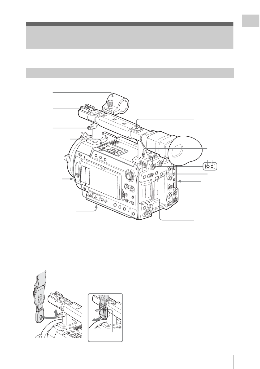
Camcorder
1
Overview
2
7
N
G
I
S
S
A
N 6
IG
P
O
C
T
E
ASS
S
R
/
T
R
A
T
S
3
Upper operation
block (page 16)
56
00
K
C
C
N
D
F
I
L
T
E
R
2
1
Side panel
(page 15)
OFF
S
H
U
T
T
O
E
FF
R
ON
M
H
Bottom (page 17)
1. Microphone holder (page 29)
2. Front accessory shoe
3. Post for the shoulder strap (left and right)
Attach the supplied shoulder strap as shown
below.
L
E
N
S
IN
F
O
B
R
T
D
IS
P
1
2
L
C
D
B
R
IG
L
C
D
B
O
N
G
A
IN
W
H
IT
B
E
A
L
LA
N
C
E
A
T
Z
W
E
B
B
A
P
R
S
T
To remove
B
A
R
S
/
C
A
M
T
H
U
M
F
B
R
N
E
A
V
I
L
P
j
L
A
Y
P
/
P
R
E
V
G
l
/
S
S
T
O
P
s
N
E
X
L
H
IS
T
O
G
R
A
M
A
S
S
IG
3
N
H
T
.L
IG
H
T
O
F
F
R
A
P
E
A
K
IN
G
S
T
ATU
S
A
U
S
E
J
T
TC/U-BIT/
DURATION
4
F
F
W
D
B
I
D
S
D
H
A
SDI OUT
Y
R
TE
T
A
E
L
B
S
E
A
C
N
A
LE
C
E
R
T
E
S
/
L
E
S
U
N
E
B
A
OFF
ON
T
C
E
L
E
S
OFILE
PICTURE PR
T
U
O
O
E
ID
V
TC IN
TC OUT
IN
K
C
O
L
N
E
G
S&Q
CH-1
DISPLAY/
BATT INFO
C
A
C
H
E
R
E
C
M
A
U
D
IO
LE
V
E
L
CH
-2
CH-1
AUDIO
SELECT
C
A
H-2
U
T
O
M
A
N
U
A
L
MONITOR
VOLUME
T
O
L
S
A
S
S
IG
N
5
IN
C
D
5
67
8
Rear panel
(page 16)
9
4. Rear accessory shoe
5. Headphone connector (stereo mini jack)
(page 54, page 83)
6. Rear tally lamp (page 36, page 139)
7. Rear IR remote control receptor
8. BATTERY RELEASE button (page 21)
9. Battery pack receptacle (page 21)
PRESS
Press the tab to
unlock.
Parts Identifications
13
Page 14
Overview
1
Operation block on the
handle (page 16)
2
3
4
5
H
D
M
I
O
U
6
REC START/
STOP
T
L
IN
K
(H
D
V
/D
V
)
R
E
M
O
T
E
S
P
A
R
E
R
E
C
R
E
V
I
E
W
E
X
P
A
F
N
O
D
C
E
U
D
S
W
T
7
8
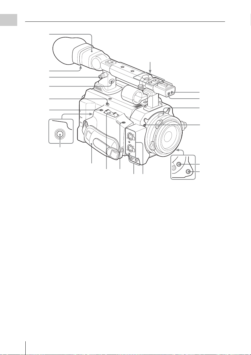
1. Viewfinder (page 26)
2. Eyepiece focusing knob (page 26)
3. Post for the shoulder strap (See the
previous page.)
4. Built-in speaker (page 54, page 83)
5. REC REVIEW button (page 57)
6. EXPANDED FOCUS button (page 49)
7. REC START/STOP button (page 36)
8. Grip belt
9. Servo zoom lever
It does not function at present.
10. ASSIGN 8 (assignable 8) button (page 58)
11. AUDIO OUT CH-1/CH-2 connectors
(RCA phono jacks) (page 124)
12. AUDIO IN CH-1/CH-2 connectors (XLR)
and input selection switches (page 53)
13. Front tally lamp (page 36, page 139)
14. Front IR remote control receptor
15. Lens mount (page 27)
S
T
A
R
T
/S
R
T
E
O
C
P
A
S
S
I
G
N
6
ASSIGN 7
T
T
L
L
X
X
E
E
N
N
P
P
J
J
D
O
O
W
T
T
F
S
S
F
S
S
/
/
E
ls
ls
S
V
V
U
G
G
E
E
A
R
R
P
/
P
P
Y
A
L
P
j
j
V
V
E
E
R
R
F
F
M
M
A
A
C
C
/
/
S
S
R
R
A
A
B
B
ASSIGN 8
A
U
D
C
I
O
H
I
-
N
1
M
I
C
L
I
N
E
C
M
H
I
C
-
2
+
4
8
V
M
I
C
L
I
N
E
M
I
C
+
4
8
V
C
H
-
1
A
U
D
I
O
O
U
T
C
H
-
2
109
1211
ASSIGN 4
AUTO
WHT BAL
16. Flange focal length adjustment screw
(page 28)
17. ASSIGN 4 (assignable 4) button (page 58)
18. AUTO WHT BAL (automatic white
balance adjustment) button (page 40)
13
14
15
16
17
18
Parts Identifications
14
Page 15
Side panel
Overview
1
LENS INFO
BRT DISP
ON
123
WHITE
BALANCE
L
ATW
B
M
A
PRST
H
2
3
4
5600K CC
ND FILTER
2
1
OFF
SHUTTER
OFF
56 78
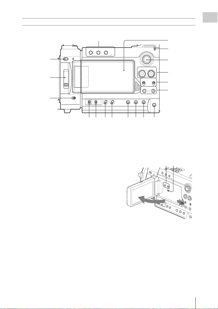
1. ASSIGN (assignable) 1/2/3 buttons (page
58)
2. 5600K CC (color compensation filter)
button with indicator (page 40)
3. ND FILTER switch (page 39)
4. SHUTTER switch (page 46)
5. GAIN switch (page 45)
6. WHITE BALANCE (white balance
memory) switch (page 40)
7. ZEBRA button (page 44)
8. PEAKING button (page 49)
9. STATUS button (page 94)
10. TC/U-BIT/DURATION (time data
selection) button (page 52, page 82)
11. DISPLAY/BATT INFO button (page 19,
page 22)
12. ASSIGN 5 (assignable 5) button (page 58)
13. MONITOR VOLUME buttons (page 54,
page 83)
14. AUDIO SELECT (audio level control
mode selection) switches (page 53)
15. AUDIO LEVEL CH-1 /CH-2 controls
(page 53)
16. S&Q (Slow & Quick Motion) dial (page
64)
17. CACHE REC lamp (page 63)
HISTOGRAM
ASSIGN
TC/U-BIT/
ZEBRAGAIN PEAKING STATUS ASSIGN 5
DURATION
S&Q
AUDIO
CH-1 CH-2
LEVEL
AUDIO
CH-1 CH-2
SELECT
AUTO
MANUAL
MONITOR
VOLUME
DISPLAY/
BATT INFO
CACHE
REC
91011 12
18. LCD (Liquid Crystal Display) monitor
(page 25)
The display is turned on when you unlock the
panel by pressing the tab to the right then
open it.
19 20
2
19. LCD BRIGHT +/– (LCD brightness
adjustment) buttons (page 25)
20. LCD B.LIGHT (LCD backlight) switch
(page 25)
18
17
16
15
14
13
L
C
D
B
R
IG
H
T
L
C
D
B
.L
IG
H
O
T
N
O
F
F
1
Parts Identifications
15
Page 16
Operation block on the handle
U
4
Overview
3
2
1
ASSIGN 6 ASSIGN 7
1. Protective cover (page 36)
2. ASSIGN 6/7 (assignable 6 and 7) buttons
(page 58)
3. REC START/STOP (recording start/stop)
button (page 36)
Upper operation block
REC
Rear panel
Operation block
1234
HD SDIAB
START/STOP
5
MENU SEL/SET CANCEL
AB
SLOT SELECT
ON OFF
DC IN
PICTURE PROFILE
BATTERY
RELEASE
2134
BARS/CAM F REV
THUMBNAIL
PLAY/PAUSE
j
PREV STOP NEXT
lsL
6578
1. BARS/CAM (color bar/camera signal
switching) button (page 55)
2. F REV (fast reverse) button (page 82)
3. PLAY/PAUSE button (page 82)
4. F FWD (fast forward) button (page 82)
5. THUMBNAIL button (page 78)
6. PREV (previous) button (page 82)
7. STOP button (page 82)
8. NEXT button (page 82)
Parts Identifications
16
G
/SJ
F FWD
1. MENU (menu display ON/OFF) button
(page 100)
2. SEL/SET (selection/set) dial (Jog dial)
(page 100)
It functions accordingly when you turn it up
or down, or you push it horizontally.
3. CANCEL button (page 100)
4. PICTURE PROFILE button (page 67)
5. Power switch and indicator (page 23)
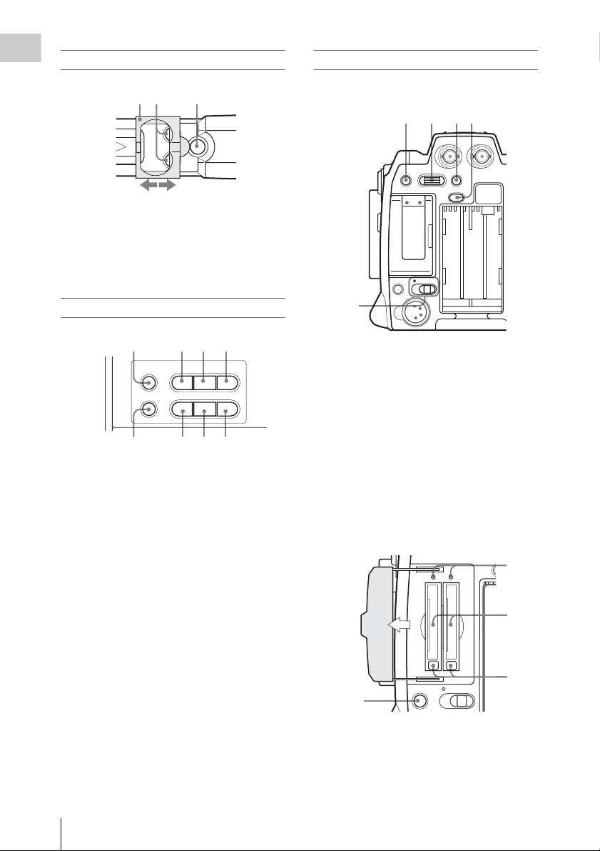
Card slot block
Open the cover to insert/remove SxS memory
cards.
AB
PICT
2
3
SLOT SELECT
ON OFF
1
1. SLOT SELECT (SxS memory card select)
button (page 34)
2. Access lamps (page 33)
3. SxS memory card slots (page 33)
4. Eject buttons (page 33)
Page 17
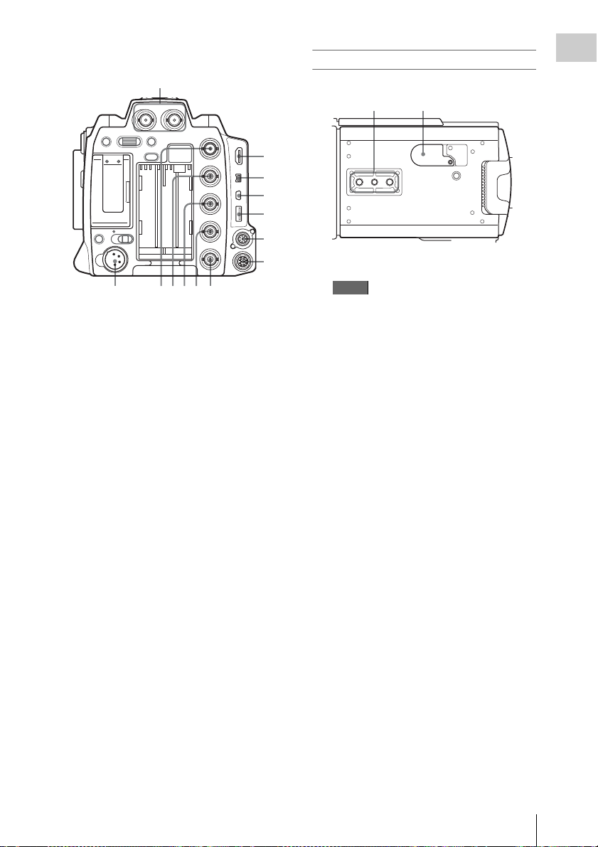
Connector block
1
HD SDIAB
Bottom
Overview
12
MENU SEL/SET CANCEL
AB
SLOT SELECT
ON OFF
DC IN
PICTURE PROFILE
BATTERY
RELEASE
SDI OUT
VIDEO OUT
TC IN
TC OUT
GENLOCK IN
234567
1. HD SDI A/B (Dual-Link) connectors
(BNC type) (page 125)
2. DC IN (DC power input) connector
(page 22)
3. SDI OUT connector (BNC type) (page 124)
4. VIDEO OUT (analog video output)
connector (BNC type) (page 124)
5. TC IN (timecode input) connector (BNC
type) (page 131)
6. TC OUT (timecode output) connector
(BNC type) (page 132)
7. GENLOCK IN connector (BNC type)
(page 131)
8. HDMI OUT connector (page 124)
9. i.LINK (HDV/DV) connector (4-pin, S400
conforming to IEEE1394) (page 128)
10. USB connector (Mini B) (page 125)
11. Option connector (USB type A)
It does not function at present.
12. REMOTE connector (8-pin)
An external remote control device, such as
the RM-B150/B750 Remote Control Unit,
can be connected.
For operation from the remote control device,
refer to the Supplement in the supplied CDROM labeled “Manuals for So lid-State Memory
Camcorder.”
13. SPARE connector (10-pin)
It does not function at present.
8
9
10
11
12
13
1. Tripod receptacles
Note
Check that the size of the hole matches the
screw of the tripod. If they do not match, the
camcorder cannot be attached to the tripod
securely.
2. Backup battery holder (page 135)
Parts Identifications
17
Page 18
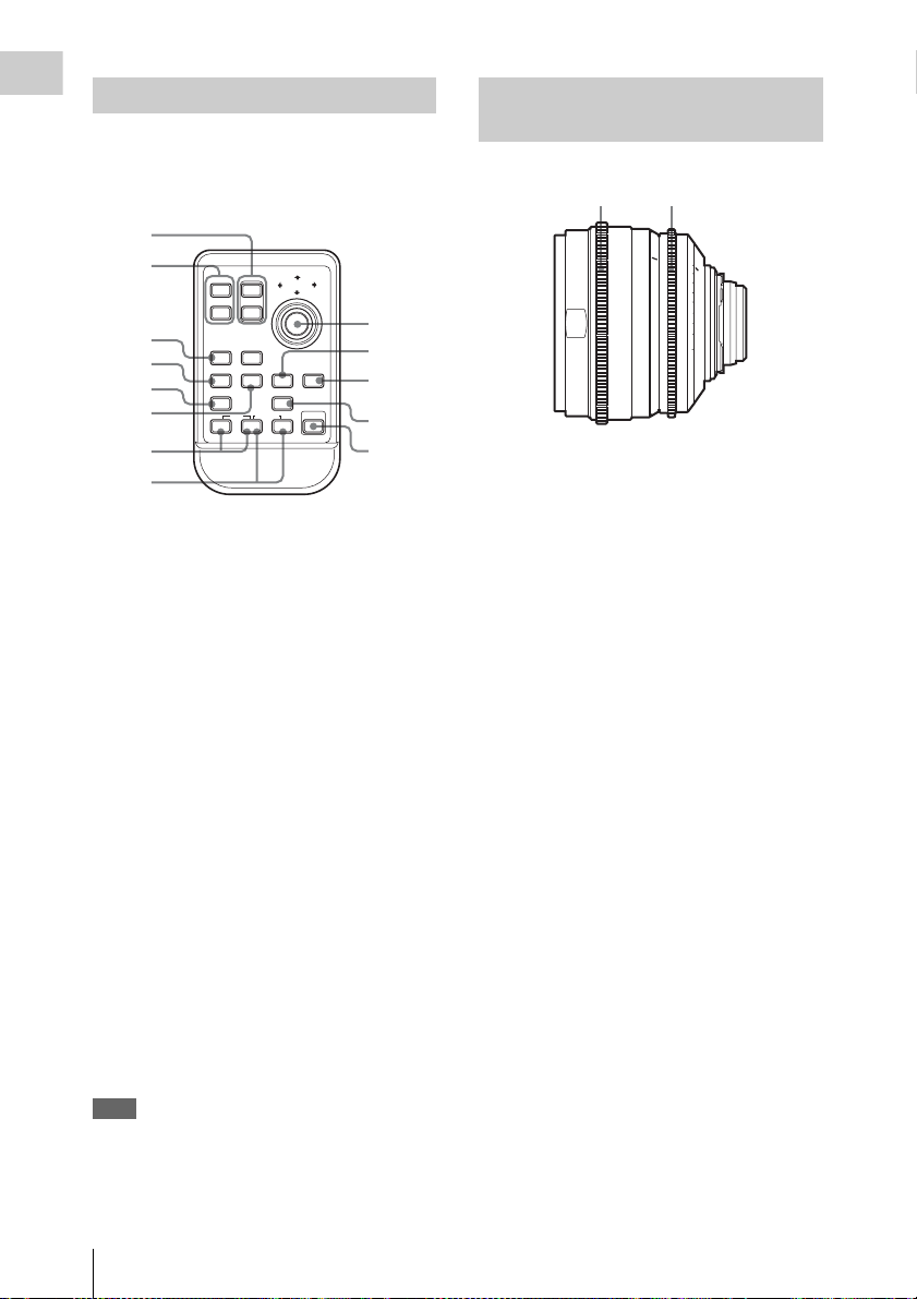
IR Remote Commander (Supplied)
Overview
The buttons without remarks can be used in the
same manner as the corresponding buttons on the
camcorder.
1
2
SHOTMARK
3
4
5
6
THUMBNAIL
PREV NEXT
.
m
12T
REC
z
ZOOM
W
SUB CLIP
PLAY/PAUSE
PUSH SET
STOP
>
xu
FFWDFREV
M
PUSH AFREC PAUSE
X
7
8
1. ZOOM T/W (telephoto/wide-angle)
button
It does not function at present.
2. SHOTMARK 1 and 2 buttons (page 56,
page 92)
3. THUMBNAIL button
4. PREV (previous clip jump) button
5. F REV (fast reverse) button
6. PLAY/PAUSE button
7. REC (record) buttons
Press the z button together with the unmarked
button (safety button) to start recording.
8. REC PAUSE buttons
Press the X button together with the unmarked
button (safety button) to pause recording.
9. PUSH SET button
It functions the s ame as the SEL/ SET dial on th e
camcorder.
10. NEXT button
11. STOP button
12. F FWD (fast forward) button
13. PUSH AF button
It does not function at present.
Note
The SUB CLIP button does not function with this
camcorder.
When you use the Remote Commander, see “Using
the IR Remote Commander” on page 30.
10
11
12
13
Lenses (Supplied with the PMWF3K)
12
ft
2
10
30 ft
2.8
4
5
5.6
15
8
10
1
1
7
9
50
The illustration shows the SCL-P50T20.
1. Focus ring
2. Iris ring
16
2
22
5
1.5 3
0
4
1.2
1
3.3
2.62
0.8
0.60.5
1.6
Parts Identifications
18
Page 19
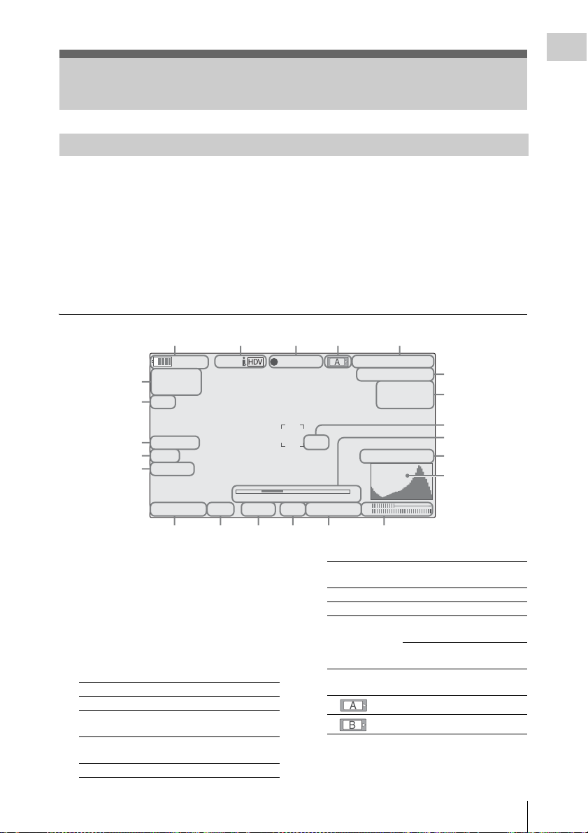
On-Screen Indications
7
8
9
0
2
Indications in E-E Display/Recording Mode
Overview
When this unit is in E-E Display1)/Recording
mode, pressing the DISPLAY/BATT INFO
button displays the statuses and settings of this
unit on the LCD monitor/viewfinder screen.
When you press the DISPLAY/BATT INFO
button again, these indications are canceled.
The recording status indication, such as “
is always displayed, regardless of operation of the
DISPLAY/BATT INFO button.
1)E-E Display mode: Recording standby status
zREC,”
12345
STBY
120min
A: 60min
6
B: 120min
7
Z99
8
5600K CC
9
ND1
10
TLCS
ATW 4300K
.
S&Q
1 1.5 2 3 4 5 7 10 15 20 30 oo
++
PPOFF
T1.6
11 12 13 14 15 16
1. Battery remaining/DC IN voltage
indication [M] (page 21)
2. i.LINK status indication (page 128)
Only when an external device is connected to
the i.LINK connector, the status of the device is
displayed.
3. Special recording/operation status
indication
zREC Recording in progress
STBY Standby for recording
zS&Q REC Slow & Quick Motion
S&Q STBY Standby for Slow & Quick
zINT REC Interval Recording in progress
recording in progress
Motion recording
Remarks
[M]: The indication of the items named with this
suffix can be independently turned on/off
with “Display On/Off” of the LCD/VF SET
menu (see page 111).
[A]: The indication of items named with this suf-
fix can be turned on/off using the assignable
buttons to which the corresponding on/off
functions have been assigned (see page 58).
REC
TCG 00:00:00:00
Q
1920/23.98P
H
Q M
otion
S&
29/24fps
74%
High Light ND2
m
CH1
18dB
SHT
CH2
:1/2000
INT STBY Standby for Interval
zFRM REC Frame Recording in progress
FRM STBY Standby for Frame Recording
zCACHE z in green: Standby for
Recording
Cache Recording
z in red: Cache Recording in
progress
4. Media status indication
5. Time data indication [M] (page 52)
6. Media remaining indication [M] (page 34)
Memory card in slot A is active.
Memory card in slot B is active.
2
21
2
1
1
1
On-Screen Indications
19
Page 20

7. Zoom position indication [M] (page 48)
STD
Overview
8. Electric color compensation filter
indication [M] (page 40)
9. ND filter indication [M] (page 39)
10. TLCS mode indication [M] (page 105)
Backlight mode
Standard mode
STD
Spotlight mode
11. White balance mode and color
temperature indications [M] (page 40)
12. Picture profile indication [M] (page 67)
13. Iris position indication [M] (page 48)
14. Gain indication [M] (page 45)
15. Shutter mode/shutter speed indication [M]
(page 46)
16. Audio level meters [M] (page 53)
17. Histogram indication [M][A]
18. Video level cautioning indication [M]
If the video level is too high or too low, a caution
is generated showing the appropriate ND filter
number.
19. Depth-of-Field indication [M][A]
20. Brightness level indication [M][A]
21. Special recording mode indication [M]
Frame Rec Frame Rec mode
Interval Rec Interval Rec mode
S&Q Motion
xx/xx fps
Slow & Quick Motion mode
22. Video Format indication [M] (page 37)
On-Screen Indications
20
Page 21

Preparations
Power Supply
You can use a battery pack or AC power via an
AC adaptor.
If you connect an AC power source, it has a
priority even if a battery pack is mounted.
For safety, use only the Sony battery pack and AC
adaptor listed below:
• BP-U60 Lithium-ion Battery Pack
• AC-DN10 AC Adaptor
Preparations
Battery pack
Using a Battery Pack
Mount a BP-U60 Lithium-ion Battery Pack.
WARNING
Batteries shall not be exposed to excessive heat
such as sunshine, fire or the like.
CAUTION
Danger of explosion if battery is incorrectly
replaced. Replace only with the same or
equivalent type recommended by the
manufacturer.
When you dispose of the battery, you must obey
the law in the relative area or country.
Notes
• Before use, charge the battery pack with the
exclusive BC-U1/U2 Battery Charger.
• A warm battery pack immediately after use may
not be able to be fully recharged.
Mounting the battery pack
Fully insert the battery pack then slide it down to
lock.
Power switch: OFF
Note
If a battery pack that cannot be used with this
camcorder is mounted, an error message is
appears on the LCD monitor/viewfinder screen.
Replace the battery pack with the BP-U60, or
connect a power to the DC IN connector after
removing the battery pack.
Removing the battery pack
Hold the BATTERY RELEASE button pressed,
slide the battery pack upwards to unlock, then
pull it out.
BATTERY RELEASE button
1
2
Power switch: OFF
Checking battery charge remaining
To check during operation
When recording or playback is in progress on the
battery pack, an icon to show the current battery
Power Supply
21
Page 22
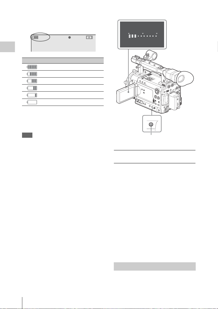
charge level and usage time remaining are
T
displayed on the LCD monitor/viewfinder screen.
120min
A: 25min
B: 50min
Z99
STBY
S&Q
REC
Preparations
Icon Remaining
100% to 91%
90% to 71%
70% to 51%
50% to 31%
30% to 11%
10% to 0%
BATTERY I NFO
0%
50%
Rem
aining Time : 20min
100
%
The camcorder indicates the remaining usage
time in minutes by calculating the available time
with the battery pack if operation is continued at
the current rate of power consumption.
Note
The operating time on a battery pack depends on
the condition (new or old) of the battery pack and
the ambient temperature.
To check in power-off status
Information on the mounted battery pack
(BATTERY INFO) is displayed on the LCD
monitor screen when you hold the DISPLAY/
BATT INFO button pressed even if the
camcorder is off.
The BATTERY INFO display goes off after 5
seconds.
DISPLAY/
BATT INFO
DISPLAY/BATT INFO button
If the battery charge remaining becomes
low
If the battery charge remaining decreases to a
certain level during operation (Low BATT
status), a low-battery message, flashing of the
tally lamps, and a beep sound will warn you.
If the remaining further decreases to a level at
which operation cannot be continued (BATT
Empty status), a battery-empty message appears.
Temporarily set the power switch to OFF and
connect a power source via the DC IN connector
or replace the battery pack with one that is fully
charged.
To change the message levels
The Low BATT level is set to 10% of full charge,
and the BATT Empty level is set to 3% of full
charge at the factory. These settings can be
changed with “Battery Alarm” (page 116) of the
OTHERS menu.
22
Power Supply
Using AC Power (DC IN Power)
The camcorder can be operated on AC power by
using an AC-DN10 AC Adaptor (optional) with a
CCDD-X2 DC Cable (optional).
Page 23

For details, refer to the Operating Instructions of the
AC-DN10.
When recording or playback is in progress on
power from the DC IN connector, the input
voltage is displayed on the LCD monitor/
viewfinder screen.
DC-IN 12.0V
A: 25min
B: 50min
Z99
STBY
S&Q
REC
Turning Power On
Set the power switch to the ON position.
The indicator (green) lights and the camcorder
enters E-E Display mode.
Setting the Area of Use and the Clock
When you turn the camcorder on for the first time
after purchasing or replacing the backup battery
(page 135), the Initial Setting display appears on
the LCD monitor/viewfinder screen.
Set the area of use and the date and time of the
built-in clock, using this display.
INITIAL
SETTING
C
ount r y : NTSC A r e a
Language
: English
Ti
me Zone: UTC GREENWICH
D
ate/Time: 2011/01/01 00:00:00
Finish
Language
You can select the language for messages.
When you select “Chinese,” the menus and status
indications are also displayed in Chinese.
Time Zone
The value shows the time difference from UTC
(Coordinated Universal Time).
Change the setting if needed.
Use the jog dial on the rear panel for setting.
Jog dial
Preparations
Power switch
ON OFF
Turning Power Off
Set the power switch to the OFF position.
Notes
• This camcorder uses a little standby power even
when the power switch is set to OFF. Remove
the battery pack if the camcorder will not be
used for a prolonged period.
• When removing the battery pack or the DC IN
power, be sure to set the switch to OFF in
advance and wait until the indicator goes dark.
Removing the battery pack or the DC IN power
while the indicator is lit may cause damage to
the camcorder or SxS memory cards.
MENU SEL/SET CANCEL
PICTURE PROF
AB
Setting the area of use
1 Turn the jog dial to set the cursor to
“Country” then press the dial.
Setting the Area of Use and the Clock
23
Page 24

2 Turn the jog dial to select the desired
area of use.
Setting Area of use
NTSC Area NTSC area (for areas other
than Japan)
NTSC area (Japan)
3)
PAL area
Preparations
NTSC(J) Area
PAL Ar ea
1) The composite signal output from this
camcorder is an NTSC signal with a black setup
(7.5 IRE). The system frequency is 59.94i.
2) The composite signal output from this
camcorder is an NTSC signal with no black
setup. The system frequency is 59.94i.
3) The composite signal output from this
camcorder is a PAL signal. The system
frequency is 50i.
Setting the time and date
1 Turn the jog dial to set the cursor to
“Date/Time” then press the dial.
The cursor moves to the year-setting column.
INITIAL
SETTING
C
ount r y : NTSC(J)
Language
:
Time Z
one: UTC +09:00 TOKY
D
ate/Time: 2011/01/01 00:00:00
Finish
Area
Japanese
2011/01/01 00:00:00 SET
For details on menu operations, see “Basic Menu
Operations” on page 100.
Notes
• If the clock setting is cleared because of
1)
2)
exhaustion of the backup battery while no
operation power was being supplied (no battery
pack and no DC IN connection), the Initial
Setting display will be displayed when you turn
the camcorder on at the next opportunity.
• While the Initial Setting display is shown, no
other operation except turning the power off is
permitted until you finish the setting for this
display.
O
2 Turn the jog dial to set the year then
press the dial.
The cursor moves to the month-setting
column.
3 Set the month, day, hour, minute, and
second in sequence in the same manner.
When you press the jog dial at “SET,” the
cursor moves back to “Date/Time.”
To finish the setting
Move the cursor to “Finish” then press the jog
dial.
The Initial Setting display disappears, and the
clock setting is completed.
Once after the Initial Setting display disappears,
the time zone and date/time settings can be
changed using the OTHERS menu (page 115).
Setting the Area of Use and the Clock
24
Page 25
Adjusting the LCD Monitor and Viewfinder
subject. The display direction of the textual
information is converted to the readable direction.
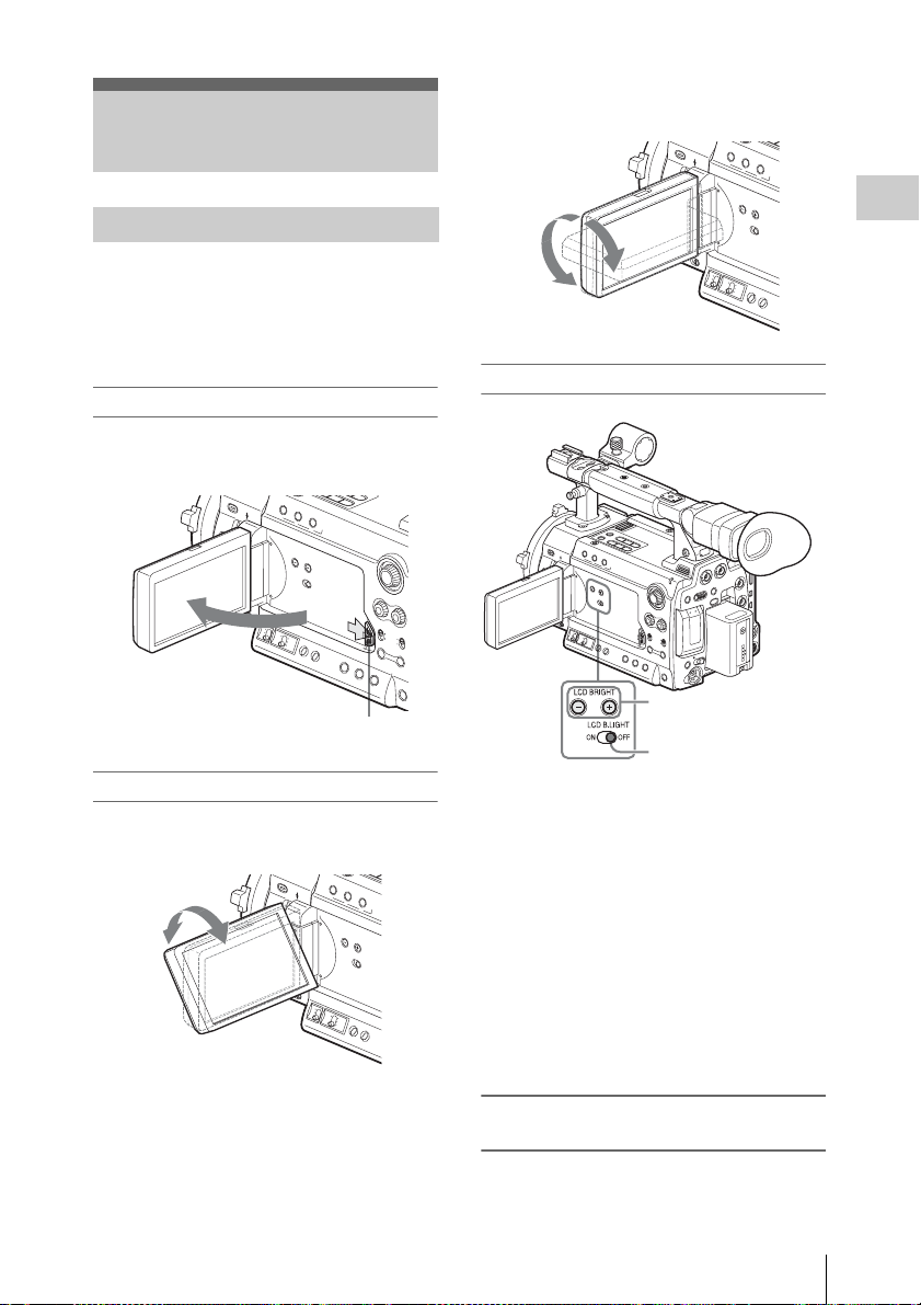
Adjusting the LCD Monitor
You can adjust the angle and the display
conditions of the LCD monitor for the best view
in various shooting situations.
These adjustments of the LCD monitor have no
effect on pictures being recorded.
Turning on/off the LCD monitor
The LCD monitor turns on when it is opened and
turns off when it is closed.
Press the tab to the right to unlock.
Adjusting the angle
Rotate the opened LCD monitor to the desired
angle.
90°
180°
Adjusting the backlight
LCD BRIGHT +/
LCD B.LIGHT switch
Turning the backlight on/off
The backlight may not be necessary for viewing
images on the LCD monitor under bright ambient
light, such as in an outdoor location. Set the LCD
B.LIGHT switch to OFF to turn off the backlight.
Adjusting the brightness of the backlight
When you set the LCD B.LIGHT switch to ON,
you can adjust the brightness of the backlight,
using the LCD BRIGHT + and – buttons.
Press the – button to darken the backlight. Press
the + button to make it brighter.
During adjustment, the backlight level bar
appears to indicate the adjustment value.
– buttons
Preparations
It can be rotated as much as 180 degrees in the
direction facing the subject and as much as 90
degrees in the opposite direction.
When you rotate it exceeding 135 degrees toward
the subject, the image on the monitor becomes
upside down, indicating the mirror image of the
Adjusting the color, contrast, and
brightness
These adjustments can be made using the LCD/
VF SET menu.
Adjusting the LCD Monitor and Viewfinder
25
Page 26

Press the MENU button to set the camcorder to
Menu mode and select (LCD/VF SET
menu) then “LCD” from the menu.
LCD/VF
SET
On/Off
B
C
olor
B
C
ont rast
B
Br i gh t ness
B
B
B
: 0
:
:
:
Preparations
00:00
LCD
VF
Peaking
M
arker
Zebra
Display
Set color, contrast and brightness of the LCD
monitor with the corresponding LCD menu
items: Color, Contrast, and Brightness
For details on menu operations, see “Basic Menu
Operations” on page 100.
Adjusting the Viewfinder
If the picture on the LCD monitor is hard to view
under bright ambient light, you can use the
viewfinder to check the picture.
You can adjust the display conditions of the
viewfinder according to your current lighting
conditions.
These adjustments of the viewfinder have no
effect on pictures being recorded.
Caution
Do not leave the camcorder with the eyepiece of
the viewfinder facing the sun. Direct sunlight can
enter through the eyepiece, be focused in the
viewfinder, and cause fire.
Turning the viewfinder on/off
With the factory setting, the viewfinder is turned
on when the LCD monitor is in its park position
or is rotated to face the subject.
You can change the setting so that the viewfinder
is always on regardless of the status of the LCD
monitor, using “VF” (page 110) of the LCD/VF
SET menu. Change the “Power” setting from
“Auto” to “On.”
Adjusting the focus in the viewfinder
The eyepiece focusing (diopter compensation)
knob enables adjustment to match the eyesight of
operator so that the operator can view the image
clearly in the eyepiece.
Eyepiece focusing knob
0
0
0
Adjusting the backlight
The brightness of the backlight for the viewfinder
can be switched between High and Low.
Select “VF” from the LCD/VF SET menu and set
“Backlight.”
LCD/VF
SET
On/Off
B
Backl i ght
B
M
ode
B
C
ontrast
B
Br i g htness
B
Pow
er
B
:
:
:
:
:
High
Color
0
0
Auto
00:00
LCD
VF
Peaking
M
arker
Zebra
Display
Switching between color and
monochrome modes
For the viewfinder screen, color or monochrome
display can be selected.
Select “VF” from the LCD/VF SET menu then
select “Mode.”
Select “B&W” if checking the subject and
focusing are easier on the monochrome display.
If you assign “VF Mode” to one of the assignable
buttons (see page 58), you can switch between
color and monochrome by pressing the button.
Adjusting the contrast and brightness
Select “VF” from the LCD/VF SET menu and
adjust the contrast and brightness with the
corresponding items: Contrast and Brightness
For details on menu operations, see “Basic Menu
Operations” on page 100.
Adjusting the LCD Monitor and Viewfinder
26
Page 27
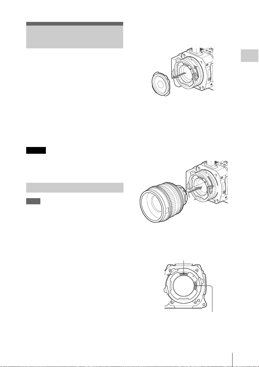
Attaching a Lens
1 Turn the lens mount frame
counterclockwise and remove the
mount cap from the lens mount.
Usable lenses
The following lenses are supplied with the PMWF3K.
• SCL-P35T20 (focal length: 35mm)
• SCL-P50T20 (focal length: 50mm)
• SCL-P85T20 (focal length: 85mm)
In addition to equivalents of the lenses supplied
with the PMW-F3K, various PL-mount lenses
can be used with the PMW-F3K/F3L.
For other lenses usable with the PMW-F3K/F3L, ask
a Sony service representative.
For information on handling lenses, refer to the
operation guide of the lenses.
Caution
Do not leave the camcorder with the lens facing
the sun. Direct sunlig ht can enter through the lens,
be focused in the camcorder, and cause fire.
Attaching a Lens
Notes
• Turn off the camcorder before attaching/
removing the lens.
• The camera interface of the camcorder is set to
“Type C” for the lenses supplied with the
PMW-F3K and those having a Cooke
connector. When attaching a lens with an
1)
connector (usable in the future), set the
ARRI
interface to “Type A” with “Lens IF” (page
106) of the CAMERA SET menu. Or set it to
“Off” for other lenses.
If the interface setting is not correct, a warning
message will be displayed when you turn on the
camcorder.
For details on menu operations, see “Basic Menu
Operations” on page 100.
Preparations
2 Align the recess of the lens with the
alignment pin at the upper part of the
lens mount of the camcorder and set the
lens in place.
3 While holding the lens, turn the lens
mount frame clockwise to secure the
lens.
3
2
When using an ARRI LDS lens or a Cooke /i lens,
align the contacts of the lens with the
corresponding hot shoe of the camcorder.
Hot shoe for Cooke /i lenses
1)ARRI Group
Hot shoe for ARRI LDS lenses
Attaching a Lens
27
Page 28
If you have attached an aberration correction
lens
The aberration correction function is activated
automatically. Starting the camcorder with an
aberration correction lens may require more time
than normally because of data loading at start-up.
The lenses supplied with the PMW-F3K are
Preparations
aberration correction lenses.
Contact a Sony service representative for
information about other aberration correction
lenses.
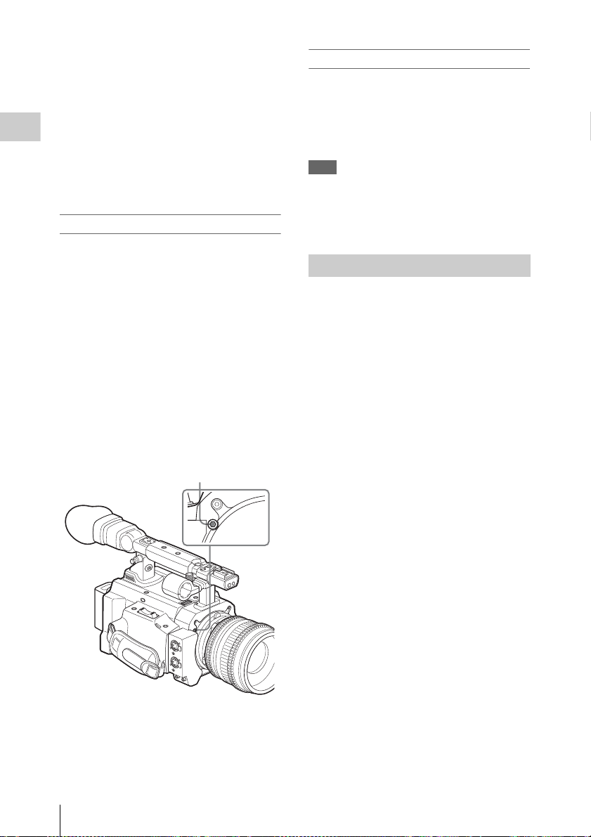
Adjusting the flange focal length
Adjustment of the flange focal length (distance
between the lens mount attachment plane and the
imaging plane) is necessary in the following
situations:
• The first time a lens is attached
• When changing lenses
• If the focus is not sharp at both telephoto and
wide angle with a zoom lens
The flange focal length for this camcorder can be
adjusted by rotating the adjustment screw.
Use an Allen wrench (sized 7/64 inch) for the
adjustment.
Counterclockwise rotation lengthens the flange
focal length and clockwise rotation shortens it.
Removing the lens
Proceed as follows:
1 While holding the lens, turn the lens
mount frame counterclockwise.
2 Pull the lens forward to remove.
Note
When another lens is not immediately attached,
attach the lens mount cap to its original position
and secure it by turning the lens mount frame
clockwise.
Using Lens Files
By your storing the data (such as compensation
data) specific to the lenses in files, required
adjustments and compensation can be performed
merely by retrieving the appropriate file when
changing lenses.
For details on the lens files, see “Lens Files” on
page 122.
Attaching a Lens
28
Adjustment screw of flange focal length
D
W
F
F
E
S
U
A
P
/
Y
A
L
P
Page 29
Attaching the
P
L
A
Y
/P
A
U
S
E
F
F
W
D
P
L
A
Y
/P
A
U
S
E
F
F
W
D
Microphone
Two channels (CH-1/CH-2) of audio can be
recorded (Linear PCM recording) in
synchronization with video recording.
Cable clamp
U
L
P
R
1
2
Preparations
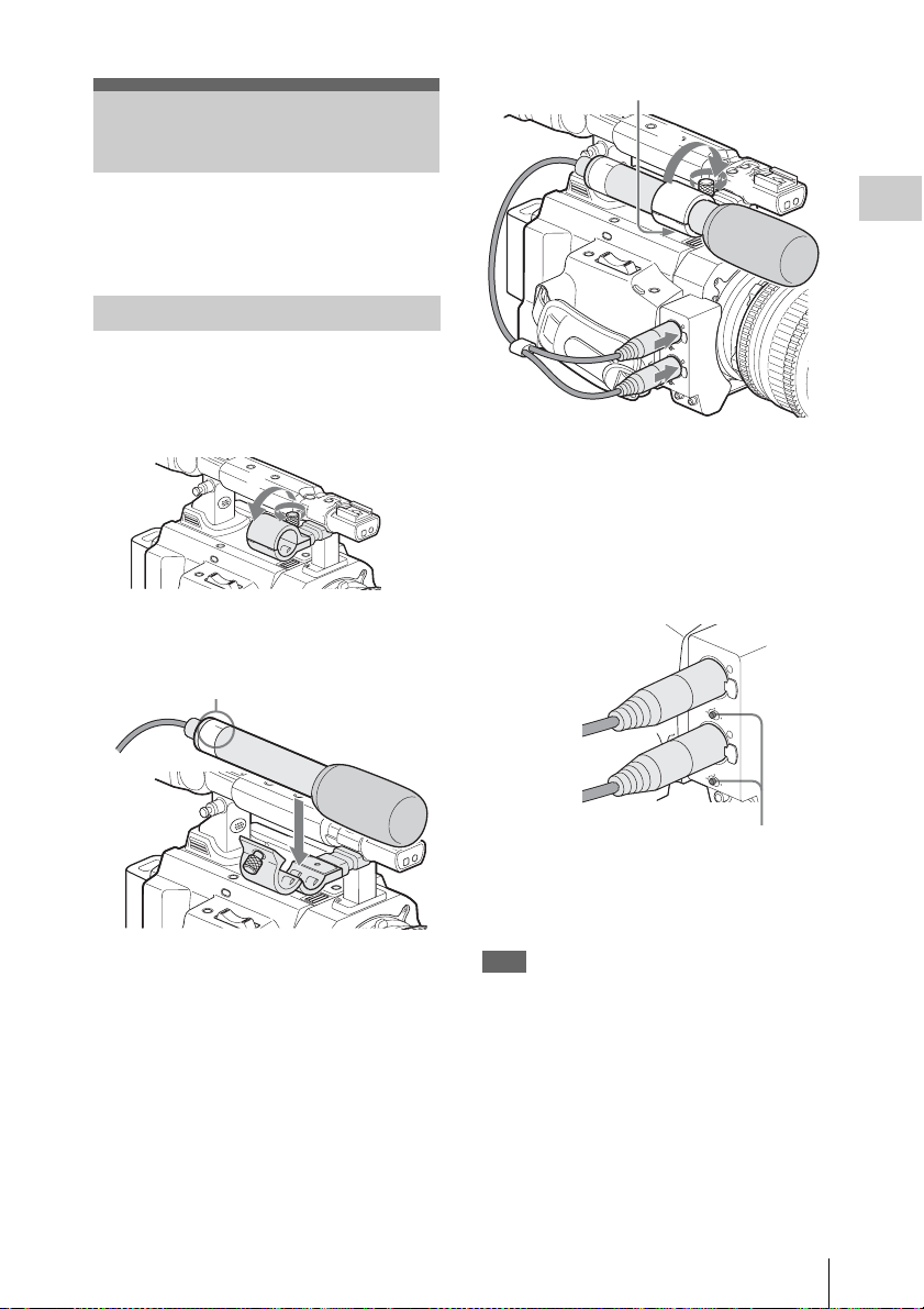
Using the Supplied Microphone
Attach the microphone as follows:
1 Loosen the screw of the microphone
holder and open the cover.
2
1
2 Set the microphone on the holder with
the UP indication facing up.
UP
U
L
P
R
3 Close the microphone holder cover for
the original condition to secure, then
connect the microphone cable to the
AUDIO IN connectors (CH-1 and CH-
2) and secure the cable at the cable
clamp under the holder.
3
Connect the white plug of the supplied
microphone to the CH-1 connector of the
camcorder and the red plug to the CH-2
connector.
4 Set the LINE/MIC/MIC+48V switches
(CH-1 and CH-2) to MIC+48V.
AU
D
IO
C
IN
H
-1
M
IC
LINE
C
H
M
-2
IC+48V
M
IC
LIN
E
M
IC
+48V
LINE/MIC/MIC+48V switch
5 Set “EXT CH Select” of “Audio Input”
(page 106) of the AUDIO SET menu to
“CH-1/CH-2.”
Note
Even when recording CH-1 for 2-channel
monaural by setting “EXT CH Select” of “Audio
Input” (page 106) of the AUDIO SET menu to
“CH-1,” set the LINE/MIC/MIC+48V switch for
CH-2 to the same position as that for CH-1.
However, if a microphone which supports both
stereo and monaural modes is connected and
power of +48 V is supplied to CH-2, the
microphone is not switched to monaural mode,
but the directivity goes the left channel side. For
such a microphone, set the LINE/MIC/MIC+48V
Attaching the Microphone
29
Page 30

switch for CH-1 to MIC+48V and that for CH-2
to MIC.
Sony-made microphones which support both
stereo and monaural modes
• Microphone supplied with this camcorder
•ECM-680S
Preparations
Using External Inputs or Optional Microphones
Connect external audio sources or external
microphones to the AUDIO IN connectors CH-1
and CH-2, then set the LINE/MIC/MIC+48V
switches CH-1 and CH-2 to the appropriate
position.
LINE: For audio a audio line source (Line level:
+4 dBu)
MIC: For a microphone that requires no power
supply
MIC+48V: For a microphone that requires +48V
power supply
Using the IR Remote Commander
Before use
Before you use the supplied IR Remote
Commander for the first time, pull out the
insulation sheet from the battery holder.
Insulation sheet
A CR2025 lithium battery is set in the holder at
the factory.
To use the IR Remote Commander
For controlling the camcorder from the IR
Remote Commander, activate the remote control
function of the camcorder after turning the power
on.
Activating/deactivating the remote control
function can be achieved using the Setup menu or
an assignable button.
To activate using the menu
Press the MENU button to set the camcorder to
Menu mode, select (the OTHERS menu)
and set “IR Remote” to “On.”
Using the IR Remote Commander
30
O
THE
RS
:
Button
eter
: O
Alar
B
B
B
B
B
m
English
O
n
n
Off
B
C
lock Set
Language
Assign
Tal l y
00:00
H
ours M
IR Remote
Battery
For details on menu operations, see “Basic Menu
Operations” on page 100.
To activate using an assignable button
Assigning “IR Remote” to one of the assignable
buttons permits you to activate/deactivate the
remote control function by pressing the button.
For the assignable buttons, see“ Changing Functions
of the Assignable Buttons” on page 58.
Page 31

Note
1
To avoid malfunctions, the remote control
function is automatically deactivated when the
camcorder is turned off. Activate the function
each time when required after you turn the
camcorder on.
Battery lifetime
When the lithium battery’s power falls, the IR
Remote Commander may not work even if you
press the buttons. The average lithium battery’s
service life is about one year, but this depends on
the pattern of use.
If pressing the remote control buttons produces
absolutely no effect on the camcorder, replace the
battery then check the operation again.
Replacing the battery in the IR Remote
Commander
Use a commercially available CR2025 lithium
battery. Do not use any battery other than a
CR2025.
1 Hold down the lock lever 1, pull out
the battery holder 2, and remove the
battery.
WARNING
• Battery may explode if mistreated.
Do not recharge, disassemble, or dispose of in
fire.
• Batteries shall not be exposed to excessive heat
such as sunshine, fire or the like.
CAUTION
Danger of explosion if battery is incorrectly
replaced. Replace only with the same or
equivalent type recommended by the
manufacturer.
When you dispose of the battery, you must obey
the law in the relative area or country.
Preparations
2
2 Place a new battery in the battery
holder with the + symbol facing upward
1, then push the battery holder into th e
IR Remote Commander until it clicks
2.
With the + symbol upward
1
2
Using the IR Remote Commander
31
Page 32

Handling SxS Memory Cards
This camcorder records audio and video on SxS
Preparations
memory cards (optional) inserted in the card slots.
About SxS Memory Cards
Usable SxS memory cards
Use the following Sony-made SxS memory cards
(SxS PRO or SxS-1) with this camcorder.
Operations are n ot guaranteed with memory cards
other than SxS PRO and SxS-1.
SxS PRO
• SBP-16 (16GB)
• SBP-32 (32GB)
SxS-1
• SBS-32G1A (32GB)
• SBS-64G1A (64GB)
These cards comply with the ExpressCard
standard.
• SxS, SxS PRO and SxS-1 are trademarks of Sony
Corporation.
• The ExpressCard word mark and logo are owned by
Personal Computer Memory Card International
Association (PCMCIA) and are licensed to Sony
Corporation. All other trademarks are the property of
their respective owners.
Notes on using SxS memory cards
• Recorded data may be damaged or lost in the
following situations:
—If you remove this media or turn off the
power while formatting, reading or writing
data.
—If you use this media in locations subject to
static electricity or electrical noise.
• Do not use or store this media in the following
locations:
—Where recommended operating conditions
are exceeded.
—Inside a closed car in summer; or in strong
sunshine / under direct sunlight / near a
heater, etc.
—Humid or corrosive location
• Verify the correct direction of insertion before
use.
• When storing or carrying this media, put this
media in the carrying case and lock it firmly.
• We recommend that you make a backup copy of
important data. Sony accepts no responsibility
for any damage or loss of data you recorded.
• Do not apply a label sheet in places other than
the label space. When applying the label sheet
to this media, do not allow it to protrude from its
proper location.
Label space
• SxS memory cards to be used with this
camcorder must be formatted using the format
function of this camcorde r. If a card is formatted
using other device, it is regarded as of a
different format, requiring repeated format
operation on this camcorder.
• Deleting with the function of the camcorder
does not completely delete data on this media.
When transferring or disposing of this media,
use a commercial data deleting software or
destroy the actual body at you own
responsibility.
• If the available recording time on a card is short,
clip operation may be restricted. In such a case,
delete unnecessary files by using a PC.
• Remove or reinsert the case card with the case
opened properly.
For write protection
Setting the write-protect switch of the SxS
memory card to “WP” disables you to record, edit
or delete data.
Handling SxS Memory Cards
32
Page 33

Write-protect switch
MENU
SEL/SET
CAN
O
N
S
L
O
T
S
E
L
E
C
T
O
FF
PICTURE P
A
B
D
C
IN
MENU
SEL/SET
CAN
O
N
S
L
O
T
S
E
L
E
C
T
O
FF
PICTURE P
A
B
D
C
IN
Note
Do not operate the write-protect switch of an SxS
memory card while it is set in the camcorder.
Temporarily remove the card from the camcorder
before changing the switch setting.
2 Insert the SxS memory card into the
slot.
Preparations
With the label facing right
Inserting/Removing an SxS Memory Card
AB
SLOT SELECT
SLOT SELECT button
Cover
ON OFF
Access lamps
Card slots
Eject buttons
The access lamp lights in red then changes to
green once the memory card is ready for use.
3 Close the cover.
Status indications by the access lamps
Card slots A and B are accompanied by the
respective access lamps to indicate their statuses.
Lamp Slot statuses
Lights in
red
Lights in
green
Off • No SxS memory card is loaded.
Accessing the loaded SxS memory card
(writing/reading data)
Standby (ready for recording or
playback using the loaded SxS memory
card)
• The loaded card is invalid.
• An SxS memory card is loaded, but
another slot is active.
Removing an SxS memory card
1 Open the cover, once press the eject
button to release the lock, then pull the
button out.
Inserting an SxS memory card
1 Open the cover.
Press and unlock the button.
Handling SxS Memory Cards
33
Page 34

2 Press the eject button again to remove
MENU
SEL/SET
CAN
SLOT SELECT
O
N
O
F
F
PICTURE P
A
B
D
C
IN
T
the card.
Preparations
Notes
• Data are not guaranteed if the power is turned
off or a memory card is removed while the card
is being accessed. All data on the card may be
destroyed. Be sure that the access lamps are lit
in green or off when you turn off the power or
remove memory cards.
• Fully insert the memory card in the card slot. If
it is inserted halfway, the eject button may not
function properly.
Switching Between SxS Memory Cards
When SxS memory cards are loaded in both card
slots A and B, press the SLOT SELECT button to
select the card you wish to use.
If a card becomes full during recording, switching
to the other card is automatically executed.
Note
The SLOT SELECT button is disabled while
playback is in progress. Switching is not executed
even if you press the button. The button is enabled
on the thumbnail screen (page 78).
Formatting an SxS Memory Card
Formatting may be required before using an SxS
memory card with this camcorder. For an SxS
memory card that is not formatted or that was
formatted with another system, the message
“Unsupported File System” is displayed on the
LCD monitor/viewfinder screen.
Format the card as instructed below.
2
1
Note on formatting
Any SxS memory card formatted with a device
other than this camcorder cannot be used with the
camcorder.
To execute formatting
Using “Format Media” (page 119) of the
OTHERS menu, specify “Media(A)” (slot
A) or “Media(B)” (slot B) then select
“Execute.”
Formatting begins.
The in-progress message and status bar (%) are
displayed, and the access lamp lights in red.
When formatting is completed, the completion
message is displayed for three seconds.
Recording/playback during formatting
You can perform recording or playback using the
SxS memory card in the other card slot while
formatting is in progress.
If formatting fails
A write-protected SxS memory card or memory
card that cannot be used with this camcorder will
not be formatted.
As a warning message is displayed, replace the
card with an appropriate SxS memory card, as per
the instructions in the message.
Notes
• All the data, including recorded pictures and
setup files, are erased when a memory card is
formatted.
• SxS memory cards to be used with this
camcorder must be formatted using the format
function of this camcorder. Any card formatted
with other device must be formatted again with
this camcorder.
Checking the Remaining Time Available for Recording
In E-E Display/Recording mode, you can check
the time remaining for the SxS memory cards
loaded in the card slots on the LCD monitor/
viewfinder screen.
120min
A: 25min
B: 50min
Z99
STBY
STBY
Handling SxS Memory Cards
34
Page 35

The available time for recording with the current
video format (recording bit rate) is calculated
according to the remaining space of each card and
displayed in time units of minutes.
The remaining can also be checked in a meter
format on the BATTERY/MEDIA status screen
(page 98).
Note
A icon appears if the memory card is writeprotected.
Replacing an SxS memory card
• If the available time on two cards in total
becomes less than 5 minutes, a message “Media
Near Full,” flashing of the tally lamps, and a
beep sound will warn you. Replace the cards
with those with sufficient space.
• If you continue recording until the total
remaining time reaches zero, the message
changes to “Media Full,” and recording stops.
Note
Approximately 600 clips can be recorded on one
SxS memory card at maximum.
If the number of recorded clips reaches the limit,
the remaining time indication becomes “0,” and
the message “Media Full” is displayed.
Restoring an SxS Memory Card
If an error occurs with data in a memory card for
some reason, the card must be restored.
If an SxS memory card that needs to be restored
is loaded, a message that prompts you to execute
a restore operation is displayed on the LCD
monitor/viewfinder screen.
such a card, a warning message is displayed.
Release the write protection or replace the card,
as per the instructions in the message.
• An SxS memory card on which an error
occurred may become usable again through
repeated formatting.
• In some cases, only parts of clips cannot be
restored. Playback of the restored clips becomes
possible again.
• The following operation may restore an SxS
memory card for which the message “Could not
Restore Some Clips” is repeatedly displayed
each time you try the restoration process:
1 Copy necessary clips to another SxS memory
card, using the copy function (page 88) of the
camcorder or the dedicated application
software (supplied) (page 127).
2 Format the problem SxS memory card, using
the format function of this camcorder.
3 Return the necessary clips to the SxS
memory card by copy operation.
Recording/playback during restoration
You can perform recording or playback using the
SxS memory card in the other card slot while
restoration is in progress.
Note
For restoration of media recorded with this unit,
be sure to use this unit. Media recorded with a
device other than this unit or with another unit of
different version (even of the same model) may
not be restored using this unit.
Preparations
To restore a card
Select “Execute” by turning the jog dial
then press the dial.
The restore operation begins.
During restoration, the in-progress message and
status bar (%) are displayed, and the access lamp
is lit in red.
When restoration is completed, the completion
message is displayed for three seconds.
If restoration fails
• A write-protected SxS memory card or one on
which an error occurred cannot be restored. For
Handling SxS Memory Cards
35
Page 36

Recording
Basic Operation Procedure
Basic recording can be performed with the
following procedures:
Preparations
1 Mount a fully charged battery pack.
2 Load SxS memory card(s).
Recording
If you load two cards, recording is continued
by automatically switching to the second
card when the first card becomes full.
3 Adjust the angle of the LCD monitor for
the best view.
When you wish to use the viewfinder, fold
the LCD monitor to its park position and
adjust the angle of the viewfinder.
4 Set the power switch to ON.
The camcorder is turned on.
When using the Remote Commander, activ ate the remote
control mode (page 30).
Note
When you hold the camcorder by the grip,
support it from underneath with your left hand.
Recording
8 To stop recording, press the REC
START/STOP button again.
(If you are using the IR Remote Commander, press
the REC PAUSE button simultaneously with the
unmarked button.)
Recording stops and the camcorder enters
STBY (recording standby) mode.
Note
If you press the REC START/STOP button to
start next recording while previous data writing is
not completed, the message “Cannot Proceed”
may be displayed and recording may not start.
To record external input signals
Changing the “Input Source Select” setting of the
VIDEO SET menu from “Camera” (factory
setting) to “i.LINK” en ables recording of an HDV
stream fed via the i.LINK (HDV/DV) connector.
For details, see “Recording External Input Signals”
on page 129.
To prevent a switching error
The REC START/STOP button on the handle is
incorporated with a protective cover. If the REC
START/STOP button on the handle will not be
used, it is recommended to cover the button.
Checking the last recorded clip (Rec
Review)
5 Adjust the iris, gain, electric shutter,
and white balance, as required.
See “Adjusting the Iris” on page 48,
“Setting the Gain” on page 45,
“Setting the Electronic Shutter” on page 46,
“Adjusting the White Balance” on page 40.
6 Focus on the subject.
7 Press the REC START/STOP button on
the handle or the grip.
(If you are using the IR Remote Commander, press
the REC button simultaneously with the unmarked
button.)
The front and rear tally lamps light and
recording begins.
Basic Operation Procedure
36
9 Press the REC REVIEW button.
The Rec Review function (page 57) is
activated, and the last recorded clip is played
back for the specified time on the LCD
monitor/viewfinder screen.
When playback reaches the end of the clip,
the camcorder returns to STBY (recording
standby) mode.
To delete clips
You can delete the last recorded clip by using the
Last Clip DEL function.
See“Deleting the Last Recorded Clip” on page 77.
Use the All Clips DEL function when you wish to
delete all recorded clips from a memory card.
Page 37

See“Deleting Clips Collectively” on page 77.
To specify a clip to be deleted, use the thumbnail
screen.
See“Deleting Clips” on page 89.
Clip (recording data) and clip name
When you stop recording, video, audio and
subsidiary data from the start to end of the
recording are recorded as a single clip on an
SxS memory card.
For each clip recorded with this camcorder, a
clip name composed of 4 to 46 alphanumerics
and 4 numerics is automatically generated.
Example: ABCD0001
The block of 4 to 46 alphanumerics can be
specified as desired using “Clip” (page 119) of
the OTHERS menu before you start recording.
(It cannot be changed after recording.)
The value of the 4 numerics is automatically
counted up in sequence.
Notes on Clips
The XDCAM EX-series products limit the
maximum file size of an HD clip to 4GB and
that of an SD clip to 2GB. If you continue
recording for an extended period, recorded
materials may be segmented into multiple files,
depending on the file size (the maximum
number of partitions is 99). The camcorder
regards continuous recording as one clip even if
it has been segmented into multiple files.
A long clip can be recorded crossing over two
memory cards in slot A and B.
When you copy clips to a hard disk drive, etc.
using a computer, it is recommended to use the
dedicated application software on the supplied
CD-ROM.
Note
If copying is done using Explorer (Windows)
or Finder (MAC), the continuity and
relationships of recorded materials may not be
maintained.
Maximum duration of a clip
In HD mode, a clip can be 24 hours long at
maximum. If a clip exceeds 24 hours, it is
automatically divided.
Selecting the Video Format
You can select various video formats for
recording/playback using “System” of the
OTHERS menu.
The current format is displayed on the screen
when you press the DISPLAY/BATT INFO
button.
REC
Selectable Formats
The selectable format s vary depending on HD/SD
setting and the area of use (NTSC or PAL).
Selection of the area of use is achieved on the Initial
Setting display (page 23) or using “System” (page
118) of the OTHERS menu.
HD mode
When the camcorder is set to HD mode, the video
formats set on this camcorder cover the recording
bit rate (HQ/SP), recording picture size
(horizontal resolution), recording frame rate, and
recording scan system (i/P).
When you select an HQ format, recording is made
with the bit rate of 35 Mbps VBR.
When you select an SP format, recording is made
with the HDV-compatible bit rate of 25 Mbps
CBR.
With “NTSC Area” or “NTSC(J) Area” selected
Format Indication on this
HQ 1920 × 1080
59.94 interlace
HQ 1920 × 1080
29.97 Progressive
HQ 1920 × 1080
23.98 Progressive
HQ 1440 × 1080
59.94 interlace
HQ 1440 × 1080
29.97 Progressive
TCG 00:00:00:00
Q
1920/59.94i
H
Q M
otion
S&
camcorder
HQ 1920/59.94i
HQ 1920/29.97P
HQ 1920/23.98P
HQ 1440/59.94i
HQ 1440/29.97P
Recording
Selecting the Video Format
37
Page 38

Format Indication on this
camcorder
Recording
HQ 1440 × 1080
23.98 Progressive
SP 1440 × 1080
59.94 interlace
SP 1440 × 1080
23.98 Progressive
HQ 1280 × 720
59.94 Progressive
HQ 1280 × 720
29.97 Progressive
HQ 1280 × 720
23.98 Progressive
HQ 1440/23.98P
SP 1440/59.94i
SP 1440/23.98P
HQ 1280/59.94i
HQ 1280/29.97P
HQ 1280/23.98P
With “PAL Area” selected
Format Indication on this
camcorder
HQ 1920 × 1080
50 interlace
HQ 1920 × 1080
25 Progressive
HQ 1440 × 1080
50 interlace
HQ 1440 × 1080
25 Progressive
SP 1440 × 1080
50 interlace
HQ 1280 × 720
50 Progressive
HQ 1280 × 720
25 Progressive
HQ 1920/50i
HQ 1920/25P
HQ 1440/50i
HQ 1440/25P
SP 1440/50i
HQ 1280/50P
HQ 1280/25P
SD mode (DVCAM mode)
When the camcorder is set to SD mode, the video
formats set on this camcorder cover the recording
frame rate, recording scan system (i/P), and
aspect (SQ/EC).
When you select SD mode, recording is made
with the bit rate of 25 Mbps CBR.
With “NTSC Area” or “NTSC(J) Area” selected
Format Indication on this
720 × 480
59.94 interlace, squeeze
720 × 480
59.94 interlace, edge crop
720 × 480
29.97 Progressive, squeeze
720 × 480
29.97 Progressive, edge crop
camcorder
DVCAM59.94i SQ
DVCAM59.94i EC
DVCAM29.97P SQ
DVCAM29.97P EC
With “PAL Area” selected
Format Indication on this
camcorder
720 × 576
50 interlace, squeeze
720 × 576
50 interlace, edge crop
720 × 576
25 Progressive, squeeze
720 × 576
25 Progressive, edge crop
DVCAM50i SQ
DVCAM50i EC
DVCAM25P SQ
DVCAM25P EC
Switching between HD and SD
For HD/SD switching use “HD/SD” under
“System” of the OTHERS menu.
When you change the menu setting, the
camcorder automatically restarts, executing the
switching.
Note
HD/SD switching is disabled during recording
and playback.
1 Press the MENU button to set the
camcorder to Menu mode, display the
OTHERS menu with , and select
“HD/SD” from “System.”
O
THE
RS
m
lar
NFO
Mode
m
:
Off
B
B
B
: Both
B
B
C
ountry
HD/SD
Format
NTSC(J) Area
:
:
HD
HQ 1080 / 5 9. 94 i
:
IR Remote
B
Battery I
G
00:00
Tr i gger
S
C
attery A
enlock
yst e
lip
2 Select the desired mode.
A confirmation message is displayed.
Change Mode?
HD > SD
Execute
C
ancel
3 Select “Execute.”
The camcorder is automatically turned off,
then is restarted, activating the menu setting.
For details on menu operations, see “Basic Menu
Operations” on page 100.
Selecting the Video Format
38
Page 39

For the menu items “Format” of “System” of the
B
P
P
5600K CC
OTHERS menu and “SDI/HDMI/i.LINK I/O
Select” of the VIDEO SET menu the settings for
HD mode and those for SD mode are
independently stored in memory. When you
switch between HD and SD, these items are
automatically changed to the conditions
corresponding to the selected mode.
Changing the Format
Switching the ND Filters
ND filters are available for keeping the aperture
in a proper range.
Set the ND FILTER switch according to the
brightness of the subject.
Press the MENU button to set the camcorder to
Menu mode, display the OTHERS menu with
, and select “Format” from “System.”
O
THE
RS
IR Remote
B
Battery I
G
00:00
Tr i gger
S
C
attery A
enlock
yst e
lip
Mode
m
lar
NFO
m
Off
:
B
B
B
: Both
B
B
C
ountry
HD/SD
Format
HQ 1920 /59.94i
HQ 1920 /29.97
HQ 1920 /23.98P
HQ 1440/ 59.94i
HQ 1440/ 29.97
:
HQ 1440/ 23.98P
:
1440/ 59.94i
SP
:
For details on menu operations, see “Basic Menu
Operations” on page 100.
Signals from the SDI OUT, VIDEO OUT, and
HDMI OUT connectors are also output according
to the format selected with this menu.
For details on the output formats, refer to the
Supplement in the supplied CD-ROM labeled
“Manuals for Solid-State Memory Camcorder.”
Note on recording format in SP 1440/23.98P
mode
When recording in SP 1440 × 1080 mode at
23.98P in Progressive mode (indicated as SP
1440/23.98P on this camcorder), pictures are
recorded at 59.94 in Interlace mode (indicated as
SP 1440/59.94i) by pull-down processing.
ND FILTER
2
1
2:
1:
1
/64ND
1
/8ND
OFF
ND FILTER switch
OFF: Clear
The ND filter number is displayed on the screen
when you press the DISPLAY/BATT INFO
button.
ND1
.
TLCS
Recording
1 1.5 2 3 4
ATW 4300K
PPOFF
++
T1.6
Note
No indication is obtained if the ND FILTER
switch is set to OFF.
Switching the ND Filters
39
Page 40

Using the 5600K CC
Adjusting the White
Filter
When you press the 5600K CC button, the
indicator lights and the 5600K CC (electric color
compensation) filter is activated.
Recording
5600K CC
5600K CC button with indicator
The “5600K CC” indication is displayed on the
screen when you press the DISPLAY/BATT
INFO button.
5600K CC
ND1
.
TLCS
Note
The 5600K CC On/Off setting cannot be changed
while auto white-balance adjustment or auto
black-balance adjustment is in progress or when
the white-balance adjustment is set to ATW
mode.
Balance
The white balance must be adjusted to suit to the
color temperature of the light source.
You can select the adjustment mode according to
the shooting conditions.
Preset mode
The color temperature is adjusted to the preset
value (factory setting: 3200K) in this mode.
Select this mode when there is no time to adjust
the white balance or when you wish to fix the
white balance to the condition of you set for a
Picture Profile.
Memory A mode, Memory B mode
• The white balance is adjusted to the value stored
in memory A or memory B.
• Pressing the AUTO WHT BAL button executes
auto white balance and stores the adjusted value
in memory A or memory B.
ATW (Auto-Tracing White balance) mode
In this mode, the camcorder automatically adjusts
the white balance to the appropriate condition.
When the color temperature of the light source
changes, the white balance adjustment is
automatically executed.
Five steps of adjustment speed can be selected
with “ATW Speed” (page 105) of the CAMERA
SET menu.
Holding the ATW value
When the ATW Hold function is assigned to an
assignable button, you can momentarily hold the
ATW value to fix the white balance, even in
ATW mode, by pressing the button.
For details on the assignable buttons, se e “Changing
Functions of the Assignable Buttons” on page 58.
Using the 5600K CC Filter / Adjusting the White Balance
40
Selecting the Adjustment Mode
You can select Preset mode, Memory A mode, or
ATW (Memory B) mode with the WHITE
BALANCE switch.
Page 41

To the B position of the WHITE BALANCE
TLCS
.
switch, ATW mode is assigned at the factory. The
setting can be changed with “White Switch <B>”
(page 105) of the CAMERA SET menu to select
Memory B mode.
WHITE
GAIN
BALANCE
L
B
ATW
M
A
PRST
H
WHITE BALANCE switch
B: ATW or Memory B mode
A: Memory A mode
PRST: Preset mode
Assigning the ATW on/off function to an
assignable button permits you to independently
activate/deactivate ATW.
For details on the assignable buttons, see “Changing
Functions of the Assignable Buttons” on page 58.
Note
Auto white-balance adjustment cannot be
executed in Preset mode.
1 To store the adjustment value in
memory, select Memory A or Memory
B mode.
2 Select the appropriate ND filter
according to the lighting condition.
3 Place a white subject under the same
lighting condition and shoot it so that a
white area is obtained on the screen.
A white object (white cloth, a white wall,
etc.) near the subject may be used in place.
Be careful not to have any spots of high
illumination on the screen.
4 Adjust the lens iris opening.
Set it to the proper condition if the manual
iris adjustment mode is selected.
5 Press the AUTO WHT BAL button.
Auto white-balance adjustment begins.
Recording
When you press the DISPLAY/BATT INFO
button, the current adjustment mode and color
temperature are displayed on the screen.
1 1.5 2 3 4
ATW 4300K
PPOFF
++
T1.6
AT W: ATW mode
W:A: Memory A mode
W:B: Memory B mode
W:P: Preset mode
Executing Auto White Balance
Execute auto white-balance adjustment according
to the color temperature of the light source.
The adjustment value can be stored in memory A
or B.
ASSIGN 4
AUTO
WHT BAL
AUTO WHT BAL button
During adjustment, an in-progress message is
displayed on the screen. When the adjustment is
completed successfully, the message changes to a
completion message, and the obtained color
temperature is displayed.
Adjusting the White Balance
41
Page 42

• When you execute the adjustment in a memory
mode, the adjusted value is stored in memory
(A or B) selected in step 1.
• When you execute the adjustment in ATW
mode, adjustment in ATW is resumed.
If auto white-balance adjustment fails
An error message is displayed on the screen for
approximately three seconds.
If the error message is displayed, try auto whitebalance adjustment again.
If the error message continues to be displayed
after several attempts, consult your Sony service
representative.
Recording
Adjusting the Black Balance
With this camcorder, you can adjust the black
balance using the menu.
Use the CAMERA SET menu for the adjustment.
For details on menu operations, see “Basic Menu
Operations” on page 100.
1 Close the iris.
When using a lens on which the iris can be
closed, such as the lens supplied with the
PMW-F3K, close the iris.
If a lens on which the iris cannot be
completely closed is used, cover the lens
entirely with the lens cap or equivalent.
2 Press the MENU button to set the
camcorder to Menu mode, display the
CAMERA SET menu with , and
select “Auto Black Bal.” from the menu.
CAMERA
SET
al.
ype
Execut e
B
C
ancel
B
B
:
Multi
B
00:00
A
uto B
Setup
Gain
Shutter
Slow S
Bar T
Color
Flicker
lack B
hutter
Reduce
Adjusting the Black Balance
42
3 Select “Execute” to start the black
balance adjustment.
During adjustment, an in-progress message is
displayed. When the adjustment is completed
successfully, the message changes to a
completion message.
Page 43

Displaying the Markers and Zebra Patterns
During recording, various markers and zebra
patterns can be inserted into the image on the
LCD monitor/viewfinder screen.
This does not affect recording signals.
Displaying the Markers
Use “Marker” of the LCD/VF SET menu.
Press the MENU button to set the camcorder to
Menu mode, display the LCD/VF SET menu with
, and select “Marker” from the menu.
LCD/VF
SET
On/Off
B
B
B
B
B
B
Setting
Safety
Safety
Center
Aspec t
Aspec t
Zone
Area
Marker
Marker
Select
On
:
:
On
:
90%
: O
:
Off
:
n
4:3
B
LCD
VF
Peaking
00:00
M
arker
Zebra
Display
Activating the marker indications
• Set “Setting” to “On” then turn the markers on/
off independently.
No marker is displayed when “Setting” is “Off.”
• Assigning the Marker on/off function to one of
the assignable buttons permits you to operate
“Setting: On/Off” by pressing the button.
For the assignable buttons, see “Changing
Functions of the Assignable Buttons” on page 58.
Displaying the safety-zone marker
Set “Safety Zone” to “On” to insert the safetyzone marker to the screen.
With “Safety Area” you can select the size of the
safety-zone marker from among 80%, 90%,
92.5%, and 95% of the picture area.
Example: 95%
TCG 00:00 :00:00 120min
STBY
When the aspect marker is on, the safety zone
marker shows the effective area within the aspect
marker.
Displaying the center marker
Set “Center Marker” to “On” to insert the center
marker into the screen area.
TCG 00:00 :00:00 120min
STBY
Displaying the aspect marker
Set “Aspect Marker” to “Line” or “Mask” to
insert the aspect marker into the screen area.
Line: To show as white lines
Mask: To display by lowering the video signal
level of areas outside the marker range
You can select the ratio of the aspect marker from
among 4:3, 13:9, 14:9, 15:9, 1.66:1, 1.85:1,
2.35:1, and 2.4:1 with “Aspect Select.”
Example: 4:3
TCG 00:00 :00:00 120min
STBY
Recording
When you set “Aspect Marker” to “Mask,” you
can also change the brightness of images outside
the aspect marker with “Aspect Mask.” It can be
selected in the range of 0% to 90% (10% steps).
Note
No aspect marker is displayed when a video
format of EC (Edge Crop) is selected in SD mode.
Displaying the Markers and Zebra Patterns
43
Page 44

Displaying the guide frame lines
T
Set “Guide Frame” to “On” to insert the guide
frame lines into the screen area.
TCG 00:00 :00:00 120min
STBY
Recording
Displaying the Zebra Patterns
A zebra pattern(s) can be inserted to the picture
on the LCD monitor/viewfinder screen to check
the appropriate luminance level.
Factory-set zebras
1 (70%)
2 (100%)
Turning the zebra-pattern indication on/
off
Pressing the ZEBRA button turns the zebrapattern indication on/off.
E
ZEBRA PEAKING
CE
B
A
PRST
ZEBRA button
Changing the zebra pattern
Using “Zebra” of the LCD/VF SET menu, you
can change the zebra pattern to be displayed.
Press the MENU button to set the camcorder to
Menu mode, display the LCD/VF SET menu with
, and select “Zebra” from the menu.
LCD/VF
SET
On/Off
B
B
B
B
B
Zebra Select
B
Zebra1
Level
:
1
70
:
00:00
LCD
VF
Peaking
M
arker
Zebra
Display
Zebra Select
Select the zebra pattern(s) to be displayed.
1 (Zebra1): To display a zebra pattern in the area
of ±10% centering the video level set with
“Zebra1 Level.”
2 (Zebra2): To display a zebra pattern for the
video level over 100%.
Both: To display both Zebra1 and Zebra2.
Zebra1 Level
Set the center level of Zebra1 in the range of 50 to
107%. The default setting is 70%.
Displaying the Markers and Zebra Patterns
44
Page 45

Setting the Gain
S
You can set the gain of the video amplifier
according to the brightness of the subject.
Select the setting mode required by the shooting
conditions.
Fixed gain mode (manual gain
adjustment)
Select the gain of the video amplifier, using the
switch or a menu operation.
AGC mode (automatic gain control)
The gain of the video amplifier is automatically
adjusted according to the picture brightness.
L: 0 dB
M: 6 dB
H: 12 dB
These values can be changed in the range of
–3 dB to +18 dB, using the CAMERA SET menu.
To change
Press the MENU button to set the camcorder to
Menu mode, display the CAMERA SET menu
with , and select “Gain Setup” from the
menu.
CAMERA
SET
A
uto B
lack B
00:00
Gain
Setup
Shutter
Slow S
Color
Bar T
Flicker
hutter
Reduce
al.
ype
B
B
B
:
B
Multi
Low
Mid
High
: 0dB
: 6dB
: 12dB
For details on menu operations, see “Basic Menu
Operations” on page 100.
Recording
Recording With Fixed Gain
Selecting the gain with the switch
Select the gain, using the GAIN switch.
Note
When AGC mode is on, the fixed gain cannot be
selected.
WHITE
GAIN
BALANCE
L
B
ATW
M
A
H
PRST
GAIN switch
The gain value at each of the switch positions are
set at the factory are as follows:
When you press the DISPLAY/BATT INFO
button, the current gain value is displayed on the
screen.
TLCS
.
1 1.5 2 3 4 5 7 10
ATW 4300K
PPOFF
++
T1.6
18dB
The indication in dB can be changed to that in an
ISO value by changing the “Gain Setting” of
“Display On/Off” (page 111) of the LCD/VF
SET menu.
TLCS
.
ATW 4300K
1 1.5 2 3 4 5 7 10
PPOFF
++T1.6 ISO:6400
Recording in AGC Mode
You can turn AGC mode on by setting “AGC” to
“On” with “TLCS” (page 105) of the CAMERA
SET menu.
Setting the Gain
45
Page 46

Setting the Electronic Shutter
The electronic shutter of the camcorder permits
you to change the shutter speed (the accumulation
time per recording frame).
The electronic shutter can be adjusted
automatically or manually as required.
Auto Shutter mode
Recording
The shutter speed is automatically adjusted
according to the picture brightness.
Note
When Auto Shutter mode is On, the fixed shutter
cannot be selected.
Fixed Shutter (manual adjustment)
modes
Recording is made with a specified shutter speed
(accumulation time).
Standard modes (Speed mode/Angle mode)
These modes may be especially effective when
you wish to record a quick-moving subject with
little blurring.
You can select Speed mode or Angle mode. In
Angle mode, you can specify the shutter speed by
setting the shutter angle.
ECS (Extended Clear Scan) mode
Specify the shutter speed by frequency. This
mode may be used to shoot the monitor screen
eliminating horizontal bands.
Slow Shutter mode
The shutter speed is specified in the number of
accumulated frames.
Shooting in Auto Shutter Mode
You can turn Auto Shutter mode on by setting
“Auto Shutter” to “On” with “TLCS” (page 105)
of the CAMERA SET menu.
Shooting in a Fixed Shutter Mode
When you set the SHUTTER switch to ON, the
fixed shutter is turned on in the mode and with the
shutter speed you specified with “Shutter” of the
CAMERA SET menu.
SHUTTER
ON
OFF
SHUTTER switch
Setting the shutter mode and speed
The shutter mode and shutter speed can be set
with the CAMERA SET menu.
Press the MENU button to set the camcorder to
Menu mode, display the CAMERA SET menu
with , and select “Shutter.”
CAMERA
SET
A
uto B
lack B
al.
Reduce
ype
B
B
B
:
B
00:00
Gain
Setup
Shutter
Slow S
Bar T
Color
Flicker
hutter
Speed (standard speed) mode
Set “Mode” to “Speed,” and specify the time
([ 1/setting value ] sec.) with “Shutter Speed.”
The available setting values vary depending on
the current frame rate.
Frame rate Shutter speed (sec.)
59.94i,
59.94P
50i, 50P
23.98P
1
/
1/
60,
1
/
, 1/
1000
1
/32, 1/48, 1/50, 1/60, 1/96, 1/
1
/
, 1/
125
Multi
100
2000
250
, 1/
, 1/
120
500
M
ode
Shutter
Speed
Shutter
Angle
ECS Frequency
, 1/
, 1/
125
250
100
, 1/
, 1/
1000
2000
, 1/
: Speed
: 1/125
: 180
: 60.02
500
, 1/
120
,
O
,
Setting the Electronic Shutter
46
Page 47

Frame rate Shutter speed (sec.)
25P
29.97P
1
/33, 1/50, 1/60, 1/
1
/
, 1/
500
1000
1
/40, 1/50, 1/60, 1/
1
/
, 1/
500
1000
, 1/
, 1/
2000
2000
100
100
, 1/
, 1/
120
120
, 1/
, 1/
125
250
, 1/
, 1/
125
250
Angle (standard angle) mode
Set “Mode” to “Angle,” and specify the shutter
angle with “Shutter Angle.”
You can select from among 11.25º, 22.5º, 45º,
72º, 86.4º, 90º, 144º, 150º, 172.8º, 180º, and
216.0º.
Note
When the frame rate is set to a value in the range
of 1 to 16 in Slow & Quick Motion mode, you
cannot select 72º, 86.4º, 144º, 150º, 172.8º, or
216.0º.
ECS (Extended Clear Scan) mode
Set “Mode” to “ECS,” and specify the frequency
with “ECS Frequency.”
The available setting values vary depending on
the current frame rate.
When you press the DISPLAY/BATT INFO
button, the current shutter mode and the set value
are displayed.
Notes
,
• Slow Shutter cannot be used when the video
format is SP 1440/23.98P, the camcorder is in
,
Slow & Quick Motion mode, or “Auto Shutter”
is “On.”
• When a format of the interlace system is
selected, the Slow Shutter On/Off setting
cannot be changed in the following conditions:
—Recording is in progress.
—Cache Rec is On.
—A setting which includes “HDV” or
“DVCAM” is selected with “SDI/HDMI/
i.LINK I/O Select” of the VIDEO SET
menu.
Recording
5 7 10 15 20 30 oo
18dB
SHT
:1/2000
m
CH1
CH2
Shooting in Slow Shutter Mode
Select “Slow Shutter” from the CAMERA SET
menu.
CAMERA
SET
A
uto B
lack B
al.
Reduce
ype
B
B
B
:
B
Multi
Sett i ng
Nu
m
ber of Fram
Off
:
: 16
es
Setup
Gain
Shutter
00:00
Slow S
hutter
Color
Bar T
Flicker
Set “Setting” to “On,” and specify the number of
accumulated frames with “Number of Frames.”
You can select in the range of 2 to 8 frames.
Setting the Electronic Shutter
47
Page 48
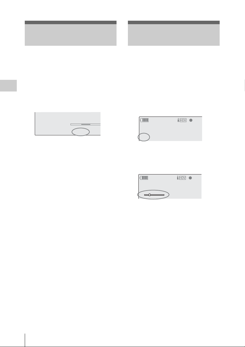
Adjusting the Iris
TLCS
.
M
F
∗
ATW 4300K
PPOFF
++
T1.6
18dB
1 1.5 2 3 4 5 7 10
Adjusting the Zoom
Adjust the iris opening using the iris ring of the
lens according to the brightness of the subject.
For operations of the lens, refer to the operation
guide of the lens.
For lens which supports the iris position
indication, the current setting is displayed on the
Recording
screen when you press the DISPLAY/BATT
INFO button.
When the “TLCS” (total level control) setting of
the CAMERA SET menu has been changed, the
current setting is indicated with a symbol before
the iris value.
++: Approx. one stop further open
+: Approx. half a stop further open
No symbol: Standard
–
: Approx. half a stop further closed
– –
: Approx. one stop further closed
For details on TLCS, see “TLCS” (page 105) in
“Setup Menu List.”
When using a zoom lens, rotate the zoom ring of
the lens to adjust the zoom.
For operations of the lens, refer to the operation
guide of the lens.
For a lens which supports the zoom position
indication, the current zoom position is displayed
on the screen in the range of 0 (Wide) to 99 (Tele)
when you press the DISPLAY/BATT INFO
button.
120min
A: 60min
B: 120min
Z99
The numerical indication can be changed to that
in a bar by changing the “Zoom Position” setting
of “Display On/Off” (page 111) of the LCD/VF
SET menu.
120min
A: 60min
B: 120min
W T
STBY
STBY
S&Q
S&Q
48
Adjusting the Iris / Adjusting the Zoom
Page 49

Adjusting the Focus
W
Rotate the focus ring of the lens for the best focus
while observing the picture on the LCD monitor/
viewfinder screen.
For operations of the lens, refer to the operation
guide of the lens.
The emphasis level and color of the contours can
be set with “Peaking” (page 110) of the LCD/VF
SET menu.
Expanded Focus
When you press the EXPANDED FOCUS
button, the center area of the picture is magnified
on the LCD monitor/viewfinder screen, making
the focus adjustment easier.
Press the EXPANDED FOCUS button again or
leave the focus ring unmoved for 5 seconds to
resume the normal angle for recording.
EXPANDED FOCUS button
REC REVIEW
EXPANDED
FOCUS
D
W
F
F
E
S
U
A
P
/
Y
A
L
P
E
ZEBRA PEAKING
CE
B
A
PRST
PEAKING button
Recording
Peaking
When you press the PEAKING button, the
peaking function is activated. This function
emphasizes the contours of the images on the
LCD monitor/viewfinder screen, making manual
focusing easier.
This function does not affect recording signals.
Adjusting the Focus
49
Page 50

Reducing Flickers
To reduce flickers, try either of the following two
methods:
Setting the shutter speed according to
the power-supply frequency
Activate the electronic shutter (page 46) and set
Recording
the shutter speed according to the power supply
frequency.
When the frequency is 50 Hz
Set the shutter speed to
When the frequency is 60 Hz
Set the shutter speed to
Using the Flicker-Reduction function
Set “Mode” of “Flicker Reduce” (page 104) of
the CAMERA SET menu to “Auto” or “On” and
set “Frequency” to the power-supply frequency
(50 Hz or 60 Hz).
Note
If the frame rate selected for recording is close to
the power-supply frequency, flicker may not be
reduced sufficiently even if you activate the
Flicker-Reduction function. In such cases, use the
electronic shutter.
Recommended settings for flicker reduction
Frequency
Always set “Frequency” to the power-supply
frequency value appropriate for the shooting area.
Mode
• It is recommended to set “Mode” to “Off” when
shooting outdoors or under lighting that does
not cause flicker. (It can be also “Auto,” but the
compensation may not be done properly.)
• It is recommended to set “Mode” to “Auto”
when shooting indoo rs or under various lighting
that may cause flicker, such as fluorescent,
sodium, or mercury-vapor lamps. (If
continuously shooting under lighting that may
cause flicker, “Mode” should be set to “On.”)
1
/50 or 1/
1
/60 or 1/
100
120
seconds.
seconds.
The recommended “Mode” settings are shown
below.
Flicker
Reduce/
Mode
Auto Recommended Acceptable
On Acceptable Not recommended
Off Not recommended Recommended
Note
The flicker-reduction function does not operate
when signals are being fed from the HD SDI A/B
(Dual-Link) connectors.
Under lighting
that may cause
flicker
Environments
Under lighting
that does not
cause flicker
Reducing Flickers
50
Page 51

Setting the Time Data
mode selected with the TC/UB SET menu is
restored.
Setting the Timecode
Time data, such as the timecodes, user bits, and
the clock time, are recorded with pictures.
Running Modes of the Timecode
For the timecode, three running modes and Clock
mode can be selected.
Rec Run mode
The timecode advances during recording only.
The continuity of the timecode is maintained
between clips in the sequence of recording as long
as the SxS memory card is not changed.
If you remove the memory card and record on
another card, the timecode will not continue when
you return the first card to the slot again.
Free Run mode
The timecode keeps advancing regardless of
recording.
Regen mode
The timecode advances during recording only.
When you insert another memory card, the
camcorder starts next recording so that the
timecode continues to the last recorded timecode
on the card.
Clock mode
The current clock time is recorded for the
timecode.
Notes
• In Interval Recording, Frame Recording, Slow
& Quick Motion Recording, the timecode
advances in Rec Run mode regardless of the
“Run” setting if you set “Mode” of “Timecode”
to “Preset” with the TC/UB SET menu. If you
set it to “Clock,” the timecode advances in
Regen mode.
• When the Picture Cache function is active
(P.Cache Rec Se tting: On), the t imecode always
advances in Free Run mode. When the Picture
Cache Rec function is deactivated, the running
Specify the timecode to be recorded with
“Timecode” and “TC Format” of the TC/UB SET
menu.
For details on menu operations, see “Basic Menu
Operations” on page 100.
TC/ UB
SET
sers Bit
B
B
M
ode
: Preset
Run :
Setting:
R
eset
Rec Run
00:00:00:00
Timecode
U
TC Format: DF
00:00
Setting the timecode to a desired value
1 Set “Mode” of “Timecode” to “Preset.”
2 Specify the timecode value on the
Setting line and select “SET.”
Resetting the timecode
You can reset the timecode to be recorded in
running modes to “00:00:00:00.”
1 Select “Reset” of “Timecode.”
2 Select “Execute.”
Using the actual time as the timecode
Set “Mode” of “Time Code” to “Clock.”
The time of the built-in clock is recorded as the
timecode.
Switching between DF and NDF of the
timecode
Using “TC Format” of the TC/UB SET menu, DF
(drop-frame mode) and NDF (non-drop frame
mode) of the timecode can be switched.
Note, however, that the mode is fixed either to DF
or NDF regardless of the TC Format setting,
depending on the current frame-rate setting.
Recording
Setting the Time Data
51
Page 52

Restrictions on the timecode
The timecode setting is restricted by the current
video format.
Video formats Frame
setting
HQ 1920/59.94i
HQ 1920/29.97P
HQ 1440/59.94i
HQ 1440/29.97P
SP 1440/59.94i
DVCAM59.94i SQ
DVCAM59.94i EC
Recording
DVCAM29.97P SQ
DVCAM29.97P EC
HQ 1920/50i
HQ 1920/25P
HQ 1440/50i
HQ 1440/25P
SP 1440/50i
DVCAM50i SQ
DVCAM50i EC
DVCAM25P SQ
DVCAM25P EC
HQ 1920/23.98P
HQ 1440/23.98P
HQ 1280/23.98P
SP 1440/23.98P
HQ 1280/59.94P 00 to 29
HQ 1280/50P 00 to 24
HQ 1280/29.97P 00 to 29 DF/NDF switchable
HQ 1280/25P 00 to 24 Fixed to NDF
00 to 29 DF/NDF switchable
00 to 24 Fixed to NDF
00 to 23
00 to 29
(double
count)
(double
count)
1)The frame digits in “Setting” is limited to 00, 04, 08,
12, 16, and 20.
The frame at the beginning of recording is limited to
00, 04, 08, 12, 16, or 20.
As the SDI OUT connector output becomes 60i
because of the 2-3 pull-down process except when
“23.98P Output” (page 109) is set to “23.98PsF” for
1920/23.98P in E-E Display/Recording mode, the
frame digits of the timecode added to the SDI OUT
connector output are changed to values in the range of
00 to 29.
2)Even in Clock mode, the timecode is gradually
shifted, because it is counted by NDF.
As any output becomes 2-3 pulled-down video except
those from the SDI OUT and HDMI OUT connectors
with “23.98P Output” (page 109) set to “23.98PsF”
TC Format
(Fixed to DF in
Clock mode)
1)
Fixed to NDF
3)
DF/NDF switchable
(Fixed to DF in
Clock mode)
DF/NDF switchable
(Fixed to DF in
Clock mode)
Fixed to NDF
(Fixed to DF in
Clock mode)
for 1920/23.98P in, there may be a field that has dual
timecodes on the display.
3)With DF, the frame digits can be set as desired in the
range of 00 to 29.
With NDF, the frame at the beginning of recording is
limited to 00, 05, 10, 15, 20, or 25.
Setting the User Bits
You can add a hexadecimal number of 8 digits for
pictures as the user bits.
The user bits can also be set to the current date.
Use “Users Bit” of the TC/UB SET menu.
TC/UB
SET
B
Timecode
B
U
sers Bit
TC Format: DF
00:00
M
ode
: Fix
Setting:
20 07 12 08
Setting eight digits as desired
2)
1 Set “Mode” of “Users Bit” to “Fix.”
2 Specify the values on the Setting line
and select “SET.”
You can set hexadecimal digits A to F with
the corresponding alphabetics.
Recording the current date as the user
bits
Set “Mode” of “Users Bit” to “Date.”
The current date is displayed on the Setting line.
Displaying the Time Data
In E-E Display/Recording mode, pressing the
DISPLAY/BATT INFO button displays the time
data on the screen.
REC
The indication is switched among the timecode,
user bits, and recording duration each time you
press the TC/U-BIT/DURATION button.
TCG 00:00:00:00
Q
1920/59.94i
H
Q M
otion
S&
Setting the Time Data
52
Page 53

Display Contents
TCG **:**:**:** Tmecode
CLK **:**:**:** Timecode (Clock mode)
UBG ** ** ** ** User bits
DUR **:**:** Duration from the beginning of
recording
Recording Audio Signals
Two channels (CH-1/CH-2) of audio can be
recorded (Linear PCM recording) in
synchronization with video recording.
Connect the supplied microphone or an external
audio source.
For details, see “Attaching the Microphone” on
page 29.
AUDIO
CH-1 CH-2
LEVEL
AUDIO
CH-1 CH-2
SELECT
AUTO
MANUAL
AUDIO LEVEL controls
AUDIO SELECT
switches
Recording
Adjusting the Audio Recording Levels
You can select automatic or manual adjustment
mode independently for each channel.
To adjust the levels automatically (AGC)
When the AUDIO SELECT switches CH-1 and
CH-2 are set to AUTO, the audio recording levels
are automatically adjusted.
Two AGC modes can be selected with “MIC
AGC” of “Audio Input” (page 106) of the
AUDIO SET menu.
High: For general audio recording
Recording Audio Signals
53
Page 54

Low: For music recording or recording in an
gg
event where high sound pressure may be
generated
To adjust the levels manually
Set the AUDIO SELECT switches CH-1 and CH2 to MANUAL and adjust the audio recording
levels by turning the AUDIO LEVEL controls.
Set the controls to 5 for the reference setting (0
dB). Setting to 10 maximizes the level (+12 dB),
and setting to 0 minimizes it (–
Recording
The input levels are displayed on the screen when
you press the DISPLAY/BATT INFO button.
∞).
Monitoring the Audio
You can monitor the sounds being recorded with
the headphones connected to the headphone
connector (stereo mini jack).
Headphone connector
5 7 10 15 20 30 oo
18dB
SHT
:1/2000
m
CH1
CH2
Fine adjustment of the recording is possible using
“TRIM CH-1” and “TRIM CH-2” of “Audio
Input” (page 106) of the AUDIO SET menu, For
high-quality recording, adjust not only the
AUDIO LEVEL controls but also “TRIM CH-1”
and “TRIM CH-2” so that the optimum
microphone sensitivity is obtained. When you
perform fine adjustments with “TRIM CH-1” and
“TRIM CH-2,” set the AUDIO LEVEL controls
to 5 and adjust the items so that the appropriate
meter indications are obtained.
If the maximum sound pressure cannot be
estimated or sudden sound pressure is expected,
set “Limiter” of “Audio Input” (page 106) of the
AUDIO SET menu to “On.”
Notes
• When you manually adjust the recording levels,
check that no distortion is generated, by
monitoring through headphones, etc.
• If the AUDIO LEVEL controls are set to a value
less than 5, the recording levels will not reach
the full scale.
Audio recording in special recording
modes
• No audio recording is made in Interval
Recording or Frame Recording.
• No audio recording is made in Slow & Quick
recording if the recording frame rate is set to a
value different from the playback frame rate.
MONITOR
VOLUME
MONITOR VOLUME buttons
Note
The built-in speaker is disabled in E-E Display/
Recording mode.
To adjust the audio monitoring volume
Use the MONITOR VOLUME buttons.
Pressing the + button increases the volume, and
pressing the – button decreases it. To muffle the
sound, set it to the minimum level.
While you adjust the volume, the level is
displayed as a bar on the screen.
Recording Audio Signals
54
Page 55

Outputting the Color Bars and Reference Tone
The camcorder can output a color-bar signal in
place of the camera picture.
A 1-kHz reference tone is output with the color
bar signal if “1kHz Tone” of “Audio Input” (page
106) is set to “On” with the AUDIO SET menu.
The color-bar and reference-tone signals are fed
out from the HD SDI (A/B), SDI OUT, HDMI
OUT, and i.LINK (HDV/DV) connectors. The
VIDEO OUT connector outputs the color-bar
signal only.
BARS/CAM button
Notes
• When recording of the camera image is in
progress, it cannot be switched to the color-bar
picture even if you press the BARS/CAM
button. (You can switch the color-bar picture to
the camera picture.)
• The color bar mode cannot be selected in Slow
& Quick Motion mode.
Recording
BARS/CAM F REV
THUMBNAIL
PLAY/PAUSE
F FWD
j
G
/SJ
PREV STOP NEXT
lsL
Press the BARS/CAM button.
The camera picture is switched to color bars.
To return to the camera picture, press the button
again.
You can select the type of color bars with “Color
Bar Type” (page 103) of the CAMERA SET
menu.
Multi: ARIB multiformat color bars
75%: Vertical stripes of 75% luminance
100%: Vertical stripes of 100% luminance
Outputting the Color Bars and Reference Tone
55
Page 56
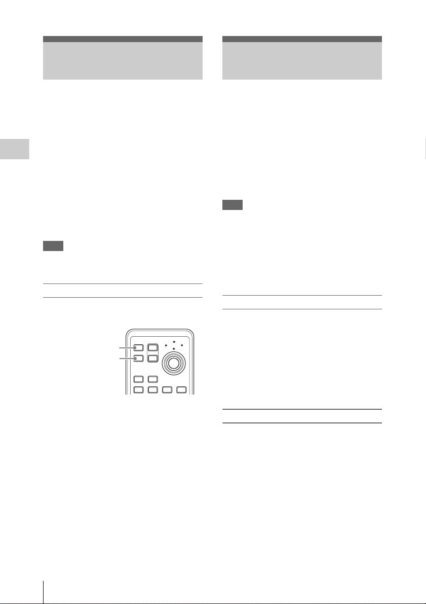
Recording Shot Marks
Adding the OK Mark
When you record shot marks for important scenes
of a clip recorded in HD mode as subsidiary data,
you can access the marked points easily on a Shot
Mark screen, which only displays scenes with
shot marks only. This increases editing
efficiency.
For the Shot Mark screen, see “Display ing the SHOT
Recording
MARK Screen (HD Mode Only)” on page 91.
The camcorder permits yo u to record two types of
shot marks: shot mark 1 and shot mark 2.
Shot marks can be recorded as needed during
recording or can be added after recording while
checking the playback pictures.
Note
Shot marks cannot be recorded for clips recorded
in SD mode.
Inserting a shot mark during recording
Activate the IR Remote Commander (page 30),
and use the SHOTMARK 1 or 2 button.
SHOTMARK 1 button
SHOTMARK 2 button
Press the SHOTMARK 1 or 2 button where
you wish to insert a mark.
If the Shot Mark1 or Shot Mark2 function is
assigned to an assignable button, you can also use
it instead (page 58).
12T
ZOOM
SHOTMARK
W
SUB CLIP
THUMBNAIL
PREV NEXT
PLAY/PAUSE
.>xu
PUSH SET
By adding the OK mark to a clip recorded in HD
mode, you can preve nt the clip from being deleted
or divided inadvertently.
The OK mark is also used to obtain a thumbnail
screen of only the marked clips (OK-Clip
thumbnail screen) when you press the
THUMBNAIL button.
For the OK-Clip thumbnail screen, see “Displaying
the OK-Clip thumbnail screen (HD mode)” on page
81.
Note
The OK mark cannot be added to clips recorded
in SD mode.
To add the OK mark in E-E Display mode, assign
the OK Mark function to an assignable button.
For function assignment, see “Changing Functions
of the Assignable Buttons” on page 58.
Adding the OK mark
In E-E Display mode, you can add the OK mark
to the last clip recorded on the SxS memory card
currently selected.
When recording of a clip ends, press the
assignable button to which you assigned the
OK Mark function.
STOP
The message “OK Mark” is displayed on the
screen for three seconds.
Deleting the OK mark
In E-E Display mode, you can delete the OK mark
added to the last clip on the SxS memory card
currently selected.
A shot mark of the type corresponding to the
button you press is recorded.
For operations to add shot marks after recording,
see “Adding Shot Marks During Playback (HD
Mode)” on page 84 and “Adding/Deleting Shot
Marks (HD Mode Only)” on page 92.
Recording Shot Marks / Adding the OK Mark
56
1 Press the assignable button to which
you assigned the OK Mark function.
The confirmation message “Execute/Cancel”
is displayed.
2 Select “Execute.”
The OK mark of the last clip is deleted.
Page 57

To add or delete the OK mark to or from clips
REC REVIEW
before the last one
Use the Clip Operation menu on the thumbnail
screen.
See “Adding/Deleting the OK Mark to/from a Clip
(HD Mode Only)” on page 88.
Rec Review
You can review the last recorded clip on the
screen (Rec Review).
D
W
F
F
E
S
U
A
P
/
Y
A
L
P
EXPANDED
FOCUS
REC REVIEW
button
Press the REC REVIEW button after
recording is finished.
You can assign the Rec Review function to an
assignable button to use it instead (page 58).
Recording
Playback of the specified block of the clip begins.
In Rec Review, the last 3 seconds, 10 seconds, or
the entire part of the clip is displayed, depending
on the Rec Review setting (page 105) of the
CAMERA SET menu. It is set to 3 seconds at the
factory.
Rec Review is terminated at the end of the clip,
resuming STBY (recording standby) status.
To interrupt Rec Review
Press the REC REVIEW or STOP button or the
assignable button to which you assigned the Rec
Review function.
Rec Review is canceled, resuming STBY
(recording standby) status.
Notes
• If the duration of the last recorded clip is less
than the time (3 or 10 seconds) specified for Rec
Review, the clip is played back from the
beginning to the end.
Rec Review
57
Page 58
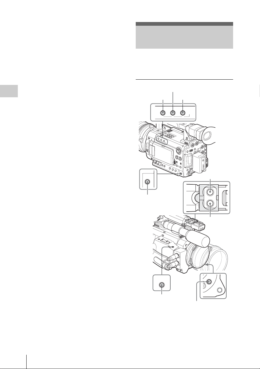
If the clip was recorded in SD mode and
segmented into multiple files because the file
size exceeded 2GB, only the last file is played.
• During Rec Review playback, the playback
control buttons other than the STOP button are
disabled.
• If the video for mat was changed after recording,
Rec Review cannot be performed (except when
the change was from SP 1440/23.98P to SP
1440/59.94i).
• The Setup and P.PROFILE menus cannot be
operated during Rec Review.
Recording
Changing Functions of the Assignable Buttons
The camcorder has four assignable buttons to
which you can assign various functions for
convenience.
ASSIGN 2 button
ASSIGN 1 button
LENS INFO
ASSIGN 3 button
BRT DISP HISTOGRAM
123
ASSIGN
ASSIGN 5
ASSIGN 5 button
ASSIGN 6 button
ASSIGN 6 ASSIGN 7
START/STOP
REC
ASSIGN 7 button
D
W
F
F
E
S
U
A
P
/
Y
A
L
P
ASSIGN 8
ASSIGN 4
AUTO
WHT BAL
ASSIGN 8 button
ASSIGN 4 button
The following functions are assigned at the
factory:
ASSIGN 1 button (LENS INFO)
Depth-of-field indication on/off
Changing Functions of the Assignable Buttons
58
Page 59

ASSIGN 2 button (BRT DISP)
Brightness-level indication on/off
ASSIGN 3 button (HISTOGRAM)
Histogram indication on/off
ASSIGN 4 and ASSIGN 5 buttons
Recording start/stop
ASSIGN 6, ASSIGN 7, and ASSIGN 8 buttons
No function is assigned (Off).
Changing Functions
Use “Assign Button” of the OTHERS menu.
For details on menu operations, see “Basic Menu
Operations” on page 100.
1 Select “Assign Button” from the
OTHERS menu.
O
THE
RS
All
Reset
Cam
era Data
Ti
me
Clock
00:00
Lan guage
Ass i gn But ton
Tally
Zone
Set
:
:
B
UTC +09:00
B
English
B
B
<1> : Lens Info
<2> : BRT D
<3> : H
<4> : R
<5> : O
<6> : O
isp
istogram
ec
ff
ff
2 Select the button to which you wish to
assign a function.
Function Contents
BRT Disp Brightness level indication on/off
Histogram Histogram indication on/off
Lens Info Depth-of-Field indication on/off
1)
OK Mark
OK Mark add/delete
1)Valid in HD mode only
4 Exit the menu.
The assigned functions can be viewed on the
BUTTON/REMOTE status screen (page 98).
Recording
3 Select the function to be assigned.
Function Contents
Marker All marker indications (safety-
Last Clip DEL Last clip delete
ATW ATW function on/off
ATW Hold ATW Hold function on/off
Rec Review Rec Review start/stop
Rec Recording start/stop
Picture Cache Picture Cache mode on/off
Freeze Mix Freeze Mix start/stop
Expanded
Focus
Spotlight TLCS Spotlight mode on/off
Backlight TLCS Backlight mode on/off
IR Remote IR Remote Commander enable/
Shot Mark1
Shot Mark2
VF Mode Viewfinder screen mode (color/
zone marker, center marker,
aspect marker, guide frames) on/
off
Expanded Focus function on/off
disable
1)
Shot mark 1 insert
1)
Shot mark 2 insert
monochrome) switching
Changing Functions of the Assignable Buttons
59
Page 60

Interval Recording
The Interval Recording (time-lapse recording)
function is especially effective for shooting
objects that move very slowly.
The specified number of frames are automatically
recorded at the specified intervals.
Preparatory Settings
Before starting Interval Recording, make the
necessary settings on the CAMERA SET menu in
advance.
For details on menu operations, see “Basic Menu
Operations” on page 100.
1 Select “Interval Rec” of the CAMERA
SET menu.
Recording
Recording interval (Interval Time)
Number of frames for one recording session
(Number of Frames)
It is recommended to fix the camcorder to a tripod
or equivalent and use the IR Remote Commander
to start/stop recording rather than the camcorder.
Notes
• Interval Recording cannot be set to “On”
simultaneously with Frame Recording, Picture
Cache Recording, or Slow & Quick Motion.
When you set Interval Recording to “On,”
Frame Recording, Picture Cache Recording and
Slow & Quick Motion are forcibly set to “Off.”
• No audio recording is executed in Interval
Recording.
• Interval Recording cannot be made if a setting
which includes “HDV” or “DVCAM” is
selected with “SDI/HDMI/i.LINK I/O Select”
of the VIDEO SET menu.
• Interval Recording cannot be performed if
“Format” of “System” of the OTHERS menu is
set to “SP 1440/23.98P.”
C
AMERA SET
Gain Setup
Shutter
Slow S
Color
00:00
Flicker
Interval
Fra
Bar T
me
hutter
Reduce
Rec
Rec
ype
B
B
B
:
:
B
B
Multi
O
ff
Set t in g
Interval Tim
Number of Frames
e
Off
:
: 1sec
: 1
2 Set “Setting” to “On.”
The camcorder enters Interval Recording
mode.
When the special recording mode indication
on the screen is active, “Interval Rec” flashes
on the screen.
3 Set the time between recordings with
“Interval Time.”
You can select the time from among 1 to10/
15/20/30/40/50 seconds, 1 to 10/15/20/30/
40/50 minutes, and 1 to 4/6/12/24 hours by
scrolling the display.
4 Set the number of frames to be recorded
at a time with “Number of Frames.”
When the video format (page 37) is set to
“HQ 1280/59.94P” or “HQ 1280/50P,” you
can select from among 2, 6, and 12 frames.
With other settings, you can select from
among 1, 3, 6, and 9 frames.
5 Exit the menu.
Performing Interval Recording
Interval Recording
60
When the preparatory settings are completed, you
can start recording.
Press the REC START/STOP button on the
handle or the grip.
Interval Recording begins.
Page 61

The flashing “Interval Rec” on the screen is now
steadily lit.
Notes
• You cannot change the “Interval Time” and
“Number of Frames” settings while Interval
Recording is in progress. To change them,
pause recording.
• After starting Interval Recording, Rec Review
operation is disabled, even during an interval.
• The timecode is recorded in Rec Run mode
(page 51) during Interval Recording.
• Some extra frames may be recorded if you stop
recording or switch the card slot while
recording is halted in Interval Recording mode.
Stopping Interval Recording
Press the REC START/STOP button on the
handle or the grip.
Interval Recording stops.
To restart Interval Recording, press the button
again.
Canceling Interval Recording mode
Set “Setting” of “Interval Rec” of the CAMERA
SET menu to “Off.”
Note
It automatically returns to “Off” when you set the
power switch to OFF, while the “Interval Time”
and “Number of Frames” settings are maintained.
Frame Recording
The Frame Recording function is especially
effective for clay animation recording.
The specified number of frames are recorded
intermittently when you press a recording start
button.
It is recommended to fix the camcorder to a tripod
or equivalent and use the IR Remote Commander
to start/stop recording rather than pressing a
recording start button of the camcorder.
Notes
• Frame Recording cannot be set to “On”
simultaneously with Interval Recording, Picture
Cache Recording or Slow & Quick Motion.
When you set Frame Recording to “On,”
Interval Recording, Picture Cache Recording
and Slow & Quick Motion are forcibly set to
“Off.”
• No audio recording is executed in Frame
Recording.
• Frame Recording cannot be made if a setting
which includes “HDV” or “DVCAM” is
selected with “SDI/HDMI/i.LINK I/O Select”
of the VIDEO SET menu.
• Frame Recording cannot be performed if
“Format” of “System” of the OTHERS menu is
set to “SP 1440/23.98P.”
Recording
Preparatory Settings
Before starting Frame Recording, make the
necessary settings on the CAMERA SET menu in
advance.
For details on menu operations, see “Basic Menu
Operations” on page 100.
1 Select “Frame Rec” of the CAMERA
SET menu.
C
00:00
Shutter
Slow S
Color
Flicker
Interval
Fra
P.
AMERA SET
Bar T
me
C
ache Rec
hutter
Reduce
Rec
Rec
ype
B
B
:
Multi
:
O
B
B
B
ff
Setting
Num
Frame Recording
ber of Frames
:
: 1
O
n
Off
O
ff
61
Page 62

2 Set “Setting” to “On.”
The camcorder enters Frame Recording
mode.
When the special recording mode indication
on the screen is active, “Frame Rec” flashes
on the screen.
3 Select the “Number of Frames” value
for one recording session.
You can select from among 2, 6, and 12 when
the video format (page 39) is set to 720/
59.94P or 720/50P.
Recording
With other video formats, you can select
from among 1, 3, 6, and 9.
4 Exit the menu.
Performing Frame Recording
When the preparatory settings are completed, you
can start recording.
1 Press the REC START/STOP button on
the handle or the grip.
Recording in Frame Rec mode begins.
The “Frame Rec” indication stops flashing.
When the number of frames you specified
with the menu are recorded, the camcorder
automatically enters FRM STBY (Frame Rec
Standby) status.
• Some extra frames may be recorded if you stop
recording or switch the card slot while
recording is paused in Frame Rec mode.
Stopping Frame Recording
Set “Setting” of “Frame Rec” of the
CAMERA SET menu to “Off.”
Recording stops and Frame Rec mode is
canceled.
Note
It automatically returns to “Off” when you set the
power switch to OFF, while the “Number of
Frames” setting is maintained.
2 Press the REC START/STOP button
again.
Each time you press the REC START/STOP
button, the camcorder records the specified
number of frames then enters FRM STBY
status.
Notes
• Recording cannot be stopped until the specified
number of frames are recorded. If the power
switch is set to OFF during recording, the power
is only shut off after the specified number of
frames are recorded.
• The Rec Review function cannot be used while
recording in Frame Rec mode is in progress.
• You cannot change the “Number of Frames”
setting while recording in Frame Rec mode is in
progress. To change it, pause the recording.
• The timecode is recorded in Rec Run mode
(page 51) during Frame Recording.
Frame Recording
62
Page 63

Picture Cache Recording
The Picture Cache Recording is enabled and
the CACHE REC lamp lights.
CACHE REC lamp
When the Picture Cache function is active, the
camcorder stores the last few seconds of video
captured in the built-in cache memory to permit
you to start recording video on an SxS memory
card from a point before you start recording.
The maximum picture cache time is 15 seconds.
Notes
• Picture Cache Recording cannot be set to “On”
simultaneously with Frame Recording, Interval
Recording, or Slow & Quick Motion. When you
set Picture Cache Recording to “On,” Frame
Recording, Interval Recording and Slow &
Quick Motion are forcibly set to “Off.”
• The following operations set Picture Cache
Recording to “Off.”
—Setting Interval Recording to “On”
—Setting Frame Recording to “On”
—Setting Slow & Quick Motion to “On”
—Changing the recording format
• When Picture Cache Recording is “On,” the
time code is recorded in Clock mode when it is
selected with the TC/UB SET menu (page 51)
or in Free Run mode in other conditions.
Preparatory Settings
Before starting Picture Cache Recording, make
the necessary settings on the CAMERA SET
menu in advance.
For details on menu operations, see “Basic Menu
Operations” on page 100.
1 Select “P.Cache Rec” of the CAMERA
SET menu.
C
00:00
S
Color
Flicker
Inter val
Fra
P.
S&Q M
AMERA SET
low Shutter
Bar T
me
C
ache Rec
Reduce
Rec
otion
Rec
ype
B
:
:
B
B
B
B
Multi
O
ff
Setting
Rec T i me
: O
ff
: 13-15sec
2 Set “Setting” to “On.”
CACHE
REC
The Setting On/Off operation can be
alternatively made by using an assignable
button if you assign the Picture Cache
function to the button.
For function assignment, see “Changing
Functions of the Assignable Buttons” on page
58.
3 Set the time to cache video with “Rec
Time.”
You can select the time from among 0-2 sec,
2-4 sec, 4-6 sec, 6-8 sec, 8-10 sec, and 13-15
sec.
(The actual time to trace back to start
recording may vary within the selected time
range depending on conditions.)
4 Exit the menu.
The special recording/operation status indication
block on the screen shows “
green).
Performing Picture Cache Recording
Starting Picture Cache Recording
Check that the CACHE REC lamp is lit and
press the REC START/STOP button on the
handle or the grip.
zCACHE.” (z in
Recording
Picture Cache Recording
63
Page 64

Recording begins, and stored video in the cache
memory is written first to the SxS memory card.
The on-screen “
the color of
zCACHE” indication changes
z to red.
Slow & Quick Motion Recording
Stopping Picture Cache Recording
Press the REC START/STOP button on the
handle or the grip.
Canceling Picture Cache function
Set “Setting” of “P.Cache Rec” of the CAMERA
SET menu to “Off” or press the assignable button
Recording
to which you assigned the Picture Cache function.
Notes
• If you change the recording format, the cached
data are cleared and caching is newly started.
Therefore, data cached before you changed the
format cannot be recorded if you start Picture
Cache Recording immediately after changing
the format.
• If you start/stop Picture Cache Recording
immediately after you insert an SxS memory
card, data may not be recorded on the card.
• Picture caching starts when you activate the
Picture Cache function. Therefore, video before
the function is activated cannot be recorded
with Picture Cache Recording.
• Picture Cache Recording is invalid for external
input signal (HDV).
• As picture caching is disabled while an SxS
memory card is being accessed, such as during
playback, Rec Review, or thumbnail screen
display, Picture Cache Recording of such a
period cannot be made.
• Although you can change the “Rec Time”
setting on the menu even while recording is in
progress, any new value becomes valid in such
a case only after recording is stopped.
When the camcorder is in HD mode and one of
the following video formats is selected (page 37),
you can set a frame rate for recording different
from that for playback:
NTSC Area/NTSC (J) Area
HQ 1920/29.97P, HQ 1920/23.98P, HQ 1280/
59.94P, HQ 1280/29.97P, HQ 1280/23.98P
PAL Area
HQ 1920/25P, HQ 1280/50P, HQ 1280/25P
By recording at a different frame rate, you can
obtain a smoother slow-motion or quick-motion
effect than with slow-speed or fast-speed
playback of a material recorded at the normal
recording speed.
Example
When the video format is HQ 1280/23.98P,
recording with a frame rate between 1 and 23 fps
provides a quick-motion effect in playback, and
recording with a frame rate between 25 and 60 fps
provides a slow-motion effect in playback.
Notes
• Slow & Quick Motion recording cannot be
activated in SD mode.
• Slow & Quick Motion recording cannot be
made if a setting which includes “HDV” or
“DVCAM” is selected with “SDI/HDMI/
i.LINK I/O Select” of the VIDEO SET menu.
• When you set Slow & Quick Motion to “On,”
Frame Recording, Interval Recording, and
Picture Cache Recording are forcibly set to
“Off.” However, Slow & Quick Motion cannot
be activated while Frame Recording, Interval
Recording, or Picture Cache Recording is in
progress.
• No audio recording is made if the recording
frame rate is set to a value different from the
playback frame rate.
• The timecode is recorded in Rec Run mode
(page 51) during Slow & Quick Motion
recording.
Slow & Quick Motion Recording
64
Page 65

Preparatory Settings
Before starting Slow & Quick Motion recording,
make the necessary settings with the CAMERA
SET menu in advance.
For details on menu operations, see “Basic Menu
Operations” on page 100.
1 Select “S&Q Motion” from the
CAMERA SET menu.
C
AMERA SET
Color Bar Type
Flicker
Inter val
me
Fra
00:00
P.
C
ache Rec
S&Q M
Review
Rec
Rec
otion
Reduce
Rec
:
:
B
B
B
B
B
Multi
O
ff
On
Format
S&Q Ratio
HQ1280/23.98
:
: 60
2 Select the video format for Slow &
Quick Motion recording with “On
Format.”
3 Select the frame rate for recording with
“S&Q Ratio.”
The setting range varies depending on the
current video format.
With a format of 1920 horizontal
resolution: 1 to 30 fps
With a format of 1280 horizontal
resolution: 1 to 60 fps
CACHE
REC
S&Q
P
S&Q dial
In Slow & Quick Moti on mode, the frame rate can
be varied by rotating the S&Q dial.
When the special recording mode indication on
the screen is active, “S&Q Motion” is displayed
on the screen and [Recording frame rate]/
[Playback frame rate] fps is displayed under
“S&Q Motion.”
REC
TCG 00:00:00:00
Q
1920/23.98P
H
Q M
S&
29/24fps
Recording
otion
4 Exit the menu.
5 Press the S&Q dial.
A confirmation message is displayed.
6 Operating the jog dial, select “Execute.”
The camcorder enters Slow & Quick Motion
mode and the indicator lights.
Recording in Slow & Quick Motion Mode
Starting recording
When the preparatory settings are completed, you
can start recording.
Press the REC START/STOP button on the
handle or the grip.
Slow & Quick Motion recording begins.
Notes
• You cannot change the “On Format” and “S&Q
Ratio” settings while Slow & Quick Motion
recording is in progress. To change them, pause
the recording.
• The timecode is recorded in Rec Run mode
during Slow & Quick Motion recording (page
51).
Slow & Quick Motion Recording
65
Page 66

Stopping recording
Press the REC START/STOP button on the
handle or the grip.
Slow & Quick Motion recording stops.
Note
When recording at a low-speed frame rate, it may
take time until recording stops after you press the
REC START/STOP button.
Canceling Slow & Quick Motion mode
Recording
Press the S&Q dial.
Note
Slow & Quick Motion mode is automatically
canceled when you set the power switch to OFF,
while the “On Format” and “S&Q Ratio” settings
are maintained.
Freeze Mix: Image Alignment
Using the Freeze Mix function, an image (still
picture) of a clip recorded in HD mode can be
temporarily superimposed on the current camera
picture, permitting you to easily align images for
next recording.
To use the Freeze Mix function
Assign the Freeze Mix function to one of the
assignable buttons.
For details, see “Changing Functions of the
Assignable Buttons” on page 58.
Superimposing a Freeze Mix image
1 Stop recording to set the camcorder to
STBY (recording standby) status.
2 Press the REC REVIEW button to
review the record ed images, or press the
ASSIGN button to which you assigned
“Freeze Mix.”
3 Press the ASSIGN button to which you
assigned “Freeze Mix” at the image
with which you want align.
Freeze Mix: Image Alignment
66
The image where y ou pressed the ASSIGN button
3 is displayed as a still picture over the
in step
current camera picture.
Canceling Freeze Mix status
You can cancel it with the ASSIGN button to
which you assigned “Freeze Mix” or the REC
START/STOP button on the handle or the grip.
• When you cancel Freeze Mix status by pressing
the ASSIGN button, the normal camera picture
is restored.
• When you cancel Freeze Mix status by pressing
the REC START/STOP button on the handle or
the grip, normal recording begins.
Notes
• The Freeze Mix function cannot be used in SD
mode.
Page 67

• The Freeze Mix function cannot be used if the
recording video format is SP 1440/23.98P.
• If the recorded picture and the current camera
picture differ in video format, the Freeze Mix
display cannot be achieved.
• The Freeze Mix display cannot be obtained in
Slow & Quick Motion mode or Slow Shutter
mode.
• You cannot operate the Setup menus and
P.PROFILE menu in Freeze Mix status.
Picture Profiles
You can customize the picture quality, depending
on the conditions or circumstances of recording,
and store them as a picture profile, enabling the
picture quality to be resumed just by your
selecting the picture profile.
Ten different picture profiles (PP1 to PP10) can
be stored in memory.
The same standard (reference) values are
registered to six picture profiles at the factory as
those specified for the Picture Profile Off status.
The P.PROFILE menu is available for pictureprofile operations.
Note
The picture profiles can be operated only in E-E
Display mode.
When an external remote control device, such as
the RM-B750/B150 Remote Control Unit, is
connected, PP10 is automatically selected, and
the picture profiles can be adjusted from the
control device.
For details, refer to the Supplement in the supplied
CD-ROM labeled “Manuals for Solid-State Memory
Camcorder.”
Recording
Registering the Customized Settings as a Picture Profile
PICTURE PROFILE button
SEL/SET CANCEL
PICTURE PROFILE
B
Picture Profiles
67
Page 68

1 Press the PICTURE PROFILE button.
The P.PROFILE menu is displayed.
2 Operating the jog dial, select “SEL”
from the P. PROFILE menu then select
the picture profile number (PP1 to
PP10) to operate.
P.PROFILE
OFF
SEL
SET
Recording
STANDARD
PP1:
PP2:
STANDARD
PP3:
STANDARD
PP4:
STANDARD
PP5:
STANDARD
PP6:
STANDARD
Example:
P.PROFILE
OFF
SEL
PP1:
PP2:
PP3:
PP4:
PP5:
PP6:
SceneA
SceneB
SceneC
SceneD
SceneE
SceneF
SET
The camcorder is adjusted to the picture
quality specified by the selected Profile.
(If you select “OFF,” the camcorder will be
fixed at the standard picture quality, and no
picture adjustment is allowed.)
3 Operating the jog dial, select “SET”
and make the settings of the picture
profile items.
P.PROFILE
PP
1:
SEL
SET
For details on the setting items, see “Picture
Profile Items” on page 71.
STANDARD
Profile Name
M
atrix
M
ulti M
atrix
W
hi te
HD Detail
B
B
B
B
B
4 When the settings are completed, press
the PICTURE PROFILE button to exit
the menu.
Selecting a Picture Profile
Selecting a Picture Profile using the
P.PROFILE menu
Once you store a picture profile, you can call the
picture quality registered in the picture profile as
follows:
1 Press the PICTURE PROFILE button.
The P.PROFILE menu is displayed.
2 Operating the jog dial, select “SEL”
then the desired picture profile from the
list.
3 Press the PICTURE PROFILE button
to exit the menu.
The picture profile being selected is displayed
when you press the DISPLAY/BATT INFO
button.
TLCS
.
1 1.5 2 3 4 5 7
ATW 4300K
PP1
++
T1.6
18dB
Copying the Settings of a Picture Profile
You can copy the settings of a selected picture
profile to another picture profile.
1 Select the source picture profile as
mentioned in “Selecting a Picture
Profile using the P. PROFILE menu”.
2 Select “Copy” from “SET” of the
P.PROFILE menu.
The picture profile numbers are listed on the
screen.
3 Specify the target picture profile.
“Execute” and “Cancel” are displayed.
4 Select “Execute.”
Copying begins.
When copying ends, the completion message is
displayed for three seconds, and the original
screen display is restored.
68
Picture Profiles
Page 69

Resetting a Picture Profile
You can reset a selected picture profile to the
factory settings (standard status).
1 Select the picture profile you wish to
reset as mentioned in “Selecting a
Picture Profile using the P.PROFILE
menu” on page 68.
2 Select “Reset” from “SET” of the
P.PROFILE menu.
“Execute” and “Cancel” are displayed.
3 Select “Execute.”
Resetting begins.
When resetting ends, the completion message is
displayed for three seconds, and the original
screen display is restored.
Storing a Picture Profile on an SxS Memory Card
A picture profile can be sent to and stored on an
SxS memory card as a file (filename:
PPDATA.SUF).
Only one picture profile can be stored on the same
memory card. The stored picture profile can be
immediately reproduced by reading from the
memory card.
P.PROFILE
PP
1:
SEL
SET
The message “PP Data Store Execute/
Cancel” is displayed at the bottom of the
screen.
STANDARD
Black
Gamm
Black
Low Key
C
opy
PP
D
ata
R
eset
SAT
: 0
0
:
a
:
0
B
B
Store
R
ecal l
5 Select “Execute.”
Writing of the selected picture profile to the
memory card begins.
When writing ends, the completion message is
displayed for three seconds, and the original
screen display is restored.
Note
After you start writing, do not remove the SxS
memory card until the completion message is
displayed.
Loading a Picture Profile
1 Insert the SxS memory card that
contains the picture profile to be loaded
into a slot.
Confirm that the corresponding access lamp
is lit in green.
Recording
Storing a Picture Profile
1 Insert a recordable SxS memory card
into a slot.
Confirm that the corresponding access lamp
is lit in green.
2 Select the picture profile to be stored.
The selected picture profile number is
displayed at the bottom of the screen.
See “Selecting a Picture Profile using the
P.PROFILE menu” on page 68.
3 Select “SET” of the P. PROFILE menu.
4 Select “Store” of “PP Data.”
2 Select the picture profile name for
which the picture profile is to be loaded
from the memory card.
The selected picture profile number is
displayed at the bottom of the screen.
See “Selecting a Picture Profile using the
P.PROFILE menu” on page 68.
3 Select “SET” of the P.PROFILE menu.
4 Select “Recall” of “PP Data.”
The message “PP Data Recall Execute/
Cancel” is displayed at the bottom of the
screen.
5 Select “Execute.”
Loading of the picture profile from the
memory card begins.
Picture Profiles
69
Page 70

When overwriting to the picture profile you
specified in step 2 ends, the completion message
is displayed for three seconds, and the loaded
settings are immediately reflected.
Note
After you start loading, do not remove the SxS
memory card until the completion message is
displayed.
Recording
70
Picture Profiles
Page 71

Picture Profile Items
The values when “Off” is selected at “SEL” of the P.PROFILE menu are shown in bold face (example:
Standard).
P. PROFILE SET
Items Subitems and setting values Contents
Profile Name
Changing the picture profile
name
Matrix
Adjusting the color phase
over the entire area with
matrix operations
Multi Matrix
Makes settings related to
multi-matrix correction.
Profile name Set the profile name in 8 characters at maximum.
Setting
On / Off
You can use upper- and lowercase alphabetics,
numerics 0 to 9, - (hyphen), _ (underscore) and
space.
Set to “On” to activate the color phase adjustment
function with matrix operations for the entire
picture.
Note
When this function is set to “Off,” Multi Matrix is
also set to “Off” in synchronization.
Select
Standard / High SAT / FL
Light / Cinema / F35 709 Like
Level
–99 to +99 (±0)
Phase
–99 to +99 (±0)
R-G, R-B, G-R, G-B, B-R, B-G
–99 to +99 (±0)
Setting
On / Off
Area Indication
On / Off
Color Detection
Execute/Cancel
Axis
B / B+ /MG- / MG / MG+ / R /
R+ / YL- / YL /YL+ / G- / G /
G+ / CY / CY+ / B-
Hue
–99 to +99 (±0)
Saturation
–99 to +99 (±0)
1)
2)
Select the built-in preset matrix provided for
convenience.
Adjust the color saturation for the entire picture
area.
Adjust the hue for the entire picture area.
Finely adjust the color phase for the entire picture
area by independently setting each of the factors.
Set to “On” to enable the multi-matrix correction,
which allows specific colors to be selected for
saturation correction in a 16-axis hue space.
Set to “On” to display a zebra pattern in the areas of
the specified color for multi-matrix correction.
Execute to detect the target color on the screen for
multi-matrix correction.
Specify a color targeted by multi-matrix correction
(16-axis mode).
Set the the hue of the color targeted by multi-matrix
correction for each 16-axis mode.
Adjust the saturation of the color targeted by multimatrix correction for each 16-axis mode.
Recording
Picture Profiles
71
Page 72

P. PROFILE SET
Items Subitems and setting values Contents
White
Setting the white balance
offset and the color
temperature of the preset
white
Recording
HD Detail
Adjusting the details to be
applied to the picture in HD
mode
Offset White
On / Off
Offset<A>
–99 to +99 (±0)
Offset<B>
–99 to +99 (±0)
Offset<ATW>
–99 to +99 (±0)
Preset White
2100 to 10000 (3200)
Setting
On / Off
Level
–99 to +99 (±0)
Frequency
–99 to +99 (±0)
Crispening
–99 to +99 (±0)
H/V Ratio
–99 to +99 (±0)
White Limiter
–99 to +99 (±0)
Black Limiter
–99 to +99 (±0)
V DTL Creation
NAM / Y / G / G+R
Knee APT Level
–99 to +99 (±0)
Set to “On” to shift the conversion value for auto
white balance in Memory A or B mode and that for
auto tracing white in ATW mode to a lower color
temperature or a higher color temperature.
Adjust the volume of the offset white (shifting
volumes) of the conversion value in Memory A,
Memory B, or ATW mode, respectively.
Adjust the preset color temperature when Preset
white balance mode is selected in steps of 100K.
Notes
• Except when the white balance is in Memory A
or B mode or when ATW is active, you cannot
confirm the result of changing the Offset White
and Offset settings on the screen.
• Except when Preset white balance mode is
selected, you cannot confirm the result of
changing the Preset White settings on the screen.
Set to “On” to apply the details to the video signal.
Adjust the detail level.
Set the center frequency of the details.
Setting the center frequency higher decreases the
details, and setting it lower increases the details.
Adjust the noise-suppression level.
When you set it to a higher level, less noise may be
seen, as fine elements of details are deleted leaving
only high-level elements.
When you set it to a lower level, fine elements are
applied while increasing noise.
Adjust the horizontal-to-vertical ratio of detail
elements.
A higher value makes the vertical elements
increased with respect to the horizontal elements.
Limit the white details.
Limit the black details.
Select the source signal to generate vertical details
from among NAM (G or R whichever is higher), Y,
G, and G+R.
Adjust the knee aperture level (level of details to be
applied to the sections above the knee point).
72
Picture Profiles
Page 73

P. PROFILE SET
Items Subitems and setting values Contents
SD Detail
Adjusting the details to be
applied to the picture in SD
mode
Setting
On / Off
Level
–99 to +99 (±0)
Frequency
–99 to +99 (±0)
Crispening
–99 to +99 (±0)
H/V Ratio
–99 to +99 (±0)
White Limiter
–99 to +99 (±0)
Black Limiter
–99 to +99 (±0)
V DTL Creation
NAM / Y / G / G+R
Knee APT Level
–99 to +99 (±0)
Set to “On” to apply the details to the video signal.
Adjust the detail level.
Set the center frequency of the details.
Setting the center frequency higher decreases the
details, and setting it lower increases the details.
Adjust the noise-suppression level.
When you set it to a higher level, less noise may be
seen, as fine elements of details are deleted leaving
only high-level elements.
When you set it to a lower level, fine elements are
applied while increasing noise.
Adjust the horizontal-to-vertical ratio of detail
elements.
A higher value makes the vertical elements
increased with respect to the horizontal elements.
Limit the white details.
Limit the black details.
Select the source signal to generate vertical details
from among NAM (G or R whichever is higher), Y,
G, and G+R.
Adjust the knee aperture level (level of details to be
applied to the sections above the knee point).
Recording
Picture Profiles
73
Page 74

P. PROFILE SET
Items Subitems and setting values Contents
Skin Tone Detail
Adjusting the details to be
applied to the areas of a
specific color phase
Recording
Aperture
Making settings related to
aperture correction
Setting
On / Off
Level
–99 to +99 (±0)
Area Detection
Execute/Cancel
Area Indication
On / Off
Saturation
–99 to +99 (±0)
Phase
0 to 359 (130)
Width
0 to 90 (40)
Setting
On / Off
Level
–99 to +99 (±0)
2)
1)
Set to “On” to enable the detail level adjustment for
specific color-phase areas.
The detail level is uniform over the entire picture
with the Off setting.
Adjust the skin-tone detail level.
Execute to detect the color in the center of the
screen. The area centering around the detected
color becomes the target area for Skin Tone Detail
control.
Set to “On” to display the Zebra 1 pattern for the
target area for Skin Tone Detail control.
Adjust the color (saturation) level for Skin Tone
Detail control.
Note
When Area Detection is executed, this setting is
automatically returned to 0.
Adjust the center color-phase value for the target
area for Skin Tone Detail control.
Note
When Area Detection is executed, this setting is
automatically changed to the value equivalent to
that of the detected color.
Adjust the width of the color phase of the target
area for Skin Tone Detail control.
Note
When Area Detection is executed, the Width
setting automatically returns to 40.
Set to “On” to enable aperture correction
(processing to improve resolution by adding highfrequency aperture signals to the video signal,
which corrects degeneration due to high-frequency
characteristics).
Select the level for the aperture correction.
74
Picture Profiles
Page 75

P. PROFILE SET
Items Subitems and setting values Contents
Knee
Adjusting the knee level
Setting
On / Off
Set to “On” to compress the high-luminance area of
the picture.
Note
Knee is fixed and cannot be changed in the
following cases:
• When Gamma is set to CINE1 to 4
• When the electronic shutter is in Slow Shutter
mode
Gamma
Adjusting the gamma
compensation level and
selecting the gamma curve
Auto Knee
On / Off
Point
50 to 109 (90)
Slope
–99 to +99 (±0)
Knee SAT Level
0 to 99 (50)
Level
–99 to +99 (±0)
Select
STD1 DVW / STD2 ×4.5 /
STD3 ×3.5 / STD4 240M /
STD5 R709 / STD6 ×5.0 /
CINE1 / CINE2 / CINE3 /
CINE4
Set to “On” to automatically set the best knee
conditions according to the luminance level of the
picture.
With “Off” the knee conditions can be manually
adjusted independently of the luminance level of
the picture.
Set the knee point when Auto Knee is “Off.”
Set the knee slope (volume of compression) when
Auto Knee is “Off.”
Adjust the knee saturation level for the area over
the knee point.
Adjust the gamma compensation level.
Select the type of reference curve for gamma
compensation.
STD1 DVW: DVW camcorder equivalent
STD2
×4.5: ×4.5 gain
STD3
×3.5: ×3.5 gain
STD4 240M: SMPTE-240M equivalent
STD5 R709: ITU-R709 equivalent
×5.0: ×5.0 gain
STD6
CINE1: This smoothes the contrast in darker areas
and accentuates gradation changes in brighter
areas, for a calm and quiet effect (F35
HG4609G33).
CINE2: This gives almost the same results as
CINE1. Select this when you wish to obtain
100% video signals for editing or other purposes
(F35 HG4600G30).
CINE3: This emphasizes the contrast between light
and dark more than CINE1 and CINE2, and also
accentuates gradation changes on the black side.
CINE4: This emphasizes the contrast in dark areas
more than CINE3. Contrast in dark areas is
weaker and contrast in bright areas is stronger
than STD curves.
Note
When the camcorder is in SD mode, the default
setting is “STD4 240M.”
Black
Adjusting the black
–99 to +99 (±0) Adjust the master black level.
Recording
Picture Profiles
75
Page 76

P. PROFILE SET
Items Subitems and setting values Contents
Black Gamma
Adjusting the black gamma
level
Low Key SAT
Adjusting the low key
saturation
Copy
Copying a picture profile
PP Data
Recording
Writing/loading a picture
profile
Reset
Resetting a picture profile
1)The Area Indication setting is common to all picture
profiles PP1 to PP10.
2)To execute “Color Detection” or “Area
Detection”
–99 to +99 (±0) Adjust the level of black gamma function that
–99 to +99 (±0) Adjust the level of the low key saturation to
Execute / Cancel Select “Execute” to copy.
Store To store a picture profile on an SxS memory card.
Recall To load a picture profile from an SxS memory card.
Execute / Cancel Select “Execute” to reset.
1. Select “Color Detection” or “Area
Detection.”
A square marker that indicates the detection
area appears in the center of the screen, and
“Execute” and “Cancel” are displayed below.
2. Select “Execute.”
Color-phase detection in the marker area is
performed.
When detection successfully ends, a
completion message is displayed then the
screen is restored.
With Multi Matrix, the target color of multimatrix correction is changed to the color
detected by “Color Detection,” and the Area
Indication (zebra pattern) appears on the
screen.
With Skin Tone Detail, the target area for the
adjustment is changed to the area centering
around the color detected by “Area
Detection,” and the Area Indication (zebra
pattern) appears on the screen.
If detection fails, an error message appears,
then the precious screen is restored.
emphasizes only the dark areas of the picture to
clear the tones or on the contrary de-emphasizes it
to reduce noise.
heighten the colors only in the dark areas of the
picture or pale them to reduce noise.
76
Picture Profiles
Page 77

Deleting Clips
For details on menu operations, see “Basic Menu
Operations” on page 100.
Deleting Clips Collectively
In E-E Display mode, the Last Clip DEL function
for deleting the last recorded clip and the All
Clips DEL function for deleting all clips from an
SxS memory card are available.
For clip deletion in Thumbnail Screen mode, see
“Deleting Clips” on page 89.
Deleting the Last Recorded Clip
Using the assignable button to which you
assigned the Last Clip DEL function or the Setup
menu, the last recorded clip is easily deleted.
To delete using the assignable button
Assign the Last Clip DEL function to one of the
assignable buttons (see page 58) in advance.
1 Press the assignable button to which
you have assigned “Last Clip DEL.”
A confirmation message is displayed.
2 Operating the jog dial, select “Execute.”
The last recorded clip is deleted from the
memory card.
To delete using the Setup menu
Using the Setup menu, you can delete the
recorded clips collectively from the SxS memory
card in the selected card slot.
1 Select “All Clips DEL” from “Clip” of
the OTHERS menu.
2 Select “Execute.”
A confirmation message is displayed.
3 Select “Execute” again.
All the clips are deleted from the memory
card.
Notes
• If the SxS memory card contains clips of both of
HD mode and SD mode, only the clips of the
currently selected mode are deleted.
• Clips with the OK mark applied cannot be
deleted.
For details on the OK mark, see “Adding/Deleting
the OK Mark to/from a Clip (HD Mode Only)” on
page 88.
Recording
1 Select “Last Clip DEL” from “Clip” of
the OTHERS menu.
O
THE
RS
B
attery A
lar
m
B
m
NFO
Mode
B
Ti t l e
Pref ix
B
:
B
B
B
Both
m
Nu
Upda te
Last
All C
All C
ber S
et
Clip DEL
lips DEL
lips CPY
: 234_
0001
:
B
Execute
Cancel
00:00
Battery I
G
enlock
Tr i gger
S
yst e
C
lip
mat Medi a
For
2 Select “Execute.”
A confirmation message is displayed.
3 Select “Execute” again.
The last recorded clip is deleted from the
memory card.
Deleting Clips
77
Page 78

Playback
Thumbnail Screens
When you press the THUMBNAIL button, the
clips recorded on the SxS memory card are
displayed as thumbnails on the screen. (If no clips
are recorded on the card, a no-clip message is
displayed.)
THUMBNAIL button
BARS/CAM F REV
THUMBNAIL
PLAY/PAUSE
F FWD
G
/SJ
j
PREV STOP NEXT
lsL
Playback
You can start playback from the clip selected on
the thumbnail screen.
The playback picture can be seen on the LCD
monitor/viewfinder and external monitors.
For connection of external monitors, see
“Connecting External Monitors and Recording
Device” on page 124.
Note
Even if the SxS memory card contains clips of
both HD and SD modes, the normal thumbnail
screen shows only clips of the mode being
selected at “System” of the OTHERS menu (page
38).
To display all recorded clips regardless of the
mode, switch the screen to the All-C lip thumbnail
screen (page 81). Note that you cannot start
playback from the All-Clip thumbnail screen.
To return to the camera image
Press the STOP button to exit the thumbnail
screen, returning to the E-E picture (or external
input picture).
When you press the REC START/STOP button
on the handle or the grip, recording starts, exiting
the thumbnail screen.
Thumbnail Screens
78
Page 79

Configuration of the Thumbnail Screen
HD mode
The icon of the current SxS memory card is highlighted, shading the nonselected
one. (If the card is write-protected, a lock icon is displayed to the left.)
120min
Cursor
(yellow)
OK OK
01/JAN 10 : 53 01/JAN 11 : 53 01/JAN 12 : 53 01/JAN 13 : 53
Current clip No./ Total number of clips
0011 / 0300
01
/
JAN 14 : 53 01/JAN 15 : 53 01/JAN 16 : 53 01/JAN 17 : 53
OK OK
/
JAN 18 : 53 01/JAN 19 : 53 01/JAN 20 : 53 01/JAN 21 : 53
01
01 / JAN/ 2011
1
JPAN0011
10:53 S&Q M
(1)
HQ 1920/23.9P
234 5 6
The index frame images of the clips are displayed
as thumbnails.
The first frame is automatically specified as the
index frame of a clip when recorded. You can
change it to another one as required (see page 92).
The recording date and starting time are displayed
below the index image of each clip. (The OK
mark symbol is displayed if the clip is marked.)
Data for the clip at the cursor are displayed in
1 to
8.
1. Date and starting time of recording
2. Clip name
3. OK mark
Displayed only if the selected clip is marked OK
(page 88).
4. AV independent file icon
Displayed if the selected clip is an AV
independent
an AV independent file, such as those added to
the memory card using a computer. Not all
operations and indications may be available for
such clips.
file. This indicates that the clip is
OK OK
otion 29/24fps
TCR
DUR
5. Recording video format
The second digit after the decimal point is not
displayed.
6. Duration of the clip
7. Timecode
The timecode of the index frame is displayed.
8. Special recording information
If the selected clip was recorded in a special
recording mode (S&Q Motion, Interval Rec, or
Frame Rec), the mode is displayed.
For a clip recorded in S&Q Motion mode,
[recording frame rate/playback frame rate] fps is
displayed to the right.
00:00:00:00
00:03:19:23
Playback
8
7
Thumbnail Screens
79
Page 80

SD mode
Cursor
(yellow)
The icon of the current SxS memory card is highlighted, shading the nonselected
one. (If the card is write-protected, a lock icon is displayed to the left.)
Current clip No./ Total number of clips
120min
01/JAN 10 : 53 01/JAN 11 : 53 01/JAN 12 : 53 01/JAN 13 : 53
01
/
JAN 14 : 53 01/JAN 15 : 53 01/JAN 16 : 53 01/JAN 17 : 53
0011 / 0300
/
JAN 18 : 53 01/JAN 19 : 53 01/JAN 20 : 53 01/JAN 21 : 53
01
01 / JAN/ 2011
Playback
1
JPAN0011
10:53 I nterval Rec
(1)
/03
234 5
The top frame images of the clips are displayed as
thumbnails.
The recording date and starting time are displayed
below the top frame image of each clip.
For the clips segmented into multiple files
because their file size exceeded 2GB, a
symbol is displayed.
You can check the segment files on the EXPAND
CLIP screen (page 91).
Data for the clip at the cursor are displayed in
7.
1. Date and starting time of recording
2. Clip name
Only if the selected clip is a segmented one as
its file size is over 2GB
partitions is displayed after the name, separated
with a slash.
, the number of
3. AV independent file icon
Displayed if the selected clip is an AV
independent
an AV independent file, such as those added to
the memory card using a computer. Not all
operations and indications may be available for
such clips.
file. This indicates that the clip is
4. Recording video format
The second digit after the decimal point is not
displayed.
5. Duration of the clip
DVCAM
29.9F SQ
1 to
7
TCR
00:00:00:00
00:25:05:00
DUR
6
6. Timecode
The timecode of the index frame is displayed.
7. Special recording information
If the selected clip was recorded in a special
recording mode (Interval Rec or Frame Rec),
the mode is displayed.
Thumbnail Screens
80
Page 81

Changing the Type of Thumbnail Screen
The type of thumbnail screen can be changed by
pressing the THUMBNAIL button repeatedly.
In HD mode
Each time you press the button, the normal
thumbnail screen, OK-Clip thumbnail screen, and
All-Clip thumbnail screen are cyclically
displayed.
In SD mode
Each time you press the button, the normal
thumbnail screen and All-Clip thumbnail screen
are alternately displayed.
Displaying the OK-Clip thumbnail screen
(HD mode)
The OK-Clip thumbnail screen shows only the
clips marked OK among the clips on the current
SxS memory card.
Pressing the THUMBNAIL button with the
normal thumbnail screen displayed displays the
OK-Clip thumbnail screen.
For operations of the OK mark in E-E Display mode,
see “Adding the OK Mark” on page 56.
For operations of the OK mark in Thumbnail Screen
mode, see “Adding/Deleting the OK Mark to/from a
Clip (HD Mode Only)” on page 88.
Switching the SxS memory cards
When two memory cards are loaded, press the
SLOT SELECT button to switch memory cards.
Note
You cannot switch memory cards during
playback.
Continuous playback of cards in slots A and B is
not possible.
Playback
Displaying the All-Clip thumbnail screen
The All-Clip thumbnail screen shows all clips
both of HD and SD modes recorded on the current
SxS memory card, permitting you to check
whether the card contains any clips of another
mode than that currently selected.
In HD mode, pressing the THUMBNAIL button
with the OK-Clip thumbnail screen displayed
displays the All-Clip thumbnail screen.
In SD mode, pressing the THUMBNAIL button
with the normal thumbnail screen displayed
displays the All-Clip thumbnail screen.
Note
You cannot start playback from the All-Clip
thumbnail screen.
Press the THUMBNAIL button again to return to
the normal thumbnail screen, and playback and
clip operations are enabled.
Thumbnail Screens
81
Page 82

Playing Back Clips
n
5
For playback operations, use the following
playback control buttons.
PLAY/PAUSE button
F REV button
BARS/CAM F REV
j
THUMBNAIL
Playback
PREV STOP NEXT
lsL
PREV button
F FWD button
PLAY/PAUSE
F FWD
G
/SJ
NEXT butto
STOP button
The clips after the selected clips are played back
in sequence.
When playback of the last clip ends, the
camcorder enters PAUSE (still picture) mode at
the last frame of the last clip.
Press the THUMBNAIL button to return to the
thumbnail screen.
Notes
• The playback picture may be momentarily
distorted or frozen between clips. The playback
control buttons and THUMBNAIL button do
not function during this condition.
• When you select a clip on the thumbnail screen
and start playback, the playback picture at the
beginning of the clip may be distorted. To start
playback without distortion, once pause
playback after starting it, press the PREV button
to return to the top of the clip, then restart
playback.
Information displayed on the playback
screen
The following information is superimposed on
the playback picture.
1234
120min B PLAY
TCR 00 : 00 : 00 :00
0011/ 03 00
• When the IR Remote Commander is enabled,
you can use its playback control buttons instead
(see page 30).
• Use the jog dial when you move the cursor on
the thumbnail screen or proceed to the next step
of operations.
Playing Back the Selected and Subsequent Clips in Sequence
1 Operating the jog dial, move the cursor
to the thumbnail image of the clip with
which you wish to start playback.
2 Press the PLAY/PAUSE button.
Playback starts from the beginning of the
selected clip.
Playing Back Clips
82
CH1
CH2
6
1. Battery remaining/DC IN voltage
2. Playback mode
3. SxS memory card in use
A mark appears if the memory card is writeprotected.
4. Time data
The time data for the playback picture are
displayed. Each time you press the TC/U-BIT/
DURATION button, the indication is switched
between timecode (TCR) and user-bit (UB)
data.
Page 83

5. Clip no./total number of clips on the
memory card
6. Audio levels
The audio levels in recording are displayed.
Pausing the playback
Press the PLAY/PAUSE button.
The playback is restarted by pressing the button
again.
Stopping playback
You can stop playback with either of the
following operations:
Press the THUMBNAIL button.
Playback mode is canceled, restoring the
thumbnail screen.
Press the STOP button.
Playback mode is canceled, showing the E-E
picture or any external input.
To display the thumbnail screen, press the
THUMBNAIL button.
Monitoring Audio
In normal playback mode, you can monitor the
recorded audio signals through the built-in
speaker or connected headphones.
With the headphones connected to the headphone
jack, the built-in speaker is turned off.
Press the MONITOR VOLUME buttons to adjust
the sound volume.
The level bar is displayed during adjustment.
You can select audio channel(s) to be monitored
with “Audio Output” (page 107) of the AUDIO
SET menu.
Switching to High-Speed Playback
The camcorder permits you to play clips at 4
times, 15 times or 24 times normal speed in the
forward or reverse direction. Audio is muffled in
15-time or 24-time high-speed playback.
To play at a high speed in the forward direction
Press the F FWD button.
Each time you press the button, the playback
speed switches among 4 times, 15 times and 24times normal speed.
To play at a high speed in the reverse direction
Press the F REV button.
Each time you press the button, the playback
speed switches between 4 times, 15 times and 24
times normal speed.
To return to normal playback
Press the PLAY/PAUSE button.
Cueing Up
Playback
Headphone
connector
Built-in speaker
MONITOR
VOLUME
MONITOR VOLUME buttons
To return to the top of the current clip
Press the PREV button.
• When you press the button in normal or fastforward playback, the top of the current clip is
cued up then playback begins.
• When you press the button in fast-reverse
playback or in Pause mode, the top of the
current clip is cued up, then the still picture is
displayed.
• Repeated pressing of the button cues up the
previous clips one by one.
To start playback from the top of the first clip
Press the PREV button and F REV button
simultaneously. The top of the first-recorded clip
on the memory card is cued up.
To jump to the top of the next clip
Press the NEXT button.
Playing Back Clips
83
Page 84

• When you press the button in normal or fastforward playback, the top of the next clip is
cued up then playback begins.
• When you press the button in fast-reverse
playback or in Pause mode, the top of the next
clip is cued up, then the still picture is displayed.
• Repeated pressing of the button cues up the
subsequent clips one by one.
To start playback from the top of the last clip
Press the F FWD button and NEXT button
simultaneously. The top of the last-recorded clip
on the memory card is cued up.
Adding Shot Marks During Playback (HD Mode)
In the same manner as in recording, you can add
Playback
shot marks to the clip during playback.
At the point where you wish to add a shot
mark, press the “Shot Mark1” or “Shot
Mark2” assigned button, or the
SHOTMARK 1 or 2 button on the IR
Remote Commander.
Notes
• No shot mark can be added if the memory card
is write-protected.
• No shot mark can be added to the first or last
frame of a clip.
Playing Back Clips
84
Page 85

Clip Operations
In Thumbnail Screen mode, you can operate the
clips or confirm and change the subsidiary data
The corresponding Clip Operation menu pops up
on the screens as shown below.
for clips using the Clip Operation menus.
Clip Operation Menus
Thumbnail screen (page 86) EXPAND CLIP screen (page 91)
CANCEL CANCEL
DISP CLIP INFO EXPAND (COARSE)
OK MARK ADD EXPAND (FINE)
OK MARK DEL PAUSE
COPY CLIP SET INDEX PIC
DELETE CLIP SHOT MARK1 ADD
SHOT MARK SHOT MARK2 ADD
SHOT MARK1 SHOT MARK1 DEL
SHOT MARK2 SHOT MARK2 DEL
EXPAND CLIP DIVIDE CLIP
SHOT MARK screen (page 92)
CANCEL
PAUSE
SET INDEX PIC
SHOT MARK1 DEL
SHOT MARK2 DEL
DIVIDE CLIP
Playback
Note
Selectable menu items are limited in SD mode.
Clip Operations
85
Page 86

Basic Operations of the Clip Operation Menus
Displaying a Clip Operation menu
Press the jog dial.
The Clip Operation menu for the current display
pops up.
Selecting a Clip Operation menu item
Turn the jog dial to select a menu item then press
the jog dial.
Pressing the CANCEL button restores the
previous condition.
Selecting “CANCEL” from a Clip Operation
menu turns the Clip Operation menu off.
Notes
Playback
• When the SxS memory card is write-protected,
you cannot copy/delete/divide clips, change the
index frames, and add/delete the OK and shot
marks.
• There may be items that cannot be selected
depending on the status when the menu is
displayed.
Clip Operation menu on the thumbnail
screen
Pressing the jog dial with the thumbnail screen
(page 79) displayed calls the Clip Operation
menu for the clip at the cursor.
Item Function
DISP CLIP
INFO
OK MARK
1)
ADD
OK MARK
DELETE
COPY CLIP To copy the clip to another SxS
DELETE CLIP To delete the clip (page 89)
SHOT MARK
SHOT
MARK1
To display the CLIP INFO screen for
the clip (page 87)
To add the OK mark to the clip (page
88)
To delete the OK mark from the clip
1)
(page 88)
memory card (page 88)
1)
To display thumbnails only of the
frames with shot mark 1 and/or shot
mark 2 recorded (page 91)
To display thumbnails only of the
1)
frames with shot mark 1 recorded
(page 91)
Item Function
SHOT
MARK2
EXPAND CLIP To display the EXPAND CLIP
1)
Effective in HD mode only. You cannot select in SD
mode.
To display thumbnails only of the
1)
frames with shot mark 2 recorded
(page 91)
screen (page 90) for the clip
86
Clip Operations
Page 87

Displaying the Detailed Information of a Clip
OK
When you select “DISP CLIP INFO” from a Clip Operation menu, the CLIP INFO screen appears.
HD Mode
SD Mode
120min CLIP I NFO
1
2
PREV
CLIP NEXT CLIP
JPAN0011
01 / JAN/ 2011 10:53
HQ 1920 / 23.98P
S
&Q Motion 29/24fps
TCR
TCR
TCR
DUR
CH1/CH2
3
120min CLIP I NFO
1
2
PREV
CLIP NEXT CLIP
JPAN0011
01 / JAN/ 2011
DVCA
Interval Rec
TCR
TCR
TCR
DUR
CH1/CH2
0011 / 0300
(1)
OK
00:05:00:02
00:05:00:00 STR
00:08:19:23 END
00:03:20:00
0011 / 0300
(1)
/03
10:53
M
29.97P SQ
00:00:00:00
00:00:00:00 STR
00:25:05:00 END
00:25:05:00
4
5
6
7
8
9
10
11
12
13
Playback
4
6
7
8
9
10
11
12
13
3
1. Image of the current clip
2. Image of the previous clip
Press the PREV button to switch to the CLIP
INFO screen of the previous clip.
3. Image of the next clip
Press the NEXT button to switch to the CLIP
INFO screen of the next clip.
4. Clip name
In SD mode, the number of partitions is
displayed after the name only if the selected clip
is a segmented one because its file size is
over 2GB
For a clip name of 12 characters or longer, only
the first 5 and last 5 characters of the name are
displayed. To check the non-displayed block of
the name, press the jog dial to display the entire
.
clip name (Long-Display mode). Press the jog
dial again to cancel Long-Display mode. LongDisplay mode is also canceled by switching to
the previous or next clip with the PREV or
NEXT button.
5. OK mark (HD mode only)
Displayed only when the selected clip is
marked OK.
6. Date and starting time of recording
7. Recording format
8. Special recording information
If the selected clip was recorded in a special
recording mode, S&Q Motion (HD mode only),
Interval Rec, or Frame Rec, the mode is
displayed.
Clip Operations
87
Page 88

For a clip recorded in S&Q Motion mode,
[recording frame rate/playback frame rate] fps is
displayed to the right.
9. Timecode of the displayed frame
10. Timecode at the recording starting point
11. Timecode at the recording ending point
12. Duration of the clip
13. Recorded audio channels
Adding/Deleting the OK Mark to/ from a Clip (HD Mode Only)
By adding the OK mark to clips, you can obtain a
thumbnail screen of only the marked clips when
you press the THUMBNAIL button.
Clips with the OK mark cannot be deleted or
Playback
divided. To delete or divide the clip, remove the
OK mark.
Adding the OK mark
1 Select “OK MARK ADD” from the Clip
Operation menu.
The CLIP INFO screen for the clip appears
and a confirmation message appears below
the index frame.
2 Select “Execute,” and press the jog dial.
The OK mark is applied to the selected clip.
Deleting the OK mark
For a clip already marked with OK, the Clip
Operation menu of the thumbnail screen permits
you to select “OK MARK DEL.”
1 Select “OK MARK DEL” from the Clip
Operation menu.
The information screen for the selected clip
appears, and a confirmation message is
displayed below the index frame image.
2 To delete, select “Execute” then press
the jog dial.
The OK mark is deleted from the selected clip.
Copying Clips
You can copy clips on an SxS memory card to
another SxS memory card.
Each clip is copied with the same name to the
destination SxS memory card.
Notes
• If there is another clip having the same name on
the destination SxS memory card, the clip is
copied under a name adding a single-digit
number in parentheses to the end of the original
clip name.
The parenthetical number is the minimum value
that does not exist in the destination memory
card.
Examples:
ABCD0002(1) if ABCD0002 exists
ABCD0002(2) if ABCD0002(1) exists
ABCD0005(4) if ABCD0005(3) exists
• If parenthetical numbers (1) to (9) already exist
as the result of repeated copying, copying to
that card cannot be done any more.
• A warning message is displayed if there is not
sufficient space on the destination SxS memory
card. Replace the SxS memory card with one
with sufficient space.
• When copying an SxS memory card on which
multiple clips have been recorded, copying all
clips to the end may not be achieved, even if the
destination card has the same capacity as the
source card, depending on usage conditions,
memory characteristics, etc.
Copying a specified clip
You can copy a clip selected on the thumbnail
screen to another SxS memory card.
1 On the thumbnail screen of the current
memory card, select the clip you wish to
copy then press the jog dial.
The Clip Operation menu of the thumbnail
screen pops up.
2 Select “COPY CLIP” from the Clip
Operation menu.
The information screen of the selected clip
appears, and a confirmation message is
displayed below the index frame image.
88
Clip Operations
Page 89

3 To copy, select “Execute” then press the
jog dial.
Copying begins.
An execution message and an in-progress bar are
displayed during copying.
When copying ends, the thumbnail screen is
restored.
To cancel copying on the way
Press the CANCEL button.
Copying is canceled and the thumbnail screen is
restored.
Copying clips collectively
By using the Setup menu, you can copy clips on
an SxS memory card collectively to another SxS
memory card.
If the memory card contains clips of both HD and
SD modes, only the clips of the currently selected
mode are copied. This may be convenient when
you wish to extract clips of the same mode only.
1 Press the MENU button when the
thumbnail screen of the source card is
displayed.
2 Select “All Clips CPY” from “Clip” of
the OTHERS menu.
O
THE
RS
B
attery A
lar
m
B
m
NFO
Mode
B
B
: Both
B
B
B
Ti t l e Prefix
m
ber S
et
Nu
Upda te
Last
Clip DEL
All C
lips DEL
All C
lips CPY
: 234_
0001
:
B
B
00:00
B
attery I
enlock
G
Tr i gger
S
yst e
C
lip
mat Medi a
For
3 Select “Execute.”
A confirmation message is displayed.
Copying is canceled, and the OTHERS menu
screen is restored.
When copying is completed
The completion message is displayed. When the
OTHERS menu screen is restored, press the
MENU button to exit Menu mode.
Deleting Clips
You can delete clips from the SxS memory card.
Note
An HD-mode clip marked OK cannot be deleted.
To delete the clip, first remove the OK mark (see
page 88).
Deleting a specified clip
You can delete a clip selected on the thumbnail
screen.
1 Select the clip you wish to delete on the
thumbnail screen then press the jog
dial.
The Clip Operation menu of the thumbnail
screen pops up.
2 Select “DELETE CLIP” from the Clip
Operation menu.
The information screen for the selected clip
appears, and a confirmation message is
displayed below the index frame image.
3 To delete, select “Execute” then press
the jog dial.
The clip is deleted.
The subsequent clips are shifted by one on the
thumbnail screen.
Playback
4 Select “Execute” again.
Copying begins.
The status of progress is displayed during
copying.
In HD mode, only the clips of HD mode are
copied.
In SD mode, only the clips of SD mode are
copied.
To cancel copying in progress
Press the CANCEL button.
Deleting clips collectively
By using the Setup menu, you can delete clips
from an SxS memory card collectively.
Notes
• If the memory card contains clips of both HD
and SD modes, only the clips of the currently
selected mode are deleted.
• HD-mode clips marked OK are not deleted.
Clip Operations
89
Page 90

1 Press the MENU button when the
thumbnail screen of the clips to be
deleted is displayed.
2 Select “All Clips DEL” from “Clip” of
the OTHERS menu.
3 Select “Execute.”
A confirmation message is displayed.
4 Select “Execute” again.
Deleting begins.
The status of progress is displayed during
deleting.
In HD mode, only the clips of HD mode are
deleted.
In SD mode, only the clips of SD mode are
deleted.
Playback
To cancel deleting in progress
Press the CANCEL button.
Deleting is canceled, and the OTHERS menu
screen is restored.
When deleting is completed
The completion message displayed. When the
OTHERS menu screen is restored, press the
MENU button to exit Menu mode.
Displaying the EXPAND CLIP Screen
In HD mode, the EXPAND CLIP screen permits
you to divide a clip into 12 blocks of equal
duration and show a thumbnail image of the first
frame of each block on the screen.
In SD mode, the EXPAND CLIP screen shows
the thumbnail images of the first frames of the
segment files only for a clip segmented because
its file size exceeded 2GB.
This helps you to quickly cue up to a desired
scene in a clip of long duration.
You can display the EXPAND CLIP screen by
selecting the clip on the thumbnail screen.
1 Select a clip on the thumbnail screen
then press the jog dial.
The corresponding Clip Operation menu
pops up.
2 Select “EXPAND CLIP” from the Clip
Operation menu.
The EXPAND CLIP screen appears for the
clip that you selected on the thumbnail
screen.
EXPAND CLIP screen in HD mode
In HD mode, thumbnail images of the first frames
of 12 blocks equal in duration of a clip are
displayed on the EXPAND CLIP screen.
Current frame number
120min
01:10:20:00 01:10:30:00 01:10:40:00 01:10:50:00
S1 S2
01:11:00:00 01:11:10:00 01:11:20:00 01:11:30:00
01:11:40:00 01:11:50:00 01:12:00:00 01:12:10:00
01 /JAN /2011
JPAN0011
Detailed information for the clip is displayed at
the bottom of the screen.
The items other than the following are the same as
those on the normal thumbnail screen:
1. Frame information
The following icons show the marking for the
frame at the cursor.
The same icons may also be displayed below the
thumbnail image of each frame. If the frame has
multiple markings, o ne of the icons is displayed,
in the priority order of index frame, shot mark 1,
and shot mark 2.
2. Timecode indication
The timecode of the frame at the cursor is
displayed.
10: 53 S&Q M
(1)
S1
S2
EXPAND CLIP
S2 S1
otion 29/24fps
HQ 1920 /23.9P
DUR
1
Index frame
Frame with shot mark 1 added
Frame with shot mark 2 added
TCR
0000123
01: 10:20 : 00
00: 03: 19: 23
2
90
Clip Operations
Page 91

EXPAND CLIP screen in SD mode
In SD mode, the thumbnail images of the first
frames of segment files are displayed for a clip
segmented because its file size exceeded 2GB on
the EXPAND CLIP screen.
Current frame number
120min
00:00:00:00 00:09:30:00 00:19:00:00
EXPAND CLIP
0000001
Item Function
SHOT MARK1
DEL
SHOT MARK2
DEL
DIVIDE CLIP To divide the clip into two clips at
To delete shot mark 1 from the
selected frame (page 92)
To delete shot mark 2 from the
selected frame (page 92)
the selected frame (page 93)
SD mode
You can select “PAUSE” only on the EXPAND
CLIP screen in SD mode.
01 /JAN /2011
JPAN0011
10: 53
_01
DVCAM
29.9P SQ
00:00:00:00
TCR
DUR
00:09:30:00
21
Detailed information for the clip is displayed at
the bottom of the screen.
The items other than the following are the same as
those on the normal thumbnail screen:
1. Timecode indication
The timecode of the segmentation file at the
cursor is displayed.
2. Duration
The duration of the segmentation file at the
cursor is displayed.
Clip Operation menu on the EXPAND CLIP
screen
HD mode
When you select a frame on the EXPAND CLIP
screen and press the jog dial, the Clip Operation
menu pops up to enable further operations.
Item Function
EXPAND
(COARSE)
EXPAND
(FINE)
PAUSE To set to Pause mode at the
SET INDEX PIC To specify the selected frame for
SHOT MARK1
ADD
SHOT MARK2
ADD
To decrease the number of
partitions of the clip
To increase the number of
partitions of the clip
selected frame
the index frame of the clip (page
92)
To add shot mark 1 to the selected
frame (page 92)
To add shot mark 2 to the selected
frame (page 92)
Displaying the SHOT MARK Screen (HD Mode Only)
When one or more shot marks are recorded for a
single clip in HD mode, the SHOT MARK screen
permits you to display only the marked frames as
the thumbnail images on the screen.
1 Select a clip on the thumbnail screen.
2 Press the jog dial.
The Clip Operation menu pops up.
3 Select “SHOT MARK,” “SHOT
MARK1,” or “SHOT MARK2.”
SHOT MARK: To display thumbnails only
of the frames marked with shot mark 1
and/or shot mark 2 recorded
SHOT MARK1: To display thumbnails only
of the frames marked with shot mark 1
SHOT MARK2: To display thumbnails only
of the frames marked with shot mark 2
SHOT MARK screen example
120min
S1 S2 S2 S1
01:10:20:00 01:10:30:00 01:10:40:00 01:10:50:00
S1 S1
01:11:00:00 01:11:10:00
01 /JAN /2011
JPAN0011
The detailed information of the clip is displayed
at the bottom of the screen.
- - -
(1)
SHOT MARK
10: 53 S&Q M
HQ 1920 /23 .9P
- - -
oti on 29/24fps
- - -
- - -
0031 / 0031
- - -
TCR
DUR
- - -
01: 12:00 : 00
00: 03: 19: 23
1
Playback
Clip Operations
91
Page 92

The items other than the following are the same as
those on the EXPAND CLIP screen:
1. Timecode indication
The timecode of the frame at the cursor on the
SHOT MARK screen is displayed.
Clip Operation menu on the SHOT MARK
screen
When you select a frame on the SHOT MARK
screen and press the jog dial, the Clip Operation
menu pops up to permit you further operations.
Item Function
PAUSE To set to Pause mode at the selected
SET INDEX PIC To specify the selected frame for the
SHOT MARK1
DEL
Playback
SHOT MARK2
DEL
DIVIDE CLIP To divide the clip into two clips at
frame
index frame of the clip (page 92)
To delete the shot mark 1 from the
selected frame (page 92)
To delete the shot mark 2 from the
selected frame (page 92)
the selected frame (page 93)
Adding/Deleting Shot Marks (HD Mode Only)
In HD mode, you can add shot marks to the clips
after recording or delete the recorded shot marks.
Adding a shot mark on the EXPAND CLIP
screen
1 Select the frame to which you wish to
add a shot mark on the EXPAND CLIP
screen then press the jog dial.
The Clip Operation menu pops up.
2 Select “SHOT MARK1 ADD” or
“SHOT MARK2 ADD” from the Clip
Operation menu.
The information screen for the selected frame
appears, and a confirmation message is
displayed below the image.
3 Select “Execute.”
Deleting a shot mark
You can delete shot marks on the EXPAND CLIP
screen (page 90) or on the SHOT MARK screen
(page 91).
1 Select a frame from which you wish to
delete the shot mark on the EXPAND
CLIP screen or the SHOT MARK
screen then press the jog dial.
The Clip Operation menu pops up.
2 Select the “SHOT MARK1 DEL” or
“SHOT MARK2 DEL” from the Clip
Operation menu.
The information screen for the selected fram e
appears and a confirmation message is
displayed below the image.
3 Select “Execute.”
Changing the Index Frame (HD Mode Only)
In HD mode, you can change the index frame of a
clip to another frame you selected on the
EXPAND CLIP screen (page 90) or the SHOT
MARK screen (page 91).
1 Select a frame to be the index frame on
the EXPAND CLIP screen or the SHOT
MARK screen then press the jog dial.
2 Select “SET INDEX PIC” from the Clip
Operation menu.
The information screen of the selected frame
appears and a confirmation message is
displayed below the image.
3 Select “Execute.”
Note
Even if you specify a frame other than the top
frame for the index frame, playback always
begins from the top frame when you start it from
the thumbnail screen.
92
Clip Operations
Page 93

Dividing a Clip (HD Mode Only)
In HD mode, you can divide a clip into two
different clips at the frame you select on the
EXPAND CLIP screen (page 90) or the SHOT
MARK screen (page 91).
1 Select the frame at which the clip is to
be divided on the EXPAND CLIP
screen or the SHOT MARK screen then
press the jog dial.
The Clip Operation menu pops up.
2 Select “DIVIDE CLIP” from the Clip
Operation menu.
The information screen for the selected frame
appears, and a confirmation message is
displayed below the image.
3 Select “Execute.”
The selected and subsequent frames are
divided, creating two clips having different
names.
The title block (4 to 46 characters) of the original
clip name is carried on, continuing to the last
number on the memory card by the number (4
digits) of the clip.
Example: If you divide a clip named ABCD0002
into two clips under the condition where a
new clip will be named EFGH0100, clip
ABCD0100 and clip ABCD0101 are created.
Note
If the remaining space on the memory card is
insufficient for divided clips, a message
informing you of it appears.
Playback
Clip Operations
93
Page 94

Status Displays
Showing the Status Screens
This camcorder provides status screens of five
kinds, permitting you to check the various
settings and statuses of this unit.
The status screens can also be displayed on an
external monitor.
For connections of an external monitor, see
“Connecting External Monitors and Recording
Device” on page 124.
Available status screens
• CAMERA status screen (page 95)
• AUDIO status screen (page 96)
• VIDEO status screen (page 97)
• BUTTON/REMOTE status screen (page 98)
• BATTERY/MEDIA status screen (page 98)
Activating the status screen display
Press the STATUS button.
Status Displays
Jog dial
MENU SEL/SET CANCEL
AB
Switching the status screens
Operating the jog dial switches the screens in
sequence.
Canceling the status screen display
Press the STATUS button again. The status
screen display is canceled.
(The status screen display is also canceled when
you change the operation mode of the
camcorder.)
PICTURE PROF
TC/U-BIT/
DURATION
STATUS
STATUS button
Note
When the expanded focus function is active, the
status screen display cannot be obtained. Release
the function then press the STATUS button.
Showing the Status Screens
94
Page 95

CAMERA Status Screen
The settings and statuses related to image
shooting are displayed.
CA
M
ERA 1 / 5
W
hit e Bal B: 12
A:
H
and le Zoom S
Ski n
Picture
White Bal: White balance status
Display Contents
B The color temperature stored in white
A The color temperature stored in white
PRST The color temperature set as the preset
000
K
4700K
PRST:
3200K
peed: 70
Tone D
eta i l : O
Pro f il e
:
memory B is indicated. The color
temperature of white memory B is detected/
stored when you execute the auto white
balance operation in Memory B mode.
memory A is indicated. The color
temperature of white memory A is
detected/stored when you execute the auto
white balance operation in Memory A
mode.
white is indicated. The color temperature of
preset white can be changed using the
P.PROFILE menu.
Gai n L: 0dB
M:
H:
Zebra1 :
ff
2: Off
PP1 STANDARD
18dB
On
9dB
70%
Skin Tone Detail: Skin-tone detail status
The current status (On or Off) of “Setting” of
“Skin Tone Detail” of the P.PROFILE menu is
displayed.
Picture Profile: Picture Profile selection status
The selected Picture Profile number and name are
displayed. (If Picture Profile is off, “Off” is
displayed.)
Status Displays
Gain: GAIN switch settings
The gain values of the positions L, M, and H of
the GAIN switch assigned with the CAMERA
SET menu are displayed.
Zebra: Zebra status
Display Contents
1 This indication becomes “On” if you turn
zebra on with the ZEBRA button when “1”
or “Both” is selected for “Zebra Select” of
the LCD/VF SET menu. The setting value
of “Zebra1 Level” of the LCD/VF SET
menu is displayed at the right.
It shows “Off” when zebra is off or “2” is
selected for “Zebra Select.”
2 This indication becomes “On” if you turn
zebra on with the ZEBRA button when “2”
or “Both” is selected for “Zebra Select” of
the LCD/VF SET menu.
It shows “Off” when zebra is off or “1” is
selected for “Zebra Select.”
CAMERA Status Screen
95
Page 96

AUDIO Status Screen
Information regarding audio signals is displayed.
AUDIO 2/5
CH
-1
CH
-2
-40-30-20-
oo
W
ind Fil ter CH-1 : On
EXT-1
EXT-2
CH-1/CH-2/CH-3/CH-4: Audio level meters
In E-E Display/Recording mode, the levels of the
CH-1 and CH-2 audio inputs (E-E audio levels)
are displayed.
In Playback mode, the playback audio levels of
CH-1/CH-2 or CH-3/CH-4 are displayed
according to the “Output CH” setting of the
AUDIO SET menu.
If audio input is fed in via the i.LINK (HDV/DV)
connector in Thumbnail Screen/Pause mode or in
Status Displays
external input recording, the input audio levels
are indicated. In this case, the channel indications
at the left of the meters are CH-1 and CH-2
regardless of the “Output CH” setting of the
AUDIO SET menu.
Wind Filter: Wind filter settings
The current settings of “Wind Filter CH-1” and
“Wind Filter CH-2” of the AUDIO SET menu are
displayed.
AGC Link: AGC link status
The “AGC Link” status (Linked or Separate) of
the AUDIO SET menu is displayed.
EXT–CH-1/CH-2: Audio input settings
The inputs to CH-1 and CH-2 according to the
“EXT CH Select” setting of the AUDIO SET
menu are displayed.
EXT CH Select Display
CH-1/CH-2
CH-1
CH-2 : O
n
CH-1
CH-2
EXT-1
EXT-2
EXT-1
EXT-2
10 0 OVER
AGC L
H
S
ink : Li nked
eadphones : CH-3 / CH- 4
peaker
:
Speaker: Speaker output
The output audio channel(s) for the built-in
speaker is(are) displayed. As the speaker is
monaural, the outputs are CH-1+CH-2 or CH3+CH-4 even in stereo mode.
With nonstereo settings, the “Monitor CH”
setting of the AUDIO SET menu is valid as-is.
CH-3 +CH-4
CH-1
CH-2
CH-1
CH-2
Headphones: Headphone output
The output audio channel(s) for the headphones
is(are) displayed. The “Monitor CH” setting of
the AUDIO SET menu is valid as-is.
AUDIO Status Screen
96
Page 97

VIDEO Status Screen
The information regarding video signals is
displayed.
VI DEO 3 / 5
Video Format
Mode
Rec
SDI/HDMI/i.LINK I/O S
Down Conver ter
P O
ut put
23.98
D
ual - Lin k & Gamma Select
Video Format: Video format setting
The video format set in “System” of the OTHERS
menu is displayed.
In HD mode, the horizont al resolution, frame rate,
and scan format are displayed.
In SD mode, the frame rate, scan format, and
aspect (SQ/EC) are displayed.
Rec Mode: Recording bit rate (HD mode only)
The bit rate (HQ or SP) of the video format set in
“System” of the OTHERS menu is displayed.
SDI/HDMI/i.LINK I/O Select: Digital outputs
The “SDI/HDMI/i.LINK I/O Select” setting of
the VIDEO SET menu is displayed.
Display Contents
HD SDI To output HD SDI signals from
SD SDI To output SD SDI signals from
HD HDMI To output HD HDMI signals
SD HDMI P To output SD HDMI Progressive
SD HDMI i To output SD HDMI interlace
SD HDMI i &
DVC AM
HD HDMI & HDV To output HD HDMI signals
:
1920x1080/59.94i
HQ
:
elect
: SD HDMI P & HDV
: Squeeze
59.94i(2-3PullDown
:
Off
:
the SDI OUT connector
the SDI OUT connector
from the HDMI OUT connector
signals from the HDMI OUT
connector
signals from the HDMI OUT
connector
To output SD HDMI interlace
signals from the HDMI OUT
connector and DVCAM streams
from the i.LINK(HDV/DV)
connector
from the HDMI OUT connector
and HDV streams from the
i.LINK(HDV/DV) connector
)
Display Contents
SD HDMI P & HDV To output SD HDMI Progressive
signals from the HDMI OUT
connector and HDV streams
from the i.LINK(HDV/DV)
connector
SD HDMI i & HDV To output SD HDMI interlace
signals from the HDMI OUT
connector and HDV streams
from the i.LINK(HDV/DV)
connector
Down Converter: Down-converter setting of the
SD output (HD mode only)
The “Down Converter” setting (Squeeze, Edge
Crop, Letterbox) of the VIDEO SET menu is
displayed.
23.98P Output: 23.98P output mode
The “23.98P Output” setting (59.94i(2-3
PullDown) or 23.98PsF) of the VIDEO SET
menu is displayed.
Dual-Link & Gamma Select: Dual-Link output
The “Dual-Link & Gamma Select” setting of the
VIDEO SET menu is displayed.
Status Displays
VIDEO Status Screen
97
Page 98

BUTTON/REMOTE Status
BATTERY/MEDIA Status
Screen
The functions assigned to the assignable buttons
and the status of the IR Remote Commander are
displayed.
BUTTON / RE
Assign Button: Assignable button statuses
The functions assigned with “Assign Button” of
the OTHERS menu to the respective assignable
buttons are displayed.
IR Remote: IR Remote Commander status
The status (On: enabled, Off: disabled) of the IR
Remote Commander is displayed
Status Displays
M
OTE 4 / 5
Assi gn But t on
1: Freeze M
2: Last Clip DEL
3: Expanded Focus
4: Rec Revi ew
IR
Rem
ote
: On
ix
5: Freeze M
6: Off
7: Off
8: Rec Revi ew
Screen
The information on the battery pack and SxS
memory cards is displayed.
BATTERY/MEDIA 5/5
Bat ter y
HDD A
ix
HDD B
0 50
M
edi a A
M
edi a B
0 50
Battery: Battery charge remaining
The remaining charge level of the mounted
battery pack is displayed.
Charge Count: Repeated charge times
The number of times that the mounted battery
pack has been charged is displayed.
HDD A/HDD B: Battery remaining of PHU-60K/
120K/120R units
When PHU-60K/120K/120R Professional Hard
Disk units are connected, the remaining power
levels of the batteries of the PHU-60K/120K/
120R units connected via the respective card slots
are displayed.
Media A/Media B: Remaining space, available
recording time, and estimated service life
(rewriting limit)
The remaining space of the SxS memory cards in
the respective card slots is indicated on the
meters.
At the right, the available time for recording if
done at the current bit rate is displayed, in
minutes.
The time indication will be “- - min” if no SxS
memory card or an invalid card is in the slot.
If the card is write-protected, a icon is shown
to the right of the time indication.
The Life value is displayed only for an SxS
memory card which supports the life value
indication. It indicates the estimated remaining
usable period of the card (virgin status as 100%).
If an alarm is generated, make a backup of the
card as soon as possible and replace it with a new
card.
100
100
%
%
C
har ge C
20min
50min
ount 55
Life 100
Life 10%
%
BUTTON/REMOTE Status Screen / BATTERY/MEDIA Status Screen
98
Page 99

Menu Configuration and Detailed Settings
Overview of the Setup Menus
This camcorder permits you to make various
settings for recording and playback with Setup
menus on the LCD monitor/viewfinder screen.
The Setup menus can also be displayed on an
external monitor.
For connections of an external monitor, see
“Connecting External Monitors and Recording
Device” on page 124.
Setup Menu Configuration
The following menu icons are displayed when
you press the MENU button, permitting you to
select the corresponding menus.
CAMERA SET menu
For setting the items related to recording other
than those on picture quality (page 103).
The picture-quality items are set with the P.PROFILE
menu (page 71).
AUDIO SET menu
For setting the audio-related items (page 106).
VIDEO SET menu
For setting the items related to video outputs
(page 108).
LCD/VF SET menu
For setting the items related to the displays on the
LCD monitor/viewfinder (page 109).
00:00
TC/UB SET menu
For setting the items related to timecodes and user
bits (page 112).
Setup Menu Layers
MENU
CAMERA SET Auto Black Bal.
AUDIO SET Audio Input
VIDEO SET Input Source Select
Gain Setup
Shutter
Slow Shutter
Color Bar Type
Flicker Reduce
Interval Rec
Frame Rec
P.Cache Rec
S&Q Motion
Rec Review
TLCS
Shockless White
White Switch<B>
ATW Speed
Horizontal Inv.
Lens IF
Audio Output
SDI/HDMI/i.LINK I/O Select
SDI/HDMI Out Display
Video Out Display
Down Converter
23.98P Output
Dual-Link & Gamma
Select
SDI Rec Control
Menu Configuration and Detailed Settings
LENS FILE menu
For setting the items related to lens files (page
113).
OTHERS menu
For setting the other items (page 115).
LCD/VF SET LCD
VF
Peaking
Marker
Zebra
Display On/Off
TC/UB SET Timecode
Users Bit
TC Format
(continues)
Overview of the Setup Menus
99
Page 100
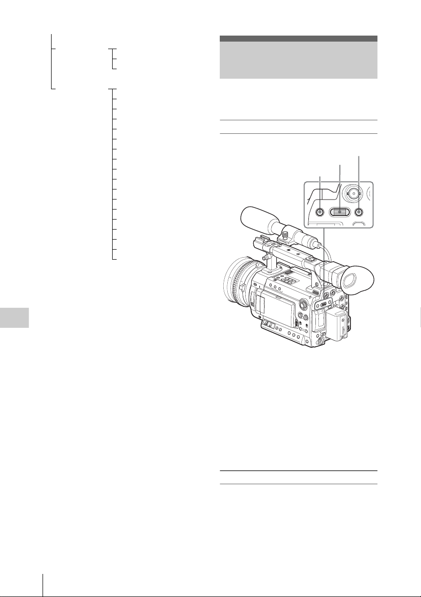
LENS FILE Information
Operation
Setting
Basic Menu Operations
Menu Configuration and Detailed Settings
OTHERS All Reset
Camera Data
Time Zone
Clock Set
Language
Assign Button
Tally
Hours Meter
IR Remote
Battery Alarm
Battery INFO
Genlock
Trigger Mode
System
Clip
Format Media
Version
Version Up
This section covers basic operations for setting
the Setup menu items.
Menu controls
CANCEL button
Jog dial
MENU button
MENU SEL/SET CANCEL
PICTURE PROFILE
AB
MENU button
To turn Menu mode to use Setup menus on/off.
Jog dial (SEL/SET dial)
When you turn the dial, the cursor moves up or
down, permitting you to select menu items or
setting values.
CANCEL button
To return to the previous layer of the menu. An
uncompleted change is canceled.
Basic Menu Operations
100
Displaying the Setup menu
Press the MENU button.
The menu icons appear on the screen.
The cursor is displayed on the icon of the menu
used last, and the corresponding menu item
selection area is displayed to the right.
 Loading...