

Page 1

4-276-624-14 (1)
Solid-State Memory
Camcorder
PMW-F3K
PMW-F3L
Supplement
© 2011 Sony Corporation
Page 2

Table of Contents
Foreword ....................................................................................3
Using an External Hard Disk ................................................... 3
Using a Media Adaptor ............................................................ 5
Operating via the REMOTE Connector ................................. 6
Using a Wi-Fi Adapter ........................................................... 10
Using the 3D-Link Function ................................................... 14
Setting the S-Log Gamma and Monitor Image .................... 17
Formats and Limitations of Outputs .................................... 20
Attaching the PHU-120R ............................................... 3
Formatting the PHU-120R ............................................. 4
Checking the Remaining Time Available for
Recording ................................................................. 4
Restoring the PHU-120R ............................................... 4
Formatting ...................................................................... 5
Operating the Menus of the Camcorder ......................... 6
Functions Operable via the REMOTE Connector ......... 8
Fixing the CBK-WA01 ................................................ 10
Making a Wi-Fi Connection ......................................... 10
Using the Web Menu ................................................... 12
Using Live Logging Function ...................................... 14
Preparations Before Recording .................................... 14
3D-Link Recording ...................................................... 15
Using the S-Log Gamma .............................................. 17
Setting the Monitor Image ........................................... 18
Video Formats and Output Formats ............................. 20
Limitations of Outputs ................................................. 35
2
Page 3
Foreword Using an External Hard
MENU
SEL/SET
CAN
O
N
S
L
O
T
S
E
L
E
C
T
O
FF
PICTURE P
A
B
D
C
IN
Disk
This supplement contains the following
supplementary information about the PMW-F3K/
F3L.
• Using an External Hard Disk
• Using a Media Adaptor
• Operating via the REMOTE Connector
• Using a Wi-Fi Adapter
• Using the 3D-Link function
• Setting S-Log gamma and monitor image
• Output Formats and Limitations
You can use an optional PHU-120R Professional
Hard Disk Unit with this camcorder.
Notes
• High-speed playback may not be properly
achieved with the PHU-120R.
• Slow Motion recording by the Slow & Quick
Motion recording function cannot be made with
the PHU-120R.
Attaching the PHU-120R
Recording/playback can be made using the PHU120R in the same manner as with SxS memory
cards if you connect the PHU connection cable of
the PHU-120R to an SxS memory card slot of the
camcorder.
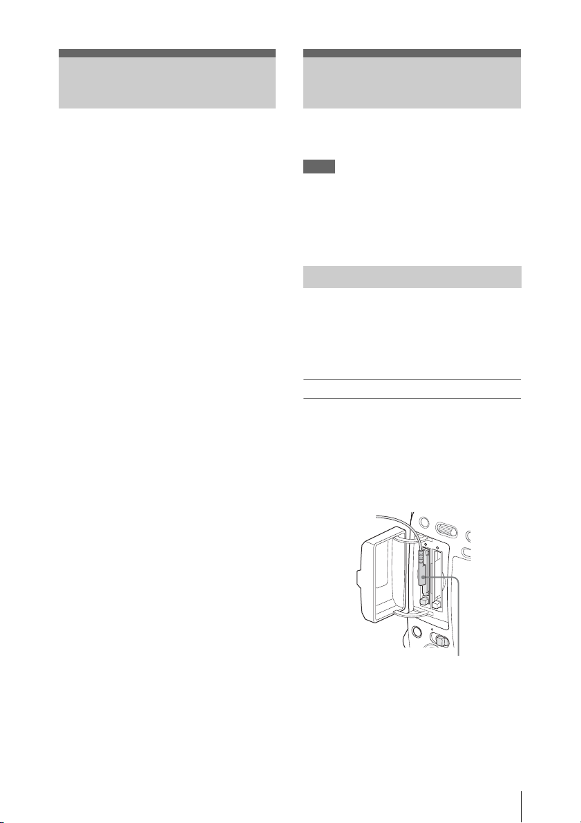
Connecting the PHU connection cable
1 Set the power switch of the camcorder
to the ON position.
2 Open the cover of the card slot block
and plug the PHU connection cable into
a slot.
Insert so that the cable extends upward.
3 Turn on the PHU-120R.
The POWER indicator of the PHU-120R
lights in green.
Subsequently, the access lamp of the
camcorder lights in red then changes to green
once the unit is ready for use.
Foreword / Using an External Hard Disk
3
Page 4
Notes
T
• The cover of the card slot block cannot be
closed with the PHU-120R connected.
• Bundle the cable so that it will not accidentally
get on nearby objects.
To disconnect the PHU connection cable
Operate in the same manner as when you remove
an SxS memory card from the slot.
Formatting the PHU-120R
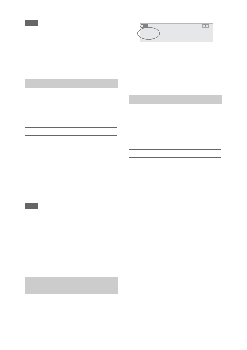
120min
A: 185 min
B : - - - min
Z99
The available time for recording with the current
video format (recording bit rate) is calculated
according to the remaining space of the hard disk
and displayed in time units of minutes.
The remaining capacity can also be checked in a
meter format on the BATTERY/MEDIA status
screen.
STBY
STBY
For a PHU-120R that is not formatted or that was
formatted with another system, the message
“Unsupported File System” is displayed on the
LCD monitor/viewfinder screen.
Format the PHU-120R as instructed below.
To execute formatting
Using “Format Media” of the OTHERS
menu, specify “Media(A)” (slot A) or
“Media(B)” (slot B) then select “Execute.”
On a confirmation message, select
“Execute” again.
Formatting begins.
An in-progress message and status bar (%) are
displayed, and the access lamp lights in red.
When formatting is completed, a completion
message is displayed for three seconds.
Notes
• Formatting for the PHU-120R on this
camcorder is “Quick Format” with which only
the managerial data are erased. To erase the
recording data completely, connect the unit to a
PC and perform “Full Format.”
• The PHU-120R to be used with this camcorder
must be formatted using the format function of
this camcorder. Any PHU-120R formatted with
another device must be formatted again with
this camcorder.
Restoring the PHU-120R
If an error occurs with data on the PHU-120R for
some reason, the hard disk must be restored.
If a PHU-120R that needs to be restored is
connected, a message that prompts you to execute
restoration is displayed on the LCD monitor/
viewfinder screen.
To restore the hard disk
Select “Execute” by turning the jog dial
then push the dial.
Restoration begins.
During restoration, an in-progress message and
status bar (%) are displayed, and the access lamp
is lit in red.
When restoration is completed, a completion
message is displayed for three seconds.
If restoration fails
• A PHU-120R on which an error occurred may
become usable again through reformatting.
• In some cases, only parts of clips cannot be
restored. Playback of the restored clips becomes
possible again.
Checking the Remaining Time Available for Recording
In E-E Display/Recording mode, the remaining
capacity (in minutes) of the PHU-120R
connected via a card slot is displayed on the LCD
monitor/viewfinder screen.
Using an External Hard Disk
4
Page 5
Using a Media Adaptor
Use of the optional MEAD-MS01 or MEADSD01 Media Adaptor permits you to insert a
“Memory Stick” (with MEAD-MS01) or an
SDHC card (with MEAD-SD01) to the SxS
memory card slot of the camcorder and use it for
recording and playback in the same way as with
an SxS memory card.
Usable “Memory Stick”
“Memory Stick PRO-HG Duo” HXA series
Usable SDHC card
Class 10 SDHC card
For details on use of the MEAD-MS01/SD01 Media
Adaptor, refer to the operating instructions of the
adaptor.
Notes
• High-speed playback may not be properly
achieved with a “Memory Stick” or an SDHC
card.
• Slow Motion recording by the Slow & Quick
Motion recording function cannot be made with
a “Memory Stick” or an SDHC card.
Formatting
When you use a “Memory Stick” or an SDHC
card with this camcorder, formatting is required.
A “Memory Stick” or an SDHC card to be used
with this camcorder must be formatted using the
format function of this camcorder.
It is also necessary to format a “Memory Stick” or
an SDHC card for use if a caution message is
displayed when you mount the “Memory Stick”
or SDHC card.
For a “Memory Stick” or an SDHC card that was
formatted with another system unsupported by
this camcorder, the message “Unsupported File
System” is displayed on the LCD monitor/
viewfinder screen.
Format the “Memory Stick” or SDHC card as
instructed below.
To execute formatting
Using “Format Media” of the OTHERS
menu, specify “Media(A)” (slot A) or
“Media(B)” (slot B) then select “Execute.”
On a confirmation message, select
“Execute” again.
Formatting begins.
An in-progress message and status bar (%) are
displayed, and the access lamp lights in red.
When formatting is completed, a completion
message is displayed for three seconds.
Note
In formatting, all data in a “Memory Stick” or an
SDHC card including protected images, are
erased and cannot be restored.
Connection between the camcorder and a PC
To use a “Memory Stick” or an SDHC card in
which data have been recorded with an XDCAM
EX-series product, insert it into the slot of the
camcorder and connect between the PC and this
camcorder using a USB cable.
To use a “Memory Stick” formatted with this
camcorder with other devices having a “Memory
Stick” slot
1. First make a backup copy of the data recorded
in the “Memory Stick.”
2. When the backup is done, format the “Memory
Stick” with the device to be used.
For details on the formatting method, refer to the
operating instructions of the device to be used.
To use an SDHC card formatted with this
camcorder with other devices having an SDHC
card slot
1. First make a backup copy of the data recorded
in the SDHC card.
2. When the backup is done, format the SDHC
card with the device to be used.
For details on the formatting method, refer to the
operating instructions of the device to be used.
• “Memory Stick” and are
trademarks of Sony Corporation.
• “Memory Stick PRO-HG Duo” and
are trademarks of
Sony Corporation.
Using a Media Adaptor
5
Page 6
Operating via the REMOTE Connector
When the optional RM-B750 / RM-B150 Remote
Control Unit or RCP-1000/1001 / RCP-1500/
1501/1503 Remote Control Panel is connected,
various settings of the camcorder can be
performed from the remote control device.
You can operate the menus of the camcorder and
monitor the picture on the display of the RMB750 or a video monitor connected via the
MONITOR connector of the remote control
device if you set the output of the camcorder to
SD by selecting SD SDI, SD HDMI i & HDV or
SD HDMI i & DVCAM under “SDI/HDMI/
i.Link I/O Select” of the VIDEO SET menu.
Connection
Using the remote cable (10 m) supplied with the
remote control device, connect between the
REMOTE connector of the camcorder and the
camera connector of the remote control device.
When you turn on the camcorder after the
connection, the camcorder enters Remote Control
mode.
Note
Use the RM-B750 of serial number 120000 or
higher.
Adjusting the camcorder from the remote
control device
Turn on the camcorder.
The Picture Profile function is activated,
automatically selecting Picture Profile 10.
From this status, you can control menu and
recording operations from the remote control
device.
For the functions that can be controlled from the
remote control devices, see “Functions Operable via
the REMOTE Connector” on page 8.
Notes
• Remote control operations cannot be made if
USB connection to the camcorder is enabled.
• Do not connect or disconnect the remote control
device when the camcorder is on.
• The following controls of the camcorder
become inoperative when the remote control
device is connected.
—GAIN switch
—WHITE BALANCE switch
—SHUTTER switch
—BARS/CAM button
—AUTO WHT BAL button
• The ECS frequency value displayed on the
Remote Control Unit may slightly differ from
that on the camcorder.
Releasing Remote Control mode
Turn off the camcorder and disconnect the remote
control device.
The settings on the controls on the camcorder
become valid.
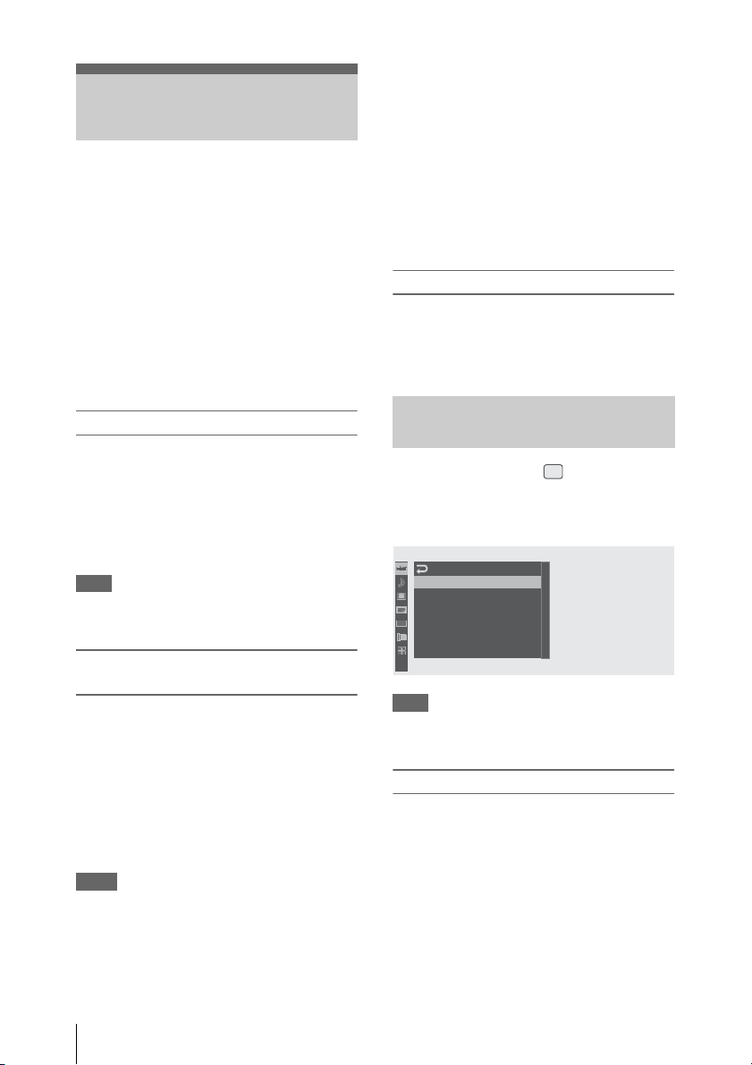
Operating the Menus of the Camcorder
In Remote Control mode, (the icon for the
Picture Profile menu) is displayed at the bottom
with the Setup menu icons, enabling you select
the Picture Profile menu from this screen.
C
AMERA SET
A
uto B
lack B
Setup
hutter
Bar T
Reduce
al.
ype
00:00
PP
Note
Gain
Shutter
Slow S
Color
Flicker
The menu items that cannot be set in Remote
Control mode are shaded and cannot be selected.
Operating the menu from the RM-B150
Set the camcorder to E-E Display mode then
proceed as follows.
B
B
B
:
B
Multi
PP
B
1 Set the DISPLAY switch to MENU.
The menu of the camcorder appears on the
monitor screen connected via the MONITOR
connector of the RM-B150.
2 Select and set the menu items using the
MENU SELECT knob and the
CANCEL/ENTER switch.
Operating via the REMOTE Connector
6
Page 7

3 When the settings are completed, set the
DISPLAY switch to ON or OFF to exit
the menu.
For details on operations of the RM-B150, refer to
the Operation Manual of the RM-B150.
Operating the menu from the RM-B750
Set the camcorder to E-E Display mode then
proceed as follows.
1 Press and light the MONITOR button
then press the VF MENU button.
The menu of the camcorder appears on the
RM-B750 display and the monitor screen
connected via the MONITOR connector of
the RM-B750.
2 Select and set the menu items, using the
MENU SELECT knob, ENTER button,
and CANCEL button.
3 When the settings are completed, press
the VF MENU button to exit the menu.
For details on operations of the RM-B750, refer to
the Operation Manual of the RM-B750.
Operating via the REMOTE Connector
7
Page 8
Functions Operable via the REMOTE Connector
When the camcorder is set to E-E Display mode,
the following functions can be made using the
B750 or RCP-1500/1501/1503) on the remote
control device, in addition to menu operations.
controls, the switches, or the touch panel (RM-
Function Operation on the
camcorder
Operation on
the RM-B150
Operation on
the RM-B750
Operation on
the RCP-1000/
1001, RCP1500/1501/1503
Menu ON/OFF MENU button yes yes yes
Master gain selection GAIN switch yes yes
Step gain selection yes
Color bar signal output
ON/OFF
Shutter ON/OFF SHUTTER switch +
Shutter speed selection CAMERA SET menu c Shutter yes yes yes
ECS ON/OFF SHUTTER switch +
ECS frequency selection CAMERA SET menu
Auto white balance AUTO WHT BAL button yes yes yes
Auto black balance CAMERA SET menu
White R/B level
adjustments
Black R/B level
adjustments
White balance memory
selection
Auto Tracing White
ON/OFF
Recording start/stop REC START/STOP button yes yes
Rec Review REC REVIEW button yes yes
Rec Review stop STOP button yes yes
Playback start PLAY/PAUSE button yes yes
Playback stop STOP button yes yes
Fast-forward playback F FWD button yes yes
Fast-reverse playback F REV button yes yes
Call signal ON/OFF
1)
When you press the CALL button on the RM-B750, the message “CALL” is displayed in the viewfinder of the
camcorder.
BARS/CAM button yes yes yes
CAMERA SET menu c Shutter
CAMERA SET menu c Shutter
c Shutter
c Auto Black Bal.
WHITE BALANCE switch yes yes yes
Assignable button (with
“ATW” assigned)
1)
yes yes yes
yes yes yes
yes yes yes
yes yes yes
yes yes yes
yes yes yes
yes yes yes
yes yes
Operating via the REMOTE Connector
8
Page 9
Adjustments of the Picture Profiles
The Picture Profile menu of the camcorder can be
operated from the remote control device in the
same manner as on the camcorder. In addition,
some items of the Picture Profile menu can also
be adjusted by using the menus or controls of the
remote control device.
For details on operations of the remote control
device, refer to the Operation Manual of the device.
Notes
• The following menu and knob/switch
operations on the remote control device are
enabled when the menu of the camcorder is not
displayed.
The changes become valid and reflected on the
Picture Profile menu.
• If the control knobs on the remote control
device is set to Absolute mode, the
corresponding items cannot be changed on the
Picture Profile menu.
Picture Profile item Operation on
the RM-B150
Operation on
the RM-B750
Operation on
the RCP-1000/
1001, RCP1500/1501/1503
Matrix Setting yes
Multi Matrix Setting yes
HD Detail
SD Detail
Skin Tone Detail Setting yes yes yes
Knee Setting yes
Gamma Level yes yes yes
Black yes yes yes
Black Gamma yes
Low Key SAT yes
Level yes
R-G, R-B, G-R, G-B, B-R, B-G yes
Axis yes
Hue yes
Saturation yes
Setting yes
Level yes yes yes
Frequency yes
Crispening yes
H/V Ratio yes
White Limiter yes
Black Limiter yes
Knee APT Level yes
Level yes yes yes
Area Indication yes
Saturation yes
Phase yes
Width yes
Auto Knee yes yes yes
Point yes yes yes
Slope yes yes yes
Knee SAT Level yes yes yes
Select yes
Operating via the REMOTE Connector
9
Page 10
Using a Wi-Fi Adapter
2
+
Mounting an optional CBK-WA01 Wi-Fi
Adapter on this camcorder allows a Wi-Fi
connection between a computer and the
camcorder.
For details on the CBK-WA01, refer to the Mounting
Instructions and Operating Instructions supplied
with the CBK-WA01.
Making a Wi-Fi connection between a computer
and the camcorder enables you to do the
following.
• Send planning metadata created on a computer
to the camcorder, and set names of clips to shoot
and shot marks for shooting.
• Send files including clips from the camcorder to
a computer, and edit them at the shooting
location.
Notes
• Check the firmware version of your camcorder
to make sure that the camcorder supports the
Wi-Fi adapter.
For details, contact your Sony dealer or your Sony
service representative.
• In order to use the Wi-Fi connection feature,
you must install a CBK-RGB01 RGB and SLOG Output Option.
When installing the CBK-RGB01, refer to the
Operating Instructions supplied with the CBKRGB01.
Fixing the CBK-WA01
Note
Before attaching or removing the CBK-WA01,
turn the power of the camcorder off.
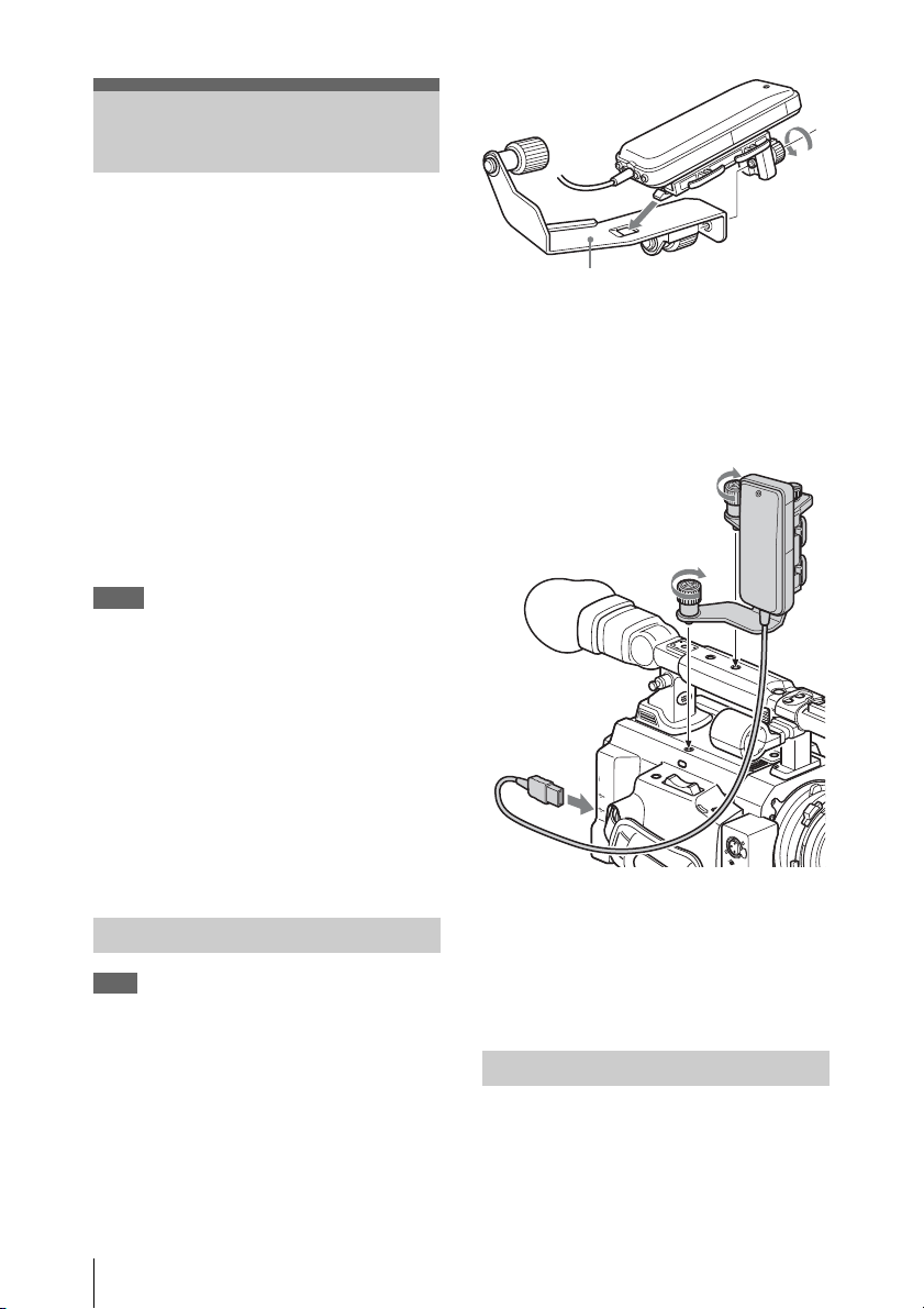
1 Hook the CBK-WA01 Wi-Fi Adapter to
the hole of the mounting bracket for the
CBK-WA01 (Part No. 4-410-322-01),
and secure the adapter with the screw.
Mounting bracket for the CBK-WA01
2 Remove the caps from the two accessory
mounting screw holes on the PMWF3K/F3L then tighten the screws of the
mounting bracket for the CBK-WA01.
Tighten the screws securely to hold the
bracket firmly in place.
2
S
T
A
R
T
/
S
R
T
E
O
C
P
A
S
S
I
G
N
6
AS
SIG
N 7
T
T
L
L
X
X
E
E
N
N
s
s
P
P
J
J
D
O
O
W
T
T
F
S
S
F
S
S
/
/
E
l
l
S
V
V
U
G
G
E
E
A
R
R
P
/
P
P
Y
A
L
P
j
j
V
V
E
E
R
R
MF
MF
A
A
/C
/C
S
S
R
R
A
A
B
H
D
M
I
O
U
T
L
I
N
K
(
H
D
V
/
D
V
3
)
R
E
M
O
T
E
S
P
A
R
E
REC REVIEW
E
X
P
A
F
N
O
D
C
E
U
D
S
W
T
B
ASSIG
N 8
A
U
D
C
I
O
H
I
N
1
M
IC
LIN
E
C
M
H
IC
-
3 Connect the USB cable of the CBK-
WA01 to the Option connector (USB A
connector) on the PMW-F3K/F3L.
For the mounting bracket for the CBK-WA01,
contact your Sony dealer or your Sony service
representative.
Making a Wi-Fi Connection
Two types of Wi-Fi connections are available. In
“ad hoc mode,” you can make a peer-to-peer WiFi connection between a computer and
camcorder. In “infrastructure mode,” you can
make Wi-Fi connections between a computer and
Using a Wi-Fi Adapter
10
Page 11
multiple camcorders via a wireless LAN access
point (building a LAN).
To make a network setting
Change settings under "Network" of the
OTHERS menu, as required.
Item Setting
DHCP To specify whether to acquire the
IP Address
Subnet Mask Subnet mask (factory default
Default Gateway Default gateway (factory default
User Name User name for log-in (factory
Password
a) The IP address determined by the DHCP server is
displayed here.
b) The password is displayed as “ * ”.
IP address automatically from a
DHCP server.
Enable: Acquire automatically.
Disable: Do not acquire
automatically (factory default
setting).
a)
IP address
(factory default
setting: 192.168.1.10)
setting: 255.255.255.0)
setting: 0.0.0.0)
default setting: admin)
b)
Password
for log-in (factory
default setting: pmw-f3)
When you have changed a setting
Select “Execute” under “Set” of the “Network”
menu.
When a confirmation message appears, select
“Execute” and press the jog dial.
To make a connection in ad hoc mode
1 Refer to “Settings on the Computer”
under “Making a Wi-Fi Connection to
Your Computer (Ad hoc Mode)” in the
Operating Instructions supplied with
the CBK-WA01 to make settings on the
computer.
2 Start a connection on the computer.
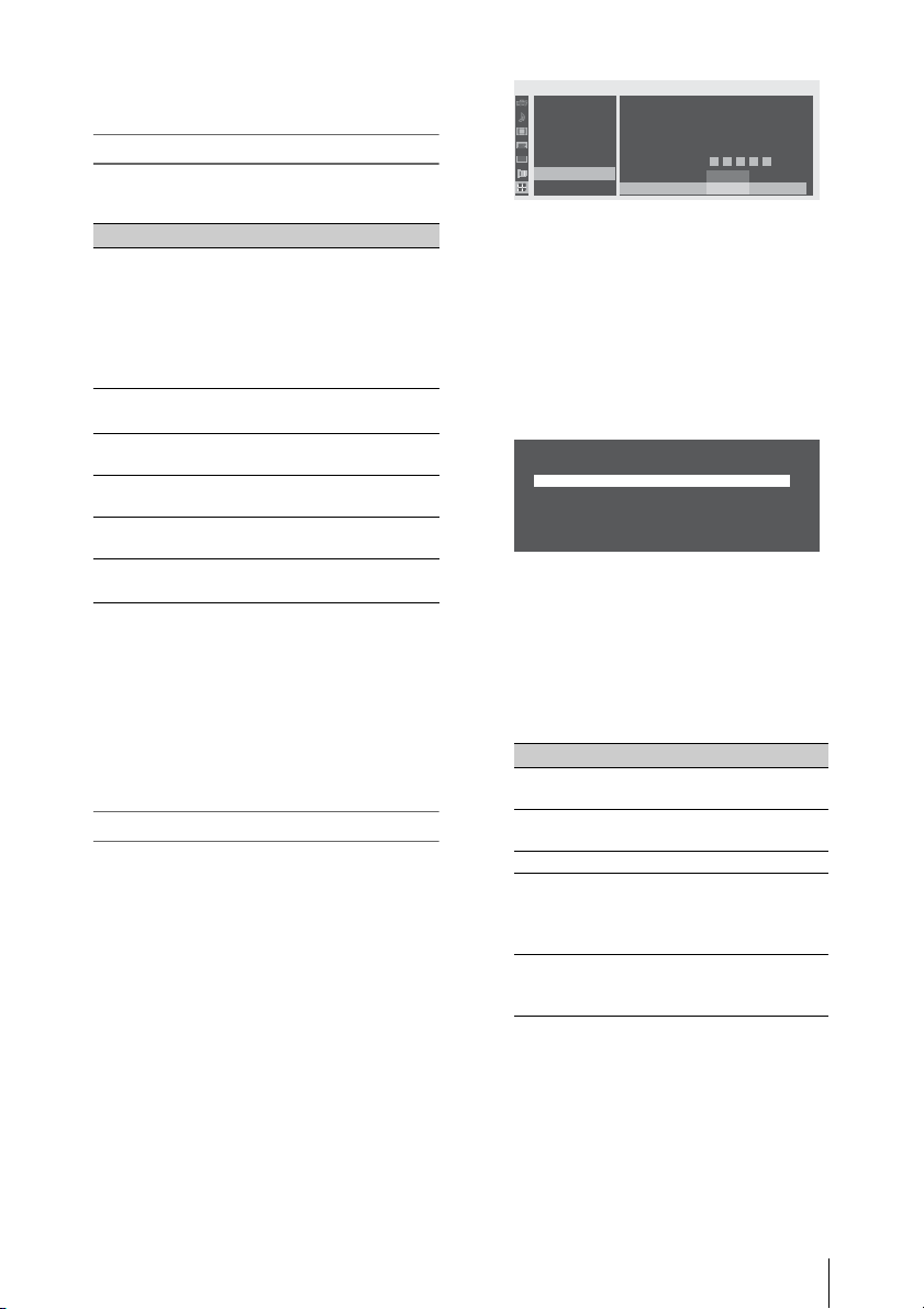
O
THE
RS
System
Clip
Copy All
Plan.Metadata
00:00
Network
Wi
Option
B
WEP Key Index
B
Input Select
B
Key
B
Set
B
Fi
Wi-Fi Status
B
Wireless Mode
B
Wi
-
-
Fi
: 1
:
HEX26
:
*************
: [ ]
:
Enable
Disable
5 Select “Network Type” then select
“Adhoc.”
6 Select “Scan Networks” then select
“Execute.”
The camcorder starts scanning for a network
connection.
When networks are detected, the
NETWORK SCAN list appears.
NETWORK SCAN
01.WF1 Adhoc Lvl=71 11g
7 Turn the jog dial to select a network and
press the jog dial.
The OTHERS menu appears again.
8 Confirm that the settings of “Wi-Fi”
conform to the network setting on the
computer.
Item Setting
SSID
(network name)
Network Type
(connection mode)
Ch (channel) 1
Authentication
(network
authentication)
Encryption
(data encryption)
Selected network name
“Adhoc”
Depending on the settings on
the computer, “Open,”
“Shared,” “WPA,” or
“WPA2”
Depending on the settings on
the computer, “Disable,”
“WEP,” “TKIP,” or” AES”
3 Select “Wi-Fi” of the OTHERS menu.
4 Select “Wi-Fi” with the jog dial then
select “Enable.”
Using a Wi-Fi Adapter
11
Page 12

Item Setting
WEP Key Index
(key index)
Input Select
(key input format)
1 when “Encryption” is set to
“WEP”
Depending on the network
key (or security key),
“ASCII5,” “ASCII13,”
“HEX10,” or “HEX26” when
“Encryption” is set to “WEP”
or
“ASCII8-63” or “HEX64”
when “Encryption” is set to
“TKIP” or “AES.”
9 Select “Key” and set it to the network
key (or security key) set on the
computer and press the jog dial.
10 Select “Execute” under “Set” and press
the jog dial.
The message “Wi-Fi Setting Executing…”
appears and the camcorder starts connection.
If the connection to the computer is
complete, the message changes to “Wi-Fi
Setting OK.”
Black squares appear in the “Wi-Fi Status”
column to show the connection status. (The
number of squares shows the level of
connection status.) In the “Wireless Mode”
column, the IEEE802.11 standard of the
established connection appears (802.11b,
802.11g or 802.11n).
Tip
It is also possible to make a connection by
accessing a network connection started on the
camcorder from the computer.
To terminate the Wi-Fi connection
Terminate the Wi-Fi connection on the computer.
To revert to the default settings (reset)
If you have trouble making a connection or you
want to start over, you can reset your Wi-Fi
connection settings to the default settings.
Select “Net Config Reset” under “Network” of
the OTHERS menu and press the jog dial.
If the reset is executed, the message “Net Config
Reset Done” appears.
The camcorder attempts to connect to the network
using a MAC address as the SSID.
To make a connection in infrastructure
mode
Setting up the wireless LAN access point
The following settings are required.
• Network ID (SSID)
• Encryption method (Encryption)
• Network key (Key)
For details on setting up the wireless LAN access
point, refer to the manual supplied with the wireless
LAN access point.
To find and connect to a wireless LAN from the
camcorder
Perform the same procedure in “To make a
connection in ad hoc mode” (page 11), excluding
the following.
• Do not perform steps 1 and 2.
• Set "Network Type" to "Infra" in step 5.
• The “Wi-Fi” settings made in step 8 change as
follows:
Item Setting
SSID
(network name)
Network Type
(connection mode)
Ch (channel) Automatically set
Authentication
(network
authentication)
Encryption
(data encryption)
WEP Key Index
(key index)
Input Select
(key input format)
Selected network name
“Infra”
Depending on the settings for the
access point, “Open,” “Shared,”
“WPA,” or “WPA2”
Depending on the settings for the
access point, “Disable,” “WEP,”
“TKIP,” or “AES”
1 when “Encryption” is set to
“WEP”
Depending on the network key (or
security key), “ASCII5,”
“ASCII13,” “HEX10,” or
“HEX26” when “Encryption” is
set to “WEP” or
“ASCII8-63” or “HEX64” when
“Encryption” is set to “TKIP” or
“AE S.”
Using the Web Menu
You can operate the Web menu built into the
camcorder from a computer when it is connected
to the camcorder via a Wi-Fi connection.
Using the Web menu, you can check the
information and settings for the camcorder and
upload the planning metadata file.
Using a Wi-Fi Adapter
12
Page 13

Note
Accessing the Web menu during recording or
playback is not possible. (Sending/receiving files
via the Wi-Fi connection is also not possible.)
Example of Web menu
Product Information
• Model name
• Serial No.
Network
• MAC Address
• IP Address
• Subnet Mask
Wi-Fi Status
• Wireless Mode
• SSID
• Type
• Channel
• Authentication (network authentication)
• Data Encryption (data encryption)
Planning Metadata
Clicking “Upload” displays the Planning
Metadata Upload screen which allows upload of a
planning metadata file (see page 13).
Note
The configuration of items displayed in the Web
menu varies depending on the browser you are
using.
To display the Web menu
1 Launch a web browser on the computer
and navigate to “http://<camcorder’s
IP address> (“IP Address” setting
under “Network” of the OTHERS
menu).”
Example (when the IP address is
”192.168.1.10”): Type
“http://192.168.1.10/” in the address bar.
If the connection is complete, a dialog
appears asking you to enter the user name
and password.
2 Enter the user name and password then
click OK.
User name: admin
Password: pmw-f3 (lowercase model name)
To upload a planning metadata file
Note
Uploading a plannin g metadata file is not possible
when Picture Cache Recording is set to On or the
menu screen or thumbnail screen is displayed.
1 Insert a medium such as an SxS
memory card.
2 Click “Upload” in the Web menu.
The Planning Metadata Upload screen
appears.
3 Click “Select” to show the Choose File
dialog.
4 Select the planning metadata file you
wish to upload and then click “Open.”
The path of the selected file appears.
5 Click “Execute.”
Using a Wi-Fi Adapter
13
Page 14

The planning metadata file is loaded into the
camcorder’s memory and stored in the
medium.
“OK” appears in the Status field when the
transfer is complete.
Using the 3D-Link Function
To upload a planning metadata file
automatically
In the planning metadata file you want to load
automatically, add a “load” property to the
PlanningMetadata tag and set the value of the
property to “true.”
When you display the Web menu and insert a
medium, the planning metadata file is
immediately loaded into the camcorder’s
memory.
Example: <PlanningMetadata …
version="1.00">
sp
For details on the planning metadata, refer to the
Operating Instructions supplied with the camcorder.
load=”true”
sp
Using Live Logging Function
The Live Logging function allows you to send
and receive metadata between this camcorder and
a computer.
The following operations are available on the
computer.
• Add and edit metadata (titles, comments,
essence marks, etc.)
• Transfer the added or edited metadata from the
computer back to the camcorder to write to the
original medium.
The 3D-Link function enables synchronization of
the signal phase (genlock), timecodes, and start/
stop of recording between two PMW-F3K/F3L
units connected via an exclusive cable.
Specifying one unit as the main unit and the other
as the sub unit, you can use the main unit for
shooting the left-eye view and the sub unit for
shooting the right-eye view for 3D images.
When the software version of the camcorder is
1.20 or higher, the 3D-Link function can be
enabled by installing the separately available
CBK-3DL01 3D-Link Option.
For details on the installation method, refer to the
Operating Instructions supplied with the CBK3DL01.
Preparations Before Recording
Connecting the camcorders
1 Connect two PMW-F3K/F3L units with
an appropriate cable.
Connect the SPARE connector of one unit to
that of the othe r unit, using the 3D-Link cable
supplied with the CBK-3DL01.
Note
When connecting, turn the camcorders off.
The Live Logging function is available any time
during recording.
Using the 3D-Link Function
14
Page 15

3D-Link cable
to SPARE
4 Specify one PMW-F3K/F3L unit as the
main unit and the other as the sub unit,
using “Mode” of “3D-Link” of the
OTHERS menu.
Main(L): Main unit
Sub(R): Sub unit
When the settings are made, simultaneous
processing for the main and sub unit begins.
When the simultaneous processing is
completed, the message “3D-Link
Connecting” disappears and 3D-Link
recording is enabled.
Note
When you change the “Mode” setting of
“3D-Link” from “Off” to “Main(L)” or
“Sub(R),” the message “3D-Link
Connecting” appears. Recording cannot be
started while this massage is displayed.
to SPARE
2 Set two PMW-F3K/F3L units to the
same recording video format, using
“Format” of “System” of the OTHERS
menu.
3 Set the output signals from two PMW-
F3K/F3L units to the same format,
using “SDI/HDMI/i.Link I/O Select” of
the VIDEO SET menu.
Note
The 3D-Link function does not operate under the
conditions listed below. Select other format
settings.
• “Format” of “System” of the OTHERS menu is
set to SP 1440/23.98P, DVCAM59.94i,
DVCAM29.97P, DVCAM50i, or DVCAM25P.
• “Format” of “System” of the OTHERS menu is
set to HQ 1920/23.98P or HQ 1440/23.98P and
"23.98P Output" of the VIDEO SET menu is set
to 59.94i (2-3 Pull Down).
• “Format” of “System” of the OTHERS menu is
set to HQ 1920/23.98P or HQ 1440/23.98P and
“SDI/HDMI/i.Link I/O Select” of the VIDEO
SET menu is set to other than HD HDMI and
HD SDI & HDMI.
• “SDI/HDMI/i.Link I/O Select” of the VIDEO
SET menu is set to SD-HDMI P.
For clips recorded on the main unit, “L” is
automatically added to the end of the clip names.
For clips recorded on the sub unit, “R” is
automatically added to the end the clip names.
For 3D recording, be sure to use the main unit for
left-eye view and the sub unit for right-eye view.
Copying the camera settings
When 3D-Link is active, various settings of the
main unit can be copied to the sub unit. This is
useful for aligning shooting conditions between
the two units.
On the main unit, call “Send Main Data” of
“3D-Link” of the OTHERS menu then
select “Execute.”
The setup menu and picture profile menu settings
and the white balance value of the main unit are
copied to the sub unit.
If a remote control unit is connected, the black R/
B levels adjusted with the remote control unit are
also copied.
3D-Link Recording
Recording start/stop operations are made on the
main unit. Recording on the sub unit is started and
stopped in synchronization with the main unit.
Using the 3D-Link Function
15
Page 16

1 Press the REC START/STOP button on
the main unit to start recording.
Recording on the sub unit automatically
begins.
2 To stop recording, press the REC
START/STOP button on the main unit
again.
Recording on the sub unit also stops
automatically.
Notes
• For 3D-Link recording, use SxS memory cards
of the same type and same size for the main and
sub units.
• If recording cannot be started on either of the
main or sub unit, recording start operation is
rejected.
• If recording stops on either of the main or sub
unit, recording on the other unit also stops.
Rec Review
When 3D-Link is active, pressing the REC
REVIEW button on the main unit after stopping
recording starts Rec Review on the main and sub
units in synchronization.
Linking functions
When 3D-Link is active, the following functions
of the sub unit are always synchronized with or
linked to those on the main unit. Different settings
between units are not allowed.
—Time code and signal phase
—Interval Rec, Frame Rec, and S&Q Motion
settings
—Electronic Shutter (including Slow Shutter)
settings
Linking of the iris, focus, or/and zoom
positions
If the same Sony power zoom lens (such as an
optional SCD-Z18X140) is mounted on both the
main unit and the sub unit, you can link the iris,
focus, and/or zoom positions on the sub unit to
those on the main unit when 3D-Link is active
(with a camcorder with software version 1.30 or
higher).
Constant linking
Set the following items under “3D-Link” of the
OTHERS menu.
Item Setting
Iris Position Sync On: To link the iris position on the
Focus Position
Sync
Zoom Position
Sync
Iris Offset To adjust the lens iris on the sub
sub unit to that on the main unit.
Off: To not link the iris position.
On: To link the focus position on
the sub unit to that on the main
unit.
Off: To not link the focus position.
On: To link the zoom position on
the sub unit to that on the main
unit.
Off: To not link the zoom position.
unit to that on the main unit when
the lenses on both units are linked
to move. The adjustable range is
from –99 to +99.
Temporary linking
When “Iris Sync,” “Focus Sync, ” or “Zoom
Sync” has been assigned to an assignable button
on the main unit, you can temporarily link to
adjust the iris, focus, or zoom position on the sub
unit to that on the main unit.
Function Description
Iris Sync To temporarily link the iris
Focus Sync To temporarily link the focus
Zoom Sync To temporarily link the zoom
Notes
position on the sub unit to that on
the main unit.
position on the sub unit to that on
the main unit.
position on the sub unit to that on
the main unit.
• If “Iris Position Sync,” “Focus Position Sync,”
or “Zoom Position Sync” under “3D-Link” of
the OTHERS menu is set to “On” for constant
linking, pressing the assignable button to which
the corresponding linking function is assigned
does not activate temporary linking. Set the
constant linking function to “Off” for activating
the temporary linking.
• The linking function of this unit does not
guarantee synchronizing in the same phase.
Compensating the sensitivity difference
When the CBK-3DL01 3D-Link Option is
installed, you can finely adjust the sensitivity for
each of the ND filter positions individually, using
“ND Adjustment” of the OTHERS menu. It is
Using the 3D-Link Function
16
Page 17

effective for compensating the sensitivity
difference between the main and sub units.
Item Setting
ND Clear Adjust the sensitivity with the ND
FILTER switch set to OFF (no ND
filter) in the range of 0 to 999.
ND 1 (1/8) Adjust the sensitivity with the ND
FILTER switch set to 1 (1/8 ND
filter) in the range of 0 to 999.
ND 2 (1/64) Adjust the sensitivity with the ND
FILTER switch set to 2 (1/64 ND
filter) in the range of 0 to 999.
Restrictions in 3D-Link recording
There are the following restrictions in 3D-Link
recording:
When 3D-Link is active
• Timecode of the sub unit cannot be set to a
format different from that of the main unit.
Signal input to the TC IN connector of the sub
unit becomes invalid.
• Signal phase of the sub unit cannot be set to a
state different from that of the main unit. Signal
input to the GENLOCK IN connector of the sub
unit becomes invalid.
When “Mode” o f “3D-Link” of t he OTHERS menu
is set to “Main(L)” or “Sub(R)”
• Playback and thumbnail display are disabled.
• Image input via the i.LINK connector is
disabled.
• Recording start/stop operations on a device
connected to the i.LINK connector are not
performed even if “Trigger Mode” of the
OTHERS menu is set to “Both” or “External.”
• The ATW (Auto-Tracing White balance), AGC
(Automatic Gain Control), Auto Shutter, Auto
Knee, and Flicker Reduction functions cannot
be used.
• Store/load operations of all the menu setting
values to/from an SxS memory card using
“Camera Data” of the OTHERS menu are
disabled.
When “Mode” o f “3D-Link” of t he OTHERS menu
is set to “Sub(R)”
• The camcorder cannot be operated from the
supplied IR Remote Commander.
• Planning metadata cannot be used.
Setting the S-Log Gamma and Monitor Image
When you install a CBK-RGB01 RGB and SLOG Output Option on a camcorder whose
software version is 1.1 or higher, you can use the
S-Log gamma and MLUT (Monitor Look Up
Table) features.
For details on the installation procedure, refer to the
Operating Instructions supplied with the CBKRGB01.
Using the S-Log Gamma
Sony-Log (S-Log in subsequent text) enables
imaging in abundant layers from shadow detail to
highlight by enhancing the dynamic range up to
800% to reduce blocked-out shadows and blownout highlights.
In conventional video shooting, image creation is
performed while observing the master monitor
screen on the spot. However, in recording on
negative film, the exposure is decided using a
light meter, and color correction is performed in
post-production for final image creation. The
wide latitude of negative film makes it possible.
While inheriting such workflow with negative
film, S-Log achieves the “Digital-Negative”
workflow optimal for digital processing.
S-Log EI (Exposure Index) mode
S-Log EI mode is a vailable with a camcorder with
software version 1.20 or higher.
This mode permits you to perform shooting by
selecting the ISO sensitivity in the range of 800 to
3200, using a light meter.
As the master gain of the camera is fixed in this
mode, increasing the sensitivity darkens images
for output signal. In the same manner as in
sensitizing recording with film cameras, the gain
is increased to the appropriate level in postproduction for images recorded dark. Although
the HD-SDI Dual-Link or 3G-SDI output images
become dark, recording with an appropriate level
is enabled by applying an LUT to the HD SDI
output, LCD panel indications, and images to be
recorded on an SxS memory card, depending on
the settings in EI mode.
Setting the S-Log Gamma and Monitor Image
17
Page 18

Increasing the gain in post-production makes the
S/N worse with high sensitivity, but the dynamic
range for highlight areas can be enhanced. As this
camcorder has superior S/N characteristics,
image creation with low noise is possible even in
high-sensitivity recording. While the S-Log
gamma of the camcorder is designed for
recording with ISO800 as the proper exposure, SLog EI mode is quite effective when placing a
higher priority on highlights.
To set to S-Log gamma
Select one of the following settings under “DualLink & Gamma Select” of the VIDEO SET menu:
—1.5G YPbPr422 & S-Log
—1.5G RGB444 & S-Log
—3G YPbPr422 & S-Log
1)
1)
—3G RGB444 & S-Log
1)
Available with a camcorder with software version
1.30 or higher.
Limitations of using S-Log gamma
• The S-Log gamma output is a special setting for
shooting, which is different from the video
gamma output. This setting is applied to all
videos to be recorded on the SxS memory card
inserted into the camcorder and those to be
output from all output connectors, including
Dual-Link output connectors.
• When S-Log gamma is selected, the following
functions are set to off:
— TLCS (AGC, Auto Shutter), ATW, Offset
White, Flicker Reduce, flare compensation,
linear matrix, Multi Matrix, Detail, Skin
Tone Detail, Knee.
• When S-Log gamma is selected, white balance
is fixed to Preset White, and auto white-balance
adjustment cannot be executed.
• When S-Log gamma is selected, the following
items are fixed to a specified value:
—Preset White: 3200K (switching between
3200K and 5600K with the 5600K CC filter
is possible)
—Black (master black level): ±0
—Black Gamma: ±0
—Low Key SAT: ±0
2)
The “S-Log White ADJ (R Offset, B Offset)” items of
the CAMERA SET menu permit you to adjust
individual variability of preset white (Software
version 1.20 or higher).
2)
Setting the Monitor Image
As an image using S-Log gamma has low
contrast, it may be unsuitable for image checking
at the shooting location. MLUT (Monitor Look
Up Table) converts the contrast of the image
recorded on the camcorder and the output image
except Dual-Link output (image output from the
HD/SD SDI, HDMI OUT i.LINK, or VIDEO
OUT connector) to produce an image suitable for
checking. Use MLUT when you shoot images
using S-Log gamma without any adjustments, on
the assumption that the images will be output as
Dual-Link output and recorded on an external
device to be processed to post-production.
Notes
• If the setting of “S-Log LUT Select” of the
VIDEO SET menu is other than “Off,” MLUT
is applied to images recorded on the camcorder.
• MLUT conversion does not affect Dual-link
output.
• MLUT can be used only for the output with SLog gamma.
The camcorder is provided with four preset
LUTs. In addition to the preset LUTs, LUTs that
the user has created independently can be loaded.
A user LUT must be created with
CvFileEditor
via an SxS memory card.
For details, refer to “CvpFileEditor V4.20 User
Guide.”
You can download the latest version of
CvpFileEditor from the“eCSite” software
download site for the professional and business
products of Sony Corporation.
Note
The camcorder supports user LUT data of RGB
10-bit format. LUT data of 12-bit format or
having different RGB values cannot be managed
by the camcorder.
CvpFileEditor is a trademark of Sony Corporation.
1)
To select MLUT
When selecting MLUT other than S-Log EI mode
Set “S-Log LUT” of the VIDEO SET menu to
“On” then select the desired MLUT with “S-Log
LUT Select.”
TM 1)
and loaded into the camcorder
Setting the S-Log Gamma and Monitor Image
18
Page 19

“S-Log LUT
Setting
Select” item
Off MLUT not applied (original S-
P1: 709 (800%) Gamma with dynamic range
P2: HG8009G40 Hypergamma with 800%
P3: HG8009G33 Hypergamma with 800%
P4: 709 (180%) Gamma with 87% knee point and
U1: 709 (180%) User LUTs
U2: 709 (180%)
U3: 709 (180%)
U4: 709 (180%)
U5: 709 (180%)
Log gamma is output)
extended to 800% on basis of
ITU-R709
dynamic range, 109% white limit,
and 40% video output for the18%
gray card
dynamic range, 109% white limit,
and 33% video output for the18%
gray card
180% dynamic range on basis of
ITU-R709
When selecting MLUT of S-Log EI mode
Set “S-Log LUT” of the VIDEO SET menu to
“On” then select the desired MLUT with “S-Log
EI Select” after setting “S-Log EI Mode” to “On.”
“S-Log EI
Setting
Select” item
800EI ITU-R709-conversion LUT
1000EI ITU-R709-conversion LUT
1250EI ITU-R709-conversion LUT
1600EI ITU-R709-conversion LUT
2000EI ITU-R709-conversion LUT
adjusted to the proper brightness
depending on 800EI (equivalent to
0 dB gain)
adjusted to the proper brightness
depending on 1000EI (equivalent
to 2 dB gain)
adjusted to the proper brightness
depending on 1250EI (equivalent
to 4 dB gain)
adjusted to the proper brightness
depending on 1600EI (equivalent
to 6 dB gain)
adjusted to the proper brightness
depending on 2000EI (equivalent
to 8 dB gain)
“S-Log EI
Setting
Select” item
2500EI ITU-R709-conversion LUT
3200EI ITU-R709-conversion LUT
adjusted to the proper brightness
depending on 2500EI (equivalent
to 10 dB gain)
adjusted to the proper brightness
depending on 3200EI (equivalent
to 12 dB gain)
To load user LUT data
To load user LUT data stored in an SxS memory
card to the camcorder, select “Recall” under
“LUT Memory” of the OTHERS menu.
User LUT data 1 to 5 recorded on the SxS
memory card are loaded into the memory of the
camcorder collectively.
To store user LUT data
To store user LUT data stored in the memory of
the camcorder into an SxS memory card, select
“Store” under “LUT Memory” of the OTHERS
menu.
User LUT data 1 to 5 stored on the camcorder are
loaded into the SxS memory card collectively.
Directory for storing user LUT data
The user LUT data are stored in the following
directly:
Folder path: /SONY/PRO/CAMERA/HD_CAM/
File name: 00000001.lut, 00000002.lut,
00000003.lut, 00000004.lut, 00000005.lut
(The last number 1 to 5 corresponds to user LUT
number U1 to U5.)
Setting the S-Log Gamma and Monitor Image
19
Page 20

Formats and Limitations of Outputs
Video Formats and Output Formats
Output formats of the SDI OUT connector
The format of serial digital signals fed from the
SDI OUT connector depends on the related Setup
menu settings or the format of the clip to be
played, as shown below.
In E-E Display/Recording mode
“Country” setting of the OTHERS menu’s “System”: NTSC Area/NTSC(J) Area
OTHERS menu “System”:
“Format” setting
HQ 1920/59.94i
HQ 1920/29.97P
HQ 1920/23.98P
(23.98P Output:
59.94i(2-3PullDown))
HQ 1920/23.98P
(23.98P Output: 23.98PsF)
HQ 1440/59.94i
HQ 1440/29.97P
HQ 1440/23.98P
(23.98P Output:
59.94i(2-3PullDown))
HQ 1440/23.98P
(23.98P Output: 23.98PsF)
SP 1440/59.94i
SP 1440/23.98P
HQ 1280/59.94P
HQ 1280/29.97P
HQ 1280/23.98P
DVCAM59.94i SQ/EC “SDI/HDMI/i.LINK I/O Select” invalid
DVCAM29.97P SQ/EC
1)
59.94i provided through 2-3 pulldown of 23.98P
HD SDI SD SDI
1920
1920
1920
1920
1920
1920
1920
1920
1920
1920
1280
1280
1280
VIDEO SET menu “SDI/HDMI/i.LINK I/O Select” setting
×1080/59.94i 720×480/59.94i
×1080/29.97PsF 720×480/29.97PsF
×1080/59.94i
×1080/23.98PsF
×1080/59.94i 720×480/59.94i
×1080/29.97PsF 720×480/29.97PsF
×1080/59.94i
×1080/23.98PsF
×1080/59.94i 720×480/59.94i
×1080/59.94i
×720/59.94P 720×480/59.94i
×720/59.94P
×720/59.94P
2)59.94i provided through conversion from 59.94P
3)59.94P provided by outputting each frame of 29.97P two times
4)59.94P provided by repeating each frame of 23.98P two or three times
No signal is fed out from the SDI OUT connector
when “SDI/HDMI/i.LINK I/O Select” of the
VIDEO SET menu is at any setting other than
“HD SDI” and “SD SDI.”
SDI OUT output format
1)
720×480/59.94i
1)
720×480/59.94i
1)
3)
4)
720×480/59.94i
720×480/29.97PsF
720×480/59.94i
720
×480/59.94i
720
×480/29.97PsF
1)
1)
1)
2)
1)
Formats and Limitations of Outputs
20
Page 21

“Country” setting of the OTHERS menu’s “System”: PAL Area
OTHERS menu “System”:
“Format” setting
HQ 1920/50i
HQ 1920/25P
HQ 1440/50i
HQ 1440/25P
SP 1440/50i
HQ 1280/50P
HQ 1280/25P
DVCAM50i SQ/EC “SDI/HDMI/i.LINK I/O Select” invalid
DVCAM25P SQ/EC
50i provided through conversion from 50P
1)
HD SDI SD SDI
1920
1920
1920
1920
1920
1280
1280
VIDEO SET menu “SDI/HDMI/i.LINK I/O Select” setting
×1080/50i 720×576/50i
×1080/25PsF 720×576/25PsF
×1080/50i 720×576/50i
×1080/25PsF 720×576/25PsF
×1080/50i 720×576/50i
×720/50P 720×576/50i
2)
×720/50P
SDI OUT output format
720×576/25PsF
720
×576/50i
×576/25PsF
720
1)
2)50P provided by outputting each frame of 25P two times
In Thumbnail Screen mode
“Country” setting of the OTHERS menu’s “System”: NTSC Area/NTSC(J) Area
OTHERS menu “System”:
“Format” setting
HQ 1920/59.94i
HQ 1920/29.97P
HQ 1920/23.98P
(23.98P Output:
59.94i(2-3PullDown))
HQ 1920/23.98P
(23.98P Output: 23.98PsF)
HQ 1440/59.94i
HQ 1440/29.97P
HQ 1440/23.98P
(23.98P Output:
59.94i(2-3PullDown))
HQ 1440/23.98P
(23.98P Output: 23.98PsF)
SP 1440/59.94i
SP 1440/23.98P
HQ 1280/59.94P
HQ 1280/29.97P
HQ 1280/23.98P
DVCAM59.94i SQ/EC “SDI/HDMI/i.LINK I/O Select” invalid
DVCAM29.97P SQ/EC
59.94i provided through 2-3 pulldown of 23.98P
1)
HD SDI SD SDI
1920
1920
1920
1920
1920
1920
1920
1280
VIDEO SET menu “SDI/HDMI/i.LINK I/O Select” setting
×1080/59.94i 720×480/59.94i
×1080/59.94i
×1080/23.98PsF
×1080/59.94i
×1080/59.94i
×1080/23.98PsF
×1080/59.94i
×720/59.94P
SDI OUT output format
1)
1)
Formats and Limitations of Outputs
21
Page 22

“Country” setting of the OTHERS menu’s “System”: PAL Area
OTHERS menu “System”:
“Format” setting
HQ 1920/50i
HQ 1920/25P
HQ 1440/50i
HQ 1440/25P
SP 1440/50i
HQ 1280/50P
HQ 1280/25P
DVCAM50i SQ/EC “SDI/HDMI/i.LINK I/O Select” invalid
DVCAM25P SQ/EC
HD SDI SD SDI
1920
1280
VIDEO SET menu “SDI/HDMI/i.LINK I/O Select” setting
×1080/50i 720×576/50i
×720/50P 720×576/50i
SDI OUT output format
720
×576/25PsF
×576/50i
720
720
×576/25PsF
720
×576/50i
720
×576/25PsF
720
×576/50i
×576/25PsF
720
1)
In Clip Playback mode
“Country” setting of the OTHERS menu’s “System”: NTSC Area/NTSC(J) Area
Video format of playback
clip
HQ 1920/59.94i
HQ 1920/29.97P
HQ 1920/23.98P
(23.98P Output:
59.94i(2-3PullDown))
HQ 1920/23.98P
(23.98P Output: 23.98PsF)
HQ 1440/59.94i
HQ 1440/29.97P
HQ 1440/23.98P
(23.98P Output:
59.94i(2-3PullDown))
HQ 1440/23.98P
(23.98P Output: 23.98PsF)
SP 1440/59.94i
SP 1440/23.98P
HQ 1280/59.94P
HQ 1280/29.97P
HQ 1280/23.98P
DVCAM59.94i SQ/EC “SDI/HDMI/i.LINK I/O Select” invalid
DVCAM29.97P SQ/EC
1)
59.94i provided through 2-3 pulldown of 23.98P
HD SDI SD SDI
1920
1920
1920
1920
1920
1920
1920
1920
1920
1920
1280
1280
1280
VIDEO SET menu “SDI/HDMI/i.LINK I/O Select” setting
×1080/59.94i 720×480/59.94i
×1080/29.97PsF 720×480/29.97PsF
×1080/59.94i
×1080/23.98PsF
×1080/59.94i 720×480/59.94i
×1080/29.97PsF 720×480/29.97PsF
×1080/59.94i
×1080/23.98PsF
×1080/59.94i 720×480/59.94i
×1080/59.94i
×720/59.94P 720×480/59.94i
×720/59.94P
×720/59.94P
SDI OUT output format
1)
1)
720×480/59.94i
1)
720×480/59.94i
3)
720×480/29.97PsF
4)
720×480/59.94i
720×480/59.94i
720
×480/59.94i
720
×480/29.97PsF
1)
1)
1)
2)
1)
2)59.94i provided through conversion from 59.94P
3)59.94P provided by outputting each frame of 29.97P two times
4)59.94P provided by repeating each frame of 23.98P two or three times
Formats and Limitations of Outputs
22
Page 23

“Country” setting of the OTHERS menu’s “System”: PAL Area
Video format of playback
clip
HQ 1920/50i
HQ 1920/25P
HQ 1440/50i
HQ 1440/25P
SP 1440/50i
HQ 1280/50P
HQ 1280/25P
DVCAM50i SQ/EC “SDI/HDMI/i.LINK I/O Select” invalid
DVCAM25P SQ/EC
50i provided through conversion from 50P
1)
HD SDI SD SDI
1920
1920
1920
1920
1920
1280
1280
VIDEO SET menu “SDI/HDMI/i.LINK I/O Select” setting
×1080/50i 720×576/50i
×1080/25PsF 720×576/25PsF
×1080/50i 720×576/50i
×1080/25PsF 720×576/25PsF
×1080/50i 720×576/50i
×720/50P 720×576/50i
2)
×720/50P
720×576/25PsF
SDI OUT output format
2)50P provided by outputting each frame of 25P two times
720
×576/50i
×576/25PsF
720
1)
Formats and Limitations of Outputs
23
Page 24

Output formats of the HDMI OUT connector
The format of serial digital signals fed from the
HDMI OUT connector depends on the related
Setup menu settings or the format of the clip to be
played, as shown below.
In E-E Display/Recording mode
“Country” setting of the OTHERS menu’s “System”: NTSC Area/NTSC(J) Area
OTHERS menu
“System”:
“Format” setting
HQ 1920/59.94i
HQ 1920/29.97P
HQ 1920/23.98P
(23.98P Output:
59.94i(2-3PullDown))
HQ 1920/23.98P
(23.98P Output:
23.98PsF)
HQ 1440/59.94i
HQ 1440/29.97P
HQ 1440/23.98P
(23.98P Output:
59.94i(2-3PullDown))
HQ 1440/23.98P
(23.98P Output:
23.98PsF)
SP 1440/59.94i
SP 1440/23.98P
HQ 1280/59.94P
HQ 1280/29.97P
HQ 1280/23.98P
DVCAM59.94i SQ/EC “SDI/HDMI/i.LINK I/O
DVCAM29.97P SQ/EC
59.94i provided through 2-3 pulldown of 23.98P
1)
HD HDMI
HD HDMI & HDV
×1080/59.94i 720× 480/59.94i 720×480/59.94P
1920
×1080/29.97PsF 720×480/29.97PsF
1920
×1080/59.94i
1920
muting
×1080/59.94i 720× 480/59.94i
1920
×1080/29.97PsF 720×480/29.97PsF
1920
×1080/59.94i
1920
muting
×1080/59.94i 720× 480/59.94i
1920
1920
×1080/59.94i
1280
×720/59.94P 720×480/59.94i
1280
×720/59.94P
1280
×720/59.94P
Select” invalid
VIDEO SET menu “SDI/HDMI/i.LINK I/O Select” setting
1)
1)
720×480/59.94i
1)
720×480/59.94i
3)
720×480/29.97PsF
4)
720×480/59.94i
2)59.94i provided through conversion from 59.94P
3)59.94P provided by outputting each frame of 29.97P two times
4)59.94P provided by repeating each frame of 23.98P two or three times
No signal is fed out from the HDMI OUT
connector when “SDI/HDMI/i.LINK I/O Select”
of the VIDEO SET menu is set to “HD SDI” or
“SD SDI.”
HDMI OUT output format
SD HDMI i
SD HDMI i & HDV
SD HDMI i & DVCAM
720×480/59.94i
720
×480/59.94i
720
×480/29.97PsF
1)
1)
1)
2)
1)
SD HDMI P
SD HDMI P & HDV
“SDI/HDMI/i.LINK I/O
Select” invalid
Formats and Limitations of Outputs
24
Page 25

“Country” setting of the OTHERS menu’s “System”: PAL Area
HDMI OUT output format
OTHERS menu
“System”:
“Format” setting
HQ 1920/50i
HQ 1920/25P
HQ 1440/50i
HQ 1440/25P
SP 1440/50i
HQ 1280/50P
HQ 1280/25P
DVCAM50i SQ/EC “SDI/HDMI/i.LINK I/O
DVCAM25P SQ/EC
HD HDMI
HD HDMI & HDV
1920
×1080/50i 720×576/50i 720×576/50P
×1080/25PsF 720×576/25PsF
1920
1920
×1080/50i 720×576/50i
1920
×1080/25PsF 720×576/25PsF
1920
×1080/50i 720×576/50i
×720/50P 720×576/50i
1280
×720/50P
1280
Select” invalid
VIDEO SET menu “SDI/HDMI/i.LINK I/O Select” setting
2)
720×576/25PsF
SD HDMI i
SD HDMI i & HDV
SD HDMI i & DVCAM
1)
720
×576/50i
720
×576/25PsF
SD HDMI P
SD HDMI P & HDV
“SDI/HDMI/i.LINK I/O
Select” invalid
1)50i provided through conversion from 50P
2)50P provided by outputting each frame of 25P two times
In Thumbnail Screen mode
“Country” setting of the OTHERS menu’s “System”: NTSC Area/NTSC(J) Area
HDMI OUT output format
OTHERS menu
“System”:
“Format” setting
HQ 1920/59.94i
HQ 1920/29.97P
HQ 1920/23.98P
(23.98P Output: 59.94i
(2-3PullDown))
HQ 1920/23.98P
(23.98P Output:
23.98PsF)
HQ 1440/59.94i
HQ 1440/29.97P
HQ 1440/23.98P
(23.98P Output: 59.94i
(2-3PullDown))
HQ 1440/23.98P
(23.98P Output:
23.98PsF)
SP 1440/59.94i
SP 1440/23.98P
HQ 1280/59.94P
HQ 1280/29.97P
HQ 1280/23.98P
DVCAM59.94i SQ/EC “SDI/HDMI/i.LINK I/O
DVCAM29.97P SQ/EC
59.94i provided through 2-3 pulldown of 23.98P
1)
HD HDMI
HD HDMI & HDV
1920
1920
muting
1920
1920
muting
1920
1280
Select” invalid
VIDEO SET menu “SDI/HDMI/i.LINK I/O Select” setting
SD HDMI i
SD HDMI i & HDV
SD HDMI i & DVCAM
SD HDMI P
SD HDMI P & HDV
×1080/59.94i 720×480/59.94i 720×480/59.94P
×1080/59.94i
1)
×1080/59.94i
×1080/59.94i
1)
×1080/59.94i
×720/59.94P
720
×480/59.94i
“SDI/HDMI/i.LINK I/O
Select” invalid
Formats and Limitations of Outputs
25
Page 26

“Country” setting of the OTHERS menu’s “System”: PAL Area
HDMI OUT output format
OTHERS menu
“System”:
“Format” setting
HQ 1920/50i
HQ 1920/25P
HQ 1440/50i
HQ 1440/25P
SP 1440/50i
HQ 1280/50P
HQ 1280/25P
DVCAM50i SQ/EC “SDI/HDMI/i.LINK I/O
DVCAM25P SQ/EC
HD HDMI
HD HDMI & HDV
1920
×1080/50i 720×576/50i 720×576/50P
1280
×720/50P
Select” invalid
VIDEO SET menu “SDI/HDMI/i.LINK I/O Select” setting
SD HDMI i
SD HDMI i & HDV
SD HDMI i & DVCAM
SD HDMI P
SD HDMI P & HDV
“SDI/HDMI/i.LINK I/O
Select” invalid
In Clip Playback mode
“Country” setting of the OTHERS menu’s “System”: NTSC Area/NTSC(J) Area
HDMI OUT output format
Video format of
playback clip
HQ 1920/59.94i
HQ 1920/29.97P
HQ 1920/23.98P
(23.98P Output:
59.94i(2-3PullDown))
HQ 1920/23.98P
(23.98P Output:
23.98PsF)
HQ 1440/59.94i
HQ 1440/29.97P
HQ 1440/23.98P
(23.98P Output:
59.94i(2-3PullDown))
HQ 1440/23.98P
(23.98P Output:
23.98PsF)
SP 1440/59.94i
SP 1440/23.98P
HQ 1280/59.94P
HQ 1280/29.97P
HQ 1280/23.98P
DVCAM59.94i SQ/EC “SDI/HDMI/i.LINK I/O
DVCAM29.97P SQ/EC
1)
59.94i provided through 2-3 pulldown of 23.98P
HD HDMI
HD HDMI & HDV
1920
×1080/59.94i 720×480/59.94i 720×480/59.94P
1920
×1080/29.97PsF 720×480/29.97PsF
1920
×1080/59.94i
muting
1920
×1080/59.94i 720×480/59.94i
1920
×1080/29.97PsF 720×480/29.97PsF
1920
×1080/59.94i
muting
1920
×1080/59.94i 720×480/59.94i
1920
×1080/59.94i
1280
×720/59.94P 720×480/59.94i
1280
×720/59.94P
1280
×720/59.94P
Select” invalid
VIDEO SET menu “SDI/HDMI/i.LINK I/O Select” setting
SD HDMI i
SD HDMI i & HDV
SD HDMI i & DVCAM
1)
720×480/59.94i
1)
720×480/59.94i
1)
720×480/59.94i
3)
720×480/29.97PsF
4)
720×480/59.94i
720
×480/59.94i
×480/29.97PsF
720
1)
1)
1)
2)
1)
SD HDMI P
SD HDMI P & HDV
“SDI/HDMI/i.LINK I/O
Select” invalid
2)59.94i provided through conversion from 59.94P
3)59.94P provided by outputting each frame of 29.97P two times
4)59.94P provided by repeating each frame of 23.98P two or three times
Formats and Limitations of Outputs
26
Page 27

“Country” setting of the OTHERS menu’s “System”: PAL Area
HDMI OUT output format
Video format of
playback clip
HQ 1920/50i
HQ 1920/25P
HQ 1440/50i
HQ 1440/25P
SP 1440/50i
HQ 1280/50P
HQ 1280/25P
DVCAM50i SQ/EC “SDI/HDMI/i.LINK I/O
DVCAM25P SQ/EC
HD HDMI
HD HDMI & HDV
1920
×1080/50i 720×576/50i 720×576/50P
×1080/25PsF 720×576/25PsF
1920
1920
×1080/50i 720×576/50i
1920
×1080/25PsF 720×576/25PsF
1920
×1080/50i 720×576/50i
×720/50P 720×576/50i
1280
×720/50P
1280
Select” invalid
VIDEO SET menu “SDI/HDMI/i.LINK I/O Select” setting
2)
720×576/25PsF
SD HDMI i
SD HDMI i & HDV
SD HDMI i & DVCAM
1)
720
×576/50i
720
×576/25PsF
SD HDMI P
SD HDMI P & HDV
“SDI/HDMI/i.LINK I/O
Select” invalid
1)50i provided through conversion from 50P
2)50P provided by outputting each frame of 25P two times
Output formats of the VIDEO OUT connector
The VIDEO OUT connector outputs HD-Y
signals (when the SDI OUT or HDMI OUT
connector output is HD) or analog composite
signals (when the SDI OUT or HDMI OUT
connector output is SD) of the same format as that
for the SDI OUT or HDMI OUT connector.
When playing a clip recorded with PAL system when “Country” of the OTHERS menu’s “System”
is “NTSC Area” or “NTSC(J) Area”
Some frame may be repeated when the frame rate is converted.
Video format of playback
clip
HQ 1920/50i
HQ 1920/25P
HQ 1440/50i
HQ 1440/25P
SP 1440/50i
HQ 1280/50P
HQ 1280/25P
DVCAM50i SQ/EC Playback impossible Playback impossible
DVCAM25P SQ/EC
HD-Y Analog composite
×1080/60i 720×576/59.94i
1920
1920
×1080/30PsF 720×576/29.97PsF
1920
×1080/60i 720×576/59.94i
×1080/30PsF 720×576/29.97PsF
1920
1920
×1080/60i 720×576/59.94i
1280
×720/60P
However, a simplified playback signal is output
when playing a clip recorded with the system
different from that set with “Country” under
“System” of the OTHERS menu.
VIDEO OUT output format
720
×576/29.97PsF
Formats and Limitations of Outputs
27
Page 28

When playing a clip recorded with NTSC system when “Country” of the OTHERS menu’s
“System” is “PAL Area”
Some frame may be deleted when the frame rate is converted.
Video format of playback
clip
HQ 1920/59.94i
HQ 1920/29.97P
HQ 1920/23.98P
HQ 1440/59.94i
HQ 1440/29.97P
HQ 1440/23.98P
SP 1440/59.94i
SP 1440/23.98P
HQ 1280/59.94P
HQ 1280/29.97P
HQ 1280/23.98P
DVCAM59.94i SQ/EC Playback impossible Playback impossible
DVCAM29.97P SQ/EC
HD-Y Analog composite
×1080/49.95i 720×576/50i
1920
1920
×1080/24.97PsF 720×576/25PsF
1920
×1080/49.95i 720×576/50i
×1080/24.97PsF 720×576/25PsF
1920
1920
×1080/49.95i 720×576/50i
1920
×1080/24.97PsF 720×576/25PsF
×720/49.95P 720×576/50i
1280
VIDEO OUT output format
720
×576/25PsF
Output formats of the i.LINK (HDV/DV) connector
The format of serial digital signals fed from the
i.LINK (HDV/DV) connector depends on the
related Setup menu settings or the format of the
clip to be played, as shown below.
In E-E Display/Recording mode
“Country” setting of the OTHERS menu’s “System”: NTSC Area/NTSC(J) Area
OTHERS menu “System”:
“Format” setting
HQ 1920/59.94i No signal
HQ 1920/29.97P
HQ 1920/23.98P No signal
HQ 1440/59.94i
HQ 1440/29.97P
HQ 1440/23.98P No signal
SP 1440/59.94i
SP 1440/23.98P
HQ 1280/59.94P No signal
HQ 1280/29.97P
HQ 1280/23.98P No signal
DVCAM59.94i SQ/EC
DVCAM29.97P SQ/EC
59.94i provided through 2-3 pulldown of 23.98P
1)
HD HDMI & HDV, SD HDMI i & HDV
HD HDMI P & HDV
1440
1440
VIDEO SET menu “SDI/HDMI/i.LINK I/O Select” setting
×1080/59.94i 720×480/59.94i
×1080/59.94i
2)59.94i provided through conversion from 59.94P
No signal is fed out from the i.LINK (HDV/DV)
connector when “SDI/HDMI/i.LINK I/O Select”
of the VIDEO SET menu is set to “HD SDI,” “SD
SDI,” “HD HDMI,” “SD HDMIi,” or “SD HDMI
P.”
i.LINK output format
SD HDMI i & DVCAM
720
×480/59.94i
×480/29.97PsF
720
×480/59.94i
720
720
×480/29.97PsF
1)
720×480/59.94i
720
×480/59.94i
720
×480/29.97PsF
×480/59.94i
720
720
×480/29.97PsF
1)
2)
Formats and Limitations of Outputs
28
Page 29

“Country” setting of the OTHERS menu’s “System”: PAL Area
OTHERS menu
“System”:
“Format” setting
HQ 1920/50i No signal 720 × 576/50i
HQ 1920/25P 720 × 576/25PsF
HQ 1440/50i 720 × 576/50i
HQ 1440/25P 720 × 576/25PsF
SP 1440/50i 1440 × 1080/50i 720 × 576/50i
HQ 1280/50P No signal 720 × 576/50i
HQ 1280/25P 720 × 576/25PsF
DVCAM50i SQ/EC 720 × 576/50i
DVCAM25P SQ/EC 720 × 576/25PsF
50i provided through conversion from 50P
1)
HD HDMI & HDV, SD HDMI i & HDV
HD HDMI P & HDV
VIDEO SET menu “SDI/HDMI/i.LINK I/O Select” setting
i.LINK output format
SD HDMI i & DVCAM
1)
In Thumbnail Screen mode
“Country” setting of the OTHERS menu’s “System”: NTSC Area/NTSC(J) Area
i.LINK output format
OTHERS menu “System”:
“Format” setting
HQ 1920/59.94i No signal
HQ 1920/29.97P
HQ 1920/23.98P No signal
HQ 1440/59.94i
HQ 1440/29.97P
HQ 1440/23.98P No signal
SP 1440/59.94i
SP 1440/23.98P
HQ 1280/59.94P No signal
HQ 1280/29.97P
HQ 1280/23.98P No signal
DVCAM59.94i SQ/EC
DVCAM29.97P SQ/EC
HD HDMI & HDV, SD HDMI i & HDV
HD HDMI P & HDV
1440
1440
VIDEO SET menu “SDI/HDMI/i.LINK I/O Select” setting
SD HDMI i & DVCAM
720
×480/59.94i
720
×480/59.94i
×1080/59.94i 720×480/59.94i
×1080/59.94i
720
×480/59.94i
720
×480/29.97PsF
“Country” setting of the OTHERS menu’s “System”: PAL Area
OTHERS menu
“System”:
“Format” setting
HQ 1920/50i No signal
HQ 1920/25P
HQ 1440/50i
HQ 1440/25P
SP 1440/50i
HQ 1280/50P No signal
HQ 1280/25P
DVCAM50i SQ/EC
DVCAM25P SQ/EC
HD HDMI & HDV, SD HDMI i & HDV
HD HDMI P & HDV
1440
×1080/50i
VIDEO SET menu “SDI/HDMI/i.LINK I/O Select” setting
i.LINK output format
SD HDMI i & DVCAM
×576/50i
720
Formats and Limitations of Outputs
29
Page 30

In Clip Playback mode
“Country” setting of the OTHERS menu’s “System”: NTSC Area/NTSC(J) Area
i.LINK output format
Video format of playback
clip
HQ 1920/59.94i No signal 720 × 480/59.94i
HQ 1920/29.97P 720 × 480/29.97PsF
HQ 1920/23.98P No signal
HQ 1440/59.94i 720 × 480/59.94i
HQ 1440/29.97P 720 × 480/29.97PsF
HQ 1440/23.98P No signal
SP 1440/59.94i 1440 × 1080/59.94i 720 × 480/59.94i
SP 1440/23.98P 1440 × 1080/59.94i
HQ 1280/59.94P No signal 720 × 480/59.94i
HQ 1280/29.97P 720 × 480/29.97PsF
HQ 1280/23.98P No signal
DVCAM59.94i SQ/EC 720 × 480/59.94i
DVCAM29.97P SQ/EC 720 × 480/29.97PsF
1)
59.94i provided through 2-3 pulldown of 23.98P
HD HDMI & HDV, SD HDMI i & HDV
HD HDMI P & HDV
VIDEO SET menu “SDI/HDMI/i.LINK I/O Select” setting
SD HDMI i & DVCAM
1)
720 × 480/59.94i
1)
2)
2)59.94i provided through conversion from 59.94P
“Country” setting of the OTHERS menu’s “System”: PAL Area
i.LINK output format
Video format of playback
clip
HQ 1920/50i No signal 720 × 576/50i
HQ 1920/25P 720 × 576/25PsF
HQ 1440/50i 720 × 576/50i
HQ 1440/25P 720 × 576/25PsF
SP 1440/50i 1440 × 1080/50i 720 × 576/50i
HQ 1280/50P No signal 720 × 576/50i
HQ 1280/25P 720 × 576/25PsF
DVCAM50i SQ/EC 720 × 576/50i
DVCAM25P SQ/EC 720 × 576/25PsF
50i provided through conversion from 50P
1)
HD HDMI & HDV, SD HDMI i & HDV
HD HDMI P & HDV
VIDEO SET menu “SDI/HDMI/i.LINK I/O Select” setting
SD HDMI i & DVCAM
1)
Formats and Limitations of Outputs
30
Page 31

Output formats of the HD SDI A/B connectors
The format of signals fed from the HD SDI A/B
connectors depends on the setting of “Dual-Link
& Gamma Select” of the VIDEO SET menu and
When “Dual-Link & Gamma Select” is set to “1.5G YPbPr422 & Video” or “1.5G YPbPr422 & S-Log”
OTHERS menu “System” HD SDI output format
Country Format
NTSC Area/
NTSC(J) Area
PAL Are a
HQ 1920/59.94i
HQ 1920/29.97P 1920 × 1080/29.97PsF@1.5G
HQ 1920/23.98P 1920 × 1080/23.98PsF@1.5G
HQ 1440/59.94i 1920 × 1080/59.94P@1.5G 1920 × 1080/59.94P@1.5G
HQ 1440/29.97P 1920 × 1080/29.97PsF@1.5G
HQ 1440/23.98P 1920 × 1080/23.98PsF@1.5G
SP 1440/59.94i 1920 × 1080/59.94P@1.5G 1920 × 1080/59.94P@1.5G
SP 1440/23.98P
HQ 1280/59.94P 1920 × 1080/59.94P@1.5G 1920 × 1080/59.94P@1.5G
HQ 1280/29.97P 1920 × 1080/29.97PsF@1.5G
HQ 1280/23.98P 1920 × 1080/23.98PsF@1.5G
DVCAM/59.94i 1920 × 1080/59.94P@1.5G 1920 × 1080/59.94P@1.5G
DVCAM/29.97P 1920 × 1080/29.97PsF@1.5G × 1
HQ 1920/50i
HQ 1920/25P 1920 × 1080/25PsF@1.5G
HQ 1440/50i 1920 × 1080/50P@1.5G 1920 × 1080/50P@1.5G
HQ 1440/25P 1920 × 1080/25PsF@1.5G
SP 1440/50i 1920 × 1080/50P@1.5G 1920 × 1080/50P@1.5G
HQ 1280/50P 1920 × 1080/50P@1.5G 1920 × 1080/50P@1.5G
HQ 1280/25P 1920 × 1080/25PsF@1.5G
DVCAM/50i 1920 × 1080/50P@1.5G 1920 × 1080/50P@1.5G
DVCAM/25P 1920 × 1080/25PsF@1.5G
A connector B connector
1)
1920 × 1080/59.94P@1.5G 1920 × 1080/59.94P@1.5G
1)
1920 × 1080/50P@1.5G 1920 × 1080/50P@1.5G
the setting of “System” of the OTHERS menu, as
shown below.
blank: no signal
1) Can be output in the default status, without the CBK-RGB01 RGB and S-LOG Output Option.
Formats and Limitations of Outputs
31
Page 32

When “Dual-Link & Gamma Select” is set to “1.5G RGB444 & Video” or “1.5G RGB444 & S-Log”
OTHERS menu “System” HD SDI output format
blank: no signal
Country Format
NTSC Area/
NTSC(J) Area
PAL Area HQ 1920/50i
HQ 1920/59.94i
HQ 1920/29.97P 1920 × 1080/29.97PsF@1.5G 1920 × 1080/29.97PsF@1.5G
HQ 1920/23.98P 1920 × 1080/23.98PsF@1.5G 1920 × 1080/23.98PsF@1.5G
HQ 1440/59.94i
HQ 1440/29.97P 1920 × 1080/29.97PsF@1.5G 1920 × 1080/29.97PsF@1.5G
HQ 1440/23.98P 1920 × 1080/23.98PsF@1.5G 1920 × 1080/23.98PsF@1.5G
SP 1440/59.94i
SP 1440/23.98P
HQ 1280/59.94P
HQ 1280/29.97P 1920 × 1080/29.97PsF@1.5G 1920 × 1080/29.97PsF@1.5G
HQ 1280/23.98P 1920 × 1080/23.98PsF@1.5G 1920 × 1080/23.98PsF@1.5G
DVCAM/59.94i
DVCAM/29.97P 1920 × 1080/29.97PsF@1.5G 1920 × 1080/29.97PsF@1.5G
HQ 1920/25P 1920 × 1080/25PsF@1.5G 1920 × 1080/25PsF@1.5G
HQ 1440/50i
HQ 1440/25P 1920 × 1080/25PsF@1.5G 1920 × 1080/25PsF@1.5G
SP 1440/50i
HQ 1280/50P
HQ 1280/25P 1920 × 1080/25PsF@1.5G 1920 × 1080/25PsF@1.5G
DVCAM/50i
DVCAM/25P 1920 × 1080/25PsF@1.5G 1920 × 1080/25PsF@1.5G
A connector B connector
Formats and Limitations of Outputs
32
Page 33

When “Dual-Link & Gamma Select” is set to “3G YPbPr422 & Video” or “3G YPbPr422 & S-Log”
OTHERS menu “System” HD SDI output format
blank: no signal
Country Format
NTSC Area/
NTSC(J) Area
NTSC Area/
NTSC(J) Area
PAL Area HQ 1920/50i 1920 × 1080/50P@3G
HQ 1920/59.94i 1920 × 1080/59.94P @3G
HQ 1920/29.97P
HQ 1920/23.98P
HQ 1440/59.94i 1920 × 1080/59.94P@3G
HQ 1440/29.97P
HQ 1440/23.98P
SP 1440/59.94i 1920 × 1080/59.94P@3G
SP 1440/23.98P
HQ 1280/59.94P 1920 × 1080/59.94P@3G
HQ 1280/29.97P
HQ 1280/23.98P
DVCAM/59.94i 1920 × 1080/59.94P@3G
DVCAM/29.97P
HQ 1920/25P
HQ 1440/50i 1920 × 1080/50P@3G
HQ 1440/25P
SP 1440/50i 1920 × 1080/50P@3G
HQ 1280/50P 1920 × 1080/50P@3G
HQ 1280/25P
DVCAM/50i 1920 × 1080/50P@3G
DVCAM/25P
A connector B connector
Formats and Limitations of Outputs
33
Page 34

When “Dual-Link & Gamma Select” is set to “3G RGB444 & Video” or “3G RGB444 & S-Log”
OTHERS menu “System” HD SDI output format
blank: no signal
Country Format
NTSC Area/
NTSC(J) Area
PAL Area HQ 1920/50i
HQ 1920/59.94i
HQ 1920/29.97P 1920 × 1080/29.97PsF@3G
HQ 1920/23.98P 1920 × 1080/23.98PsF@3G
HQ 1440/59.94i
HQ 1440/29.97P 1920 × 1080/29.97PsF@3G
HQ 1440/23.98P 1920 × 1080/23.98PsF@3G
SP 1440/59.94i
SP 1440/23.98P
HQ 1280/59.94P
HQ 1280/29.97P 1920 × 1080/29.97PsF@3G
HQ 1280/23.98P 1920 × 1080/23.98PsF@3G
DVCAM/59.94i
DVCAM/29.97P 1920 × 1080/29.97PsF@3G
HQ 1920/25P 1920 × 1080/25PsF@3G
HQ 1440/50i
HQ 1440/25P 1920 × 1080/25PsF@3G
SP 1440/50i
HQ 1280/50P
HQ 1280/25P 1920 × 1080/25PsF@3G
DVCAM/50i
DVCAM/25P 1920 × 1080/25PsF@3G
A connector B connector
Formats and Limitations of Outputs
34
Page 35

Limitations of Outputs
The outputs from the camcorder are limited by the menu settings as follows:
blank: no signal
Menu setting Output Input
System SDI/HDMI/
HD/SD Format
i.LINK I/O
SDI OUT HDMI
OUT
VIDEO
OUT
i.LINK i.LINK
Select
HD HQ
SP
SD DVCAM
1)
HD SDI
1)
SD SDI
HD SDI &
2)
HDMI
SD SDI &
HDMI i
HD HDMI HD HD-Y
SD HDMI P SD P
SD HDMI i SD i Composite
SD HDMI i &
DVCAM
HD SDI
1)
SD SDI
HD SDI &
2)
HDMI
SD SDI &
HDMI i
HD HDMI &
HDV
SD HDMI P &
HDV
SD HDMI i &
HDV
SD HDMI i &
DVCAM
1)
SD SDI
SD SDI &
HDMI i
SD HDMI i &
DVCAM
HD HD-Y
SD Composite
HD HD HD-Y
SD SD i Composite
2)
SD i Composite DVCAM DVCAM
1)
HD HD-Y
SD Composite
HD HD HD-Y
SD SD i Composite
2)
HD HD-Y
SD P
SD i Composite
SD i Composite SD
SD Composite
SD SD i Composite
SD i Composite DVCAM DVCAM
(display only)
(display only)
1)Available when “Dual-Link & Gamma Select” is set to any setting other than “Off.”
2)Available when “Dual-Link & Gamma Select” is set to “Off.”
Formats and Limitations of Outputs
35
Page 36

 Loading...