

Sony PMW500/HD02, PMW-500 Supplement Manual
SOLID-STATE MEMORY CAMCORDER
PMW-500
SUPPLEMENT [English]
1st Edition (Revised 1)

Table of Contents
Foreword ...................................................................................................... 3
Using an External Hard Disk...................................................................... 3
Attaching/Removing the PHU-120R ................................................ 3
Formatting the PHU-120R ................................................................ 4
Restoring the PHU-120R .................................................................. 5
Using a Media Adaptor ............................................................................... 6
Formatting......................................................................................... 6
Operating from the RM-B150/B750........................................................... 7
Adjusting the Camcorder from the RM-B150/B750......................... 7
Operating the Menu from the RM-B150........................................... 9
Operating the Menu from the RM-B750........................................... 9
Functions That Can Be Controlled from the RM-B150/B750............... 11
Using a Wi-Fi Adapter .............................................................................. 19
Fixing the CBK-WA01................................................................... 19
Making a Wi-Fi Connection............................................................ 20
Using the Web Menu ...................................................................... 21
Using Live Logging Functions........................................................ 23
Recording External Input (Pool Feed)..................................................... 23
Editing the USER Menu............................................................................ 31
Inserting Items and Sub-Items ........................................................ 31
Adding Sub-Items to Existing Items............................................... 32
Deleting Items................................................................................. 33
Deleting Sub-Items.......................................................................... 33
Output Formats and Limitations ............................................................. 34
Video Formats and Output Signals (for UDF Mode)...................... 34
Video Formats and Output Signals (for FAT Mode)...................... 35
Table of Contents
2

Foreword Using an External Hard
Disk
This document contains the following
supplementary information about the PMW-500
(called “the camcorder” below).
• Using a External Hard Disk
• Using a Media Adaptor
• Operating from the RM-B150/B750
• Functions That Can Be Controlled from the
RM-B150/B750
• Using a Wi-Fi Adapter
• Recording External Input (Pool Feed)
• Editing the USER Menu
• Output Formats and Limitations
FAT
When FAT mode is selected, you can use an
optional PHU-120R Professional Hard Disk Unit
with this camcorder.
Notes
• In UDF mode, the PHU-120R cannot be used.
• High-speed playback may not be possible with the
PHU-120R.
• When using the Slow & Quick Motion function with
the PHU-120R, you cannot perform slow motion
shooting.
Attaching/Removing the PHU-120R
Recording/playback can be made using the PHU120R in the same manner as with SxS memory
cards if you connect the PHU connection cable of
the PHU-120R to an SxS memory card slot of the
camcorder.
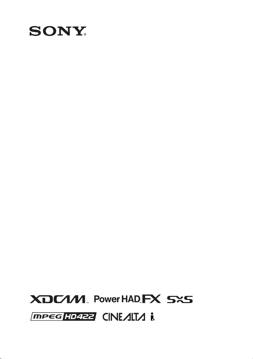
To mount the hard disk unit on the
camcorder
By using the cold shoe kit (an auxiliary shoe, four
screws, and a bottom plate) supplied with the
camcorder, you can mount the hard disk unit on
the accessory fitting shoe of the camcorder.
Foreword / Using an External Hard Disk
3
1 Secure the auxiliary shoe to the
accessory fitting shoe with the four
screws.
Auxiliary shoe
Accessory
fitting shoe
2 Fit the bottom plate (spring type) into
the auxiliary shoe.
Slits for screw holes
Bottom plate
Insert the bottom plate from the end where
the slits for the screw holes of the auxiliary
shoe are not open.
If you secure the auxiliary shoe in the
direction opposite that shown in the above
figure with the slit open end forward, insert
the bottom plate from the direction opposite
to that shown in the figure.
3 Attach the shoe adapter (supplied with
the PHU-120R) to the hard disk unit,
mount the unit to the auxiliary shoe on
the camcorder, and secure it with the
lock lever of the shoe adapter.
For details, refer to the Operating Instructions
of the PHU-120R.
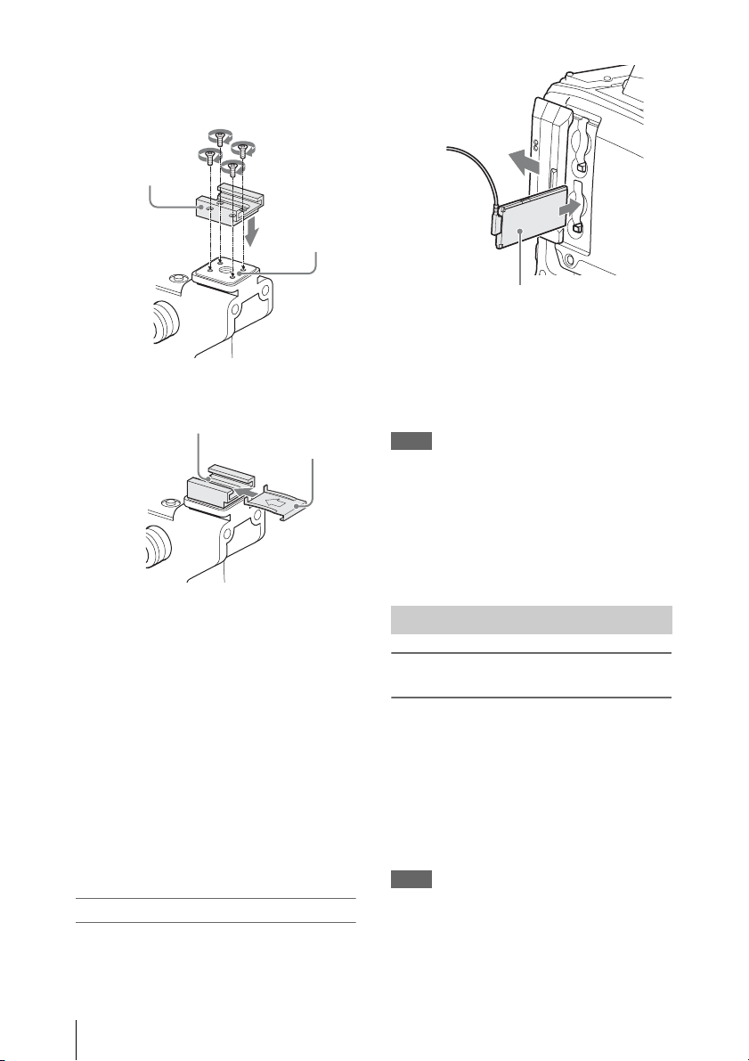
To connect the PHU connection cable
1 Open the cover of the card slot block
and insert the PHU connection cable
into a slot.
Insert so that the cable extends upward.
2 Turn on the PHU-120R.
The POWER indicator of the PHU-120R
lights in green.
Subsequently, the ACCESS lamp of the
camcorder lights in orange then changes to
green once the unit is ready for use.
Notes
• The cover of the card slot block cannot be closed with
the PHU-120R connected.
• Bundle the cable so that i t will not accidentally become
entangled with nearby objects.
To disconnect the PHU connection cable
Operate in the same manner as when you remove
an SxS memory card from the slot.
Formatting the PHU-120R
To format a PHU-120R when you connect
it
When you connect an unformatted PHU-120R, or
connect a PHU-120R that is formatted to different
specifications, or power the camcorder on with an
unformatted PHU-120R connected, or exit mass
storage mode with an unformatted PHU-120R
connected, a message appears on the viewfinder
screen asking if you want to format the device.
If the message appears, turn the MENU knob to
select “Execute”, and then press the knob.
Notes
• The format confirmation message does not appear if
you are currently setting other information.
• The format confirmation mess age may disappear if the
camcorder needs to display other information. It
reappears after the other information has been set.
Using an External Hard Disk
4

To format a PHU-120R from a menu
You can format a PHU-120R by using
OPERATION >Format Media in the setup menu.
This command is available when the PHU-120R
is already formatted, unformatted, and formatted
in an unsupported format.
1 Select OPERATION >Format Media in
the setup menu.
2 Select [Media(A)] (slot A) or [Media(B)]
(slot B).
3 Turn the MENU knob to select
[Execute], and press the knob.
The format confirmation message appears on
the viewfinder screen.
4 Turn the MENU knob to select
“Execute”, and then press the knob.
For information about menu operat ions, refer to
the operation manual of the camcorder.
Formatting begins.
During restoration, an in-progress message
and status bar (%) are displayed, and the
ACCESS lamp lights in orange.
When formatting is completed, a completion
message is displayed for three seconds.
If restoration fails
• A PHU-120R on which an error occurred may
become usable again through repeated
formatting.
• In some cases, some clips cannot be restored.
Playback of clips that can be restored becomes
possible again.
Restoring the PHU-120R
If an error occurs with data on the PHU-120R for
some reason, the hard disk must be restored.
If a PHU-120R that needs to be restored is
connected, a message that prompts you to execute
restoration is displayed on the viewfinder screen.
To restore the hard disk
Turn the MENU knob to select “Execute”, and
then press the knob.
The restoration begins automatically.
During restoration, an in-progress message and
status bar (%) are displayed, and the ACCESS
lamp lights in orange.
When restoration is completed, a completion
message is displayed for three seconds.
Using an External Hard Disk
5

Using a Media Adaptor
FAT
When FAT mode is selected, use of the optional
MEAD-MS01 or MEAD-SD01 Media Adaptor
permits you to insert a “Memory Stick” (with
MEAD-MS01) or an SDHC card (with MEADSD01) to the SxS memory card slot of the
camcorder and use it for recording and playback
in the same way as with an SxS memory card.
Usable “Memory Stick”
“Memory Stick PRO-HG Duo” HXA series
Usable SDHC card
Class 10 SDHC card
For details on use of the MEAD-MS01/SD01 Media
Adaptor, refer to the Operating Instructions of the
adaptor.
Notes
• In UDF mode, no Media Adaptor can be used.
• High-speed playback may not be properly achieved
with a “Memory Stick” or an SDHC card.
• When using the Slow & Quick Motion function with
the “Memory Stick” or an SDHC card, you cannot
perform slow motion shooting.
Formatting
When you use a “Memory Stick” or an SDHC
card with this camcorder, formatting is required.
A “Memory Stick” or an SDHC card to be used
with this camcorder must be formatted using the
format function of this camcorder.
It is also necessary to format a “Memory Stick” or
an SDHC card for use if a caution message is
displayed when you mount the “Memory Stick”
or SDHC card.
For a “Memory Stick” or an SDHC card that was
formatted with another system unsupported by
this camcorder, the message “Unsupported File
System” is displayed on the LCD monitor/EVF
screen.
Format the “Memory Stick” or SDHC card as
instructed below.
To execute formatting
1 Select OPERATION >Format Media in
the setup menu.
2 Select [Media(A)] (slot A) or [Media(B)]
(slot B).
3 Turn the MENU knob to select
[Execute], and press the knob.
The format confirmation message appears on
the viewfinder screen.
4 Turn the MENU knob to select
“Execute”, and then press the knob.
For information about menu operations, refer to
the operation manual of the camcorder.
Formatting begins.
An in-progress message and status bar (%)
are displayed, and the ACCESS lamp lights
in orange. When formatting is completed, a
completion message is displayed for three
seconds.
Note
In formatting, all data in a “Memory Stick” or MEADSD01, including protected images, are erased and cannot
be restored.
Connection between the camcorder and a
computer
To use a “Memory Stick” or MEAD-SD01 in
which data have been recorded with an XDCAM
EX-series product, establish USB connection
between the computer and this camcorder and
insert it into the slot of the camcorder, or use a
specified USB card reader SBAC-US10.
To use a “Memory Stick” formatted with this
camcorder with other devices having a “Memory
Stick” slot
• First make a backup copy of the data recorded
in the “Memory Stick.”
• When the backup is done, format the “Memory
Stick” with the device to be used.
For details on the formatting method, refer to the
Operating Instructions of the device to be used.
To use an SDHC card formatted with this
camcorder with other devices having an SDHC
card slot
• First make a backup copy of the data recorded
in the SDHC card.
Using a Media Adaptor
6
• When the backup is done, format the SDHC
card with the device to be used.
For details on the formatting method, refer to the
Operating Instructions of the device to be used.
• “Memory Stick” and are
trademarks of Sony Corporation.
• “Memory Stick PRO-HG Duo” and
are trademarks of Sony
Corporation.
Operating from the RM-B150/B750
When the RM-B150 or RM-B750 Remote
Control Unit is connected, some camcorder
functions can be controlled from the RM-B150/
B750.
You can use the RM-B750’s display or a video
monitor connected to the MONITOR connector
of the RM-B150/B750 to control the camcorder
by menu operations and monitor the camcorder
picture.
To connect
Using the remote cable (10 m (33 ft)) supplied
with the RM-B150/B750, connect between the
REMOTE connector (8-pin) of the camcorder an d
the camera connector of the RM-B150/B750.
When you turn on the camcorder after the
connection, the camcorder ente rs Remote Control
mode.
Adjusting the Camcorder from the RM-B150/B750
You can control menu and recording operations
from the RM-B150/B750.
For the functions that can be controlled from the
RM-B150/B750, see “Functions That Can Be
Controlled from the RM-B150/B750” on page 11.
Notes
• Remote Control operations cannot be made if USB
connection to the camcorder is enabled.
• Do not connect or disconnect the RM-B150/B750
when the camcorder is on.
The following controls of the camcorder becomes
inoperative when the RM-B150/B750 is
connected.
• GAIN selector
•WHITE BAL switch
• AUTO W/B BAL switch
• SHUTTER selector
• OUTPUT/DCC switch
• Buttons and switches to which the Turbo Gain
function has been assigned, including the
ASSIGN. 1/3 switches, the ASSIGNABLE 4
Operating from the RM-B150/B750
7
switch, the COLOR TEMP. button, and the
ASSIGNABLE 5 switch.
• REC START button: the VTR button on the
lens, and buttons and switches to which the
function has been assigned using OPERATION
>Assignable SW in the setup menu, including
the ASSIGN. 1/3 switches, the ASSIGNABLE
4 switch, the COLOR TEMP. button, and the
ASSIGNABLE 5 switch (when
MAINTENANCE >Camera Config >RM Rec
Start in the setup menu is set to [RM]).
To connect the monitor to the RM-B150/
B750
The MONITOR connector (BNC type) of the
RM-B150/B750 outputs a composite signal. To
connect a m onitor to the MONITO R connector on
the RM-B150/B750, use the black cable supplied
with the RM-B150/B750.
To release Remote Control mode
Turn off the camcorder and disconnect the RMB150/B750.
The settings on the controls on the camcorder
become valid.
Camera image quality adjustment items
when the RM-B150/B750 is connected
When the RM-B150/B750 is connected, the
parameters for camera image quality adjustment
items (paint data) are reset to the parameters that
were specified the last time that RM-B150/B750
was connected.
Relationship between the setting of the RM Rec
Start item and the functi on of recording start/stop
buttons
Recording start/
stop button
Camcorder’s REC
START button
Lens’ VTR button Disabled Enabled Enabled
Buttons and
switches to which
the recording start/
stop function has
been assigned
(ASSIGN. 1/3
switches,
ASSIGNABLE 4
switch, COLOR
TEMP. button, and
ASSIGNABLE 5
switch)
Remote control
unit’s VTR button
Settings of RM Rec Start
RM CAM PARA
Disabled Enabled Enabled
Disabled Enabled Enabled
Enabled Disabled Enabled
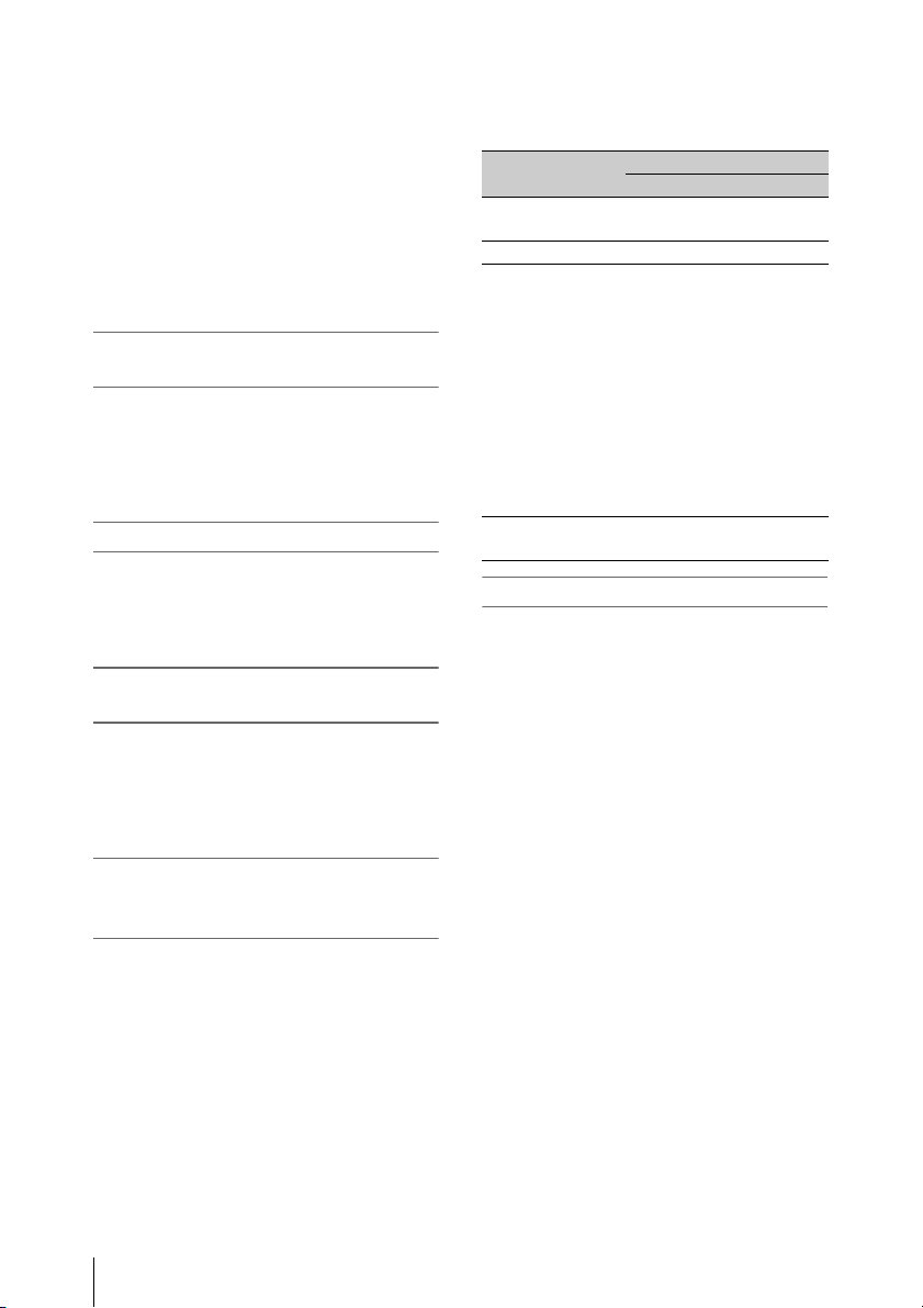
Structure of the paint adjustment data
The non-volatile memory of the camcorder used
for storing paint adjustment data consists of two
regions as shown below: one is the “main data
block” that is used when a remote control unit is
not connected, and the other is the “remote
control data block” that is used when a remote
control unit is connected. Paint adjustment data is
automatically selected and output to the camera
section depending on whether or not a remote
control unit such as the RM-B150 is connected.
Function of the recording start/stop
buttons when the RM-B150/B750 is
connected
When the RM-B150/B750 is connected, you can
make a setting to determine which of the
recording start/stop buttons you will use. This
setting is made using MAINTENANCE >Camera
Config >RM Rec Start in the setup menu.
Operating from the RM-B150/B750
8
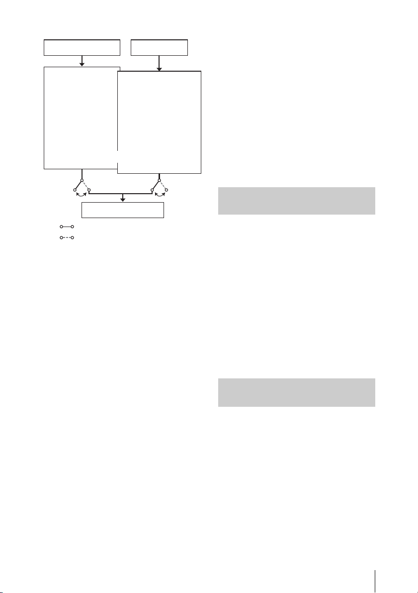
Setup menu of
the camcorder
Main data block
MASTER BLACK
MASTER GAMMA
KNEE POINT
DETAIL LEVEL
R/B GAIN
R/B BLACK
Non-volatile memory
Hardware of the
camera section
RM-B150 connected
RM-B150 not connected
When a remote control unit is connected to the
camcorder, the “remote control data block” is
selected as the current paint data block, and the
paint adjustment parameters that were in effect
the last time the remote control unit was used are
recalled.
The settings of the absolute value rotational
1)
controls
overwritten by those on the remote control unit
after the remote control unit is connected.
When the remote control unit is disconnected
from the camcorder, the “main data block”
becomes effective. Thus the camcorder will
return to the settings that were in effect before the
remote control unit was connected.
1) Absolute value rotational controls: The data
2) Absolute value switches: Like toggle switches or
When MAINTENANCE >Camera Config >RM
Common Memory is set to [On] in the setup
menu, you can use settings of the paint
adjustment data stored in the main data block
even if you connect the remote control unit. In
this case, the settings stored in the main data
block will be renewed when you change the
and absolute value switches2) are
corresponding to the angular position of controls is
output. Rotational controls for which the data
corresponding to the amount of their rotation is output
are called relative value controls.
slide switches (except most momentary switches), the
switches (or knobs) whose positions must coincide
with their functions are called absolute value switches.
RM-B150
Remote control
data block
MASTER BLACK
MASTER GAMMA
KNEE POINT
DETAIL LEVEL
R/B GAIN
R/B BLACK
settings on the remote control unit. Thus, the
settings of the paint data made with the remote
control unit can be retained even if the remote
control unit is removed. However, if the switch
position on the remote control unit differs from
the one on the camcorder, the switch position on
the camcorder takes precedence over that on the
remote control unit.
Also, it is possible to keep the settings that are in
effect before you connect the remote control unit.
In this case, you should set the control knob to the
relative value mode on the remote control unit.
For details, refer to the operation manual supplied
with the remote control unit.
Operating the Menu from the RM-B150
1 Set the DISPLAY switch to MENU.
The camcorder menus can be displayed on a
video monitor connected to the MONITOR
connector of the RM-B150.
2 Select and set the menu items, using the
MENU SELECT knob and the
CANCEL/ENTER switch.
3 When the settings are comp leted, set the
DISPLAY switch to ON or OFF to exit
the menu.
For details on operations of the RM-B150, refer to
the operation manual of the RM-B150.
Operating the Menu from the RM-B750
1 Press and light the MONITOR button
then press the VF MENU button.
The camcorder menus can be displayed on
the RM-B750’s display or a video monitor
connected to t he MONITOR connector of the
RM-B750.
2 Select and set the menu items, using the
MENU SELECT knob, ENTER button,
and CANCEL button.
3 When the settings are completed, press
the VF MENU button to exit the menu.
Operating from the RM-B150/B750
9

For details on operations of the RM-B750, refer to
the operation manual of the RM-B750.
Operating from the RM-B150/B750
10
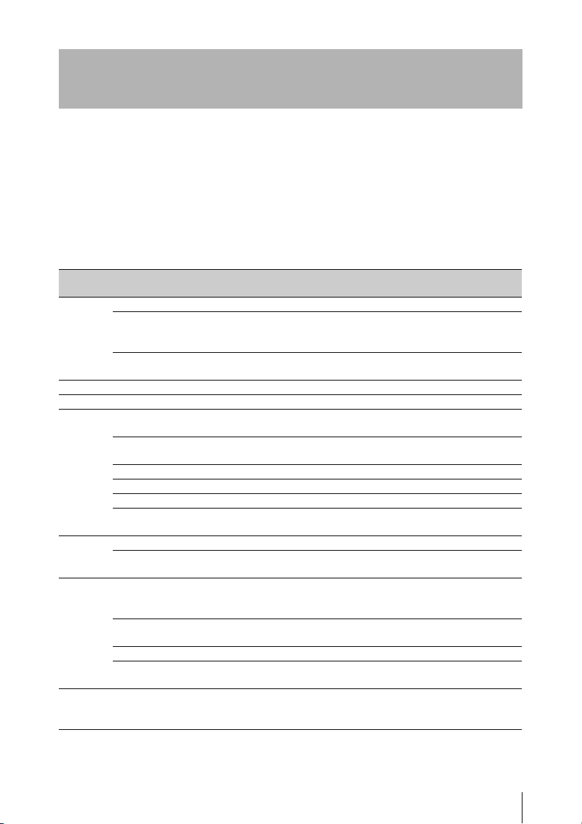
Functions That Can Be Controlled from the RM-B150/ B750
You can adjust the functions in the following table by using menu operations, adjustment knobs, switches,
and the touch panel (RM-B750 only) on the RM-B150/B750.
For details on operations, refer to the operation manual of the RM-B150/B750.
How to Read the Table
The following symbols are used to indicate operations on the RM-B150 and RM-B750.
Switch: A
Touch panel: B
Knob: C
Menu operation: D (Camcorder’s menus can be operated from the RM-B150/B750.)
Menu
items
Gain Step Gain – Sets the master gain. A –
Bars Bars On/Off Turns color bar output on or off. A A
Test Saw Test Saw On/Off Turns the test saw signal on or off. A A
Shutter Step Shutter
DCC DCC On/Off Turns D CC on or off. A B
White
Balance
Black ABB Start/Stop Starts execution of auto black
Sub-item Setting Description RM-B150 RM-B750
a)
L/M/H Low/Mid/High Switches between three gain levels,
Step –3/0/3/6/9/12/18/
Setting
Step Shutter
Speed
ECS Setting On/Off Turns ECS on or off. A B
ECS Frequency – Selects the ECS frequency. C C
SLS Setting On/Off Turns SLS on or off. – B/–
SLS Speed – Sets the SLS speed (number of
DCC Point –99 to ±0 to +99 Adjusts the DCC minimum knee
AWB Start/Stop Starts execution of auto white
White Memory A/B/C/Preset Switches the auto white balance
ATW On/Off Turns ATW on or off. A
5600K On/Off Turns color temperature conversion
24/30/36/42dB
On/Off Turns the step shutter function on or
– Sets the step shutter speed. A B
when the master gain has been set
from a menu.
Sets the master gain. – B
off.
frames).
point.
balance adjustment, or stops
execution.
memory.
on or off.
balance adjustment, or stops
execution.
C+A
AB
–B/–
DC+D
AA
AB
–A+B
AA
–
a)
a)
b)
c)
B
Functions That Can Be Controlled from the RM-B150/B750
11
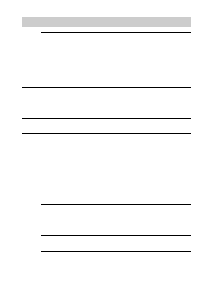
Menu
Sub-item Setting Description RM-B150 RM-B750
items
Iris Iris Mode Auto/Manual Selects the iris mode. A A
Iris Level –99 to ±0 to +99 Adjusts the level of the auto iris
CC
target value.
Close On/Off Turns forcible iris closing on or off. – A
Rec
Function
Slow & Quick On/Off Turns the Slow & Quick Motion
function on or off.
Frame Rate The available
settings vary
depending on the
When the Slow & Quick setting is
On, sets the frame rate for Slow &
Quick Motion shooting.
DB+D
DC+D
Format >HD
System Line
setting.
Camcorder
Menu
Menu On/Off Operates the camcorder menu. – A
Select/Set Select (Up/
–C
Down)/Set
Panel
Active
Panel Active On/Off Enables (On) or disables (Off) panel
operations.
AA
Standard Standard On/Off Selects standard mode. A A
ND Filter ND Filter Display only Turns the display of ND filter
––
settings on or off. (The settings
cannot be changed, only displayed.)
CC Filter CC Filter A/B/C/D Selects a CC filter. A B
Extender
IND
Extender On/Off Turns the lens extender indication
on or off. (The settings cannot be
––
changed, only displayed.)
Call Call On/Off Enables (On) or disables (Off) calls
–A
from externally connected
equipment.
Marker Center Marker On/Off Turns the center marker display on
DD
or off.
User Box On/Off Turns the box cursor display on or
DD
off.
User Box Width –99 to ±0 to +99 Specifies the box cursor width. D D
User Box
–99 to ±0 to +99 Specifies the box cursor height. D D
Height
User Box H
Position
User Box V
Position
–99 to ±0 to +99 Specifies the horizontal position of
the box cursor center.
–99 to ±0 to +99 Specifies the vertical position of the
box cursor center.
DD
DD
Media Rec Start/Stop Starts or stops recording. A A
Play Play/Pause Starts playback. A A
FREV – Starts high-speed reverse playback. A A
FFWD – Starts high-speed playback A A
Stop – Stops playback. A A
Rec Review – Starts a recording review. A A
b)
b)
Functions That Can Be Controlled from the RM-B150/B750
12
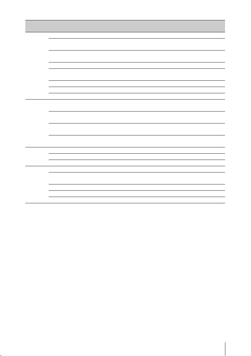
Menu
items
Switch
Status
White R Gain<A> –99 to ±0 to +99 Specifies the white balance R gain
Black Master Black –99 to ±0 to +99 Specifies the master black level. C C
Flare Flare On/Off Turns flare correction on or off. D D
Sub-item Setting Description RM-B150 RM-B750
Gamma On/Off Turns gamma co rrection on or off. D D
Black Gamma On/Off Turns black gamma correction on or
off.
Matrix On/Off Turns linear matrix correction and
user matrix correction on or off.
Knee On/Off Turns knee correction on or off. D D
White Clip On/Off Turns white clip correction on or
off.
Detail On/Off Turns detail correction on or off. D D
Flare On/Off Turns flare correction on or off. D D
Tes t Sa w O n/Off Turns the test saw signal on or off. A A
value saved in memory A.
B Gain<A> –99 to ±0 to +99 Specifies the white balance B gain
value saved in memory A.
R Gain<B> –99 to ±0 to +99 Specifies the white balance R gain
value saved in memory B.
B Gain<B> –99 to ±0 to +99 Specifies the white balance B gain
value saved in memory B.
R Black –99 to ±0 to +99 Specifies the R black level. C C
B Black –99 to ±0 to +99 Specifies the B black level. C C
M Flare –99 to ±0 to +99 Sets the master flare correction
level.
R Flare –99 to ±0 to +99 Sets the R flare correction level. D C
G Flare –99 to ±0 to +99 Sets the G flare correction level. D C
B Flare –99 to ±0 to +99 Sets the B flare correction level. D C
DD
DD
DD
CC
CC
CC
CC
DD
Functions That Can Be Controlled from the RM-B150/B750
13
 Loading...