

Page 1
SOLID-STATE MEMORY CAMCORDER
PMW-500
OPERATION MANUAL [English]
1st Edition (Revised 2)
4260128030
The supplied CD-ROM includes operation manuals for the PMW-500 Solid-State
Memory Camcorder (English, Japanese, French, German, Italian, Spanish and Chinese
versions) in PDF format.
For more details, see “Using the CD-ROM” on page 14.
PMW-500
(SYM)
4-260-128-03 (1)
Sony Corporation
Printed on recycled paper.
Printed in Japan
2011.03 32
© 2010
SOLID-STATE MEMORY CAMCORDER PMW-500
Page 2

WARNING
To reduce the risk of fire or
electric shock, do not
expose this apparatus to
rain or moisture.
To avoid electrical shock,
do not open the cabinet.
Refer servicing to qualified
personnel only.
Important Safety Instructions
• Read these instructions.
• Keep these instructions.
• Heed all warnings.
• Follow all instructions.
• Do not use this apparatus near water.
• Clean only with dry cloth.
• Do not block any ventilation openings.
Install in accordance with the
manufacturer’s instructions.
• Do not install near any heat sources such
as radiators, heat registers, stoves, or
other apparatus (including amplifiers) that
produce heat.
• Do not defeat the safety purpose of the
polarized or grounding-type plug. A
polarized plug has two blades with one
wider than the other. A grounding-type
plug has two blades and a third grounding
prong. The wide blade or the third prong
are provided for your safety. If the
provided plug does not fit into your outlet,
consult an electrician for replacement of
the obsolete outlet.
• Protect the power cord from being walked
on or pinched particularly at plugs,
convenience receptacles, and the point
where they exit from the apparatus.
• Only use attachments/accessories
specified by the manufacturer.
• Refer all servicing to qualified service
personnel. Servicing is required when the
apparatus has been damaged in any way,
such as power-supply cord or plug is
damaged, liquid has been spilled or
objects have fallen into the apparatus, the
apparatus has been exposed to rain or
moisture, does not operate normally, or
has been dropped.
WARNING
Excessive sound pressure from earphones
and headphones can cause hearing loss.
In order to use this product safely, avoid
prolonged listening at excessive sound
pressure levels.
For the customers in the U.S.A.
This equipment has been tested and found
to comply with the limits for a Class B digital
device, pursuant to Part 15 of the FCC
Rules. These limits are designed to provide
reasonable protection against harmful
interference in a residential installation. This
equipment generates, uses, and can radiate
radio frequency energy and, if not installed
and used in accordance with the
instructions, may cause harmful interference
to radio communications. However, there is
no guarantee that interference will not occur
in a particular installation. If this equipment
does cause harmful interference to radio or
television reception, which can be
determined by turning the equipment off and
on, the user is encouraged to try to correct
the interference by one or more of the
following measures:
- Reorient or relocate the receiving
antenna.
- Increase the separation between the
equipment and receiver.
- Connect the equipment into an outlet on a
circuit different from that to which the
receiver is connected.
- Consult the dealer or an experienced
radio/TV technician for help.
You are cautioned that any changes or
modifications not expressly approved in this
manual could void your authority to operate
this equipment.
All interface cables used to connect
peripherals must be shielded in order to
comply with the limits for a digital device
pursuant to Subpart B of Part 15 of FCC
Rules.
If you have any questions about this product,
you may call;
2
Page 3

Sony Customer Information Service Center
1-800-222-7669 or http://www.sony.com/
Declaration of Conformity
Trade Name : SONY
Model : PMW-500
Responsible party : Sony Electronics Inc.
Address : 16530 Via Esprillo,
San Diego, CA
92127 U.S.A.
Telephone Number : 858-942-2230
This device complies with part 15 of the
FCC Rules. Operation is subject to the
following two conditions: (1) this device
may not cause harmful interference, and
(2) this device must accept any
interference received, including
interference that may cause undesired
operation.
For the customers in Canada
This Class B digital apparatus complies with
Canadian ICES-003.
For the customers in Europe
This product with the CE marking complies
with the EMC Directive issued by the
Commission of the European Community.
Compliance with this directive implies
conformity to the following European
standards:
• EN55103-1: Electromagnetic
Interference(Emission)
• EN55103-2: Electromagnetic
Susceptibility(Immunity)
This product is intended for use in the
following Electromagnetic Environments: E1
(residential), E2 (commercial and light
industrial), E3 (urban outdoors), E4
(controlled EMC environment, ex. TV
studio).
The manufacturer of this product is Sony
Corporation, 1-7-1 Konan, Minato-ku,
Tokyo, Japan.
The Authorized Representative for EMC and
product safety is Sony Deutschland GmbH,
Hedelfinger Strasse 61, 70327 Stuttgart,
Germany.
For the State of California, USA only
Perchlorate Material - special handling may
apply, See
www.dtsc.ca.gov/hazardouswaste/
perchlorate
Perchlorate Material : Lithium battery
contains perchlorate.
For the customers in Taiwan only
AVERTISSEMENT
Afin de réduire les risques
d’incendie ou
d’électrocution, ne pas
exposer cet appareil à la
pluie ou à l’humidité.
Afin d’écarter tout risque
d’électrocution, garder le
coffret fermé. Ne confier
l’entretien de l’appareil
qu’à un personnel qualifié.
AVERTISSEMENT
Une pression acoustique excessive en
provenance des écouteurs ou du casque
peut provoquer une baisse de l’acuité
auditive.
Pour utiliser ce produit en toute sécurité,
évitez l’écoute prolongée à des pressions
sonores excessi
Pour les clients au Canada
Cet appareil numérique de la classe B est
conforme à la norme NMB-003 du Canada.
Pour les clients en Europe
Ce produit portant la marque CE est
conforme à la Directive sur la compatibilité
électromagnétique (EMC) émise par la
Commission de la Communauté
européenne.
3
Page 4

La conformité à cette directive implique la
conformité aux normes européennes
suivantes :
• EN55103-1 : Interférences
électromagnétiques (émission)
• EN55103-2 : Sensibilité
électromagnétique (immunité)
Ce produit est prévu pour être utilisé dans
les environnements électromagnétiques
suivants : E1 (résidentiel), E2 (commercial et
industrie légère), E3 (urbain extérieur) et E4
(environnement EMC contrôlé, ex. studio de
télévision).
Le fabricant de ce produit est Sony
Corporation, 1-7-1 Konan, Minato-ku,
Tokyo, Japon.
Le représentant autorisé pour EMC et la
sécurité des produits est Sony Deutschland
GmbH, Hedelfinger Strasse 61, 70327
Stuttgart, Allemagne.
WARNUNG
Um die Gefahr von Bränden
oder elektrischen Schlägen
zu verringern, darf dieses
Gerät nicht Regen oder
Feuchtigkeit ausgesetzt
werden.
Um dieses Produkt sicher zu verwenden,
vermeiden Sie längeres Hören bei sehr
hohen Schalldruckpegeln.
Für Kunden in Europa
Dieses Produkt besitzt die CEKennzeichnung und erfüllt die EMVRichtlinie der EG-Kommission.
Angewandte Normen:
• EN55103-1: Elektromagnetische
Verträglichkeit (Störaussendung)
• EN55103-2: Elektromagnetische
Verträglichkeit (Störfestigkeit)
Für die folgenden elektromagnetischen
Umgebungen: E1 (Wohnbereich), E2
(kommerzieller und in beschränktem Maße
industrieller Bereich), E3 (Stadtbereich im
Freien) und E4 (kontrollierter EMV-Bereich,
z.B. Fernsehstudio).
Der Hersteller dieses Produkts ist Sony
Corporation, 1-7-1 Konan, Minato-ku,
Tokyo, Japan.
Der autorisierte Repräsentant für EMV und
Produktsicherheit ist Sony Deutschland
GmbH, Hedelfinger Strasse 61, 70327
Stuttgart, Deutschland.
Um einen elektrischen
Schlag zu vermeiden, darf
das Gehäuse nicht geöffnet
werden. Überlassen Sie
Wartungsarbeiten stets nur
qualifiziertem
Fachpersonal.
WARNUNG
Zu hoher Schalldruck von Ohrhörern und
Kopfhörern kann Gehörschäden
verursachen.
4
Page 5

Table of Contents
Table of Contents
Foreword .................................................................................................... 11
Before Use....................................................................................... 11
Mode Indications in This Manual ............................................................ 11
Chapter 1 : Overview
Features ...................................................................................................... 12
Using the CD-ROM ................................................................................... 14
Reading the CD-ROM Manuals............................................................... 14
Locations and Functions of Parts and Controls...................................... 15
Power Supply .................................................................................. 15
Accessory Attachments................................................................... 16
Operating and Connectors Section.................................................. 17
LCD Monitor................................................................................... 26
HDVF-20A Viewfinder (Optional)................................................. 28
CBK-VF01 Viewfinder (Optional) ................................................. 29
Status Display on the Viewfinder Screen........................................ 30
Chapter 2 : Preparations
Preparing a Power Supply ........................................................................ 35
Using a Battery Pack....................................................................... 35
Using AC Power ............................................................................. 36
Attaching the Viewfinder .......................................................................... 37
Attaching the Viewfinder................................................................ 37
Adjusting the Viewfinder Position.................................................. 37
Using the BKW-401 Viewfinder Rotation Bracket ........................ 38
Detaching the Eyepiece................................................................... 39
Adjusting the Viewfinder Focus and Screen................................... 39
Setting the Area of Use .............................................................................. 40
Setting the Date/Time of the Internal Clock ........................................... 41
Mounting and Adjusting the Lens............................................................ 42
Adjusting the Flange Focal Length................................................. 42
Preparing the Audio Input System .......................................................... 43
Connecting a Microphone to the MIC IN Connector...................... 43
Connecting Microphones to the AUDIO IN Connectors................ 44
Table of Contents
5
Page 6

Attaching a UHF Portable Tuner (for a UHF Wireless Microphone
System) ..................................................................................... 45
Connecting Line Input Audio Equipment....................................... 47
Tripod Mounting ....................................................................................... 48
Connecting a Video Light ......................................................................... 49
Using the Shoulder Strap .......................................................................... 49
Adjusting the Shoulder Pad Position....................................................... 50
Chapter 3 : Adjustments and Settings
Setting the Video Format .......................................................................... 51
Selecting the Recording Mode........................................................ 53
Changing the Video Format............................................................ 53
Adjusting the Black Balance and the White Balance ............................. 54
Adjusting the Black Balance........................................................... 54
Adjusting the White Balance .......................................................... 55
Setting the Electronic Shutter................................................................... 57
Shutter Modes ................................................................................. 57
Selecting the Shutter Mode and Shutter Speed............................... 57
Changing the Reference Value for Automatic Iris Adjustment............ 59
Adjusting the Audio Level ........................................................................ 60
Manually Adjusting the Audio Levels of the Audio Inputs from the
AUDIO IN CH-1/CH-2 Connectors ......................................... 60
Manually Adjusting the Audio Level of the MIC IN Connector .... 60
Recording Audio on Channels 3 and 4 ........................................... 61
Setting the Time Data................................................................................ 62
Setting the Timecode....................................................................... 62
Setting the User Bits........................................................................ 63
Synchronizing the Timecode........................................................... 63
Setting Shot Data ....................................................................................... 65
Creating a Shot ID........................................................................... 65
Checking Camcorder Settings and Status Information
(Status Screens).................................................................................... 66
Chapter 4 : Shooting
Table of Contents
6
Handling SxS Memory Cards................................................................... 68
About SxS Memory Cards .............................................................. 68
Loading and Ejecting SxS Memory Cards...................................... 69
Selecting the SxS Memory Card to Use.......................................... 70
Page 7

Formatting (Initializing) SxS Memory Cards................................. 70
If You Load a Memory Card Formatted in the Different Recording
Mode from the Mode Selected on the Camcorder.................... 71
Checking the Remaining Recording Time...................................... 71
Restoring SxS Memory Cards......................................................... 72
Handling USB Flash Drives ...................................................................... 73
Formatting (Initializing) USB Flash Drives.................................... 73
Restoring USB Flash Drives ........................................................... 74
Basic Operations........................................................................................ 74
Playing Recorded Clips................................................................... 76
Deleting Recorded Clips ................................................................. 77
Advanced Operations ................................................................................ 77
Recording Shot Marks..................................................................... 77
Setting OK Marks ........................................................................... 78
Starting to Record from Pre-stored Video
(Picture Cache Function) .......................................................... 78
Recording Time-lapse Video (Interval Rec Function).................... 79
Shooting Stop Motion Animations (Frame Rec Function) ............. 81
Shooting with Slow & Quick Motion ............................................. 82
Recording with the Clip Continuous Rec Function ........................ 83
Framing Shots with the Freeze Mix Function................................. 84
Recording Proxy Data ............................................................................... 85
Recording Proxy Data While Recording Clips............................... 85
Recording Proxy Data for Existing Clips........................................ 86
Deleting All Proxy Data from a USB Flash Drive.......................... 86
Planning Metadata Operations ................................................................ 87
Loading a Planning Metadata File into Camcorder’s Internal
Memory..................................................................................... 87
Defining Clip Names in Planning Metadata ................................... 88
Defining Shot Mark Names in Planning Metadata ......................... 90
Chapter 5 : Clip Operations
Clip Playback ............................................................................................. 91
Thumbnail Screen ........................................................................... 91
Playing Clips................................................................................... 94
Using Thumbnails to Search Inside Clips....................................... 95
Thumbnail Operations.............................................................................. 96
THUMBNAIL Menu Configuration............................................... 96
Basic THUMBNAIL Menu Operations.......................................... 98
Changing the Thumbnail Screen Type............................................ 98
Displaying Clip Properties............................................................ 100
Adding and Deleting OK, NG or KP Marks................................. 101
Table of Contents
7
Page 8

Protecting Clips............................................................................. 102
Copying Clips ............................................................................... 102
Deleting Clips................................................................................ 103
Displaying the Expand Thumbnail Screen.................................... 104
Displaying the Essence Mark Thumbnail Screen ......................... 105
Adding and Deleting Shot Marks.................................................. 106
Changing Clip Index Pictures ....................................................... 106
Dividing Clips............................................................................... 106
Chapter 6 : Menu and Detailed Settings
Setup Menu Organization and Levels.................................................... 107
Setup Menu Organization ............................................................. 107
Setup Menu Levels........................................................................ 107
Basic Setup Menu Operations ................................................................ 109
Menu List.................................................................................................. 111
USER Menu (Factory Default Configuration).............................. 111
OPERATION Menu...................................................................... 112
PAINT Menu................................................................................. 129
MAINTENANCE Menu............................................................... 135
FILE Menu.................................................................................... 150
Assigning Functions to Assignable Switches ......................................... 155
Functions That Can Be Assigned to the ASSIGN. 0 Switch ........ 155
Functions That Can Be Assigned to the ASSIGN. 2 Switch ........ 156
Functions That Can Be Assigned to the ASSIGN. 1 and 3 Switches,
the ASSIGNABLE 4 and 5 Switches, and the COLOR TEMP.
Button...................................................................................... 156
Functions That Can Be Assigned to the RET Button on the Lens 159
Chapter 7 : Saving and Loading User Setting Data
Saving and Loading Settings................................................................... 160
Saving Setting Data....................................................................... 160
Loading Setting Data..................................................................... 161
Resetting a File after Changing Its Contents................................. 162
Saving and Loading Scene Files ............................................................. 162
Saving Scene Files ........................................................................ 162
Loading Scene Files...................................................................... 163
Saving and Loading Lens Files............................................................... 164
Setting Lens File Data................................................................... 164
Saving Lens Files.......................................................................... 164
Loading Lens Files........................................................................ 164
Table of Contents
8
Page 9

Loading Lens Files Automatically................................................ 165
Saving and Loading User Files ............................................................... 165
Saving User Files .......................................................................... 165
Loading Setting Data..................................................................... 166
Chapter 8 : Connecting External Devices
Connecting External Monitors ............................................................... 167
Operating Clips with a Computer.......................................................... 169
Using the ExpressCard Slot of a Computer .................................. 169
USB Connection with a Computer................................................ 169
Connecting an External Device (i.LINK Connection).......................... 171
Recording the Camera Picture on an External Device.................. 171
Nonlinear Editing.......................................................................... 172
Recording External Input Signals ................................................. 172
Configuring a Shooting and Recording System.................................... 173
Chapter 9 : Maintenance
Testing the Camcorder............................................................................ 174
Maintenance............................................................................................. 174
Cleaning the Viewfinder ............................................................... 174
Note about the Battery Terminal................................................... 175
Operation Warnings................................................................................ 176
Error Indication............................................................................. 176
Warning Indication........................................................................ 177
Appendix
Important Notes on Operation ............................................................... 184
Exchanging the Battery of the Internal Clock...................................... 186
Specifications............................................................................................ 186
General .......................................................................................... 186
Camera Block................................................................................ 187
Audio Block .................................................................................. 188
Display .......................................................................................... 188
Media Block.................................................................................. 188
Inputs/Outputs............................................................................... 188
Supplied Accessories .................................................................... 189
Recommended Additional Equipment.......................................... 189
Table of Contents
9
Page 10

Chart of Optional Components and Accessories .................................. 191
About i.LINK ........................................................................................... 192
MPEG-4 Visual Patent Portfolio License .............................................. 193
MPEG-2 Video Patent Portfolio License............................................... 193
About Bitmap Fonts ................................................................................ 193
About OpenSSL ....................................................................................... 194
Index.......................................................................................................... 197
Table of Contents
10
Page 11

Foreword
Mode Indications in This Manual
Before Use
After purchasing the PMW-500 Solid-State
Memory Camcorder, before operating, it is
necessary to set the area of use.
(Unless this setting is made, the camcorder will
not operate.)
For details of these settings, see “Setting the Area of
Use” (page 40).
Note
Before attaching/removing optional components or
accessories to/from the PMW-500 (referred to as “the
camcorder”), be sure to turn the power of the camcorder
off.
Some functions and information are available
only when this camcorder is in a specific
operating mode. This manual indicates those
modes by using the following marks. When these
marks appear, the associated function or
information is available only in that mode.
HD
HD mode: When OPERATION >Format >HD/
SD in the setup menu is set to [HD].
UDF
UDF mode: When OPERATION >Format >File
System in the setup menu is set to [UDF].
FAT
FAT mode: When OPERATION >Format >File
System in the setup menu is set to [FAT].
FAT-H D
FAT-HD mode: When OPERATION >Format
>File System in the setup menu is set to [FAT]
and OPERATION >Format >HD/SD in the setup
menu is set to [HD].
FAT-S D
FAT-SD mode: When OPERATION >Format
>File System in the setup menu is set to [FAT]
and OPERATION >Format >HD/SD in the setup
menu is set to [SD].
Foreword / Mode Indications in This Manual
11
Page 12

Chapter 1 Overview
Chapter1 Overview
Features
2
/3-inch full-HD “PowerHAD FX” CCDs
• IT (Interline Transfer) 2/3-inch progressive
image sensors with 207 million pixels, for full
HD resolution (1920 × 1080)
• “PowerHAD FX” CCDs, featuring a signal
processing ASIC with 14-bit A/D converters
These new image sensor technologies enable
the capture of very high-quality images, with
F11 (59.94i) and F12 (50i) sensitivity and an
SN ratio of 59 dB.
1) With noise suppression on (off value is 54 dB) Noise
suppression uses proprietary Sony signal processing
technology to suppress noise in highfrequency
regions.
SxS memory cards as recording media
Using SxS memory cards, the camcorder offers
nonlinear capabilities such as instant random
access and file-based operation.
You can choose FAT or UDF as the file system
for recording media.
1)
For recording in FAT mode, it offers a choice of
bit rates: either 35 Mbps (HQ mode) or 25 Mbps
(SP mode).
For recording in UDF mode, it offers a choice of
bit rates: either 35 Mbps (HQ mode) or 50 Mbps
(HD422 mode).
By utilizing an efficient compression format, the
camcorder records high-quality HD images for
long recording time of approx. 60 minutes at 50
Mbps (HD422 mode) or approx. 90 minutes at 35
Mbps (HQ mode) on a single 32-GB SxS memory
card (when the recording mode is UDF).
It can also record and play two SD formats:
MPEG IMX 50 Mbps and DVCAM 25 Mbps.
1) CBK-MD01 SD Record and Playback Key required.
For details, contact a Sony service representative
1)
Multi-format support
The camcorder supports interlace format
recording (1080/59.94i or 1080/50i), progressive
format recording (1080/29.97P, 1080/23.98P,
720/59.94P, 720/29.97P, 720/23.98P, or 1080/
25P, 720/50P, 720/25P), thus offering the
flexibility needed for worldwide HD recording.
It also supports recording and playback of SD
signals (both NTSC and PAL). The camcorder
has an optional capability to record and play back
SD signals in IMX/DVCAM format, and can
output HD signals down-converted to SD.
Light weight, low power consumption
Design features custom video signal processing
ICs, and SxS memory card recording enable
fanless operation and power consumption of 27
W or less. The camcorder’s light weight (3.4 kg
(7 lb 7.9 oz)) and low center of gravity make it
easy to carry on the shoulder while ensuring
superior stability.
HD recording using the “MPEG-2 Long
GOP” codec and SD recording in MPEG
IMX50/DVCAM format
The camcorder records 1920 × 1080, 1440 ×
1080, and 1280 × 720 HD images using “MPEG2 Long GOP” codec compression.
Features
12
A variety of functions for improved
performance under various shooting
conditions
• Picture Cache function
• Optical ND filters and electrical CC filters
• Hyper gamma
• Slow shutter function
• Clip Continuous Rec function
• Frame Recording function
• Time lapse function (interval recording)
• Slow & quick motion function
• Freeze mix function
• Live & Play function
• Digital extender function
• Focus magnification function
• Assignable switches
1)
Page 13

• 3.5-inch high-resolution color LCD monitor
• Remote control
1) When the optional CBK-HD02 SDI/Composite Input
and 50-pin Interface is installed
Recording data to USB flash drives and
reading data from USB flash drives (UDF
mode)
You can connect USB flash drives to the external
device connector to record proxy data or read
planning metadata. You can also save setup menu
settings to USB flash drives and load menu
settings from USB flash drives into the
camcorder.
Wireless LAN support
You can connect this camcorder to a computer
over a wireless LAN (Wi-Fi connection) by
installing the optional CBK-UPG01 Hardware
Upgrade Key and connecting the optional CBKWA01 Wi-Fi Adapter to the external device
connector.
A Wi-Fi connection allows you to transfer
planning metadata from a computer to this
camcorder, and to transfer clips and other files
from this camcorder to a computer. You can also
use the Live Logging function to transfer proxy
AV data to a computer as you shoot, for logging
of the video currently being shot.
When the CBK-HD02 is installed, you can also
connect the HDCA-702 MPEG TS Adaptor
instead of the camera adaptor. This allows you to
convert this camcorder’s HDSDI output to a
MPEG HD transport stream.
Chapter 1 Overview
Inherits unique features of XDCAM series
The camcorder inherits the workflow features of
the XDCAM series, including thumbnail display
and metadata management, and improves them
by introducing an improved man-machine
interface.
Supports two viewfinder types
Depending on the application, you can use either
the optional HDVF series viewfinder or the CBKVF01 color viewfinder.
Camcorder system configuration
When you install the optional CBK-HD02 SDI/
Composite Input and 50-pin Interface, you can
mount the XDCA-55 HD Camera Adaptor and
connect the XDCU-50 HD Camera Extension
Unit to configure a system for shooting and
recording.
Features
13
Page 14

Chapter 1 Overview
Using the CD-ROM Reading the CD-ROM
Manuals
Two CD-ROMs are supplied with the camcorder.
The CD-ROM labeled “Manuals for Solid-State
Memory Camcorder” contains the PDF files of
OPERATION MANUAL and SUPPLEMENT
for the camcorder (English, Japanese, French,
German, Italian, Spanish and Chinese).
The CD-ROM labeled “Utility Software for
XDCAM” contains application and device driver
software required to access to SxS memory cards
from a computer and to manage material shot
with the camcorder.
Information about how to install the software is
provided in PDF format.
Note
You must install the SxS device driver and SxS UDF
driver software on your computer if it is equipped with
an ExpressCard slot and you want to use it to access SxS
memory cards, if you want to connect the camcorder to
your computer, and if you want to connect an optional
SBAC-US10 SxS Memory Card USB Reader/Writer to
the computer.
Preparations
The following program must be installed on your
computer in order to read the documents
contained on the CD-ROM.
Adobe Reader Version 6.0 or higher
Memo
If Adobe Reader is not installed, you can download it
from the following URL:
http://www.adobe.com/
Adobe and Adobe Reader are trademarks of Adobe
Systems Incorporated in the United States and/or other
countries.
To read the documents
Do the following:
1 Insert the CD-ROM in your CD-ROM
drive.
A cover page appears automatically in your
browser.
If it does not appear automatically in the
browser, double-click on the index.htm file
on the CD-ROM.
2 Select and click on the manual that you
wish to read.
This opens the PDF file.
Memo
The files may not be displayed properly, depending on
the version of Adobe Reader. In such a case, install the
latest version you can download from the URL
mentioned in “Preparations” above.
Note
If you have lost or damaged the CD-ROM, you can
purchase a new one to replace it. Contact a Sony service
representative.
Using the CD-ROM / Reading the CD-ROM Manuals
14
Page 15
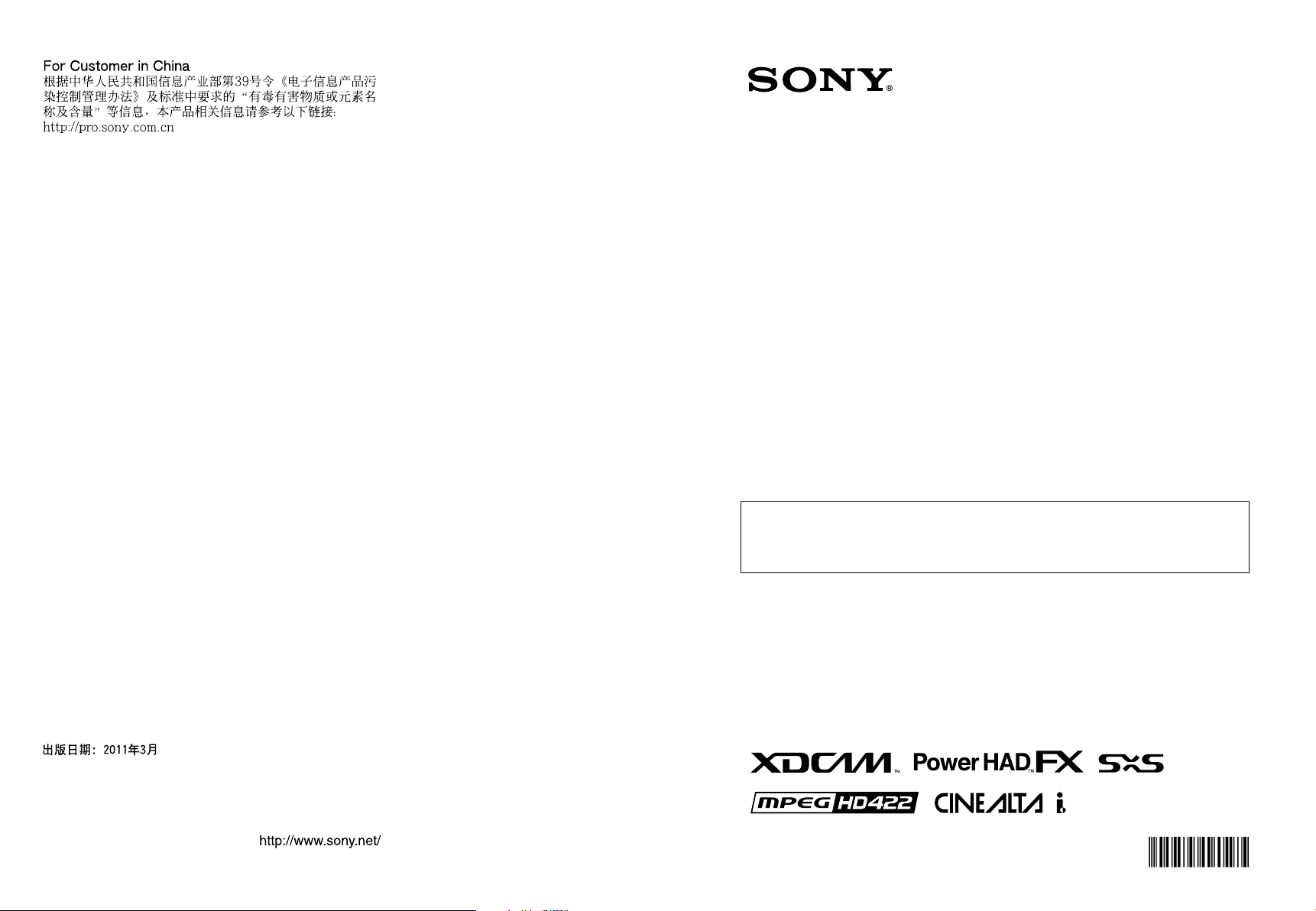
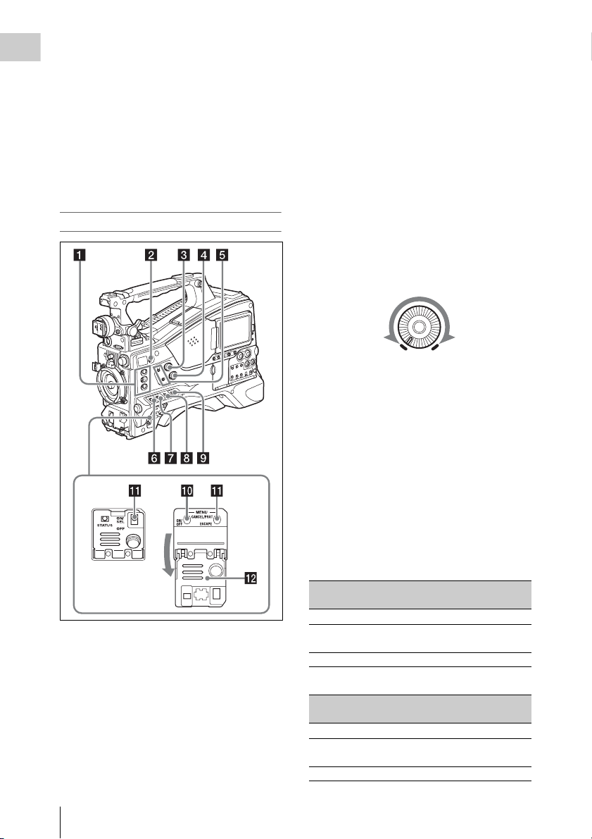
Locations and Functions
)
of Parts and Controls
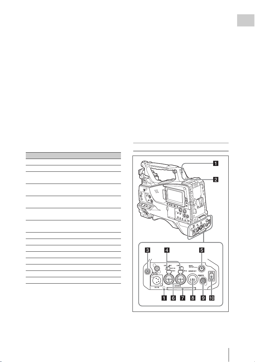
c DC IN (DC power input) connector
(XLR type, 4-pin, male)
To operate the camcorder from an AC power
supply, connect a n optional DC power cord to th is
terminal and then connect the cord to the DC
output terminal of the BC-L70, BC-L160, or
another battery charger.
Chapter 1 Overview
Power Supply
Adaptor connector (see page 15
a LIGHT switch
Determines how a video light connected to the
LIGHT connector (see page 16) is turned on and
off.
AUTO : When the POWER switch of the video
light is in the on position, the video light is
turned on automatically while the camcorder
is recording.
MANUAL: You can turn the video light on or off
manually, using its own switch.
Note
When the camcorder is set for recording in Picture Cache
mode, it is not possible to turn on the light before
operation to start recording is carried out (or while data
is being stored in memory).
d DC OUT 12V (DC power output)
connector (4-pin, female)
Supplies power for an optional WRR-860C/861/
862 UHF Synthesized Diversity Tuner
(maximum 0.5 A).
Note
Do not connect any equipment other than the UHF
synthesized diversity tuner.
e Battery attachment shoe
Attach a BP-GL95/GL65/L80S/L60S Battery
Pack. Alternatively, you can attach an ACDN2B/DN10 AC Adaptor to operate the
camcorder on AC power supply.
For details, see “Preparing a Power Supply”
(page 35).
For details, see “Attaching a UHF Portable Tuner
(for a UHF Wireless Microphone System)”
(page 45).
Note
For your safety, and to ensure proper operation of the
camcorder, Sony recommends the use of the following
battery packs: BP-GL95, BP-GL65, BP-L60S, and
BP-L80S.
Adaptor connector
Enables connection of an XDCA-55 HD Camera
Adaptor or an HDCA-702 MPEG TS Adaptor. To
connect an adaptor, remove the cover from the
connector and install the optional CBK-HD02
SDI/COMPOSITE Input and 50 Pin Interface.
b POWER switch
Turns the main power supply on and off.
Locations and Functions of Parts and Controls
15
Page 16
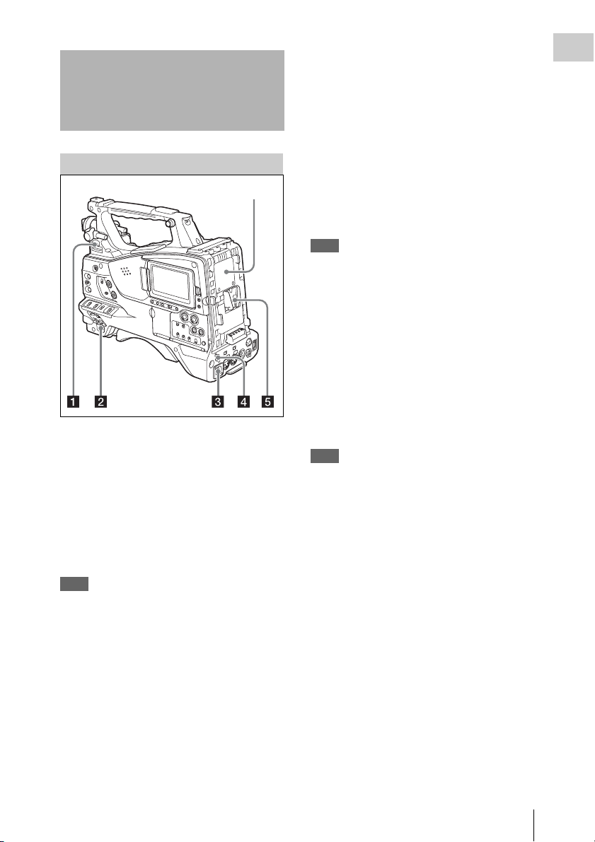
Accessory Attachments
Chapter 1 Overview
a Shoulder strap fitting
Attach the supplied shoulder strap (see page 49).
b Accessory fitting shoe
Attach an optional accessory such as a video light
(see page 49).
c Viewfinder front-to-back positioning
lever
To adjust the viewfinder position in the front-toback direction, loosen this lever and the LOCK
knob. After adjustment, retighten this lever and
the LOCK knob.
d Viewfinder left-to-right positioning ring
Loosen this ring to adjust the left-to-right position
of the viewfinder (see page 37).
e Viewfinder fitting shoe
Attach the viewfinder.
f VF (viewfinder) connectors (26-pin,
rectangular and 20-pin, round)
The analog interface connector (20-pin) is for
connection of an HDVF series viewfinder, and
the digital interface connector (26-pin) is for
connection of an HD viewfinder CBK-VF01.
Use a connection cable to connect your
viewfinder to the corresponding connector.
Note
Do not connect viewfinders to both connectors at the
same time.
g Lens mount securing rubber
After locking the lens in position using the lens
locking lever, fit this rubber over the lower of the
two projections. This fixes the lens mount,
preventing it from coming loose.
h Viewfinder front-to-back positioning
knob (LOCK knob)
Loosen this knob to adjust the front-to-back
position of the viewfinder (see page 37).
i Fitting for optional microphone holder
Fit an optional CAC-12 Microphone Holder (see
page 44).
j Shoulder pad
Raise the shoulder pad fixing lever to adjust the
position in the front-to-rear direction. Adjust the
position for maximum convenience when
operating the camcorder on your shoulder (see
page 50).
k LIGHT (video light) connector (2-pin,
female)
A video light with a maximum power
consumption of 50 W, such as the Anton Bauer
Ultralight 2 or equivalent can be connected (see
page 49).
l Lens cable clamp
Clamp a lens cable.
m MIC IN (microphone input) (+48 V)
connector (XLR type, 5-pin, female)
Connect a stereo microphone to this connector.
The power (+48 V) is supplied via this connector.
n LENS connector (12-pin)
Connect a lens cable to this connector.
Note
When connecting or disconnecting the lens cable to this
connector, power off the camcorder first.
o Tripod mount
When using the camcorder on a tripod, attach the
tripod adaptor (optional).
Locations and Functions of Parts and Controls
16
Page 17
p Lens mount (special bayonet mount)
Attach the lens.
Consult a Sony service representative for
information about available lenses.
q Lens locking lever
After inserting the lens in the lens mount, rotate
the lens mount ring with this lever to lock the lens
in position.
After locking the lens, be sure to use the lens
mount securing rubber to prevent the lens from
becoming detached.
r Lens mount cap
Remove by pushing up the lens locking lever.
When no lens is mounted, keep this cap fitted for
protection from dust.
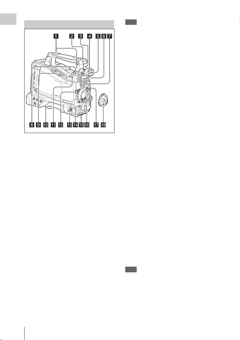
Operating and Connectors Section
Front
For details, see “Setting the Electronic Shutter”
(page 57).
c FILTER selector
Switches between four ND filters built into this
camcorder.
When this selector is used, the new setting
appears on the viewfinder screen for about three
seconds.
FILTER selector
setting
1CLEAR
2
3
4
ND filter
1
/4 ND (attenuates light to
approximately
1
/16 ND (attenuates light to
approximately
1
/64 ND (attenuates light to
approximately
1
/4)
1
/16)
1
/64)
You can change a MAINTENANCE menu
setting so that different white balance settings can
be stored for different FILTER selector positions.
This allows you to automatically obtain optimum
white balance for the current shooting conditions
in linkage with the filter selection.
For details, see “Adjusting the White Balance”
(page 55).
d MENU knob
Changes the item selection or a setting within the
menu (see page 109).
Chapter 1 Overview
a REC START (recording start) button
Press to start recording. Press it again to stop
recording. The effect is the same as that of the
REC button on the lens.
b SHUTTER selector
Set to ON to use the electronic shutter. Push to
SELECT to switch the shutter speed or shutter
mode setting. When this switch is operated, the
new setting appears on the viewfinder screen for
about three seconds.
e AUTO W/B BAL (automatic white/
black balance adjustment) switch
Activates the automatic white/black balance
adjustment functions.
WHITE: Adjust the white balance automatically.
If the WHITE BAL switch (see page 19) is
set to A or B, the white balance setting is
stored in the corresponding memory. If the
WHITE BAL switch is set to PRST, the
automatic white balance adjustment function
does not operate.
BLACK: Adjust the black set and black balance
automatically.
You can use the AUTO W/B BAL switch even
when the ATW (Auto Tracing White Balance)
function is operating.
If you push the switch to the WHITE side once
more during the automatic white balance
adjustment, the adjustment is cancelled and the
Locations and Functions of Parts and Controls
17
Page 18
white balance setting returns to the original
setting.
Chapter 1 Overview
If you push the switch to the BLACK side once
more during the automatic black balance
adjustment, the adjustment is cancelled and the
black balance setting returns to the original
setting.
f MIC (microphone) LEVEL control
Adjusts the input level of audio channels 1, 2, 3
and 4 (see page 60).
Right side (near the front)
b COLOR TEMP. (color temperature)
button
Press to light the button and change the color
temperature for shooting (factory default setting).
You can use this as an assignable switch (see
page 155).
c ALARM (alarm tone volume
adjustment) knob
Controls the volume of the warning tone that is
output via the built-in speaker or optional
earphones. When the knob is turned to the
minimum position, no sound can be heard.
However, if MAINTENANCE >Audio >Min
Alarm Volume in the setup menu is set to [Set],
the alarm tone is audible even when this volume
control is at the minimum position.
ALARM
Minimum Maximum
d MONITOR (monitor volume
adjustment) knob
Controls the volume of the sound other than the
warning tone that is output via the built-in speaker
or earphones. When the knob is turned to the
minimum position, no sound can be heard.
a ASSIGN. (assignable) 1/2/3 switches
You can assign the desired functions to these
switches on OPERATION >Assignable SW in
the setup menu (see page 155).
Off is assigned to the ASSIGN 1/2/3 switches as
the factory default setting.
The ASSIGN.1/3 switches are provided with an
indicator to show whether a function is assigned
to the switch (ON) or not (OFF).
Locations and Functions of Parts and Controls
18
e MONITOR (audio monitor selection)
switches
By means of combinations of the two switches,
you can select audio that you want to hear through
the built-in speaker or earphones.
Position of down-side switch: CH-1/2
Position of up-side
switch
CH-1/CH-3 Channel 1 audio
MIX Channels 1 and 2 mixed
CH-2/CH-4 Channel 2 audio
Audio output
audio (stereo)
a)
Position of down-side switch: CH-3/4
Position of up-side
switch
CH-1/CH-3 Channel 3 audio
MIX Channels 3 and 4 mixed
CH-2/CH-4 Channel 4 audio
Audio output
audio (stereo)
a)
Page 19

a) By connecting stereo headphones to the EARPHONE
jack, you can hear the audio in stereo. (Under
MAINTENANCE >Audio in the setup menu,
Headphone Out must be set to STEREO.)
f ASSIGN. (assignable) 0 switch
You can assign the desired function to this switch
on OPERATION >Assignable SW in the setup
menu (see page 156).
Off is assigned to this switch when the camcorder
is shipped from the factory.
This is a momentary type switch. Each press of
the switch turns the function assigned to this
switch on or off.
g GAIN selector
Switches the gain of the video amplifier to match
the lighting condition s during shooting. The gains
corresponding to the L, M, and H settings can be
selected on OPERATION >Gain Switch in the
setup menu (see page 119). (The factory settings
are L=0 dB, M=6 dB, and H=12 dB.)
When this switch is adjusted, the new setting
appears on the viewfinder screen for about three
seconds.
h OUTPUT/DCC (output signal/dynamic
contrast control) switch
Switches the video signal output from the camera
module, between the following two.
BARS: Output the color bar signal.
CAM: Output the video signal being shot. When
this is selected, you can switch DCC
1)
on and
off.
1) DCC (Dynamic Contrast Control): Against a very
bright background with the iris opening adjusted to the
subject, objects in the background will be lost in the
glare. The DCC function will suppress the high
intensity and restore much of the lost detail and is
particularly effective in the following cases.
• Shooting people in the shade on a sunny day
• Shooting a subject indoors, against a background
through a window
• Any high contrast scene
i WHITE BAL (white balance memory)
switch
Controls adjustment of the white balance.
PRST: Adjust the color temperature to the preset
value (the factory default setting: 3200K).
Use this setting when you have no time to
adjust the white balance.
A or B: Recall the white balance adjustment
settings already stored in A or B. Push the
AUTO W/B BAL switch (see page 17) on
the WHITE side, to automatically adjust the
white balance, and save the adjustment
settings in memory A or memory B.
1)
B (ATW
): When this switch is set to B and
OPERATION >White Setting >White
Switch<B> is set to [ATW] in the setup
menu, ATW is activated.
You can use the AUTO W/B BAL switch
even when ATW is in use.
When this switch is adjusted, the new setting
appears on the viewfinder screen for about three
seconds.
1) ATW (Auto Tracing White Balance): The white
balance of the picture being shot is adjusted
automatically for varying lighting conditions.
j MENU ON/OFF switch
To use this switch, open the cover.
This switch is used to display the menu on the
viewfinder screen or the test signal screen. Each
time the switch is pushed down, the menu screen
is turned on and off.
The function of this switch is the same as that of
the MENU button in the thumbnail screen
operations section.
Note
This switch has different functions depending on
whether or not a menu is displayed.
k MENU CANCEL/PRST (preset) /
ESCAPE switch
To use the MENU CANCEL/PRST/ESCAPE
switch, open the cover.
Note
It is not possible to turn off the menu screen by closing
the cover.
Use the switch in the following way when the
menu is not displayed.
CANCEL/PRST: Each time this switch is
pushed upward, a window to confirm the
menu settings and status of the camcorder
appears on the viewfinder screen (see
page 66). The window consists of five pages,
which are switched each time the switch is
pushed upward. Each page is displayed for
about 10 seconds.
ESCAPE: To clear the page immediately after
display, push this switch down to the OFF
position.
Chapter 1 Overview
Locations and Functions of Parts and Controls
19
Page 20
Use the switch in the following way when the
menu is displayed.
Chapter 1 Overview
CANCEL/PRST: Pushing this switch up to this
position after a setting is changed in the setup
menu displays the message to confirm
whether the previous settings are cancelled.
Pushing this switch up to this position again
cancels the previous settings.
Pushing this switch up to this position before
a setting is changed in the setup menu or after
a setting change is cancelled in the setup
menu displays the message to confirm
whether the setting is reset to the initial
value.
Pushing this switch up to this position again
resets the settings to the initial value.
ESCAPE: Use this switch when the menu page,
which has a hierarchical structure, is opened.
Each time the switch is pushed to this
position, the page returns to one stage higher
in the hierarchy.
l Cover
Open this cover to use the MENU ON/OFF
switch or the MENU CANCEL/PRST/ESCAPE
switch.
Right side (near the rear)
Locations and Functions of Parts and Controls
20
a Built-in speaker
The speaker can be used to monitor E-E1) sound
during recording, and playback sound during
playback. The speaker also sounds alarms to
reinforce visual warnings (see page 176).
If you connect earphones to the EARPHONE
jack, the speaker output is suppressed
automatically.
1) E-E: Abbreviation of “Electric-to-Electric”. In E-E
mode, video and audio signals input to the camcorder
are output after passing through internal electric
circuits only. This can be used to check input signals.
b LCD monitor
Displays remaining battery capacity, remaining
media capacity, audio levels, time data, and so on
(see page 26).
Also allows you to check camera and playback
pictures.
Page 21

You can adjust the position and angle of the LCD
monitor.
c WARNING indicator
Lights up or flashes when an abnormality occurs
(see page 176).
d ACCESS lamp
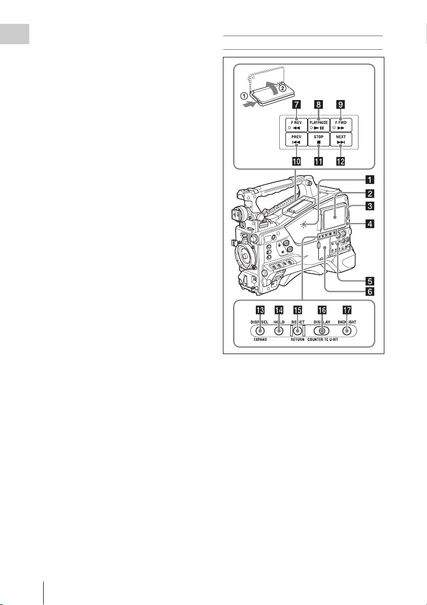
Lights up in blue when data is written to or read
from the recording media.
i F FWD (fast forward) button and
indicator
This plays back at high speed in the forward
direction. The playback speed changes in the
order ×4 t ×15 t ×24 with each press of the
button. The indicator lights during high-speed
playback in the forward direction.
j PREV button
This jumps to the first frame of the current clip.
If you press this together with the F REV button,
the jump is to the first frame of the first recorded
clip on the recording media.
If you press this button twice in rapid succession,
the jump is to the first frame of the last preceding
clip (or the first frame of the current clip when no
preceding clips exist).
k STOP button
Press this button to stop playback.
Chapter 1 Overview
e Protection cover of the audio control
section
Open to access the audio control section (see
page 22).
f Protection cover of the thumbnail
screen operations section
Open to access the thumbnail screen operations
section (see page 22).
g F REV (fast reverse) button and
indicator
This plays back at high speed in the reverse
direction. The playback speed changes in the
order ×4 t ×15 t ×24 with each press of the
button. The indicator lights during high-speed
playback in the reverse direction.
h PLAY/PAUSE button and indicator
Press this button to view play back video images
using the viewfinder screen or the LCD monitor.
The indicator lights during playback.
Press this button again during playback to pause,
outputting a still image. At this time the indicator
flashes at a rate of once per second.
Pressing the F REV or F FWD button during
playback or pause starts high speed playback in
the forward or reverse direction.
l NEXT button
This jumps to the first frame of the next clip.
If you press this together with the F FWD button,
the jump is to the first frame of the last recorded
clip on the recording media.
m DISP SEL (display selection)/EXPAND
(expand function) button
With each press of this button, the display in the
LCD monitor changes as follows.
Display indication Meaning
Video with
superimposed
information (CHAR)
Video without
superimposed
information (MONI)
Status display
(STATUS)
If you press this button when the thumbnail
screen is displayed, the duration of the selected
clip is divided into fractions, and the first frame of
each of the divisions is shown in a further
thumbnail display (expand function). For an HD
recorded MP4 clip, its duration is divided into 12.
If an SD recorded AVI clip comprises multiple
files, the divisions are displayed for the individual
files.
The LCD monitor displays
the same text information as
the viewfinder.
The video only appears.
Counter indications,
warnings, audio levels, and
similar information appear.
No video image appears.
Locations and Functions of Parts and Controls
21
Page 22
For MP4 clips, each tim e you press this button the
division is repeated. Hold down the SHIFT button
Chapter 1 Overview
and press this button to step back through the
division process.
n HOLD (display hold) button
Pressing this button instantly freezes the time data
displayed in the LCD monitor. (The timecode
generator continues runni ng.) Pressing this button
again releases the hold.
For details of the counter display, see page 27.
o RESET/RETURN button
Resets the value shown in the time counter
display in the LCD monitor. According to the
settings of the PRESET/REGEN/CLOCK switch
(see page 23) and the F-RUN/SET/R-RUN
switch (see page 23), this button resets the
display as follows.
Settings of switches To r e s e t
DISPLAY switch: COUNTER Counter to
DISPLAY switch: TC
PRESET/REGEN/CLOCK
switch: PRESET
F-RUN/SET/R-RUN switch:
SET
DISPLAY switch: U-BIT
PRESET/REGEN/CLOCK
switch: PRESET
F-RUN/SET/R-RUN switch:
SET
a) Of the timecode bits for every frame recorded on the
media, those bits which can be used to record useful
information for the user such as scene number,
shooting place, etc.
For details, see “Setting the Time Data” (page 62).
0:00:00:00
Timecode to
00:00:00:00
User bits data
00 00 00 00
This button returns to the previous screen when
pressed during thumbnail screen display, expand
thumbnail screen display, or essence mark
thumbnail screen display.
p DISPLAY switch
This cycles the data displayed in the time counter
display in the LCD monitor through the sequence
COUNTER, TC, and U-BIT (see page 27).
COUNTER: Display the elapsed recording/
playback time (hours, minutes, seconds,
frames).
TC: Display timecode.
U-BIT: Display user bits data.
q BRIGHT (brightness) button
Switches the brightness of the LCD monitor
backlight.
Each press of the button selects the next setting in
the order shown in the following table.
If you press the button with the LCD monitor off,
the LCD backlight comes on in the H state.
Setting LCD monitor backlight
H High (select this to view the LCD
monitor outdoors in the daytime)
M Brightness between H and L
L Low (select this to view the LCD monitor
indoors or outdoors at night)
OFF Off (the display is also off)
Thumbnail screen operations section and audio
control section
a)
to
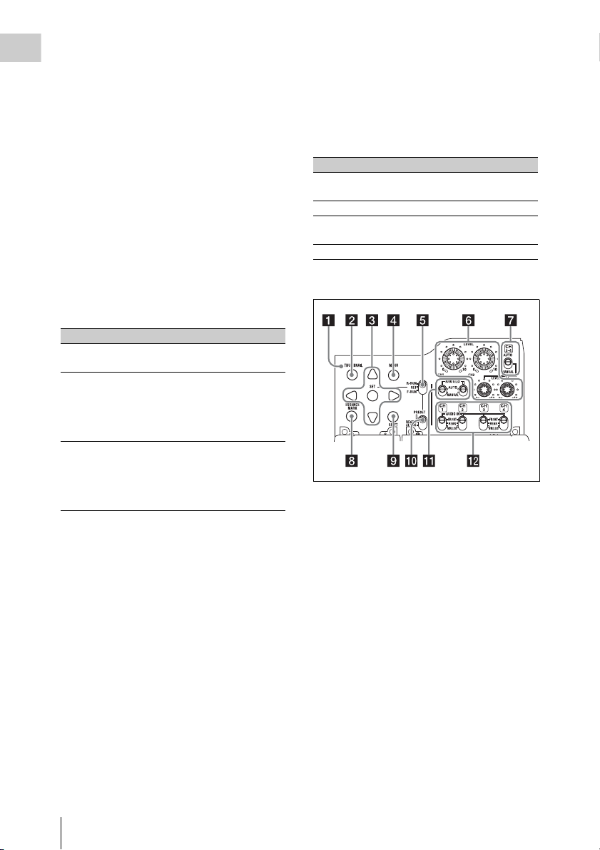
a THUMBNAIL indicator
This lights when thumbnail screen is displayed.
b THUMBNAIL button
Press this button to display the thumbnail screen
(see page 91) and to carry out a thumbnail
operation.
Press once more to return to the original display.
c SET (set) button and arrow buttons
Use these buttons to make timecode and user bit
settings, and for thumbnail screen operations (see
page 98).
When the menu is displayed, press this button to
select an item or to confirm the setting change.
d MENU button
Each press of this button turns the setup menu
display on and off.
The function of this button is the same as that of
the MENU ON/OFF switch.
Locations and Functions of Parts and Controls
22
Page 23

e F-RUN/SET/R-RUN (free run/set/
recording run) switch
Selects the operating mode of the internal
timecode generator. The operating mode is set as
explained below, depending on the position of the
switch.
F-RUN: Timecode keeps advancing, regardless
of whether the camcorder is recording. Use
this setting when synch ronizing the timecode
with external timecode.
SET: Sets the timecode or user bits.
R-RUN: Timecode advances only during
recording. Use this setting to have a
consecutive timecode on the recording
media.
For details, see “Setting the Timecode” (page 62)
and “Setting the User Bits” (page 63).
f LEVEL CH1/CH2/CH3/CH4 (audio
channel 1/2/3/4 recording level) knobs
Adjust the audio levels to be recorded on channels
1, 2, 3, and 4 when the AUDIO SELECT CH1/
CH2 and AUDIO SELECT CH 3-4 switches are
set to MANUAL.
g AUDIO SELECT CH 3-4 (audio
channel 3/4 adjustment method
selection) switch
Select the audio level adjustment method for each
of audio channels 3 and 4.
AUTO : Automatic adjustment
MANUAL: Manual adjustment
h ESSENCE MARK button
By pressing this button when a thumbnail display
is on the screen, you can view the following
thumbnail displays of the essence-marked frames
of the selected clip, depending on the item
selected in a list displayed on the screen.
All: Thumbnail display of all frames marked with
essence marks.
Rec Start (in UDF mode): Thumbnail display of
frames marked with Rec Start marks and of
the first frames o f clips (when the first frames
are not marked with Rec Start marks).
Shot Mark1: Thumbnail display of the frames
marked with Shot Mark 1
Shot Mark2: Thumbnail display of the frames
marked with Shot Mark 2
You can also select Shot Mark 0 and Shot Mark 3
to Shot Mark 9.
If you have recorded clips by using planning
metadata that defined names for Shot Mark 0 to
Shot Mark 9, the defined names are displayed
instead of the above item names in the list.
i SHIFT button
Use this in combination with other buttons.
j PRESET/REGEN (regeneration)/
CLOCK switch
Selects the type of timecode to record.
PRESET: Record new timecode on the media.
REGEN: Record timecode continuous with the
existing timecode recorded on the media.
Regardless of the setting of the F-RUN/SET/
R-RUN switch, the camcorder operates in RRUN mode.
CLOCK: Record timecode synchronized to the
internal clock. Regardless of the setting of
the F-RUN/SET/R-RUN switch, the
camcorder operates in F-RUN mode.
k AUDIO SELECT CH1/CH2 (audio
channel 1/2 adjustment method
selection) switches
Select the audio level adjustment method for each
of audio channels 1 and 2.
AUT O: Automatic adjustment
MANUAL: Manual adjustment
l AUDIO IN CH1/CH2/CH3/CH4 (audio
channel 1/2/3/4 input selection) switches
Select the audio input signals to be recorded on
audio channels 1, 2, 3 and 4.
FRONT: Audio input signals from the
microphone connected to the MIC IN
connector
REAR: Audio input signals from an audio device
connected to the AUDIO IN CH-1/CH-2
connectors
WIRELESS: Audio input signals from the UHF
portable tuner if it is installed
Chapter 1 Overview
Locations and Functions of Parts and Controls
23
Page 24
Left side and upper section
Chapter 1 Overview
b PC connector
Used to put this camcorder into USB connection
mode and use it as an external storage device for
a computer. When a computer without
ExpressCard slot is connected to this connector,
every memory card inserted in the camcorder is
recognized as a drive for that computer.
c External device connector
Connect an optional CBK-WA01 Wi-Fi Adapter
or a USB flash drive.
When a CBK-WA01 is connected: Wireless
LAN connection is available.
When a USB flash drive is connected:
Recording, saving and loading the following
data are available.
• Recording of proxy data (see page 85)
• Loading of planning metadata (see
page 87)
• Save and load setting data (see page 160)
Notes
• When you connect a CBK-WA01, install the optional
CBK-UPG01 Hardware Upgrade Key.
• Use this connector only for connecting a CBK-WA01
or a USB flash drive. Do not connect and use a USB
hub or similar products.
For details on how to use t he CBK-WA01, refer to the
Supplement supplied in the CD-ROM (labeled
“Manuals for Solid-State Memory Camcorder”).
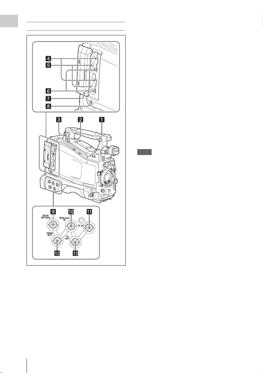
a ASSIGNABLE 4/5 switches
You can assign the desired functions to these
switches on OPERATION >Assignable SW in
the setup menu (see page 156).
Off is assigned to these switches when the
camcorder is shipped from the factory.
Locations and Functions of Parts and Controls
24
d SxS memory card slots
These two slots (A and B) can receive SxS
memory cards or other recording media (see
page 69).
e ACCESS lamps
Indicate the state of slots A and B (see page 69).
You can check whether the lamps are lit even
when the slot cover is closed.
f EJECT buttons
To remove the recording media from the slot,
press the EJECT button to release the lock, then
press the button once more. This makes the media
come out of the slot partially (see page 70).
g Slot cover
Slide to the left and right to open and close.
Page 25
h SLOT SELECT (SxS memory card
select) button
When SxS memory cards are loaded in both card
slots A and B, press this button to select the card
you want to use (see page 70).
i SDI IN (OPTION) (SDI input
(optional)) connector (BNC type)
When the optional CBK-HD02 SDI/
COMPOSITE Input and 50 Pin Interface is
installed, the camcorder can record HDSDI or
SDSDI signals input to this connector.
j GENLOCK IN (genlock signal input)
connector (BNC type)
This connector inputs a reference signal when the
camcorder is to be genlocked or when timecode is
to be synchronized with external equipment.
Available refer ence signals vary depending on the
current system frequency as shown in the
following table.
System frequency Available reference signals
1080/59.94i 1080/59.94i, 480/59.94i
1080/29.97P 1080/59.94i, 480/59.94i
1080/23.98P (PsF
output)
1080/23.98P
(Pulldown output)
720/59.94P 1080/59.94i, 720/59.94P,
720/29.97P 1080/59.94i, 720/59.94P,
720/23.98P 1080/59.94i, 720/59.94P,
480/59.94i 1080/59.94i, 480/59.94i
480/29.97P 1080/59.94i, 480/59.94i
1080/50i 1080/50i, 576/50i
1080/25P 1080/50i, 576/50i
720/50P 1080/50i, 720/50P, 576/50i
720/25P 1080/50i, 720/50P, 576/50i
576/50i 1080/50i, 576/50i
576/25P 1080/50i, 576/50i
1080/23.98PsF, 480/59.94i
1080/59.94i, 480/59.94i
480/59.94i
480/59.94i
480/59.94i
(Genlock for the camera module supports
horizontal sync signals only.) Use
MAINTENANCE >GENLOCK in the setup
menu to adjust the genlock H-phase (phase of
horizontal sync signal).
When the optional CBK-HD02 SDI/
COMPOSITE Input and 50 Pin Interface is
installed, the camcorder can record analog
composite video signals input to this connector.
k TC IN (timecode input) connector
(BNC type)
To apply an external lock to the timecode of the
camcorder, input the reference timecode.
For details, see “Setting the Timecode” (page 62).
l VIDEO OUT connector (BNC type)
Outputs video signals for monitoring. The output
signals can be selected either composite video or
HD-Y depending on the setting of OPERATION
>Input/Output >Output&i.LINK in the setup
menu.
m TC OUT (timecode output) connector
(BNC type)
To lock the timecode of an external VTR to the
timecode of this camcorder, connect this
connector to the external VTR’s timecode input
connector.
Rear
Chapter 1 Overview
Locations and Functions of Parts and Controls
25
Page 26
a TALLY (back tally) indicators (red)
Light up during recording. They will not light if
Chapter 1 Overview
the TALLY switch is set to OFF. These indicators
also flash to indicate warnings (see page 21). The
tally indicator on the front of the viewfinder and
the REC indication on the viewfinder screen light
or flash in the same manner.
For details, see “Operation Warnings” (page 176).
b TALLY switch
Set to ON to activate the TALLY indicator
function.
c EARPHONE jack (stereo, minijack)
You can monitor the E-E sound during recording
and playback sound during playback. When an
alarm is indicated, you can hear the alarm sound
through the earphone. Plugging an earphone into
the jack automatically cuts off the built-in
speaker.
You can select monaural or stereo on
MAINTENANCE >Audio in the setup menu.
d AUDIO IN selectors
Select the audio source you connect to the
AUDIO IN CH1/CH2 connectors.
LINE: When connecting a stereo amplifier or
other external audio signal source
MIC: When connecting a microphone that does
not require 48 V power supply
+48V: When connecting a microphone that
requires 48 V power supply
e HD/SD SDI OUT connector (BNC type)
Outputs an HDSDI or SDSDI signal (with
embedded audio). The output from this connector
can be turned on or off by OPERATION >Input/
Output >SDI Output in the setup menu.
By loosening the screws which retain the cover to
the bottom of the camcorder, you can adjust the
position of the cover depending on the size and
shape of the microphone or audio cable plugs.
After adjusting the position, tighten the screws to
secure the cover.
h AUDIO OUT connector (XLR type, 5-
pin, male)
Outputs the audio signals recorded on audio
channels 1 and 2 or audio channels 3 and 4. The
audio signals are selected by the MONITOR
switch.
i REMOTE connector (8-pin)
Connect a remote control unit, which makes it
possible to control the camcorder remotely.
Note
Before connecting/disconnecting the Remote Control
Unit to/from the camcorder, be sure to turn off the
camcorder POWER switch.
j i.LINK (HDV/DV) connector (6-pin,
IEEE1394 compliant, S400)
FAT
When the recording mode is FAT, to input and
output HDV/DV streams, connect to an HDV/DV
device.
LCD Monitor
f AUDIO IN CH-1/CH-2 (audio channel
1 and channel 2 input) connectors (XLR
type, 3-pin, female)
These are audio input connectors for channels 1
and 2 to which you can connect audio equipment
or a microphone.
g Bottom cover
This is provided for protecting the cables
connected to the connectors on the rear panel.
Locations and Functions of Parts and Controls
26
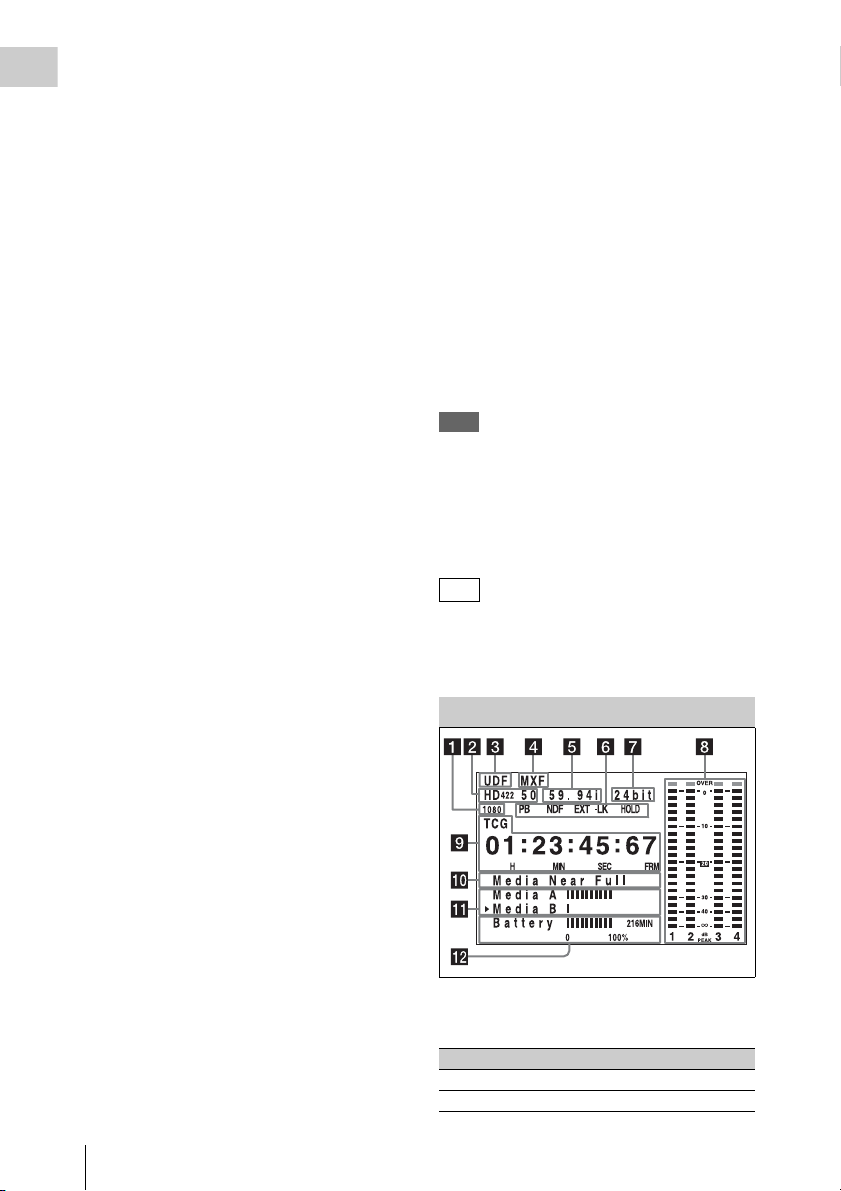
a Resolution
Indicates the resolution of HD output video.
Indication Resolution (horizontal × vertical)
1080 1080 lines (1920 × 1080)
720 720 lines (1280 × 720)
Page 27

b Recording format
Indicates the current recording format or the
recording format of clip being currently played.
•UDF mode
HD422 50
HD420 HQ
IMX50
DVCAM
• FAT mode
HQ1920
HQ1440
HQ1280
SP1440
DVCAM
c Recording mode
UDF: UDF mode
FAT: FAT mode
d File format
MXF: When the recording mode is UDF
MP4: When the recording mode is FAT-HD
mode
DV-AVI : When the recording mode is FAT-SD
mode
e System frequency
Indicates the system frequency of video being
currently played or recorded.
59.94i
29.97P
23.98P
50i
25P
59.94P
50P
Indication Status
Recording
mode
16bit FAT Any format
UDF • HD420 HQ
24bit UDF • HD422 50
Recording format
•DVCAM
• IMX (Audio Length is
set to16 bit)
• IMX (Audio Length is
set to24 bit)
h Audio level indicators
Indicate the audio recording or play levels of
channels 1 to 4.
i Time counter display
Switches displays of time counter values,
timecode, and user bits data, depending on the
position of the DISPLAY switch.
Displays the type of data currently shown in the
time counter, as follows.
TCG: Recorded timecode
TCR: Playback timecode
UBG: Recorded user bits
UBR: Playback user bits
CNT: Counter
CLK: Time display (when the PRESET/REGEN/
CLOCK switch is set to CLOCK)
When the HOLD button is pressed to hold the
timecode value, the timecode is displayed in the
format shown below. When the HOLD button is
pressed again to release the hold, the timecode is
displayed in the normal format.
Chapter 1 Overview
f Status display
PB: Appears during play.
NDF: Appears when non-drop-frame timecode is
selected.
EXT-LK: Appears when the internal timecode
generator is locked to an external signal input
to the TC IN (timecode input) connector.
HOLD: Appears when the operation mode of the
internal timecode generator is set to R-RUN
and stopped.
g Audio format
Indicates the audio recording format or the audio
format of clip being currently played.
The three dots indicates that timecode is
displayed in the hold mode.
j Warning indicator area
Displays warnings when trouble with recording
or moisture condensation occurs.
For details, see “Operation Warnings” on page 176.
You can also display the name of the next clip to
be recorded (see page 127).
k Remaining media capacity indicator
Shows bar segments indicating the remaining
capacity of recording media in the slots.
Locations and Functions of Parts and Controls
27
Page 28
l Remaining battery capacity indicator
Shows bar segments indicating the remaining
Chapter 1 Overview
battery capacity.
HDVF-20A Viewfinder (Optional)
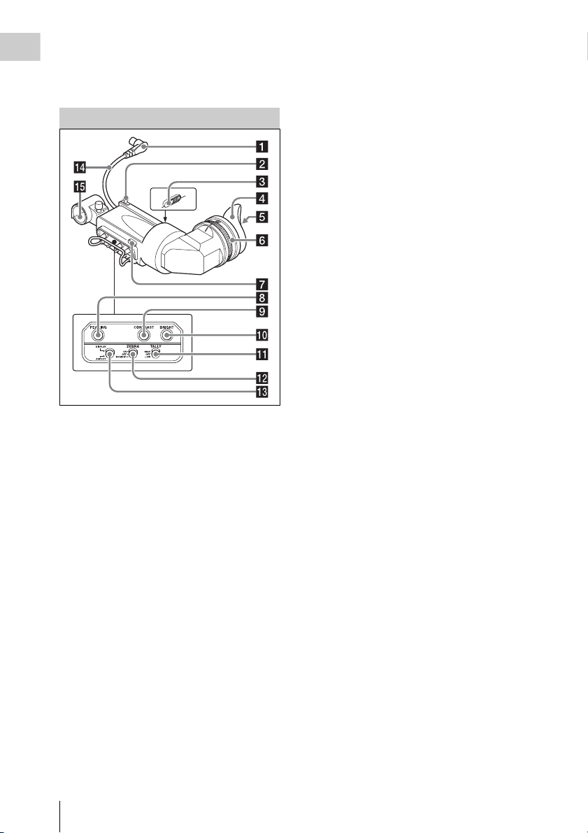
g Tally indicator
Lights up while camcorder is recording. Set the
TALLY switch to OFF when not in use. The
brightness can also be adjusted with the TALLY
switch.
This indica tor also flashes to indi cate warnings, in
the same manner as the camera operator tally
indicator and the recording/red tally indicators in
the viewfinder.
h PEAKING control
Turning this control clockwise adjusts the picture
sharpness, and makes focusing easier. This
control has no effect on the output signals of the
camcorder.
i CONTRAST control
Adjusts the contrast of the screen. This control
has no effect on the output signals of the
camcorder.
j BRIGHT control
Adjusts the brightness of the screen. This control
has no effect on the output signals of the
camcorder.
a Plug
Connect to the VF connector (20-pin) on the
camcorder.
b Stopper
Prevents the viewfinder from coming off the
camcorder when it is slid from side to side.
c Camera operator tally indicator
Lights up while camcorder is recording. This
indicator can be covered when not in use.
This indicator also flashes to indicate warnings, in
the same manner as the tally indicator and the
recording/red tally indicators in the viewfinder.
d Eyecup
e Indicators and status display
For details, see “Status Display on the Viewfinder
Screen” on page 30.
f Diopter adjustment ring
Allows for optimal focus adjustment.
Locations and Functions of Parts and Controls
28
k TALLY switch
Controls the tally indicator located on the front of
the viewfinder.
HIGH: The tally indicator brightness is set to
high.
OFF: The tally indicator is disabled.
LOW: The tally indicator brightness is set to low.
l ZEBRA (zebra pattern) switch
Controls the zebra pattern display on the
viewfinder screen as follows.
ON: A zebra pattern appears and stays.
OFF: The zebra pattern disappears.
MOMENT: A zebra pattern appears and stays for
about five seconds.
m DISPLAY/ASPECT switch
Turns the marker indication on and off, and
switches between 4:3 and 16:9 aspect ratios for
viewfinder screen display.
DISPLAY: When the marker indication is
enabled with the camcorder, the marker
indication on the viewfinder screen turns on
and off every time you push the switch up to
this position.
ASPECT: Each push of the switch down to this
position toggles the mask display on and off.
Page 29
(Make mask display settings using
OPERATION >Marker >Aspect Mask in the
setup menu (see page 119).)
n Viewfinder cable
o Microphone holder
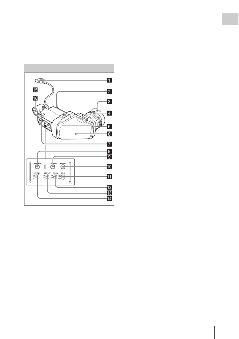
CBK-VF01 Viewfinder (Optional)
a Plug
Connect to the VF connector (26-pin) on the
camcorder.
b Stopper
Prevents the viewfinder from coming off the
camcorder when it is slid from side to side.
c Eyecup
d Diopter adjustment ring
Allows for optimal focus adjustment.
e Eyepiece
You can raise this up when required by the
situation.
f Viewfinder barrel
You can raise this up or rotate when required by
the situation.
g Tally indicator
Lights up when recording is started by a press of
the REC START button on this camcorder, the
VTR button on the lens, or the VTR button on the
remote control unit.
When an abnormality occurs, the tally indicator
flashes to indicate a warning.
h PEAKING control
Turning this control clockwise adjusts the picture
sharpness, and makes focusing easier. This
control has no effect on the output signals of the
camcorder.
i CONTRAST control
Adjusts the contrast of the screen. This control
has no effect on the output signals of the
camcorder.
j BRIGHT control
Adjusts the brightness of the screen. This control
has no effect on the output signals of the
camcorder.
k TALLY switch
Controls the tally indicator located on the front of
the viewfinder.
HIGH: The tally indicator brightness is set to
high.
OFF: The tally indicator is disabled.
LOW: The tally indicator brightness is set to low.
l ZEBRA (zebra pattern) switch
Controls the zebra pattern display on the
viewfinder screen as follows.
ON: Display a zebra pattern.
OFF: Do not display a zebra pattern.
m DISPLAY switch
Turns the display of text information on and off.
ON: Display text information.
OFF: Do not display text information.
n MIRROR switch
The image display on the monitor screen becomes
reversed horizontally or vertically when the
viewfinder barrel is raised up or rotated. Use this
switch to control the image display in such
situation.
Chapter 1 Overview
Locations and Functions of Parts and Controls
29
Page 30
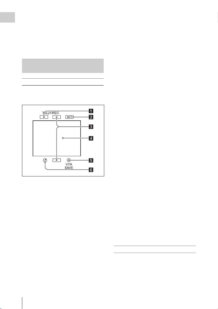
L/R: Reverse the image horizontally.
OFF: Do not reverse the image.
Chapter 1 Overview
B/T: Reverse the image vertically.
o Viewfinder cable
p Microphone holder
Status Display on the Viewfinder Screen
Indicators (HDVF-20A)
The following indicators are arranged above and
below the screen of the HDVF-20A to show the
current state and adjustments of the camcorder.
b BATT (battery) indicator
This indicator starts flashing when the battery
connected to the camcorder is nearly exhausted,
and stays lit when the battery is completely
exhausted.
To prevent interruption during operation, replace
the battery as soon as this indicator starts flashing.
The battery power level at which the indicator starts
flashing can be set by MAINTENANCE >Battery in
the setup menu. For details, see page 135.
c Recording/red tally indicators
Light when the camcorder is the following states.
• Recording with the MAINTENANCE >Camera
Config >HD/SDI Remote I/F menu item set to
[R-Tally]
• Green tally signal or call signal received (when
a camera adaptor is mounted on the camcorder
and a camera extension unit is connected)
These indicators also flash to indicate warnings,
in the same manner as the tally indicator and the
camera operator tally indicator.
d Viewfinder screen
See “Viewfinder screen display” (page 30).
e VTR SAVE indicator
Do not function on this camcorder.
a Green tally indicator
Lights when the camcorder is the following
states.
• Picture Cache mode enabled
• Green tally signal received (when a camera
adaptor is mounted on the camcorder and a
camera extension unit is connected)
• Recording with MAINTENANCE >Camera
Config >HD/SDI Remote I/F in the setup menu
set to [G-Tally]
Flashes when the camcorder is the following
states.
• Set to Interval Rec mode or the consecutive
mode of Frame Rec mode (1 flash per second)
• Recording in Interval Rec mode or recording in
the consecutive mode of Frame Rec mode (4
flashes per second)
• Set to the single-sho t mode of Frame Rec mode,
or recording in that mode (2 flashes per second)
Locations and Functions of Parts and Controls
30
f ! (warning) indicator
This indicator lights when any of the following
conditions occurs with the corresponding item set
to [On] by OPERATION >“!” LED in the setup
menu.
• The gain is set to other than 0 dB.
• The SHUTTER selector is set to ON.
• The WHITE BAL switch is set to PRST.
• ATW is enabled.
• The lens extender is used.
• The reference value of auto iris adjustment is
not the standard value.
• The FILTER selector is set to other than 1.
Viewfinder screen display
The viewfinder screen displays not only the video
picture but also characters and messages
indicating the camcorder settings and operating
status, a center marker, a safety zone marker, etc.
When the menu screen is not displayed and the
DISPLAY switch is set to ON, the items for
which an ON setting was made with
Page 31

OPERATION >Super Impose in the setup menu
or with related switches are displayed at the top
and bottom of the screen.
Caution messages are indicated for three seconds
when you carry out operations to change
camcorder settings. Adjustment execution
messages are indicated while adjustments
proceed. When adjustments are finished,
messages showing the results of adjustments
appear for three seconds.
Not only these indications are displayed on the
viewfinder screen, but a menu setting enables
them to be output as video signals.
All items that can be displayed on the viewfinder
screen are shown below.
Top of viewfinder screen
a Extender settings
Indicates the setting of the digital extender
function (when optional CBK-HD02 SDI/
COMPOSITE Input and 50 Pin Interface is
installed) of this camcorder and the setting of the
lens extender.
EX: The lens extender is on.
08: The lens shrinker is on.
x2D: The digital extender function of this
camcorder is on.
Ex2D: The lens extender and the digital extender
function of this camcorder are both on.
Digital extender function can be turned on or off
by an assignable sw itch to which Di gital Extender
is assigned.
Note
When slow & Quick motion is selected or the freeze mix
function is used, the digital extender cannot be turned on.
When the camcorder is in focus magnification (Focus
Mag) mode, turning on the digital extender cancels the
mode.
b Zoom position (when the lens is
mounted)
Indicates the zoom position of the zoom lens in
the range from 0 to 99.
c Focus position (when the serial lens is
mounted)
Indicates the focus position as distance to the
subject (in units of m).
d Green tally
Lights when the camcorder is the following
states.
• MAINTENANCE >Camera Config >HD-SDI
Remote I/F is set to [G-Tally] in the setup menu
and a recording control signal is output from the
HD/SD SDI OUT connector.
• When the Picture Cache mode is enabled
• Green tally signal received (when a camera
adaptor is mounted on the camcorder and a
camera extension unit is connected)
e Media status
Displays the name of the currently active media
slot (A or B).
f Special recording mode/operation
status
Indicates the current special recording mode/
operation status as follows.
Indication Meaning
zREC Recording in progress
STBY When recording is on a break in
CONT Standby for next recording in Clip
zCACHE Standby in Picture Cache mode
zINT REC Recording in progress in Interval
zINT STBY Standby for next recording in
INT STBY Standby in Interval Recording
zFRM REC Recording in progress in Frame
zFRM
STBY
FRM STBY Standby in Frame Recording mode
zS&Q REC Recording in progress in Slow &
Clip Continuous Rec mode or
standby in other modes
Continuous Rec mode
Recording mode
Interval Recording mode
mode
Recording mode
Standby for next recording in
Frame Recording mode
Quick Motion mode
Chapter 1 Overview
Locations and Functions of Parts and Controls
31
Page 32

Indication Meaning
Chapter 1 Overview
S&Q STBY Standby in Slow & Quick Motion
CALL
(displayed in
red)
BREVIEW During recording review
mode
Being called from a connected
device
g Wireless receiver reception level
When a wireless receiver is installed in the
camcorder, “W” appears together with four
segment reception level indicators for each of the
channels (1 to 4) that can be used by the receiver.
The indications are as follows.
In normal situation: The number of white
segments indicates the strength of the signal
level.
Muting (for an analog receiver) or error rate
aggravation (for a digital receiver): The
number of grey segments indicates the
strength of the signal level.
Reception level over peak: “P” is displayed
instead of the indicators.
1)
Tuner battery is low: The channel number and
indicator of the corresponding channel
1)
flash.
1) When an optional DWR-S01D is used
h Battery remaining/voltage capacity
The following is displayed depending on the type
of power source.
Type of pow er
source
InfoLithium
battery
Anton Bauer
battery
Other type than
above
What is displayed
Remaining battery capacity icon
and remaining recording time
Remaining battery capacity (%
indication)
Input voltage
i External power input
Appears when power is supplied from an external
power source connected to the DC IN connector.
j Color temperature
Displays a color temperature calculated from the
gain of R and B, in the range 1.5 K to 50.0 K (in
steps of 0.1 K). The +/– signs may be displayed
depending on the Offset White setting (see
page 124).
No display: Offset White is OFF
+: The value of Offset White is greater than
3200K.
–: The value of Offset White is less than 3200K.
k Number of system lines
Indicates the number of system lines (1080/720/
576/480/486
1)
) of video currently being recorded
or played back.
1) In SD mode, when OPERATION >Format >Country
is set to other than [PAL Area] in the setup menu.
In UDF mode: 486
In FAT mode: 480
In UDF mode, the system frequency is also
displayed here.
l Video format
Indicates the video format for recording (59.94i/
29.97P/23.98P/50i/25P/59.94P/50P) or the video
format of clip being currently played back (see
page 51).
The video aspect ratio (16:9 or 4:3) can also be
displayed when the recording format is set to
IMX50 or DVCAM.
m Depth of field indication (when the
serial lens is mounted and when the
CBK-VF01 is used)
Error/warning indication
A bar indicates the depth of field. The display unit
is meters or feet, as selected by OPERATION
>Display On/Off >Lens Info in the setup menu.
An error or warning message is displayed here
depending on the situation.
Under this area, you can also display the name of
the next clip to be recorded (see page 127).
n Special recording mode indication
The following is displayed when the camcorder is
in a special recording mode.
• Frame Rec (Frame Recording mode)
• Interval Rec (Interval Recording mode)
• S&Q Motion (Slow & Quick Motion mode)
o Special recording mode settings
indication
Appears when the camcorder is in a special
recording mode.
Locations and Functions of Parts and Controls
32
Page 33

Bottom of viewfinder screen
STD
a TLCS iris control mode
The following icons are displayed to indicate the
video level control modes based on the Total
Level Control System (TLCS).
Icon TLCS control mode
Backlight mode
S
Standard mode
Spotlight mode
Indication Meaning
zREC DV recording in progress
STBY Standby for DV recording
e Video level indication
An indication is displayed together with an
appropriate ND filter position number when the
light level of the subject is too high or too low.
f Timecode
Caution message
Indicates the elapsed recording/playback time,
timecode, user bits data or other information
selected by the DISPLAY switch (see page 22).
Also indicates a caution message when caution is
required such as when you try to change settings.
g Brightness level (when the CBK-VF01
is used)
Indicates the average brightness level (%) of the
detection area.
h External input source
Indicates the type of external input signal (HDV)
to be recorded.
Chapter 1 Overview
b Focus adjustment mode (when the auto
focus lens is mounted)
Indicates the current focus adjustment mode of
the camcorder.
• AF (Auto Focus mode)
• MF (Manual Focus mode)
• MF* (Manual Focus mode when the MF Assist
function is on)
• Full MF (Full Manual Focus mode)
c External device control
“REC2” is displayed when MAINTENANCE
>Camera Config >HD-SDI Remote I/F is set to
[Chara] in the setup menu and a recording control
signal is output from the HD/SD SDI OUT
connector.
d Operation status of connected i.LINK
device
The operating format (HDV or DV) and operation
status of that device are indicated as follows.
Indication Meaning
zREC HDV recording in progress
STBY Standby for HDV recording
i Recording of external input
Indicates “EXT” when an external input is
recorded.
j Electric color temperature filter
Appears when the CC 5600K function is set to on.
k Filter position
Indicates the currently selected ND filter position
number. (see page 17).
When ELECTRICAL CC is assigned to an
assignable switch, the electrical filter position (A/
B/C/D) appears to the right of the ND filter
position (1 to 4), as shown on the previous page.
l White balance memory
Indicates the currently selected white balance
automatic adjustment memory.
AT W: ATW (Auto Tracing White Balance) mode
W:A : Memory A mode
W:B : Memory B mode
W:P : Preset mode
3200: When the assignable switch to which Color
Temp SW 3200K has been assigned is on
4300: When the assignable switch to which Color
Temp SW 4300K has been assigned is on
Locations and Functions of Parts and Controls
33
Page 34

5600: When the assignable switch to which Color
Chapter 1 Overview
Temp SW 5600K has been assigned is on
6300: When the assignable switch to which Color
Temp SW 6300K has been assigned is on
m Gain value
Indicates the gain value (in dB) of the video
amplifier, as set by the GAIN selector.
n Shutter
Indicates the shutter speed or the shutter mode.
For details, see “Setting the Electronic Shutter”
(page 57).
o Audio level meters
Indicate the audio levels of channel 1 and
channel 2.
p Remaining media capacity
The available time for recording with the current
video format (recording bit rate) is calculated
according to the remaining space of each media
and indicated in time units of minutes. A lock
icon appears if the media is write-protected.
q Histogram (when the CBK-VF01 is
used)
Shows a pixel distribution of video luminance (in
HD mode only).
Reference
value
–1 ssssAll segments are lit in white.
Indicator
r Iris position (when the lens is mounted)
Indicates the iris position and the setting for iris
override (reference value for the lens iris) (see
page 59).
The iris override setting is indicated by four
segments indicator as follows.
Reference
value
+0.25
+0.5 xxLeft two segments are lit in grey.
+0.75 xxxLeft two segments and lower
+1 xxxxAll segments are lit in grey.
–0.25
–0.5 ssLeft two segments are lit in
–0.75 sssLeft two segments and lower
Locations and Functions of Parts and Controls
34
Indicator
Lower left segment is lit in grey.
x
right segment are lit in grey.
Lower left segment is lit in
s
white.
white.
right segment are lit in white.
Page 35

Chapter2 Preparations
Preparing a Power Supply
For safety, use only the Sony battery packs and
AC adaptors listed below.
• BP-GL95/GL65/L60S/L80S Lithium-ion
Battery Pack
• AC power using the AC-DN2B/DN10 AC
Adaptor
CAUTION
Danger of explosion if battery is incorrectly replaced.
Replace only with the same or equivalent type
recommended by the manufacturer.
When you dispose of the battery, you must obey the law
in the relative area or country.
ATTENTION
Il y a danger d’explosion s’il y a remplacement incorrect
de la batterie. Remplacer uniquement avec une batterie
du même type ou d’un type équivalent recommandé par
le constructeur.
Lorsque vous mettez la batterie au rebut, vous devez
respecter la législation en vigueur dans le pays ou la
région où vous vous trouvez.
VORSICHT
Explosionsgefahr bei Verwendung falscher Batterien.
Batterien nur durch den vom Hersteller empfohlenen
oder einen gleichwertigen Typ ersetzen.
Wenn Sie die Batterie entsorgen, müssen Sie die Gesetze
der jeweiligen Region und des jeweiligen Landes
befolgen.
Using a Battery Pack
When a BP-GL95/GL65/L60S/L80S Battery
Pack is used, the camcorder will operate
continuously for the time shown below.
Model name Operating time
BP-GL95 Approx. 180 minutes
BP-GL65 Approx. 120 minutes
BP-L60S Approx. 110 minutes
BP-L80S Approx. 145 minutes
WARNING
Batteries shall not be exposed to excessive heat such as
sunshine, fire or the like.
AVERTISSEMENT
N’exposez pas les batteries à une chaleur excessive, au
soleil ou près d’un feu par exemple.
WARNUNG
Akkus dürfen keinesfalls übermäßiger
Wärmeeinwirkung ausgesetzt werden, wie z.B.
Sonneneinstrahlung, Feuer o. ä.
Note
The battery pack operating time depends on the
frequency of use of the battery pack, and the ambient
temperature when used.
Before use, charge the battery pack with a charger
suitable for each battery.
For details on the battery charging procedure, refer
to the battery charger operation manual.
Note on using the battery pack
A warm battery pack may not be able to be fully
recharged.
To attach the battery pack
1 Press the battery pack against the back
of the camcorder, aligning the line on
the side of the battery pack with the
matching line on the camcorder.
Chapter 2 Preparations
Preparing a Power Supply
35
Page 36

Chapter 2 Preparations
1 BP-GL95/GL65/L60S/L80S
2 Align these lines.
2 Slide the battery pack down until its
“LOCK” arrow points at the matching
line on the camcorder.
1 “LOCK” arrow
2 Matching line on the camcorder
Note
If the battery pack is not attached correctly, the terminal
may be damaged.
To detach the battery pack
Holding the release button in, pull the battery
pack up.
Release button
Notes
• During recording and playback (while the ACCESS
lamp on the right-side panel is lit in blue and the
ACCESS lamp in the card slot section is lit in orange),
be careful never to remove the battery pack.
• Make sure to power the camcorder off before replacing
the battery pack.
Using AC Power
Mount an AC-DN2B/DN10 on the camcorder in
the same way as a battery pack, then connect to
the AC power supply.
The AC-DN2B/DN10 can supply up to 100 W of
power.
To an AC outlet
Preparing a Power Supply
36
Page 37

Attaching the Viewfinder
Viewfinder left-to-right positioning ring
Stopper
CAUTION
When the viewfinder is attached, do not leave the
camcorder with the eyepiece facing the sun. Direct
sunlight can enter through the eyepiece, be focused in the
viewfinder and cause fire.
Note
The viewfinder is supplied separately.
The following procedure is an example for attaching the
HDVF-20A.
For procedures for at taching other viewfinders, refer
to a manual supplied with each viewfinder.
Attaching the Viewfinder
Note
When attaching the viewfinder, make notes of the
following points.
• Be sure to the power off the camcorder before coupling
the viewfinder connector to the camcorder’s VF
connector (20-pin). If you make this connection when
the camcorder power is on, the viewfinder may not
function properly.
• Couple the viewfinder connector firmly to the
camcorder’s VF connector. If the coupling is loose,
noise may appear on the video or the tally light may not
operate properly.
For more information about the connection of the
viewfinder and camcorder, contact a Sony service
representative.
1 1 Loosen the viewfinder left-to-right
positioning ring, 2 attach the
viewfinder to the viewfinder fitting
shoe, and 3 tighten the viewfinder leftto-right positioning ring.
Chapter 2 Preparations
2 Couple the viewfinder connector to the
VF connector (20-pin).
VF connector (20-pin)
Detaching the viewfinder
You can carry out this by following the attaching
procedure in reverse order, but there is an
additional action to take: when detaching the
viewfinder from the fitting shoe, pull up the
stopper.
Adjusting the Viewfinder Position
To adjust the viewfinder left-right position,
loosen the left-right positioni ng ring, and to adjust
the front-back position, loosen the front-to-back
positioning knob.
Attaching the Viewfinder
37
Page 38

Viewfinder left-to-right positioning ring
Chapter 2 Preparations
Viewfinder front-to-back positioning knob
Using the BKW-401 Viewfinder Rotation Bracket
By fitting an optional BKW-401 Viewfinder
Rotation Bracket, you can rotate the viewfinder
out of the way so that your right leg does not hit
the viewfinder while you are carrying the
camcorder.
1 Loosen the front-to-back viewfinder
positioning levers and the front-to-back
viewfinder positioning knobs, and then
pull the viewfinder slide assembly
forward.
Bolts with
hexagonal
hole
Viewfinder slide assembly
3 Attach the BKW-401 with the supplied
bolts.
Bolts supplied with the BKW-401
2 Using a 2.5 mm diameter hexagonal
wrench, detach the viewfinder slide
assembly.
Attaching the Viewfinder
38
Page 39

4 Adjust the front-to-back position so
that the arm of the BKW-401 does not
touch the handle when it is raised.
Adjust position so that arm
does not touch handle
Detaching the Eyepiece
Removing the eyepiece gives a clearer view of the
screen from further away. It is also easy to
remove dust from the viewfinder screen and
mirror when the eyepiece is detached.
1 Turn the eyepiece locking ring fully
counterclockwise, to align the red
marks on the locking ring and the
viewfinder barrel.
To reattaching the eyepiece
1 Align the red marks on the eyepiece
locking ring and the viewfinder barrel.
2 Align the red mark on the end of the
eyepiece end with the red marks on the
eyepiece locking ring and the
viewfinder barrel. Then insert the
eyepiece into the viewfinder barrel.
3 Turn the eyepiece locking ring
clockwise until its “LOCK” arrow
points at the red mark on the viewfinder
barrel.
When the eyecup is worn out, replace it with a
new one.
For details of a replacement eyecup, contact a Sony
service representative.
Adjusting the Viewfinder Focus and Screen
To adjust the viewfinder focus
Turn the diopter adjustment ring until the
viewfinder image is sharpest.
Diopter adjustment ring
Chapter 2 Preparations
1 Locking ring
2 Locking ring match mark
3 Match mark on the viewfinder barrel
2 Detach the eyepiece.
Match mark on end of eyepiece
To adjust the viewfinder screen
Adjust the brightness, cont rast, and peaking of the
viewfinder screen with the controls shown below.
Attaching the Viewfinder
39
Page 40

Chapter 2 Preparations
1 PEAKING control
2 CONTRAST control
3 BRIGHT control
Setting the Area of Use
When using the camcorder for the first
time
The area of use is not factory preset. Before using
the camcorder, you need to set this item. (You
cannot use the camcorder without setting this
item.)
To set the area of use
POWER switch
MENU knob
1 Set the POWER switch to the ON
position.
The screen for setting the area of use appears
in the viewfinder.
Setting the Area of Use
40
Page 41

2 Press the MENU knob.
The settings for selectable areas of use are
displayed.
Setting the Date/Time of the Internal Clock
3 Turn the MENU knob to select the
desired area of use.
Setting Area of use
NTSC Area NTSC area (for areas other
than Japan)
NTSC(J) Area NTSC area (Japan)
PAL A rea PA L ar ea
a) The composite signal output from this camcorder
is an NTSC signal with a black setup (7.5 IRE).
The system frequency is 59.94i.
b) The composite signal output from this camcorder
is an NTSC signal with no black setup. The
system frequency is 59.94i.
c) The composite signal output from this camcorder
is a PAL signal. The system frequency is 50i.
a)
b)
c)
4 Set the following items.
• Time Zone
• Date/Time
See “Basic Setup Menu Operations”
(page 109).
5 Turn the MENU knob to select
“Finish”, then press the MENU knob.
The camcorder is now ready for use.
You can set or change the date and time of the
internal clock. The date and time set are reflected
in the timecode.
For menu operations, see “Basic Setup Menu
Operations” (page 109).
1 Select MAINTENANCE >Clock Set
>Date/Time in the setup menu.
2 Press the MENU knob.
The Date/Time setting window appears.
3 Turn the MENU knob to display the
desired value, and press the knob.
The selection shifts to the next item on the
right.
Chapter 2 Preparations
4 To continue the remaining settings,
repeat step 3.
5 Making sure that “SET” is selected,
press the MENU knob.
The internal clock is set with the date and
time set in steps 3 and 4.
To cancel the setting
Before executing step 5, push the MENU
CANCEL/PRST/ESCAPE switch up to the
CANCEL/PRST side.
Setting the Date/Time of the Internal Clock
41
Page 42

Mounting and Adjusting the Lens
Chapter 2 Preparations
Note
Always power the camcorder off before mounting or
removing a lens.
For information about using the lens, refer to the
operation manual for the lens.
Note
The lens is supplied separately.
Lens mount
securing rubber
Caution
If the lens is not firmly locked, it may come off
while the camcorder is being used. This could cause
a serious accident. Make sure the lens is firmly
locked. It is recommended that the lens mount
securing rubber be put on the lens locking lever as
illustrated above.
4 Connect the lens cable to the LENS
connector.
5 Secure the lens cable with the cable
clamps.
If you have attached an aberration correction
lens
The aberration correction function is activated
automatically. Starting the camcorder with an
aberration correction lens may require more time
than normally because of data loading at start-up.
Contact a Sony service representative for
information about aberration correction lenses.
Adjusting the Flange Focal Length
If the lens does not stay in focus properly as you
zoom from telephoto to wide angle, adjust the
flange focal length (the distance from the plane of
the lens mounting flange to the imaging plane).
Make this adjustment just one time after
mounting or changing the lens.
When carrying out the adjustment, use a flange
focal length adjustment chart as the subject.
1 Push the lens locking lever up and
remove the lens mount cap from the
lens mount.
2 Align the center pin on the lens with the
center slot in the lens mount, and insert
the lens into the mount.
3 Holding the lens in place, push the lens
locking lever down to lock the lens.
Mounting and Adjusting the Lens
42
About 3 m (10 ft)
Notes
• If you use a subject with insufficient contrast, or move
the camcorder or subject during adjustment, this will
cause an adjustment error.
• Place the subject (the flange focal length adjustment
chart) so that it appears at the center of the screen at the
telephoto end. Arrange so that no nearby object (no
object closer to the camera than the chart) enters the
screen at the wide-angle end.
Page 43

Carrying out the adjustment
1 Set the iris to manual.
2 Open the iris, position the supplied
flange focal length adjustment chart
approximately 3 meters (10 ft) away
from the camcorder, and arrange the
lighting to obtain a satisfactory video
output.
3 Loosen the fixing screws on the F.f or
F.B ring (flange focal length adjustment
ring).
4 Use manual or power zoom to set the
lens to telephoto.
5 Point the camcorder at the chart by
turning the focus ring and focus on it.
6 Set the zoom ring to wide angle.
7 Turn the F.f or F.B ring until the chart
is in focus, being careful not to disturb
the focus ring.
8 Repeat steps 4 to 7 until the chart stays
in focus all the way from wide angle to
telephoto.
Preparing the Audio Input System
Chapter 2 Preparations
Connecting a Microphone to the MIC IN Connector
You can attach the optional ECM-680S stereo
microphone to the microphone holder of the
viewfinder (optional).
The following procedure is an example for
attaching a microphone holder to the HDVF-20A.
For procedures for attaching a microphone holder
to other viewfinders, refer to a manual supplied with
each viewfinder.
1 Loosen the screw and open the
microphone holder clamp.
Microphone holder clamp
9 Tighten the F.f or F.B ring fixing
screws.
2 Place the microphone in the
microphone holder.
1 Wind the microphone spacer around
the microphone, while peeling off the
protective sheets on both sides of the
microphone spacer.
2 Place the microphone in the holder so
that “UP” is at the top.
3 Close the microphone holder.
4 Tighten the screw.
Preparing the Audio Input System
43
Page 44

Chapter 2 Preparations
On how to perform this operation, refer to the
operation manual for the microphone.
3 Plug the microphone cable into the MIC
IN connector, then set the AUDIO IN
switch for the channel on which you
want to record the audio from this
microphone to FRONT.
Connecting Microphones to the AUDIO IN Connectors
You can connect up to two monaural
microphones to the AUDIO IN CH-1/CH-2
connectors, using an optional CAC-12
Microphone Holder.
The following is the procedure for attaching an
electret condenser microphone such as the ECM674/678.
On how to attach the CAC-12, refer to the operation
manual for the CAC-12.
1 Attach the electret condenser
microphone.
1 Loosen the ball joint lock lever.
2 Wind the microphone spacer (sheet
type, supplied with the microphone)
around the microphone, while peeling
off the protective sheets on both sides
of the microphone spacer.
3 Place the microphone in the holder so
that “UP” is at the top.
4 Close the microphone holder.
5 Tighten the screw.
6 Position so that the microphone does
not interfere with the viewfinder and
tighten the ball joint lock lever.
4 Secure the microphone cable with the
cable clamp.
Preparing the Audio Input System
44
Microphone
Page 45

2 Connect the microphone cable to the
AUDIO IN CH-1 or CH-2 connector.
3 Set the switches as follows.
• Set the AUDIO IN selectors indicated
below, depending on the power supply type
of the microphone.
Internal power supply: MIC
External power supply: +48V
• Set the AUDIO IN CH1/CH2 switch for the
channel to which the microphone is
connected to REAR.
Notes
• If the input level on the camcorder is not at an
appropriate setting for the microphone sensitivi ty, loud
sounds may be distorted, and the signal-to-noise ratio
may be affected.
• In order for the AUDIO IN CH-1 and CH-2 connectors
on the camcorder to be able to provide a phantom 48 V
power supply, female XLR connectors (3-pin) are
fitted. If the microphone cable has a female connector,
use an adaptor.
• When you detach a CAC-12 Microphone Holder once
you have attached to the camcorder, be careful not to
lose the two screws fixing the CAC-12 (in step 1).
After detaching the CAC-12, be sure to put the two
screws back into their original places.
Attaching a UHF Portable Tuner (for a UHF Wireless Microphone System)
To use a Sony UHF wireless microphone system,
power the camcorder off and then fit one of the
following UHF portable tuners.
• DWR-S01D Digital Wireless Receiver
• WRR-855S UHF Synthesized Tuner Unit
• WRR-860A/861/862 UHF Synthesized
Diversity Tuner
For details of these units, refer to the operation
manuals for them.
Note
The optional WRR Mount Bracket (service part number:
A-8278-057-B) is required to fit the WRR-862.
For details, contact your vendor or a Sony service
representative
Chapter 2 Preparations
1 AUDIO IN selectors
2 Monaural microphone
3 AUDIO IN CH1/CH2 switches
4 To AUDIO IN CH-1 or CH-2 connector
4 Switch the input level to match the
sensitivity of the microphone used.
Switch the input level by changing the setting of
MAINTENANCE >Audio >Rear MIC CH1/
CH2 Ref in the setup menu (factory default
setting is –60 dB). For details, see page 137.
To fit the DWR-S01D or WRR-855S
1 Remove the four fixing screws holding
the cover of the portable tuner/receiver
housing slot located in the rear of the
camcorder, to remove the cover.
Preparing the Audio Input System
45
Page 46

2 Insert the DWR-S01D or WRR-855S
into the housing slot, and fasten the four
fixing screws.
DWR-S01D or WRR-855S
Chapter 2 Preparations
BP-GL65/GL95/L60S/L80S
Adjustment
screws
Mount plate
(supplied with
WRR-862)
Phillips type
screwdriver
3 Set the AUDIO IN selector for the
channel to which you want to input
audio signal to WIRELESS (see
page 23).
To fit the WRR-862 (when using a BPGL65/GL95/L60S/L80S Battery Pack)
1 Attach the WRR tuner fitting (not
supplied; service part number: A-8278057-B) to the back of the camcorder.
1 Use a Phillips type screwdriver to
tighten the four screws placed in the
tuner fitting. For three of these screws,
insert the screwdriver through the
corresponding hole and tighten the
screw.
Note
Make sure that all four screws are fully tightened.
2 Loosen the adjustment screws on the
tuner fitting.
3 Adjust the tuner fitting position for a
BP-GL65/GL95/L60S/L80S Battery
Pack to be attached, and tighten the
adjustment screws to fix its position.
4 Attach the mount plate supplied with
the WRR-862.
About the WRR tuner fitting (service part
number: A-8278-057-B), contact a Sony service
or sales representative.
2 Attach the battery pack.
On how to attach the battery pack, see “To
attach the battery pack” on page 35.
3 Mount the tuner on the WRR tuner
fitting.
WRR-862
4 Connect the tuner power cord to the DC
OUT connector of the camcorder, and
the audio output cable to the AUDIO IN
CH-1 or CH-2 connector.
5 Set the switches as follows.
• Set the AUDIO IN selector for the channel
to which the audio output cable is attached
to MIC.
• Set the AUDIO IN CH1/CH2/CH3/CH4
switch for the channel to which the audio
output cable is connected to REAR.
If the XLR connection automatic detection
function is on, the input signal for audio
recording is selected automatically, and
therefore this setting is not required.
Preparing the Audio Input System
46
Page 47

1 AUDIO IN CH1/CH2 switches
2 To DC OUT connector
3 To AUDIO IN CH-1 or CH-2 connector
4 AUDIO IN selectors
Connecting Line Input Audio Equipment
Connect the audio output connector of the audio
equipment that supplies the line input signal to the
AUDIO IN CH-1 or CH-2 connector.
Switch settings
Set the AUDIO IN selector for the channel to
which the audio signal source is connected to
LINE.
Selecting the audio inputs to be recorded
• With the XLR connection automatic detection
function being off (the factory default setting):
A signal must be selec ted for audio record ing by
setting the AUDIO IN CH1 or CH2 switch to
REAR depending on which of the AUDIO IN
CH-1 and CH-2 connectors is used for
connecting the external audio equipment.
• With the XLR connection automatic detection
function being on: When a cable is connected to
the AUDIO IN CH-1 or CH-2 connector, the
input from that connector is automatically
selected for audio recording, regardless of the
setting of the AUDIO IN CH1 or CH2 switch.
The XLR connection automatic detection
function can be switched on or off by
MAINTENANCE >Audio >Rear XLR Auto in
the setup menu.
1 AUDIO IN CH1/CH2 switches
2 To AUDIO IN CH-1 or CH-2 connector
3 Audio equipment
4 AUDIO IN selectors
Chapter 2 Preparations
Preparing the Audio Input System
47
Page 48

Tripod Mounting
Chapter 2 Preparations
1 Attach the optional VCT-14/U14
Tripod Adaptor to the tripod.
Tripod adaptor
2 Mount the camcorder on the tripod
adaptor.
Red button
Lever
Note
The tripod adaptor pin may remain in the engaged
position even after the camcorder is removed. If this
happens, press the red button and move the lever as
shown above until the pin returns to the stowed position.
If the pin remains in the engaged position, you will not
be able to mount the camcorder on the tripod adaptor.
Camera mount
Slide the camcorder forward along the
groove in the adaptor until it clicks.
To remove the camcorder from the tripod
adaptor
Hold down the red button and pull the lever in the
direction of the arrow.
Tripod Mounting
48
Page 49

Connecting a Video Light
Using the Shoulder Strap
With this camcorder, you can use the Anton
Bauer Ultralight 2 or equivalent video light
(powered by 12 V with maximum power
consumption of 50 W).
• If you connect the video light to the LIGHT
connector on the camcorder and set the LIGHT
switch to AUTO, you can turn the light on and
off automatically a s you start and stop recording
on this camcorder.
• The output of the LIGHT connector on the
camcorder is controlled to 12 V even when the
camcorder is supplied with over 12 V power
(through the DC IN connector or battery pack).
The brightness or color temperature of the light
will not change according to voltage increase.
Notes
• Do not use a video light with power consumption of
over 50 W.
• The brightness or color temperature of the light will
change when the voltage (supplied through the DC IN
connector or from the battery pack) is under 12 V.
To attach the video light
Fit the video light to the accessory fitting shoe on
the camcorder grip, and connect the video light
cable to the LIGHT connector.
Note
The accessory fitting shoe on the camcorder is of the
1
/4-inch tapped hole type. If you want to replace this with
a slide-type shoe, use the supplied cold shoe kit. On how
to fit the cold shoe kit, refer to “Using a External Hard
Disk” in the Supplement supplied in the CD-ROM
(labeled “Manuals for Solid-State Memory
Camcorder”).
Chapter 2 Preparations
To attach the shoulder strap
1 Fit one of the clips to a shoulder strap
fitting.
Pull up the strap to lock the fitting.
Clip
2 Fit the other clip to the shoulder strap
fitting on the other side of the grip in the
same way as in step 1.
Connecting a Video Light / Using the Shoulder Strap
49
Page 50

To remove the shoulder strap
Press here and pull in the direction
shown by the arrow to release.
Adjusting the Shoulder Pad Position
Chapter 2 Preparations
You can slide the shoulder pad back and forth
within a 40 mm range. This adjustment helps you
get the best balance for shooting with the
camcorder on your shoulder.
Shoulder pad
1 Raise the lever in the center of the
shoulder pad to unlock the shoulder
pad.
2 Slide the shoulder pad backward or
forward until it is in the most
convenient position.
Adjusting the Shoulder Pad Position
50
3 Bring down the lever to lock the
shoulder pad in the selected position.
Page 51

Chapter3 Adjustments and Settings
For menu operations, see “Basic Setup Menu Operations” (page 109).
Setting the Video Format
The following recording formats can be selected for different combinations of video resolution and system
frequency.
In UDF mode
UDF
OPERATION >Format menu settings Video format (recording
HD/SD HD System
Line
HD 1080 HD422
720 HD422
SD — IMX50
Rec Format
50
HD420
HQ
50
HD420
HQ
c)
c)
DVCAM
System Frequency
59.94i HD422 1920/59.94i 1920×1080
50i HD422 1920/50i
29.97P HD422 1920/29.97P
25P HD422 1920/25P
23.98P HD422 1920/23.98P
59.94i HQ 1440/59.94i 1440×1080
50i HQ 1440/50i
29.97P HQ 1440/29.97P
25P HQ 1440/25P
23.98P HQ 1440/23.98P
59.94P HD422 1280/59.94P 1280×720
50P HD422 1280/50P
29.97P HD422 1280/29.97P
25P HD422 1280/25P
23.98P HD422 1280/23.98P
59.94P HQ 1280/59.94P
50P HQ 1280/50P
b)
23.98P
59.94i IMX50/59.94i 720×486
50i IMX50/50i 720×576
d)
29.97P
d)
25P
IMX50/25P 720×576
59.94i DVCAM/59.94i 720×480
50i DVCAM/50i 720×576
d)
29.97P
d)
25P
format/system frequency)
a)
HQ 1280/23.98P
IMX50/29.97P 720×486
DVCAM/29.97P 720×480
DVCAM/25P 720×576
Frame size
Chapter 3 Adjustments and Settings
Setting the Video Format
51
Page 52

a) 59.94i/29.97P/59.94P/23.98P: When OPERATION >Format >Country in the setup menu is set to [NTSC Area] or
[NTSC(J) Area]
50i/25P/50P: When OPERATION >Format >Country in the setup menu is set to [PAL Area]
b) 59.94i after 2-3 pulldown is recorded
c) When the optional CBK-MD01 is installed
d) Converted to PsF and recorded
In FAT mode
FAT
OPERATION >Format menu settings Video format (recording
format/system frequency)
HD/SD HD System
Chapter 3 Adjustments and Settings
Line
Rec Format
System Frequency
a)
HD 1080 HQ 1920 59.94i HQ 1920/59.94i 1920×1080
50i HQ 1920/50i
29.97P HQ 1920/29.97P
25P HQ 1920/25P
23.98P HQ 1920/23.98P
HQ 1440 59.94i HQ 1440/59.94i 1440×1080
50i HQ 1440/50i
29.97P HQ 1440/29.97P
25P HQ 1440/25P
23.98P HQ 1440/23.98P
SP 1440 59.94i SP 1440/59.94i
50i SP 1440/50i
b)
23.98P
SP 1440/23.98P
720 HQ 1280 59.94P HQ 1280/59.94P 1280×720
50P HQ 1280/50P
29.97P HQ 1280/29.97P
25P HQ 1280/25P
23.98P HQ 1280/23.98P
SD — DVCAM
c)
59.94i DVCAM/59.94i 720×480
50i DVCAM/50i 720×576
d)
29.97P
d)
25P
a) 59.94i/29.97P/59.94P/23.98P: When OPERATION >Format >Country in the setup menu is set to [NTSC Area] or
[NTSC(J) Area]
50i/25P/50P: When OPERATION >Format >Country in the setup menu is set to [PAL Area]
b) 59.94i after 2-3 pulldown is recorded
c) When the optional CBK-MD01 is installed
d) Converted to PsF and recorded
DVCAM/29.97P 720×480
DVCAM/25P 720×576
Frame size
Setting the Video Format
52
Page 53

Selecting the Recording Mode
Select the recording mode between UDF and
FAT.
1 Select OPERATION >Format >File
System in the setup menu (see
page 112).
2 Turn the MENU knob to select [UDF]
or [FAT], and press the knob.
A confirmation message appears.
3 Select [Execute] to execute, or select
[Cancel] to cancel, and then press the
MENU knob.
4 Power the camcorder off and on again.
Changing the Video Format
4 Select [Execute] to execute, or select
[Cancel] to cancel, and then press the
MENU knob.
5 When the setting of HD/SD or Country
was changed, power the camcorder off
and on again.
Chapter 3 Adjustments and Settings
Refer to the above table and change the settings of
the relevant items.
1 Select OPERATION >Format in the
setup menu (see page 112).
2 Turn the MENU knob to select the item
to change, and press the knob.
3 Turn the MENU knob to change the
setting, and press the knob.
A confirmation message appears.
Setting the Video Format
53
Page 54

Adjusting the Black Balance and the White Balance
To ensure excellent im age quality when using this
camcorder, conditions may require that both the
black balance and the white balance be adjusted.
Black balance and white balance adjustment
values that are automatically set by the camcorder
and the various settings are stored in the
Chapter 3 Adjustments and Settings
camcorder memory and retained even when the
power is turned off.
Black balance adjustment
The black balance will require adjustment in the
following cases.
• When the camcorder is used for the first time
• When the camcorder has not been used for a
long time
• When the camcorder is used under conditions in
which the surrounding temperature has changed
greatly
• When the GAIN selector (L/M/H/Turbo) values
have been changed by using OPERATION
>Gain Switch in the setup menu.
It is not usually necessary to adjust the black
balance when using the camcorder after it has
been off.
White balance adjustment
Always readjust the white balance when the
lighting conditions change.
Adjusting the Black Balance
In automatic black balance mode, adjustments are
performed in the following order: black set and
black balance. Manual black balance adjustment
can be selected from the setup menu.
Automatic black balance adjustment is disabled
in the following case.
• During recording
• In a special recording modes (Picture Cache
Rec, Interval Rec, Frame Rec, Slow & Quick)
• When the shutter mode is SLS
2 Push the AUTO W/B BAL switch to
BLACK and release the switch.
The message “Executing...” appears during
execution, and changes to “Done” when the
adjustment finishes. Adjustment values are
saved to memory automatically.
Notes
• During the black balance adjustment, the iris is
automatically closed.
• During the black balance adjustment, the gain
selection circuit is automatically activated so you may
see flickering on the viewfinder screen, but this is not
a fault.
• Output from the i. LINK connector stops temporarily if
you execute black balance adjustment during i.LINK
output. Output from the connector resumes when black
balance adjustment finishes.
If automatic black balance adjustment
cannot be made
If the black balance adjustment cannot be
completed normally , an error message will a ppear
for about three seconds on the viewfinder screen.
Possible messages are listed below.
Error message Meaning
NG: Iris Not
Closed
NG: Timeout Adjustment could not be
NG: Out of
Range
If any of the above error messages is displayed,
retry the black balance adjustment.
If the error message occurs again, an internal
check is necessary.
For information about this internal check, refer to
the Maintenance Manual.
Note
If the lens cable is not firmly connected to the LENS
connector, it may not be possib le to adjust the lens iris. If
this happens, the black balance will be incorrect.
The lens iris did not close;
adjustment was impossible.
completed within the standard
number of attempts.
The difference between the
reference value and the current
value is so great that it exceeds
the range. Adjustment was
impossible.
1 Set the OUTPUT/DCC switch to CAM.
Adjusting the Black Balance and the White Balance
54
Page 55

Adjusting the White Balance
1 Set the switches and selectors as shown
below.
• GAIN switch: L (set to a gain value that is
as small as possible)
• OUTPUT/DCC switch: CAM
• WHITE BAL switch: A or B
1) Adjustment values are saved to memory B only
when OPERATION >White Setting >White
Switch<B> in the setup menu, is set to
[Memory].
1)
2 Set the FILTER selector to suit the
lighting conditions as follows.
3 Place a white test card under the same
lighting conditions as for the subject to
be shot and zoom up to it.
Alternatively, any white object such as a
cloth or a wall can be used.
The absolute minimum white area is as
follows.
Rectangle centered on the screen. The
lengths of the sides are 70% of the length
and width of the screen.
Note
Make sure there are not bright spots in the
rectangle.
4 Adjust the lens iris.
Manually adjusted lens: set the iris to an
appropriate setting.
Lens with automatic iris: set the automatic/
manual switch on the lens to automatic.
5 Push the AUTO W/B BAL switch to
WHITE and then release the switch.
The message “Executing...” appears during
execution, and changes to “OK: (color
temperature of subject)” when the
adjustment finishes.
The adjustment values are saved
automatically in the memory selected in
step 1 (A or B).
Note
If the camcorder has a zoom lens with an automatic
iris, the iris may hunt
prevent this, adjust the iris gain knob (indicated as
IG, IS, or S) on the lens.
For details, refer to the lens operation manual.
1) Hunting: Repeated brightening and darkening of
the image, resulting from repeated response to
automatic iris control.
If the automatic white balance adjustment
cannot be made
If the white balance adjustment cannot be
completed normally , an error message will a ppear
for about three seconds on the viewfinder screen.
Possible messages are listed below.
Error message Meaning
NG: Low Light The white video level is too low.
NG: Timeout Adjustment could not be
NG: High Light The white video level is too
If any of the above error messages is displayed,
retry the white balance adjustment. If the error
message occurs again, an internal check is
necessary.
For information about this internal check, refer to
the Maintenance Manual.
1)
during the adjustment. To
Either open the lens iris or
increase the gain.
completed within the standard
number of attempts.
high. Either stop down the lens
iris or change the ND filter.
If you have no time to adjust the white
balance
Set the WHITE BAL switch to PRST.
This makes it possible to automatically set the
white balance to 5600 K (factory default value) by
pressing the COLOR TEMP. button.
The color temperature to which the white balance
is set when the COLOR TEMP. button is pressed
can be selected from among 3200K, 4300K,
5600K, and 6300K on OPERATION
>Assignable SW in the setup menu. You can also
assign color temperatures to the ASSIGN. 1/3
switches or ASSIGNABLE 4/5 switches.
Chapter 3 Adjustments and Settings
Adjusting the Black Balance and the White Balance
55
Page 56

To change the color temperature when
the ND filter is switched
You can assign electrical CC (color correction)
filters to ND filters (see page 17). This allows you
to change the color temperature automatically
when the ND filter is switched.
1 Set MAINTENANCE >White Filter
>ND Filter C.Temp in the setup menu
(see page 143) to On.
2 To assign an electrical CC filter to
Chapter 3 Adjustments and Settings
FILTER selector position number 1,
select [ND FLT C.Temp<1>]. To assign
it to positions 2 to 4, select [ND FLT
C.Temp<2-4>].
3 Turn the MENU knob to select the
desired color temperature.
As you turn the MENU knob, the color
temperature changes as follows: 3200K y
4300K y 5600K y 6300K.
4 Repeat steps 2 and 3 as required.
To switch between electrical CC filters
with an assignable switch
You can assign the function that switches
between electrical CC filters to an assignable
switch. This allows you to switch between color
temperatures (3200K/4300K/5600K/6300K) that
have been assigned to up to four positions (A to
D) with each press of the assignable switch.
Regardless of assignments to assignable
switches, you can also switch between the color
temperatures assigned to each position from a
RM-B150/B750 Remote Control Unit.
To set no color temperature
Select “-----” with
selected.
When the assignable switch is pressed, the
setting for that position is not displayed. For
example, if “-----” is set for one position, then
switching between the remaining three
positions is carried out.
Electrical CC<C> or <D>
3 Repeat step 2 as required.
4 Assign the electrical CC filter switching
function (ELECTRICAL CC) to an
assignable switch (see page 158).
White balance memory
Values stored in memory are held until the white
balance is next adjusted even when the camcorder
power is turned off.
The camcorder has two white balance memories,
A and B. You can automatically save adjustment
values for each ND filter in the memory that
corresponds to the WHITE BAL switch setting
(A or B). The camcorder has four built-in ND
filters, allowing you to save a total of eight
adjustment values (4 × 2). However, the contents
of the memories are not linked to ND filter
settings in the following cases.
• When the number of memories allocated to
each of A and B is limited to one by setting
OPERATION >White Setting >Filter White
Memory in the setup menu to Off.
• When the electrical CC filter switching function
has been assigned to an assignable switch, or
when a remote control unit has been connected.
(In these cases, the contents of white balance
memory are linked to electrical CC filter
positions (A to D).)
1 Select MAINTENANCE >White Filter
in the setup menu (see page 143).
2 Select the position to which to assign a
CC filter by selecting one of [Electrical
CC<A>] to [Electrical CC <D>], and
then turn the MENU knob to select the
desired color temperature.
As you turn the MENU knob, the color
temperature changes as follows: 3200K y
4300K y 5600K y 6300K.
Adjusting the Black Balance and the White Balance
56
Also, when OPERATION >White Setting
>White Switch<B> in the setup menu is set to
[ATW (Auto Tracing White Balance)], and the
WHITE BAL switch is set to B, the ATW
function is activated to automatically adjust the
white balance of the picture being shot for
varying lighting conditions.
Page 57

Setting the Electronic Shutter
Shutter Modes
The shutter modes that can be used with the
electronic shutter and the shutter speeds that can
be selected are listed below.
Standard mode
Select this mode for shooting fast-moving
subjects with little blurring.
You can set the shutter speed in one of two shutter
modes: Speed mode, in which the speed is set in
seconds, and Angle mode, in which the speed is
set in degrees.
Speed mode
System
frequency
59.94i
59.94P
50i
50P
29.97P
25P
23.98P
a) This speed cannot be selected when the camcorder is
in Slow & Quick Motion mode and OPERATION
>Rec Function >Frame Rate in the setup menu is set
to a value that is greater than the system frequency.
Angle mode
180°, 90°, 45°, 22.5°, and 11.25°
ECS (Extended Clear Scan) mode
Select this mode for obtaining images with no
horizontal bands of noise when shooting subjects
such as monitor screens.
As shown in the following tables, the range of
shutter speeds that can be set varies depending on
whether the Slow & Quick Motion (S&Q)
function is on or off.
Shutter speed (unit: seconds)
1
1
1
/
/
/
, 1/
, 1/
60,
100,
a), 1
, 1/
a), 1
, 1/
a), 1
, 1/
1
/
/
500
/
500
/
125
2000
50a),
, 1/
50
, 1/
a), 1
48
, 1/
a), 1
120
1
/60, 1/
1000
/
1000
/
250
60,
50
, 1/
1
/
1000
1
/
40
1
/
250
1
/
33
1
/
250
1
/
32
1
/
120,
125
100,
, 1/
2000
1
/
100
, 1/
2000
a), 1
/60, 1/96, 1/
500
, 1/
, 1/
250
1
/
120
, 1/
120,
1000
, 1/
, 1/
500
1
125
/
125
100
2000
,
System lines: 1080
System
frequency
Shutter speed (unit: Hz)
S&Q: Off S&Q: On
59.94i 60.00 to 3800 —
50i 50.00 to 3500 —
29.97P 29.99 to 4100 32.01 to 4100
23.98P 23.99 to 3700 32.02 to 3700
25P 25.00 to 3900 32.03 to 3900
System lines: 720
System
frequency
Shutter speed (unit: Hz)
S&Q: Off S&Q: On
59.94P 60.07 to 4100 32.01 to 4100
50P 50.03 to 3900 32.03 to 3900
29.97P 29.99 to 4100 32.01 to 4100
23.98P 23.99 to 3700 32.02 to 3700
25P 25.00 to 3900 32.03 to 3900
SLS (slow speed shutter) mode
Select this mode for shoot ing subjects in low level
lighting conditions.
OPERATION >Format
>HD System Line setting
Number of
accumulated frames
in the setup menu
1080 2, 3, 4, 5, 6, 7, 8, 16
720 2, 4, 6, 8, 16
Notes
,
• SLS mode cannot be used when the video format is SP
,
,
1440/23.98P or when the camcorder is in Slow &
Quick Motion mode.
• It is not poss ible to use SLS mode when OPERATION
>Input/Output >i.Link I/O is set to [Enable] in the
setup menu.
• It is not possible to output the color bar signal, turn the
SLS mode on or off, or change the number of
accumulated frames when the number of accumulated
frames is set to 16.
Selecting the Shutter Mode and Shutter Speed
Notes
• When the autom atic iris is used, the iris opens wider as
the shutter speed increases, thus reducing the depth of
field.
• The selectable shutter speeds vary depending on the
current system frequency.
Chapter 3 Adjustments and Settings
Setting the Electronic Shutter
57
Page 58

To switch between Speed mode and
Angle mode
1 Select OPEARTION >Shutter Select
>Shutter Select in the setup menu (see
page 124).
2 Turn the MENU knob to select Second
or Degree, and then press the knob.
To set the shutter speed in ECS mode
1 Set the shutter mode to ECS (see the
previous item).
2 Turn the MENU knob to select the
desired frequency or number of frames.
To set the shutter speed in SLS mode
To set the shutter mode and standardmode shutter speed
Chapter 3 Adjustments and Settings
Once the shutter speed is selected, it is retained
even when the camcorder power is turned off.
1 Push the SHUTTER selector from ON
to SELECT.
The current shutter setting indication appears
for about three seconds.
2 Before the shutter setting indication
disappears, push the SHUTTER
selector down to SELECT again and
repeat this until the desired mode or
speed appears.
When all modes and speeds are displayed,
the display changes in the following order.
Speed Mode (with system frequency 59.94i)
ECS Mode
Note
Depending on the frame rate setting (see page 83), some
shutter speeds cannot be selected in Slow & Quick
Motion mode. These speeds are replaced by the slowest
selectable shutter speed.
Example: If you perform Slow & Quick Motion
shooting when setting the frame rate to 60 and the video
format to HQ1280/29.97P
The shutter speed is indicated as follows.
1 Set OPERATION >Shutter >Slow
Shutter in the setup menu to [On] (see
page 124).
2 Select the desired number of
accumulated frames with
OPERATION >Shutter >SLS Frames
in the setup menu.
When Slow & Quick Motion mode is off
1/40t1/50t1/60t1/100t...
When Slow & Quick Motion mode is on
1/60t1/60t1/60t1/100t...
Setting the Electronic Shutter
58
Page 59

Changing the Reference Value for Automatic Iris Adjustment
The reference value for automatic iris adjustment
can be changed to aid the shooting of clear
pictures of back-lit subjects, or to prevent blownout highlights. The reference value for the lens
iris can be set within the following range with
respect to the standard value.
• 0.25 to 1 (increasing by increments of 0.25):
About 0.25 to 1 stop further open
• –0.25 to –1 (decreasing by increments of 0.25):
About 0.25 to 1 stop further close
Also you can set the area where light detection
occurs.
To change the reference value
1 Set OPERATION >Auto Iris >Iris
Override in the setup menu to On (see
page 122).
2 Set the MENU ON/OFF switch to OFF.
3 Turn the MENU knob to change the
reference value.
Note
Be sure to confirm that the current shutter mode is
not ECS.
An indicator of the current reference value is
shown at the iris position indication (see
page 34) on the viewfinder screen.
To make the iris more open
Turn the MENU knob counterclockwise as
seen from the front of the camcorder.
Select one of 0.25, 0.5, 0.75, or 1.
To stop down the iris
Turn the MENU knob clockwise as seen
from the front of the camcorder.
Select one of –0.25, –0.5, –0.75, or –1.
The changed reference value is retained until
the power of the camcorder is turned off.
Even if the reference value is changed, it
reverts to the standard value every time the
power is turned on.
To set the automatic iris window
1 Set OPERATION >Auto Iris >Iris
Window Indication in the setup menu to
On.
The current automatic iris window appears
on the viewfinder screen.
If it is not necessary to display the auto iris
window on the screen, set to Off.
2 Turn the MENU knob to select Iris
Window, and then press the knob.
3 Turn the MENU knob until the desired
auto iris window appears, and then
press the knob.
The shaded parts indicate the
area where light detection
If you select “Var”, the following items
become effective and you can set the window
of the desired size. Set the following items
with MAINTENANCE >Auto Iris2.
Item Setting
Iris Var Width The width of the window
Iris Var Height The height of the window
Iris Var H Pos The position of the window
in the horizontal direction
Iris Var V Pos. The position of the window
in the vertical direction.
When you exit the menu, the auto iris window
selected in step 3 appears.
Unless you need to keep this window displayed,
set OPERATION >Auto Iris >Iris Window
Indication in the setup menu to Off.
To counter problems with very bright
highlights
If the subject is too bright, the iris may close too
much, leaving the overall image dark, or the
highlights may be blown out. In such cases,
setting the highlight clip function on reduces the
luminance range, avoiding problems from the
automatic iris correction.
Set OPERATION >Auto Iris >Clip High Light in
the setup menu to On.
Chapter 3 Adjustments and Settings
Changing the Reference Value for Automatic Iris Adjustment
59
Page 60

Adjusting the Audio Level
When you set the AUDIO SELECT switch to
AUTO, the input levels of analog audio signals
recorded on each channel are adjusted
automatically. You can also make manual
adjustments.
Chapter 3 Adjustments and Settings
Note
Even if you set the AUDIO SELECT switch to AUTO,
the input levels of digital audio signals are not adjusted
automatically.
Target audio level for manual audio level
adjustment
Make adjustment using –20 dB as the target level.
If the audio level meter shows a maximum level
of 0 dB, then it indicates that the input audio level
is excessive.
Excessive input level
Target input level
Manually Adjusting the Audio Levels of the Audio Inputs from the AUDIO IN CH-1/CH-2 Connectors
1 To adjust the signal input to the AUDIO
IN CH-1 or CH-2 connector, set the
AUDIO IN CH1 or CH2 switch to
REAR.
To adjust both input signals, set both
switches to REAR.
2 Set the AUDIO SELECT switch(es)
corresponding to the channel(s) selected
in step 1 to MANUAL.
3 With the LEVEL knob(s) for the
channel(s) selected in step 1, adjust so
that the audio level meter shows up to
–20 dB for a normal input volume.
Correspondence between recording level
adjustments and audio level controls
On MAINTENANCE >Audio in the setup menu,
you can select which audio level control controls
the audio recording level of the input to each of
the AUDIO IN CH-1/CH-2 connectors. The
correspondence s between the settings of the m enu
items and the controls are as follows.
Rear1/WRR Level: Channel 1 recording level
Setting Knob
Side1 LEVEL (CH1) knob
Front MIC LEVEL control
Front+Side1 LEVEL (CH1) knob and MIC
LEVEL control (linked
operation)
Rear2/WRR Level: Channel 2 recording level
Setting Knob
Side2 LEVEL (CH2) knob
Front MIC LEVEL control
Front+Side2 LEVEL (CH2) knob and MIC
LEVEL control (linked
operation)
Note
When you have operation of the LEVEL (CH1/CH2)
knobs and MIC LEVEL control linked together, if the
MIC LEVEL control is set to 0, the audio signals on
channels 1 and 2 cannot be recorded. Check the position
of the MIC LEVEL control before adjusting the LEVEL
(CH1/CH2) knobs.
Manually Adjusting the Audio Level of the MIC IN Connector
1 Set either or both of the AUDIO IN
switch(es) to FRONT.
Adjusting the Audio Level
60
Page 61

2 Set the AUDIO SELECT switch(es) for
the desired channel(s) selected in step 1
to MANUAL.
3 Turn the MIC LEVEL control, and
adjust so that the audio level meter
shows up to –20 dB for a normal input
volume.
Correspondence between r ecording level
adjustments and audio level controls
On MAINTENANCE >Audio in the setup menu,
you can select which audio level control controls
the audio recording level of the front microphone
input. The correspondences between the settings
of the menu items and the controls are as follows.
MIC CH1 Level: Channel 1 recording level
Setting Knob
Side1 LEVEL (CH1) knob
Front MIC LEVEL control
Front+Side1 LEVEL (CH1) knob and MIC
LEVEL control (linked
operation)
MIC CH2 Level: Channel 2 recording level
Setting Knob
Side2 LEVEL (CH2) knob
Front MIC LEVEL control
Front+Side2 LEVEL (CH2) knob and MIC
LEVEL control (linked
operation)
Note
When you have operation of the MIC LEVEL control
and LEVEL (CH1/CH2) knobs linked together, if the
LEVEL (CH1/CH2) knobs are set to 0, the audio signals
on channels 1 and 2 cannot be recorded. Check the
position of the LEVEL (CH1/CH2) knobs before
adjusting the MIC LEVEL control.
Recording Audio on Channels 3 and 4
CH3 switch Channel 3 recording target
FRONT Front microphone audio
REAR Audio signal input to AUDIO IN
CH1 connector
WIRELESS Wireless microphone audio
CH4 switch Channel 4 recording target
FRONT Front microphone audio
REAR Audio signal input to AUDIO IN
CH2 connector
WIRELESS Wireless microphone audio
You can have the selection made automatically,
as follows.
To automatically select the same audio as on
channels 1 and 2
Set MAINTENANCE >Audio >Audio CH3/4
Mode of the setup menu to [Ch1/2].
Adjusting the audio recording levels
To adjust automatically
Set the AUDIO SELECT CH 3-4 switch to
AUTO.
To adjust manually
1 Set the AUDIO SELECT CH 3-4 switch
to MANUAL.
2 Select the knobs that adjust the audio
levels with the Audio CH3 Level and
Audio CH4 Level items under
MAINTENANCE >Audio in the setup
menu.
Audio CH3 Level: Channel 3 recording
level
Setting Knob
Side3 LEVEL (CH3) knob
Front MIC LEVEL control
Front+Side3 LEVEL (CH3) knob and
MIC LEVEL control (linked
operation)
Chapter 3 Adjustments and Settings
Selecting the recorded audio
You can select the audio recorded on audio
channels 3 and 4 with the AUDIO IN CH3/CH4
switches.
Audio CH4 Level: Channel 4 recording
level
Setting Knob
Side4 LEVEL (CH4) knob
Front MIC LEVEL control
Adjusting the Audio Level
61
Page 62

Chapter 3 Adjustments and Settings
Setting Knob
Front+Side4 LEVEL (CH4) knob and
MIC LEVEL control (linked
operation)
You can now adjust the levels of audio
channels 3 and 4 with the knobs selected
here.
Setting the Time Data
Note
When picture cache mode is enabled, it is not possible to
set time data, even if you set the F-RUN/SET/R-RUN
switch to SET. If you want to set time data, first exit
picture cache mode.
Setting the Timecode
The timecode setting range is from 00 : 00 : 00 :
00 to 23 : 59 : 59 : 29 (hours : minutes : seconds :
frames).
1 Press the DISP SEL/EXPAND button to
switch the display in the LCD monitor
to status display.
2 Set the DISPLAY switch to TC.
3 Set the PRESET/REGEN/CLOCK
switch to PRESET.
4 Set the F-RUN/SET/R-RUN switch to
SET.
The first (leftmost) digit of timecode flashes.
Setting the Time Data
62
5 Use the up and down arrow buttons to
change values, and use the left and right
arrow buttons to move the flashing
digit. Repeat until all digits are set.
To reset the timecode value to 00:00:00:00
Press the RESET/RETURN button.
6 Set the F-RUN/SET/R-RUN switch to
F-RUN or R-RUN.
F-RUN: Free run. The timecode generator
keeps running.
R-RUN: Recording run. The timecode
generator runs only while recording.
To set the drop frame mode/non-drop frame
mode
You can select the drop frame (DF) mode or nondrop frame (NDF) mode on MAINTENANCE
>Timecode in the setup menu.
Page 63

To make the timecode consecutive
When the F-RUN/SET/R-RUN switch is set to
R-RUN, recording a number of scenes on the
media normally produces consecutive timecode.
However, once you remove the media and record
on another media, the timecode will no longer be
consecutive when you use the original media
again for recording. In this case, to make the
timecode consecutive, set the PRESET/REGEN/
CLOCK switch to REGEN.
Saving the real Time in the Timecode
Setting the PRESET/REGEN/CLOCK switch to
CLOCK saves the real time in the timecode.
When it is necessary to set the actual time, use
MAINTENANCE >Clock Set >Date/Time in the
setup menu.
For details, see “Setting the Date/Time of the
Internal Clock” (page 41).
Setting the User Bits
By setting the user bits (up to 8 hexadecimal
digits), you can record user information such as
the date, time, or scene number on the timecode
track.
Synchronizing the Timecode
You can synchronize the internal timecode
generator of this camcorder with an external
generator for the regeneration of an external
timecode. You can also synchronize the timecode
generators of other camcorders/VTRs with the
internal generator of this camcorder.
Connections for timecode
synchronization
Connect both the reference video signal and the
external timecode as illustrated below.
Example 1: Synchronizing with an external
timecode
External timecode
Reference video signal
Chapter 3 Adjustments and Settings
1 Press the DISP SE L/EXPAND button to
switch the display in the LCD monitor
to status display.
2 Set the DISPLAY switch to U-BIT.
3 Set the F-RUN/SET/R-RUN switch to
SET.
The first (leftmost) digit flashes.
4 Use the up and down arrow buttons to
change values, and use the left and right
arrow buttons to move the flashing
digit. Repeat until all digits are set.
To reset the user bit data to 00 00 00 00
Press the RESET/RETURN button.
5 Set the F-RUN/SET/R-RUN switch to
F-RUN or R-RUN, corresponding to the
desired operating mode for the
timecode generator.
To store the user bit setting in memory
The user bit setting (apart from the real time) is
automatically retained in memory even when the
power is turned off.
1 GENLOCK IN connector
2 TC IN connector
Setting the Time Data
63
Page 64

Example 2: Interconnecting a number of
camcorders (including one reference
camcorder)
Chapter 3 Adjustments and Settings
To another camcorder to be synchronized
1 VIDEO OUT connector
2 TC OUT connector
3 TC IN connector
4 GENLOCK IN connector
To lock the timecode to an external
source
1 Turn on the POWER switch.
2 Set the PRESET/REGEN/CLOCK
switch to PRESET.
3 Set the F-RUN/SET/R-RUN switch to
F-RUN.
This operation synchronizes the internal
timecode generator with the external
timecode. After about 10 seconds, you can
disconnect the external timecode without
losing the synchronization.
Notes
• When you finish the above procedure, the internal
timecode is immediately synchronized with the
external timecode and the counter display will show
the value of the external timecode. However, wait for
a few seconds until the sync generator stabilize s before
recording.
• If the frequency of the reference video signal is not the
same as the system frequency of the camcorder, the
camcorder cannot be correctly genlocked. In such a
case, the internal timecode is not correctly
synchronized with the external timecode.
User bit settings during timecode
synchronization
When the timec ode is synchronized, on ly the time
data is synchronized with the external timecode
value.
To release the timecode synchronization
First disconnect the external timecode, then set
the F-RUN/SET/R-RUN switch to R-RUN.
To change the power supply from the battery
pack to an external power supply during
timecode synchronization
To maintain a continuous power supply, connect
the external power supply to the DC IN connector
before removing the battery pack. You may lose
timecode synchronization if you remove the
battery pack first.
Camcorder synchronization during timecode
synchronization
During timecode synchronization, the camcorder
is genlocked to the reference video signal input
from the GENLOCK IN connector.
4 Set the DISPLAY switch to TC.
5 Supply a timecode signal and a
reference video signal complying with
the SMPTE standard and in proper
phase relationship, to the TC IN
connector and to the GENLOCK IN
connector, respectively.
Setting the Time Data
64
Page 65

Setting Shot Data
While color bars are output, shot data can be
displayed.
Example display of shot data
You can select which shot data is superimposed
on the color bars with OPEARTION >Shot
Display in the setup menu.
Shot Date
To superimpose the shot date, turn the MENU
knob to set Shot Date to [On] and press the knob.
Shot Time
To superimpose the shot time, turn the MENU
knob to set Shot Time to [On] and press the knob.
Shot Model Name
To superimpose the model name, turn the MENU
knob to set Shot Model Name to [On] and press
the knob.
Shot Serial Number
To superimpose the serial number, turn the
MENU knob to set Shot Serial Number to [On]
and press the knob.
Shot ID Select
To superimpose a shot ID created arbitrarily, turn
the MENU knob to set Shot ID Select to one of
[ID-1] to [ID-4] and press the knob.
To create a shot ID, see the next sexton “Creating
a Shot ID”.
To create a shot ID
1 With OPEARTION >Shot ID in the
setup menu, turn the MENU knob to
select a shot ID to create (ID-1 to ID-4)
and press the knob.
Chapter 3 Adjustments and Settings
The shot ID setting screen appears.
2 Follow the procedure in “To enter text ”
(page 110) to create a shot ID.
Creating a Shot ID
Up to four shot IDs of up to 16 characters can be
created.
Setting Shot Data
65
Page 66

Checking Camcorder Settings and Status Information (Status Screens)
The status screens allow you to check camcorder
settings and various types of status information.
There are five status screens, listed below.
Chapter 3 Adjustments and Settings
Status screen Information displayed
CAMERA status S ettings and status information
AUDIO status Settin gs and status information
VIDEO status Settings and status in formation
ASSIGN
SWITCH status
BATTERY/
MEDIA status
To display status screens
With no menu is displayed, press the MENU
CANCEL/PRST/ESCAPE switch up to the
CANCEL/PRST side. Each push selects the next
status screen, in the order given in the table
above.
CAMERA status screen
This screen displays settings and status
information related to shooting.
related to shooting
related to audio input and
output
related to recording and
playback
Names of functions assigned
to assignable switches
Status of the battery mounted
on the camcorder and the
media status
AUDIO status screen
This screen displays settings and status
information related to audio input and output.
CH-1/CH-2/CH-3/CH-4: Audio level meters
and input sources
Wind Filter: Wind filter settings
VIDEO status screen
This screen displays settings and status
information related to recording and playback.
Video Format: Video format
Rec Mode: Recording bit rate (HD mode only)
Output&i.LINK: Output&i.LINK setting and
i.LINK usage status
SDI Output: HD/SD SDI OUT connector output
setting
Down Converter: SD output down converter
setting (HD mode only)
ASSIGN SWITCH status screen
This screen displays the names of the functions
assigned to assignable switches
White Bal: White balance status
Gain: GAIN switch status
Zoom Speed: Zoom speed set with the lens
ZOOM button
Zebra: Zebra status
Skin Detail: Skin details status
Checking Camcorder Settings and Status Information (Status Screens)
66
Page 67

BATTERY/MEDIA status screen
This screen displays the status of the battery
mounted on the camcorder and the media status.
Battery: The remaining battery capacity
Charge Count: The number of times the battery
has been charged
HDD A/HDD B: Remaining battery capacity of
PHU-120R (in FAT mode)
Media A/Media B:
• Remaining capacity of media
• Recordable time
• Approximate writable lifetime (Life)
“Life 100%” is shown for unused media.
Chapter 3 Adjustments and Settings
Checking Camcorder Settings and Status Information (Status Screens)
67
Page 68

Chapter4 Shooting
Handling SxS Memory Cards
This camcorder records video and audio on SxS
memory cards (not supplied) loaded into one or
both of its memory card slots.
The PHU-120R Professional Harddisk Unit or
MEAD-MS01/SD01 Media Adaptor can also be
Chapter 4 Shooting
used for recording (when the recording mode is
FAT). For details, refer to the Supplement
supplied in the CD-ROM (labeled “Manuals for
Solid-State Memory Camcorder”).
About SxS Memory Cards
SxS memory cards that can be used with
this camcorder
Use the following Sony SxS memory cards (SxS
PRO or SxS-1) with this camcorder.
SxS PRO
• SBP-16 (16 GB)
• SBP-32 (32 GB)
SxS-1
• SBS-32G1A (32 GB)
• SBS-64G1A (64 GB)
Proper operation cannot be guaranteed when
memory cards other than SxS PRO and SxS-1 are
used.
The memory cards listed above comply with the
ExpressCard memory card standard.
• SxS, SxS PRO and SxS-1 are trademarks of
Sony Corporation.
• The ExpressCard label and logo are property of
the Personal Computer Memory Card
International Association (PCMCIA) and are
licensed to Sony Corporation. Other trademarks
and trade names are the property of their
respective owners.
Notes on the use of SxS memory cards
• Recorded data may be lost or corrupted in the
following cases.
- When the camcorder is subjected to shock or
vibrations during reading, writing, or
formatting of an SxS memory card, and when
the camcorder is powered off or an SxS
memory card is removed during reading,
writing, or formatting
- When the camcorder is used in an
environment subject to static electricity or
electric noise
• Do not use or store SxS memory cards in
locations that are:
- Outside the specified environmental ranges
- Very hot, such in as vehicles parked in the sun
during summer, or exposed to direct sunlight,
or near heaters
- Subject to high humidity and corrosion
• When inserting a memory card, insert with the
label side facing the correct direction.
• Carry and store SxS memory cards in their
cases, and lock the cases securely.
• To use SxS-1 memory card “SBS-32G1” in
UDF mode, the software may need to be
updated. For details, access the Sony website
closest to your area. (Refer to the top page of the
CD-ROM Manual on the supplied CD-ROM.)
• Guard against accidents and inadvertent data
loss by backing up the data stored on SxS
memory cards. Sony cannot be responsible for
any consequences of damage to or loss of data
stored on SxS memory cards.
• Do not attach anything other than the supplied
labels in the designated label space. When
attaching a label, make sure it does not protrude
beyond the label space.
Handling SxS Memory Cards
68
Page 69

SxS PRO 8GB
Loading and Ejecting SxS Memory Cards
To load SxS memory cards
Label space
• Use this camcorder to format SxS memory
cards that will be used with this camcorder.
When memory cards are formatted on another
unit, the format is regarded as an invalid format,
making it necessary to format the memory cards
again.
However, note that the format and delete
functions of this camcorder do not completely
remove data from memory cards. Before
discarding or disposing of a memory card, erase
it using commercial data erasure software, or
physically destroy it. Sony cannot be
responsible for any failure to erase data
completely.
• Clip operations may not be possible when the
remaining capacity of the media is low. In this
case, use a computer to delete unneeded files
and try again.
• Open the memory card case completely before
storing a card in the case or removing a card
from the case.
Preventing accidental erasure
You can prevent accidental recording, editing,
and deletion of data on an SxS memory card by
setting the write protect switch to the WP side.
Write protect switch
1 Slide the cover to the left to open.
2 Insert an SxS memory card into a card
slot.
Chapter 4 Shooting
Insert with the label
side facing right.
The ACCESS lamp lights in orange, and then
lights in green to indicate that the memory
card is usable.
3 Close the cover.
ACCESS lamp status indications
Card slots A and B each have an ACCESS lamp
to indicate the slot status.
Lamp Slot status
Lights in orange Accessing the SxS memory card
(lights during data reading and
writing)
Lights in green Standby (the loaded SxS
memory card is ready for
recording or playback)
Not lit • No SxS memory card is
loaded.
• An unusable card is loaded.
• An SxS memory card is
loaded, but the other slot is
selected.
Note
Do not touch the write protect switch while an SxS
memory card is loaded in a card slot. Eject the card
before setting the write protect switch.
Handling SxS Memory Cards
69
Page 70

To eject SxS memory cards
1 Open the cover, and then press the
EJECT button to release the lock and
pull the button out.
Chapter 4 Shooting
Press the button once
to release the lock.
2 Press the EJECT button again to eject
the card.
The camcorder switches automatically to the
other card if the selected card becomes full during
recording.
Note
The SLOT SELECT button is disabled during playback.
Even when pressed, it does not change the selected slot.
Button operations are enabled when a thumbnail screen
(see page 91) is displayed.
Formatting (Initializing) SxS Memory Cards
When you load an unformatted memory card,
load a memory card that has been formatted to
other specifications, or load a memory card that
has been formatted in UDF mode into the
camcorder set to FAT mode, a message to
confirm if formatting is to be executed appears in
the viewfinder (see page 71). In this case, format
the memory card in the following way.
SxS memory cards are formatted in FAT mode as
factory default.
Note
SxS memory cards must be formatted on an
XDCAM EX device or on this camcorder. Cards
in other formats cannot be used.
Note
Data integrity cannot be guaranteed if you power the
camcorder off or remove a memory card while the card
is being accessed. Doing so may corrupt all data recorded
on the card. Always make sure that the ACCESS lamp is
lit green or not lit before you power the camcorder off or
remove a memory card.
Selecting the SxS Memory Card to Use
When SxS memory cards are loaded in both slot
A and slot B, you can press the SLOT SELECT
button to select the SxS memory card to use.
Handling SxS Memory Cards
70
To format (initialize) a memory card
If the message for formatting is displayed, turn
the MENU knob to select “Execute”, and then
press the knob.
Execution of the format starts.
During execution of the format, a progress
indication appears (%), and the ACCESS lamp
lights in orange.
When formatting is completed, the completion
message is displayed for three seconds.
Recording and playback during format execution
Even during execution of a format, recording and
playback are possible using an SxS memory card
loaded into the other card slot.
If the format operation fails
A format operation may fail because the SxS
memory card is write protected, or because it is
not the type of card specified for use with this
camcorder.
Page 71

In this case, an error message appears. Following
the instructions in the error message and
exchange the card for an SxS memory card that
can be used with this camcorder.
To format by menu operation
When no formatting message is displayed, you
can execute formatting by menu operation.
1 Select OPERATION >Format Media in
the setup menu (see page 113).
2 Select [Media(A)] (slot A) or [Media(B)]
(slot B).
3 Turn the MENU knob to select
[Execute], and then press the knob.
The confirmation message for formatting is
displayed on the viewfinder screen.
4 Turn the MENU knob to select
“Execute”, and press the knob.
Execution of the format starts.
During execution of the format, a progress
indication appears (%), and the ACCESS lamp
lights in orange.
When formatting is completed, the completion
message is displayed for three seconds.
Notes
• All data is erased when you format a memory card,
including setup files and all of the recorded video data.
• Use the format function of this camcorder to format
SxS memory cards for use on this camcorder. The
formats of cards formatted on other devices are not
recognized as valid formats, making it necessary to
format them again on this camcorder.
If You Load a Memory Card Formatted in the Different Recording Mode from the Mode Selected on the Camcorder
An error message or a message to confirm if
formatting is to be executed appears.
Cases in which an error message appears
The message “Cannot Use Media(A)/
Unsupported File System” appears in the
viewfinder in the following cases.
• An SxS memory card which was used for
recording in UDF mode is loaded into the
camcorder set to FAT mode.
• An SxS memory card which was used for
recording in FAT mode is loaded into the
camcorder set to UDF mode.
• An SxS memory card which was formatted in
FAT mode is loaded into the camcorder set to
UDF mode.
Cases in which a message to confirm if
formatting is to be executed appears
When an SxS memory card which was formatted
in UDF mode is loaded into the camcorder set to
FAT mode. a message to confirm if formatting is
to be executed in FAT mode appears in the
viewfinder (see page 70).
Checking the Remaining Recording Time
You can check the remaining capacity of the SxS
memory cards loaded in the two slots by checking
the recording media remaining capacity display
in the viewfinder.
The camcorder calculates the remaining
recording time for the media in each slot on the
basis of the current video format (recording bit
rate), and displays it in units of minutes.
You can also check the remaining time in the
BATTERY/MEDIA status screen (see page 67).
Note
The mark appears when a memory card is write
protected.
When to exchange SxS memory cards
• The warning message “Media Near Full”
appears, the WARNING indicator and the REC
indication on the viewfinder screen flash, and
the buzzer sounds when the total remaining
recording time of the two memory cards falls to
five minutes during recording.
Exchange one of the cards for media with
available recording capacity.
Chapter 4 Shooting
Handling SxS Memory Cards
71
Page 72

• If you continue recording, the message “Media
Full” appears and recording stops when the total
remaining recording time falls to 0.
Note
About up to 600 clips can be recorded on one SxS
memory card.
The display of remaining recording time changes to “0”
and the message “Media Full” appears when the clip
limit is reached.
Restoring SxS Memory Cards
If for any reason an error should occur in a
memory card, the card must be restored before
use.
When you load an SxS memory card that needs to
be restored, a message appears in the viewfinder
to ask whether you want to restore it.
Chapter 4 Shooting
To restore a card
Turn the MENU knob to select [Execute], and
then press the knob.
The restoration starts.
During the restoration, a execution message
appears, the progress is displayed (%), and the
ACCESS lamp lights in orange.
When the restoration finishes, a completion
message is displayed for three seconds.
If restoration fails
• Write protected SxS m emory cards and cards on
which memory errors have occurred cannot be
restored. A warning message appears for such
cards. Follow the instructions in the message
and unprotect the card or replace it with another
card.
• SxS memory cards on which memory errors
have occurred may become usable if they are
reformatted.
• In some cases, some clips can be restored while
others cannot. The restored clips can be played
normally.
• If the message “Could not Restore Some Clips”
keeps appearing after repeated attempts at
restoration, it may be possible to restore the SxS
memory card with the following procedure.
2 Format the unusable SxS memory card on
the camcorder.
3 Copy the required clips back to the newly
formatted SxS memory card.
Recording and playback during restoration
Even while restoration is in progress, you can
record and play an SxS memory card in the other
card slot.
Note
For restoration of media recorded with this camcorder,
be sure to use this camcorder. Media recorded with a
device other than this camcorder or with another
camcorder of different version (even of the same model)
may not be restored using this camcorder.
1 Use the camcorder’s copy function (see
page 102) or the supplied application
software (see page 170) to copy the
required clips to another SxS memory card.
Handling SxS Memory Cards
72
Page 73

Handling USB Flash Drives
UDF
In UDF mode, you can connect a USB flash drive
connected to the external device to record, save
and load the following data.
• Record proxy data (see page 85)
• Load planning metadata (see page 87)
• Save and load setting data (see page 160)
The following Sony USB flash drives are
recommended for use with this camcorder.
Pocket Bit L Series
• USM16GL
• USM8GL
• USM4GL
Pocket Bit Hi-Speed LX Series
• USM32GLX
• USM16GLX
•USM8GLX
• USM4GLX (available in Japan only)
Notes
• Use USB flash drives with capacity from 4 GB to 32
GB.
• USB flash drives other than the recommended flash
drives listed above may not be recognized when
connected to the USB connector.
Formatting (Initializing) USB Flash Drives
USB flash drives must be formatted with the
FAT32 file system.
Note
Before using a drive, format it on this camcorder or a PC.
If a drive formatted on a PC cannot be used, format it on
the camcorder.
1 Connect a USB flash drive to the
external device connector.
When the drive is unformatted or has been
formatted to other specifications, a message
to confirm if formatting is to be executed
appears on the viewfinder screen.
2 Turn the MENU knob to select
“Execute” and press the knob.
When formatting is completed, the message
“Format USB Memory Done” is displayed.
The \MSSONY\PRO\XDCAM\MEMDISC
folder and the \General\Sony\Planning folder
are automatically created in the drive.
If the format operation fails
A format operation may fail because the USB
flash drive is write protected, or because it is not
the type of drive specified for use with this
camcorder.
In this case, an error message appears. Following
the instructions in the error message and
exchange the drive for one that can be used with
this camcorder.
To format by menu operation
When no formatting message is displayed, you
can execute formatting by menu operation.
1 Connect a USB flash drive to the
external device connector.
2 Select OPERATION >USB > Format
USB Memory in the setup menu.
3 Turn the MENU knob to select
[Execute], and then press the knob.
The confirmation message for formatting is
displayed on the viewfinder screen.
4 Turn the MENU knob to select
“Execute” and press the knob.
A progress indication appears (%), and
execution of the format starts.
When formatting is completed, the message
“Format USB Memory Done” is displayed.
The \MSSONY\PRO\XDCAM\MEMDISC
folder and the \General\Sony\Planning folder
are automatically created in the drive.
Notes
• All data is erased when you format a USB flash drive,
including setup files and all of the recorded video data.
• Use the format function of this camcorder to format
USB flash drives for use on this camcorder. The
formats of drives formatted on other devices are not
recognized as valid formats, making it necessary to
format them again on this camcorder.
Chapter 4 Shooting
Handling USB Flash Drives
73
Page 74

Restoring USB Flash Drives
When you load a USB flash drive that can be
mounted normally because the file system is
destroyed, a message appears on the viewfinder
screen to ask whether you want to restore it.
Pressing the MENU knob after turning the
MENU knob to select “Execute” starts execution
of the format and a progress indication appears
(%).
When formatting is completed, the message
“Format USB Memory Done” is displayed.
Chapter 4 Shooting
Basic Operations
This section explains the basic shooting and
recording procedures.
Before starting to shoot, inspect the camera
system to verify that it is operating properly.
1 Attach a fully charged battery pack (see
page 35).
2 Select the recording mode (see page 53).
3 Load one or two SxS memory cards (see
page 69).
If you load two cards, the camcorder
switches automatically to the second card
when the first card becomes full.
4 Set the camcorder’s POWER switch
(see page 15) to ON.
5 Make the following settings.
Marker display: On (see page 118)
Iris: Auto (see page 59)
Zoom: Auto
Camera output: Select the picture currently
being shot (camera picture), and turn the
DCC function on (see page 19).
Timecode advance mode: F-RUN (Free
Run) or R-RUN (Rec Run) (see page 62)
Audio input channel selection: Auto (see
page 26)
Basic Operations
74
6 Push the AUTO W/B BAL switch to the
BLACK side to adjust the black balance
(see page 54).
7 Select a filter according to the lighting
conditions, and adjust the white balance
(see page 55).
8 Point the camcorder at the subject, and
adjust the focus and zoom.
9 If you are using the electronic shutter,
select an appropriate shutter mode and
speed (see page 57).
Page 75

10 Do one of the following to start
recording.
- Press the REC START button (see
page 17).
- Press the VTR button on the lens.
- Turn on the assignable switch to which the
Rec function has been assigned (see
page 156).
During recording, the TALLY indicators, the
tally indicator on the front panel of the
viewfinder, and the REC indication on the
viewfinder screen light. Adjust the zoom and
focus as required.
Notes
• Never remove the battery pack while the
camcorder is recording (while the ACCESS lamp
on the right-side panel is lit in blue and the
ACCESS lamp in the card slot section is lit in
orange). Doing so risks the loss of several
seconds of data before the recording was
interrupted, because internal processing will not
end normally.
• The playback control buttons (EJECT, F REV, F
FWD, NEXT, PREV, PLAY/PAUSE, STOP) do
not function during recording.
11 To stop recording, perform one of the
operations listed in step 10.
The TALLY indicators, the tally indicator on
the front panel of the viewfinder, and the
REC indication on the viewfinder screen go
out, and camcorder enters recording standby
(STBY) mode.
A clip is created from the video and audio
data and the metadata recorded between steps
10 and 11.
Note
When the recording mode is UDF, if you stop
recording within two seconds of starting, recording
continues and this results in a two-second clip.
To check the recording (recording review)
With the camcorder in recording standby
(STBY) mode, turn on the assignable switch
to which the Rec Review function or the
Freeze Mix function has been assigned (see
page 155).
The camcorder plays the entire last clip, or
the last few seconds of that clip (three
seconds or 10 seconds), and then returns to
standby mode.
You can use MAINTENANCE >Camera
Config >Rec Review in the setup menu (see
page 142) to change the playback time.
When the Rec Review function is assigned to
the RET button on the lens, you can also
conduct a review by using the RET button.
12 Repeat steps 10 and 11 to continue
recording.
With each repetition, another clip is created
on the memory card.
Clip 1 Clip 2 Clip 3
Notes
• You cannot resume recording for about one second
after stopping recording.
• The maximum number of clips that can be recorded on
one memory card is 600. Even if the memory card has
enough free capacity to record more clips, when 600
clips have been recorded, no further recording is
possible.
Clip file sizes
Clip file sizes vary according to file formats.
File
File size Clip size
format
MP4 Less than 4 GB Less than half an
AVI Less than 2 GB Less than 9 minutes
MXF Less than 43 GB Less than 6 hours
If you continue recording for an extended period,
recorded materials may be segmented into
multiple files, depending on the file size (the
maximum number of partitions is 99).
The camcorder regards continuous recording as
one clip even if it has been segmented into
multiple files.
Clip names
Eight-character clips names (consisting of a fourcharacter prefix and a four-digit number) are
generated automatically for clips recorded by this
camcorder.
Example: ABCD0001
You can also use OPERATION >Clip >Title
Prefix (see page 126) in the setup menu to set the
clip name prefix to a user-specified string of
characters (four to 46 characters in length). (A
hour
and 30 seconds
Chapter 4 Shooting
Basic Operations
75
Page 76

user-specified prefix cannot be changed after
recording.)
The four-digit number at the end of clip names is
generated automatically, counting up in order as
clips are recorded.
Playing Recorded Clips
When the camcorder is in standby (STBY) mode,
you can play all or part of the most recently
recorded clip (see page 75).
1 Insert the SxS memory card to play (see
page 69).
2 Press the PREV button (see page 21) or
the F REV button (see page 21) to cue
Chapter 4 Shooting
up the clip to play.
3 Press the PLAY/PAUSE button.
The PLAY/PAUSE indicator lights, and the
playback picture appears in the viewfinder.
To pause the playback
Press the PLAY/PAUSE button.
The PLAY/PAUSE indicator flashes during
pause.
Press the button again to return to playback mode.
To play at high speed
Press the F FWD button (see page 21) or the
F REV button (see page 21).
To return to normal playback, press the PLAY/
PAUSE button.
To switch between memory cards
When two memory cards are loaded, press the
SLOT SELECT button (see page 25) to select the
active slot.
It is not possible to switch between memory cards
during playback.
To end playback
Press the STOP button: Playback stops, and the
camcorder enters E-E mode.
Press the THUMBNAIL button: Playback
stops, and a thumbnail screen (see page 91)
appears in the viewfinder.
Playback also stops and the timecode screen
appears in the viewfinder when you start
recording during playback, and when you eject an
SxS memory card.
To display the camera picture during play
(Live & Play function)
Live & Play is a function that allows you to
display the camera picture (live video) on the
viewfinder screen during play.
This allows you to frame the next scene or adjust
the focus and exposure while checking the
camera picture (live video) on the viewfinder
screen. To frame the next scene, you can use this
function together with the Freeze Mix function
(see page 84).
The Live & Play function is enabled when the
camcorder is set up as follows.
HD/SD Number of system
lines
HD 1080 1920/59.94i
720 1280/59.94P
SD – 59.94i
To use the Live & Play function, set
OPERATION >Output >Live&Play in the setup
menu to [On].
Notes
• The Live & Play function cannot be turned on and off
during playback or during thumbnail display.
• The Live & Play function cannot be used in Frame
Rec, Interval Rec, and Slow & Quick Motion modes,
and when the Slow Shutter function is enabled.
• To use the Live & Play function together with the
Freeze Mix function, start by operating while viewing
the LCD monitor (with the DISP SEL/EXPAND
button pressed to set the display mode other than
STATUS). When the operation finishes and the Freeze
Mix function is activated, the same picture appears on
the viewfinder screen.
• The play picture cannot be switched to the camera
picture when playing a clip that was recorded with a
number of system lines or a system frequency that
differs from the current settings of this camcorder.
• The output from the HD/SD SDI OUT connector and
the VIDEO OUT connector may freeze momentarily
when the output is switched between the play picture
and the camera picture.
System frequency
1920/50i
1440/59.94i
1440/50i
1280/50P
50i
59.94i
50i
Basic Operations
76
Page 77

Deleting Recorded Clips
You can use the assignable switches to delete the
last recorded clips (Last Clip DEL function).
You can also use the THUMB NAIL menu to delete all
recorded clips (All Clips DEL function) or to delete
selected clips. For details, see “Deleting Clips”
(page 103).
1 Turn on the assignable switch to which
the Last Clip DEL function has been
assigned (see page 156).
A confirmation message appears.
2 Turn the MENU knob to select
[Execute], and then press the knob.
Advanced Operations
Recording Shot Marks
UDF / FAT-HD
On this camcorder, two types of shot marks are
available in HD mode. You can record them at
user-specified positions to make it easier for
editors to cue up those positions.
The maximum numbers of shot marks per clip
vary according to file formats.
File format Maximum number
MP4 127
MXF 999
Note
Shot marks cannot be recorded in SD mode.
You can also use the THUMBNAIL menu to add and
delete shot marks in clips. For details, see “Adding
and Deleting Shot Marks” (page 106).
To record shot marks
Do one of the following.
• Turn on an assignable switch to which Shot
Mark 1 or Shot Mark 2 has been assigned (see
page 155).
• If Lens RET has been assigned to the RET
button on the lens, operate as follows.
To record shot mark 1: Press the RET button
once.
To record shot mark 2: Press the RET button
twice in quick succession.
Chapter 4 Shooting
When a shot mark is recorded, a “Shot Mark 1” or
“Shot Mark 2” indication appears in the
viewfinder for about three seconds near the
timecode indication.
Advanced Operations
77
Page 78

Setting OK Marks
UDF / FAT-HD
To make it easier for editors to select good clips,
you can set OK marks in clips recorded in HD
mode.
Note
OK marks cannot be set or deleted during recording or
playback.
To add/delete OK marks
You can use the THUMBNAIL menu to add and
delete OK marks in previously recorded clips. For
details, see “Adding and Deleting OK, NG or KP
Marks” (page 101).
Chapter 4 Shooting
Starting to Record from Prestored Video (Picture Cache
Function)
The camcorder is equipped with enough internal
memory to pre-store up to 15 seconds of video
and audio data in a picture cache. This allows you
to begin recording a specified number of seconds
in advance of the time when you press a recording
start button.
Selecting picture cache mode and setting
the picture cache time
Before recording in picture cache mode, you must
select picture cache mode and set the picture
cache time (the number of seconds of video and
audio data stored to memory) in the
OPERATION menu.
The picture cache time determines how far in
advance you can start recording, counting back in
seconds from the operation that starts recording.
Note that it may not be possible to start this far in
advance in the special cases explained in the
following notes.
Notes
• Storage of picture data to memory begins when you
select picture cache mode. Therefore, if you start
recording immediately after selecting picture cache
mode, the picture data from before the selection is not
recorded.
• No data is recorded to picture cache memory during
playback or recording review and display of
thumbnails. It is not possible to record picture data
from the time you were conducting playback or a
recording review.
To select picture cache mode and set the picture
cache time
Notes
• Picture cache recording is not possible in Frame Rec,
Interval Rec, Slow & Quick Motion, and Clip
Continuous Rec mode. The camcorder exits Frame
Rec, Interval Rec, Slow & Quick Motion or Clip
Continuous Rec mode, whenever you select picture
cache mode. The camcorder exits picture cache mode
automatically whenever you select Frame Rec,
Interval Rec, Slow & Quick Motion, or Clip
Continuous Rec mode.
• The data stored in picture cache memory is cleared
when you change the system settings, for example by
selecting a different video format. Picture data from
before the change is not recorded even if you start
recording immediately after the change. The
camcorder exits picture cache mode automatically.
• It is not possible to set the picture cache time during
recording.
1 In the setup menu, select OPERATION
>Rec Function >Picture Cache Rec.
For menu operations, see “Basic Setup Menu
Operations” (page 109).
2 Turn the MENU knob to select [On],
and then press the knob.
3 Select [P. Cache Rec Time], turn the
MENU knob to select the desired
picture cache time, and then press the
knob.
You can select from 0-2sec, 2-4sec, 4-6sec,
6-8sec, 8-10sec, 10-12sec, 12-14sec, and
13-15sec.
Once made, picture cache mode settings remain
in effect until changed.
Instead of carrying out steps 1 and 2, you can also
select picture cache mode by using an assignable
switch to which the Picture Cache function has
been assigned (see page 155).
Camcorder data handling while recording in
picture cache mode
Recording procedures in picture cache mode are
basically the same as normal recording
procedures. However, note the following
differences with respect to how the camcorder
handles video, time, and output data.
Advanced Operations
78
Page 79

• If you start recording while the media is being
accessed, the start point of the video that is
actually recorded may be later than the
currently specified picture cache time. Because
the delay increases as the number of recorded
clips increases, you should avoid rapid startand-stop recording operations in picture cache
mode.
• Regardless of the setting of the F-RUN/SET/
R-RUN switch, the advance mode of the
internal timecode generator is always F-RUN.
• In picture cache mode, you cannot set time data
by setting the F-RUN/SET/R-RUN switch to
SET.
To set time data, exit picture cache mode.
• If the remaining free capacity of the media in
the currently selected slot is less than the picture
cache time, and the media in the other slot has
enough remaining capacity, then data is
recorded to the media in the other slot.
However, no data is recorded when there is no
media in the other slot, and when the media in
the other slot does not have enough remaining
capacity. (A message appears in the viewfinder
to inform you that there is not enough remaining
capacity.)
• Shot marks are not recorded if they are set
before the recording start operation.
• When you select a video format that supports
i.LINK HDV output and play a clip that was
recorded in picture cache mode, two or more
frames with the same picture and timecode may
follow on each other.
• i.LINK output is possible during picture cache
recording. However, the picture cache time is
limited.
If power is lost during recording
• If you set the camcorder’s POWER switch to
OFF, the camcorder is powered off
automatically after a few seconds, during which
the media is accessed to record the video and
audio data stored in the camcorder’s memory up
to that point.
• If power is lost because the battery was
removed, the DC cable was disconnected, or the
power was turned off on the AC adaptor side,
then the video and audio data stored in memory
is lost. The data stored in memory is not
recorded. Be careful to avoid this when
exchanging the battery.
Recording Time-lapse Video (Interval Rec Function)
The camcorder’s Interval Rec function allows
you to capture time-lapse video to the
camcorder’s internal memory. This function is an
effective way to shoot slow-moving subjects.
When you start recording, the camcorder
automatically records a specified number of
frames at a specified interval time.
Interval time
Chapter 4 Shooting
Number of frames in one take
A pre-lighting function is available when Interval
Rec is enabled. This function automatically turns
on a video light before recording starts, which
allows you to record pictures under stable light
and color temperature conditions.
Interval Rec settings and shooting
Notes
• The Interval Rec function cannot be used at the same
time as the picture cache, Frame Rec, Slow & Quick
Motion, or Clip Continuous Rec function. When you
select Interval Rec mode, the picture cache, Frame
Rec, Slow & Quick Motion, and Clip Continuous Rec
functions are disabled. When you select picture cache,
Frame Rec, Slow & Quick Motion, or Clip Continuous
Rec mode, the Interval Rec function is disabled.
• The data stored in picture cache memory is cleared
when you change the system settings, for example by
selecting a different video format. Picture data from
before the change is not recorded even if you start
recording immediately after the change. The
camcorder exits picture cache mode automatically.
• Interval Rec settings cannot be changed during
recording.
• Interval Rec is disabled when the following formats
are selected.
- In FAT mode, SP 1440/59.94i or SP 1440/50i, when
the output setting is HD and OPERATION >Input/
Advanced Operations
79
Page 80

Output >i.LINK I/O in the setup menu is set to
[Enable]
- In FAT mode, SP 1440/23.98P (pull-down
recording)
- In UDF mode, HD420 HQ 1280×720/23.98P (pulldown recording)
- Other than HQ 1920/23.98P or HQ 1280/23.98P,
when the output setting is SD and OPERATION
>Input/Output >i.LINK I/O in the setup menu is set
to [Enable]
To make Interval Rec settings
1 Select OPERATION >Rec Function
>Interval Rec in the setup menu.
For menu operations, see “Basic Setup Menu
Operations” (page 109).
2 Turn the MENU knob to select [On],
Chapter 4 Shooting
and then press the knob.
The camcorder enters Interval Rec mode, the
“Interval” indication on the viewfinder
screen flashes.
(The green tally indicator in the HDVF series
viewfinder also flashes.)
3 Select [Number of Frames], turn the
MENU knob to select the number of
frames to record in one take, and then
press the knob.
You can select from 1, 3, 6, 9 (or from 2, 6,
12 when the video format setting is 720/
59.94P or 720/50P).
4 Select [Interval Time], turn the MENU
knob to select the desired interval, and
then press the knob.
You can select 1 to 10/15/20/30/40/50 sec,
1 to 10/15/20/30/40/50 min, 1 to 4/6/12/24
hour.
5 As required, select [Pre-Lighting], turn
the MENU knob to select the length of
lighting time before recording starts,
and then press the knob.
You can select 1 to 10/15/20/30/40/50 sec,
1 to 10/15/20/30/40/50 min, 1 to 4/6/12/24
hour.
Notes
• If you want to turn the video light on before the start of
recording, set the camcorder’s LIGHT switch to
[AUTO]. The video light’s switch must also be turned
on. When this is done, the video light turns on and off
automatically. However, the video light remains lit
when the time that it is off is five seconds or less.
• If you set the LIGHT switch to [MANUAL] and turn
the video light’s switch on, the video light is always lit.
(It does not go on and off automatically.)
The camcorder exits Interval Rec mode when it is
powered off, but the number of frames, interval
time, and pre-lighting settings are maintained.
You do not need to set them again the next time
you shoot in Interval Rec mode.
To shoot in Interval Rec mode
Make the settings and preparations described in
“Basic Operations” (page 74), secure the
camcorder so that it does not move, and begin
shooting.
When recording starts, the “Interval” indication
in the viewfinder changes from flashing to lit, and
“INT REC” and “INT STBY” appear
alternatively at the position of the REC
indication. The TALLY indicators and the tally
indicator on the fr ont panel of the viewfinder light
as they do during normal recording. (The green
tally indicator in the viewfinder flashes at high
frequencies.)
If you are using the pre-lighting function, the
video light comes on before recording starts.
To stop shooting
Stop the recording.
When shooting ends, the video data stored in
memory up to that point is written to the media.
To exit Interval Rec mode
Do one of the following.
• Set the POWER switch to OFF.
• With the camcorder in recording standby mode,
set OPERATION >Rec Function >Interval Rec
in the setup menu to “Off”.
Limitations during recording
• The i.LINK (HDV/DV) connector cannot be
used.
• Regardless of the setting of the F-RUN/SET/
R-RUN switch, the advance mode of the
internal timecode generator is always F-RUN.
• Audio cannot be recorded.
• Recording review is not possible.
• If you press the SLOT SELECT button, the
camcorder completes recording of the specified
number of frames, creates a clip, and switches
Advanced Operations
80
Page 81

to the other media. (when the recording mode is
UDF)
• Genlock is not possible.
If power is lost during recording
• If you set the camcorder’s POWER switch to
OFF, the camcorder is powered off
automatically after a few seconds, during which
the media is accessed to record the video and
audio data stored in the camcorder’s memory up
to that point.
• If power is lost because the battery was
removed, the DC power cord was disconnected,
or the power was turned off on the AC adaptor
side, then the video and audio data shot up to
that point may be lost (maximum 10 seconds).
Be careful to avoid this when exchanging the
battery.
Shooting Stop Motion Animations (Frame Rec Function)
The Frame Rec function is useful for shooting
stop motion animations, such as animations with
puppets or clay figures.
Each time that you press the recording start
button, the camcorder shoots a specified number
of frames and then stops.
Frame Rec settings and shooting
Notes
• The Frame Rec function cannot be used at the same
time as the picture cache, Interval Rec, Slow & Quick
Motion, or Clip Continuous Rec function. When you
select Frame Rec mode, the picture cache, Interval
Rec, Slow & Quick Motion, and Clip Continuous Rec
functions are disabled. When you select picture cache,
Interval Rec, Slow & Quick Motion, or Clip
Continuous Rec mode, the Frame Rec function is
disabled.
• The data stored in memory is cleared when you change
the system settings, for example by selecting a
different video format. Picture data from before the
change is not recorded even if you start recording
immediately after the change. The camcorder exits
Frame Rec mode automatically.
• Frame Rec settings cannot be changed during
recording.
• Frame Rec is disabled when the following formats are
selected.
- In FAT mode, SP 1440/59.94i or SP 1440/50i, when
the output setting is HD and OPERATION >Input/
Output >i.LINK I/O in the setup menu is set to
Enable
- In FAT mode, SP 1440/23.98P (pull-down
recording)
- In UDF mode, HD420 HQ 1280×720/23.98P (pulldown recording)
- Other than HQ 1920/23.98P or HQ 1280/23.98P,
when the output setting is SD and OPERATION
>Input/Output >i.LINK I/O in the setup menu is set
to Enable
To make Frame Rec settings
1 Select OPERATION >Rec Function
>Frame Rec in the setup menu.
For menu operations, see “Basic Setup Menu
Operations” (page 109).
2 Turn the MENU knob to select [On],
and then press the knob.
The camcorder enters Frame Rec mode, the
“Frame Rec” indication on the viewfinder
screen flashes.
(The green tally indicator in the HDVF series
viewfinder also flashes.)
3 Select [Number of Frames], turn the
MENU knob to select the number of
frames to record in one take, and then
press the knob.
You can select from 1, 3, 6, 9 (or from 2, 6,
12 when the video format setting is 720/
59.94P or 720/50P).
The camcorder exits Frame Rec mode when it is
powered off, but the setting for the number of
frames setting is maintained. You do not need to
set it again the next time you shoot in Frame Rec
mode.
To shoot in Frame Rec mode
Make the settings and preparations described in
“Basic Operations” (page 74), secure the
camcorder so that it does not move, and begin
shooting.
When recording starts, the “Frame Rec”
indication in the viewfinder changes from
flashing to lit, and “FRM REC” and “FRM
STBY” appear alternatively at the position of the
REC indication. The TALLY indicators and the
tally indicator on the front panel of the viewfinder
light as they do during normal recording.
Chapter 4 Shooting
Advanced Operations
81
Page 82

To stop shooting
Stop the recording.
When shooting ends, the video data stored in
memory up to that point is written to the media.
To exit Interval Rec mode
Do one of the following.
• Set the POWER switch to OFF
• With the camcorder in recording standby mode,
set OPERATION >Rec Function >Interval Rec
in the setup menu to “Off”.
Limitations during recording
• The i.LINK (HDV/DV) connector cannot be
used.
• Regardless of the setting of the F-RUN/SET/
R-RUN switch, the advance mode of the
internal timecode generator is always R-RUN.
• Audio cannot be recorded.
Chapter 4 Shooting
• Recording review is not possible.
• If you press the SLOT SELECT button, the
camcorder completes recording of the specified
number of frames, creates a clip, and switches
to the other media.
• Genlock is not possible.
If power is lost during recording
• If you set the camcorder’s POWER switch to
OFF, the camcorder is powered off
automatically after a few seconds, during which
the media is accessed to record the video and
audio data stored in the camcorder’s memory up
to that point.
• If power is lost because the battery was
removed, the DC power cord was disconnected,
or the power was turned off on the AC adaptor
side, then the video and audio data shot up to
that point may be lost (maximum 10 seconds).
Be careful to avoid this when exchanging the
battery.
Shooting with Slow & Quick Motion
When the camcorder is in HD mode and the video
format (see page 51) is set to one of the formats
listed below, you can specify a recording frame
rate that is different from the playback frame rate.
OPERATION >Format menu
settings
Country File
NTSC
Area or
NTSC(J)
Area
PA L
Area
HD System
System
Line
UDF 1080
720
FAT 1080
720
UDF 1080
720
FAT 1080
720
Video format
HD422 50/29.97P
HD422 50/23.98P
HD422 50/59.94P
HD422 50/29.97P
HD422 50/23.98P
HQ 1920/29.97P
HQ 1920/23.98P
HQ 1280/59.94P
HQ 1280/29.97P
HQ 1280/23.98P
HD422 50/25P
HD422 50/25P
HD422 50/50P
HQ 1920/25P
HQ 1280/50P
HQ 1280/25P
By shooting with a frame rate that differs from the
playback frame rate, you can obtain slow and
quick motion effects that are smoother than lowspeed or high-speed playback of content recorded
at the normal frame rate.
Example
When the video format is HQ 1280/23.98P, you
can obtain quick-motion effects by setting the
frame rate to 1 to 23, and obtain slow-motion
effects by setting the frame rate to 25 to 60.
Slow & Quick Motion settings and
shooting
Notes
• The Slow & Quick Motion function cannot be used at
the same time as the picture cache, Interval Rec, Frame
Rec, or Clip Continuous Rec function. When you
select Slow & Quick Motion mode, the picture cache,
Interval Rec, Frame Rec, and Clip Continuous Rec
functions are disabled. When you select picture cache,
Frame Rec, Interval Rec, or Clip Continuous Rec
mode, the Slow & Quick Motion function is disabled.
• Slow & Quick Motion is disabled when the slow
shutter function (viewfinder display “SLS”) function is
enabled. The slow shutter function is disabled when
the Slow & Quick Motion function is enabled.
• Slow & Quick Motion is disabled when OPERATION
>Input/Output >i.LINK I/O in the setup menu is set to
[Enable]. When Slow & Quick Motion is enabled,
i.LINK I/O is fixed as [Disable].
Advanced Operations
82
Page 83

• Slow & Quick Motion settings cannot be changed
during recording.
To make Slow & Quick Motion settings
1 Select OPERATION >Rec Function >
Slow & Quick in the setup menu.
For menu operations, see “Basic Setup Menu
Operations” (page 109).
2 Turn the MENU knob to select [On],
and then press the knob.
The camcorder enters Slow & Quick Motion
mode, and the “S&Q STBY” indication in
the viewfinder lights.
3 Select [Frame Rate], turn the MENU
knob to select the recording frame rate,
and then press the knob.
The setting range for the frame rate is as
follows.
System
Frame rate
lines
1080 When OPERATION >Format
>Country in the setup menu is set to
[PAL Area] in UDF mode:
1 to 25
In FAT mode or when OPERATION
>Format >Country in the setup menu
is set to other than [PAL Area] in
UDF mode:
1 to 30
720 When OPERATION >Format
>Country in the setup menu is set to
[PAL Area] in UDF mode:
1 to 50
In FAT mode or when OPERATION
>Format >Country in the setup menu
is set to other than [PAL Area] in
UDF mode:
1 to 60
When you finish making these settings, the
system frequency and the frame rate appear at the
top of the viewfinder screen. You can change the
frame rate while viewing the display in the
viewfinder by turning the MENU knob.
The Slow & Quick Motion mode setting and the
frame rate are retained even after the camcorder is
powered off.
To shoot in Slow & Quick Motion mode
Shoot as described in “Basic Operations”
(page 74).
When recording starts, the “S&Q STBY”
indication in the viewfinder changes to the
“zS&Q REC” indication. The TALLY
indicators and the tally indicator on the front
panel of the viewfinder light as they do during
normal recording.
To stop shooting
Stop the recording.
Note
It takes longer than normal for recording to stop when
Frame Rate is set to a low value (for a slow frame rate).
To exit Slow & Quick Motion mode
With the camcorder in recording standby mode,
set OPERATION >Rec Function > Slow & Quick
in the setup menu to [Off].
Limitations during recording
• The i.LINK (HDV/DV) connector cannot be
used.
• Regardless of the setting of the F-RUN/SET/
R-RUN switch, the advance mode of the
internal timecode generator is always R-RUN.
• Audio cannot be recorded when the recording
and playback frame rates differ.
• Recording review is not possible.
• If you change th e recording frame rate to a valu e
faster than the current shutter speed, the shutter
speed is changed to the slowest value for which
shooting is possible.
Example: If the frame rate is 32 and the shutter
1
speed is
55, then the shutter speed is changed to
If is not possible to select a shutter speed that is
slower than the recording frame rate.
• Genlock is not possible.
/40, and you change the frame rate to
1
/60.
Recording with the Clip Continuous Rec Function
Normally, a clip is created as an independent file
each time that you start and stop recording. But
this function allows you to start and stop
recording while continuously recording to the
same clip, for as long as the function remains
enabled. This is convenient when you do not want
to generate a large number of short clips, and
when you want to record without worrying about
exceeding the clip limit. It is still easy to find
recording start points, because a Rec Start essence
mark is recorded at the recording start point each
time you start recording.
Chapter 4 Shooting
Advanced Operations
83
Page 84

Clip Continuous Rec settings and
shooting
Notes
• The Clip Continuous Rec function cannot be used at
the same time as the Picture Cache, Interval Rec,
Frame Rec, or Slow & Quick Motion function. When
you select Clip Continuous Rec mode, the Picture
Cache, Interval Rec, Frame Rec, and Slow & Quick
Motion functions are disabled. When you select
picture cache, Frame Rec, Interval Rec, or Slow &
Quick Motion mode, the Clip Continuous Rec function
is disabled.
• The Clip Continuous Rec function is disabled when the
recording mode is FAT.
To make Clip Continuous Rec settings
1 Select OPERATION >Rec Function
Chapter 4 Shooting
>Clip Continuous Rec in the setup
menu.
See “Basic Setup Menu Operation s” (page 109)
for more information about menu operations.
To stop shooting
Stop the recording.
Note
Stop the recording after the recording continues for two
or more seconds.
To exit Clip Continuous Rec mode
With the camcorder in recording standby mode,
set OPERATION >Rec Function >Clip
Continuous Rec in the setup menu to [Off].
Limitations during recording
A single continuous clip cannot be created if you
perform one of the following operations while the
camcorder is in recording or recording standby
mode (A new clip will be created when you next
start recording.)
• Operate on a clip (lock, delete, or rename a clip)
• Change the recording format
• Turn off the POWER switch
• Playback
• Switched to thumbnail mode
2 Turn the MENU knob to select [On],
and then press the knob.
“CONT” appears in the viewfinder, and the
function is enabled.
You can assign the Clip Continuous Rec on/off
function to one of the ASSIGN 1/2/3 switches,
ASSIGNABLE 4/5 switches, and the COLOR
TEMP button.
For details, see “Assigning Functions to Assignable
Switches” (page 155).
To shoot in Clip Continuous Rec mode
Shoot as described in “Basic Operations”
(page 74).
When recording starts, the “Cont” indication in
the viewfinder changes to “zREC” indication.
The TALLY indicators and the tally indicator on
the front panel of the viewfinder light as they do
during normal recording.
Note
During recording or in recording standby mode (when
“Cont” indication is lit), if you remove the media, the
battery, or the power source, the media needs to be
restored. It is not possible to restore media on a device
other than this camcorder.
Exit Clip Continuous Rec mode (see page 84) and then
remove the media.
When “Cont” indication is flashing (at 1 flash/s), you can
remove the media.
Framing Shots with the Freeze Mix Function
The freeze mix function allows you to
temporarily overlap a still image (freeze picture)
from a clip shot in HD mode onto the current
camera picture. This makes it easier to frame the
shot.
Note
The freeze mix function is not available in the following
cases.
• When the recording format is SP 1080/23.98P (FAT
mode) or HQ 1280/23.98P (UDF mode)
• When the video formats of the recorded picture and the
camera picture differ
• When you are shooting in S low & Quick Motion mode
or slow shutter mode
• When there is i.LINK input
To display a freeze mix picture
1 Play a clip or conduct a recording
review of a clip with the same format as
the camera picture.
2 Display the picture that you want to use
as the frame, and then turn on the
assignable switch to which the Freeze
Mix function has been assigned.
Advanced Operations
84
Page 85

The recording review picture is frozen and
overlaps the camera picture.
Note
The following functions are disabled at the freeze mix
times.
• Menu operations
• During Focus Mag display
• Marker display
• Zebra display
• Peaking display
• Skin tone details display
To cancel the freeze mix display
Do one of the following.
• Press an assignable switch again to which the
Freeze Mix function has been assigned.
The freeze mix display is canceled and the
display returns to the normal camera picture.
• Start recording (see page 75).
Normal recording starts.
Recording Proxy Data
UDF
Proxy data is made up of low-resolution video
data (MPEG-4) and audio data (A-Low) (video:
1.5 Mbps; audio: 64 Kbps per channel). This
lightweight proxy data can be used in the same
way as the original data, but it can be transferred
more quickly, for more efficient viewing and
editing.
In UDF mode, proxy data is generated and
recorded automatically when you record video
and audio with a USB flash drive connected to the
external device connector. By loading the proxy
data from the USB flash drive into a computer,
you can quickly check the recorded content or
perform rapid offline editing.
Note
Do not power this unit off or do not remove the USB
flash drive while the USB flash drive is being accessed.
Doing so may cause the loss of all data recorded on the
USB flash drive.
Chapter 4 Shooting
Recording Proxy Data While Recording Clips
You can record proxy data to a USB flash drive
while recording clips to an SxS memory card.
1 Set MAINTENANCE >USB >Memory
Rec in the setup menu to [Enable].
2 Connect a USB flash drive formatted
with the FAT32 file system to the
external device connector (see page 73).
3 Start recording.
At the same time that the original data is
recorded to an SxS memory card, proxy data
is saved to the automatically generated
\MSSONY\PRO\XDCAM\MEMDISC\
<Proav-ID> folder (Proav-ID is an ID
specified in the DISCMETA.XML file on the
SxS memory card).
Proxy data: Saved in <Proav-ID>\Sub\
Recording Proxy Data
85
Page 86

Metadata: Saved in <Proav-ID>\Clip\
To stop recording of proxy data
To stop recording of proxy data only, without
stopping recording of original data, set
MAINTENANCE >USB >Memory Rec in the
setup menu to [Disable].
If recording fails
The message “USB Memory Error” appears. If
recording fails because the USB flash drive is
full, the message “USB Memory Full” appears.
Proxy data is saved in this unit’s internal memory.
If recording fails because of a USB flash drive
defect or for some o ther reason, you can exchange
the USB flash drive or reconnect it, and rerecord
the proxy data saved in internal memory.
Recording Proxy Data for Existing
Chapter 4 Shooting
Clips
You can record proxy data for clips on SxS
memory cards to USB flash drives.
2 Connect a USB flash drive formatted
with the FAT32 file system to the
external device connector (see page 73).
3 Insert an SxS memory card with
recorded clips.
4 Cue up the clip for which you want to
record proxy data.
5 Select MAINTENANCE >USB > Copy
Current Clip in the setup menu, and
press the MENU knob.
6 Turn the MENU knob to select
[Execute], and then press the knob.
Recording of the proxy data starts.
The message “Copy Current Clip Done”
appears when recording finishes.
Deleting All Proxy Data from a USB Flash Drive
To record proxy data for all clips
1 Set MAINTENANCE >USB >Memory
Rec in the setup menu to [Enable].
2 Connect a USB flash drive formatted
with the FAT32 file system to the
external device connector (see page 73).
3 Insert an SxS memory card with
recorded clips.
4 Select MAINTENANCE >USB > Copy
All Clips in the setup menu, and press
the MENU knob.
5 Turn the MENU knob to select
[Execute], and then press the knob.
Recording of the proxy data starts.
The message “Copy All Clips Done” appears
when recording finishes.
To cue up a clip and record its proxy data
1 Set MAINTENANCE >USB >Memory
Rec in the setup menu to [Enable].
You can delete all proxy data in the
\MSSONY\PRO\XDCAM\MEMDISC folder by
deleting the folder.
1 Set MAINTENANCE >USB >Memory
Rec in the setup menu to [Enable].
2 Connect a USB flash drive containing
proxy data to the external device
connector.
3 Select MAINTENANCE >USB > Del
All Memory Clips in the setup menu,
and press the MENU knob.
4 Turn the MENU knob to select
[Execute], and then press the knob.
Deletion of the folder starts.
The message “Delete All Clips Done”
appears when the deletion finishes.
Recording Proxy Data
86
Page 87

Planning Metadata Operations
Planning metadata is information about shooting
and recording plans, recorded in an XML file.
Example of a planning metadata file
You can shoot using clip names and shot mark
names defined in advance in a planning metadata
file.
This unit can display clip names and shot mark
names defined in the following languages.
•English
• Chinese
•German
1)
• French
• Italian
• Spanish
1)
•Dutch
• Portuguese
•Swedish
•Norwegian
•Danish
1)
•Finnish
1) Some characters are displayed as different but similar
characters.
Note
If you define clip name and shot mark names in
languages other than the above, they may not be
displayed on the viewfinder screen or the LCD monitor
screen (with the display mode set to STATUS).
In the LCD monitor (with the display mode set to
STATUS), only alphanumeric characters and symbols
can be displayed.
Loading a Planning Metadata File into Camcorder’s Internal Memory
To record planning metadata together with
recording clips, you need to load a planning
metadata fi le into the camcorder’s m emory before
starting to shoot.
There are two ways to load files.
• Load a file that has been writ ten to the following
directories on an SxS memory card or a USB
flash drive.
Recording
mode
FAT SxS memory
UDF SxS memory
Media Directory to which
card
SDHC PRIVATE/SONY/
card
USB flash
drive
files are written
BPAV/General/Sony/
Planning
BPAV/General/Sony/
Planning
General/Sony/Planning
• When a Wi-Fi connection is made between the
camcorder and a computer, operate the Web
menu built in the camcorder from the computer
to transfer a file.
For details on how to use the Web menu to load
a planning metadata file, refer to the
Supplement supplied in the CD-ROM (labeled
“Manuals for Solid-State Memory
Camcorder”).
To load a planning metadata file by menu
operation
Do the following procedures with OPERAION
>Planning Metadata in the setup menu.
To load a file in an SxS memory card
1 Insert an SxS memory card into the
memory card slot A or B, and set Load/
Slot(A) or Load/Slot(B) to [Execute].
A file list appears.
Note
The file list displays up to 64 files.
Even if the total number of planning metadata files
is 64 or less, all of the planning metadata files may
not appear if the directory where they are located on
the SxS memory card (General/Sony/Planning)
contains 512 or more files.
Chapter 4 Shooting
Planning Metadata Operations
87
Page 88

2 Turn the MENU knob to select a file to
load and press the knob.
To load a file in a USB flash drive (in UDF mode)
1 Connect a USB flash drive formatted
with the FAT32 file system to the
external device connector (see page 73).
A file list appears.
Note
The file list displays up to 64 files.
Even if the total number of planning metadata files
is 64 or less, all of the planning metadata files may
not appear if the directory where they are located on
the USB flash driver (General/Sony/Planning)
contains 512 or more files.
2 Turn the MENU knob to select a file to
Chapter 4 Shooting
load and press the knob.
To display detailed information in
planning metadata
After loading planning metadata into this unit,
you can check the detailed information that it
contains, such as file names, date and time of
creation, and titles.
1 Under OPERATION >Plan.Metadata
>Properties in the setup menu, select
[Execute].
2 Turn the MENU knob to select
[Execute], and then press the knob.
The PLANNING METADATA
PROPERTIES list appears.
The list contains the following information.
Item Information
File Name File name
Assign ID Assign ID
Created Date and time of creation
Modified Date and time of most recent
Modified by Name of person who
Title Title1 specified in file (ASCII
Title2 Title2 specified in file (UTF-8
Material Gp Number of clips in material
Shot Mark0 to
Shot Mark9
a) Material group: A group of clips recorded with
the same planning metadata.
You can turn the MENU knob to scroll the
list.
After turning the MENU knob to select an
item, you can press the SET button to display
the selected item only.
modification
modified the file
format clip name)
format clip name)
group a)
Names defined in file for Shot
Mark 0 to Shot Mark 9
To clear the planning metadata loaded
1 Under OPERATION >Plan.Metadata
>Clear in the setup menu, select
[Execute].
2 Turn the MENU knob to select
[Execute], and then press the knob.
Deletion of the file starts.
The message “Clear Planning Metadata File
OK” appears when the deletion finishes.
Planning Metadata Operations
88
Defining Clip Names in Planning Metadata
The following two types of clip name strings can
be written in a planning metadata file.
• The ASCII format name that appears in the
viewfinder
• The UTF-8 format name that is actually
registered as the clip name
You can select which type of clip name is
displayed with OPERAION >Planning Metadata
>Clip Name Disp in the setup menu.
Page 89

When a clip name is set with planning metadata,
the name is displayed under the depth of field
indication on the viewfinder screen.
Note
When you define both of ASCII format name and UTF8 format name with planning metadata, the UTF-8
format string is used as the clip name string. If you define
either of ASCII format name and UTF-8 format name
with planning metadata, the defined format name is
displayed though it is not selected by menu setting.
Clip name string example
Use a text editor to modify the two fields in the
<Title> tag that contain the clip name strings.
The shaded fields in the example are clip name
strings. “Typhoon” is described in ASCII format
(up to 44 characters). “Typhoon_Strikes_Tokyo”
is described in UTF-8 format (up to 44 bytes).
“sp” indicates a space and 3 indicates a carriage
return.
version="1.0"spencoding="
<?xml
sp
UTF-8"?>3
<PlanningMetadata
xmlns.sony.net/pro/metadata/
planningmetadata"
creationDate="
P0001"
sp
2011-08-20T17:00:00+09:00"
lastUpdate="
2011-09-28T10:30:00+09:00"
version="1.00">3
<Properties
assignment"
2011-09-28T10:30:00+09:00"
modifiedBy="Chris">3
<Title
sp
xml:lang="en">
</Title>3
</Properties>3
</PlanningMetadata>3
Notes
• When you create a file, enter each statement as a single
line with a CRLF only after the last character in the
statement line, and do not enter spaces except where
specified.
• Up to 44 byte s (or characters) string is available for the
clip name.
If the UTF-8 format string exceeds 44 bytes, 44 bytes
string is used as the clip name.
If only ASCII format name is specified, 44 characters
string is used as the clip name.
When neither an ASCII format name string nor UTF-8
xmlns="http://
sp
assignId="
sp
sp
sp
propertyId="
sp
update="
sp
usAscii=" "
Typhoon
Typhoon_Strikes_Tokyo
sp
sp
format name string can be used, the standard format
clip name is used.
You can use the Sony Planning Metadata Add-in
application software supplied with the CBK-WA01
Wi-Fi Adapter to def ine clip names. For details, refer
to the Operating Instructions supplied with the CBKWA01.
To set clip names
1 Load a planning metadata file that
contains clip names into this
camcorder.
2 Set OPERATION >Clip >Auto Naming
in the setup menu to [Plan].
Each time that you record a clip, the unit
automatically generates a name consisting of
the clip name defined in the planning
metadata file, with the addition of an
underbar (_) and a five-digit serial number
(00001 to 99999).
Examples:
Typhoon_Strikes_Tokyo_00001,
Typhoon_Strikes_Tokyo_00002, ...
Note
When you load another planning metadata file, the serial
number returns to 00001 with the next recording
operation.
To select the clip name display format
When names are defined in both ASCII format
and UTF-8 format, you can use OPERATION
>Clip >Clip Name Disp in the setup menu to
select which of the names to display on the LCD
monitor and on the viewfinder screen.
To display ASCII format names: Select
Title1(ASCII).
The clip name becomes
“Typhoon_Strikes_Tokyo_SerialNumber”,
but “Typhoon_SerialNumber” is displayed
on the screens.
To display UTF-8 format names: Select
Title2(UTF-8).
The clip name becomes
“Typhoon_Strikes_Tokyo_SerialNumber”,
and the same name is displayed on the
screens.
Chapter 4 Shooting
Planning Metadata Operations
89
Page 90

Defining Shot Mark Names in Planning Metadata
When you use planning metadata to set shot
marks, you can define names for Shot Mark 0 to
Shot Mark 9. When you record shot marks, you
can add the shot mark name strings defined in the
planning metadata.
Note
Shot Mark 1 and Shot Mark 2 can be recorded on the
camcorder. Shot Mark 3 to Shot Mark 9 and Shot Mark
0 can be recorded by operation from a computer which is
connected with the camcorder via Wi-Fi.
Shot mark name string example
Use a text editor to modify the fields in the < Meta
name> tag.
Chapter 4 Shooting
The shaded fields in the example are essence
mark name strings. Names can be either in ASCII
format (up to 32 characters) or UTF-8 format (up
to 16 characters).
“sp” indicates a space and 3 indicates a carriage
return.
Note
If a name string contains even one non-ASCII character,
the maximum length of that string is 16 characters.
<Meta
name="_ShotMark4"
sp
content=" "/>3
<Meta
content=" "/>3
<Meta
content=" "/>3
<Meta
content=" "/>3
<Meta
content=" "/>3
<Meta
content=" "/>3
<Meta
content=" "/>3
Free Kick
name="_ShotMark5"
sp
Goal Kick
name="_ShotMark6"
sp
Foul
name="_ShotMark7"
sp
PK
name="_ShotMark8"
sp
1st Half
name="_ShotMark9"
sp
2nd Half
name="_ShotMark0"
sp
Kick Off
sp
sp
sp
sp
sp
sp
sp
</Properties>3
</PlanningMetadata>3
Note
When you create a definition file, enter each statement as
a single line with a CRLF only after the last character in
the statement line, and do not enter spaces except where
specified, except within essence mark name strings.
You can use the Sony Planning Metadata Add-in
application software supplied with the CBK-WA01
Wi-Fi Adapter to Essence mark names. For details,
refer to the Operating Instructions supplied with the
CBK-WA01.
<?xmlspversion="1.0"spencoding="
UTF-8"?>3
<PlanningMetadata xmlns="http://
xmlns.sony.net/pro/metadata/
planningmetadata"
H00123"
creationDate="
sp
assignId="
sp
2011-04-15T08:00:00Z"
2011-04-15T15:00:00Z"
"1.00">3
<Properties
"assignment"
update="2011-04-15T15:00:00Z"
propertyId=
sp
class="original"
sp
modifiedBy="Chris">3
usAscii="Football
<Title
sp
xml:lang="en">
Game"
sp
Football Game 15/04/2011</
Title>3
name="_ShotMark1"
<Meta
sp
content=" "/>3
<Meta
content=" "/>3
<Meta
content=" "/>3
Planning Metadata Operations
90
Goal
name="_ShotMark2"
sp
Shoot
name="_ShotMark3"
sp
Corner Kick
lastUpdate="
sp
version=
sp
sp
sp
sp
sp
sp
Page 91

Chapter5 Clip Operations
Clip Playback
A thumbnail screen appears if you press the THUMBNAIL button in E-E or playback mode. Thumbnail
screens display lists of the clips stored on SxS memory cards in the form of index pictures. (A message
appears if you insert a memory card that contains no clips.)
You can select any clip (see page 94) in a thumbnail screen and start playback of that clip (see page 94).
Thumbnail Screen
In thumbnail screens, the timecode of the index picture appears beneath the thumbnail for each clip. (An
OK, NG or KP mark also appears when a clip has been marked with an OK, NG or KP mark.)
Note
Normal thumbnail screens display SD clips only or HD clips only, even if the SxS memory card contains clips in both
formats. You can select the format to display by selecting a mode with OPERATION >Format >HD/SD (see page 112)
in the setup menu.
If you want to display all recorded clips, regardless of the HD/SD mode, switch to the all clips thumbnail screen.
However, it is not possible to start playback from the all clips thumbnail screen (see page 99).
Chapter 5 Clip Operations
Clip Playback
91
Page 92

UDF mode/FAT-HD mode thumbnail screen
UDF / FAT-HD
Cursor (yellow)
Chapter 5 Clip Operations
a Index picture
When a clip is recorded, its first frame is set
automatically as the index picture. You can
change to index picture to any frame (see
page 106).
b Lock mark
Indicates the selected clip is marked with an OK
mark or protected.
The icon of the currently selected SxS memory card is highlighted.
(If the card is write protected, a lock appears on the left.)
Clip number/Number of clips
f Video format of recording
g Special recording information
This displays the mode of clips that have been
recorded in a special mode (Slow & Quick
Motion, Interval Rec, Frame Rec).
For Slow & Quick Motion clips, the frame rates
are displayed to the right as [Recording frame
rate/Playback frame rate] fps.
c Date and start time of recording
d Clip name
e Independent AV file icon
This appears only when a clip is an independent
AV file. SxS memory cards may contain
independent files that have been added directly
from a computer. Because independent files lack
the associated management files, some operations
and information displays may not be available.
Clip Playback
92
h OK/NG/KP mark
When the recording mode is UDF, an OK, NG, or
KP mark appears if the clip has been marked with
an OK, NG or KP mark (see page 101).
When the recording mode is FAT, an OK mark
appears only if the clip has been marked with an
OK mark (see page 101).
i File format
Indicates the file format of the selected clip (MXF
or MP4).
(This item is not indicated when the recording
mode is UDF-HD mode.)
Page 93

j Clip duration
k Timecode
This is the timecode of the index picture.
FAT-SD mode thumbnail screen
FAT-S D
The icon of the currently selected SxS memory card is highlighted.
Cursor (yellow)
(If the card is write protected, a lock appears on the left.)
Clip number/Number of components
Chapter 5 Clip Operations
a Take mark
Indicates that the file size is larger than 2 GB, and
that the clip has been split before being saved.
You can check the segment files on the expand
thumbnail screen (see page 104).
b Index picture
When a clip is recorded, its first frame is set
automatically as the index picture.
c Date and start time of recording
d Clip name/Number of components
The number after the clip name (delimited by /) is
the number of components. This appears only for
clips larger than 2 GB in size, which have been
split into smaller files for storage.
e Video format of recording
f File format
Indicates the file format of the selected clip
(AVI).
g Clip duration
h Timecode
This is the timecode of the index picture.
To switch between SxS memory cards
When two SxS memory cards are loaded, you can
switch between them by pressing the SLOT
SELECT button.
Note
While an expand thumbnail screen (see page 104) or an
essence mark thumbnail screen (see page 105) is
displayed, SxS memory cards cannot be switched.
Clip Playback
93
Page 94

To hide the thumbnail screen
Press the THUMBNAIL button.
Playing Clips
To select clip thumbnails
Do one of the following to move the yellow
cursor to the clip that you want to select.
• Press an arrow button (J, j, K, k).
• Turn the MENU knob.
• Press the PREV or NEXT button.
To select the first thumbnail
With the F REV button held down, press the
PREV button.
To select the last thumbnail
With the F FWD button held down, press the
NEXT button.
To pause play
Press the PLAY/PAUSE button.
The PLAY/PAUSE indicator flashes while play
is paused.
Press the button again to return to play mode.
To play at high speed
Press the F FWD button (see page 21) or the
F REV button (see page 21).
To return to normal playback, press the PLAY/
PAUSE button.
To stop play
Press the STOP button: Play stops and the
camcorder enters E-E mode.
Press the THUMBNAIL button: Play stops and
the thumbnail screen (see page 91) appears
in the viewfinder.
Play also stops if you eject the memory card. In
this case, the camera picture appears in the
viewfinder.
To play clips sequentially starting from a
selected clip
Chapter 5 Clip Operations
1 Select the thumbnail of the clip that you
want to play first.
2 Press the PLAY/PAUSE button.
Play begins from the top of the selected clip.
Play continues through all clips after the selected
clip.
When the last clip has been played to the end, the
camcorder enters pause (still image) mode at the
last frame of the last clip.
Press the THUMBNAIL button to return to the
thumbnail screen.
Notes
• There may be momentary picture breakup or still
image display at the transition from one clip to another.
During this time, the play controls and the
THUMBNAIL button cannot be operated.
• When you select a clip in the thumbnail screen and
begin playback, there may be momentary picture
breakup at the top of the clip. To view the top of the
clip without breakup, put the camcorder into playback
mode, pause, use the PREV button to return to the top
of the clip, and start play again.
• On SxS memory cards that contain both HD-mode and
SD-mode clips, you cannot play all clips in sequence.
For example, while an HD mode thumbnail screen is
displayed, only HD mode clips are played in sequence.
To cue up clips
To return to the top of the current clip
Press the PREV button.
• During playback or F FWD, this jumps to the
top of the current clip and starts play.
• During F REV or pause, this jumps to the top of
the current clip and displays a still image.
• Each subsequent press of the button moves to
the previous clip.
To play from the top of the first clip
Simultaneously press the PREV and F REV
buttons. This jumps to the top of the first clip on
the SxS memory card.
To jump to the top of the next clip
Press the NEXT button.
• During playback or F FWD, this jumps to the
top of the next clip and starts play.
• During F REV or pause, this jumps to the top of
the next clip and displays a still image.
• Each subsequent press of the button moves to
the next clip.
To play from the top of the last clip
Simultaneously press the NEXT and F FWD
buttons. This jumps to the top of the last clip on
the SxS memory card.
94
Clip Playback
Page 95

To add a shot mark during play
HD
You can add shot marks to clips during play by
using the same method used during recording (see
page 77).
Notes
• Shot marks cannot be recorded when the SxS memory
card is write protected.
• Shot marks cannot be added at the first frame of each
clip or last frame of the last clip.
Using Thumbnails to Search Inside Clips
You can switch a thumbnail screen to the
following thumbnail search screens, which allow
you quickly find the clips you want.
• Expand thumbnail screen
• Essence mark thumbnail screen (in HD mode
only)
Like the normal thumbnail screen and the OK clip
thumbnail screen, these screens allow you to
select clip thumbnails (see page 94) and to start
clip playback (see page 94).
See “Displaying the Expand Thumbnail Screen”
(page 104) for more information about the expand
thumbnail screen.
To search for essence marks in clips with
the essence mark thumbnail screen
UDF / FAT-HD
When a clip contains one or more essence marks,
you can easily find them with the essence mark
thumbnail screen. The essence mark thumbnail
screen displays a thumbnail of each essence mark
frame in the clip.
To display the essence mark thumbnail screen,
press the ESSENCE MARK button (see page 23)
or select THUMBNAIL >Thumbnail View >
Essence Mark Thumbnail in the setup menu.
See “Displaying the Essence Mark Thumbnail
Screen” (page 105) for more information about the
essence mark thumbnail screen.
Chapter 5 Clip Operations
To search for scenes in clips with the
expand thumbnail screen
The expand thumbnail screen is convenient when
you want to find and cue up a specific scene in a
long clip.
To display the expand thumbnail screen, select a
clip in the thumbnail screen and press the DISP
SEL/EXPAND button (see page 21) or select
THUMBNAIL >Thumbnail View >Forward
Expansion in the setup menu. The selected clip is
displayed as follows.
HD mode: The clip is divided into 12 equally-
sized blocks, and a thumbnail of the first
frame in each block is displayed.
SD mode: Only in the case of clips that have been
split into partial files because the file size was
larger than 2 GB, a thumbnail of the first
frame of each partial file is displayed.
This helps you to quickly cue up to a desired
scene in a clip of long duration.
Clip Playback
95
Page 96

Thumbnail Operations
You can use the THUMBNAIL menu to perform various operations on clips, to check clip properties, and
to change clip metadata.
THUMBNAIL Menu Configuration
Menu items Sub-items Description
Clip Properties — Displays detailed properties (see page 100).
Set Index Picture — Changes index pictures in the expand thumbnail screen or
UDF / FAT-HD
Thumbnail View Forward Expansion • Displays the expand thumbnail screen (see page 104).
Back Expansion In the expand thumbnail screen, decreases the number of
UDF / FAT-HD
Chapter 5 Clip Operations
Set Shot Mark Add Shot Mark1 In the expand thumbnail screen or the essence mark
UDF / FAT-HD
Set Clip Flag OK Adds an OK mark.
UDF
Add OK Mark — Adds an OK mark and protects a clip (see page 101).
FAT-H D
Delete OK Mark — Deletes an OK mark and unprotects a clip (see page 101).
FAT-H D
Lock Clip — Protects a clip.
UDF
Unlock Clip — Cancels protection of a clip.
UDF
Essence Mark Thumbnail Displays the essence mark thumbnail screen (see
Clip Thumbnail Displays the normal thumbnail screen.
All Clip Thumbnail Displays the all clips thumbnail screen (see page 99).
Delete Shot Mark1 In the expand thumbnail screen or the essence mark
Add Shot Mark2 In the expand thumbnail screen or the essence mark
Delete Shot Mark2 In the expand thumbnail screen or the essence mark
NG Adds an NG mark.
KP(Keep) Adds a KP mark.
None Deletes an OK, an NG or a KP mark.
the essence mark thumbnail screen (see page 106).
• In the expand thumbnail screen, increases the number of
divisions (see page 105).
divisions.
page 105).
thumbnail screen, adds a Shot Mark1 mark (see page 106).
thumbnail screen, deletes a Shot Mark1 mark (see
page 106).
thumbnail screen, adds a Shot Mark2 mark (see page 106).
thumbnail screen, deletes a Shot Mark2 mark (see
page 106).
Thumbnail Operations
96
Page 97

Menu items Sub-items Description
Copy Clip — Copies a clip (see page 102).
Delete Clip — Deletes a clip (see page 103).
Divide Clip — Divides a clip (see page 106).
FAT-H D
Filter Clips — Displays the OK clip thumbnail screen (see page 98).
FAT-H D
Filter Clips OK Displays the OK clip thumbnail screen.
UDF
Lock All Clips — Protects all clips displayed.
UDF
Unlock All Clips — Cancels protection of all clips displayed.
UDF
Copy All All Clips Batch copies groups of clips/files (see page 103).
Delete All Clips Execute/Cancel Deletes all unprotected clips (see page 103).
NG Displays the NG clip thumbnail screen.
KP(Keep) Displays the KP clip thumbnail screen.
None Displays the None clip (clip which have been marked with
an OK, NG, or KP mark) thumbnail screen.
General Files
All Clips & General Files
Chapter 5 Clip Operations
Thumbnail Operations
97
Page 98

Basic THUMBNAIL Menu Operations
See “Basic Setup Menu Operations” (page 109) for
information about menu operations.
To display the THUMBNAIL menu
1 Press the THUMBNAIL button to
display the thumbnail screen.
2 Set the MENU ON/OFF switch to ON,
or press the MENU button.
3 Turn the MENU knob to select “TH”,
and then press the knob. Or press the J
or j button to select “TH”, and then
press the SET button.
The THUMBNAIL menu appears.
FAT
Chapter 5 Clip Operations
According to the selected item or sub-item, a
selection list or a clip properties screen appears
(see page 100).
To return to the previous state, push the MENU
CANCEL/PRST/ESCAPE switch down to the
ESCAPE side.
Notes
• When an SxS memory card is write protected, it is not
possible to copy, delete, or divide clips, to change
index pictures, or to add and delete OK/NG/KP marks
and shot marks.
• Some items cannot be selected, depending on the state
of the camcorder when the menu was displayed.
To hide the clip properties screen
Do one of the following.
Press the RESET/RETURN button: This
returns to the THUMBNAIL menu.
Press the THUMBNAIL button: The
camcorder enters E-E mode, and the camera
picture appears.
Press the PLAY/PAUSE button: Playback from
the selected clip starts.
Changing the Thumbnail Screen Type
in FAT mode
UDF
in UDF mode
To hide the THUMBNAIL menu, press the
MENU button again.
To select menu items and sub-items
Do one of the following.
• Turn the MENU knob to select an item or subitem, and then press the knob.
• Press the arrow buttons (J, j, K, k) to
select an item or sub-item, and then press the
SET button.
Thumbnail Operations
98
To display OK/NG/KP/None clip
thumbnails
When the recording mode is UDF, from among
all clips stored on the currently selected SxS
memory card, only clips which have been marked
with a OK, NG or KP mark can be displayed, or
only clips with no marks (None clips) can be
displayed.
When the recording mode is FAT, from among all
clips stored on the currently selected SxS memory
card, only clips which have been marked with an
OK mark can be displayed.
When the normal thumbnail screen is displayed,
you can select THUMBNAIL >Filter Clips to
switch to the screen.
In FAT-HD mode: Switched to the OK clip
thumbnail screen.
In UDF mode: By selecting one of OK, NG, KP
(Keep) and None in the setting area, you can
display the thumbnail screen containing only
clips which have been marked with the
selected mark or only clips which have been
marked with no marks (None clips).
Page 99

See “Adding and Deleting OK, NG or KP Marks”
(page 101) for information about how to add OK
marks.
To display the all clips thumbnail screen
The all clips thumbnail screen displays
thumbnails of all of the clips on the selected
memory card, including both HD-mode and
SD-mode clips. This is useful when you want to
check whether the memory card contains clips in
another mode.
You can switch to the all clips thumbnail screen
by selecting THUMBNAIL >All Clip Thumbnail
in the setup menu in the normal thumbnails
screen.
Pressing the RESET/RETURN button returns
you to the normal thumbnails screen, where you
can perform playback and other clip operations.
Note
You cannot start playback from the all clips thumbnail
screen.
Chapter 5 Clip Operations
Thumbnail Operations
99
Page 100

Displaying Clip Properties
The clip properties screen appears when you select Clip Properties in the THUMBNAIL menu.
UDF / FAT-HD
FAT-S D
Chapter 5 Clip Operations
a Image of the current clip
b Image of the previous clip
Press the PREV button to display the properties of
the previous clip.
c Image of the next clip
Press the NEXT button to display the properties
of the next clip.
Thumbnail Operations
100
d Clip name
In SD mode, only for clips that have been divided
because the file size was greater than 2 GB, the
number of component clips appears after the clip
name.
When clip nam es are 12 characters o r longer, only
the first five characters and the last five characters
are displayed. If you want to check the
abbreviated characters, press the MENU knob to
switch to long display mode. In long display
mode, up to 53 characters are displayed in clip
names.
 Loading...