

Sony PMW-400K, PMW-400L Operating Instructions Manual

4-477-605-15 (1)
Solid-State Memory
Camcorder
Operating Instructions
Before operating the unit, please read this manual thoroughly
and retain it for future reference.
PMW-400K
PMW-400L
© 2013 Sony Corporation

Table of Contents
Foreword ...................................................................................................... 8
Before Use......................................................................................... 8
Chapter 1 : Overview
Features ........................................................................................................ 9
Locations and Functions of Parts and Controls...................................... 11
Power Supply .................................................................................. 11
Accessory Attachments................................................................... 12
Operating and Connectors Section.................................................. 13
Monochrome LCD Panel ................................................................ 21
Auto Focus Lens (Supplied with the PMW-400K)......................... 22
Viewfinder....................................................................................... 24
Viewfinder Screen Display........................................................................ 25
Chapter 2 : Preparations
Preparing a Power Supply ........................................................................ 29
Using a Battery Pack....................................................................... 29
Using AC Power ............................................................................. 29
Attaching the Viewfinder .......................................................................... 30
Attaching the Supplied Viewfinder................................................. 30
Adjusting the Viewfinder Position.................................................. 30
Adjusting the Viewfinder Angle..................................................... 31
Lifting Up the Viewfinder Barrel and Eyepiece............................. 31
Adjusting the Viewfinder Focus and Screen................................... 32
Using the BKW-401 Viewfinder Rotation Bracket ........................ 33
Attaching a 5-inch Electronic Viewfinder ...................................... 34
Setting the Area of Use .............................................................................. 35
Setting the Date/Time of the Internal Clock ........................................... 35
Mounting and Adjusting the Lens............................................................ 36
Adjusting the Flange Focal Length................................................. 36
Preparing the Audio Input System .......................................................... 38
Connecting a Microphone to the MIC IN Connector...................... 38
Connecting Microphones to the AUDIO IN Connectors................ 39
Attaching a UHF Portable Tuner (for a UHF Wireless Microphone
System) ..................................................................................... 40
Table of Contents
2

Tripod Mounting ....................................................................................... 41
Connecting a Video Light ......................................................................... 42
Using the Shoulder Strap .......................................................................... 42
Adjusting the Shoulder Pad Position....................................................... 43
Chapter 3 : Adjustments and Settings
Setting the Video Format .......................................................................... 44
Selecting the Recording Mode........................................................ 47
Changing the Video Format............................................................ 47
Adjusting the Black Balance and the White Balance ............................. 47
Adjusting the Black Balance........................................................... 47
Adjusting the White Balance .......................................................... 48
Setting the Electronic Shutter................................................................... 50
Shutter Modes ................................................................................. 50
Selecting the Shutter Mode and Shutter Speed............................... 51
Changing the Reference Value for Automatic Iris Adjustment............ 52
Zooming...................................................................................................... 53
Switching between Zoom Modes.................................................... 53
Using Manual Zoom ....................................................................... 53
Using Servo Zoom .......................................................................... 53
Adjusting the Focus ................................................................................... 54
Adjusting in Full MF Mode ............................................................ 54
Adjusting in MF Mode.................................................................... 54
Adjusting in AF Mode .................................................................... 54
Using Macro Mode ......................................................................... 54
Adjusting the Audio Level ........................................................................ 55
Manually Adjusting the Audio Levels of the Audio Inputs from the
AUDIO IN CH-1/CH-2 Connectors ......................................... 55
Manually Adjusting the Audio Level of the MIC IN Connector.... 55
Recording Audio on Channels 3 and 4 ........................................... 56
Setting the Time Data................................................................................ 56
Setting the Timecode....................................................................... 56
Setting the User Bits........................................................................ 57
Synchronizing the Timecode........................................................... 57
Checking Camcorder Settings and Status Information
(Status Screens).................................................................................... 59
Table of Contents
3

Chapter 4 : Shooting
Handling SxS Memory Cards................................................................... 60
Using a Media Adaptor ............................................................................. 63
Handling USB Flash Drives ...................................................................... 64
Operating via the REMOTE Connector.................................................. 65
Functions That Can Be Controlled from the RM-B170/B750............... 68
Functions That Can Be Controlled from the RCP-1001/1501............... 77
Using Wi-Fi Connection............................................................................ 79
Basic Operations........................................................................................ 84
Advanced Operations ................................................................................ 86
Planning Metadata Operations ................................................................ 93
About SxS Memory Cards .............................................................. 60
Loading and Ejecting SxS Memory Cards...................................... 60
Selecting the SxS Memory Card to Use.......................................... 61
Formatting (Initializing) SxS Memory Cards................................. 61
Checking the Remaining Recording Time...................................... 61
Restoring SxS Memory Cards......................................................... 62
XQD Memory Cards....................................................................... 63
SDHC Cards (FAT Mode only)...................................................... 63
Formatting (Initializing) USB Flash Drives.................................... 64
Restoring USB Flash Drives ........................................................... 65
Adjusting the Camcorder from the Remote Control Unit............... 65
Operating the Menu from the RM-B170......................................... 67
Operating the Menu from the RM-B750......................................... 67
Fixing the CBK-WA01................................................................... 79
Connecting the IFU-WLM3............................................................ 79
Making a Wi-Fi Connection............................................................ 79
Using the Web Menu ...................................................................... 81
Using Live Logging Functions........................................................ 82
Using the Wi-Fi Remote Commander............................................. 82
Playing Recorded Clips................................................................... 85
Deleting Recorded Clips ................................................................. 86
Recording Shot Marks..................................................................... 86
Setting OK Marks ........................................................................... 86
Starting to Record from Pre-stored Video
(Picture Cache Function) .......................................................... 87
Recording Time-lapse Video (Interval Rec Function).................... 88
Shooting Stop Motion Animations (Frame Rec Function) ............. 89
Shooting with Slow & Quick Motion ............................................. 90
Recording with the Clip Continuous Rec Function ........................ 91
Framing Shots with the Freeze Mix Function................................. 92
Table of Contents
4

Loading a Planning Metadata File into Camcorder’s Internal
Memory..................................................................................... 93
Defining Clip Names in Planning Metadata ................................... 94
Defining Shot Mark Names in Planning Metadata ......................... 95
Chapter 5 : Clip Operations
Clip Playback ............................................................................................. 96
Thumbnail Screen ........................................................................... 96
Playing Clips................................................................................... 97
Using Thumbnails to Search Inside Clips....................................... 98
Thumbnail Operations............................................................................ 100
THUMBNAIL Menu Configuration............................................. 100
Basic THUMBNAIL Menu Operations........................................ 102
Changing the Thumbnail Screen Type.......................................... 102
Displaying Clip Properties............................................................ 103
Adding/Deleting a Flag (UDF Only) ............................................ 104
Adding/Deleting the OK Mark (FAT-HD Mode Only)................ 104
Copying Clips ............................................................................... 104
Deleting Clips................................................................................ 105
Displaying the Expand Thumbnail Screen (UDF/exFAT/FAT-HD
Mode only).............................................................................. 105
Displaying the Shot Mark Thumbnail Screen (UDF/exFAT/FAT-HD
Mode Only)............................................................................. 106
Adding and Deleting Shot Marks (UDF/exFAT/FAT-HD Mode
Only) ....................................................................................... 107
Changing Clip Index Pictures (UDF/exFAT/FAT-HD Mode
Only) ....................................................................................... 107
Dividing Clips (FAT-HD Mode Only) ......................................... 107
Chapter 6 : Menu and Detailed Settings
Setup Menu Organization and Levels.................................................... 109
Setup Menu Organization ............................................................. 109
Setup Menu Levels........................................................................ 109
Basic Setup Menu Operations ................................................................ 110
Menu List.................................................................................................. 113
OPERATION Menu...................................................................... 113
PAINT Menu................................................................................. 131
MAINTENANCE Menu............................................................... 137
FILE Menu.................................................................................... 154
Assigning Functions to Assignable Switches ......................................... 158
Functions That Can Be Assigned to the ASSIGN. 0 Switch ........ 158
Table of Contents
5

Functions That Can Be Assigned to the ASSIGN. 2 Switch ........ 159
Functions That Can Be Assigned to the ASSIGN. 1 and 3 Switches,
the ASSIGNABLE 4 and 5 Switches, and the COLOR TEMP.
Button...................................................................................... 159
Functions That Can Be Assigned to the RET Button on the
Lens......................................................................................... 162
Chapter 7 : Saving and Loading User Setting Data
Saving and Loading Settings................................................................... 163
Saving Setting Data....................................................................... 163
Loading Setting Data..................................................................... 164
Resetting a File after Changing Its Contents................................. 165
Saving and Loading Scene Files ............................................................. 165
Saving Scene Files ........................................................................ 165
Loading Scene Files...................................................................... 166
Saving and Loading Lens Files............................................................... 166
Setting Lens File Data................................................................... 166
Saving Lens Files.......................................................................... 166
Loading Lens Files........................................................................ 167
Loading Lens Files Automatically................................................ 167
Chapter 8 : Connecting External Devices
Table of Contents
6
Connecting External Monitors ............................................................... 168
Operating Clips with a Computer.......................................................... 170
Using the ExpressCard Slot of a Computer .................................. 170
USB Connection with a Computer................................................ 170
Connecting an External Device (i.LINK Connection).......................... 172
Recording the Camera Picture on an External Device.................. 172
Nonlinear Editing.......................................................................... 173
Recording External Input Signals ................................................. 173
Connecting USB Media........................................................................... 174
Supported USB Media .................................................................. 174
Copying Clips ............................................................................... 174
Displaying the USB Media Thumbnail Screen............................. 175
Configuring a Shooting and Recording System.................................... 176
Tally and Call indication............................................................... 176

Chapter 9 : Maintenance
Testing the Camcorder............................................................................ 177
Maintenance............................................................................................. 177
Cleaning the Viewfinder ............................................................... 177
Note about the Battery Terminal................................................... 177
Operation Warnings................................................................................ 178
Error Indication............................................................................. 178
Warning Indication........................................................................ 179
Appendix
Important Notes on Operation ............................................................... 186
Exchanging the Battery of the Internal Clock...................................... 188
Output Formats and Limitations ........................................................... 189
Video Formats and Output Signals ............................................... 189
Output Signals and Operation Restrictions When a Camcorder System is
Configured (in HD Mode Only) ....................................................... 193
Specifications............................................................................................ 195
General.......................................................................................... 195
Camera Block................................................................................ 197
Audio Block .................................................................................. 197
Display .......................................................................................... 197
Media Block.................................................................................. 198
Inputs/Outputs............................................................................... 198
Lens Block (PMW-400K Only).................................................... 198
Supplied Accessories .................................................................... 199
Recommended Additional Equipment.......................................... 199
Chart of Optional Components and Accessories .................................. 201
About i.LINK ........................................................................................... 202
About License........................................................................................... 203
MPEG-4 AVC Patent Portfolio License ....................................... 203
MPEG-2 Video Patent Portfolio License...................................... 203
About Bitmap Fonts ................................................................................ 203
About OpenSSL ....................................................................................... 204
About JQuery,Sizzle.js ............................................................................ 207
Index.......................................................................................................... 208
Table of Contents
7

Foreword
Before Use
After purchasing the PMW-400 Solid-State
Memory Camcorder, before operating, it is
necessary to set the area of use.
(Unless this setting is made, the camcorder will
not operate.)
For details of these settings, see “Setting the Area of
Use” (page 35).
Note
Before attaching/removing optional components or
accessories to/from the PMW-400 (referred to as “the
camcorder”), be sure to turn the power of the camcorder
off.
8
Foreword

Chapter1 Overview
Features
2
/3-type full-HD (1920 × 1080) CMOS
image sensors
The PMW-400 Solid-State Memory Camcorder
is provided with three newly developed
“Exmor” CMOS image sensors with
approximately 207 million effective pixels, for
full HD resolution (1920 × 1080). The new image
sensor technology enables the capture of very
high-quality images, with a sensitivity of F12
(59.94i) / F13 (50i) and an S/N ratio of 60 dB by
the 3DNR function.
SxS memory cards as recording media
A new generation HD recording system
HD recording using the “MPEG-2 Long GOP,”
“XAVC Intra,” or “XAVC Long GOP” codec and
SD recording in DVCAM format
The PMW-400 records 1920 × 1080 , 1440 × 1080
(FAT mode only), and 1280 × 720 HD images
using “MPEG-2 Long GOP,” “XAVC Intra,” or
“XAVC Long GOP” codec compression. When
recording with UDF, settings of 50 Mbps (in
HD422 mode) or 35 Mbps (in HQ mode) are
supported. With FAT, settings of 35 Mbps (in HQ
mode) or 25 Mbps (in SP mode) are supported.
With exFAT, the bit rate is set to up to 112 Mbps
(XAVC-I), 50Mbps (XAVC-L50), 35Mbps
(XAVC-L35), or 25Mbps (XAVC-L25).
When using a 128 GB SxS memory card, efficient
compression methods allow for recording
approximately 120 minutes of HD images at 112
Mbps (in XAVC-I mode), approximately 240
minutes of HD images at 50 Mbps (in HD422
mode, XAVC-L50 mode), approximately 360
minutes of HD images at 35 Mbps (in HQ mode),
approximately 340 minutes of HD images at
35Mbps (XAVC-L35 mode), and approximately
2
/3-type
Chapter 1 Overview
440 minutes of HD images at 25Mbps (XAVCL25 mode). Furthermore, the PMW-400 supports
recording and playback in DVCAM 25 Mbps
format, as well as recording and playback in
MPEG IMX 50 Mbps format.
High-quality uncompressed audio recording
When in UDF HD422, exFAT/XAVC-I mode, or
exFAT/XAVC-L mode, this camcorder can
record 4-channel audio in 24-bit, 48 kHz linear
PCM format. Recording of 4-channel audio in 16bit, 48 kHz linear PCM format for FAT HD Mode
is possible.
Support for a file-based workflow
File-based recording in MXF and MP4 formats
allows material to be handled with great
flexibility in computer work environments,
enabling easy copying, transferring, sharing, and
archiving.
Instant-access thumbnail display with “Expand”
function
Each time a recording is started and stopped, the
video and audio signals are recorded as one clip.
Furthermore, thumbnails are automatically
generated for each clip as a visual reference,
allowing the operator to cue-up to a desired scene
simply by guiding the cursor to a thumbnail. For
further convenience, the ‘Expand’ function
allows one selected clip in the Thumbnail display
to be divided into 12 equal time intervals, each
with its own thumbnail identifier. This is useful if
you wish to quickly search for a particular scene
within a lengthy clip.
• XAVC is a trademark of Sony Corporation.
Multi-format support
The camcorder supports interlace format
recording (1080/59.94i or 1080/50i), progressive
format recording (1080/29.97P, 1080/23.98P,
720/59.94P, 720/29.97P, 720/23.98P, or 1080/
25P, 720/50P, 720/25P), thus offering the
flexibility needed for worldwide HD recording.
It also supports recording and playback of SD
signals (both NTSC and PAL). The camcorder
has an optional capability to record and play back
SD signals in IMX/DVCAM format, and can
output HD signals down-converted to SD.
Features
9

A special auto focus lens
Chapter 1 Overview
The camcorder is provided with the 2/3-type auto
focus lens, which ensures high-quality shooting
in all situations from wide angle to telephoto
(PMW-400K only).
A variety of functions for improved
performance under various shooting
conditions
• Picture Cache function
• Optical ND filters and electrical CC filters
• Hyper gamma
• Slow shutter function
• Frame Recording function
• Time lapse function (interval recording)
• Slow & quick motion function
• Freeze mix function
• Focus magnification function
• Digital extender function
• Image inversion function
• Assignable switches
• 3.5-inch high-resolution color LCD viewfinder
• Remote control
• Wi-Fi remote control function
1) When the optional CBK-CE01 50 Pin Interface and
Digital Extender is installed
1)
Wireless LAN support
You can connect this camcorder to a computer
over a wireless LAN (Wi-Fi connection) by
connecting the optional CBK-WA01 Wi-Fi
Adapter, CBK-WA101 Wireless Adapter, or
IFU-WLM3 USB Wireless LAN Module to the
external device connector.
A Wi-Fi connection allows you to transfer
planning metadata and other files between a
computer and this camcorder. You can also use
the Live Logging function to add shot marks to
the video currently being shot.
Camcorder system configuration
When you install the optional CBK-CE01 50 Pin
Interface and D igital Extender, you can moun t the
CA-FB70/TX70 HD Camera Adaptor and
connect the CCU to configure a system for
shooting and recording.
When the CBK-CE01 is installed, you can also
connect the HDCA-702 MPEG TS Adaptor
instead of the camera adaptor. This allows you to
convert this camcorder’s HDSDI output to a
MPEG HD transport stream.
Software Downloads
When the unit is used with a PC connection,
download any device drivers, plug-ins, and
application software you require from the
following websites.
Sony Professional products website:
U.S.A. http://pro.sony.com
Canada http://www.sonybiz.ca
Latin America http://sonypro-latin.com
Europe http://www.pro.sony.eu/pro
Middle East, Africa
http://sony-psmea.com
Russia http://sony.ru/pro/
Brazil http://sonypro.com.br
Australia http://pro.sony.com.au
New Zealand http://pro.sony.co.nz
Japan http://www.sonybsc.com
Asia Pacific http://pro.sony-asia.com
Korea http://bp.sony.co.kr
China http://pro.sony.com.cn
India http://pro.sony.co.in
Sony Creative Software, software download
page:
http://www.sonycreativesoftware.com/
download/software_for_sony_equipment
10
Features

Locations and Functions of Parts and Controls
Power Supply
Adaptor connector (see page 11)
a LIGHT switch
AUTO : When the POWER switch of the video
light is in the on position, the video light is
turned on automatically while the camcorder
is recording.
MANUAL: You can turn the video light on or off
manually, using its own switch.
Note
When the camcorder is set for recording in Picture Cache
mode, it is not possible to turn on the light before
operation to start recording is carried out (or while data
is being stored in memory).
d DC OUT 12V (DC power output)
connector (4-pin, female)
Supplies power for an optional WRR-860C/861/
862 UHF Synthesized Diversity Tuner
(maximum 0.5 A).
Note
Do not connect any equipment other than the UHF
synthesized diversity tuner.
e Battery attachment shoe
Attach a BP-L80S Battery Pack. Alternatively,
you can attach an AC-DN2B/DN10 AC Adaptor
to operate the camcorder on AC power supply.
For details, see “Preparing a Power Supply”
(page 29).
Note
For your safety, and to ensure proper operation of the
camcorder, Sony recommends the use of the BP-L80S
Battery Pack.
Adaptor connector
Enables connection of a CA-FB70/TX70 HD
Camera Adaptor or an HDCA-702 MPEG TS
Adaptor. To connect an adaptor, remove the
cover from the connector and install the optional
CBK-CE01 50 Pin Interface and Digital
Extender.
Chapter 1 Overview
b POWER switch
c DC IN (DC power input) connector
(XLR type, 4-pin, male)
Locations and Functions of Parts and Controls
11
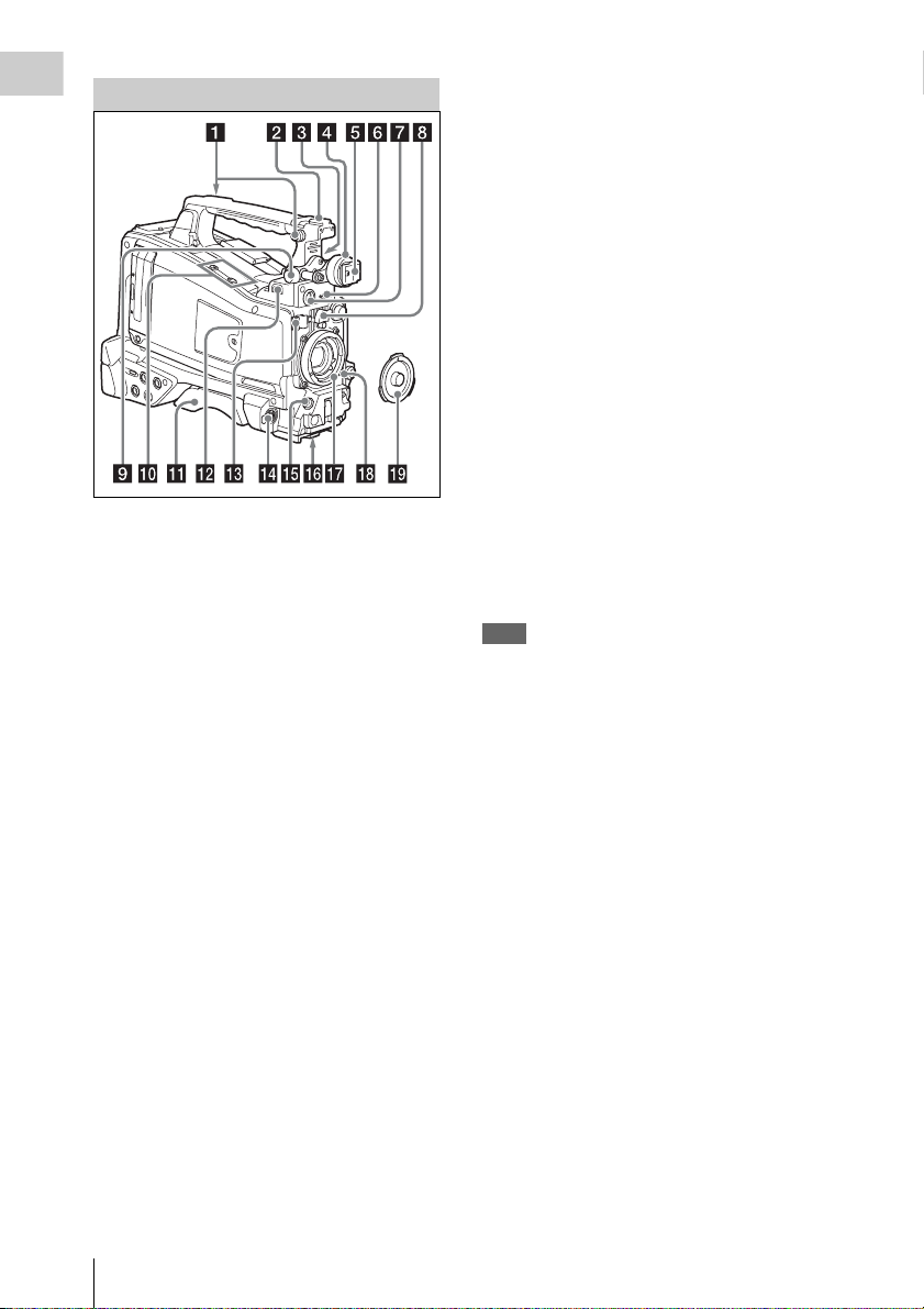
Accessory Attachments
Chapter 1 Overview
i Viewfinder front-to-back positioning
knob (LOCK knob) (see page 30).
j Fitting for optional microphone holder
(see page 39).
k Shoulder pad
Raise the shoulder pad fixing lever to adjust the
position in the front-to-rear direction (see
page 43).
l LIGHT (video light) connector (2-pin,
female)
A video light with a maximum power
consumption of 50 W, such as the Anton Bauer
Ultralight 2 or equivalent can be connected (see
page 42).
m Lens cable clamp
a Shoulder strap fitting (see page 42).
b Accessory fitting shoe (see page 42).
c Viewfinder front-to-back positioning
lever
d Viewfinder left-to-right posi tioning ring
(see page 30).
e Viewfinder fitting shoe
f VF (viewfinder) connector (26-pin,
rectangular)
g VF (viewfinder) connector (20-pin,
round)
Connect the cable of the optional DXF-51 or
DXF-20W viewfinder.
For connecting the DXF-51, optional parts are
required. Consult a Sony service representative for
information about connecting the DXF-51.
h Lens mount securing rubber
After locking the lens in position using the lens
locking lever, fit this rubber over the lower of the
two projections. This fixes the lens mount,
preventing it from coming loose.
n MIC IN (microphone input) (+48 V)
connector (XLR type, 5-pin, female)
The power (+48 V) is supplied via this connector.
o LENS connector (12-pin)
Note
When connecting or disconnecting the lens cable
to this connector, power off the camcorder first.
p Tripod mount
q Lens mount (special bayonet mount)
Consult a Sony service representative for
information about available lenses.
r Lens locking lever
After inserting the lens in the lens mount, rotate
the lens mount ring with this lever to lock the lens
in position.
After locking the lens, be sure to use the lens
mount securing rubber to prevent the lens from
becoming detached.
s Lens mount cap
Remove by pushing up the lens locking lever.
When no lens is mounted, keep this cap fitted for
protection from dust.
Locations and Functions of Parts and Controls
12

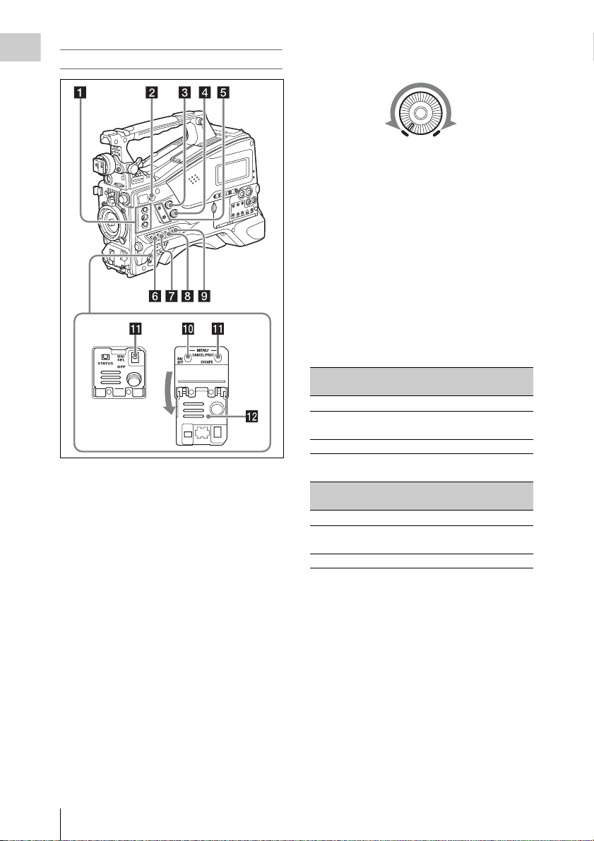
Operating and Connectors Section
Front
a REC START (recording start) button
The effect is the same as that of the REC button
on the lens.
b SHUTTER switch
Set to ON to use the electronic shutter. Push to
SELECT to switch the shutter speed or shutter
mode setting. When this switch is operated, the
new setting appears on the viewfinder screen for
about three seconds.
For details, see
“Setting the Electronic Shutter” (page 50).
Note
When shutter is set to on while the flashband
reduce function is set to on, the flashband reduce
function is set to off and the FBR indication on
the display disappears. When shutter is set to off,
the flashband reduce function is set to on and the
FBR indication appears on the display.
c FILTER selector
When this selector is used, the new setting
appears on the viewfinder screen for about three
seconds.
FILTER selector
setting
1 CLEAR
ND filter
FILTER selector
setting
2
3
4
ND filter
1
/4 ND (attenuates light to
approximately
1
/16 ND (attenuates light to
approximately
1
/64 ND (attenuates light to
approximately
1
/4)
1
/16)
1
/64)
You can change the “MAINTENANCE” menu
setting so that different white balance settings can
be stored for different FILTER selector positions.
This allows you to automatically obtain optimum
white balance for the current shooting conditions
in linkage with the filter selection.
For details, see “Adjusting the White Balance”
(page 48).
d MENU knob
Changes the item selection or a setting within the
menu (see page 110).
e AUTO W/B BAL (automatic white/
black balance adjustment) switch
WHITE: Adjust the white balance automatically.
If the WHITE BAL switch (see page 15) is
set to A or B, the white balance setting is
stored in the corresponding memory. If the
WHITE BAL switch is set to PRST, the
automatic white balance adjustment function
does not operate.
BLACK: Adjust the black set and black balance
automatically.
You can use the AUTO W/B BAL switch even
when the ATW (Auto Tracing White Balance)
function is operating.
If you push the switch to the WHITE side once
more during the automatic white balance
adjustment, the adjustment is cancelled and the
white balance setting returns to the original
setting.
If you push the switch to the BLACK side once
more during the automatic black balance
adjustment, the adjustment is cancelled and the
black balance setting returns to the original
setting.
f MIC (microphone) LEVEL control (see
page 55).
Chapter 1 Overview
Locations and Functions of Parts and Controls
13
Right side (near the front)
Chapter 1 Overview
“Set,” the alarm tone is audible even when this
volume control is at the minimum position.
ALARM
a ASSIGN. (assignable) 1/2/3 switches
You can assign the desired functions to these
switches on “OPERATION” > “Assignable SW”
in the setup menu (see page 158).
The ASSIGN.1/3 switches are provided with an
indicator to show whether a function is assigned
to the switch (ON) or not (OFF).
b COLOR TEMP. (color temperature)
button
You can also use this button as an assignable
switch (see page 158).
c ALARM (alarm tone volume
adjustment) knob
Controls the volume of the warning tone that is
output via the built-in speaker or optional
earphones. When the knob is turned to the
minimum position, no sound can be heard.
However, if “MAINTENANCE” > “Audio” >
“Min Alarm Volume” in the setup menu is set to
Minimum
Maximum
d MONITOR (monitor volume
adjustment) knob
Controls the volume of the sound other than the
warning tone that is output via the built-in speaker
or earphones. When the knob is turned to the
minimum position, no sound can be heard.
e MONITOR (audio monitor selection)
switches
By means of combinations of the two switches,
you can select audio that you want to hear through
the built-in speaker or earphones.
Position of down-side switch: CH-1/2
Position of up-side
switch
CH-1/CH-3 Channel 1 audio
MIX Channels 1 and 2 mixed
CH-2/CH-4 Channel 2 audio
Audio outp ut
audio (stereo)
a)
Position of down-side switch: CH-3/4
Position of up-side
switch
CH-1/CH-3 Channel 3 audio
MIX Channels 3 and 4 mixed
CH-2/CH-4 Channel 4 audio
a) By connecting stereo headphones to the EARPHONE
jack, you can hear the audio in stereo. (Under
“MAINTENANCE” > “Audio” in the setup menu,
“Headphone Out” must be set to “Stereo.”)
Audio outp ut
audio (stereo)
a)
f ASSIGN. (assignable) 0 switch
You can assign the desired function to this switch
on “OPERATION” > “Assignable SW” in the
setup menu (see page 159).
This is a momentary type switch. Each press of
the switch turns the function assigned to this
switch on or off.
Locations and Functions of Parts and Controls
14

g GAIN selector
Switches the gain of the video amplifier to match
the lighting conditi ons during shooting. The gains
corresponding to the L, M, and H settings can be
selected on “OPERATION” > “Gain Switch” in
the setup menu (see page 121).
When this switch is adjusted, the new setting
appears on the viewfinder screen for about three
seconds.
h OUTPUT/DCC (output signal/dynamic
contrast control) switch
BARS: Output the color bar signal.
CAM: Output the video signal being shot. When
this is selected, you can switch DCC
1)
on and
off.
1) DCC (Dynamic Contrast Control): Against a very
bright background with the iris opening adjusted to the
subject, objects in the background will be lost in the
glare. The DCC function will suppress the high
intensity and restore much of the lost detail and is
particularly effective in the following cases.
• Shooting people in the shade on a sunny day
• Shooting a subject indoors, against a background
through a window
• Any high contrast scene
i WHITE BAL (white balance memory)
switch
PRST: Adjust the color temperature to the preset
value (the factory default setting: 3200K).
Use this setting when you have no time to
adjust the white balance.
A or B: Recall the white balance adjustment
settings already stored in A or B. Push the
AUTO W/B BAL switch (see page 13) on
the WHITE side, to automatically adjust the
white balance, and save the adjustment
settings in memory A or memory B.
1)
B (ATW
): When this switch is set to B and
“OPERATION” > “White Setting” > “White
Switch<B>” is set to “ATW” in the setup
menu, ATW is activated.
You can use the AUTO W/B BAL switch
even when ATW is in use.
When this switch is adjusted, the new setting
appears on the viewfinder screen for about three
seconds.
1) ATW (Auto Tracing White Balance): The white
balance of the picture being shot is adjusted
automatically for varying lighting conditions.
j MENU ON/OFF switch
This switch is used to display the menu on the
viewfinder screen or the test signal screen. Each
time the switch is pushed down, the menu screen
is turned on and off.
The function of this switch is the same as that of
the MENU button in the thumbnail screen
operations section.
k STATUS ON/SEL/OFF (menu display
on/page selection/display off) switch
MENU CANCEL/PRST (preset) /
ESCAPE switch
When the menu is not displayed, this switch
functions as the STATUS ON/SEL/OFF switch.
When the menu is displayed, the switch functions
as the MENU CANCEL/PRST/ESCAPE switch.
(To use the MENU CANCEL/PRST/ESCAPE
switch, open the cover.)
Use the STATUS ON/SEL/OFF switch in the
following way.
ON/SEL: Each time this switch is pushed
upward, a window to confirm the menu
settings and status of the camcorder appears
on the viewfinder screen (see page 59). Each
page is displayed for about 10 seconds.
To clear the page immediately after display,
OFF:
push this switch down to the OFF position.
Use the MENU CANCEL/PRST/ESCAPE
switch in the following way.
CANCEL/PRST: Pushing this switch up to this
position after a setting is changed in the setup
menu displays the message to confirm
whether the previous settings are cancelled.
Pushing this switch up to this position again
cancels the previous settings.
Pushing this switch up to this position before
a setting is changed in the setup menu or after
a setting change is cancelled in the setup
menu displays the message to confirm
whether the setting is reset to the initial
value.
Pushing this switch up to this position again
resets the settings to the initial value.
ESCAPE: Use this switch when the menu page,
which has a hierarchical structure, is opened.
Each time the switch is pushed to this
position, the page returns to one stage higher
in the hierarchy.
l Cover
Chapter 1 Overview
Locations and Functions of Parts and Controls
15

Right side (near the rear)
Chapter 1 Overview
a Built-in speaker
The speaker can be used to monitor E-E1) sound
during recording, and playback sound during
playback. The speaker also sounds alarms to
reinforce visual warnings (see page 178).
If you connect earphones to the EARPHONE
jack, the speaker output is suppressed
automatically.
1) E-E: Abbreviation of “Electric-to-Electric”. In E-E
mode, video and audio signals input to the camcorder
are output after passing through internal electric
circuits only. This can be used to check input signals.
b Monochrome LCD panel
Displays remaining battery capacity, remaining
media capacity, audio levels, time data, and so on
(see page 21).
c WARNING indicator (see page 178).
d ACCESS lamp
Lights up in blue when data is written to or read
from the recording media.
e Protection cover of the audio control
section (see page 17).
f Protection cover of the thumbnail
screen operations section (see page 17).
g F REV (fast reverse) button and
indicator
The playback speed changes in the order ×4 t
×15 t ×24 with each press of the button. The
indicator lights during high-speed playback in the
reverse direction.
h PLAY/PAUSE button and indicator
Press this button during playback to pause,
outputting a still image. At this time the indicator
flashes at a rate of once per second.
Pressing the F REV or F FWD button during
playback or pause starts high speed playback in
the forward or reverse direction.
i F FWD (fast forward) button and
indicator
The playback speed changes in the order ×4 t
×15 t ×24 with each press of the button. The
indicator lights during high-speed playback in the
forward direction.
j PREV button
This jumps to the first frame of the current clip.
If you press this together with the F REV button,
the jump is to the first frame of the first recorded
clip on the recording media.
If you press this button twice in rapid succession,
the jump is to the first frame of the last preceding
clip (or the first frame of the current clip when no
preceding clips exist).
k STOP button
l NEXT button
This jumps to the first frame of the next clip.
If you press this together with the F FWD button,
the jump is to the first frame of the last recorded
clip on the recording media.
Locations and Functions of Parts and Controls
16
m EXPAND (expand function) button
If you press this button when the thumbnail
screen is displayed, the duration of the selected
clip is divided into fractions, and the first frame of
each of the divisions is shown in a further
thumbnail display (expand function). For an HD
recorded MP4 clip, its duration is divided into 12.
If an SD recorded AVI clip comprises multiple
files, the divisions are displayed for the individual
files.
For MP4 clips, each time you press this button the
division is repeated. Hold down the SHIFT button
and press this button to step back through the
division process.
n HOLD (display hold) button
Pressing this button instantly freezes the time data
displayed in the monochrome LCD panel. (The
timecode generator continues running.) Pressing
this button again releases the hold.
For details of the counter display, see page 21.
o RESET/RETURN button
Resets the value shown in the time counter
display in the monochrome LCD panel.
According to the settings of the PRESET/
REGEN/CLOCK switch (see page 18) and the
F-RUN/SET/R-RUN switch (see page 18), this
button resets the display as follows.
Settings of switches To r eset
DISPLAY switch:
COUNTER
DISPLAY switch:
TC
PRESET/REGEN/
CLOCK switch:
PRESET
F-RUN/SET/R-RUN
switch: SET
DISPLAY switch:
U-BIT
PRESET/REGEN/
CLOCK switch:
PRESET
F-RUN/SET/R-RUN
switch: SET
a) Of the timecode bits for every frame recorded on the
media, those bits which can be used to record useful
information for the user such as scene number,
shooting place, etc.
For details, see “Setting the Time Data” (page 56).
Counter to 0:00:00:00
Timecode to 00:00:00:00
User bits data
00
a)
to 00 00 00
This button returns to the previous screen when
pressed during thumbnail screen display, expand
thumbnail screen display, or shot mark thumbnail
screen display.
p DISPLAY switch
This cycles the data displayed in the time counter
display in the monochrome LCD panel through
the sequence COUNTER, TC, and U-BIT (see
page 21).
COUNTER: Display the elapsed recording/
playback time (hours, minutes, seconds,
frames).
TC: Display timecode.
U-BIT: Display user bits data.
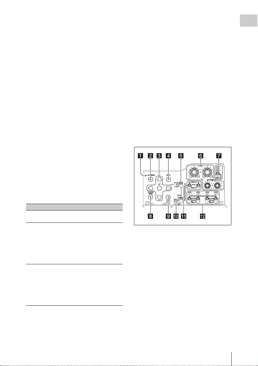
q BACKLIGHT button
Thumbnail screen operations section and audio
control section
a THUMBNAIL indicator
This lights when thumbnail screen is displayed.
b THUMBNAIL button
Press this button to display the thumbnail screen
(see page 96) and to carry out a thumbnail
operation.
Press once more to return to the original display.
c SET (set) button and arrow buttons
Use these buttons to make timecode and user bit
settings, and for thumbnail screen operations (see
page 102).
When the menu is displayed, press this button to
select an item or to confirm the setting change.
Chapter 1 Overview
Locations and Functions of Parts and Controls
17

d MENU button
Each press of this button turns the setup menu
Chapter 1 Overview
display on and off.
The function of this button is the same as that of
the MENU ON/OFF switch.
e F-RUN/SET/R-RUN (free run/set/
recording run) switch
Selects the operating mode of the internal
timecode generator. The operating mode is set as
explained below, depending on the position of the
switch.
F-RUN: Timecode keeps advancing, regardless
of whether the camcorder is recording. Use
this setting when synch ronizing the timecode
with external timecode.
SET: Sets the timecode or user bits.
R-RUN: Timecode advances only during
recording. Use this setting to have a
consecutive timecode on the recording
media.
For details, see “Setting the Timecode” (page 56)
and “Setting the User Bits” (page 57).
f LEVEL CH1/CH2/CH3/CH4 (audio
channel 1/2/3/4 recording level) knobs
Adjust the audio levels to be recorded on channels
1, 2, 3, and 4 when the AUDIO SELECT CH1/
CH2 and AUDIO SELECT CH 3-4 switches are
set to MANUAL.
g AUDIO SELECT CH 3-4 (audio
channel 3/4 adjustment method
selection) switch
Select the audio level adjustment method for each
of audio channels 3 and 4.
AUTO : Automatic adjustment
MANUAL: Manual adjustment
h ESSENCE MARK button
By pressing this button when the thumbnail
display of a clip is on the screen, you can view the
following thumbnail display of the shot-marked
frames of that clip, depending on the item
selected in a list displayed on the screen.
All: Thumbnail display of all frames marked with
essence marks.
Shot Mark1: Thumbnail display of the frames
marked with Shot Mark 1
Shot Mark2: Thumbnail display of the frames
marked with Shot Mark 2
You can also select Shot Mark 0 and Shot Mark 3
to Shot Mark 9.
If you have recorded clips by using planning
metadata that defined names for Shot Mark 0 to
Shot Mark 9, the defined names are displayed
instead of the above item names in the list.
i SHIFT button
Use this in combination with other buttons.
j PRESET/REGEN (regeneration)/
CLOCK switch
Selects the type of timecode to record.
PRESET: Record new timecode on the media.
REGEN: Record timecode continuous with the
existing timecode recorded on the media.
Regardless of the setting of the F-RUN/SET/
R-RUN switch, the camcorder operates in RRUN mode.
CLOCK: Record timecode synchronized to the
internal clock. Regardless of the setting of
the F-RUN/SET/R-RUN switch, the
camcorder operates in F-RUN mode.
k AUDIO SELECT CH1/CH2 (audio
channel 1/2 adjustment method
selection) switches
Select the audio level adjustment method for each
of audio channels 1 and 2.
AUT O: Automatic adjustment
MANUAL: Manual adjustment
l AUDIO IN CH1/CH2/CH3/CH4 (audio
channel 1/2/3/4 input selection) switches
Select the audio input signals to be recorded on
audio channels 1, 2, 3 and 4.
FRONT: Audio input signals from the
microphone connected to the MIC IN
connector
REAR: Audio input signals from an audio device
connected to the AUDIO IN CH-1/CH-2
connectors
WIRELESS: Audio input signals from the UHF
portable tuner if it is installed
Locations and Functions of Parts and Controls
18
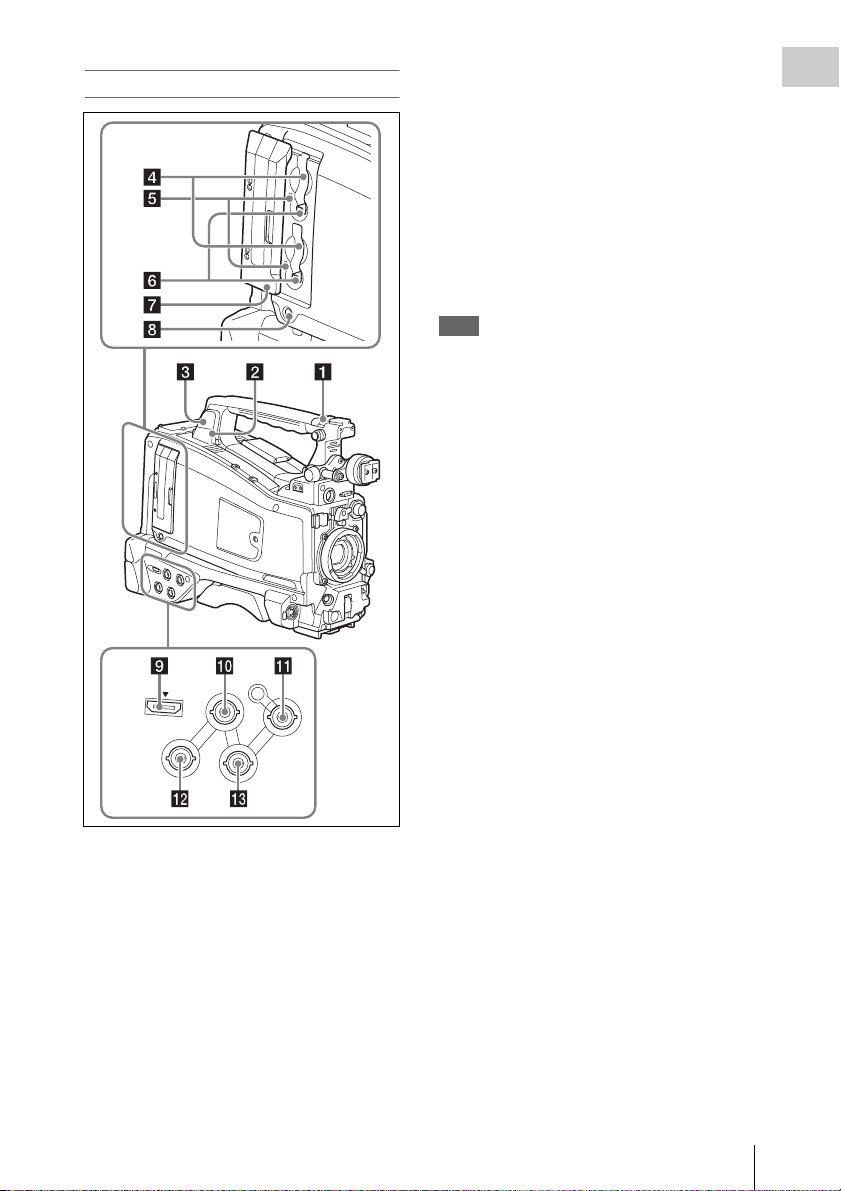
Left side and upper section
c External device connector
Connect an optional CBK-WA01 Wi-Fi Adapter,
CBK-WA101 Wireless Adapter, IFU-WLM3
USB Wireless LAN Module, or USB flash drive.
When connecting the CBK-WA01/CBK-
WA101/IFU-WLM3: You can connect the
camcorder and computer via Wi-Fi
connection (wireless connection).
When connecting a USB flash drive: You can
record, store, or load the following data.
• Planning metadata (see page 93)
• Setting data file (see page 163)
Note
Use this connector only for connecting the CBK-WA01,
CBK-WA101, IFU-WLM3, USB flash drive, or USB
media. Do not connect and use a USB hub or similar
products.
For details on Wi-Fi connection, refer to “Using WiFi Connection” (page 79).
d SxS memory card slots
These two slots (A and B) can receive SxS
memory cards or other recording media (see
page 60).
e ACCESS lamps
Indicate the state of slots A and B (see page 60).
You can check whether the lamps are lit even
when the slot cover is closed.
Chapter 1 Overview
H
D
M
I
G
E
N
L
O
C
K
IN
T
C
IN
V
ID
E
O
O
U
T
T
C
O
U
T
a ASSIGNABLE 4/5 switches
You can assign the desired functions to these
switches on “OPERATION” > “Assignable SW”
in the setup menu (see page 159).
Off is assigned to these switches when the
camcorder is shipped from the factory.
b PC connector
Used to put this camcorder into USB connection
mode and use it as an external storage device for
a computer. When a computer without
ExpressCard slot is connected to this connector,
every memory card inserted in the camcorder is
recognized as a drive for that computer.
f EJECT buttons (see page 60)
g Slot cover
Slide to the left and right to open and close.
h SLOT SELECT (SxS memory card
select) button (see page 61).
i HDMI
1)
output connector
When a video monitor provided with an HDMI
signal input connector is connected to this
connector, you can monitor picture being shot
(camera picture) or playback picture.
1) The terms HDMI and HDMI High-Definition
Multimedia Interface, and the HDMI Logo are
trademarks or registered trademarks of HDMI
Licensing LLC in the United States and other
countries.
Locations and Functions of Parts and Controls
19

j GENLOCK IN (genlock signal input)
Chapter 1 Overview
connector (BNC type)
This connector inputs a reference signal when the
camcorder is to be genlocked or when timecode is to
be synchronized with external equipment. Available
reference signals vary depending on the current
system frequency as shown in the following table.
System frequency Available reference signals
1080/59.94i 1080/59.94i, 480/59.94i
1080/29.97P 1080/59.94i, 480/59.94i
1080/23.98P (PsF
output)
1080/23.98P
(Pulldown output)
720/59.94P 1080/59.94i, 720/59.94P,
720/29.97P 1080/59.94i, 720/59.94P,
720/23.98P 1080/59.94i, 720/59.94P,
480/59.94i 1080/59.94i, 480/59.94i
480/29.97P 1080/59.94i, 480/59.94i
1080/50i 1080/50i, 576/50i
1080/25P 1080/50i, 576/50i
720/50P 1080/50i, 720/50P, 576/50i
720/25P 1080/50i, 720/50P, 576/50i
576/50i 1080/50i, 576/50i
576/25P 1080/50i, 576/50i
1080/23.98PsF, 480/59.94i
1080/59.94i, 480/59.94i
480/59.94i
480/59.94i
480/59.94i
(Genlock for the camera module supports
horizontal sync signals only.) Adjust the genlock
H-phase (phase of horizontal sync signal) on
“MAINTENANCE” > “Genlock” in the setup
menu.
k TC IN (timecode input) connector
(BNC type)
To apply an external lock to the timecode of the
camcorder, input the reference timecode.
For details, see “Setting the Timecode” (page 56).
l VIDEO OUT connector (BNC type)
The output signals can be selected either
composite video or HD-Y depending on the
setting of “OPERATION” > “Input/Output” >
“Output&i.LINK” in the setup menu.
m TC OUT (timecode output) connector
(BNC type)
To lock the timecode of an external VTR to the
timecode of this camcorder, connect this connector
to the external VTR’s timecode input connector.
Rear
a TALLY (back tally) indicators (red)
Light up during recording. They will not light if
the TALLY switch is set to OFF. These indicators
also flash to indicate warnings (see page 16). The
tally indicator on the front of the viewfinder and
the REC indication on the viewfinder screen light
or flash in the same manner.
For details, see “Operation Warnings” (page 178).
b TALLY switch
Set to ON to activate the TALLY indicator
function.
c EARPHONE jack (stereo, minijack)
You can monitor the E-E sound during recording
and playback sound during playback. When an
alarm is indicated, you can hear the alarm sound
through the earphone. Plugging an earphone into
the jack automatically cuts off the built-in
speaker.
You can select monaural or stereo on
“MAINTENANCE” > “Audio” in the setup
menu.
Locations and Functions of Parts and Controls
20

d AUDIO IN selectors
Select the audio source you connect to the
AUDIO IN CH-1/CH-2 connectors.
LINE: When connecting a stereo amplifier or
other external audio signal source
MIC: When connecting a microphone that does
not require 48 V power supply
+48V: When connecting a microphone that
requires 48 V power supply
e
HD/SD SDI OUT connectors (BNC type)
The PMW-400 has two HD/SD SDI OUT
connectors. These connectors output an HDSDI
or SDSDI signal (with embedded audio). The
output from these connectors can be turned on or
off, on “OPERATION” > “Input/Output” > “SDI
Output” in the setup menu.
f AUDIO IN CH-1/CH-2 (audio channel
1 and channel 2 input) connectors (XLR
type, 3-pin, female)
You can connect audio equipment or a
microphone.
g Bottom cover
This is provided for protecting the cables
connected to the connectors on the rear panel.
By loosening the screws which retain the cover to
the bottom of the camcorder, you can adjust the
position of the cover depending on the size and
shape of the microphone or audio cable plugs.
After adjusting the position, tighten the screws to
secure the cover.
h AUDIO OUT connector (XLR type, 5-
pin, male)
Outputs the audio signals recorded on audio
channels 1 and 2 or audio channels 3 and 4. The
audio signals are selected by the MONITOR
switch.
i REMOTE connector (8-pin)
Note
Before connecting/disconnecting the Remote Control
Unit to/from the camcorder, be sure to turn off the
camcorder POWER switch.
j i.LINK (HDV/DV) connector (6-pin,
IEEE1394 compliant, S400)
To input and output HDV /DV streams, connect to
an HDV/DV device.
Monochrome LCD Panel
a Timecode status
NDF: Appears when non-drop-frame timecode is
selected.
EXT-LK: Appears when the internal timecode
generator is locked to an external signal input
to the TC IN (timecode input) connector.
b Counter display mode
Shows the type of information selected by the
DISPLAY switch to be displayed in the time
counter display.
COUNTER: Counter values
TC: Timecode
U-BIT: User bits data
c Time counter display
Switches displays of time counter values,
timecode, and user bits data, depending on the
position of the DISPLAY switch.
When the HOLD button is pressed to hold the
timecode value, the timecode is displayed in the
format shown below. When the HOLD button is
pressed again to release the hold, the timecode is
displayed in the normal format.
The three dots indicates that timecode is
displayed in the hold mode.
d HOLD indication
Appears when the timecode generator output is
displayed in the hold mode.
e Audio level indicators
Indicate the audio recording or playback levels of
channels 1 to 4.
Chapter 1 Overview
Locations and Functions of Parts and Controls
21
f Lock icon
Appears when the recording media is write-
Chapter 1 Overview
protected.
g Remaining media capacity indicator
Shows bar segments indicating the remaining
capacity of recording media in the slots.
h Remaining battery capacity indicator
Shows bar segments indicating the remaining
battery capacity.
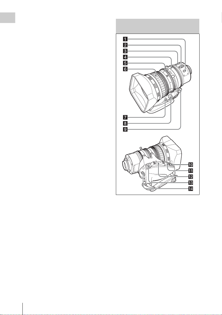
Auto Focus Lens (Supplied with the PMW-400K)
Locations and Functions of Parts and Controls
22
a PUSH AF (auto focus) button
When the focus adjustment is in the manual mode,
by pressing this button you can use the auto focus
for an instantaneous adjustment to the subject.
When the button is pressed, the auto focus
operates until the image is in focus, then
disengages.
Even when the FOCUS switch is set to A (auto),
by pressing this button, you can restart the auto
focus.
b FOCUS switch
A (auto): The auto focus function is constantly
active. Even with the switch in the A
position, you can manually adjust the focus
by operating the focus ring.
M (manual): The manual mode allows focusing
adjustment with the focus ring.

In manual mode, auto focus adjustment is also
possible, by pressing the PUSH AF button.
c MACRO switch
When this switch is in the ON position, the macro
mode is enabled, allowing focusing over the whole
range (5 cm
(from 5 cm
This operation is independent of whether the
focus adjustment mode is auto or manual.
In the macro range, the auto focusing speed is
lower.
1) At the wide-angle setting
1)
to ∞ ) including the macro range
1)
to 90 cm from the front of the lens).
d Iris ring
For manual iris adjustment, set the IRIS switch to
the M (manual) position, then turn this ring.
e Zoom ring
For manual zoom adjustment, set the ZOOM
switch to the MANUAL position, then turn this
ring.
f Focus ring
Turn this ring to adjust the focus.
This ring can be turned endlessly in both
directions. The faster you turn, the faster the
focusing mechanism operates, to minimize the
amount of turning required for focusing.
When you slide the focus ring back (toward the
camcorder), the focus mode becomes Full MF
mode (see page 54).
g Flange focal length adjustment button
Press this to adjust the flange focal length (the
distance from the lens mounting flange plane to
the focusing plane) (see page 36).
h Zoom control connector (8-pin)
Connecting an optional zoom servo controller
allows remote control of zooming.
i ZOOM switch
SERVO: Motorized zoom. Operate the zoom
with the power zoom lever.
MANUAL (manual): Manual zoom. Operate the
zoom with the zoom ring.
j PUSH AUTO button
When the IRIS switch is in the M position for manual
adjustment, press this button for an instantaneous auto
adjustment. The iris is automatically adjusted while
the button is held down.
k IRIS switch
A (auto): The iris is adjusted automatically.
M (manual): Adjust the iris with the iris ring.
l Power zoom lever
This is enabled when the ZOOM switch is in the
SERVO position. Press the W end for wide-angle
and the T end for telephoto.
Press the lever harder for a faster zoom action.
Notes on auto focus
• In the following cases, it may be difficult to
focus on the subject. If this does happen, use
manual focusing.
- If the subject has no contrast
- If the subject is moving rapidly
- When shooting point light sources, under
street lighting or at night
- When there are very bright objects close to the
subject
- When shooting through a glass window
• If there are a number of objects within the
screen at close and far range, the focus may not
be on the intended subject. In this case, with the
subject on which you want to focus in the center
of the screen, press the PUSH AF button.
• After focusing with the PUSH AF button, if you
operate the zoom or adjust the iris, the depth of
field may become shallower, losing crisp focus.
In such cases, press the PUSH AF button once
more.
• If you focus at wide-angle then zoom to
telephoto, the subject may no longer be in focus.
• It may take time until the image is in focus
while using the slow shutter mode.
Note on zoom speed
Depending on the shooting distance, the zoom
speed may fall as the lens approaches the
telephoto end.
m RET (return video) button
You can use this as an assignable switch (see
page 162).
Use this to check the video when Lens RET is
assigned to this button (factory default setting). If
you press this after recording stops, the last few
seconds recorded appear on the viewfinder screen
(recording review) (see page 84).
Pressing this button (single click) during
recording or playback records a Shot Mark 1
mark, and double-clicking records a Shot Mark 2
mark (see page 86).
Chapter 1 Overview
Locations and Functions of Parts and Controls
23
n VTR button
Use this to start and stop recording. Press once to
Chapter 1 Overview
start recording, then press once more to stop.
VTR button on the lens, or the VTR button on the
remote control unit.
When an abnormality occurs, the tally indicator
flashes to indicate a warning.
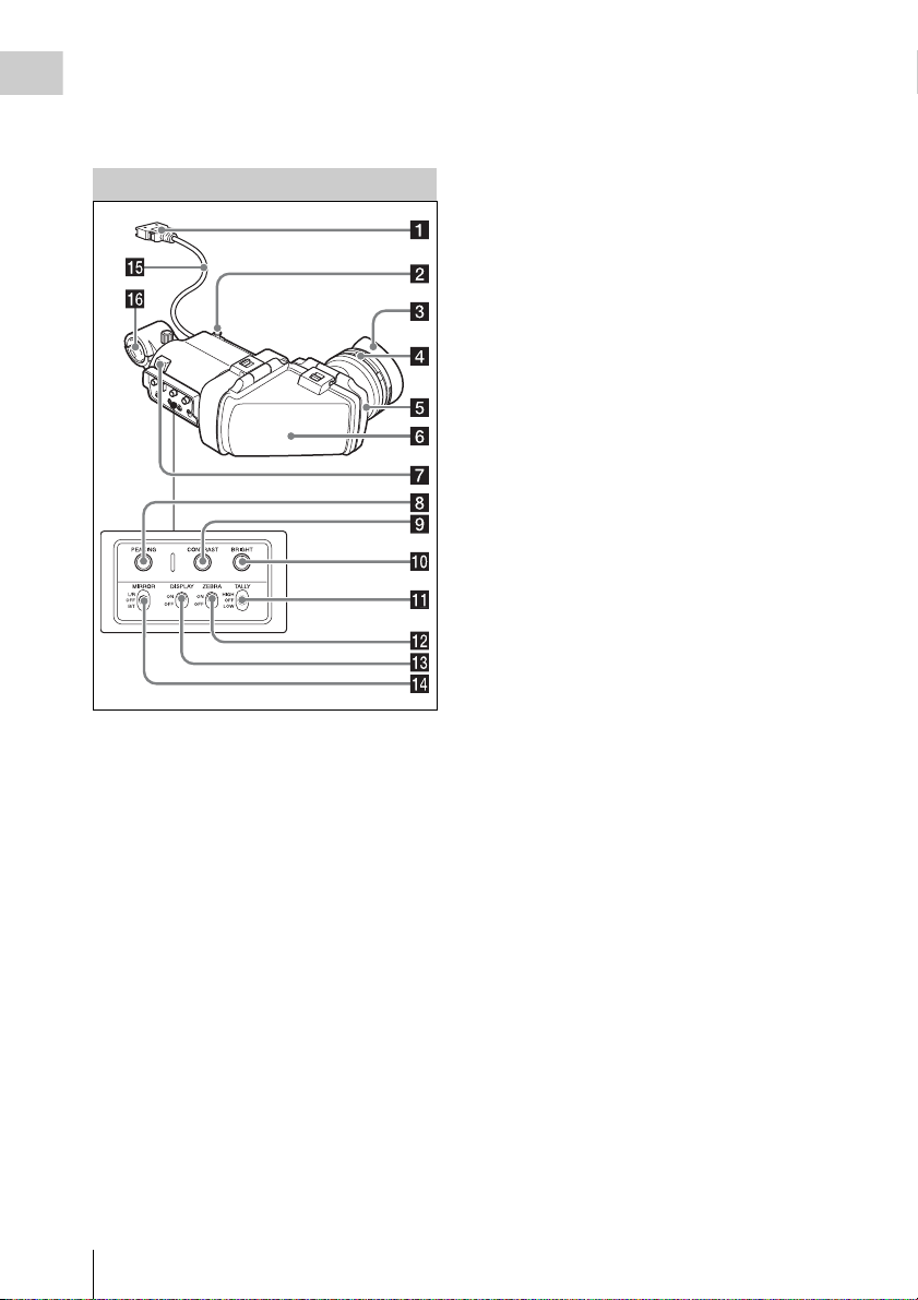
Viewfinder
a Plug
Connect to the VF connector (26-pin) on the
camcorder.
b Stopper
Prevents the viewfinder from coming off the
camcorder when it is slid from side to side.
c Eyecup
d Diopter adjustment ring
Allows for optimal focus adjustment.
e Eyepiece
You can raise this up when required by the situation.
f Viewfinder barrel
You can raise this up or rotate when required by
the situation.
g Tally indicator
Lights up when recording is started by a press of
the REC START button on this camcorder, the
h PEAKING control
Turning this control clockwise adjusts the picture
sharpness, and makes focusing easier. This
control has no effect on the output signals of the
camcorder.
i CONTRAST control
Adjusts the contrast of the screen. This control
has no effect on the output signals of the
camcorder.
j BRIGHT control
Adjusts the brightness of the screen. This control
has no effect on the output signals of the
camcorder.
k TALLY switch
Controls the tally indicator located on the front of
the viewfinder.
HIGH: The tally indicator brightness is set to
high.
OFF: The tally indicator is disabled.
LOW: The tally indicator brightness is set to low.
l ZEBRA (zebra pattern) switch
Controls the zebra pattern display on the
viewfinder screen as follows.
ON: Display a zebra pattern.
OFF: Do not display a zebra pattern.
m DISPLAY switch
ON: Display text information.
OFF: Do not display text information.
n MIRROR switch
The image display on the monitor screen becomes
reversed horizontally or vertically when the
viewfinder barrel is raised up or rotated. Use this
switch to control the image display in such
situation.
L/R: Reverse the image horizontally.
OFF: Do not reverse the image.
B/T: Reverse the image vertically.
o Viewfinder cable
p Microphone holder
Locations and Functions of Parts and Controls
24
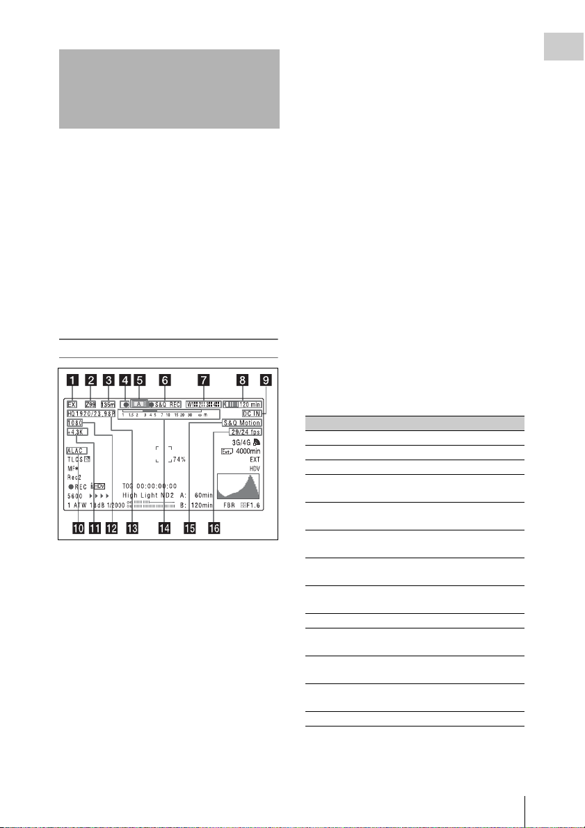
Viewfinder Screen Display
The viewfinder screen displays not only the video
picture but also characters and messages
indicating the camcorder settings and operating
status, a center marker, a safety zone marker, etc.
When the menu screen is not displayed and the
DISPLAY switch is set to ON, the items for
which an ON setting was made with
“OPERATION” > “Super Impose” in the setup
menu or with related switches are displayed at the
top and bottom of the screen.
Not only these indications are displayed on the
viewfinder screen, but a menu setting enables
them to be output as video signals.
b Zoom position (when the lens is
mounted)
Indicates the zoom position of the zoom lens in
the range from 0 to 99.
c Focus position (when the serial lens is
mounted)
Indicates the focus position as distance to the
subject (in units of m).
d Green tally
Lights when the camcorder is the following
states.
• “MAINTENA NCE” > “Camera Config” > “HD
SDI Remote I/F” is set to “G-Tally” in the setup
menu and a recording control signal is output
from the HD/SD SDI OUT connector.
• Green tally signal received (when a camera
adaptor is mounted on the camcorder and a
camera control unit is connected)
Chapter 1 Overview
Top of viewfinder screen
a Extender settings
Indicates the setting of the digital extender
function (when optional CBK-CE01 is installed)
of this camcorder and the setting of the lens
extender.
EX: The lens extender is on.
08: The lens shrinker is on.
x2D: The digital extender function of this
camcorder is on.
Ex2D: The lens extender and the digital extender
function of this camcorder are both on.
Digital extender function can be turned on or off
by an assignable sw itch to which Digi tal Extender
is assigned.
e Media status
Displays the name of the currently active media
slot (A or B).
f Recording mode/operation status
Indication Meaning
zREC Recording in progress
STBY Standby for recording
zCACHE Standby in Picture Cache mode
zINT REC Recording in progress in Interval
zINT STBY Standby for next recording in
INT STBY Standby in Interval Recording
zFRM REC Recording in progress in Frame
zFRM
STBY
FRM STBY Standby in Frame Recording mode
zS&Q REC Recording in progress in Slow &
S&Q STBY Standby in Slow & Quick Motion
zCALL Being called from a connected
BREVIEW During recording review
Recording mode
Interval Recording mode
mode
Recording mode
Standby for next recording in
Frame Recording mode
Quick Motion mode
mode
device
Viewfinder Screen Display
25

g Wireless receiver reception level
When a wireless receiver is installed in the
Chapter 1 Overview
camcorder, “W” appears together with four
segment reception level indicators for each of the
channels (1 to 4) that can be used by the receiver.
The indications are as follows.
In normal situation: The number of white
segments indicates the strength of the signal
level.
Muting (for an analog receiver) or error rate
aggravation (for a digital receiver): The
number of gray segments indicates the
strength of the signal level.
Reception level over peak: “P” is displayed
instead of the indicators.
1)
Tuner battery is low: The channel number and
indicator of the corresponding channel
1)
flash.
1) When an optional DWR-S01D is used
h Battery remaining/voltage capacity
Type of power
source
InfoLithium
battery
Anton Bauer
battery
Other type than
above
What is displayed
Remaining battery capacity icon
and remaining recording time
Remaining battery capacity (%
indication)
Input voltage
i External power input
Appears when power is supplied from an external
power source connected to the DC IN connector.
j ALAC (magnification chromatic
aberration correction) status
Appears when “ALAC” (see page 144) of the
MAINTENANCE menu is set to “AUTO,” and
an ALAC compatible lens is attached to the
camcorder.
l Number of system lines
Indicates the number of system lines (1080/720/
576/480) of video currently being recorded or
played back.
m Video format
Indicates the video format (see page 44).
The video aspect ratio (16:9 or 4:3) can also be
displayed when the recording format is set to
DVCAM.
n Depth of field indication (when the
serial lens is mounted)
Error/warning indication
A bar indicates the depth of field. The display unit
is meters or feet, as selected on “OPERATION”
> “Display On/Off” > “Lens Info” in the setup
menu.
An error or warning message is displayed here
depending on the situation.
Under this area, you can also display the name of
the next clip to be recorded (see page 129).
o Special recording mode indication
The following is displayed when the camcorder is
in a special recording mode.
• Frame Rec (Frame Recording mode)
• Interval Rec (Interval Recording mode)
• S&Q Motion (Slow & Quick Motion mode)
p Special recording mode settings
indication
Appears when the camcorder is in a special
recording mode.
k Color temperature
Displays a color temperature calculated from the
gain of R and B, in the range 1.5 K to 50.0 K (in
steps of 0.1 K). The +/– signs may be displayed
depending on the “Offset White” setting (see
page 126).
No display: “Offset White” is “Off.”
+: The value of “Offset White” is greater than
3200K.
–: The value of “Offset White” is less than
3200K.
Viewfinder Screen Display
26
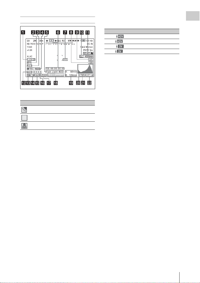
Bottom of viewfinder screen
STD
a TLCS iris control mode
Icon TLCS control mode
Backlight mode
STD
b Focus adjustment mode (when the auto
focus lens is mounted)
Indicates the current focus adjustment mode of
the camcorder.
• AF (Auto Focus mode)
• MF (Manual Focus mode)
• MF* (Manual Focus mode when the MF Assist
function is on)
• Full MF (Full Manual Focus mode)
Standard mode
Spotlight mode
d Operation status of connected i.LINK
device
Indication Meaning
zREC HDV recording in progress
STBY Standby for HDV recording
zREC DV recording in progress
STBY Standby for DV recording
e Video level indication [M]
Suitable ND filter indication
Clip uploading status indication
An indication is displayed together with an
appropriate ND filter position number when the
light level of the subject is too high or too low.
Indicates the status for clip uploading when an
optional CBK-WA101 Wireless Adapter is
connected.
f Timecode
Caution message
Indicates the elapsed recording/playback time,
timecode, user bits data or other information
selected by the DISPLAY switch (see page 17).
Also indicates a caution message when caution is
required such as when you try to change settings.
g Brightness level
Indicates the average brightness level (%) of the
detection area.
h External input source
Indicates the type of external input signal (HDV)
to be recorded.
Chapter 1 Overview
c External device control
“Rec2” is displayed when “MAINTENANCE” >
“Camera Config” > “HD SDI Remote I/F” is set
to “Chara” in the setup menu and a recording
control signal is output from the HD/SD SDI
OUT connector.
“Rec2-P” is displayed when “MAINTENANCE”
> “Camera Config” > “HD SDI Remote I/F” is set
to “Para Rec” in the setup menu and synchronized
recording is performed with a compatible device.
i Recording of external input
Indicates “EXT” when an external input is
recorded.
j Media remaining space indication for
the CBK-WA10 1 Wireless Adapter (not
supplied)
k USB media icon indication (see
page 174) or status indication of the
CBK-WA101 Wireless Adapter (not
supplied)
l Electric color temperature filter
Appears when the CC 5600K function is set to on.
Viewfinder Screen Display
27

m Filter position
Indicates the currently selected ND filter position
Chapter 1 Overview
number. (see page 13).
When Electrical CC is assigned to an assignable
switch, the electrical filter position (A/B/C/D)
appears to the right of the ND filter position (1 to
4).
n White balance memory
Indicates the currently selected white balance
automatic adjustment memory.
AT W: ATW (Auto Tracing White Balance) mode
W:A: Memory A mode
W:B: Memory B mode
W:P: Preset mode
3200: When the assignable switch to which Color
Temp SW 3200K has been assigned is on
4300: When the assignable switch to which Color
Temp SW 4300K has been assigned is on
5600: When the assignable switch to which Color
Temp SW 5600K has been assigned is on
6300: When the assignable switch to which Color
Temp SW 6300K has been assigned is on
o Gain value
Indicates the gain value (in dB) of the video
amplifier, as set by the GAIN selector.
p Recording status indication
When “OPERATION” > “Super Impose” >
“Super (Rec Status Indicator)” is set to “On” in
the setup menu, B marks are displayed as the
recording proceeds.
q Shutter
Indicates the shutter speed or the shutter mode.
For details, see “Setting the Electronic Shutter”
(page 50).
t Histogram
Shows a pixel distribution of video luminance
(HD mode only).
u Flashband reduce status indication
Appears when “Flashband Reduce” (see
page 124) of the OPERATION menu is set to
“On” and the flashband reduce function is
activated.
v Iris position (when the lens is mounted)
Indicates the iris position and the setting for iris
override (reference value for the lens iris) (see
page 52).
The iris override setting is indicated by four
segments indicator as follows.
Reference
value
+0.25
+0.5 xxLeft two segments are lit in grey.
+0.75 xxxLeft two segments and lower
+1 xxxxAll segments are lit in grey.
–0.25
–0.5 ssLeft two segments are lit in
–0.75 sssLeft two segments and lower
–1 ssssAll segments are lit in white.
Indicator
Lower left segment is lit in grey.
x
right segment are lit in grey.
Lower left segment is lit in
s
white.
white.
right segment are lit in white.
r Audio level meters
Indicate the audio levels of channel 1 and channel
2.
s Remaining media capacity
Indicates the record ing time remaining for each of
the media loaded in the slots. The available time
for recording with the current video format
(recording bit rate) is calculated according to the
remaining space of each media and indicated in
time units of minutes. A lock icon appears if the
media is write-protected.
Viewfinder Screen Display
28

Chapter2 Preparations
Preparing a Power Supply
For safety, use only the Sony battery packs and
AC adaptors listed below.
• BP-L80S Lithium-ion Battery Pack
When a BP-L80S Battery Pack is used, the
camcorder can be operated continuously for
approximately 270 minutes.
• AC power using the AC-DN2B/DN10 AC
Adaptor
• The fan and battery are consumable parts that
will need periodic replacement.
When operating at room temperature, a normal
replacement cycle will be about 5 to 7 years.
However, this replacement cycle represents
only a gen eral guideline and d oes not imply that
the life expectancy of these parts is guaranteed.
For details on parts replacement, contact your
dealer.
• The life expectancy of the AC adapter and the
electrolytic capacitor is about 5 years under
normal operating temperatures and normal
usage (8 hours per day; 25 days per month). If
usage exceeds the above normal usage
frequency, the life expectancy may be reduced
correspondingly.
The battery terminal of this unit (the connector for
battery packs and AC adaptors) is a consumable
part.
• Power may not be supplied to the unit properly
if the pins of the battery terminal are bent or
deformed by shock or vibrations, or if they
become corroded due to prolonged outdoor use.
Periodic inspections are recommended to keep
the unit working properly and to prolong its
usable lifetime.
Contact a Sony service or sales representative
for more information about inspections.
Using a Battery Pack
Press the battery pack against the back of the
camcorder, aligning the line on the side of the
battery pack with the line on the camcorder. Then
slide the battery pack down until its “LOCK”
arrow aligns with the line on the camcorder.
To detach the battery pack, pull the battery pack
up by holding the release button in.
WARNING
Batteries shall not be exposed to excessive heat such as
sunshine, fire or the like.
Note
The battery pack operating time depends on the
frequency of use of the battery pack, and the ambient
temperature when used.
Before use, charge the battery pack with a charger
suitable for each battery.
For details on the battery charging procedure, refer
to the battery charger operation manual.
Note on using the battery pack
A warm battery pack may not be able to be fully
recharged.
Notes
• If the battery pack is not attached correctly, the
terminal may be damaged.
• During recording and playback (while the ACCESS
lamp on the right-side panel is lit in blue and the
ACCESS lamp in the card slot section is lit in orange),
be careful never to remove the battery pack.
• Make sure to power the camcorder off before replacing
the battery pack.
Using AC Power
Mount an AC-DN2B/DN10 on the camcorder in
the same way as a battery pack, then connect to
the AC power supply.
The AC-DN2B/DN10 can supply up to 100 W of
power.
Chapter 2 Preparations
Preparing a Power Supply
29

Attaching the Viewfinder
Chapter 2 Preparations
CAUTION
When the viewfinder is attached, do not leave the
camcorder with the eyepiece facing the sun. Direct
sunlight can enter through the eyepiece, be focused in the
viewfinder and cause fire.
Attaching the Supplied Viewfinder
2 Couple the viewfinder connector to the
VF connector (26-pin).
VF connector (26-pin)
Note
When attaching the viewfinder, make notes of the
following points.
• Be sure to power off the camcorder before coupling the
viewfinder connector to the camcorder’s VF connector
(26-pin). If you make this connection when the
camcorder power is on, the viewfinder may not
function properly.
• Couple the viewfinder connector firmly to the
camcorder’s VF connector (26-pin). If the coupling is
loose, noise may appear on the video or the tally
indicator may not operate properly.
1 1 Loosen the viewfinder left-to-right
positioning ring, 2 attach the
viewfinder to the viewfinder fitting
shoe, and 3 tighten the viewfinder leftto-right positioning ring.
Stopper
Viewfinder left-toright positioning
ring
Upward
Detaching the viewfinder
You can detach the viewfinder by following the
attaching procedure in reverse order, but there is
an additional action to take: when detaching the
viewfinder from the fitting shoe, pull up the
stopper (see page 30).
Adjusting the Viewfinder Position
To adjust the viewfinder left-to-right position,
loosen the left-to-right positioning ring, and to
adjust the front-to-back position, loosen the frontto-back positioning knob.
Viewfinder left-to-right positioning ring
Attaching the Viewfinder
30
Viewfinder front-to-back positioning knob
 Loading...