

Sony PLM-A55 Service Manual
PLM-A55
SERVICE MANUAL
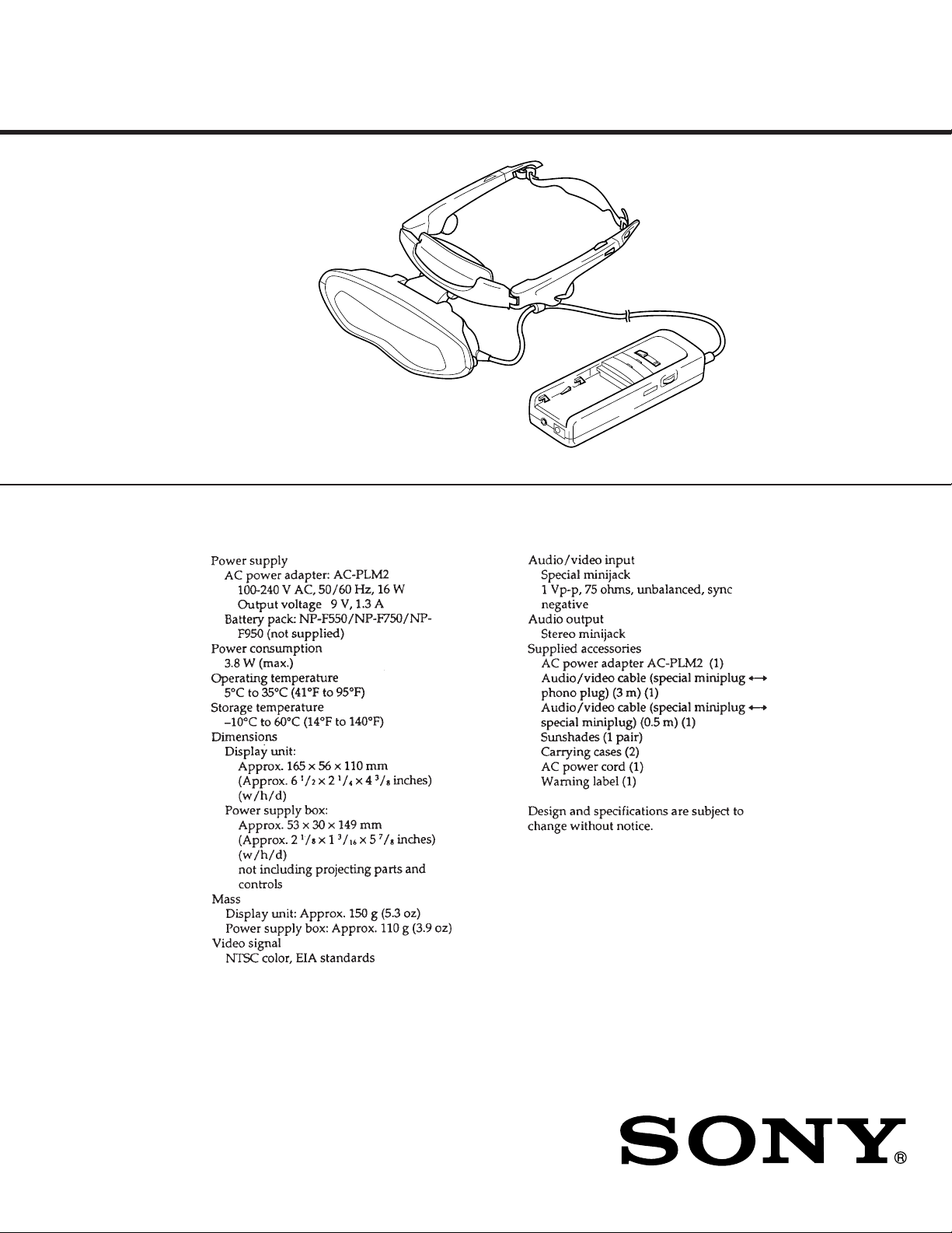
SPECIFICATIONS
US Model
Canadian Model
Singapore Model
MICROFILM
9-928-101-11
GLASSTRON

TABLE OF CONTENTS
1. GENERAL
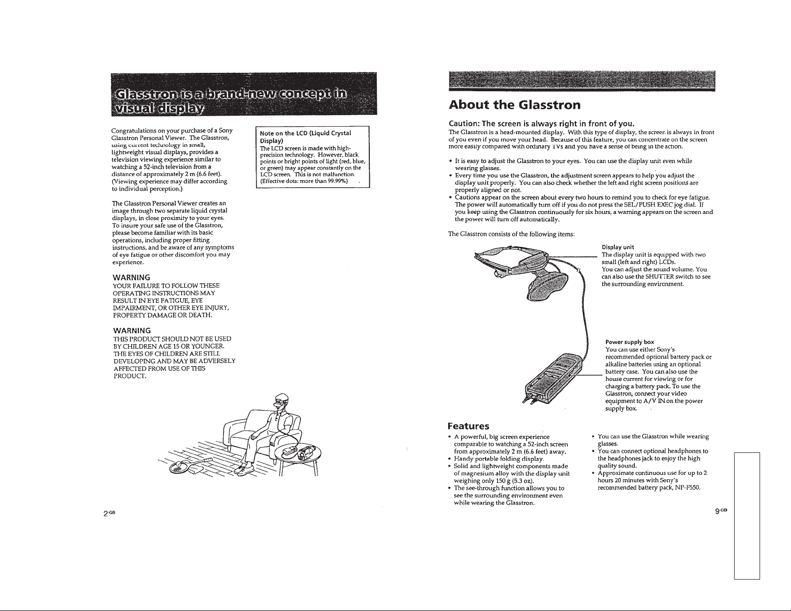
Glasstron is a brand-new concept in visual display ......... 3
About the Glasstron .......................................................... 3
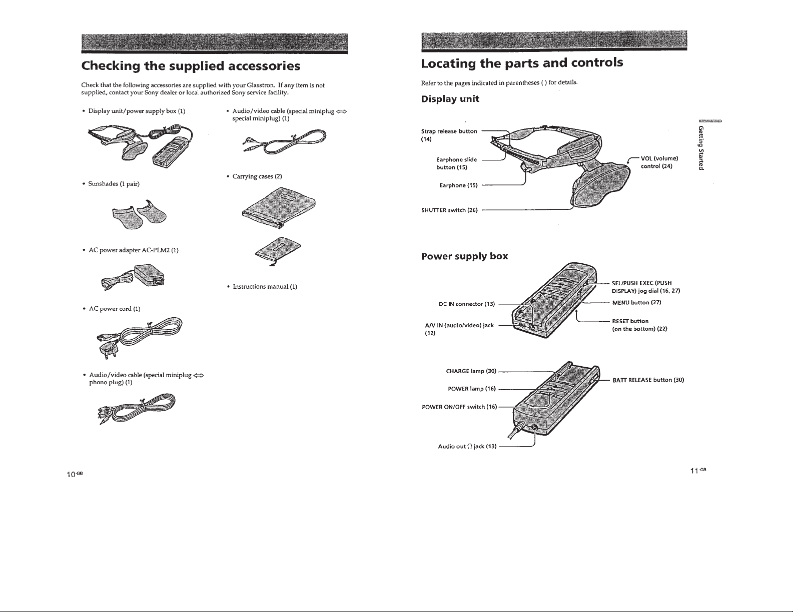
Checking the supplied accessories ................................... 4
Locating the parts and controls......................................... 4
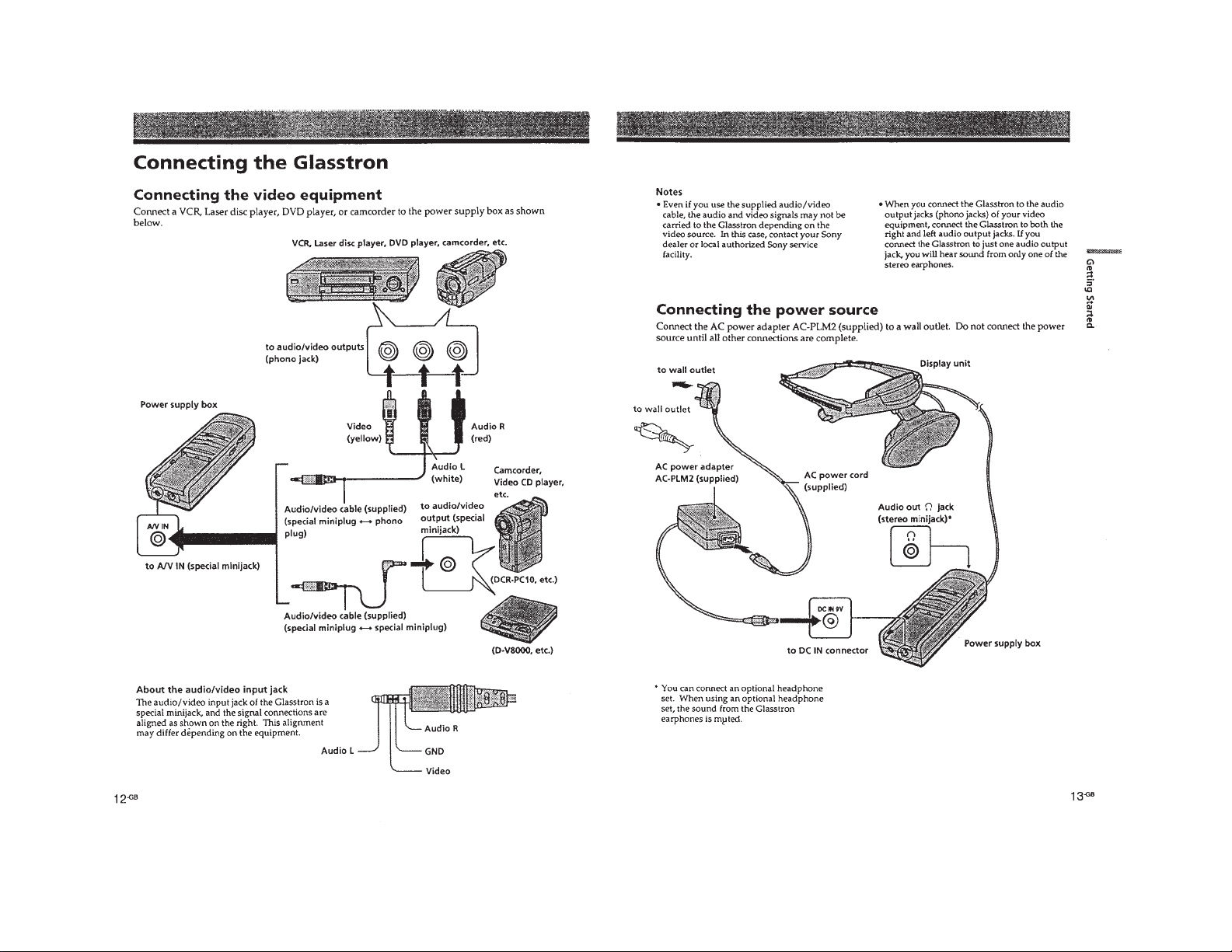
Connecting the Glasstron.................................................. 5
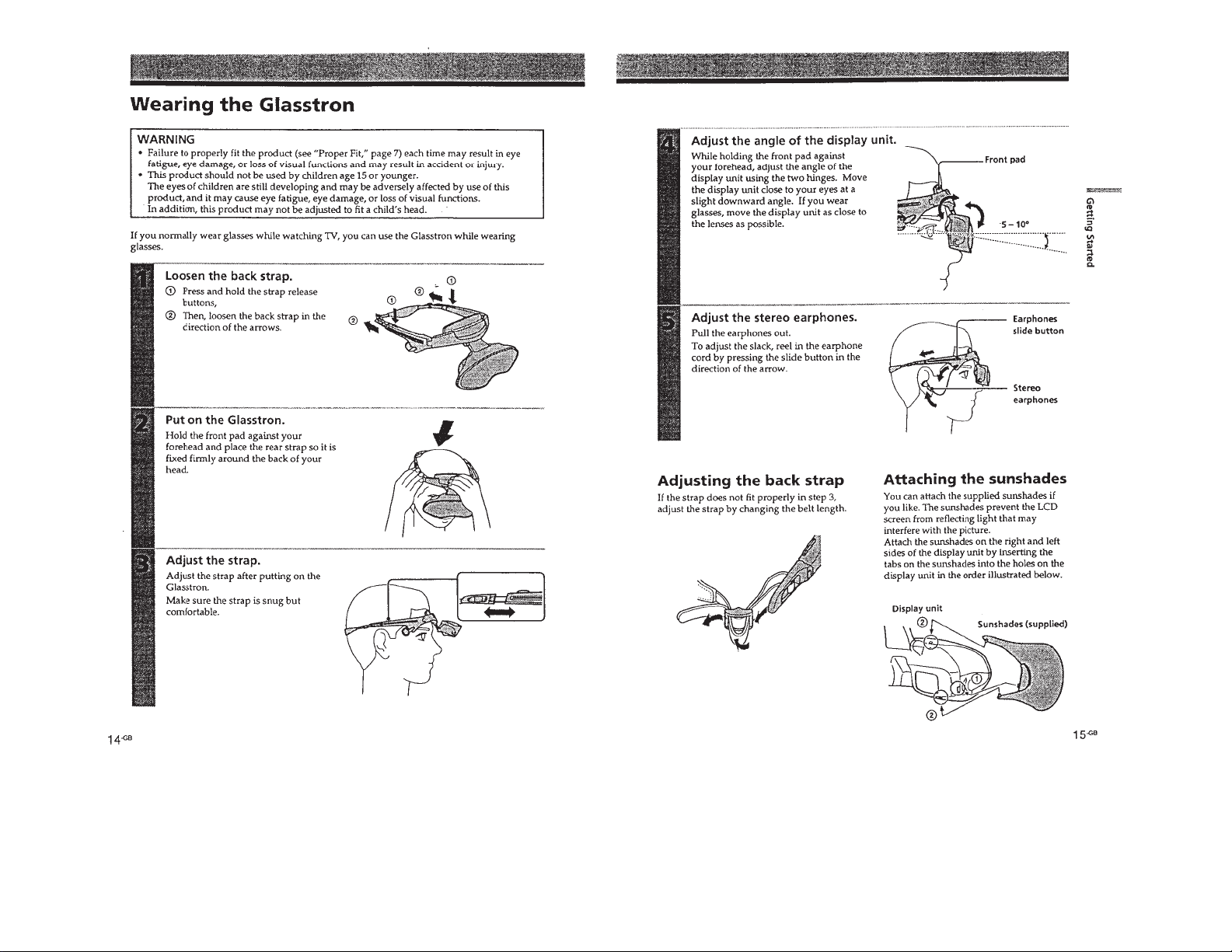
Wearing the Glasstron....................................................... 6
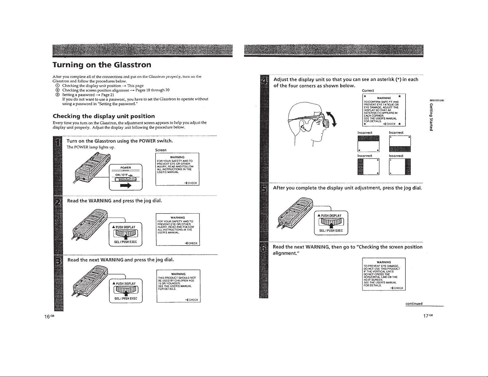
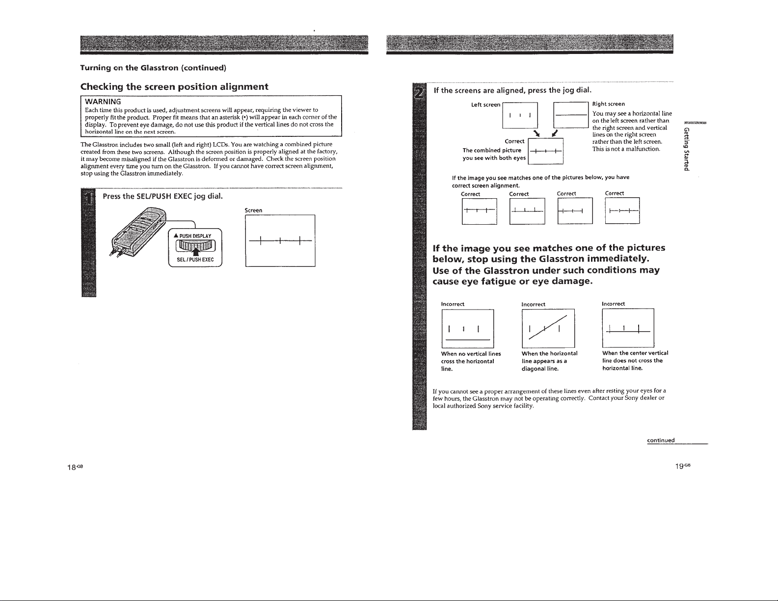
Turning on the Glasstron .................................................. 7
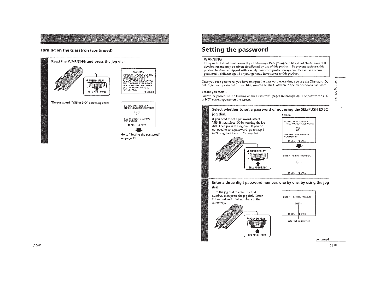
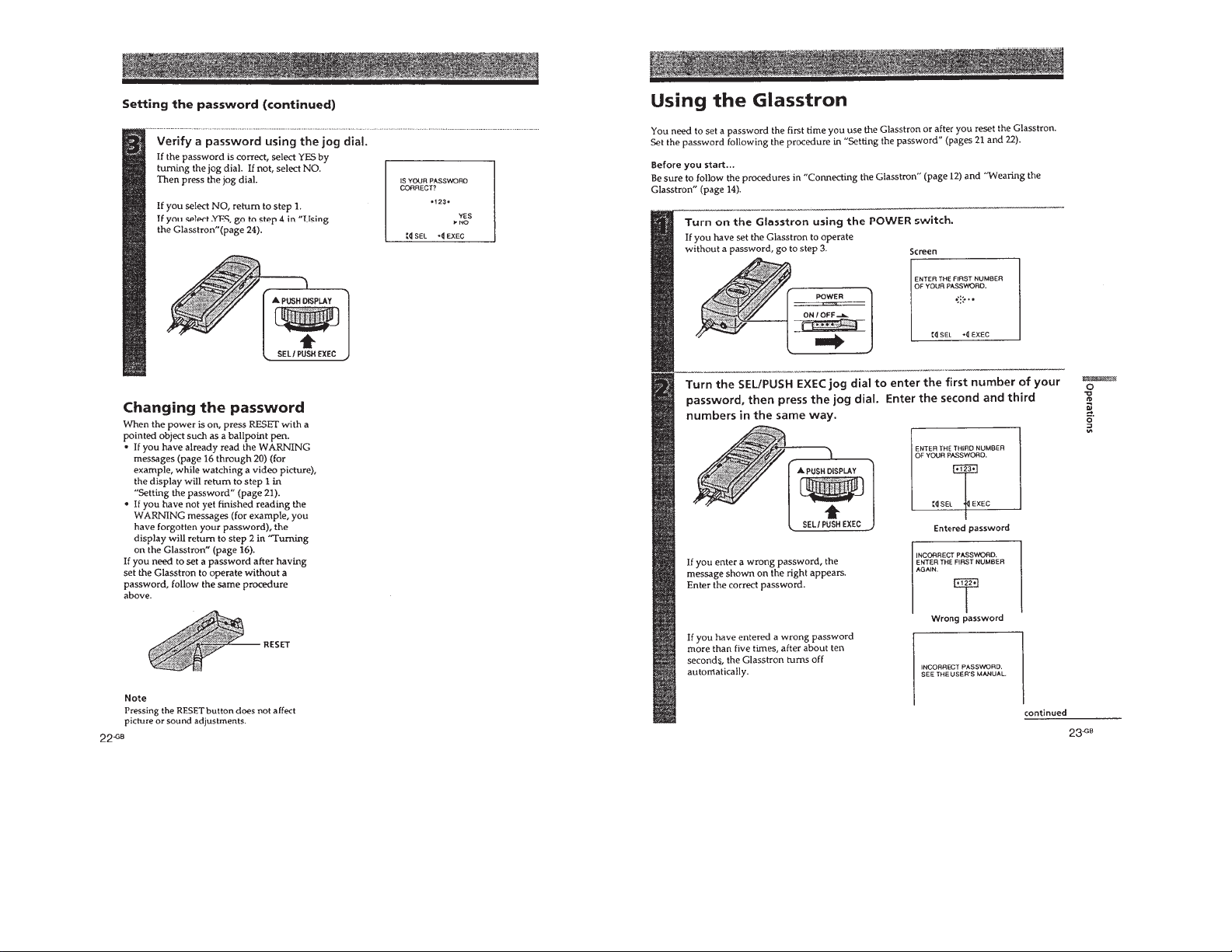
Setting the password ......................................................... 9
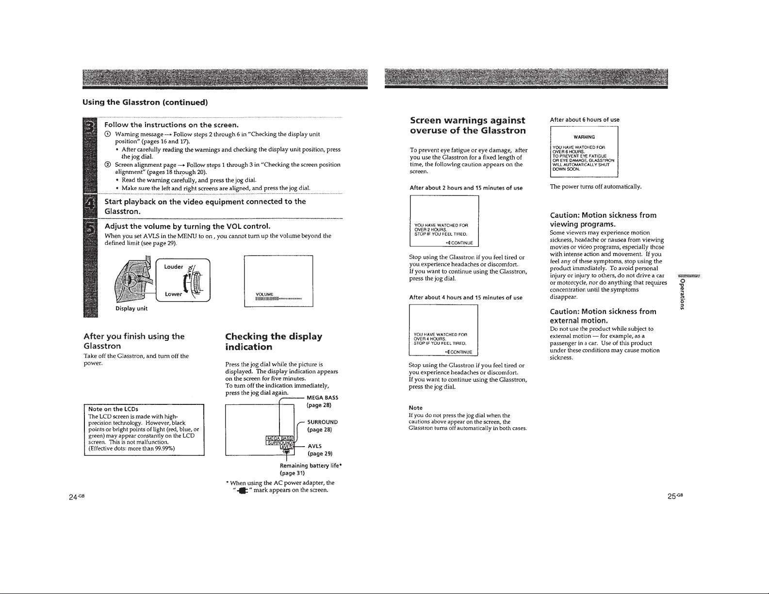
Using the Glasstron........................................................... 10
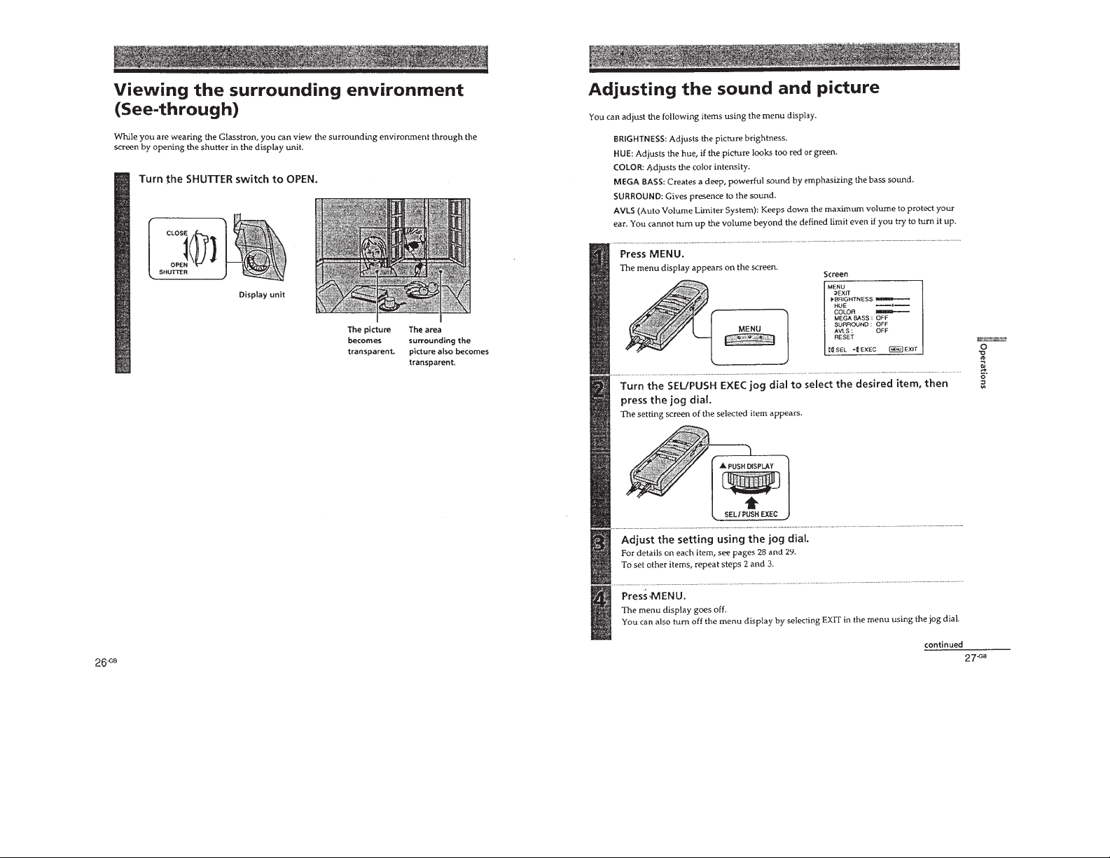
Viewing the surrounding environment
(See-through) .................................................................... 12
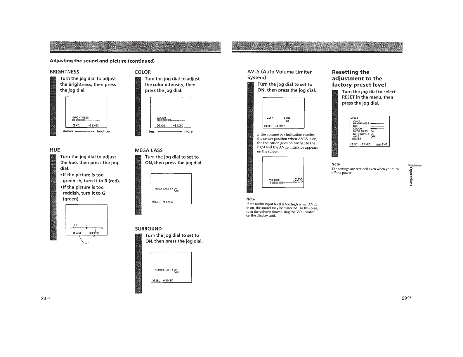
Adjusting the sound and picture ....................................... 12
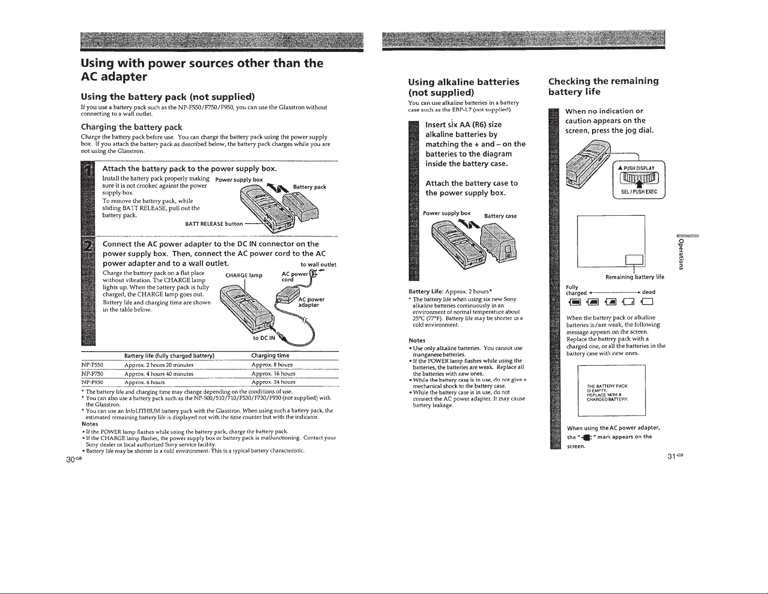
Using with power sources other than
the AC adapter ................................................................... 14
2. DISASSEMBLY ........................................................... 15
3. ELECTRICAL ADJUSTMENTS........................... 17
Power Supply Block ......................................................... 18
Video Block....................................................................... 26
LCD Block ........................................................................ 27
4. DIAGRAMS
4-1. IC Pin Function Description ............................................. 34
4-2. Block Diagram – MAIN Section –.................................. 41
4-3. Block Diagram – AUDIO/KEY CONTROL Section –... 43
4-4. Block Diagram – DISPLAY Section – ............................ 45
4-5. Block Diagram – POWER SUPPLY Section – ............... 47
4-6. Printed Wiring Boards
– YM-11 Board/SW-312 Board – ..................................... 50
4-7. Schematic Diagram – YM-11 Board (1/3) – .................... 53
4-8. Schematic Diagram
– YM-11 Board (2/3)/SW-312 Board – ............................ 57
4-9. Schematic Diagram – YM-11 Board (3/3) – .................... 61
4-10. Schematic Diagram – SA-52 Board – .............................. 66
4-11. Printed Wiring Board – SA-52 Board – .......................... 69
4-12. Printed Wiring Board – RG-46 Board – .......................... 71
4-13. Schematic Diagram – RG-46 Board – ............................. 73
Notes on chip component replacement
• Never reuse a disconnected chip component.
• Notice that the minus side of a tantalum capacitor may be damaged by heat.
Flexible Circuit Board Repairing
• Keep the temperature of the soldering iron around 270 ˚C during
repairing.
• Do not touch the soldering iron on the same conductor of the
circuit board (within 3 times).
• Be careful not to apply force on the conductor when soldering or
unsoldering.
5. EXPLODED VIEWS.................................................. 85
6. ELECTRICAL PARTS LIST ................................. 88
SAFETY-RELATED COMPONENT WARNING!!
COMPONENTS IDENTIFIED BY MARK ! OR DOTTED
LINE WITH MARK ! ON THE SCHEMATIC DIAGRAMS
AND IN THE PARTS LIST ARE CRITICAL TO SAFE
OPERATION. REPLACE THESE COMPONENTS WITH
SONY PARTS WHOSE PART NUMBERS APPEAR AS
SHOWN IN THIS MANU AL OR IN SUPPLEMENTS PUBLISHED BY SONY.
ATTENTION AU COMPOSANT AYANT RAPPORT
À LA SÉCURITÉ!
LES COMPOSANTS IDENTIFIÉS P AR UNE MARQUE !
SUR LES DIAGRAMMES SCHÉMATIQUES ET LA LISTE
DES PIÈCES SONT CRITIQUES POUR LA SÉCURITÉ
DE FONCTIONNEMENT. NE REMPLACER CES COMPOSANTS QUE PAR DES PIÈCES SONY DONT LES
NUMÉROS SONT DONNÉS DANS CE MANUEL OU
DANS LES SUPPLÉMENTS PUBLIÉS PAR SONY.
– 2 –
– 3 –
SECTION 1
GENERAL
This section is extracted from
instruction manual.
– 4 –
– 5 –
Singapore
US, CND
– 6 –
– 7 –
– 8 –
– 9 –
– 10 –
– 11 –
– 12 –
– 13 –
– 14 –
DISASSEMBLY
Note: Follow the disassembly procedure in the numerical order given.
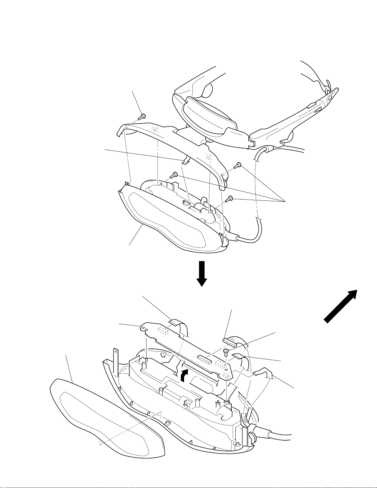
OPTICS OVERALL SECTION
1
screw
×
3.0)
(M1.4
2
FP30 flexible board
(CN405)
SECTION 2
RG-46 BOARD
6
1
front panel
3
optics overall section
RG-46 board
5
flexible board
(CN402)
4
2
connector
(CN401)
1
three screws
(M1.4
3
screw (M1.7)
5
flexible board (CN403)
×
3.0)
– 15 –
5
FP-29 flexible board
(CN406)
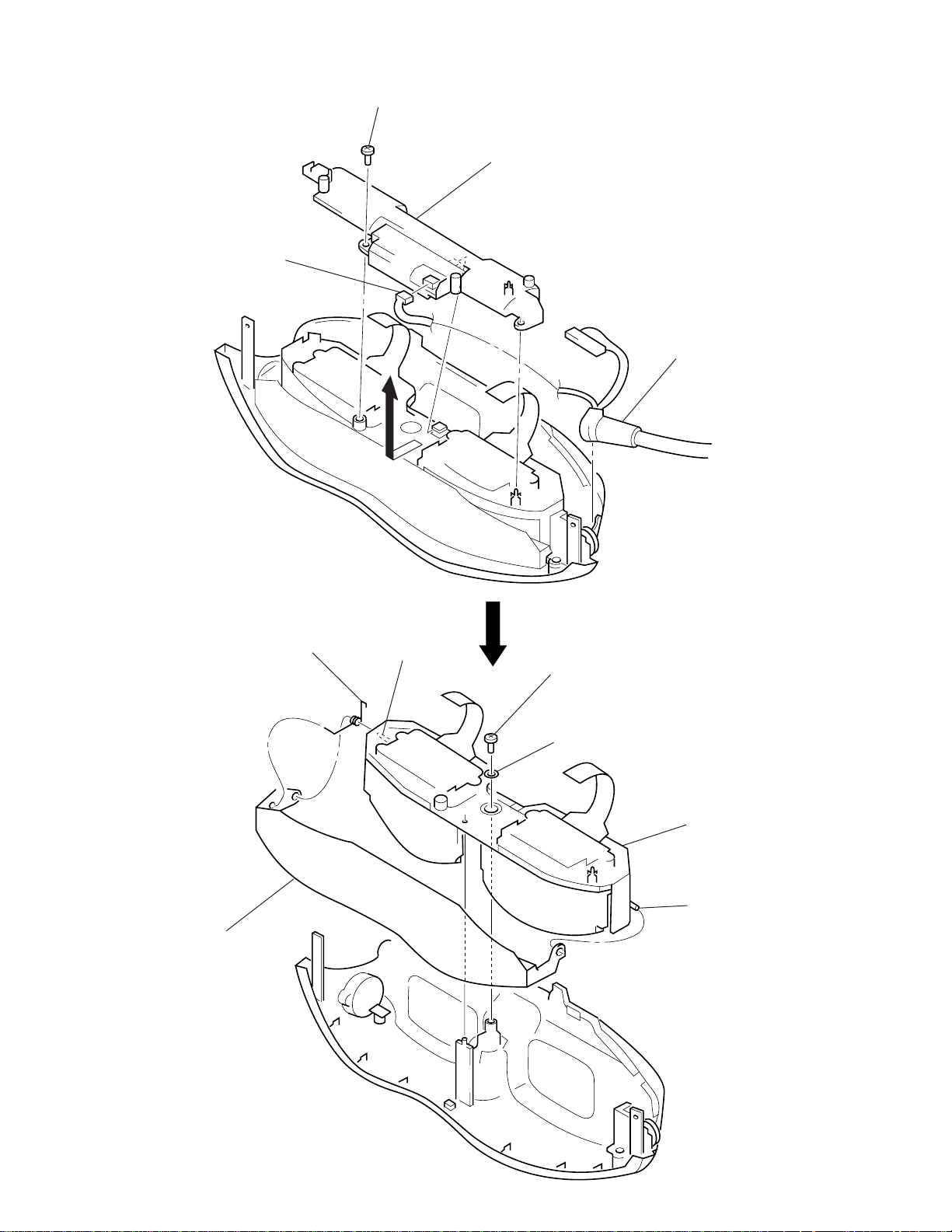
BACK LIGHT UNIT
d
y
1
connector
2
screw (M1.7)
3
back light unit
4
connection (MR) cor
OPTICS BLOCK ASS’Y
5
shutter
6
torsion spring
4
boss
1
screw
(M1.7
2
×
washer
4)
3
optics black ass’
4
boss
– 16 –
SECTION 3
White (100%)
approx.
0.3 V
approx.
0.7 V
approx.
0.3 V
• When color bar signals are entered
Red
Burst signal (flat)
Horizontal sync signal
• Chroma signal and color bar signal (Y signal) when burst
signal is turned off
No burst signal
Horizontal sync signal
approx.
0.7 V
approx.
0.3 V
White (100%)
ELECTRICAL ADJUSTMENTS
Precautions on adjustment:
1. Perform the adjustment in the given order.
2. Power supply voltage: DC 9.0 V
3. Equipment required
Electrical adjustment requires the following measuring equipment.
(1) Oscilloscope: 2 phenomena, band 30 MHz or more, with de-
lay mode (use 10 : 1 probe unless otherwise specified)
(2) Pattern generator
(3) Digital voltmeter
(4) Frequency counter
(5) Connector for adjustment
4. Measurement points for adjustment are located at CN102 on
the YM-11 board for VIDEO block, and at CN404 on the RG46 board for LCD block. The pin No. and signal name of CN102
and CN404 are listed below.
• YM-11 Board, CN102
Pin No. Signal Name
1 T.GND
2 FREE RUN ON
3 LANC SIG
4V IN
5 CHK BL+B
Pin No. Signal Name
6 HAFC
7 POWER SW
8Y
9 VCLVL
10 SC OUT
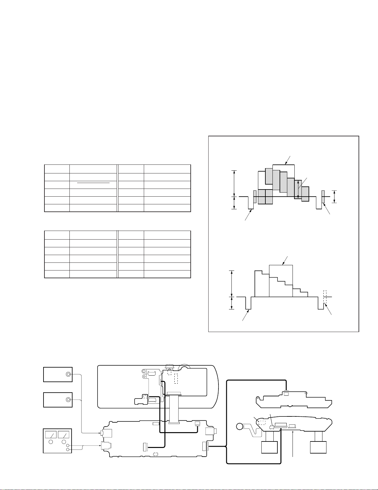
6. Setting up Input Signals
In adjusting this set, video signals obtained from the pattern
generator are used, and therefore these video output signals must
satisfy the specification. Connect the oscilloscope to the VIDEO
IN terminal, and confirm that the sync signal amplitude of video
signals is approximately 0.3 V, the amplitude of video part is
approximately 0.7 V, burst signal amplitude is approximately
0.3 V and flat, and the level ratio of burst signal to “red” signal
is 0.30 : 0.66.
Where “chroma signal, and color bar signal with burst signal
turned off” is specified in the text, enter chroma signal and color
bar signal of which burst signal is turned off to the VIDEO IN
terminal as video input signals for adjustment.
• RG-46 Board, CN404
Pin No. Signal Name
1 GND
2 EAC OFF
3 HP L
4 G OUT
5 HP R
Pin No. Signal Name
10 N.C
5. Setting Method of External Video Input Mode
Turn the PO WER switch on, and operate the SEL/PUSH EXEC
jog dial, so that the EXT. VIDEO IN mode becomes active.
(Refer to item 9 on page 22)
Preparation:
Connect all electrical blocks as shown below.
IF BOX Upper Cabinet
VIDEO
SG
AUDIO
SG
DC 9.0 V
suitable
SW-312
J101
J301
CN301
6 B OUT
7 HP RET
8 R OUT
9 PCO
S702
CN902
CN102
S703
S701
FFC
CN903
YM-11
SA-52
– 17 –
Fig. 3-1. Pattern generator's color bar signals
Back Light Unit
CN404
CN406
FP-29
CN401
Headphone L,R load 16
CN405
RG-46
LCDLCD
Ω ×
2
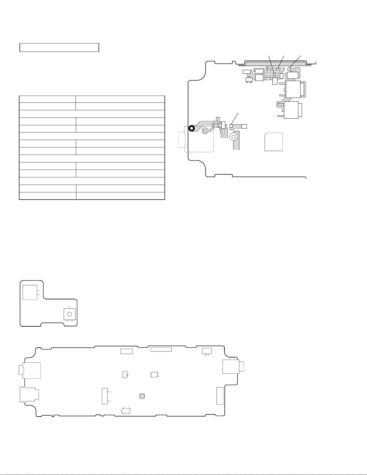
POWER SUPPLY BLOCK
[Power supply voltage check] (YM-11 board)
1. Turn the POWER s witch on, and confirm that the PO WER LED
(green) lights up.
2. Confirm that the voltage at each check land (CL) on the YM-11
board satisfies the specification value in Table below. As the
ground, use J101 pin 1 GND.
Input No signal input
Measuring equipment Digital voltmeter
V 5.0 V check
Measurement point CL305
Specification value 4.85 ± 0.1 V
D 5.0 V check
Measurement point CL307
Specification value 4.95 ± 0.1 V
13.5 V check
Measurement point CL306
Specification value 13.50 ± 0.2 V
AU 2.0 V check
Measurement point CL308
Specification value 1.85 ± 0.1 V
3. Press the battery detection switch (S705) on the SW-312 board.
(Switch with fixed pawl at the lower right of battery)
Or, short CN903 pin 1 and pin 2 on the YM-11 board.
(CHARGE mode becomes active.) At this time, confirm that
the CHARGE LED (orange) lights up.
4. Under this condition, confirm that the voltage of CN301 pin 1
on the YM-11 board is 8.4 ± 0.1 V.
5. After checking, remove a jumper wire used for short in step 3.
[YM-11 board] (Side B)
GND
J101
D103
D309
CL308
CL307 CL306
Q318
Q317
IC301
CL305
Check Parts:
[SW-312 board] (Component side)
CN702
S705
[YM-11 board] (Side A)
CN903
12
CN301
5
1
– 18 –
[Preparation for Preset Data Writing, Battery Down
Adjustment, and Charge Threshold Level Adjustment]
1 “Preset Data Writing”, “Battery Down Adjustment”, “Charge
Threshold Level Adjustment” and all adjustments of “Video
Block” must be performed, if IC901 (EEPROM) on the YM-11
was replaced.
2 “Battery Down Adjustment” and “Charge Threshold Level Ad-
justment” must be performed, if IC902 (5 V REG.) or IC903
(microprocessor) on the YM-11 was replaced.
3 All adjustments of “Video Block” must be performed, if IC101
(OSD), IC103 (Y/C separation), IC201 (Y/R-Y/B-Y decoder)
on the YM-11 board, or IC401 (LCD driver) on the RG-46 board,
or LCD (optical block) was replaced.
1. Service Jigs
(1) Adjusting remote commander (RM-95-modified)
Note 1: J-6082-053-B
(2) Extension cable (for remote commander plug converter)
J-6082-291-A
Note 1: T he page will not be changed over, unless the microprocessor in
the adjusting remote commander is a new one (UPD7503-G-C56-
12). In such a case, replace with new microprocessor (8-759-148-
35).
2. Adjusting Remote Commander
For the adjustment, the adjustment data saved in the nonvolatile
memory (EEPROM) must be rewritten, and for this purpose the
adjusting remote commander is used.
The adjusting remote commander makes two-way communication with the product using a remote control signal line (LANC).
The adjusting remote commander transmits pages, addresses,
and data up/down commands to the product. The product transmits pages, addresses, and data to the adjusting remote commander.
3. How to Use Adjusting Remote Commander
(1) Connect the adjusting remote commander to the CN902 on YM-
11 board via extension cable (J-6082-291A).
At this time, set the switch of extension cable to OFF
(
(OPEN) position.
Turn ON the power on the set.
(2) Set the HOLD switch on the adjusting remote commander to
the HOLD (SERVICE) position.
If connection is normal, the LCD display on the adjusting remote commander will be as shown in Fig.3-2.
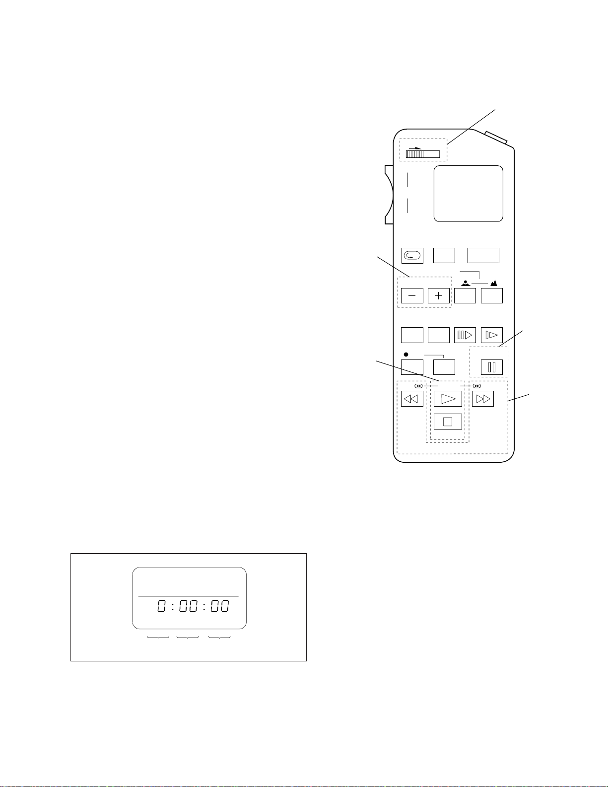
Adjusting Remote Commander RM-95 (J-6082-053-B)
NORMAL/SERVICE
mode selection
HOLD
WIDE
ZOOM
TELE
REC
Page change
Data change
REVIEW
COUNTER
RESET DISPLAY FRAME SLOW
REW
)
FOCUS
AUTO/MAN
EDIT SEARCH
REC
PB
STOP
Fig. 3-3
START/
STOP
POWER
PAUSE
FF
RM-95
Data writing
Address
change
Page Data Address
Fig. 3-2
– 19 –

(3) Operate the adjusting remote commander as follows:
• Page change
Press the EDIT SEARCH + button to increase the page.
Press the EDIT SEARCH – button to decrease the page.
There are 16 pages from 0 to F.
Hexadecimal numbers
LCD display
Decimal conversion
0123456789ABCDEF
23456789 A b c d E F
10
2 3 4 5 6 7 8 9 10 11 12 13 14 15
10
• Address change
Press the FF ()) button to increase the address.
Press the REW (0) button to decrease the address.
There are 256 addresses from 00 to FF.
• Data change (data setting)
Press the PLAY (() button to increase the data.
Press the STOP (p) button to decrease the data.
There are 256 data from 00 to FF.
• Adjustment data writing
The P A USE button must be pressed to write adjustment data
(D page) to the nonvolatile memory (EEPROM). (Unless
the PAUSE is pressed, new data are not saved in the nonvolatile memory.)
(4) Select page: 1, address: 00, and set 01 data. Thus, the data
input to page: D, address: 00 – 1A is enabled.
(5) After the adjustment finished, select page: 1, address: 00, and
set 00 data. Thus, the data change on page D is disabled.
(6) After all adjustments finished, turn OFF the main power sup-
ply (9.0 V) once.
4. Precaution on Use of Adjusting Remote Commander
Misoperation of the adjusting remote commander could erase
correct data. To prevent this, it is recommended to make a note
of data from address 00 to 4B on page D before adjust-ment,
and also to make a note of new adjustment data each time the
adjustment of one item is finished.
– 20 –
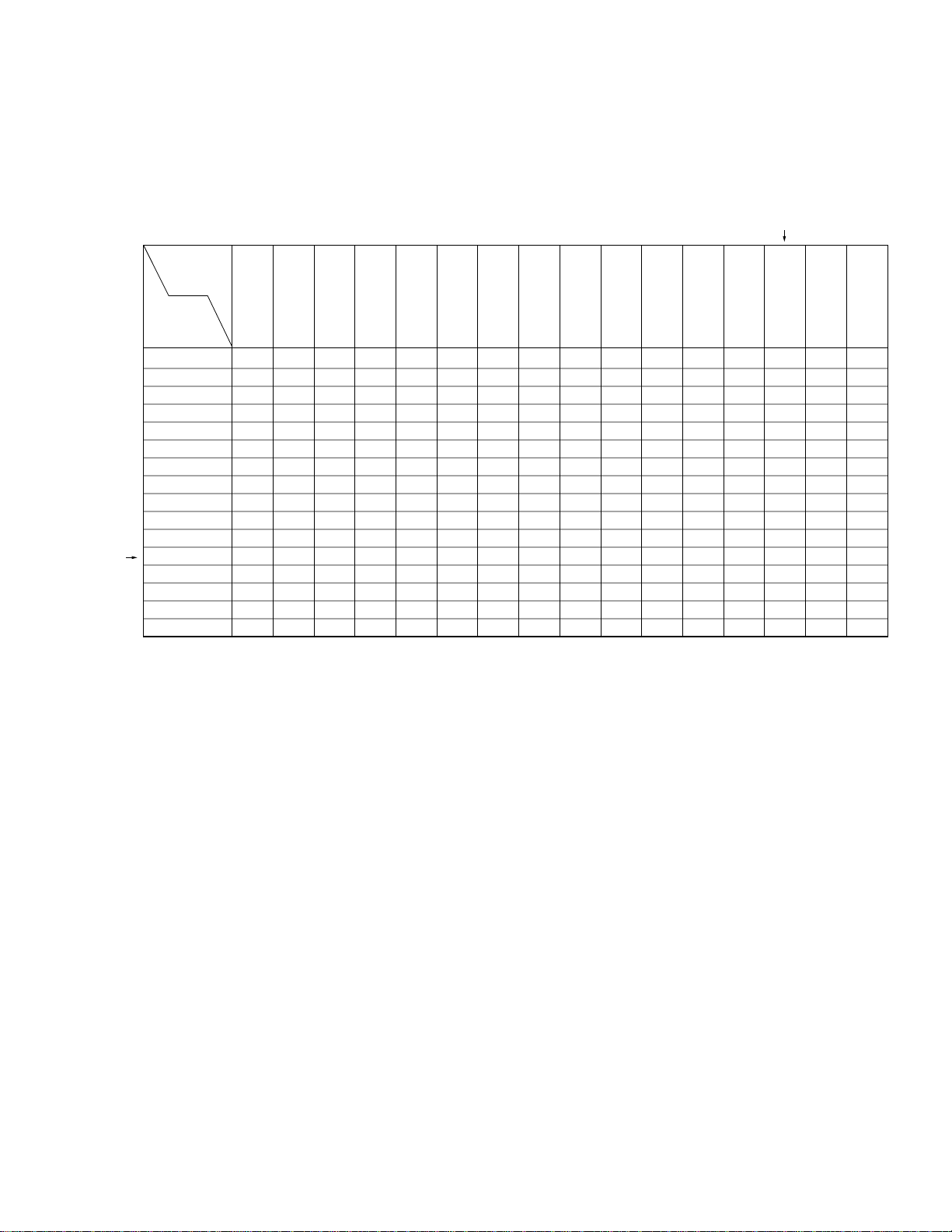
5. Data Processing
Certain adjustment items require the microprocessor data to be read out or the displayed data (hexadecimal numbers) on jigs or adjusting
remote commander to be calculated to get adjustment data. In such a case, convert hexadecimal numbers into decimal numbers once, then
make calculation, and convert its result into hexadecimal number as adjustment data. Table 1 shows hexadecimal – decimal number
conversion.
Hexadecimal – Decimal number conversion.
Lower digit
of hex.
0123456789
Higher digit
of hex.
123456789
00
1
1
2
3
4
5
6
7
8
9
A (A)
B (b)
C (c)
D (d)
E (E)
F (F)
16 17 18 19 20 21 22 23 24 25
32 33 34 35 36 37 38 39 40 41
48 49 50 51 52 53 54 55 56 57
64 65 66 67 68 69 70 71 72 73
80 81 82 83 84 85 86 87 88 89
96 97 98 99 100 101 102 103 104 105
112 113 114 115 116 117 118 119 120 121
128 129 130 131 132 133 134 135 136 137
144 145 146 147 148 149 150 151 152 153
160 161 162 163 164 165 166 167 168 169
176 177 178 179 180 181 182 183 184 185
192 193 194 195 196 197 198 199 200 201
208 209 210 211 212 213 214 215 216 217
224 225 226 227 228 229 230 231 232 233
240 241 242 243 244 245 246 247 248 249
T able 1.
2
A
(A) B(b) C(c) D(d) E(E) F(F)
10
26
42
58
74
90
106
122
138
154
170
186
202
218
234
250
11
27
43
59
75
91
107
123
139
155
171
187
203
219
235
251
12
13 14 15
28
29 30 31
44
45 46 47
60
61 62 63
76
77 78 79
92
93 94 95
108
109 110 111
124
125 126 127
140
141 142 143
156
157 158 159
172
173 174 175
188
189 190 191
204
205 206 207
220
221 222 223
236
237 238 239
252
253 254 255
Note: Data in ( ) are displayed on jig or adjusting remote commander.
Example:If display on jig or adjusting remote commander is BD (bd)
As higher digit of hex. number is B (b) and lower digit is D (d), the intersection “189” of 1 and 2 in Table 1 is the target decimal number.
– 21 –
 Loading...