

Sony PlayStation 2 SCPH-3000 R series, PlayStation 2 SCPH-3003 R, PlayStation 2 SCPH-3002 R, PlayStation 2 SCPH-3004 R Service Manual

Quality Asurance Department
Published in Japan 2.2002. 9-927-093-61
SCPH-30000 R series
SERVICE MANUAL
for GH015(31/41) MOUNT
6th edition
( F-type model )
SCPH-30002 R
SCPH-30003 R
SCPH-30004 R

Reproduction Prohibited
— GH015(31/41)-2 —
SCPH-30000 R series
F-type model
NOTICE
Copyright by Sony Computer Entertainment Inc. All rights reserved. No reproduced and transferred required except
permission by Sony Computer Entertainment Inc. No commercial use and rental required.
REVISIONS.
Design and Specification will be subject to changed without notice. The latest versions of service manual, Technical
memo, Technical information should be used together.
SAFETY-RELATED COMPONENT WARNING !!
COMPONENTS IDENTIFIED BY MARK OR DOTTED LINE WITH MARK ON THE SCHEMATIC DIAGRAMS
AND IN THE PARTS LIST ARE CRITICAL TO SAFE OPERATION. REPLACE THESE COMPONENTS WITH SONY
PARTS WHOSE PART NUMBERS APPEAR AS SHOWN IN THIS MANUAL OR IN SUPPLEMENTS PUBLISHED
BY SONY.
ATTENTION AU COMPOSANT AYANT RAPPORT À LA SÉCURITÉ !
LES COMPOSANTS IDENTIFIÉS PAR UNE MARQUE SUR LES DIAGRAMMES SCHÉMATIQUES ET LA LISTE
DES PIÈCES SONT CRITIQUES POUR LA SÈCURITÈ DE FONCTIONNEMENT. NE REMPLACER CES COMPOSANTS QUE PAR DES PIÈCES SONY DONT LES NUMÉROS SONT DONNÉS DANS CE MANUEL OU DANS
LES SUPPLÉMENTS UBLIÉS PAR SONY.
CAUTION
Replace the battery with a Sony CR2032 battery. Use of any other type of battery may present the risk of fire or
explosion. The battery may explode if mistreated. Do not recharge, disassemble, or dispose of in fire.
CAUTION
The use of optical instruments with this product will increase eye Hazard. As the laser beam used in this CD/DVD
player is harmful To eyes, do not attempt to disassemble the cabinet. Refer servicing to qualified personnel only.
WARNING !!
WHEN SERVICING, DO NOT APPROACH THE LASER EXIT WITH THE EYE TOO CLOSELY. IN CASE IT IS
NECESSARY TO CONFIRM LASER BEAM EMISSION, BE SURE TO OBSERVE FROM A DISTANCE OF MORE
THAN 25cm FROM THE SURFACE OF THE OBJECTIVE LENS ON THE OPTICAL PICK-UP BLOCK.
CAUTION
Use of controls or adjustments or performance of procedures other than those specified herein may result in
hazardous radiation exposure.
CAUTION for electric shock
When power is ON, Don’t touch to Power supply block, AC-inlet, Power switch and so on, not to get an electric shock
at repair.
CAUTION for burning
When current is supplied, Some of part surface temperature like EE, GS, Regulater-IC, power supply, Optical device
and so on. These part surface is become high temperature condition. When it repair, Don’t touch them at a time during
it surface is high temperature condition to take prevent against burning. Do repair after it is cooled down enough.
CAUTION
Danger of explosion if battery is incorrectly replaced. Replace only with the same or equivalent type recommended by
the manufacturer. Discard used batteries according to the manufacturer’s instructions.
ADVARSEL!
Lithiumbatteri - Eksplosionsfare ved fejlagtig håndtering. Udskiftning må kun ske med batteri af samme fabrikat og
type. Levér det brugte batteri tilbage til leverandøren.
ADVARSEL
Eksplosjonsfare ved feilaktig skifte av batteri. Benytt samme batteritype eller en tilsvarende type anbefalt av
apparatfabrikanten. Brukte batterier kasseres i henhold til fabrikantens instruksjoner.
VARNING
Explosionsfara vid felaktigt batteribyte. Använt samma batterityp eller en ekvivalent typ som rekommenderas av
apparattillverkaren. Kassera använt batteri enligt fabrikantens instruktion.
VAROITUS
Paristo voi räjähtää, jos se on virheellisesti asennettu. Vaihda paristo ainoastaan valmistajan suosittelemaan tyyppiin.
Hävitä käytetty paristo valmistajan ohjeiden mukaisesti.
SAFETY CHECK-OUT
After correcting the original service problem, perform the following safety checks before releasing the set to the
customer:
1. Check the area of your repair for unsoldered or cold-soldered connections. Check the entire board surface for
solder splashes and bridges.
2. Check the inter board wiring to ensure that no wires are “pinched” or contact high-wattage resistors.
3. Look for unauthorized replacement parts, particularly transistors, that were installed during a previous repair. Point
them out to the customer and recommend their replacement.
4. Look for parts which, though functioning, show obvious signs of deterioration. Point them out of the customer and
recommend their replacement.
5. Check the line cord for cracks and abrasion. Recommend the replacement of any such line cord to the customer.
6. Check the b+ voltage to see it is at the values specified.
7. Check the antenna terminals, metal trim, “metalized” knobs, screws, and all other exposed metal parts for ac
leakage. Check leakage as described below.
LEAKAGE
The AC leakage from any exposed metal part to earth ground and from all exposed metal parts to any exposed metal
part having a Return to chassis, must not exceed 0.5 mA (500 micro-ampers). Leakage current can be measured by
any one of three methods.
1. A commercial leakage tester, such as the SIMPSON 229 or RCA WT-540A. Follow the manufacturers’ instructions
to use these instruments.
2. A battery-operated AC milli-ammeter. The Data Precision 245 digital multi-meter is suitable for this job.
3. Measuring the voltage drop across a resistor by means of a VOM or battery-operated ac voltmeter. The “limit”
indication is 0.75V, so analog meters must have an accurate low-voltage scale. The SIMPSON 250 and SANWA
SH-63TRD are examples of a passive VOM that is suitable. Nearly all battery operated digital multi-meters that
have a 2V AC range are suitable.
Fig A. Using AC voltmeter to check AC leakage
To Exposed Metal
Parts on Set
1.5 k
Ω
0.15 µF
AC
voltmeter
(0.75V)
Earth Ground
This manual compiled by second edition of SCPH-30000 R series D type and F type models design data.
NOTIFICATION for environmental assessment
This model is CR2032 lithium battery onboard inside on the GB MOUNT or GH MOUNT as Timer backup power.
CR2032 life may be about 5 to 8 years, so you have very few need for changing to new one. But if you have necessary
to replaced to new one or disassemble for scrapping, you have to keep your country law, regulation, standard, etc. of
environmental assessment and safety.

Reproduction Prohibited
— GH015(31/41)-3 —
SCPH-30000 R series
F-type model
TABLE OF CONTENTS
SPECIFICATIONS
NOTICE AND REVISION
EXPLODED VIEWS
Overall and Main Block
....................................................
.................................
GH015(31/41)-4
GH015(31/41)-2
GH015(31/41)-5
MD Block
.........................................................................
GH015(31/41)-6
GH Mount Block and Shield (A) Assy Block
.....................
Switch Assy Block
...........................................................
....................................................
.............................................................
GH015(31/41)-7
Power Switch, Fan and Rear Panel Assy Block
.....
...................
.....
GH015(31/41)-8
BLOCK DIAGRAM
...........................................................
GH015(31/41)-9
PRINTED WIRING BOARDS AND SCHEMATIC DIAGRAMS
Note for Printed Wiring Boards and Schematic Diagrams
GH015(31/41)-13
GH015(31/41)-12
GH015(31/41)-11
GH015(31/41)-10
GH015(31/41) Mount Schematic Diagrams
GH015(31/41) Mount Wiring Boards
GH015(31/41)-14
GH015(31/41)-22
Electrical Parts List
GH015(31/41)-24
Switch Mount
GH015(31/41)-29
..................................................................
........................
.................................
...........................................................
SCPH-30000 R F-type model with GH015(31/41) MOUNT
SUPPLIED ACCESSORIES AND PACKING BLOCK
INSTRUCTION MANUAL BLOCK

Reproduction Prohibited
— GH015(31/41)-4 —
SCPH-30000 R series
F-type model
SPECIFICATIONS
General
Power requirements
220 -240 V AC, 50/60 Hz
Power consumption
50 W
Dimensions
301 x 78 x 182 mm (w/h/d)
Mass
2.4 kg
Inputs/Outputs on the front
Controller ports (2)
Memory card slots (2)
USB ports (2)
S400 (i-Link) port (1)
Inputs/Outputs on the rear
HDD bay slot (1)
Outputs on the rear
AV Multi out port (1)
RGB, Ycbcr, Y/C, Composite-video,
Audio-L/R, XGA
Digital out port (1)
Optical audio
Supplied accessories
AC power cord (1)
A/V connecting cable (1)
Dualshock2 Analog controller (1)
Euro-AV Connector (1)
for SCPH-30003 R/-30004 R
Reproduction Prohibited
— GH015(31/41)-5 —
SCPH-30000 R series
F-type model
MASTER CARTON, 3 SETS
MASTER CARTON, 3 SETS
MANUAL BLOCK ASSY, INSTRUCTION
MANUAL BLOCK ASSY, INSTRUCTION
TAPE, BERODDED PREVENTION
TAPE, BERODDED PREVENTION
PAD, TOGETHER PACKING
INDIVIDUAL CARTON
INDIVIDUAL CARTON
SHEET, PROTECTION
SHEET, PROTECTION
AV
SUPPLIED ACCESSORIES AND PACKING BLOCK
NOTE :
•
•
•
Due to standardization, replacements in
the parts list may be different from the
parts specified in the diagrams or the
components used on the set.
-XX and -X mean standardized parts, so
they may have some difference from the
original one.
RESISTORS
METAL : Metal-film resistor.
F : nonflammable
Unit is .
•
•
•
SEMICONDUCTORS
In each case, u : µ, for example :
uA . .
uPB. .
CAPACITORS
uF : µF
COILS
uH : µH
: µA . .
: µPB. .
uPA . . : µPA . .
uPC . . : µPC . . uPD . . : µPD . .
The components identified by
mark ! or dotted line with mark.
!
are critical for safety.
Replace only with part number
specified.
Ref. Part No. Description
CONV 1-785-004-12 CONNECTOR, CONVERSION
CONNECTOR, CONVERSIONCONV 1-573-291-12
AC 1-751-115-21 CORD, POWER
CORD, POWER
CORD, POWER
CORD, POWER
ACAC1-751-115-31
1-751-115-43
AC 1-790-023-21
CU 3-064-714-01 CUSHION
SH 3-060-494-01
CA 3-071-634-12
PAD 3-065-172-01
MC 3-071-635-43
TA 3-987-483-11
IMB A-6785-377-A
SCPH-30002 R F-type model SCPH-30003 R F-type model SCPH-30004 R F-type model
AV
AV
AV
AV
AV
AV 1-792-028-11
AV CABLE (Integrated audio/video)
AV CABLE (Integrated audio/video)
AV CABLE (Integrated audio/video)
AV CABLE (Integrated audio/video)
AV CABLE (Integrated audio/video)
AV CABLE (Integrated audio/video)
1-792-028-22
1-792-028-42
1-792-028-32
1-792-028-51
1-792-028-61
AV
AV
AV
AV
AV
1-792-028-11
AV CABLE (Integrated audio/video)
AV CABLE (Integrated audio/video)
AV CABLE (Integrated audio/video)
AV CABLE (Integrated audio/video)
AV CABLE (Integrated audio/video)
AV CABLE (Integrated audio/video)
1-792-028-22
1-792-028-32
1-792-028-42
1-792-028-51
1-792-028-61
AV
AV
AV
AV
AV
AV
1-792-028-11 AV CABLE (Integrated audio/video)
AV CABLE (Integrated audio/video)
AV CABLE (Integrated audio/video)
AV CABLE (Integrated audio/video)
AV CABLE (Integrated audio/video)
AV CABLE (Integrated audio/video)
1-792-028-22
1-792-028-42
1-792-028-32
1-792-028-51
1-792-028-61
SUPPLIED ACCESSORIES and PACKING GROUP PLACE CODE #23
***********************************************************************
************************* ************************* *************************
Ref. Part No. Description
AC 1-555-074-51 CORD, POWER
CU 3-064-714-01 CUSHION
SH 3-060-494-01
CA 3-071-639-02
MC 3-071-635-53
TA 3-987-483-11
IMB A-6785-379-A
Ref. Part No. Description
CONV 1-785-004-12 CONNECTOR, CONVERSION
CONNECTOR, CONVERSIONCONV 1-573-291-12
AC 1-575-131-82 CORD, POWER
AC 1-823-152-11 CORD, POWER
CU 3-064-714-01 CUSHION
SH 3-060-494-01 SHEET, PROTECTION
CA 3-071-634-03 INDIVIDUAL CARTON
PAD 3-065-172-01 PAD, TOGETHER PACKING
MC 3-071-635-33 MASTER CARTON, 3 SETS
TA 3-987-483-11 TAPE, BERODDED PREVENTION
IMB
A-6785-382-A MANUAL BLOCK ASSY, INSTRUCTION
ANALOG CONTROLLER (DUALSHOCK 2)
ANALOG CONTROLLER (DUALSHOCK 2)
ANALOG CONTROLLER (DUALSHOCK 2)
1-823-069-51
1-823-069-61
1-823-552-12CONT
CONT
CONT
ANALOG CONTROLLER (DUALSHOCK 2)
ANALOG CONTROLLER (DUALSHOCK 2)
ANALOG CONTROLLER (DUALSHOCK 2)
1-823-069-51
1-823-069-61
1-823-552-12CONT
CONT
CONT
ANALOG CONTROLLER (DUALSHOCK 2)
ANALOG CONTROLLER (DUALSHOCK 2)
ANALOG CONTROLLER (DUALSHOCK 2)
1-823-069-51
1-823-069-61
1-823-552-12CONT
CONT
CONT

Reproduction Prohibited
— GH015(31/41)-6 —
SCPH-30000 R series
F-type model
INSTRUCTION MANUAL BLOCK
NOTE :
•
•
•
Due to standardization, replacements in
the parts list may be different from the
parts specified in the diagrams or the
components used on the set.
-XX and -X mean standardized parts, so
they may have some difference from the
original one.
RESISTORS
METAL : Metal-film resistor.
F : nonflammable
Unit is .
The components identified by
mark
!
or dotted line with mark.
!
are critical for safety.
Replace only with part number
specified.
INSTRUCTION MANUAL BLOCK ASSY
PLACE CODE #23
*******************************************************
Ref. Part No. Description
BOR 3-066-159-02 CARD (B), OWNER REGISTRATION
DISK 3-073-543-01 DISK, DEMONSTRATION
IM 3-071-581-33 MANUAL, INSTRUCTION
SE 3-987-375-02 SEAL, SEAL
Ref. Part No. Description
AOR 3-066-158-02 CARD (A), OWNER REGISTRATION
DISK 3-073-543-01 DISK, DEMONSTRATION
IM 3-071-581-22 MANUAL, INSTRUCTION
SE 3-987-375-02 SEAL, SEAL
Ref. Part No. Description
COR 3-066-160-04 CARD (C), OWNER REGISTRATION
DISK 3-073-543-01 DISK, DEMONSTRATION
IM 3-071-581-43 MANUAL, INSTRUCTION
IM 3-071-581-53 MANUAL, INSTRUCTION
SE 3-987-375-02 SEAL, SEAL
•
•
•
SEMICONDUCTORS
In each case, u : µ, for example :
uA . .
uPB. .
CAPACITORS
uF : µF
COILS
uH : µH
: µA . .
: µPB. .
uPA . . : µPA . .
uPC . . : µPC . . uPD . . : µPD . .
SCPH-30002 R F-type model
*************************
SCPH-30003 R F-type model
*************************
SCPH-30004 R F-type model
*************************
Reproduction Prohibited
SCPH-30000 R series
F-type model
— GH015(31/41)-7 —
The components identified by
mark ! or dotted line with mark.
! are critical for safety.
Replace only with part number
specified.
CAUTION :
Use of controls or adjustments or performance
of procedures other than those specified herein
may result in hazardous radiation exposure.
CAUTION
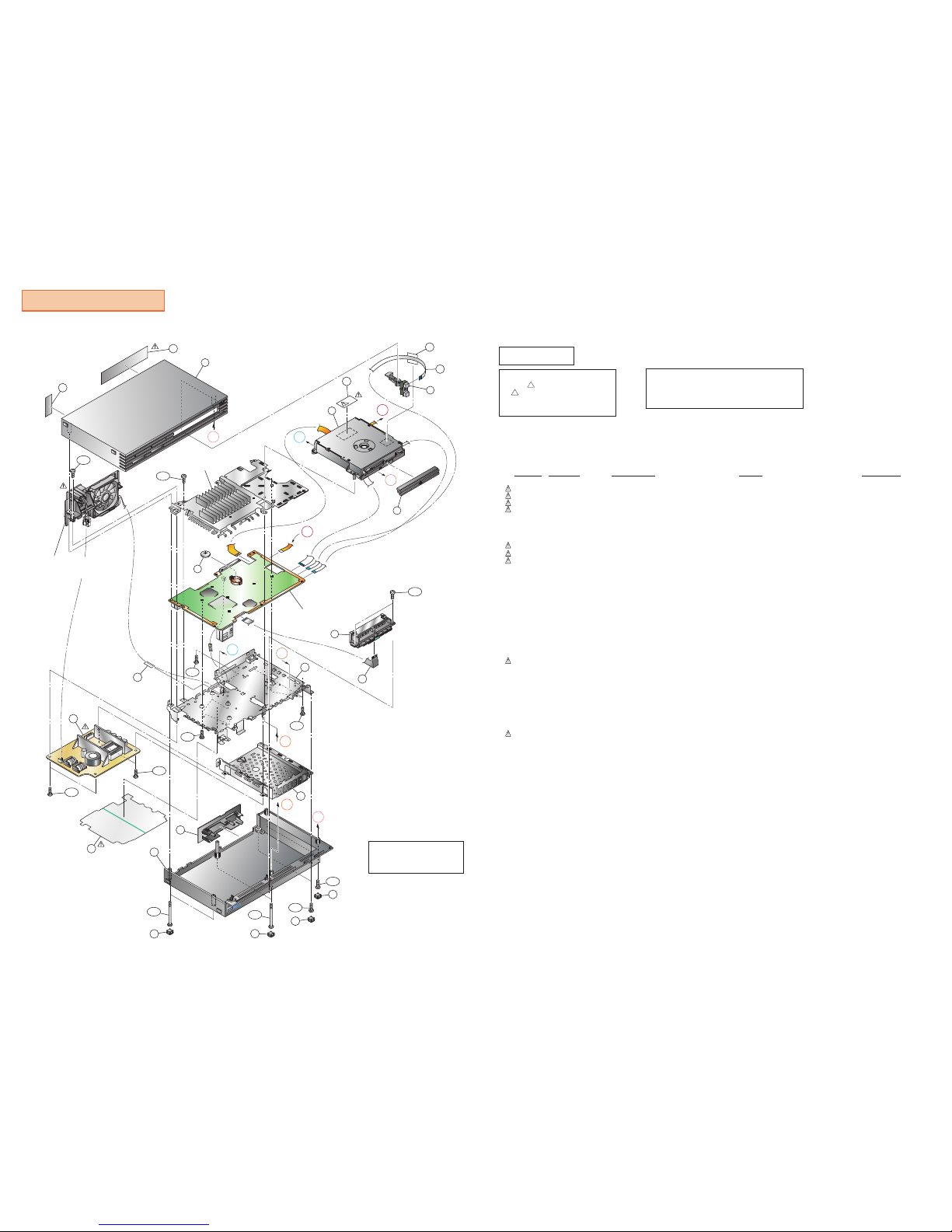
Overall and Main Block
CAUTION
Don't lose the insulating sheet
when assemble the console.
----------------------
OVERALL AND MAIN BLOCK
---------------------Ref-No. Part No. Description Remark Place code
60 1-468-605-11 POWER BLOCK
for 220-240V AC
#00
60 1-468-605-31 POWER BLOCK
for 220-240V AC
#00
60 1-468-605-21 POWER BLOCK
for 220-240V AC
#00
61 1-528-174-41 BATTERY, LITHIUM (CR2032 TYPE) #25GH
62 1-694-873-11 TERMINAL BOARD (FRONT) #17
62 1-694-874-11 TERMINAL BOARD (FRONT) #17
62 1-694-875-11 TERMINAL BOARD (FRONT) #17
71 3-072-419-01 LABEL, MODEL NUMBER (AU3)
for SCPH-30002 R F
#87
71 3-072-418-01 LABEL, MODEL NUMBER (CEK)
for SCPH-30003 R F
#87
71 3-072-417-01 LABEL, MODEL NUMBER (CEL)
for SCPH-30004 R F
#87
75 3-059-626-03 COVER, SCREW #22
76 3-059-627-01 CAP #22
84 3-067-170-01 TAPE (20X20), HARNESS STOPPER #87
91 A-6705-440-A MD BLOCK ASSY #10
92 A-6705-439-A SWITCH BLOCK ASSY #87
93 X-3951-722-2 COVER ASSY, LOWER #87
94 X-3951-721-2 COVER ASSY, UPPER #87
95 X-3951-099-1 PLATE ASSY, ORNAMENTAL #87
106 3-070-847-11 LID #87
112 3-066-498-01 TAPE, VOID #87
135 3-988-711-02 LABEL, LASER CAUTION #87
151 1-757-934-11 CABLE, FLEXIBLE FLAT (FFC-011) #12
151 1-757-934-21 CABLE, FLEXIBLE FLAT (FFC-011) #12
151 1-757-934-31 CABLE, FLEXIBLE FLAT (FFC-011)
151 1-757-934-41 CABLE, FLEXIBLE FLAT (FFC-011)
#12
156 3-071-970-01 SHIELD B (F) #16
157 3-071-971-01 SHEET, INSULATING #16
158 3-071-973-01 SHIELD HDD (F) #87
162 3-069-212-01 TAPE, HARNESS STOPPER
#87
B265 3-069-170-01 TAPPING (B2X6.5)
#87
BV312 3-325-679-21 SCREW, TAPPING +BV 3X12
#87
BV316 3-070-296-01 TAPPING +BV 3X16 #87
BV316 3-325-679-91 SCREW (2 LOCK), +BV TAPPING #87
M354 3-059-622-02 SCREW (M3X54), HEAD TAPPING #87
#87M360 3-069-168-01 TITE (CZN), M3X6 +BV S
T250 3-071-976-01 TAPPING (2X5) #87
135
E
62
61
93
76
75
76
75
M354
M354
T250
T250
B265
156
151
158
106
A
C
B
D
D
94
112
A
71
60
M360
M360
162
BV312
BV312
BV316
BV316
84
C
B
E
92
95
152
157
BV312
91
MD Block Assy
See: GH015(31/41)-8 page
Switch Block Assy
See: GH015(31/41)-10 page
Power Switch,
Fan and Rear Panel Assy Block
See: GH015(31/41)-11 page
GH Mount Block
See: GH015(31/41)-9 page
Shield (A) Assy Block
See: GH015(31/41)-9 page
152 1-823-341-11 CABLE, FLEXIBLE FLAT (FFC-015)
#12
152 1-823-341-21 CABLE, FLEXIBLE FLAT (FFC-015)
152 1-823-341-51 CABLE, FLEXIBLE FLAT (FFC-015)
#12
#12
#12
EXPLODED VIEWS
Reproduction Prohibited
SCPH-30000 R series
F-type model
— GH015(31/41)-8 —
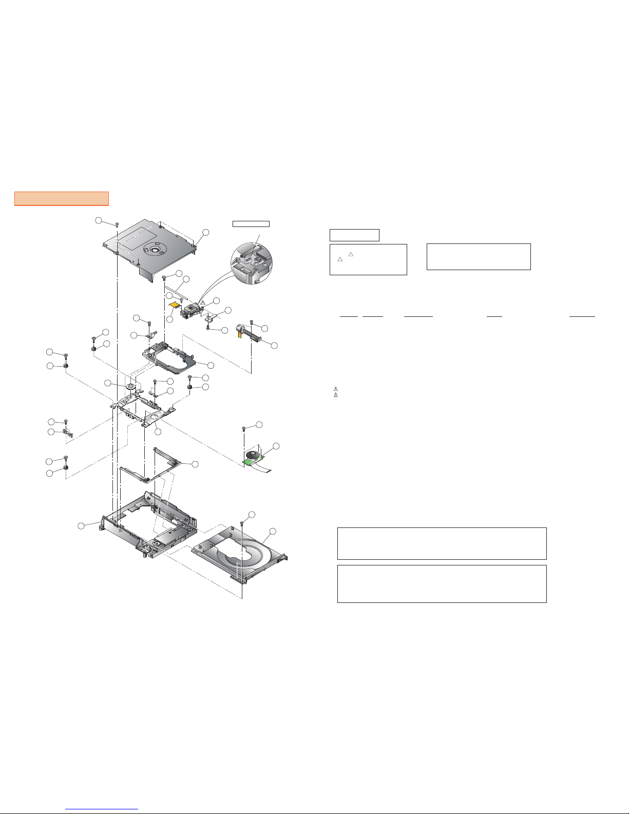
MD Block
--------
MD BLOCK
-------Ref-No. Part No. Description Remark Place code
2 1-763-700-21 MOTOR, DC (SPINDLE) #10SP
3 1-763-639-21 MOTOR, DC(SLED)
#10
#10
5 3-059-845-01 SCREW (B2X6.5), SHAFT RETAINER
#107 X-3951-637-1 FRAME ASSY, SUB
#108 3-065-277-01 INSULATOR
#109 3-065-276-01 SCREW, STEP
#1010 3-071-957-01 CHASSIS, MAIN
#1013 3-059-854-02 SHAFT, MAIN
#1014 3-059-855-02 RACK
#1016 3-060-399-01 SCREW, SKEW
#1017 3-060-400-01 TAPPING (B2X6.5)
#1022 3-062-728-01 0 PLATE 3 MAIN M2X3.2
#10
23 1-758-717-11 DEVICE, OPTICAL SF-HD7
Made by Sanyo(Not supply)
#10OP
23 8-820-151-01 DEVICE, OPTICAL KHS-400C
Made by Sony
#10OP
26 X-3952-057-1 CHASSIS ASSY, SUB
#1027 X-3952-059-1 BRACKET ASSY, PULLEY
28 X-3952-060-1 TRAY ASSY #10TR
30 X-3952-058-1 FRAME ASSY, MAIN #10
31 1-680-370-21 PWB, FLEXIBLE #10
32 3-068-075-02 SCREW (SUB), STEP #10
33 3-071-965-01 CAM, TILT #10
34 3-071-966-01 SPRING (TILT), LEAF #10
35 3-065-282-01 GUIDE (L) #10
36 3-065-283-01 GUIDE (R) #10
37 3-065-557-01 SCREW (M2X6.0) #10
EEPROM DATA is different between optical device made by Sony and made by
Sanyo.EEPROM DATA have to rewrite BASED ON replacing OPTICAL DEVICE.
The components identified by
mark ! or dotted line with mark.
! are critical for safety.
Replace only with part number
specified.
CAUTION :
Use of controls or adjustments or performance
of procedures other than those specified herein
may result in hazardous radiation exposure.
CAUTION
17
9
8
9
8
30
7
32
8
17
28
2
22
37
35
13
33
5
27
8
32
26
22
36
BOTTOM VIEW
14
22
23
17
3
16
31
22
34
10
TAP
Solder off the TAPs
after OPTICAL DEVICE
assembled in.
OPTICAL DEVICE is very delicate to static electricity.
Be carefill for handling of it not to discharge static electricity
from your body or etc. to OPTICAL DEVICE.
CAUTION :
CAUTION :
Reproduction Prohibited
SCPH-30000 R series
F-type model
— GH015(31/41)-9 —
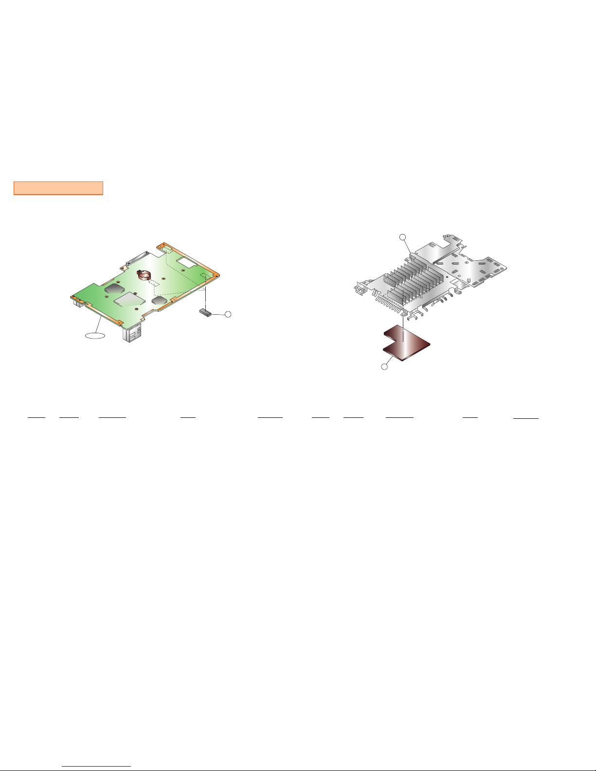
GH Mount Block
--------------
GH MOUNT BLOCK
-------------Ref-No. Part No. Description Remark Place code
87 3-068-806-02 SHEET (DRIVER), ELECTRIC HEAT #87
GH015
A-6714-504-A
A-6715-504-A GH-015(31/41) COMPL
GH-015(31/41) MOUNT
for SCPH-30002 R
#25GH
#25GHGH015 A-6715-505-A
A-6714-505-A
GH-015(31/41) COMPL
GH-015(31/41) MOUNT
for SCPH-30003 R /-30004 R
Shield (A) Assy Block
---------------------
SHIELD (A) ASSY BLOCK
--------------------Ref-No. Part No. Description Remark
Place code
9797X-3952-061-1
X-3952-256-1
SHIELD A (F) ASSY
SHIELD A ASSY (F) #87
#87
120 3-059-652-01 SHEET (A), ELECTRIC HEAT #87
87
GH015
97
120
 Loading...