

Sony PCMR-700 Service manual
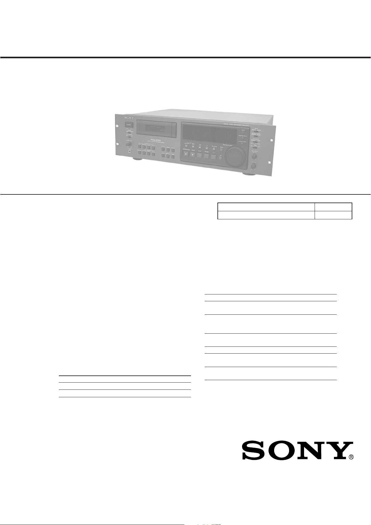
PCM-R700
SERVICE MANUAL
Ver 1.1 2002.01
SPECIFICATIONS
Recording section
T ape Digital audio tape
Recording head Rotary head
Recording time Standard: 120 minutes
Long-play: 240 minutes
(DT-120)
Tape speed Standard: 8.15 mm/s
Long-play: 4.075 mm/s
Drum rotation Standard: 2,000 rpm
Long-play: 1,000 rpm
Error correction Double-encoded Reed Solomon code
Tape section
Track pitch 13.6 µm (20.4 µm)
Sampling frequency 48 kHz, 44.1 kHz, 32kHz
Modulation system 8-10 modulation
Transfer rate 2.46 Mbit/sec
Number of channels 2 channels, stereo
D/A conversion Standard: 16-bit linear
(quantization) Long-play: 12-bit non-linear
General section
Power requirements
Where purchased Power requirements
U.S.A./Canada 120 V AC, 60 Hz
Europe/U.K. 230 V AC, 50/60 Hz
US Model
Canadian Model
AEP Model
UK Model
Model Name Using Similar Mechanism PCM-2800
T ape Transport Mechanism Type
Remote commander RM-D757 (supplied)
Remote control system Infrared control
Power requirements 3 V DC, with two size-AA (R6) batteries
Dimensions Approx 45 × 210 × 26 mm (w/h/d)
Weight Approx 100 g (3.5 oz) incl. batteries
Input connectors
Analog Input
Connector Type Input impedance Rated input level
ANALOG Phono(UNBALANCE) plug jack
ANALOG XLR-3
(BALANCE) (FEMALE)
Digital Input
Connector Type Input impedance Rated input level
AES/EBU
COAXIAL
13
/16 × 83/8 × 11/16 inches)
(1
47 kilohms –12 dBs
10 kilohms
or more
(balanced)
XLR-3 110 ohms
(FEMALE)(balanced)
Phono-plug
jack
75 ohms 0.5 Vp-p
+4 dBs
(factory setting)
–
– Continued on next page –
DATM-58
a)
Power consumption 34 W
Dimensions Approx 482 × 145 × 355 mm (w/h/d)
Weight Approx 7.3 kg (16 Ib 2 oz)
9-960-914-12 Sony Corporation
2002A0500-1 Home Audio Company
C 2002.1 Published by Sony Engineering Corporation
3
/4 × 14 inches)
(19 × 5
(not including rack mount adaptor)
DIGITAL AUDIO TAPE DECK
Output connectors
Analog Output
Connector Type
ANALOG Phono-plug
(UNBALANCE) jack
ANALOG XLR-3 100 ohms
(BALANCE) (MALE) (balanced)
PHONES
Digital Output
Connector Type
AES/EBU
COAXIAL
Variable range of analog (BALANCE) input/output reference level
Maximum analog (BALANCE) output level
Remote switch connectors
Audio characteristics
Frequency response
Signal-to-noise ratio
Totalhar monic distortion
Wow and flutter Below measurable limit (± 0.001 % W.
a) The reference lebel corresponds to –20 dB on the peak level meters.
b) During analog input sith the SBM function off
Supplied accessories AC power cord (1)
Stereo phoneplug jack
XLR-3 35 ohms
(MALE) (balanced)
Phono-plug
jack
b)
b)
Output
impedance
1 kilohm –12 dBs 47 kilohms
100 ohms 0.36 mW 32 ohms
Output
impedance
75 ohms 0.5V p-p 75 ohms
+4 dBs to –12 dBs
+24 dBs
DIN connector (8-pin, parallel)
Monaural minijack (serial)
Standard: 20-20,000 Hz (±0.5 dB)
Long-play: 20-14,500 Hz (±0.5 dB)
90 dB or more
(20 kHz LPF, A-weight filter ON)
b)
Standard: 0.05% or less
Long-play: 0.3% or less
(1 kHz, Reference level
ON)
PEAK)
Remote commander (remote) RM-D757
(1)
Size-AA (R6) batteries (2)
Screws (M5 × 12) (4)
Decorative washers (4)
Operating instructions (1)
Warranty card (U.S.A. and Canadian
models only) (1)
Rated
output
level
+4 dBs
(factory
setting)
Rated
output
level
– 110 ohms
Load
impedance
a)
10 kilohms
or more
Load
impedance
a)
20 kHz LPF
SERVICING NOTES
Flexible Circuit Board Repairing
• Keep the temperature of the soldering iron around 270 ˚C during
repairing.
• Do not touch the soldering iron on the same conductor of the
circuit board (within 3 times).
• Be careful not to apply force on the conductor when soldering or
unsoldering .
Notes on chip component replacement
• Never reuse a disconnected chip component.
• Notice that the minus side of a tantalum capacitor may be dam-
aged by heat.
CAUTION
Danger of explosion if battery is incorrectly replaced.
Replace only with the same or equivalent type recommended by the
manufacturer.
Discard used batteries according to the manufacturer’ s instructions.
ADV ARSEL!
Lithiumbatteri-Eksplosionsfare ved fejlagtig håndtering.
a)
Udskiftning må kun ske med batteri
af samme fabrikat og type.
Levér det brugte batteri tilbage til leverandøren.
ADVARSEL
Eksplosjonsfare ved feilaktig skifte av batteri.
Benytt samme batteritype eller en tilsvarende type
anbefalt av apparatfabrikanten.
Brukte batterier kasseres i henhold til fabrikantens
instruksjoner.
VARNING
Explosionsfara vid felaktigt batteribyte.
Använd samma batterityp eller en ekvivalent typ som
rekommenderas av apparattillverkaren.
Kassera använt batteri enligt fabrikantens instruktion.
VAROITUS
Paristo voi räjähtää, jos se on virheellisesti asennettu.
Vaihda paristo ainoastaan laitev almistajan suosittelemaan tyyppiin.
Hävitä käytetty paristo valmistajan ohjeiden mukaisesti.
MODEL IDENTIFICATION
– Model Number label (Printed in Back Panel) –
MODEL NO. PCM-R700
DIGITAL AUDIO RECORDER
Design and specifications are subject to change without notice.
US, Canadian model : AC 120 V 60 Hz 34 W
AEP, UK Model : AC 230 V
– 2 –
⁄
50/60Hz 34 W

SAFETY CHECK-OUT
After correcting the original service problem, perform the following safety check before releasing the set to the customer:
Check the antenna terminals, metal trim, “metallized” knobs, screws,
and all other exposed metal parts for AC leakage. Check leakage as
described below.
LEAKAGE TEST
The AC leakage from any exposed metal part to earth ground and
from all exposed metal parts to any exposed metal part having a
return to chassis, must not exceed 0.5 mA (500 microampers). Leakage current can be measured by any one of three methods.
1. A commercial leakage tester, such as the Simpson 229 or RCA
WT-540A. Follow the manufacturers’ instructions to use these
instruments.
2. A battery-operated AC milliammeter. The Data Precision 245
digital multimeter is suitable for this job.
3. Measuring the voltage drop across a resistor by means of a V OM
or battery-operated A C voltmeter. The “limit” indication is 0.75
V, so analog meters must have an accurate low-voltage scale.
The Simpson 250 and Sanwa SH-63Trd are examples of a passive VOM that is suitable. Nearly all battery operated digital
multimeters that have a 2 V AC range are suitable. (See Fig. A)
To Exposed Metal
Parts on Set
TABLE OF CONTENTS
1. GENERAL
..................................................................... 4
2. DISASSEMBLY............................................................ 18
3. ADJUSTMENTS.......................................................... 22
4. DIAGRAMS
4-1. Block Diagrams
– Digital Audio Section – .................................................. 29
– Analog Audio Section –.................................................. 31
– System Control Section – ............................................... 33
– Power Section – .............................................................. 35
4-2. Printed Wiring Board – RF Section – ................................ 40
4-3. Schematic Diagram – RF Section –................................... 43
4-4. Printed Wiring Boards – MD Section –............................. 46
4-5. Schematic Diagram – MD Section – ................................. 49
4-6. Printed Wiring Boards – DIGITAL Section – ................... 53
4-7. Schematic Diagram – DIGITAL Section –........................ 57
4-8. Schematic Diagram – AUDIO Section – ........................... 61
4-9. Printed Wiring Boards – AUDIO Section –....................... 65
4-10. Printed Wiring Boards – DISPLAY Section –................... 69
4-11. Schematic Diagram – DISPLAY Section – ....................... 73
4-12. IC Pin Function Description .............................................. 76
5. EXPLODED VIEWS ................................................... 88
0.15 µF
1.5 k
Ω
Earth Ground
AC
voltmeter
(0.75 V)
Fig. A. Using an AC voltmeter to check AC leakage.
SAFETY-RELATED COMPONENT WARNING!!
COMPONENTS IDENTIFIED BY MARK ! OR DOTTED
LINE WITH MARK ! ON THE SCHEMATIC DIA GRAMS
AND IN THE PARTS LIST ARE CRITICAL TO SAFE
OPERATION. REPLACE THESE COMPONENTS WITH
SONY PARTS WHOSE PART NUMBERS APPEAR AS
SHOWN IN THIS MANU AL OR IN SUPPLEMENTS PUBLISHED BY SONY.
6. ELECTRICAL PARTS LIST .................................... 96
ATTENTION AU COMPOSANT AYANT RAPPORT
À LA SÉCURITÉ!
LES COMPOSANTS IDENTIFIÉS P AR UNE MARQUE !
SUR LES DIAGRAMMES SCHÉMA TIQUES ET LA LISTE
DES PIÈCES SONT CRITIQUES POUR LA SÉCURITÉ
DE FONCTIONNEMENT. NE REMPLACER CES COMPOSANTS QUE PAR DES PIÈCES SONY DONT LES
NUMÉROS SONT DONNÉS DANS CE MANUEL OU
DANS LES SUPPLÉMENTS PUBLIÉS PAR SONY.
– 3 –
This section is extracted
from instruction manual.
SECTION 1
GENERAL
– 4 –
– 5 –
– 6 –
– 7 –
– 8 –
– 9 –
– 10 –
– 11 –
– 12 –
– 13 –
– 14 –
– 15 –
– 16 –
– 17 –
• This set can be dissassembled in the order shown below.
SECTION 2
DISASSEMBLY
COVER
(Page 18)
CASSETTE COMPARTMENT
MOTOR ASS’Y (M905)
(Page 20)
Note: Follow the disassembly procedure in the numerical order given.
MECHANISM DECK SECTION (DATM-58)
(Page 19)
DRUM
(Page 20)
DRUM DRIVE BOARD,
REEL MOTOR (M903)
(Page 21)
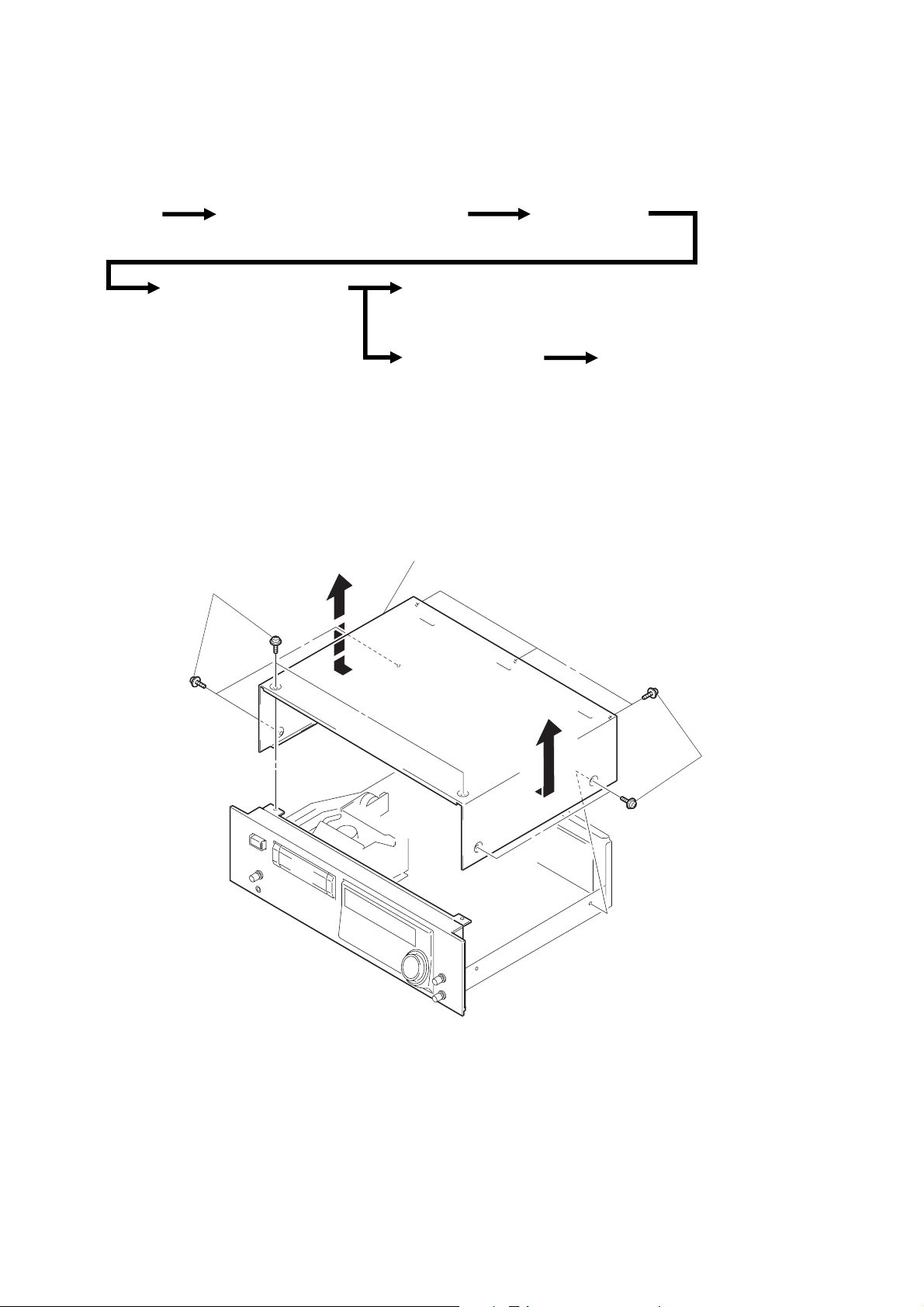
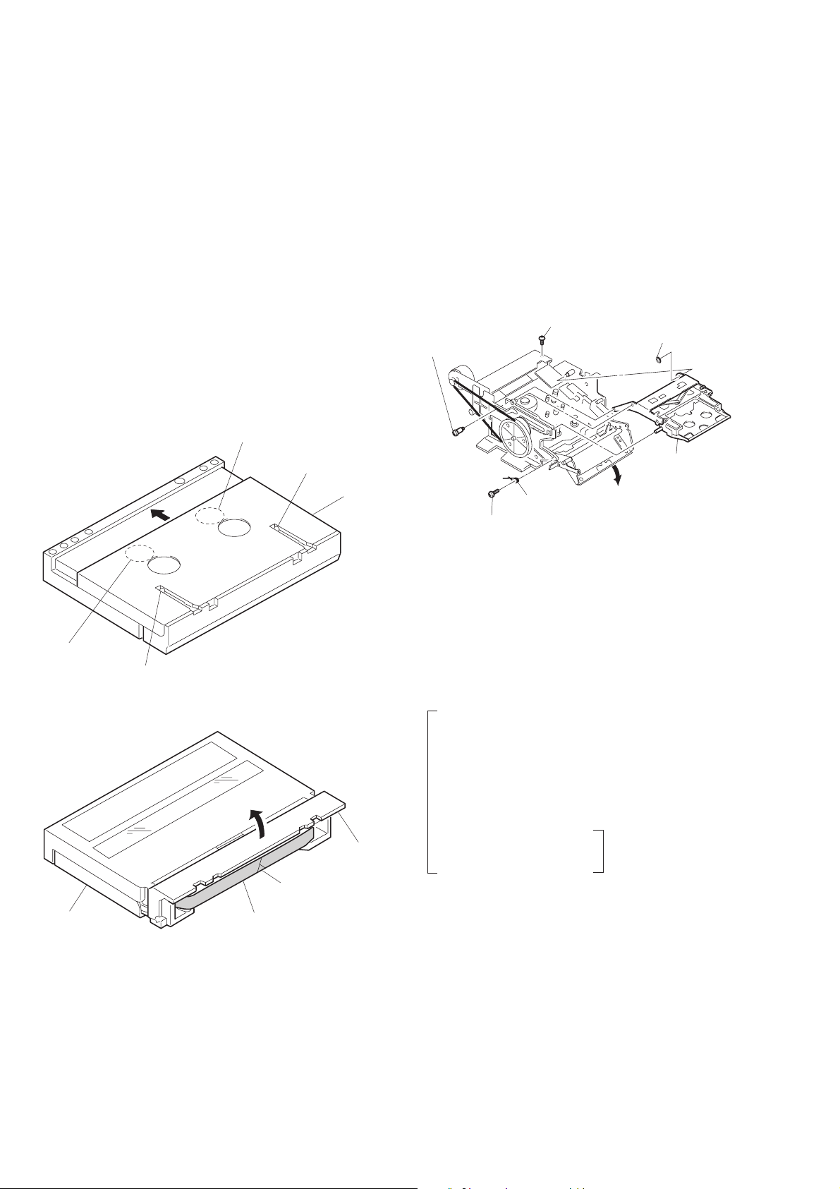
COVER
2
Remove the cover to
direction of the arrow.
1
four screws
(case) (M3
×
10)
HOLDER ASS’Y
(Page 19)
CAPSTAN MOTOR (M902)
(Page 21)
1
five screws
(case) (M3
×
10)
– 18 –
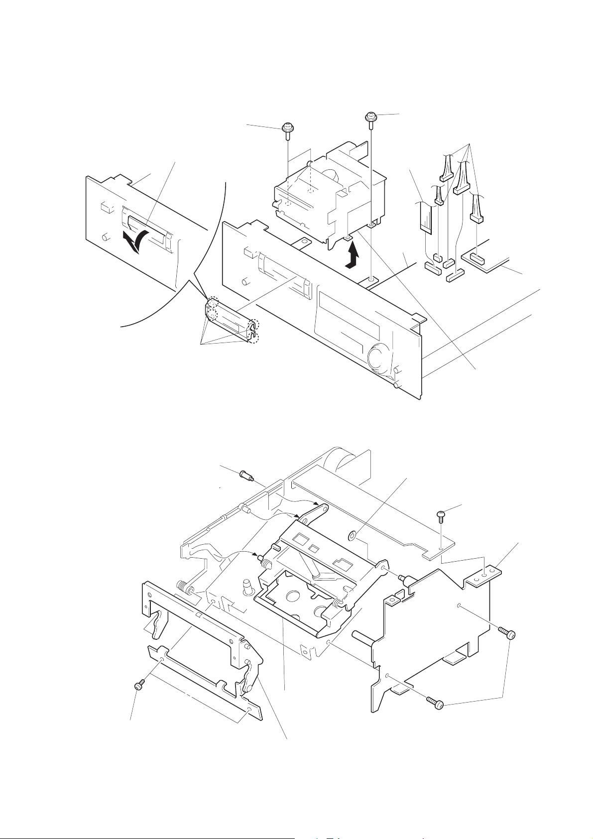
MECHANISM DECK SECTION (DATM-58)
4
1
Open the window (cassette compartment),
remove the four claws to direction
of the arrow
A
.
two screws
(PTTWH3
×
6)
4
3
wire (flat type)
(31 core)
(CN504)
two screws
(PTTWH3
×
6)
2
four connectors
(CN506, 507, 508, 802)
HOLDER ASS’Y
A
four claws
1
screw (step)
B
digital board
3
5
nylon washer
SP board
Remove the mechanism deck
section (DATM-58) to direction
of the arrow
4
screw
(BVTT3
B
.
×
6)
6
two screws
(B2
5
side plate (R) ass’y
8
holder ass’y
×
4)
7
fulcrum plate ass’y
2
two screws
(B2.6
×
4)
– 19 –
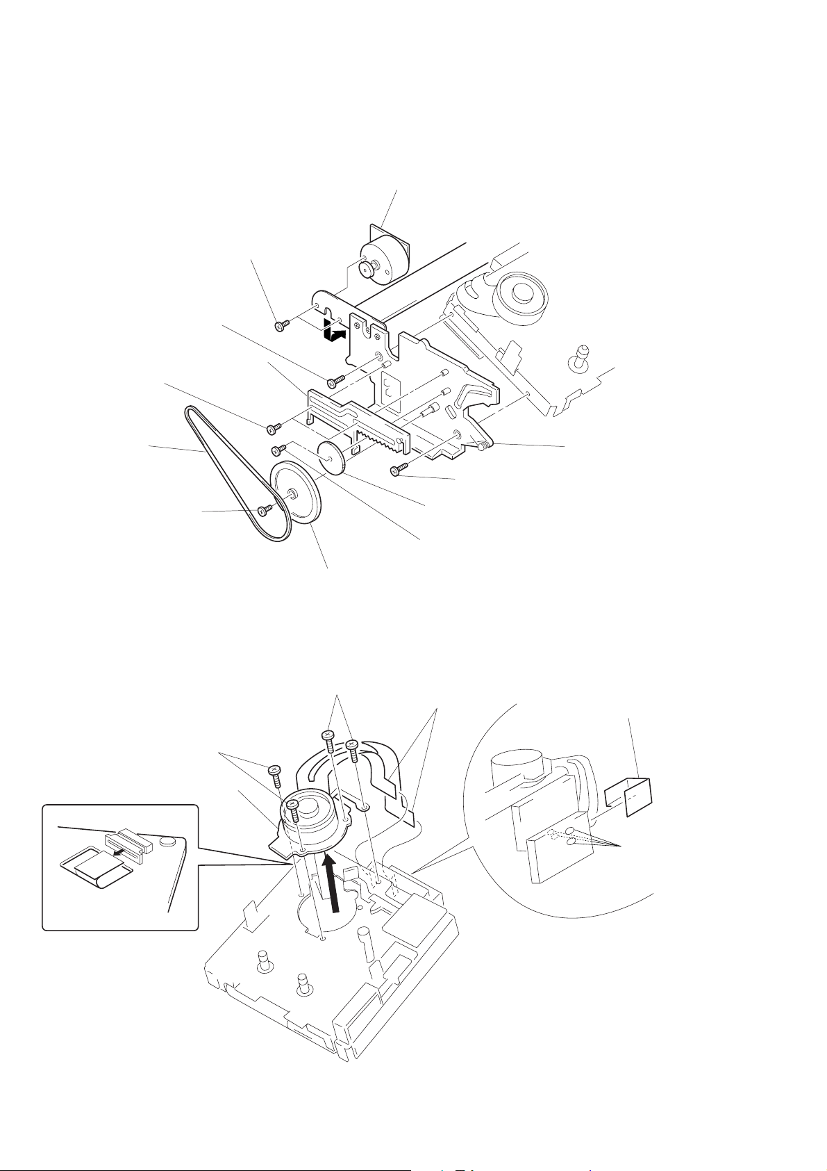
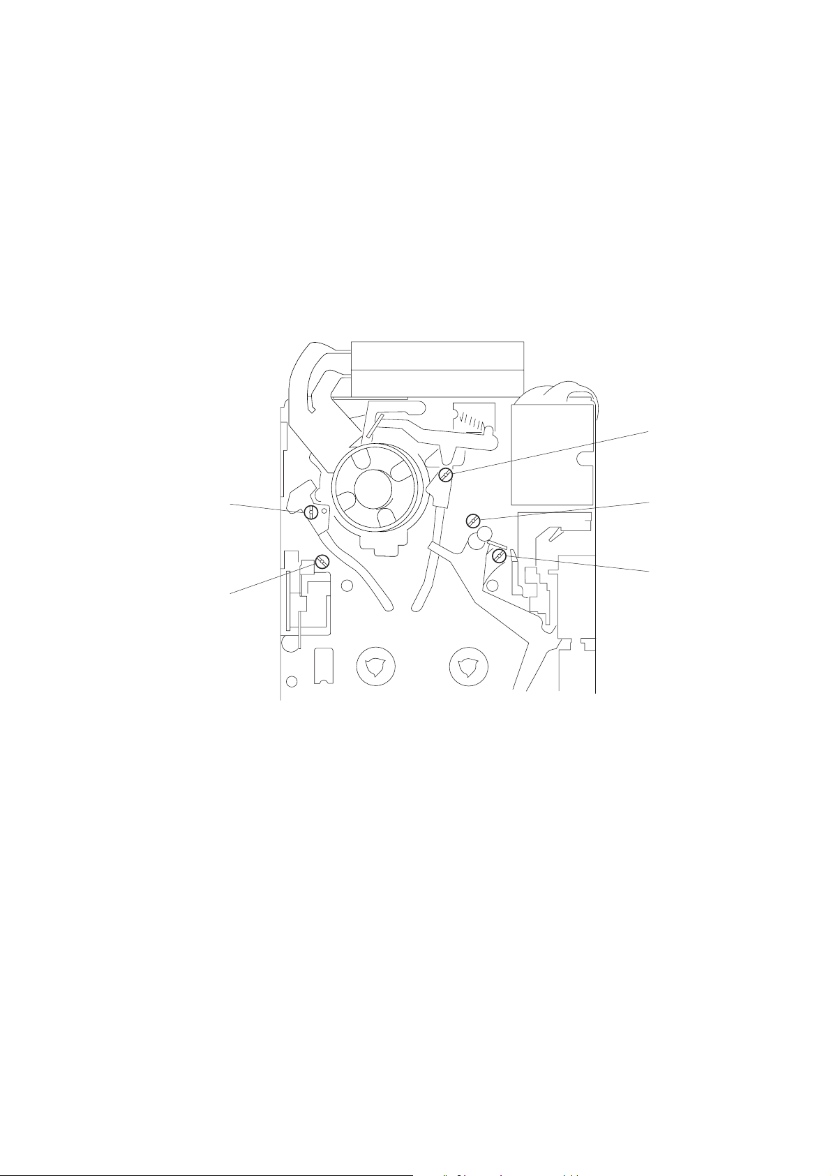
CASSETTE COMPARTMENT MOTOR ASS’Y (M905)
8
two screws
×
3)
(B2.6
0
screw
×
4)
(B2.6
7
slider ass’y
6
tapping screw
(B1.7
×
3)
1
capstan belt
2
tapping screw
(B1.7
×
3)
9
cassette compartment motor ass’y
(M905)
0
screw (B2.6 × 4)
5
driving gear
4
screw (B1.7 × 3)
!¡
chassis (L)
DRUM
4
flexible board (CN7)
5
two screws
(B 2
3
pulley
5
two screws
×
3)
(B 2
×
3)
6
drum
3
two flexible boards
(CN1, 51)
2
sheet (RF flexible)
1
Remove the four
solders of
sheet (RF flexible).
– 20 –
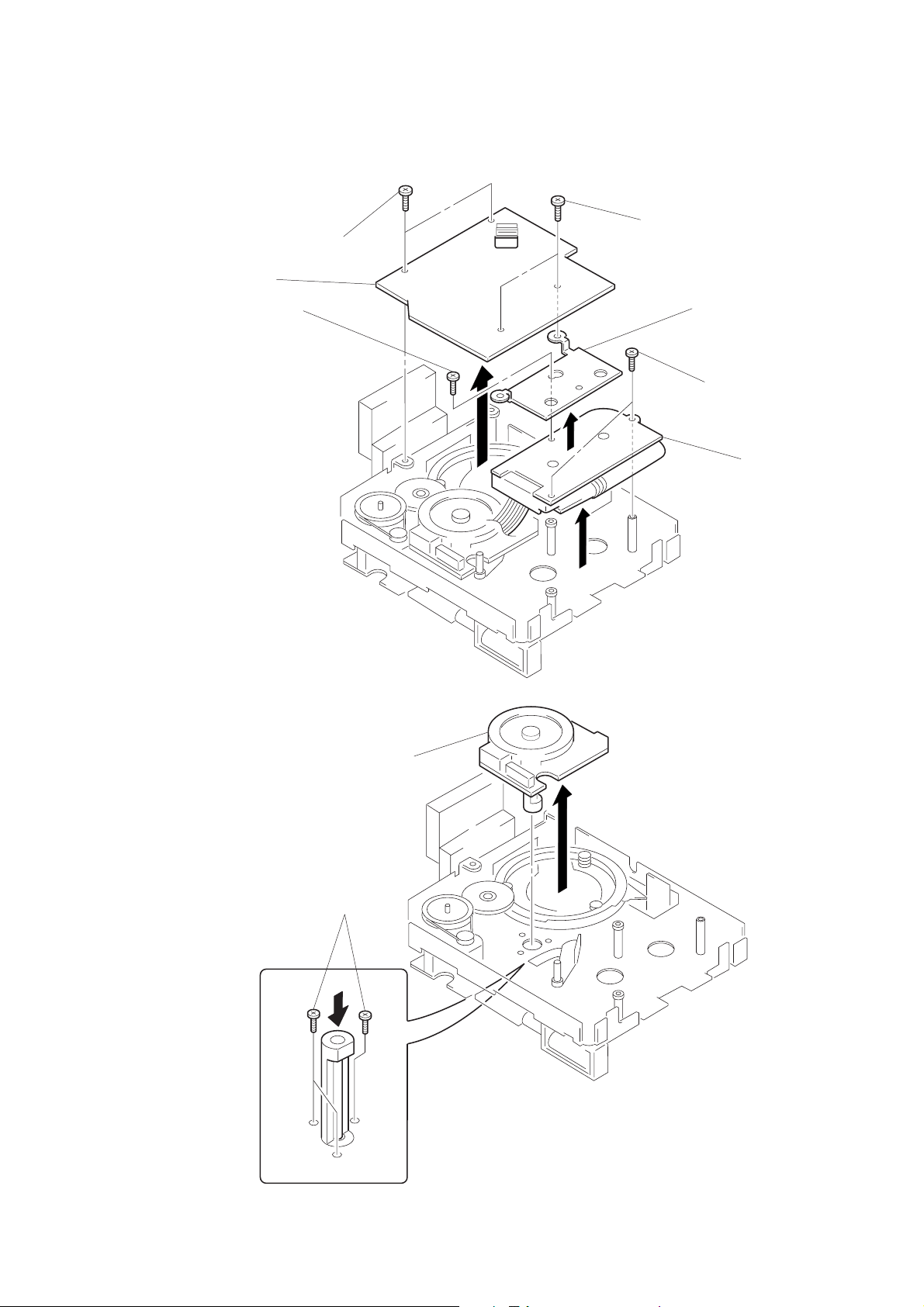
DRUM DRIVE BOARD, REEL MOTOR (M903)
1
two screws
×
3)
(B2
2
drum drive board
3
screw
(B2
×
3)
1
two screws
(B2
×
3)
4
bracket (MD PC board)
5
two screws
×
3)
(B2
6
reel motor (M903)
CAPSTAN MOTOR (M902)
2
capstan motor
(M902)
1
three screws
(P1.7
×
4)
– 21 –
SECTION 3
ADJUSTMENTS
PRECAUTION
1. The adjustments are performed in the sequence that they are
described.
2. The required test tapes are:
TY-7111 (8-909-812-00) ................................. Level
TY-7252 (8-909-822-00) ................................. Tracking
TY-7551 (8-909-814-00) ................................. Function
TY-30B (8-892-358-00)................................... Blank
The required torque meter is:
TW-7131 (8-909-708-71) ................................ FWD
3. Switch and Control Settings
REMOTE switch : OFF
REC MODE switch : 48k (STANDARD)
REC LEVEL control : Minimum
PHONE LEVEL control : Minimum
4. Preparation of End Sensor Cassette
(1) Push the slider locks of a cassette tape and slide the slider in
the direction of the arrow.
hub hole
slider lock
slider
6. When adjusting tape pass and each guide, as shown below, it is
a good practice to remove the holder assy and use the DAT cassette holder (J-8000-002-A). This facilitates adjustment work.
• When removing and installing the holder assy, turn the pulle y
counterclockwise and set loading OUT condition for easy removal and installation.
• When adjusting, turn the pulley clockwise and turn on the
CASSETTE TABLE IN switch (S2) to set loading IN condition. Then, set the test tape.
1
6
Step screw
2
BVTP 3 × 6
3
Cassette
spring
BVTT 3 × 8
4
5
Nylon washer
7
Cassette
holder assy
Push down the holder
in the direction
hub hole
slider lock
(2) Open the cassette lid and cut tape.
cassette lid
cut tape
slider
tape
(3) Turn the hubs to take-up tape (for both T and S sides).
The end sensor cassette tape for end sensor adjustment is
now prepared.
5. Tak e care nev er to turn RV1 and RV2 within the RF AMP board
of the cassette compartment section.
7. Test Mode
• To enter the test mode , short between TP (MAIN-TEST) and
the GND on the DIGIT AL board, then turn on the po wer . The
meter scale within the fluorescent indicator tube (FL701) will
flash.
Press the OPEN/CLOSE 6 key and set the test tape. (The
specified tape should be used for each adjustment.)
Test Mode (Short between TP (MAIN-TEST) and GND)
1 Have “DPG” display lit in the fluorescent indicator tube.
(Press the AMS + key.)
• S2, T2 and F Guide Adjustments
• End Sensor Adjustment
• Tape Pass Fine Adjustment (×1.5FWD mode)
• DPG Adjustment
2 Have “TR” display lit in the fluorescent indicator tube.
(Press the ” key.)
• FWD Torque Adjustment
• FWD Back Tension
(Torque measurement mode)
Adjustment
• To release the test mode, r emove the short between TP (MAIN-
TEST) and GND. After necessary adjustment is completed,
be sure to release the test mode.
– 22 –
8. After adjustment is completed, perform the following checks to
verify the tape speed.
(1) Check that with the REC MODE switch set to ST AND ARD
48k, tape is normally recorded and played back. (×1)
(2) Check that with the REC MODE switch set to LONG, tape
is normally recorded and played back. (×0.5)
(3) Check that in performing the CUE (” + )) or REVIEW
(” + 0) operation, “kyur kyur” sound is heard. (×3, ×8)
Adjustment Location: mechanism deck block
(4) Check that after performing the FF ( )) or REW (0)
operation, the time display is appropriate. (×16)
(5) Chec k that the AMS (+, =) operation is normal.
T1 guide
S1 guide
S2 guide
T2 guide
F guide
– 23 –

3-1. MECHANICAL ADJUSTMENTS
When replacing any drum related parts, after S2, T2 and F guide
adjustments have been made, tape pass fine adjustment (×1.5FWD
mode) in Electrical adjustment should be performed.
S2, T2 and F Guide Adjustments
Adjustment Method:
1. Enter the Test Mode 1 (see page 22.) and set the test tape TY-
7252 (8-909-822-00).
2. Set the REC MODE switch to STANDARD 48k and press the
AMS + key.
While in FWD mode, check that there is no curl on the upper
and lower flanges of the S2, T2 and F guides.
If any curl is present, put the S2, T2 and F guide of concern
back in the high position and adjust by adjusting the direction
of tightening.
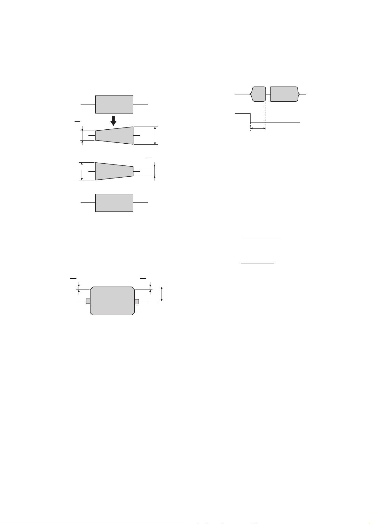
*
What is curl?
Curl
Distortion that occurs on
tape during FWD operation.
3-2. ELECTRICAL ADJUSTMENTS
End Sensor Adjustment
When removing the holder assy and when replacing the mechanism
deck block, this adjustment should be performed.
Adjustment Method:
1. Connect the CH-1 terminal of an oscilloscope to TP (S-END)
and the CH-2 terminal to TP (T-END) on the DIGITAL board.
2. Enter the Test Mode 1 (see page 22.) and set the end sensor
cassette tape (see page 22.)
3. Set the STOP (p) mode.
4. Adjust RV502 (S-END) and RV501 (T-END) on the DIGITAL
board so that the respective peak to peak values of the waveforms on the oscilloscope are 1.2 Vp-p.
FWD Back Tension Adjustment
Adjustment Method:
1. Enter the T est Mode 2 (Torque Measurement Mode) (see page
22.) and set the torque meter TW-7131 (8-909-708-71).
2. Press the PLAY (”) key.
3. Press the AMS + key or = key and adjust so tha t the back
tension (S side) is within the range of 8.5 ± 0.5 g•cm.
4. When the torque meter is circulating around, check the indicated value.
5. Verify that the maximum value is less than 19.5 g•cm.
REV Torque Check and REV Back Tension Check
Check Method:
1. After FWD torque adjustment and FWD back tension adjustment are completed, press the PLA Y (”) ke y again and set REV
(“) mode.
2. Check that the REV torque value is within the range of 13.5 to
17.5 g•cm and that the REV back tension value is within the
range of 7.5 to 11.5 g•cm.
Tape Pass Fine Adjustment (×1.5FWD Mode)
When replacing any drum related parts, be sure to perform this adjustment.
Adjustment Method:
1. Connect the CH-1 terminal of an oscilloscope to TP (RF) and
the CH-2 terminal to TP (SWP) on the DIGITAL board.
2. Enter the Test Mode 1 (see page 22.) and set the test tape TY7252 (8-909-822-00).
3. Press the AMS (+) key.
Role of each switch in test mode.
OFFSET
–0 +
WIRED OFF
WIRELESS
ATF : ON
STANDARD LONG
ATF : OFF
1.2Vp-p
Adjustment Location: See page 26.
FWD T orque Adjustment
Adjustment Method:
1. Enter the Test Mode 2 (Torque Measurement Mode) (see page
22.) and set the torque meter TW-7131 (8-909-708-71).
2. Press the PLAY (”) key.
3. Press the ) key or 0 key and adjust so that the FWD torque
value (T side take-up torque) is within the range of 11 to 13
g•cm.
4. When the torque meter is circulating around, check the indicated value.
48k 44.1k
REMOTE REC MODE
4. Put the REC MODE switch to the LONG (ATF: OFF) position
and put the REMOTE switch to either the WIRED or WIRELESS position (OFFSET: – or +), fine adjust both the S1 guide
and T1 guide so that the RF signal waveform of the oscilloscope repeatedly contracts and expands in vertical directions as
it has the same shape.
* Adjust the direction of tightening to complete this adjustment.
If there is curl on any of the upper and lower flanges of the
S2, T2 and F guides, adjust the guide of concern.
– 24 –
5. Put the REC MODE switch to the ST AND ARD 48k (ATF: ON)
s
P
position and put the REMOTE switch to either the WIRED or
WIRELESS position (OFFSET: – or +), then check the RF signal waveform.
4
A or less
5
4
A’ or les
5
A
NG
NG
OK
A'
6. Put the REC MODE switch to the ST AND ARD 48k (AFT : ON)
position and put the REMOTE switch to the OFF position (OFFSET: 0), then check the RF signal waveform.
(1) Verify that the peak value (B) of the RF signal waveform is
60mV or more.
(2) Verify that the flat position of the RF signal waveform has
undershoots of 10% or less.
B
10
or less
10
B
or less
B
Check that there is a difference of 650 ± 15 µsec between the
oscilloscope’s SWP signal and the RF signal.
RF
SW
650±15 µsec
Adjustment Location: See page 26.
CHECK AND REPLACEMENT FOR DATE FNCTION
Clock IC Back-up Check
• When replacing the lithium battery (BATT501) or replacing any
of the clock IC (IC518) and peripheral parts, the clock will be
reset.
(The DATE display will be [‘-- -- --] [-[PRESENT] button is pushed.)
] even when the
h--m--s
Perform the back-up check by the following procedure.
(1) Connect a DC voltmeter between the DIGITAL board’s TP
(BATT+) as (+) side on the TP (BATT–) as (–) side.
(2) With the PO WER switch of the set OFF, check that the v olt-
age (1) is
less than +20 mV.
(If the measured value is more than +20 mV, inspect the IC518
and peripheral parts and replace as needed.)
(3) With the POWER switch of the set ON, check that the volt-
age (1) is
less than 0 mV (minus indication), (If plus indication, inspect the D510 and peripheral parts and replace as
needed.)
(4) When these voltages are normal, set the clock to the current
date and time according to the instruction manual.
(year/month/day/day of week/hours/minutes/seconds)*
(5) After the clock is set in item (4), turn off the POWER switch
once and in several seconds, turn on the power again and
make sure that the clock is operating.
7. If any of the specified values are not satisf ied, repeat items 3 to
6.
Adjustment Location: See page 23.
DPG Adjustment
When replacing any drum related parts, be sure to perform this adjustment.
Adjustment Method:
1. Connect the CH-1 terminal of an oscilloscope to TP (RF) and
the CH-2 terminal to TP (SWP) on the DIGITAL board.
2. Enter the Test Mode 1 (see page 22.) and set the test tape TY7252 (8-909-822-00).
3. Put the REC MODE switch to the ST AND ARD 48k (ATF: ON)
position and put the REMOTE switch to the OFF position (OFFSET: 0).
4. Press the AMS (+) key.
5. Press the PLAY (”) key.
6. “DPG OK” is displayed in the fluorescent indicator tube.
Adjustment Location: See page 26.
– 25 –
Replacement of Back-up Battery
The back-up battery for clock is designed to serve for more than
seven years under normal service conditions (room temperature and
ordinary humidity).
When replacing the battery, take note of the following:
• Perform the above “Clock IC Back-up Check” and remedy the
cause of battery consumption.
• The open voltage of the battery as removed is 3.0 V or more when
it is new. If this voltage is 2.0 V or less, then battery is fully consumed and needs to be replaced.
• After the battery is replaced, perform the “Clock IC Back-up
Check” again and set the clock.
• The coin type lithium battery (CR2032) is used for replacement.
* For description of the clock setting, see page 6.
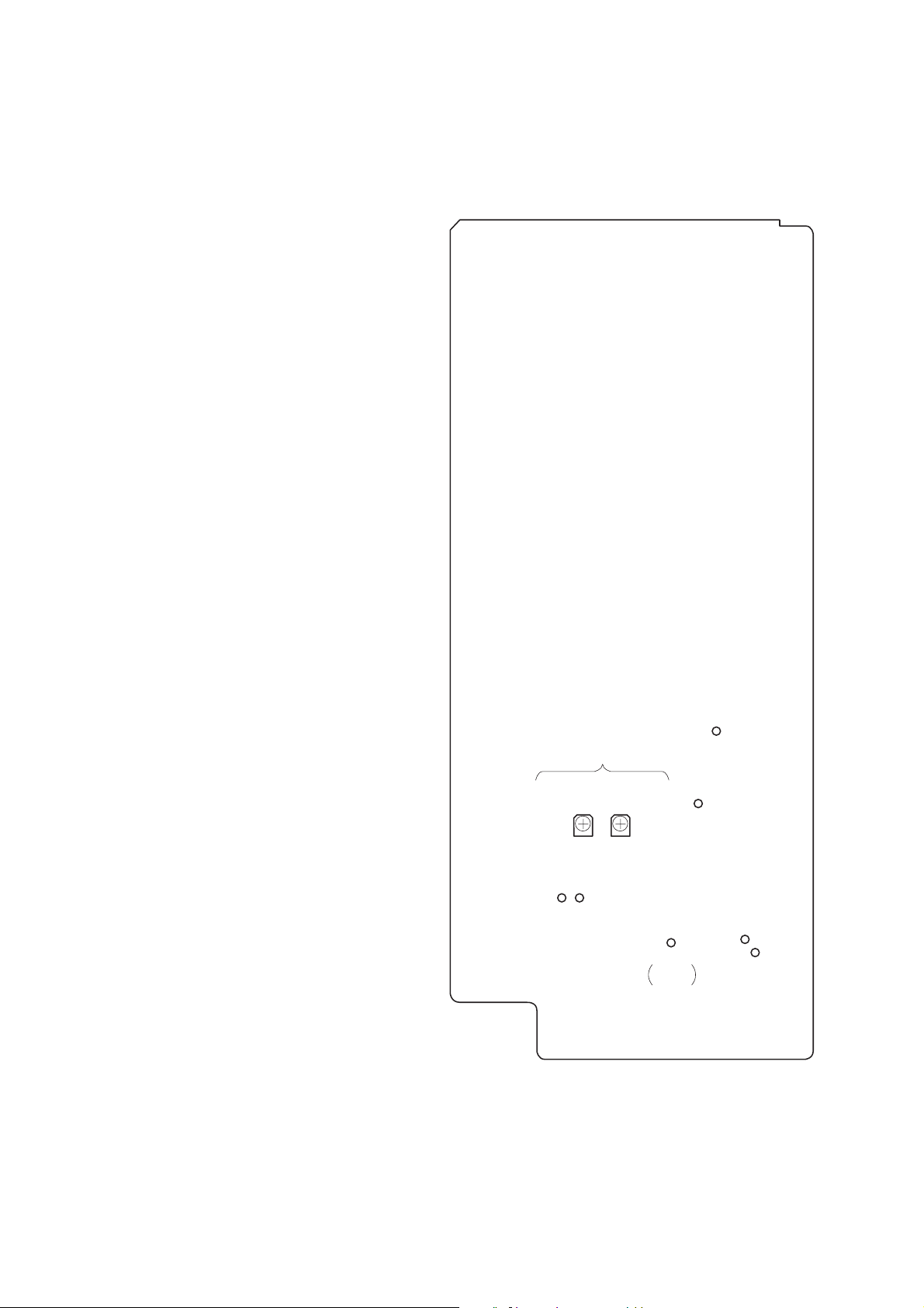
Adjustment and Check Locations :
DIGITAL board – component side –
END SENSOR ADJ
(S-END)
RV502
TP
(S-END)
(T-END)
RV501
TP
(T-END)
TP
MAIN–
TEST
TP
(RF)
TP
(SWP)
TP
(BATT+)
TP
(BATT–)
– 26 –
 Loading...