

Sony PCMR-300 Service manual
PCM-R300
SERVICE MANUAL
Ver 1.1 2001. 06
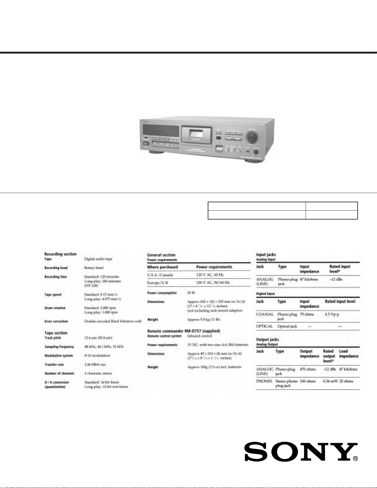
SPECIFICATIONS
Canadian Model
Model Name Using Similar Mechanism
T ape T r ansport Mechanism T ype
US Model
AEP Model
UK Model
DTC-A6
DATM-110A
9-922-708-12
2001F0200-1
© 2001.6
– Continued on next page –
DIGITAL AUDIO RECORDER
Sony Corporation
Home Audio Company
Shinagawa Tec Service Manual Production Group
– 1 –
Notes on chip component replacement
• Never reuse a disconnected chip component.
• Notice that the minus side of a tantalum capacitor may be
damaged by heat.
MODEL IDENTIFICATION
— Back Panel —
Parts No.
3-018-941-0π : US, Canadian model
3-018-941-1π : AEP, UK model
SAFETY-RELATED COMPONENT WARNING !!
COMPONENTS IDENTIFIED BY MARK ! OR DOTTED LINE
WITH MARK ! ON THE SCHEMATIC DIAGRAMS AND IN
THE PARTS LIST ARE CRITICAL TO SAFE OPERATION.
REPLACE THESE COMPONENTS WITH SONY PARTS
WHOSE PART NUMBERS APPEAR AS SHOWN IN THIS
MANUAL OR IN SUPPLEMENTS PUBLISHED BY SONY.
ATTENTION AU COMPOSANT AYANT RAPPORT
À LA SÉCURITÉ!!
LES COMPOSANTS IDENTIFIÉS P AR UNE MARQUE ! SUR
LES DIAGRAMMES SCHÉMATIQUES ET LA LISTE DES
PIÈCES SONT CRITIQUES POUR LA SÉCURITÉ DE
FONCTIONNEMENT . NE REMPLA CER CES COMPOSANTS
QUE PAR DES PIÈCES SONY DONT LES NUMÉROS
SONT DONNÉS DANS CE MANUEL OU DANS LES
SUPPLÉMENTS PUBLIÉS PAR SONY.
– 2 –

SAFETY CHECK-OUT
TABLE OF CONTENTS
After correcting the original service problem, perform the following
safety checks before releasing the set to the customer:
Check the antenna terminals, metal trim, “metallized” knobs, screws,
and all other exposed metal parts for AC leakage. Check leakage as
described below.
LEAKAGE
The AC leakage from any exposed metal part to earth Ground and
from all exposed metal parts to any exposed metal part having a return to chassis, must not exceed 0.5 mA (500 microampers). Leakage current can be measured by any one of three methods.
1. A commercial leakage tester, such as the Simpson 229 or RCA
WT-540A. Follow the manufacturers’ instructions to use these
instruments.
2. A battery-operated A C milliammeter . The Data Precision 245 digital multimeter is suitable for this job.
3. Measuring the voltage drop across a resistor by means of a VOM
or battery-operated AC voltmeter. The “limit” indication is 0.75
V , so analog meters must ha ve an accurate lo w-voltage scale. The
Simpson 250 and Sanwa SH-63Trd are examples of a passive V OM
that is suitable. Nearly all battery operated digital multimeters
that have a 2V AC range are suitable. (See Fig. A)
To Exposed Metal
Parts on Set
0.15µF
1.5k
Ω
AC
voltmeter
(0.75V)
1. SERVICING NOTE ........................................................... 4
2. GENERAL .......................................................................... 5
3. DISASSEMBLY
3-1. Case..................................................................................... 14
3-2. Cassette W indow ................................................................. 14
3-3. Mechanism Deck ................................................................ 14
3-4. Cassette Holder Assembly ..................................................14
3-5. Cassette Compartment Motor (M901), Pulley,
Driving Gear and Slider ...................................................... 15
3-6. Drum Drive Board and Driving Chassis ............................. 15
3-7. Drum ................................................................................... 16
3-8. Capstan Motor (M902) .......................................................16
4. ADJUSTMENTS ............................................................ 17
5. DIAGRAMS
5-1. Circuit Boards Location ..................................................... 21
5-2. Block Diagrams
• MD Section ...................................................................... 22
• Main Section .................................................................... 23
• Display/Power Section..................................................... 25
5-3. Schematic Diagram — MD Section —.............................. 26
5-4. Printed Wiring Board — MD Section —........................... 29
5-5. Printed Wiring Board — Main Section —......................... 32
5-6. Schematic Diagram — Main Section (1/3) —................... 35
5-7. Schematic Diagram — Main Section (2/3) —................... 38
5-8. Schematic Diagram — Main Section (3/3) —................... 41
5-9. Printed Wiring Board — Dispaly Section —..................... 44
5-10. Schematic Diagram — Display Section — ...................... 47
5-11. IC Block Diagrams ...........................................................49
5-12. IC Pin Functions............................................................... 53
Earth Ground
Fig. A. Using an AC voltmeter to check AC leakage.
6. EXPLODED VIEWS
6-1. Case and Back Panel Section.............................................. 59
6-2. Front panel Section ............................................................. 60
6-3. Chassis Section ................................................................... 61
6-4. Cassette Compartment Section ........................................... 62
6-5. Chassis L/R Section............................................................ 63
6-6. Mechanism Section-1 (DATM-110A) ................................ 64
6-7. Mechanism Section-2 (DATM-110A) ................................ 65
6-8. Mechanism Section-3 (DATM-110A) ................................ 66
7. ELECTRICAL PARTS LIST ........................................ 67
– 3 –

SECTION 1
SERVICING NOTE
Fluorescent indicator tube lit, key check mode
The Fluorescent indicator tubes and keys can be checked in this test
mode.
Settings: INPUT switch : Center click
ID MODE switch : Center click
REC MODE switch : Center click
NOTE:The method differs for when the remote commander provided
is used or not.
Method:
1. Disconnect the AC plug from the outlet, and short-circuit the TP
(TEST) of the display board and ground.
2. Connect the AC plug to the outlet, and turn on the power to start
the check.
Flow:
The left and right segments of the Fluorescent indicator tubes and
level meters light up, and the grids light up in order from the right
side.
The level meters go off one by one.
Operate the remote commander for DAT in this state.
• Part Location
[DISPLAY BOARD] (Conductor side)
TP (TEST)
IC801
Test mode
(If the remote commander
is used)
Pressing the 6button will
display “NEXT KEY” and
set the key check mode.
Pressing a button on the panel or switching a switch will light up the
level meters one by one.
When all buttons and switches ha ve been operated, all the level meters
will be lit and “KEY OK” will be displayed instantaneously.
“TEST END” is displayed and the test mode is ended.
• To reset the test mode, turn the power off and disconnect the wire
shorting TP (TEST) and ground.
(If the remote commander
is not used)
Press the pSTOP button.
“NEXT RMC” will be displayed.
Press the ”PLA Y b utton for more than
1 second, and then press the PPAUSE
button.
“NEXT KEY” will be displayed and the
key check mode will be set.
(If the remote commander
is used)
Pressing the 4 button
will turn off the segments
on the left and right sides.
Pressing the 7button will
display “TEST END” and
end the test mode.
(If the remote commander
is not used)
To end the test mode,
disconnect the A C plug
from the outlet.
– 4 –
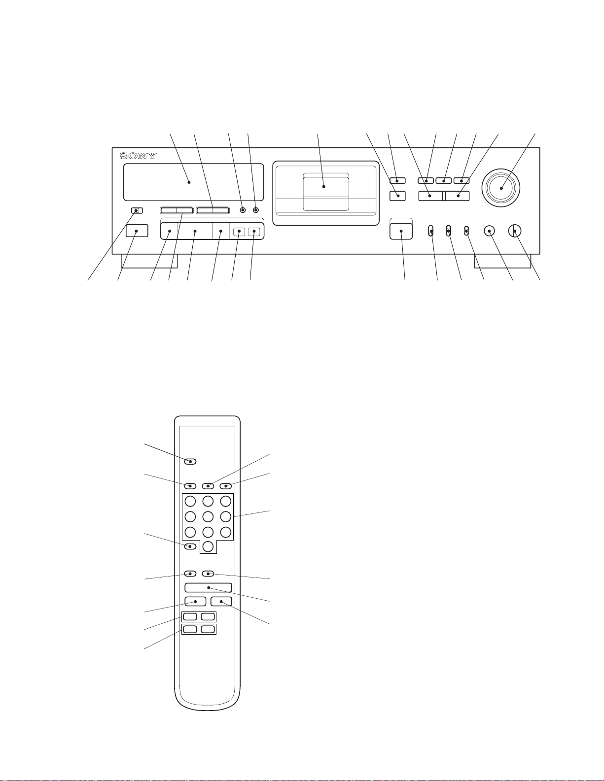
Location of Parts and Controls
27 26 25 24 23 22 21 20 19 18 17 16 15 14
13121110987654321
19
32
31
21
25
24
2
22
23
20
30
29
28
Front panel
SECTION 2
GENERAL
Remote commander (RM-D757)
1 Display window
2 0/) (REW/FF), DATA buttons
3 MODE, MENU button
4 RESET, ENTER button
5 Cassette holder
6 Remote sensor
7 MARGIN RESET button
8 WRITE button
9 START ID AUTO button
10 START ID RENUMBER button
11 START ID REHEARSAL button
12 ERASE button
13 REC LEVEL control
14 PHONE LEVEL control
15 PHONES jack
16 SBM switch
17 REC MODE switch
18 ID MODE switch
19 6 OPEN / CLOSE button
20 r REC button
21 R REC MUTE button
22 P PAUSE button
23 ( PLAY button
24 =/+ AMS, SELECT buttons
25 p STOP button
26 POWER button
27 INPUT switch
28 COUNTER MODE button
29 COUNTER RESET button
30 Numeric buttons
31 CLEAR button
32 REPEAT button
– 5 –

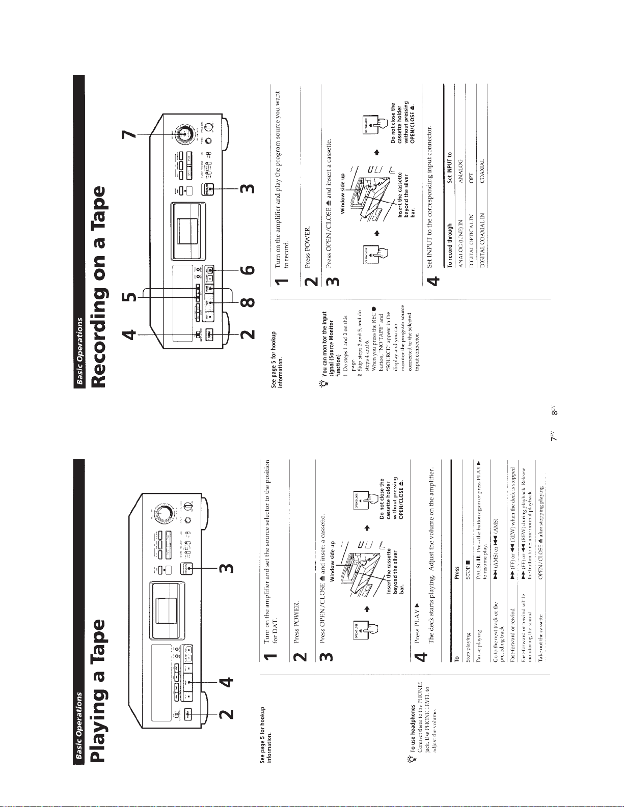
This section is extracted from
instruction manual.
– 6 –
– 7 –

– 8 –
– 9 –

– 10 –
– 11 –

– 12 –

– 13 –
DISASSEMBLY
)
Note: Follow the disassembly procedure in the numerical order given.
SECTION 3
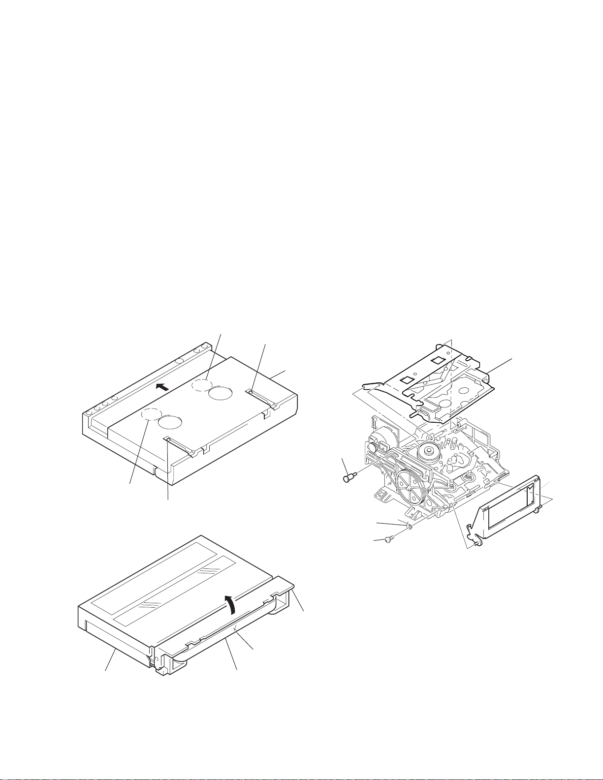
3-1. CASE
Unscrew the four case attachment screws and remove the
case.
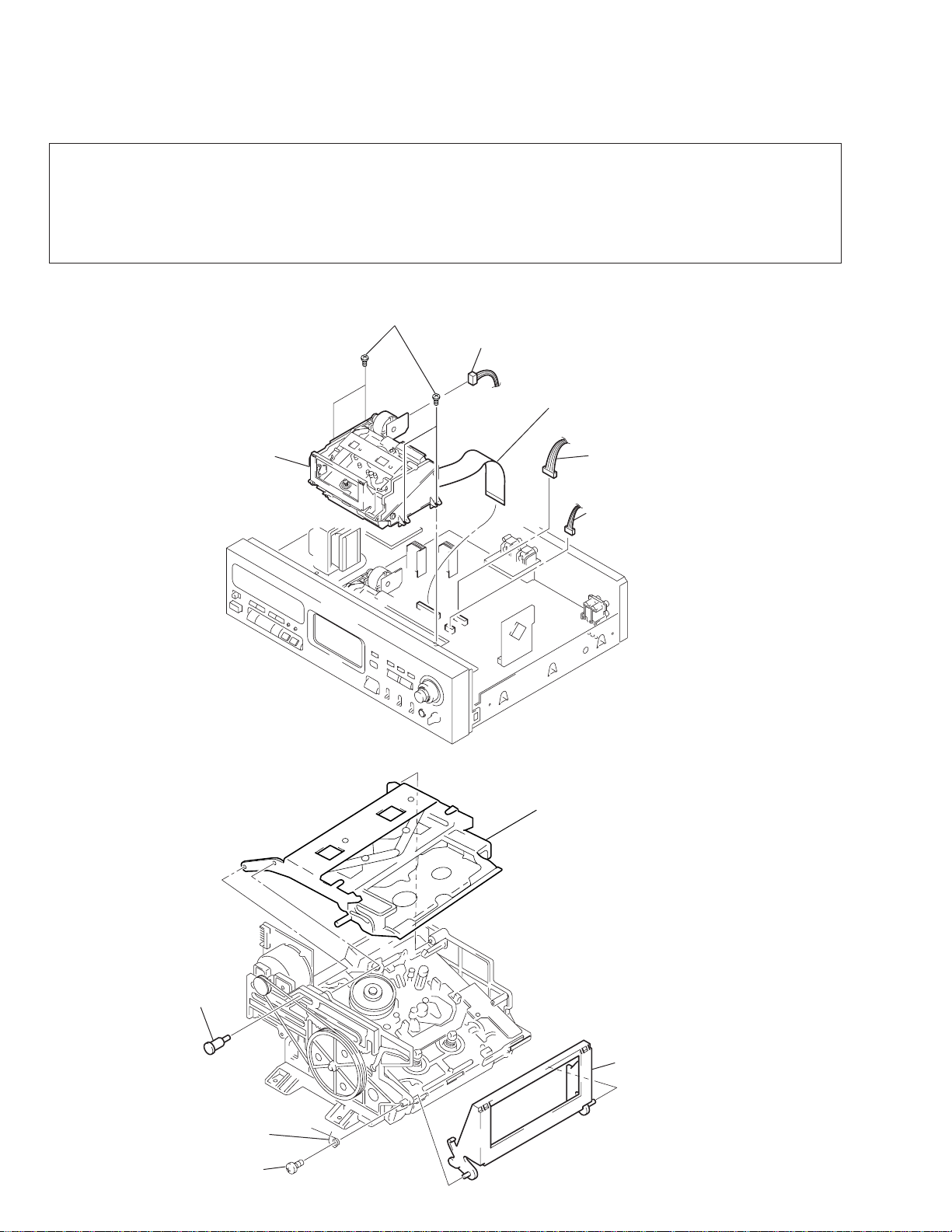
3-3. MECHANISM DECK
6
Mechanism deck
1
Four screws
(PTTWH3x6)
3-2. CASSETTE WINDOW
1 Press the OPEN/CLOSE switch to effect LOADING OUT
STATE (if power is not supplied) rotate the pulley in the
left side of the Mechanism Deck counterclockwise.)
2 Remove the cassette by lifting the window up.
2
Connector (CN1)
3
Connector (CN302)
4
Connector (CN341
5
Connector (CN301)
3-4. CASSETTE HOLDER ASSSEMBLY
1
Screw (Step)
4
Spring (Cassette)
3
Screw
(BVTP3x6)
– 14 –
2
Cassette holder assembly
5
Holder (Window)
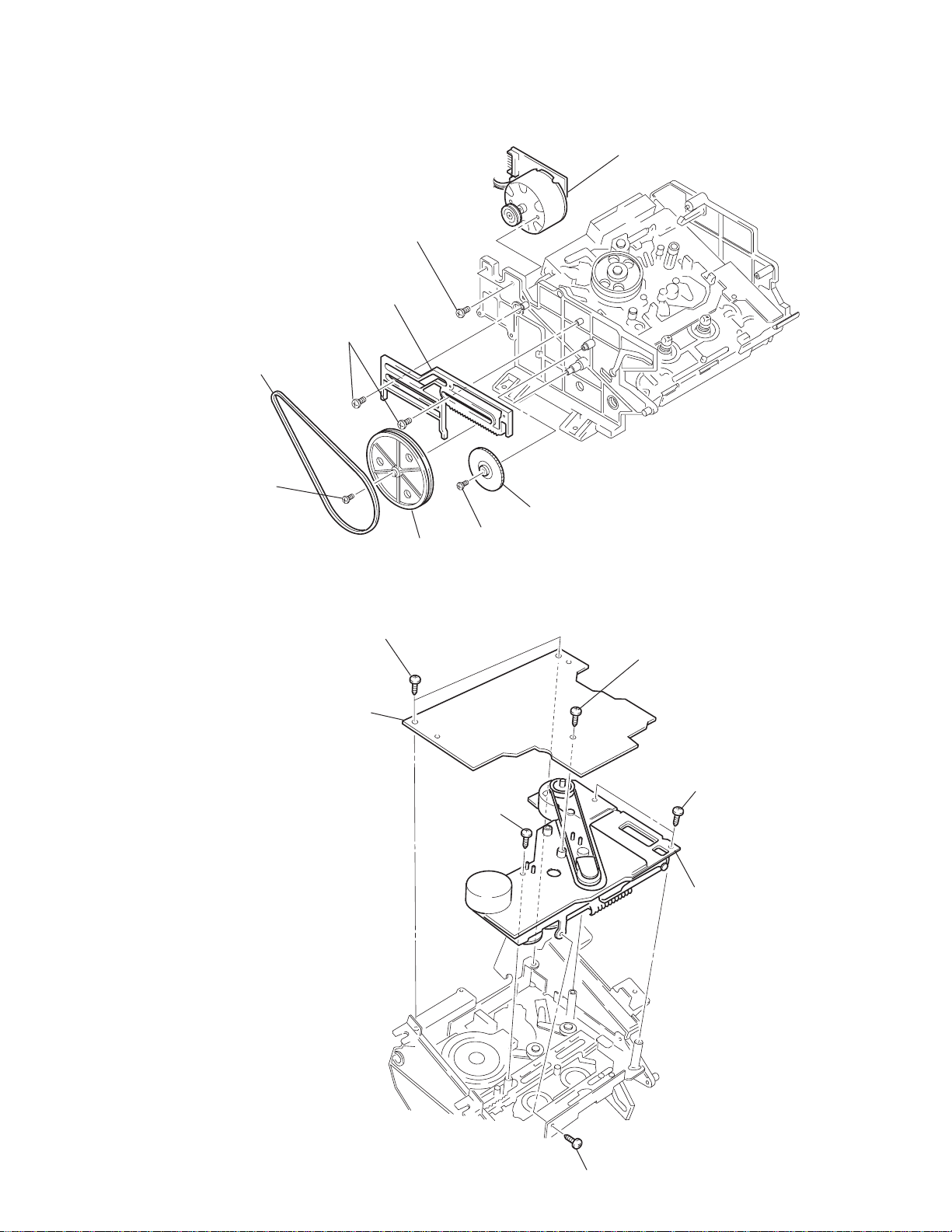
3-5. CASSETTE COMPARTMENT MOTOR (M901), PULLEY, DRIVING GEAR AND SLIDER
s
9
Cassette compartment motor
(M901)
8
Two screws
(P2.6x3)
7
Slider
6
Two screws
(BTP1.7x3)
1
Belt (Driving)
2
Screw
(BTP1.7x3)
5
Driving gear
4
3
Pulley
Screw
(BTP1.7x3)
3-6. DRUM DRIVE BOARD AND DRIVING CHASSIS
3
Remove the lead wires
from connectors on the
drum drive board.
4
Drum drive board
2
Two screw
(B2.6x4)
6
Screw
(BTP2.6x8)
1
Screw
(BTP2.6x6)
5
Two screw
(BTP2.6x8)
8
Driving chassi
– 15 –
7
Screw
(B2.6x4)

3-7. DRUM
y
4
Remove the drum lead
wires from connectors.
5
Drum
2
Four screws
(B2x4)
3
Shield case
1
Lever (Cleaner) assembl
3-8. CAPSTAN MOTOR (M902)
1
Three screws
(P1.7x4)
2
Capstan motor
(M902)
– 16 –
Hub hole
Hub hole
Slider lock
Slider
Slider lock
Lid
Slider
Cut here.
Tape
Step screw
Spring
(cassette)
Screw
(BVTP3x6)
Holder
Holder
(window)
SECTION 4
ADJUSTMENTS
4-1. Notes When Making Adjustments
1. Adjustments should be performed in the order listed.
2. Use the following test tapes:
TY-7111X (8-909-823-00)............................... Level
TY-7252 (8-909-822-00).................................. Tracking
TY-7551 (8-909-814-00).................................. Functions
TY-30B (8-892-358-00) ................................... Blank
Use the following torque meter:
TW-7131 (8-909-708-71) ................................ FWD
3. Switches and controls should be set as follows unless otherwise
specified.
ID MODE switch : START
REC MODE switch : LONG
INPUT switch : OPT
SBM switch : OFF
REC LEVEL control : Min.
PHONE LEVEL control : Min.
4. Creating an end sensor cassette
(1)Press the tape slider lock and move the slider in the direction
indicated by the arrow.
5. Cleaning of the Revolving Drum
(1)Fold a cleaning piece (2-034-697-00) or a knit cloth into 4 or
more files, slightly impregnate it with a head cleaning fluid (9919-573-00), and softly touch the drum with it and manually
rotate the drum slowly counterclockwise by 2 to 3 turns for
cleaning.
(2)At that time, be careful not to move the cleaning piece vertically
to the head tip. Otherwise, the head tip may probably be
damaged.
6. Be careful not to move RV1 to RV2 on the RF AMP board in the
mechanism assemlby
7. To adjust the tape path and guides, remove the holder assembly as
shown in the diagram and use the DAT cassette holder jig (J-8000002-A). This will make it easier to perform the adjustments.
• First turning the pulley counterclockwise to put it in loading out
status will make removal and reattachment of the holder assembly
easier.
• T o perform adjustments, turn the pulley clockwise to put it in loading
in status, load the cassette tape and set the IN switch to the ON
position.
(2)Open the lid and cut the tape.
(3) Turn the hubs until the tape is completely inside the cassette
(both T and S sides).
The end sensor cassette for end sensor adjustments is now ready
for use.
8. Test mode
To set the test mode, short-circuit JW091 (X TEST) and ground
of the main board. (At this time, the dB display of the fluorescent
display level meter will blink.)
Perform the following adjustments in the test mode.
• FWD torque adjustment
• FWD back tension check
• Tape path fine adjustments
• DPG adjustment
• AGC voltage check
• End sensor check
• T o reset the test mode (main), disconnect the wire shorting JW091
(X TEST) and ground. After completion of adjusting, be sure to
reset the test mode (main).
– 17 –

9. Check the following items f or correct tape speed, after completion
of adjusting.
(1)Set the REC MODE switch to 48k and check for normal recording
and playback. (x1)
(2)Set the REC MODE switch to LONG and check for normal
recording and playback. (x0.5)
(3)With QUE (”+)) or REVIEW (”+0), check that qurr r, qurrr
sound is heard. (x3, x8)
(4)Check that correct time is displayed after FF ()) or REV (0).
(x16)
(5)Check that AMS (+, =) is normal.
4-2. ELECTRICAL ADJUSTMENTS
FWD T orque Adjustment
Procedure:
1. Set the test mode (main) and load the FWD torque meter TW7131 (8-909-708-71) .
2. Set the PLAY (() mode.“TORQUE” will be displayed on the
fluorescent indicator tube.
3. Adjust RV451 so that the minimum value of FWD take up torque
(take-up side rewinding torque) is between 9-10g • cm (0.13-0.14
oz • inch).
Also, make sure that the maximum reading does not exceed 15g •
cm (does not exceed 0.21 oz • inch).
4. Confirm that the value indicated by the torque meter is maintained
for one full cycle.
FWD Back Tension Check and Adjustment
Check procedure:
1. Put the set into the test mode (main • servo) and load the FWD
torque meter TW-7131 (8-909-708-71).
2. Put the set into the PLAY (() mode.
3. Turn the FWD back tension adjustment screw locked on the
mechanical deck side so that the minimum value of FWD back
tension torque (supply side) is between 4.5 to 7.5g • cm- (0.06-
0.1 oz • inch).
Also, make sure that the maximum reading does not exceed 8g •
cm (does not exceed 0.11 oz • inch).
After completion of adjusting, be sure to apply screw lock.
4. Confirm that value indicated by the torque meter is maintained
for one full cycle.
5. If the specified values are not satisfied, replace the lever (BT)
assembly (X-3363-024-1).
– 18 –
FWD back tension
adjustment screw
(+P2x2.5)
To tighten (clockwise) - back tension becomes larger.
to loosen (counterclockwise)-back tension becomes smaller.
Tape Path Fine Adjustment (x1.5 FWD Mode)
Perform the following adjustment when the drum has been replaced.
Procedure:
1. Connect an oscilloscope CH-1 to JW183 (PBRF) and CH-2 to
JW092 (SWP) on the main board.
2. Set the test mode (main) and load test tape TY-7252 (8-909-822-
00).
3. Press the AMS (+) key. “DPG” will be displayed on the
fluorescent indicator tube.
Each part of switches on Test Mode.
OFFSET
–0+
ANALOG
OPT COAXIAL
INPUT
REC MODE
STANDARD
48 kHz
44.1 kHz
LONG
OFF
AFT
ON
 Loading...