

Sony PCM-F1 Operating Instructions Manual
OPERATING INSTRUCTIONS
Before operating the unit, please read
this
manual thoroughl
y.
This manu
al
should be retained for future reference.
TABLE
OF
CONTENTS
Owner's record
..................
....
..... ..........
.........................
. 2
Warning
...............
... ... ......
...
....
...
....
.. .
....
.. ....
.....
.....
........
2
Featu res
...............................
." ........................................
2
Pr
eca
utions
......................
......
...
... ......
.............................
3
Power sources
..................
.....
................
...
...
........
...
......
. 4
For o
ut
door
use- using the rechargeable b
attery
pack
......
4
For
Indoor use·- using the ac power adaptor
.....................
5
F
or
use In a
car-us
ing
the
car
batte
ry cord ..
...................
5
System connections
...................
......
...................
....
.........
6
Connection notes
......................................................
6
Connection with the
Sony SL-2000 video cassette
recorder (for outd
oor
live recording)
..............................
6
Connection with a video cassette recorder
other
than
the
SL-2000 ...
..............................
...
........................
7
L
ocation
and fu
nction
of
contro
ls
......................
....
.............
8
Preparation
........................
...
..................................
..... 11
Recording ...
.........
.....
....................................................
12
Recording
level adju
stment
......
....
.............................
13
Record muting
........................
...
..............................
13
Playback
................................................
.. ...
................
14
Adjusti ng the tracking of the video cassette reco rder ..
.......
14
How
to
use the MUTING switch
...
......
....
......
.................
14
Di
gital
tape copy .
.'
................
............................
....
......
....
15
Time
r-
activated recording ......
...
......
.... ........
...
.....
....
....
.....
16
More about system
connec
tions
.......................................
18
System connec
tions fo
r recording using
thr
ee
or
more
microphones
...................
.. :
.....
...
...........................
18
Connection
with
the Sony SL-2000 video cassette
recorder
for
indoor
use
..................
...
.........
...
......
...
19
Connection wi th the Sony SL-2000 recorder and
the
Sony TT-2000
tuner
timer
unit
..............................
20
Using one video cassette recorder
for
PCM
recording and
playback and
for
record ing and playing back TV
programs
.......................
....
.................................
21
Attaching
the shoulder strap ..
....
.. ...... ..
.............................
22
Spec
ifi
cat
ions
.........................
.......
...
..... ...
.....
....
.......
...
23
Technical
information
...........................
...... ...
...
....
..........
. 24
Basic termi
nology
...................................................
24
System and circuit
description
......
.... ..........................
25
Bl
ock
diagram
..................
.....
....
... .. .
.....
.........................
27
© 1982 by Sony Corpora
ti
on
OWNER'S RECORD
The model and serial n
umb
ers are
loca
ted on
the
bottom.
Record
the
serial
number
in
the
space provided below. Refer
to
these
numbers whenever you
ca
ll upon your Sony dealer regarding
this
product.
Model No. PCM·F1
Serial
No.
---
-
~~
-
WARNING
To prevent fire
or
shock
hazard,
do
not
ex-
pose
the
unit
to
rain
or
moisture.
This
equipment generates and uses radio
frequency energy and
if
not
installed
and
used
properly,
that
is, in
strict
accordance
with
the
manufacturer's
instructions,
may
cause interference
to
radio and telev ision
reception. It has been type
tested
and found
to
comply
with
the limits
for
a Class B com-
puting
device in accordance
with
the
specifi-
cations
in Subpart J
of
Part 15
of
FCC Rules,
which
are designed
to
provide reasonable
protection
against
such interference in a
residential
installation
. However, there is no
guarantee
that
interference will
not
occur
in
a
particular insta
llation. If
this
equipment
does cause interference
to
radio
or
televi-
sion reception,
which
can be determined by
turning
the
equipment
off
and on,
the
user is
encouraged
to
try
to
correct
the
interference
by
one or more
of
the
following
measures:
-reorient
the
receiving
antenna
-re
locate
this
equipment
with
respect
to
the receiver
-move
this
equipment away from
the
re-
ceiver
-plug
this
equipment
into a different
outlet
so
that
equipment
and receiver are on dif-
ferent branch
circuits.
If necessary,
the
user
should
consult
the
dealer
or
an experienced radio/television
technician
for
additional
suggestions. The
user
may
find
the
following
booklet prepared
by
the
Federal
Communications
Commis-
sion helpful:
2
"How
to
Ide
ntify
and Resolve Radio-TV In-
terference Problems".
This
book
let is available from
the
U.S.
Government Printing Office, Washington,
DC
20402,
Stock
No. 004-000-00345
-4.
To avoid
electrica
l shock,
do
not open
the
cabinet. Refer servicing
to
qualified
person-
nel only.
FEATURES
In conventional analog recording systems,
the
qual i
ty
of
sound
reproduction depe n
ds upon
the
properties
of
magnetic
tape and
heads, so
th
at it is virtually
impossib
le to bypass
the
inheren t
limitations
of
conve
nti
ona
l analog recording,
including its
limited
dynamic
range and frequency re
sponse
, and
its
associated
distor-
tion
.
The Pulse Code Modu lation
(PC
M)
system
points
the
way
to
a new
era
in sound repr
oduct
ion. It can
offer
performance and fide li
ty
far
superior
to
any
analog
system.
In the PCM system,
sound
levels are converted
to
a series
of
binary
codes. This
informat
ion is recorded as
digi
tal pulses
of
equal
amplitude
. In playback, all
that
has
to
be done is
to
disc
rim
inate
between
the
presence and absence
of
a pulse. The quali
ty
of
recording and
playbac
k is
thus
not dependent
on
the
charac
teris-
tics
of tape and heads.
The PCM-F1 is
the
newest
addition
to
Sony's line
of
PCM
digital
audio
processors for
consumer
appl i
cations. With
the PCM
-F1
, hi-fi
sound
reproduct i
on with
wide
dynamic
range, minimal
distortion
,
low
wow
and f
lutt
er (lower than the measurable limit
),
and flat fre -
quency
response is achieved. Listening to
the
reproduction
of
your
PCM-F1 is
just
like being in
the
concert hal
l.
Compact,
lightweight
PCM
digital
audio
processor
In conventional di
gital
audio processors, several hundreds
of
ICs
are employed in
digital
processing circuitry, w
hich
makes it dif-
f
icult
to
make
the
unit
compact
and ligh twe
ight.
The three new LSis
for
digital
processing deve loped especial ly
for
digital
audio
processor
use have
successfu
lly made the PCM-F1
compact
and lightweight.
The A/D (analog-to-digital) and D/A
(digital-to-analog) converters, which are newly developed monolithic
ICs, are especia lly
adaptable
to
mass production. This results
in
the
production
of
a PCM
digital
audio processor
that
is more af-
fordable
to
a grea ter proportion
of
aud io-philes.
Resolution
selector
for
recording
and
playback
with
wider
dynamic
range and
less
distortion
The PCM-
F1
was developed in accordance with the technica l spec-
ifications
of
the
Electron ic Industries Assoc iation
of
Japan (EIAJ),
which has adopted
the
14-bit linear
quantization
format. In addi-
tion,
the
unit
has
the
capability
of
recording and playing back in ac-
cordance
with
the
16-bit l
inear
quan
tiz
ation format with wider
dynamic
range and less
distortion
than
the
14-
bit
format. The 14-bit
and 16-bit
formats
can
be selected wi
th
the
RES
(resolution) selec-
tor
.
Three different power sources
The unit can be operated on three
different
power sources: house
current using
the
supplied ac power adaptor,
optional
rechargeable
battery
pack, and 12 V
car
battery
using an
optional
car
battery
cord. When
this
compact,
lightweight
PCM-F1 is combined
with
the
Sony SL-2000
por
table
video cassette recorder,
you
can make a live
field recording
with
wide
dynamic
range, min imal di
sto
rtion, and
flat frequency response.
Stab
le power supply
Two de-to-de converters in
corpora
ted in
the
unit-one (±5
V)
for
th e
di
gital circuitry
and
the
other (±15
V)
for the
analog
circuitry-
assure
stab
le power suppl
y.
Easy tracking adjustment
of
video heads
Correct
track
ing
adjustment
of
the
video hea
ds
can be easily per-
formed by observing a meter.
Muti
ng
switch for continuous sound reproduction
Wi
th t he MUTING
switch
set
to
OFF,
the
reproduced sound is
not
cut
off
even
if
many
dropouts
occur,
or
if
the
tap
_e is
not
being
transported
at
the
proper
playback
speed.
Reco
rd
muting function a
llows
you
to
easily inse rt a blank space
between sel
ections
.
Multi-generati
on
digital-to-digital tape copy can be performed
with
absolu tely
no
deteri
oration in signal
qual
ity.
With the highly perfected error detection and correction circuits
in-
corporated,
the
reproduced sound
quali
ty
is
not
affected
by
dropout
errors.
You can choose either of two ways to have the peak level indicated
on the LED peak p
rogram
meters.
Microphone head
am
plifiers are incorporated f
or
recording
directly
from microphones and provide excellent
sound
qualit
y.
PRECAUTIONS
On safety
• Operate t
he
unit
only
on 12 V de.
For
ac operation, use
only
the ac
power
adaptor
supplied
with
the
unit.
Do
not
use any
other
ac power
adaptor
. Operate
the
supplied
ac power
ada
ptor
only
on
120 V ac,
60
Hz.
For
car
battery
operation, use
only
the
car
battery
cord recom-
mended
for
this
uni
t.
Do
not
use any
other
car
battery
cord.
• Sh
ould
any
liquid
or
solid
object
fal l
into
the
cabinet
of the
unit
or
the
ac power adaptor, unplug the
units
and have them checked
by
qualified per
sonne l
before
operating
them
any
further.
•
Unplug
the
ac power adaptor from
the
wall
outlet
if it
is not
to
be
used
for
an extended period
of
time. To di
sconnect
the
cord, pull
it
out
by grasping the plug. Never pull the cord
itself
.
On inst allation
•
Do
not
ins
tall
the unit and
the
ac power
adaptor
in a
location
near
heat
sources such as radiators
or
air
ducts, or in a place subject
to
direct
sunlight,
excessive dust, mechanical
vibration
or shock.
• Good air cir
culation
is essential
to
prevent internal heat build-up
in
the
unit
and
the
ac power adaptor. Place these
units
in a location
with
adequate
air
circu
lation. Do
not
place
the
ac power
adaptor
on
a
soft
surface,
such
as a rug,
tha
t would
block
the
ventilation
slots
on
the
bottom.
• Do not place
anything
on top
of
the
cabinets. The
top
ventilation
slots
of
the
ac
power
adaptor
must
be u
nobstructed
for
proper
operation
of
the
unit
and
to
prol
ong
the
life
of its
components.
On operati
on
• Before
making connections,
be sure
to
turn
off
each component.
• The mut ing
circuitry
of
the
unit may activate
if
a vacuum cleaner,
electric
shaver, transceiver
or
similar device
causes interference.
• When
the
unit is not being used,
turn
the power
off
to
conserve
energy and
to
extend
the
life of your unit.
On cleaning
Clean the cabinet, panel and
controls
with a soft cloth lightly
moistened
with
mild dete rgent so
lut
ion. Do not use any type
of
abrasive pad, scouring powder or solvent such as al
cohol
or ben-
zine.
On repacking
Do
not throw away
the
car
ton
and
the
packing
material.
It makes an
ideal
container
to
transport
the unit. When shipping
the
unit
for
repair
work
or
to
another
location, repack it as ill
ustrated
on
the
carton
box.
For the customers in the USA
For detailed
safety
precau
tions
, see
the
leaflet " IMPORTANT
SAFEGUARDS
".
If you have any
questions
or probl
ems
concerning
your
unit
, please
contact
your
nearest Sony dea ler.
3
POWER SOURCES
The unit can be operated on any one
of
the
following
power sources:
-AC
power supply using
the
AC-700 ac power
adaptor
(supplied)
-So
ny
NP-1
rechargeable
battery
pack
(optional)
-12 V car
battery
using the Sony DCC-2400B car
battery
cord (optional)
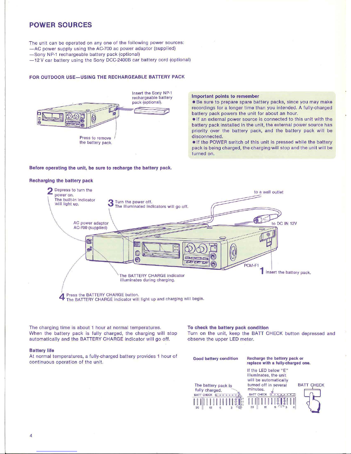
FOR OUTDOOR
USE-USING
THE RECHARGEABLE BATTERY PACK
Press
to
remove
the battery pack.
Insert
the
Sony
NP-1
rechargeable battery
pack
(optional
).
e
-o
Before
operating
the
unit,
be sure
to
recharge
the
battery
pack.
Recharging
the
battery
pack
2 Depress to turn the
power on.
Important
points
to
remember
• Be sure
to
prepare spare
battery
pac ks, since you
may
make
recordings f
or
a lo
nger
time than you
inte
nded. A
fully-cha
rged
battery
pack powers the u
nit
for
about
an
hour
.
• If an external
power source
is
connected
to
this unit with the
battery
pack
insta
lled in
the
unit,
the
external power
source
has
prior i
ty
over
the
battery
pack, and
the
battery
pack
will be
disc
onnec ted.
e lf
the
POWER swi
tch
of this unit is pressed while
the
battery
pack is being charged, the charg ing•will
stop
and
the
un it will be
turned on.
to a wa
ll ou t let
The built-in
indicator
will
light
up.
J Turn the power o
ff
.
The
illum
inated
indicato
rs
will
go
off
.
The
BATIERY
CHARGE
Indicator
illuminates
during
charging.
Insert the battery pack
.
4
Press
the
BATIERY CHARGE
button.
The BATIERY CHARGE
indicator
will light
up and charging
will
begin.
The charging
time
is
about 1 hour
at
normal temperatures.
When
the
battery
pack is fully charged,
the
charging
will
stop
automat
ica
lly and
the
BATTERY CHARGE
indicator
will go
off.
Battery life
At normal temperatures, a
fully
-charged
battery
provides 1
hour
of
continuous
operat i
on
of
the
unit.
4
To
check
the
battery
pack
condition
Turn on
the
unit, keep
the
BATT CHECK bu
tto
n depressed and
observe
the
upper LED meter.
Good
battery
condition
Recharge the battery
pack
or
replace
with
a fully-charged
one
.
If t
he
LED bel
ow "E"
il
lumin ates,
the unit
w
ill
be
automatically
The battery pack
is
turned
off
in several
BAIT
CHECK
fully charged.
minutes
. eel
BATT
CHECK
BA
TT
~CH:iEE~CK<_j
~~~
~
~~~.~~q~~~3~
~~~
~~~,t
H~~'j3
~q
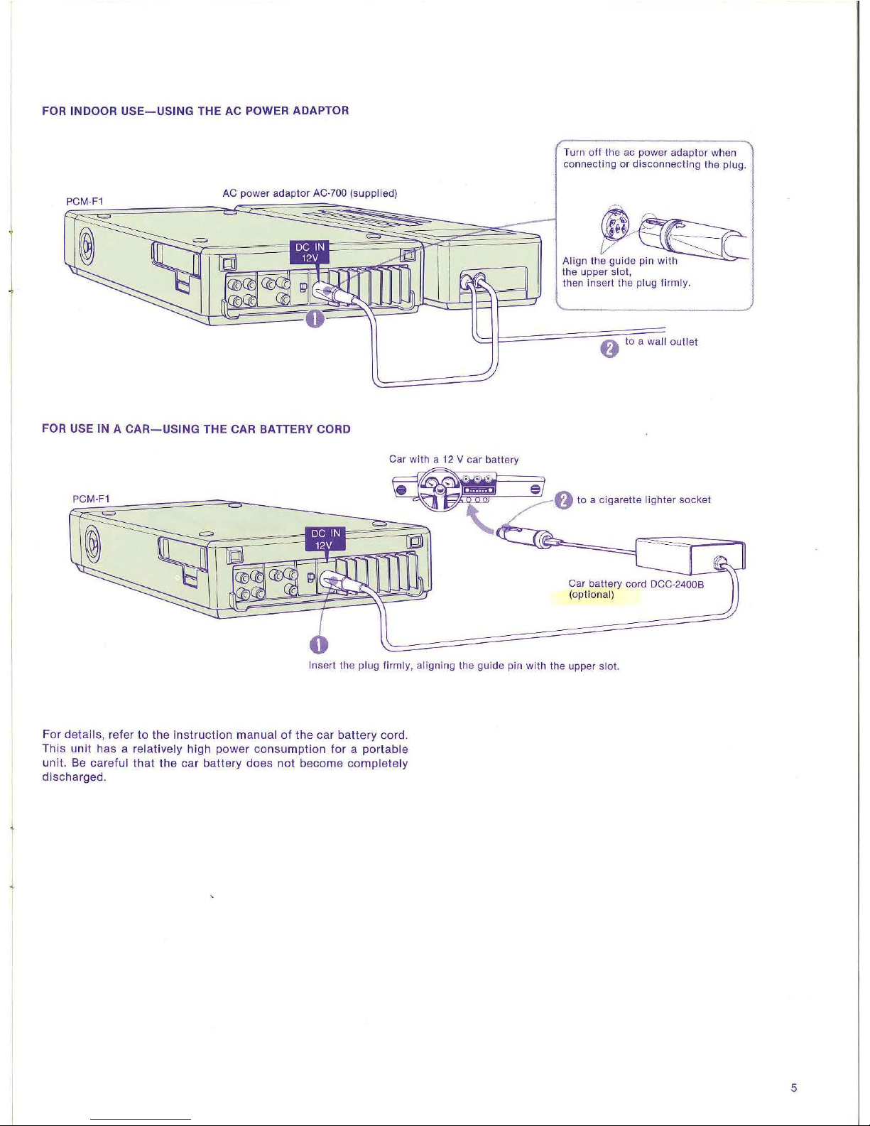
FOR INDOOR
USE-USING
THE
AC
POWER ADAPTOR
AC power ada
pto
r AC-700 (supplied)
FOR
USE
IN A
CAR-USING
THE CAR BATTERY CORD
Turn
off the
ac
power
adaptor
when
connecting
or
disconnecting
the
plug.
~~
Align
the
guide pin
with
t
he
upper
slo
t,
then insert
the plug fir
mly
.
f}
to a
wall
outle
t
to a cigarette ligh t
er
soc
ket
In
sert
the
plug f
irmly, aligning
the
guide
pin
with
the
upper slot.
For details, refer
to
the
instruction
manual
of
the
car
battery
cord.
This
unit
has
a relatively high
power
consumption
for a portable
unit.
Be c
areful
that
the
car
battery
does
not
become
completely
discharged
.
5
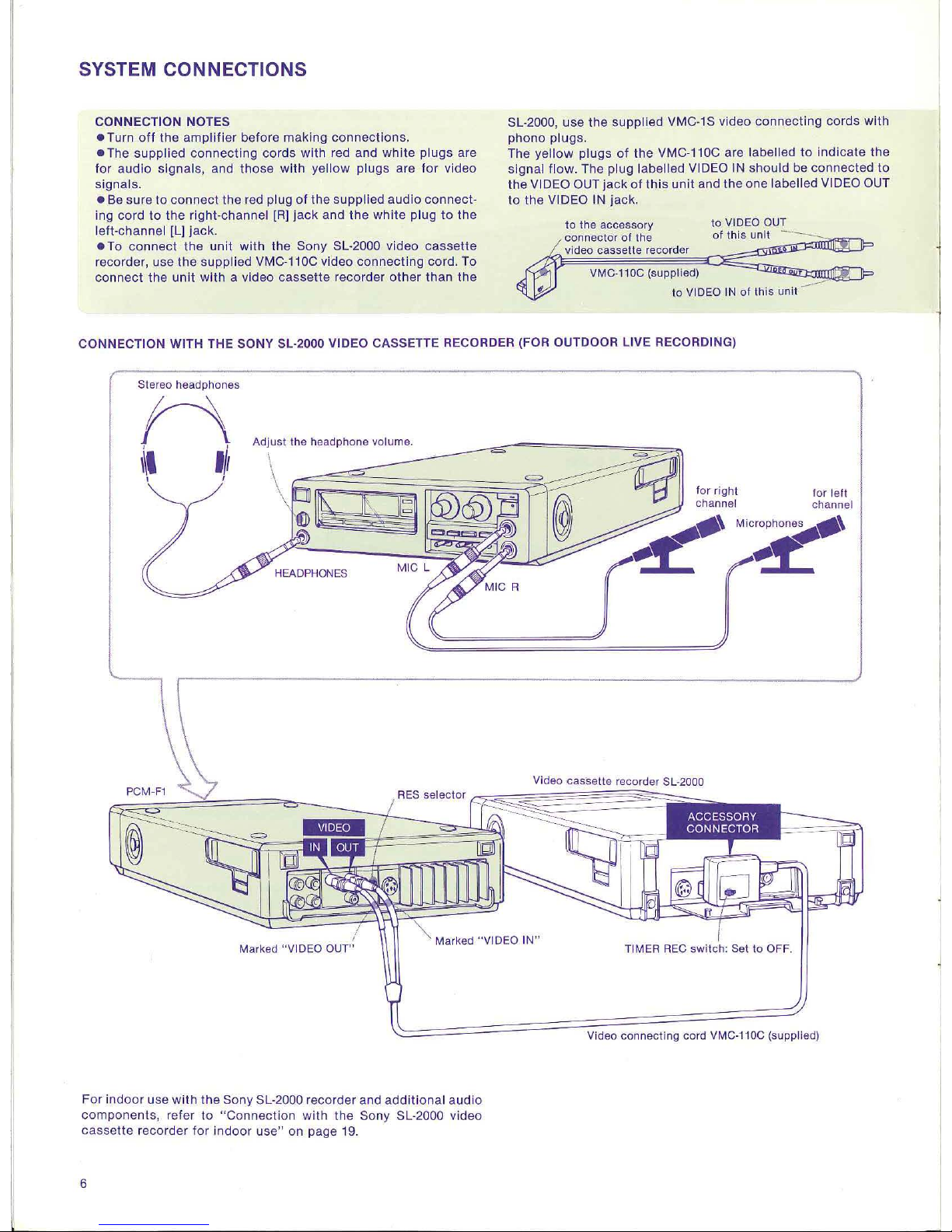
SYSTEM CONNECTIONS
CONNECTION NOTES
• Turn
off
the amplifier
bef
ore making
connect
ions.
• The supplied co nnecting cords w ith red and wh
ite
plugs
are
for audio si
gnals,
and t hose with yell
ow
plugs are
for
video
signa ls.
• Be sure
to con
nect
the red pl
ug
of the suppl ied audio connect-
in g cord
to
the ri
ght-cha
nnel [R] j
ack
and the whi
te
plug
to
the
l
eft
-channel [L]
jac
k.
• To conn
ect
the
uni t with the Sony SL-2000 video cassette
recorder, use
the
supplied VMC-110C video conn
ect
ing cord. To
connect
the
unit with a video cassette reco rder other
than
the
SL-2000, use
the
supplied VMC-1S video connecting cords with
phono plugs.
The
yellow
plugs of the VMC-11
0C
are labelled
to
in dicate
the
si
gna
l flow. The plug labe ll ed VI
DEO
IN should be connected
to
the VIDEO OUT jac k of this unit and the one labelled VI
DEO OUT
to the VIDEO IN
jack
.
to
the
accessory to VID
EO OUT
connecto
r of the of this unit -
vid
eo
cassett
e recorder
VMC-110C (
supp
lie
d)
to
VIDEO IN of th
is unit
CONNECTION WITH THE SONY SL-2000 VIDEO CASSETTE RECORDER (FOR OUTDOOR LIVE RECORDING)
Stereo headphones
n
\\t
,,,
1 I
A
djus
t t
he
hea
dpho
ne v
olu
me.
\
~~~~~
~
Marked "VIDEO I
N"
For indoor use with
the
Sony SL-2000 recorder and additional audio
components, refer to
"Connection with
the
Sony SL-2000 video
cassette recorder for indoor
use"
on page 19.
6
f
or
right
channel
for
left
channel
Video conne
ct
ing cord VMC
-110
C (supplied)
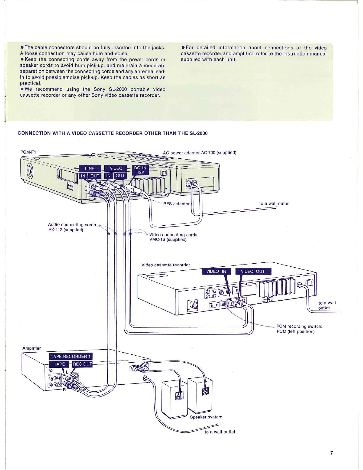
• The cable connectors should be fully inserted
into
the
jacks
.
A
loose connection may cause hum and noise.
• Keep the connecting cords away from the power cords
or
speaker
cords
to
avoid hum
pick
-up, and maintain a moderate
separation between the connecting cords and any
ante
nna lead-
in
to
avoid
possib
le 'noise
pick
-up. Keep the cables as short as
practical.
•
For detailed infor
matio
n about
connections
of
the video
cassette recorder and amplifier, refer
to
the
instruction
manual
supplied
with
each unit.
• We recommend using the Sony SL-2000 portable video
cassette recorder
or
any other Sony video cassette recorder.
CONNECTION WITH A VIDEO CASSETTE RECORDER OTHER THAN THE SL-2000
Audio connecting cords
RK-112 (supplied)
Video
connecting
cords
VMC-18 (supplied)
Video cassette recorder
to a
wall
outlet
to
a wa ll
outlet
PCM
recordi
ng
switch:
PCM (left position)
Amplifier
TAPE RECORDER 1
7
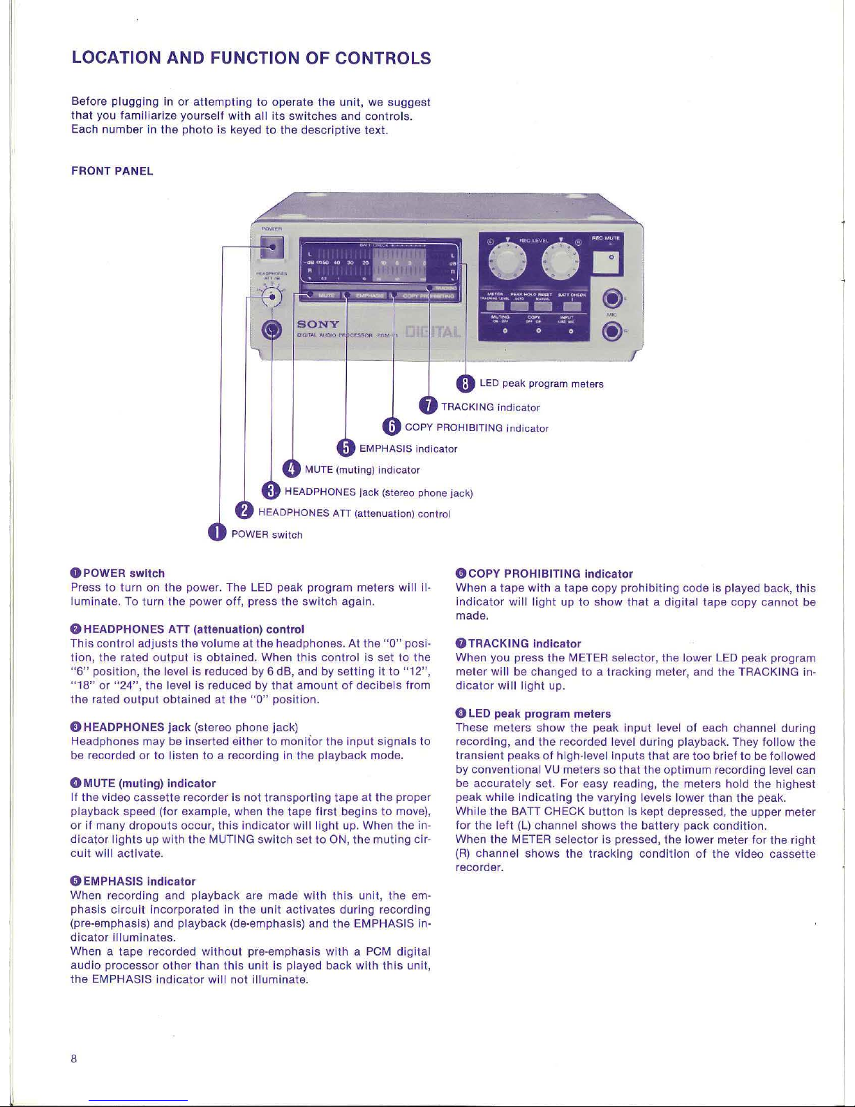
LOCATION AND FUNCTION OF CONTRO LS
Before plugging in
or
attempt
ing
to
opera
te
the unit
, we sug g
est
that
you fami
lia
rize yourself wi
th
all
its
switc
hes and
cont
rols.
Each
number
in
the
photo
is keyed
to
the
descriptive
text.
FRONT PANEL
LED
peak
program
meters
COPY PROHI
BIT
ING
ind
icator
EMPHAS
IS indicat
or
0 POWER switch
MUTE (muting)
indicator
HEADPHONES
ATI
(attenuation)
con
trol
POWER
switch
Press
to
turn on
the
power. The L
ED
peak program meters will il-
luminate.
To
turn
the
power
off,
press
the
switch
again.
f)
HEADPHONES ATT (attenuation) control
This
control
adjusts
the
volume
at
the headphones.
At
the
"0"
posi-
tion,
the
rated
output
is
obtained.
When
this
control
is set
to
the
"6" position,
the
level is reduced
by
6 dB, and by
sett
ing
it
to "12",
"18"
or
"24",
the
level
is
reduced by
that
amount
of
decibe
ls from
the
rated
output obtained at t
he
"0"
position.
0 HEADPHONES jack (stereo phone jack)
Headphones
may
be inserted either
to
monitor
the input
signals
to
be recorded
or
to
listen
to
a recording in t
he
playback
mode.
0 MUTE
(m
uti
ng)
indicator
If the video
cassette
recorder is not
tra
nspor
ting
tape at
the
proper
playback
speed (for example, when
the
tape
first
begins
to
move),
or
if
many
dropouts
occur,
this indicator
will light
up. When
the
in-
dicator lights
up
with
the
MUTING
switch
set
to ON,
the
muting cir-
cu
it
will activate.
0 EMPHASIS indicator
When recording and
playback
are made
with
this
unit,
the
em-
phasis
circuit
incorporated in
the
unit
act
ivates
during
recording
(pre-emphasis) and
playback
(de-emphasis) and
the
EMPHASIS in-
dicator
illuminates.
When a tape recorded
without
pre-emphasis with a PCM dig
ital
audio
processor
other
than this unit is played
back
with this uni t,
the
EMPHASIS
indicator
will
not illum
inate
.
8
()COPY
PROHIBITING indicator
When a
tape
wit
h a tape
copy
prohibi
ting
code is played bac
k,
this
ind
icator
wi ll lig
ht
up
to
show
that a
digita
l tape
copy
cannot
be
made.
8TRACKING
indicator
When you press
the
METER selector,
the
lower LED peak pr
ogram
meter
wil l be changed
to a tracking
meter, and
the
TRACKI
NG
in-
dicator
wi II light up.
0
LED peak program mete
rs
These
meters
show the
peak in
put
level of each channel during
recording, and
the
recorded level during playback. They fol
low
the
transient
peaks of high-level
inp
uts
that
are too
brief
to
be followed
by
conventional VU meters so
that
the optimum record
ing
level can
be
accurately
set. For easy reading,
the
meters hold the
highest
peak
whi
le
ind
icating
the
vary ing levels lower th an
the
peak.
While
the
BATT CHECK
button
is kept depressed, the upper meter
for
the
left
(L)
channel
shows
the
battery
pack
condition.
When
the
METER
selecto
r is pressed, the
lower
meter for the
right
(R)
channel
shows
the
tracking
condit
ion
of the video
cassette
recorder.
~
:•=oo
•o
••
:.
~
~I
.....
...
..
__
,
~~....__
I
SONY
0
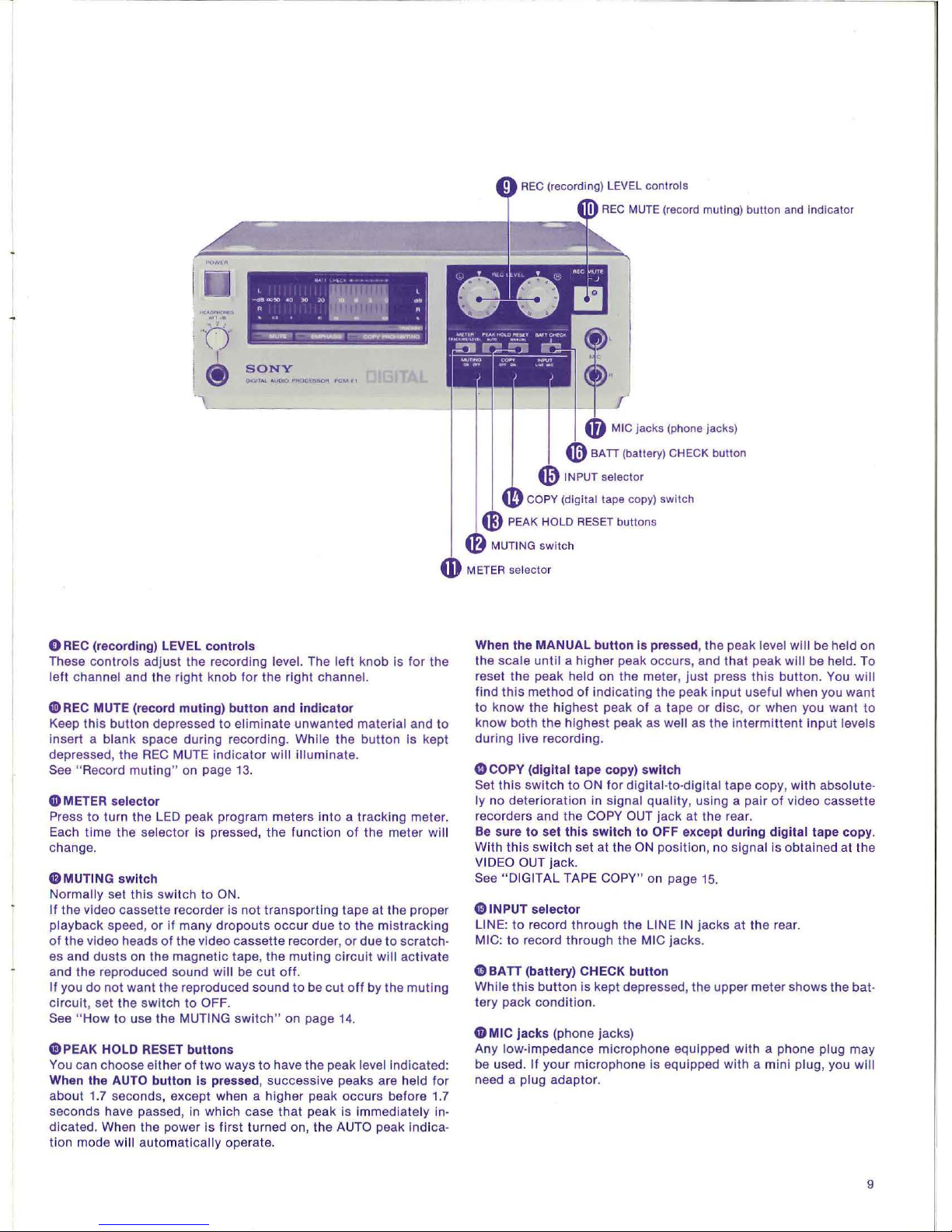
RE
C (recording) LEVEL
contro
ls
These
cont
rols adjust the reco rd ing level. The l
eft
knob is
for
the
left
channel and the
right
knob for
the right
channel.
0
REC
MUTE (record
muting) butt
on
and
indicator
Keep this button depressed
to
eliminate
unwanted material and
to
insert a bl
ank
space during recording. While
the
button
Is kept
depressed, the
REC
MUTE i
ndicator
wil l illuminate.
See "Record
muting"
on
page
13.
CD
METER selector
Pr
ess
to
turn
the LED
peak program meters
into a track
ing meter.
Each
time
the se l
ector
is pressed, the fun c
tion
of
the meter will
chang
e.
$M
UTING
switch
Normally set this
switch
to
ON.
If
the video cassette recorder is
not
transport
ing tape at
the
proper
playback speed,
or
if
many
dropouts
occ
ur
due
to
the mistrack
ing
of
the video heads
of
the video cassette recorder,
or
due
to
scratc
h·
es and
dusts
on the
magnetic
tape, the muting
circuit
will
activate
and the reproduced sound
will
be
cut
off.
If you
do
not
want
the reproduced sound
to
be
cut
off
by the m
uti
ng
circuit,
set
the switch to OFF.
See
"How
to
use the MUTING switch"
on
page 14.
0 PEAK HOLD RESET
buttons
You can choose eith
er of two ways
to
have the peak level indicated:
When the AUTO
butto
n is pressed , successive peaks are held for
about
1.
7 seconds, exce
pt
when a
high
er peak
occurs
before 1.7
seconds have passed, in which case that peak
is
immediately in·
dicated . When the power is first turned on, the AUTO peak indi ca·
lion
mode will automatica
lly
operate.
REC
MUTE (record muting) button and Indicator
When the MANUAL
button
is pressed, the peak level wi ll be held
on
the
scale
until a hi
gher
peak occurs, and
that
peak
will
be held. To
reset the peak held on
th
e meter,
just
press this button. You
will
find this method
of indicating the peak
input
useful when you
want
to
know the
highest
peak
of
a tape
or
disc, or
when you
want
to
know
both the
highest
peak as well as
the
intermi
ttent
input levels
during live record
in
g.
G)
COPY
(digital tape
copy)
switch
Set this
switch to
ON for digital-to-di
gital
tape
copy, with absolute·
ly
no
deterioration in
signal
quality, us
in g a pair
of
video cassette
recorders and the COPY O
UT
jack
at the rear.
Be sure
to
set this
switch
to
OFF except
during
digital tape
copy
.
With
this switch set
at
the ON position, no signal is
obta
ined at the
VIDEO OUT jack.
See "DIGITAL TAPE COPY" on page 15.
G)
INPUT sel
ector
LINE:
to
record thr
ough
the LINE IN
jacks
at
the rear.
MIC:
to record through
the
MIC jacks.
0BATT
(battery) CHECK
button
While this
button
is kept depressed, the upper meter
shows
the bat·
tery
pack
condit
ion.
CDM
IC
jacks
(phone jacks)
Any low-impedance
mi
crophone equ ipped with a phone plug
may
be used . If
your
microphone Is eq
uip
ped
with a mini
plug , you will
need a plug
adaptor
.
9
 Loading...