

Sony PCM-601ESD Operating Instructions Manual
SONY.
DIGITAL AUDIO PROCESSOR
PCM-601ESD
OPERATING INSTRUCTIONS
Page 4
Before operating the unit, please read thi s manual
thoroughly
and ratain
it
for future reference.
MODE D'EMPLOI
Page
20
Avant Ia mise
en
service de
cet
appareil, priere
de
lire
attentivement
ce
mode d'emploi que l'on conservera
pour toute reference ulterieure.
BEDIENUNGSANLEITUNG
Lesen Sie vor der lnbetriebnahme diese
Bedienungsanleitung
sorgfaltig durch, und bewahren Sie
sie zum spateren
~achschlagen
gut auf.
© 1
986
by
Sony Corport
Seite 36
For the customers
in
the United States
OWNER'S RECORD
The model and serial numbers are located at the rear.
Record
the
serial number in the space provided below.
Refer
to
these numbers whenever you call upon your
Sony dealer regarding this product.
Model No.
PCM-601ESD Serial No
..
___
__
_ _
WARNING
To prevent fire or shock hazard,
do
not
expose the unit to rain or moisture.
CAUTION : TO REDUCE THE RISK OF ELECTRIC
SHOCK
,
DO NOT REMOVE COVER (OR
BACK).
NO USER·SERVICEABLE PARTS INSIDE .
REFER SERVICING TO QUALIFIED SERVICE PERSONNEL.
This symbol
is
intended
to
alert the
user
to
the presence
of
uninsulated
"da
ngerous voltage"
within
the prod·
uct's
enclosure
that
may be
of
suffi·
cient
magnitude
to
const
itute
a risk
of
electric
shock
to
persons.
This symbol is intended
to
alert the
user
to
the presence
of
import
ant
operating and maintenance (servicing)
instructi
ons in the
lit
erature accompa-
nying the appliance.
INFORMATION
This equ
ipm
ent generates and uses radio frequency
energy and
if
not
installed
and used properl
y,
that
is, in
strict
accordance
with
the manufacturer's instructions,
ma
y cause interference
to
radio and television recep-
tion. It has been type tested and found
to
comply with
the
limits for
a Class
B computing device in accordance
with the specifications
in
Subpart J
of
Part 15
of
FCC
Rules,
which
are designed
to
provide reasonab le protec-
tion
again
st
such interference in a residential installa·
tion. However, there is no guarantee
that
interference
wi ll not occur in a particular installation. If this equip·
ment does cause interference
to
rad
io
or
television
reception, which
can
be
determined by turning the
equipment
off
and on, the user is encouraged
to
try
to
correct the interference by one
or
more
of
the following
measures:
Reorient the receiving antenna
Relocate the equipment
with
respect
to
the receiver
Move the equipment away
from
the receiver
Plug the equipment
into
a different outlet so
that
equipment and receiver are on different branch cir·
cuits.
If necessary, the user should
consult
the dealer
or
an ex-
perienced radio/television technician for
additiona
l sug-
gestions. The user may
find
the
follow
ing booklet
prepared by the Federal
Communications
Commission
helpful:
"How
to
Ident
ify
and Resolve Radio-TV Interference Problems".
This booklet
is
available from the
U.S.
Government Prin·
ting
Office,
Washington,
DC
20402,
Stock
No.
004-000-00345·4.
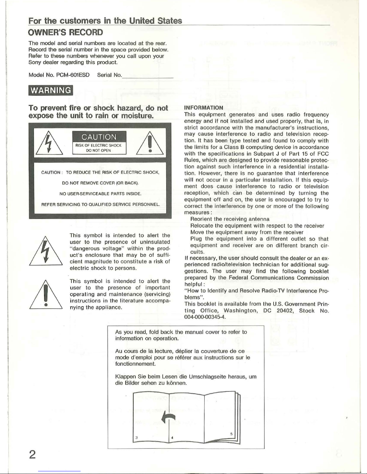
As you read, fold
back
the manual cover
to
refer to
information on operation.
2
Au cours
de
Ia lecture, deplier Ia couverture
de
ce
mode d'emploi pour se referer aux instructions sur le
fonctionnement.
Klappen Sie beim Lesen die Umschlagseite heraus, urn
die Bilder sehen zu konnen.
-
5
3 4
-
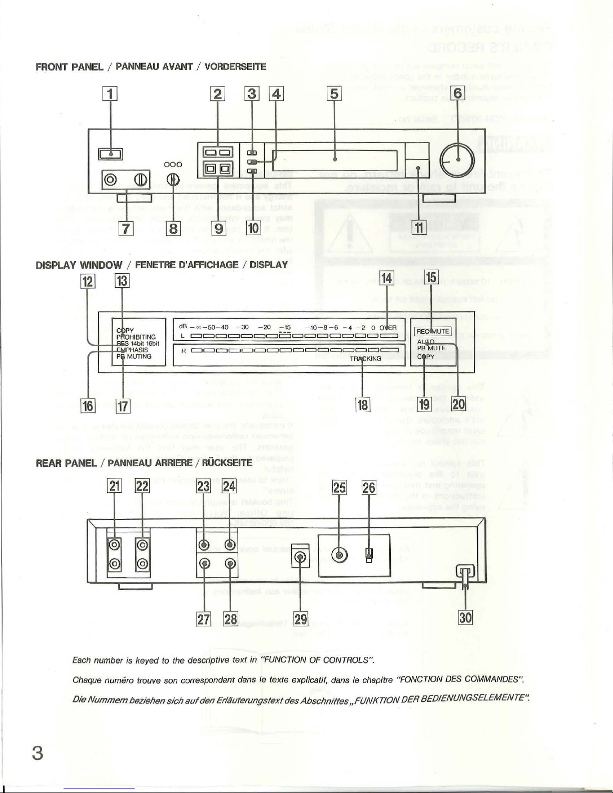
FRONT PANEL I
PANNEAU
AVANT I VORDERSEITE
5
OISPLA Y WINDOW I
[12]
~
g~~IBITING
P
REAR
16
PANEL /
17
PANNEAU
FENETRE
14bit
16bi1
PHASIS
MUTING
D'
AFFICHAGE I DISPLAY
I dB
-vo-50-
L c::::Jc::::J
I
Rc:::::lc:::::lc::::J===I=:ll=:lc::::Jc::::Jc::::Jc::::J==c::::Jc:::::J
ARRIERE I RUCKSEITE
40 -30 -20
c::::J==
:-2~
c::::JI=:ll=:l
-10- 8 - 6 - 4 - 2 0 0
c::::J
c::::Jc::::J c:::::ll=:l
TR~t;KING
c::::J c::::J
18
I=R
c:::::J
I
I
II
REG
A' '
PB
c
19
MUTE
T"
MUTE
py
I
20
Each
number is keyed to the descriptive text in "FUNCTION OF CONTROLS".
Chaque numero trouve son correspondant dans le texte explicati
Ole
Nummern
bezlehen
slch
auf
den
3
Erlauterungstext des
f,
dans /e chapitre "FONCTION
Abschnlttes
,FUNKTION
DES
COMMANDES".
OER
BEOIENUNGSELEMENTE'~
English
FEATURES
WARNING
To prevent fire or shock hazard, do
to rain or moisture.
To avoid
Refer servicing to
For the
IMPORTANT
The wires in this mains lead are coloured in accordance
with the
As the colours
apparatus may not correspond with the
markings identifying the terminals in your plug, proceed
as
The wire which is coloured blue must
the terminal which
coloured black. The wire which is coloured brown must
be connected to the
letter L
electrical shock, do not open the cabinet.
qualified personnel only.
Customers
following code.
Blue : Neutral
Brown
follows :
:Live
of
or
coloured red.
the wires in the mains lead
is
in
marked with the letter N or
terminal which is marked with the
the
not
expose the unit
United
coloured
be
connected
Kingdom
of
this
to
TABLE OF CONTENTS
Features .......
Precautions
Function
..............................................
..
of
controls
..................
.........
..................................
...
..........
.................................
......................
...
............
...
.........
....
...
...
.........
. 4
I•1Q§;Mir•UI
PCM
digital recording ...........................
Recording
Record muting
Notes
PCM
digital tape playback ..
Tracking adjustment
Automatic
OVC
Making
Timer activated recording ..................
digital tape copies ...
level adjustment
on
recording
...............
of
playback muting function
control adjustment
.........
....................
..............
the VTR
....
...................................
.......................
...............
.................... 10
12
............
12
The PCMreproduces a wide dynamic range
minimal distortion, low wow and flutter and a
frequency response.
To obtain better sound
be used as an A/ D (analog-to-digital) converter or
D/ A
DIGTAL
converter
Connect to Sony DAS-702ES DA converter unit, or a
player with digital outputs such as
CDP
Selectable for
Select the 16-bit format for a wide-dynamic range and
low distortion, or the 14-bit format for error correction
capability.
OVC (optimum video condition
Reads the
condition caused by a stained head or
transport. Adjust this
between the
playback mode.
in
COPY OUT
Enables digital-to-digital tape copying with no
deterioration in
5
Oth
6
• Bright, easy-to-read peak program meters enables
precision setting
• Record muting function enters a blank space
8
between recordings.
• MONITOR OUT j
the POWER switch setting.
• AUTO
en
playback monitoring.
601
ESD
Sony
PCM
digital audio processor
of
stereo sound with
quality, this equipment can also
(digital-to-analog) converter.
IN/OUT
-650ESD, for quality sound reproduction.
er
functions
PB MUTE
ables continuous listening or double speed video
jacks can
or
a CD player with a DIGITAL
mat
: 16-bit or 14-bit
VTR
output signal and detects the VTR error
VTR
and the unit for optimum performance
jack
signal quality.
of
ack
(auto playback muting) button
be
connected to a DA
the
CDP-552ESD or
) control
unstable tape
control to achieve a balance
recording and playback levels.
allows monitoring, regardless
flat
OUT jack
as
a
CD
of
PREPARATION
Basic system connections
Basic connection
Connection for
· Connection notes
Other system connections ..............
DA converter unit connection
Connection
jack
Connection
VTR connection for monitoring video
Specifications ..
Glossary
Trouble shooting ...
Block
of
diagram ...
of a CD
of
.........
technical terms
....................
.................
....
...........
digital tape copying
...................
player with a DIGITAL OUT
multiple microphone recording
..........................
...
.......
.................
.................................................
.........................................
...
...
..... , ..
4
.................................
...............
....................
.............
.......
...
...
...
....
.....
...
13
15
18
19
19
52
----
--
--
-
PRECAUTIONS
Safety
• Check that the operating voltage
of
your unit
is
identical with the voltage of your local power supply.
The European model (Type
1)
operates on 220 V AC.
The United Kingdom
model (Type
2)
operates on 240
V
AC.
The model for United States (Type 3) operates on 120
V
AC.
• This unit has high-voltage components. Should repairs
be required do not open the unit yourself ; refer
servicing
to
qualified personnel.
• Unplug
the unit from the wall
outlet
when not
in
use
for extended periods of time. To disconnect the cord,
pull it out
by
grasping the plug. Never pull the cord
itself.
Installation
• Do not situate the unit on uneven surfaces, unstable
furniture, places where
it
might be subject
to
mechanical vibration, and where objects might fall on
it.
Also do not locate
it
in damp
or
humid places and
areas where dust is
likely
to
accumulate.
Do
not
expose it to direct sunlight, extreme cold or heat.
• Good ventilation is essential
to
prevent
heat
build up
inside the unit.
Make
sure you locate it in a well-
ventilated
room and do not set
it
on rugs, bedding or
cloth-covered furnishings.
Do
not place anything
on
top
of
the
cabinet;
the top ventilation slots must be
unobstructed for adequate air
circulation.
•
Take
particular care not
to
set other components,
especially tuners, radios and TV sets, on top
or
beneath the PCM unit. This could cause interference
in radio and
television reception.
Operation
• Before connecting the unit with other audio and video
components, unplug the power cord and make sure
the power switch
is
off.
• Use
of
vacuum cleaners, electric shavers,
transceivers,and
similar devices in the vicinity
of
the
unit may cause noise interference and inadvertently
activate the muting circuitry.
• When not using .the unit, turn the power
off
to
conserve energy and to prolong its audio life.
Cleaning
Clean the cabinet, panel and controls periodically with a
soft cloth, lightly moistened with a mild detergent
solution. Never use rough cloths or abrasive padding
to
clean the unit. Also avoid use
of
strong cleaners such
as scouring powder
of
thinner, and solvents such as
alcohol or benzine .
Repacking
Do not throw
out
the carton and packing material when
practical. The carton makes
an
ideal container for
shipping the unit
off
for repair work or moving
it
to
another location. When transporting the unit, repack as
illustrated on the carton.
If
you have any questions concerning the operation and
features
of
your unit, please
contact
your nearest Sony
dealer.
5
FUNCTION OF CONTROLS
Each
number in the text is keyed to that
of
the illustrations on page
3.
FRONT
PANEL
[j]
POWER switch
~
INPUT select buttons
Press to select the program source
to
be recorded.
DIGITAL : Digital audio signals input from the
DIGITAL
IN jack
.
ANALOGUE : Audio signals input from the
LINE
IN
or VIDEO
IN
jacks. Signals from the VIDEO
IN
jack
take priority over those from the LINE
IN
jack.
~
COPY (digital tape copy) button
Depress this button for digital-to-digital tape
copying using a pair
of
VTRs and the COPY OUT
jack. Be sure
to
release this button when digital
tape copying
is
completed.
141
AUTO
PB
MUTE (automatic playback muting)
button
Depress this button during playback
to
activate the
muting function and
to
eliminate noise caused
by
VTR dropouts.
~
Display window
[§] REC LEVEL (recording level) controls
Adjust the recording leve
l.
The outer control
governs the left channel, and the inner control
governs the right channel.
1ZJ
HEADPHONES
jack
(stereo phone jack) and LEVEL
(headphone level) control
Enables monitoring
of
playback or recording, and
adjustment
of
the headphone leve
l.
[a!
OVC (optimum video condition) control and
indicators
6
First, depress the TRACKING button and then
adjust this control
to
make good balance between
this unit and a
VTR.
~
REC RESOLUTION (record resolution) se
lect
buttons
Sel
ect
the appropriate format for the desired
resolution. Under normal operation, depress the
16
bit button.
14
-bit : Press this button
to
record with the 14-bit
format.
A tape played
back
on
a processor with a
14
-bit format,
is
recommended
to
be recorded
with the 14-bit format.
16-bit: Press this button
to
record a tape with the
16-bit
format. The 16-bit format produces·
recorded tapes with a wider dynamic range
and less distortion than those recorded with
a 14-bit format.
[Ol
TRACKING button
Depress this button before adjusting the tracking
of
the video tape
on
the
VTR
. The tracking meter
appears in the display window in place of
the
peak
program meters. Each time the button is pressed,
the meter function
ch
anges.
IUJ
REC
MUTE (record muting) button
Keep this button depressed
to
eliminate unwanted
material and
to
enter a blank space between
recorded selections.
DISPLAY
WINDOW
REAR
PANEL
l12l
RES
(resolution) indicator
I2Jl
LINE IN
(li
ne inpu
t) jac
ks (phono
jac
k)
During recording : Displays
the
record resolution Connect to
REG
OUT (recording output) jacks
of
an
(14
-bit or 16-bit) selected by
the
REG
RESOLUTION audio amplifier or to the LINE OUT
jacks
of
a
select button.
stereo microphone amplifier.
During playback : Displays the resolution
of
the
tape being played, regardless
of
the setting
of
the
~
LINE
OUT
(line output) jacks (phono
jack
)
REG
RECSOLUTION select button . Connect to the TAPE
IN
(tape input)
jacks
or AUX
IN
(au
xilary input) jacks
of
an audio amplifier.
ii]J
COPY PROHIBITI
NG
indicator
Lights up when playing
back
a tape with a tape
~
VIDEO IN (input)
jac
k (phono
jack
)
copy prohibition code
is
played
back
or when a
CD
Connect to the VIDEO OUT (output)
jack
of
the
(compact disc) source input from
the
DIGITAL
IN
VTR.
jack
is played
back
.
~
VIDEO OUT (outpu
t) jack
(phono j
ack
)
[j]
OVER indicators Connect to the VIDEO
IN
(input)
jack
of
the VTR.
Light up when the recording
level signals exceed
"0" dB,
to
warn that the recording level is too high.
~
DI
GT
AL OUT (output)
jack
(phono
jack
)
Connect to the DIGITAL IN (input)
jack
of
[j]j
REC
MUTE (record muting) indicator
equipment, such as the DAS-702ES DA converter
Lights up
while the
REG
MUTE button is depressed.
unit.
[I§l
EMPHASIS indicator
~
DIGITAL
OUT
switch
Lights up when a tape recorded with emphasis* is
Set
to
ON
when connecting the DIGITAL OUT jack.
played
back
or recorded.
Set to OFF when not
in
use.
*This unit's emphasis circuit automatically activates when a
tape recorded with emphasis
is
recorded or played back.
1221
MONITOR OUT (output) j
ack
(phono jack)
This function gurantees optimum sound and increases the
Connect to the VIDEO
IN
(input)
jack
of
a
signal-to-noise ratio
of
digital tapes.
component TV or a video monitor.
1111
PB MUTING (playback muting) indicator
~
COPY OUT (output) jack (phono jack)
Lights up, regardless of the AUTO PB MUTE button
Connect to the
VIDEO
IN jack of
a second VTR
to
setting, when the
VTR
is not transportating the tape
make
digital tape copies.
at
the proper speed, such as
at
the beginning
of
Note:
Do not connect the COPY OUT
jack
during
tape playback, or when frequent dropouts occur.
normal recording or playback. Connecting
it
instead
of
the
VIDEO
OUT
jack
may adversely
affect
[j]j
TRACKING indicator recording or playback.
Lights up when the
TRACKING button is depressed.
The R meters indicate
the
VTR's tracking condition,
l29l
DIGITAL IN (input) j
ack
and move
to
the right as tracking improves.
Connect to the
DIGITAL OUT
jack
of a CD
player,
such as the
Sony
CDP
-552ESD or CDP-650ES
D.
~
COPY indi
cat
or
~
Power cord
~
AUTO
PB
MUTE (automatic playback muting)
indicator
7
 Loading...