

Sony PCM-1630 Operation And Maintenance Manual
SONY.
DIGITAL
AUDIO
PROCESSOR
PCM-1630
••••••
~..
1111
II
1111
II
1111
111
11
II
118
III'
1111
..
.clllllllllltr..
··---...
Ill
II
11
II
'11111111111'
··---··
•
., .. -•••••
II
II
11
II
IIIII
··---··
111111
••••
••••••
--···-
1111
1111
1111
II
1111
1111 ..111r
..
OPERATION
1st
Edition
Serial No.
10001
...
• •
Jllll.
••
Mllllll
Bll
111''111
1111
~•r
111~
1111
••••II•
1!111
•••
j·······
1111111111
·····
AND
MAINTENANCE
(Revised 7)
and
Higher
MANUAL

Before operating
oughly
and retain it for future reference.
OWNER'S
The
model and serial numbers are
of
the
unit. Record
ed below.
Refer
to
them
representative regarding this product.
Model
No.
Warningradiate
used
cause
been
Class A computing
15
reasonable
operated
this
terference
will
quired
The
must
the
Part 15
radio
in
accordance
interference
tested
of
FCC
in a
equipment
be required
to
correct
shielded
be
used with
limits for a
of
FCC Rules.
the
unit,
please
RECORD
the
serial number in the
whenever
PCM-1630 Serial No.
This
equipment
frequency
and
Rules,
protection
commercial
in a
in
which
interface
computing
with
to
found
device
which
residential
case
to
take
the
interference.
cable
this
you
call
generates,
energy
the
instructions
radio
communications.
to
comply
pursuant
are
against
environment.
area
the
user
whatever
recommended
equipment
device
upon an authorized Sony
and
such
read this manual thor-
designed
measures
in order
pursuant
located
space
uses,
if
not
installed
manual,
with
the
to
Subpart J of
interference
Operation
is
likely
at
his
own
in this manual
to
to
on
the
provid-
and
may
It
limits
for
Part
to
provide
when
to
cause
expense
may
be
comply
Subpart J
with
rear
can
and
has
of
in-
re-
of
.=.
(})
7 =-.:z.
tJ.
~>?.~I*J:g:td:tH~&·.A.~(J)1'£ffl
i:lf.
"")
-c,
3::f±(J)~tPJti
1'F,
i*.;'f~)
~~li:.L19
The
material
mation
intended
ment
Sony
any
pose
a
equipment
written
Le
mations
sont
de
Sony
que
tout
l'equipement a moins
Corporation.
that
solely
described
Corporation
portion
other
permission
materiel
qui
destinees
l'equipement
Corporation
partie
autre
r !t.d:
~ett
et
n
-cL,
~
$Wi(J)
~1'Fti
ct
3t±
t=
&0
~
13
a11::
L
""CL'
1 9 c
L
U!~l!fiT:fl~
I::~Vi~l3a1T:;;f:7=..:z.7!t..-~1'£ffl9~.=:.1::
contained
is
the
for
in
of
this
than
described
contenu
sont
exclusivement a !'usage
que
ce
but
que
property
use
this
expressly
manual
the
operation
in
of
Sony
dans
Ia
propriete
decrit
interdit
soil
de
des
d'une
in
this
of
by
the
manual.
prohibits
or
the
this
manual
Corporation.
ce
manuel
dans
ce
formellement
ce
manuel
operations
permission
L
t:..
manual
Sony
purchasers
de
consists
Corporation
the
use
thereof
or
maintenance
without
consi
Sony
manuel.
Ia
ou
son
ou
tJ,
~)?_a.Jli*J:&(l:*
of
infor-
and
is
of
the
equip-
duplication
for
the
ste
Corporation
des
acquereurs
copie
emploi
entretiens
ecrite
any
pur-
of
the
express
en
in
for·
de
quel-
pour
de
Sony
of
et
de
Das
in
dieser
lnformationen,
und
ausschlieBiich
in
dieser
bestimmt
Die
vielfaltigung
Gebrauch
die
beschriebenen
liche
sind.
Sony
Corporation
derselben
Bedienung
Erlaubnis
Anleitung
die
Eigentum
zum
Anleitung
jeglicher
oder
AusrOstung
der
Sony
enthaltene
der
Gebrauch
beschriebenen
untersagt
Teile
dieser
fOr
irgendeinen
Wartung
ohne
Corporation.
Material
Sony
Corporation
durch
den
ausdrOckl
Anleitung
anderen
der
in
dieser
ausdrOckliche
PCM-1630
besteht
AusrOstung
ich
aus
sind,
Kaufer
die
Ver-
oder
den
Zweck
Anleitung
schrift-
(U/C.
AEP)
der
als
TABLE OF CONTENTS
TABLE
1.
OPERATION
1-1.
Features
1-2.
Specifications
1-3.
Recommended
1-4.
Precautions
1-4-1. On Power Supply
1-4-2. On Ventilation
1-4-3. On Operating Temperature Range
1-4-4. On Warm-up Time
1-4-5. On Analog Inputs and Outputs
1-4-6. On Composite Digital (Video)
1-4-7.
1-5.
Location and
1-5-1.
1-5-2. Connector Panel
1-5-3. Printed Circuit Boards
1-6.
Recording Level Adjustment . . . . . . . . . . l-18(E)
1-6-1. Reference Signal Level and
1-6-2. Level Meter
1-6-3. Level Adjustment
1-7.
Connections and
1-7-1. Recording and Playback
1-7-2. Digital Dubbing
1-7-3. Editing with a DAE-1100 Digital 1-7-2. Copiage numerique
1-7-4. Editing with a DAE-llOOA Digital
1-7-5. Synchronization with Two
1-7-6. Recording and Playback
1-8.
Block Diagram
1-9.
Signal Flow
1-9-1. Data Flow
1-9-2. Emphasis Data Flow
1-10. Signal
1-10-1. Composite Digital (Video)
1-10-2. Digital
1-11. Synchronization
.......................
...................
Equipment
.....................
and
Outputs
On
Short-circuit
Function
Controls . . . . . . . . . . . . . . . . . . . . . l-7(E)
Front
Panel
..................
Headroom
Audio
Audio
PCM-1630s
Time Code
Format
Output
Signals
.................
..................
Operation
Editor
Editor
...................
.....................
...................
...................
Signals
Input/Output
...................
..................
...........
..............
................
of
the Unit
...............
Protection
of
Parts and
...............
...........
..............
. . . . . . . . . . l-19(E) 1-6-3.
..........
...............
...............
...............
................
of
................
............
..............
and Control
...
......
.....
lnpu
ts
. . . . . . . l-6(E)
the SMPTE
Input/
DES
MATIERES
1. FONCTIONNEMENT
1-l(E)
l-2(E)
l-4(E)
l-5(E)
l-5(E)
l-5(E)
l-6(E)
l-6(E)
l-6(E)
l-6(E)
l-7(E)
1-lO(E)
l-12(E)
l-18(E) 1-6-1. Niveau du signal de reference
l-18(E) latitude
l-18(E) 1-6-2.
l-19(E) 1-7. Connexions
l-20(E) 1-7-1.
l-2l(E)
l-23(E)
l-25(E)
l-27(E)
l-28(E)
l-29(E)
l-29(E)
l-29(E)
l-30(E)
l-30(E)
l-3l(E)
l-33(E)
1-1. Caracteristiques . . . . . . . . . . . . . . . . . .
1-2. Specifications
1-3. Equipments recommandes
Precautions
1-4.
1-4-1. Alimentation
1-4-2. Ventilation
1-4-3.
1-4-4.
1-4-5. Entrees
1-4-6. Entrees
1-4-7.
1-5. Emplacement et fonction des organes
1-5-1.
1-5-2.
1-5-3. Plaquettes de circuit imprime
1-6. Reglage du niveau d'enregistrement
1-7-3. Montage avec
1-7-4. Montage avec
1-7-5.
1-7-6. Enregistrement
1-8. Schema de principe
1-9. Parcours du signal
1-9-1. Organigramme des donnees . . . . . . . .
1-9-2. Organigramme des donnees
1-10. Structure du signal
1-10-1. Signaux d'entreejsortie (video)
1-10-2. Signaux d'entreejsortie et de
1-11. Synchronisation
Plage des temperatures de
ment
Duree de prechauffe de l'appareil
composite (video)
Protection
descomposants
Panneau avant
Panneau des connecteurs
Indicateurdeniveau
Reglageduniveau
Enregistrementetlecture
numerique
numerique DAE-llOOA
Synchronisation entre deux
PCM-1630
temps SMPTE
d'accentuation
numerique composite
numerique
...................
.....................
....................
et
sorties analogiques
et
sorties numeriques
contre court-circuit . . . . .
...................
et
exploitation
...........
.................
..................
............
................
................
............
..............
............
.............
un
Editeur
DAE-1100
un
Editeur
.........
et
lecture du
..............
................
.................
..............
................
.................
..................
fonctionne-
....
......
et
.........
......
.....
et
.........
audio
.........
audio
........
.
code
.........
controle
de
1-1
(F)
l-2(F)
l-4(F)
l-5(F)
l-5(F)
l-5(F)
l-6(F)
l-6(F)
l-6(F)
l-6(F)
l-6(F)
l-7(F)
l-7(F)
1-lO(F)
l-13(F)
l-18(F)
l-18(F)
l-19(F)
l-19(F)
l-20(F)
l-20(F)
l-2l(F)
l-23(F)
l-25(F)
l-27(F)
l-29(F)
l-30(F)
l-3l(F)
1-31
(F)
l-3l(F)
l-32(F)
l-32(F)
l-33(F)
l-35(F)
-1-
SERVICE INFORMATION
2.
2-1. Repacking . . . . . . . . . . . . . . . . . . . . . . . .
2-2. Rack
2-3. Case Removal . . . . . . . . . . . . . . . . . . . . . 2-3
2-4. Heat Sink Assy Removal . . . . . . . . . . . . . . 2-4
2-5. Caution for
Mounting
Fuse
Replacement
....................
PS-81 Board
and
. . . . . . . . . . . . . . . .
2-1
2-2
2-5
A.
SEMICONDUCTOR PIN ASSIGNMENTS
Diode
............................
B.
Transistor
IC
BLOCK DIAGRAMS
.........................
..............................
CIRCUIT DESCRIPTION
A-1
A-1
A-2
AND
3.
3-1. Equipments Required
3-2.
3-3.
3-4.
3-5. Composite Digital
3-6. Sync and Data
ELECTRICAL ADJUSTMENTS
+5
V·±22
V Voltage
(PS-81 Board) . . . . . . . . . . . . . . . . . . .
AD
Conversion Level
(AD-23 Board) . . . . . . . . . . . . . . . . . . . 3-2
DA
Conversion and Analog
ments
(DA-15 Board) . . . . . . . . . . . . . . 3-4
3-4-1. Oscillator
3-4-2. Level
3-4-3.
3-5-1. Composite Digital
3-5-2. Composite Sync
3-5-3. Master Clock
3-5-4. External
Output
Clock
(DEC-15 Board)
Frequency
Adjustment
Offset
Adjustments
Adjustment
Synchronization
Extraction
Adjustment
Output
Duty
................
Adjustment
Adjustment
Output
Adjustment
................
and
(SIF-1 Board)
Output
..................
Phase
..................
Level
Adjustment
Adjustment
Adjustment
Level
Adjust-
. . . . . 3-4
..........
......
....
. . . . . . . 3-8
Adjustment
3-1
3-1
AD-23 Board
DA-15 Board
ENC-2 Board
SIF-1 Board
DEC-15 Board
MT-16 Board
c.
SCHEMATIC AND
......................
......................
......................
.......................
.....................
......................
CIRCUIT
B-3
B-7
B-12
B-16
B-18
B-21
BOARD
DIAGRAMS
3-5
3-6
3-7
3-8
3-8
..
3-8
3-9
D.
D-1. Exploded Views and Parts List
D-2. Electrical Parts List
D-3. Accessories Supplied
AD-23 Board
DA-15 Board
ENC-2 Board
SIF-1 Board
DEC-15 Board
MT-16 Board
DSP-3, PS-81 and FU-32 Board
MB-11 Board
Frame Wiring
......................
......................
......................
.......................
.....................
......................
......................
......................
REPLACEABLE PARTS
..................
.................
..........
..........
C-3
C-7
C-13
C-21
C-25
C-31
C-36
C-43
C-53
D-1
D-9
D-30
-2-
E.
PARTS CHANGE
INFORMATION
The
PCM-1630
for
professional
with a Sony
recorder,
recorder
to
create
playback
1-1.
FEATURES
High-performance
The
PCM
including
as a DMR-2000/4000
gives
characteristics:
high
Frequency
dB
Dynamic
Distortion:
Wow
and
is a digital
BVU-800DA/800DB
a
DMR-2000/4000
or
any
a
professional
system.
recording
the
PCM-1630
performance
response:
range:
less
flutter:
audio
use,
designed
videocassette
digital
other
Sony
professional
PCM
recording
recording
and
and a BVU-800DA/DB,
more
than
below
and
playback
and
recorders
with
20
Hz
than
0.05%
measurable
the
to
90
processor
to
be
master
playback
system,
following
20
kHz
dB
SECTION 1
OPERATION
Emphasis
used
and
such
limit
VTR
+0.
-1.0
The
signal-to-noise
by
lowering
Serial
A
digital
format
PCM
Sony
is
receive
the
this
PCM-1610,
This
5
in a PCM
using
difference
PCM-1630
generator,
built-in
raising
serial
recording
possible
PCM-1610
circuitry
their
their
data
data
input/output
is
interchangeable
PCM-1610
digital
unit
can
and
unit
can
recording
a
PCM-1610.
between
does
while a PCM-1610
emphasis
ratio
playback
format
format
and
digital
to
directly
data
system.
be
vice
be
not
circuit
of
recording
and
interchangeability
is
format.
playback
audio
between
Tapes
played
versa.
used
instead
and
playback
<The
two
units
incorporate
improves
high
frequencies
level
level.
employed
Since
with
system
processor,
transmit
this
recorded
back
with
of a PCM-1610
remarkable
is
a
has a built-in
and
as
that
using
and
unit
a
system
that
time
a
this
of
with
the
code
the
a
a
it
and
Digital
When
sound
deterioration,
function
Synchronization
The
composite
Electronic
When
digital
program
electronically
the
excellent
tape.
the
can
unit
the
quality
dubbing
unit
be
of
can
sync
unit
audio
can
than
is
dubbed
due
the
be
signal
editing
is
editor
be
automatically
edited
of
the
splice-editing
with
no
deterioration
connected
digitally
to
the
unit.
with
video
synchronized
from
used
with a DAE-1100/llOOA
and
with
editing
to
digital
equipment
with
a VTR.
two
recorders,
and
precision,
is
two
with
more
of
recorders,
no
dubbing
an
NTSC
and
an
analog
time
code
generator.)
Two
sampling
A
sampling
at
either
NTSC
TV
disc
and
external
automatically
frequency
composite
signal.
a
Linear
To
compensation
the
(finite
incorporated
phase
improve
AID
rate
44.056
system)
digital
sync
by
sync
the
section,
impulse
rates
synchronizing
response
filters
in
selectable
is
selectable
kHz
<corresponding
or
44.1
audio
mode,
synchronized
signal
phase
and
response)
the
the
response,
are
over-sampling
D/A
or a word
kHz
(for
system)
unit
with
with
incorporated
filters
section.
is
for
•
phase
recording
a
compact
In
either
an
NTSC
sync
FIR
are
to
an
the
in
1-1
(E)
Level
meter
level
The
level
function
indications
recording
Two
pairs
signal
The
inputs
unit
composite
make
it
composite
from
two
Status
The
data
connector
status
of
possible
connected
analyzer.
Small
Newly
logic
which
supply
power
developed
circuitry
enables
in
Optional
Optional
possible
•
RAR
(Read
When
the
(DABK-1630)
digital
read-after-read
DMR-4000
playback
addition,
read-after-write
editing
•
Digital
When
optional
(DABK-1631)
input/output
input/output
AES/EBU
for
easy
meter
with a reference
provides
for
precise
and
playback
of
composite
is
equipped
digital
possible
to
digital
recorders.
connector,
PCM
recorded
to
analyze
to a DTA-2000
consumption
LSis
reduce
adoption
the
unit.
printed
printed
to
circuit
circuit
extend
After
unit
with
installed
audio
recorder
digital
has
very
with
the
can
be
used
I/0
interface
digital
are
connectors
data
standards.
setting
two
types
levels.
digital
with
(video)
select
(video)
which
tapes,
tape
incorporated
power
of a linear
functions
Read!
an
function
master
high
RAR
function
with
installed,
which
of a reference
of
setting
two
signal
alternately
playback
outputs
makes
errors
digital
consumption,
boards
boards
of
function
optional
is
used
which
(such
recorder),
reliability.
board
for
this
I/O
boards
the
provide
conforms
marker
signal
of
(video)
pairs
inputs,
it
when
tape
in
make
the
RAR
with
has
as a Sony
installed,
dubbing
unit.
analog
digital
level
of
signals
error
the
power
it
unit.
board
a
a
the
to
the
In
to
and
a
1-2.
SPECIFICATIONS
Number
of
Modulation
Sampling
Transmission
Code
format
Quantization
Dynamic
range
Harmonic
Wow
and
flutter
Frequency
Signal
Analog
Analog
delay
inputs
outputs
channels
system
frequency
rate
distortion
response
time
2
channels
PCM
system
to
the
television
44.1
kHz
3.5831
3
.57
95 Mbi
Equivalent
in
1 H
16-bit
conforming
NTSC
standard
signal
or
44.056
Mbit/sec.
t/sec.
to 6 words
of
NTSC
linear
quantization
More
than
90
dB
Less
than
0.05%
reference
Below
20
Hz
measurable
to
input
20kHz
DIGITAL IN (ENC
DIGITAL
Approx.
ANALOG
Approx.
(increasing
in
ANALOG
RAR
OUT
9.7
IN
to
10.5
model
INPUT
(DEC
ANALOG
by
CH-l(D-Il/CH-2:
Cannon
40 k ohms
k ohms
Reference
level:
XLR-3-31
balanced/20
unbalanced
input
+4
dBs
dBsl
Maximum
+24
(0
ANALOG
CH-1
(D-0)
Cannon
input
dBs
dBs = 0.775
OUTPUT
/CH-2:
XLR-3-32
balanced/unbalanced
Less
than
50
(600
ohm
load
permissible)
Reference
level:
+4
output
dBs
dBsl
Maximum
+24
(0
output
dBs
dBs = 0.
775 V rms)
or
TV
limit
+0•5 dB
-1.0
IN)
OUT):
msec
msec
4.8
(to
level:
V
ohms
(to
level:
kHz
signal
(at
level)
to
OUT:
msec
type,
+14
rms)
type,
+14
1-2 (E)
Composite
Composite
Composite
Composite
Digital
Digital
digital
digital
sync
sync
inputs
outputs
(video)
inputs
COMPOSITE DIGITAL INPUT
A/B:
BNC-R
75
0.714
level
ohms
type,
unbalanced
Vp-p
60
IRE)
COMPOSITE DIGITAL
8-pin
multiconnectors,
75
ohms
unbalanced
0.714
level
(video)
Vp-p
60
outputs
IRE)
COMPOSITE DIGITAL
OUTPUT
75
0.714
level
1/2:
ohms
BNC-R
unbalanced
Vp-p
60
IRE)
COMPOSITE DIGITAL
8-pin
multiconnectors,
75
ohms
unbalanced
0.714
level
Vp-p
60
IRE)
inputs
COMPOSITE
1/2:
75
4
Vp-p,
sync
BNC-R
ohms
negative
SYNC
type,
unbalanced
composite
outputs
COMPOSITE
1/2:
75
4
Vp-p,
sync
DIGITAL
BNC-R
ohms
negative
I/0:
SYNC
type,
unbalanced
composite
type,
TTL
compatible,
32-slot
1.
4112
or
DIGITAL
serial
Mbit/sec.
1.4098
I/0:
type,
TTL
compatible,
32-slot
1.4112
or
serial
Mbit/sec.
1.4098
(data
~20%
A/B:
(data
~20%
type,
(data
~lO%
A/B:
(data
~10%
INPUT
OUTPUT
BNC-R
format
Mbit/sec.
BNC-R
format
Mbit/sec.
Word
sync
Word
sync
Status
output
Headphone
Connectable
Recommended
Operating
Storage
Power
Power
temperature
requirements
consumption
Dimensions
Weight
input
output
output
recorders
editing
temperature
WORD
SYNC
INPUT: BNC-R
type,
Input
44.1
44.056
WORD
TTL
compatible
frequency
kHz
±s
kHz ±5
SYNC
OUTPUT: BNC-R
type,
TTL
compatible
STATUS:
type
RS-422
25-pin
connector,
and
compatible
HEADPHONES:
phone
Sony
DMR-2000,
DMR-4000,
BVU-2008,
BVH-1100,
Stereo
jack
BVU-800DA/DB,
BVH-2000,
BVH-llOOA
system
For
elementary
PCM-1630
and
DMR-4000s
precise
For
PCM-1630,
edit:
DAE-1100
DA.E-llOOA,
orm-2ooos,
m!R-4000s,
BVU-800DBs
DMR-4000
and
recorder
0
o
c
to
(
32°F
to
-20°C
(-4°F
to
to
100/120/220/240
±10%,
50/60
90
selectable
Hz
w
424 x 200 x 530
(w/h/dl
(16
3/4
X 7
20
7/8
inches
including
projecting
parts
26
kg
(57
lb
Hz
Hz
D-sub
TTL
(8
edit:
two
and
two
two
or
another
40°c
104°Fl
+60°C
+140°Fl
7/8
l
5
OZ)
range:
ohms)
two
one
V
ac
mm
X
or
1-3 (E)

Accessories
)
u
)
supplied
Extension
(l)
Rack
mount
set)
Connection
BNC
connectors
8-pin
VMC-3P
AC
Operation
maintenance
multi-cable
power
(l)
cord
board
adaptor
cables
and
manual
EX-71
with
(2)
(1)
(1
(1)
DMR-2000
This
unit
PCM-1630
and
play
high-fidelity
digital
highly
to
to
accurate
produce
produce
digital
is
digital
back
audio
master
designed
audio
digital-quality,
sound.
editor
digital
master
compact
is
tapes,
discs.
recorder
to
be
processor
When a
used
editing
which
used
with
the
to
record
DAE-1100/llOOA
in
the
system,
is
possible
can
be
used
Design
without
Optional
RAR
Digital
EI
l-3.
BVU-BOODA/DB
This
player
recording/playback
digital
system
editor.
code
tape's
features
and a logic
and
specifications
notice.
accessories
board
format
RECOMMENDED
unit
(RAR-1):
I/O
boards
boards
can
in
various
audio
with a DAE-1100
Using
can
be
recorded
time
code
a
capstan
control
DABK-1630
(DI-5/D0-17):
(ENC-5/DEC-22/RAR-2):
EQUIPMENT
U-matic
be
processor,
this
videocassette
used
as a recorder
systems,
system
unit,
on
track.
servo,
system.
or
digital
and
The
subject
such
with
an
the
read
unit
a
framing
to
change
DABK-1631
DABK-1632
recorder
and
as
a
a PCM-1630
editing
audio
SMPTE
out
also
time
from
servo
a
DMR-4000
This
unit
generation
features
(Read
When
PCM-1630
will
level
After
the
be
of
digital
is a recorder
of
CD
RAR
(Read
Write)
DMR-4000
and
the
activated
reliability
I
Ui
I l
I
--~I
master
mastering
is
DABK-1630,
giving
recorder
for
After
functions.
Read)
combined
the
and
efficiency.
I
I
:.
e
the
new
equipment
and
with
these
system
I
...
and
RAW
the
functions
a
high
II
I
1-4
~·
(E)
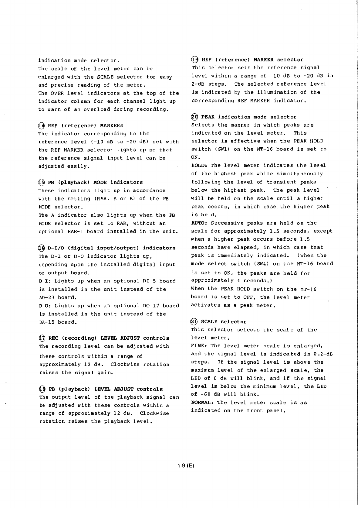
DAE-1100/llOOA
This
unit
is
audio
processor
DMR-2000/4000
automatic
digital-to-digital,
high-precision
features
also
an
unit
PCM
to
and a review
digital
is
recorded
to
digital
access
function
DTA-2000
This
of
according
PCM-1630
digital
used
audio
with a PCM-1630
and a BVU-BOODB
recorder,
search
point,
editing.
dial
audio
a
edit
function.
tape
analyzer
designed
tapes
the
status
audio
to
to a printer
processor.
to
provide
edit
an
output
signals
editor
for
digital
or
The
quick
rehearsal
error
from
fully
unit
a
data
1-4.
PRECAUTIONS
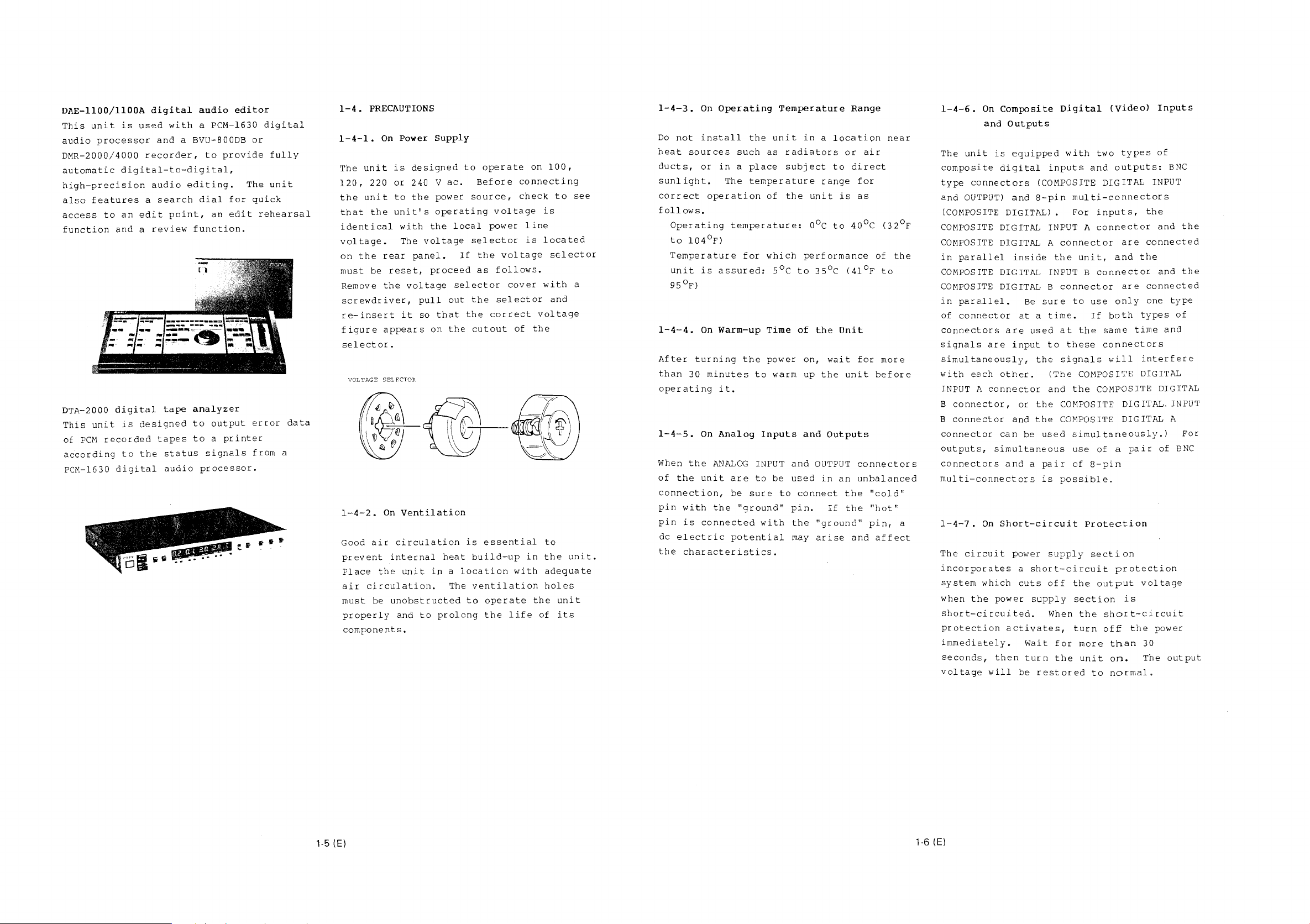
1-4-1.
The
120,
the
that
On
unit
220
unit
the
identical
voltage.
on
the
must
be
Remove
screwdriver,
re-insert
figure
selector.
VOLTAGE
l-4-2.
Good
air
prevent
Place
air
must
the
circulation.
be
properly
components.
Power
is
designed
or
240
to
the
unit's
with
The
voltage
rear
panel.
reset,
the
voltage
pull
it
so
appears
SELECTOR
On
Ventilation
circulation
internal
unit
unobstructed
and
to
Supply
to
operate
ac.
Before
source,
V
power
operating
the
local
selector
If
the
proceed
as
selector
out
the
that
the
on
the
cutout
is
essential
heat
build-up
in a location
The
ventilation
to
operate
prolong
the
voltage
power
voltage
follows.
cover
selector
correct
life
on
100,
connecting
check
is
line
is
located
with
voltage
of
the
to
in
the
with
adequate
holes
the
of
to
see
selector
a
and
unit.
unit
its
1-4-3.
Do
heat
ducts,
not
sources
On
install
or
sunlight.
correct
follows.
Operating
to
104
Temperature
unit
is
95
°F)
1-4-4.
After
than
On
turning
30
operating
1-4-5.
When
of
the
On
the
unit
connection,
pin
with
pin
is
de
electric
the
characteristics.
Operating
such
in a place
The
operation
temperature:
°F)
assured:
Warm-up
minutes
it.
Analog
ANALOG
are
be
the
connected
potential
the
as
temperature
of
for
which
Time
the
power
to
Inputs
INPUT
to
sure
"ground"
with
Temperature
unit
in a location
radiators
subject
the
unit
o0c
performance
5°C
to
of
on,
warm
up
and
and
be
used
to
connect
pin.
the
may
or
to
range
is
to
35°C
the
Unit
wait
the
unit
Outputs
OUTPUT
in
an
the
If
the
"ground"
arise
Range
air
direct
for
as
40°C
of
(41°F
for
before
connectors
unbalanced
"cold"
"hot"
pin,
and
affect
near
(32°F
the
to
more
l-4-6.
The
composite
type
and
(COMPOSITE DIGITAL) •
COMPOSITE DIGITAL INPUT A
COMPOSITE DIGITAL A
in
COMPOSITE DIGITAL INPUT B
COMPOSITE DIGITAL B
in
of
connectors
signals
simultaneously,
with
INPUT A
B
B
connector
outputs,
connectors
multi-connectors
a
l-4-7.
The
incorporates
system
when
short-circuited.
protection
immediately.
seconds,
voltage
On
and
unit
connectors
OUTPUT)
parallel
parallel.
connector
are
each
connector
connector,
connector
On
circuit
which
the
will
Composite
Outputs
is
equipped
digital
(COMPOSITE
and
S-pin
inside
Be
sure
at a time.
are
used
input
the
other.
or
the
and
the
can
be
used
simultaneous
and a pair
is
Short-circuit
power
a
short-circuit
cuts
power
supply
activates,
Wait
then
turn
be
restored
Digital
with
inputs
(Video)
two
and
DIGITAL
types
outputs:
Inputs
of
INPUT
multi-connectors
For
inputs,
connector
connector
the
unit,
connector
connector
to
use
If
both
at
the
same
to
these
signals
(The
and
connectors
will
COMPOSITE DIGITAL
the
COMPOSITE DIGITAL
are
and
are
only
the
and
connected
the
and
connected
one
types
time
interfere
and
COMPOSITE DIGITAL. INPUT
COMPOSITE
DIGITAL
simultaneously.)
use
of
of a pair
S-pin
of
possible.
Protection
supply
section
protection
off
the
When
for
the
output
section
the
turn
more
unit
to
short-circuit
off
is
the
than
on.
normal.
voltage
power
30
The
output
BNC
the
the
type
of
A
For
BNC
1-5 (E)
1-6 (E)

1-5.
LOCATION
1-5-1.
Front
@ EMPHASIS
@
MUTE
indicator---------------,
®
CRC
error
AND
FUNCTION
Panel
indicator-------------,
indicator---------.
OF
PARTS
AND
CONTROLS
SAMPLING
Level
FREQUENCY
meter
REF
MARKERs
indicators
PB
MODE
indicators
D-I/0
indicators
A:
The
composite
the
COMPOSITE
DIGITAL A
playback
board
(Read
to
selector
refer
manual
B:
the
DIGITAL B
playback
is
After
be
used
to
of
The
composite
CO~lPOSITE
digital
DIGITAL INPUT A
connector)
signal.
installed
Write)
for
to
this
the
the
connector J is
signal.
When
in
function
dubbing
position.
operation
RAR-1
digital
DIGITAL INPUT B
is
an
the
or
and
board.
A
input
or
selected
optional
unit
of
editing,
For
maintenance
B
input C input
or
selected
(input
COMPOSITE
as
a
RAR-1
and
the
the
board
set
details,
COMPOSITE
as
a
to
RAW
is
the
to
®
ENC
IN
(encoder
Selects
encoder.
ANALOG
the
DIGITAL:
ENC
connector
DUBBING:
COMPOSITE DIGITAL INPUT
DIGITAL
®
POWER
Turns
a
(D-IJ:
ANALOG
Selects
IN
connectors
Selects
connectors.
switch
the
source
INPUT
section)
power
input)
signal
Selects
connectors.
the
the
on
(in
and
selector
to
the
signals
the
signals
or
off.
the
built-in
signals
input
DIGITAL
input
COMPOSITE
input
to
I/0
to
to
the
the
®
POWER
(j)
ENC
®
MONITOR
®
HEADPHONES
0
DA
G)
MUTE
G)
LEVEL
G)
PB
switch
IN
IN
selector----------'
indication
control--------------'
MODE
----------~
selector--------
selector
jack
selector
-------•
-------
mode
selector
------------'
___j
PEAK
SCALE
([§}
PB
REF
indicafion
selector
LEVEL
MARKER
ADJUST
selector
mode
@
controls
selector
•
REC
ADJUST
...
-
'·
LEVEL
controls
0
LEVEL
Adjusts
(})!~UTE
HOLD:
the
as
AUTO:
when
G)oA
Selects
builtINT:
INPUT
COMPOSITE
selected.
EXT:
(in
selected.
@HEADPHONES
Connect
impedance.
control
the
indication
Once
MUTE
indicator
long
as
The
the
muting
IN
(digital-to-analog
the
in
D/A
Signals
connectors
Signals
the
DIGITAL
stereo
volume
the
the
MUTE
source
DIGITAL
of
mode
muting
lights
unit
indicator
circuit
signal
converter.
input
input
jack
to
(BNC
connectors
to
I/0
(stereo
headphones
the
headphones.
selector
circuit
up
is
turned
lights
activates
the
type)
the
connector
activates,
and
stays
on.
up
.
input)
to
be
sent
COMPOSITE DIGITAD
or
the
(8-pin)
DA
IN
connectors
section)
phone
with
jack)
an
only
selector
to
are
8-ohm
lit
the
are
®eRe
This
detects
~
This
circuit
setting
selector.
(cyclic
indicator
indicator
MUTE
indicator
a
indicator
activates,
of
U EMPHASIS
This
indicator
contains
de-emphasis
to
de-emphasize
signal.
~
SAMPLING
Each
indicator
the
sampling
of
the
internal
sync
signal
being
played
redundancy
lights
CRC
error
lights
the
MUTE
indicator
lights
a
pre-emphasized
circuit
the
FREQUENCY
lights
frequency
sync
(EXT)
back
up
in
the
up
depending
indication
up
of
the
detected
indicators
up,
(44.056
signal
or
signal
(FsiD)
check
when
the
playback
when
the
upon
when
signal,
unit
pre-emphasized
depending
(INT),
from
.
code)
mode
input
activates
or
the
error
unit
signal.
muting
the
data
and
upon
44.1
external
tape
the
kHz)
([}PB
(playback)
Used
to
select
PB
MODE
indicators
with
the
setting
RAR:
When
an
(DABK-1630)
RAR
(Read
After
when
signals
the
COMPOSITE DIGITAL INPUT A
MODE
the
optional
is
installed
are
of
Read)
input
selector
playback
illuminate
this
selector.
RAR-1
in
function
simultaneously
signal(s).
in
accordance
circuit
the
unit,
activate.s
and
B
board
the
to
The
connectors
and B connectors.
When
installed,
when
MODE
1-7 (E)
an
this
"A"
or
RAR-1
the
selector
indicator
to
the
circuit
unit
COMPOSITE DIGITAL A
board
operates
is
set
illuminates).
to
is
the
"A"
not
same
(the
as
PB
@)MONITOR
REC:
Selects
re~orded
indication.
PB:
Selects
monitoring
selector
for
the
and
the
audio
monitoring
audio
level
signals
and
playback
meter
to
level
signals
indication.
be
meter
for
Q]J
The
to
during
during
of
1-8 (E)
Level
indicators
indicate
recording,
playback,
the
MONITOR
meter
the
on
the
input
and
depending
selector
level
level
the
and
meter
of
each
recorded
upon
the
light
the
PEAK
up
channel
level
setting
indication
The
scale
enlarged
and
precise
The
OVER
indicator
to
warn
~
REF
The
indicator
reference
the
REF
the
reference
adjusted
~
PB
These
with
the
MODE
selector.
mode
of
with
level
column
of
(reference)
level
MARKER
easily.
(playback)
indicators
setting
The A indicator
MODE
selector
optional
~
D-I/0
The
depending
or
output
D-1:
is
installed
AD-23
D-0:
is
installed
DA-15
~
REC
The
these
RAR-1
(digital
D-I
or
Lights
board.
Lights
board.
(recording)
recording
controls
D-0
upon
board.
approximately
raises
~
The
be
range
rotation
the
PB
(playback)
output
adjusted
of
approximately
raises
selector.
the
level
the
reading
indicators
for
an
overload
corresponding
(-10
selector
signal
MODE
light
(RAR, A
also
is
set
board
indicator
the
up
when
in
the
up
when
in
the
level
within
12
dB.
signal
LEVEL
level
with
of
these
the
meter
SCALE
of
selector
the
at
each
channel
during
MARKERs
dB
to
lights
input
indicators
up
in
or
lights
to
RAR,
installed
input/output)
lights
installed
an
optional
unit
instead
an
optional
unit
instead
LEVEL
can
a
ADJUST
be
range
Clockwise
gain.
ADJUST
the
playback
controls
12
dB.
playback
can
meter.
the
recording.
to
the
-20
dB)
up
level
accordance
Bl
of
up
when
without
in
indicators
up,
digital
DI-S
D0-17
controls
adjusted
of
controls
within
Clockwise
level.
be
for
top
light
set
so
can
the
the
the
of
the
of
the
with
rotation
signal
easy
of
with
that
be
PB
an
unit.
input
board
board
a
the
up
PB
can
~
REF
(reference)
This
selector
level
2-dB
is
within
steps.
indicated
corresponding
~
PEAK
indication
Selects
indicated
selector
switch
the
on
is
(SWl)
ON.
The
BOLD:
of
the
following
below
will
peak
is
held.
AUTO:
scale
level
highest
the
the
highest
be
held
occurs,
Successive
for
approximately
when a higher
seconds
peak
mode
is
is
select
set
have
immediately
to
ON,
approximately
When
the
PEAK
board
activates
~
This
level
FINE:
and
steps.
maximum
LED
level
of
NORMAL:
indicated
is
SCALE
selector
meter.
The
the
of
is
-60
set
as a peak
selector
level
signal
If
level
0 dB
below
dB
will
The
on
sets
a
range
The
by
REF
manner
the
effective
on
peak
level
on
in
peak
elapsed,
switch
the
4
HOLD
to
selects
level
the
signal
of
will
the
blink.
level
the
MARKER
the
of
selected
the
illumination
MARKER
mode
in
level
the
MT-16
meter
while
of
peak.
the
scale
which
peaks
occurs
indicated.
(SW4l
peaks
seconds.)
switch
OFF,
the
meter.
meter
is
the
enlarged
blink,
minimum
meter
front
selector
reference
-10
reference
indicator.
selector
which
meter.
when
the
board
indicates
simultaneously
transient
The
until
case.
the
are
held
1.5
before
in
which
on
are
on
level
the
scale
scale
indicated
level
and
level,
scale
panel.
dB
to
of
peaks
This
PEAK
is
the
peaks
peak
a
higher
on
seconds,
1.5
case
(When
the
MT-16
held
the
meter
of
is
enlarged,
is
above
scale,
if
the
is
as
signal
-20
level
the
are
HOLD
set
level
level
higher
the
that
for
MT-16
the
in
signal
the
dB
to
peak
except
the
board
0.2-dB
the
th~
LED
in
1-9 (E)
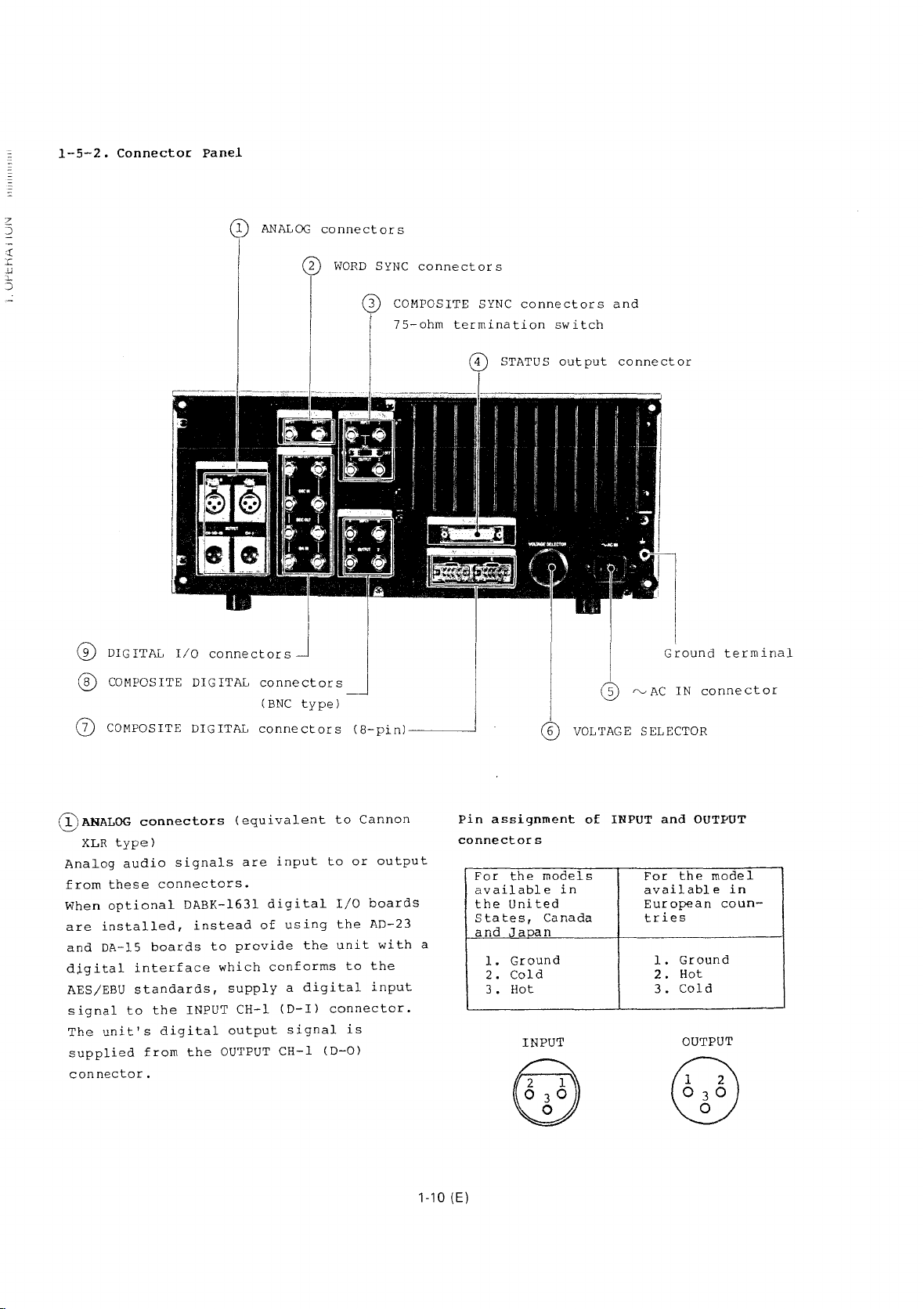
1-5-2.
Connector
Panel
G)
DIGITAL
I/O
connectors
® COMPOSITE DIGITAL
(j) COMPOSITE DIGITAL
ANALOG
connectors
(BNC
type)
connectors
connectors
WORD
(8-pin)----_j
SYNC
connectors
COMPOSITE
75-ohm
SYNC
termination
STATUS
connectors
switch
output
VOLTAGE
and
connector
"--'
AC
SELECTOR
Ground
IN
terminal
connector
(})ANALOG
XLR
Analog
from
these
When
optional
are
installed,
and
DA-15
digital
AES/EBU
signal
The
unit's
supplied
connector.
connectors
type)
audio
interface
standards,
to
from
signals
connectors.
DABK-1631
instead
boards
the
INPUT
digital
the
(equivalent
are
to
provide
which
supply
CH-1
output
OUTPUT
input
digital
of
using
conforms
a
(D-I)
signal
CH-1
to
the
digital
connector.
(D-0)
to
I/0
the
unit
to
is
Cannon
or
output
boards
AD-23
with
the
input
a
1-10
Pin
assignment
connectors
For
available
the
States,
and
l.
2.
3.
(E)
the
United
Jaoan
Ground
Cold
Hot
INPUT
models
in
Canada
of
INPUT
and
the
For
available
European
tries
Ground
l.
Hot
2.
Cold
3.
OUTPUT
u
\J(J
OUTPUT
model
in
coun-

@WORD
A
kHz
connector
OUTPUT
@coMPOSITE
These
INPUT
OUTPUT
sync
connectors
termination
termination
looping
@STATUS
Signals
as
connector.
except
open-collectors.
Pin
word
is
75-ohm
connectors
1,
signal.
type)
error
assignment
Pin
No.
1
2
3
4
5
6
7
8
9
10
11
12
13
14
15
16
17
18
19
20
21
22
23
24
25
SYNC
sync
input
connector.
termination
2)
1,
output
output
containing
flags,
for
connectors
signal
to
or
output
SYNC
and
2)
connectors
To
with
switch
switch
The
the
Sianal
GND
A/B
REC/PB
FG
HLD
GND
GND
---
AVE
GND
CRC
GND
FsiD
EMP
GND
MUTE
WCLK
WCLK
BCLK
BCLK
ME
ME
ME
ME
PAR
of
the
WORD
from
connectors
are
output
terminate
75
ohms,
to
to
(bridge
connector
status
are
output
connector's
RS-422
CH-1
CH-1
CH-2
CH-2
(BNC
type)
44.1
kHz
SYNC
INPUT
the
WORD
(BNC
switch
input
}word
}Bit
} CH-1
JCH-2
(COMPOSITE
(COMPOSITE
for a composite
the
set
the
ON.
Set
OFF
to
create
connection).
(25-pin
information,
from
output
circuits
Remarks
Ground
A/B
Frame
Hold
Ground
Ground
N. c.
Average
Ground
CRC
Ground
44.056
44.1
Emphasis
Ground
Muting
(25-slot)
(25-slot)
(25-slot)
Pari
for
select
ground
for
for
for
error
for
kHz:
kHz:
for
clock
clock
data
data
tv
error
or
44.056
SYNC
type)
SYNC
INPUT
75-ohm
the
D-sub
this
have
A/B
HLD
PAR
AVE
--
CRC
'L'
ON:
MUTE
SYNC
a
circuits
'H'
'H'
RS-
422
and
such
QD~Ac
Connect
ac
@VOLTAGE SELECTOR
The
set
voltage
selector,
G)coMPOSITE
COMPOSITE DIGITAL A:
input
COMPOSITE DIGITAL INPUT A
inside)
COMPOSITE DIGITAL
digital
the
inside)
Pin
Note:
digital
@coMPOSITE
COMPOSITE DIGITAL INPUT A:
digital
COMPOSITE DIGITAL INPUT
composite
COMPOSITE DIGITAL
Independent
IN
(input)
to
an
power
18-pin
Pin
type)
cord.
operating
to
100,
120,
selector.
refer
DIGITAL
multi-connectors)
(connected
and
composite
input
COMPOSITE DIGITAL INPUT B
and
composite
assignment
No.
1
2
3
4
5
6
7 SEL
8
"SEL"
s~nal
c.
c.
is a signal
master
40
X X
0
8
DIGITAL
input.
digital
composite
connector
ac
outlet
voltage
220
To
to
1-4-1.
(video)
in
parallel
B:
(connected
---
D.
IN
GND
D.
OUT
---
GND
---
recorder.
30
20
0
60
7 5
input.
OUTPUT 1 ana
of
or
reset
Main
digital
Auxiliary
digital
Composite
input
Ground
OUT
Composite.
output
Ground
IN
Connect
(video)
digital
using
the
unit
240 v ac
the
connectors
composite
with
connector
in
parallel
Remarks
c.
N.
for
c.
N.
for
c.
N
for
a
10
0
connectors
Main
B:
Auxiliary
the
supplied
can
with
voltage
digital
the
®
output.
composite
connector
output.
digital
D.
c.
digital
D.
c.
ground
to
DMR-2000
composite
2:
outputs.
be
this
with
®
(BNC
1-11
(E)
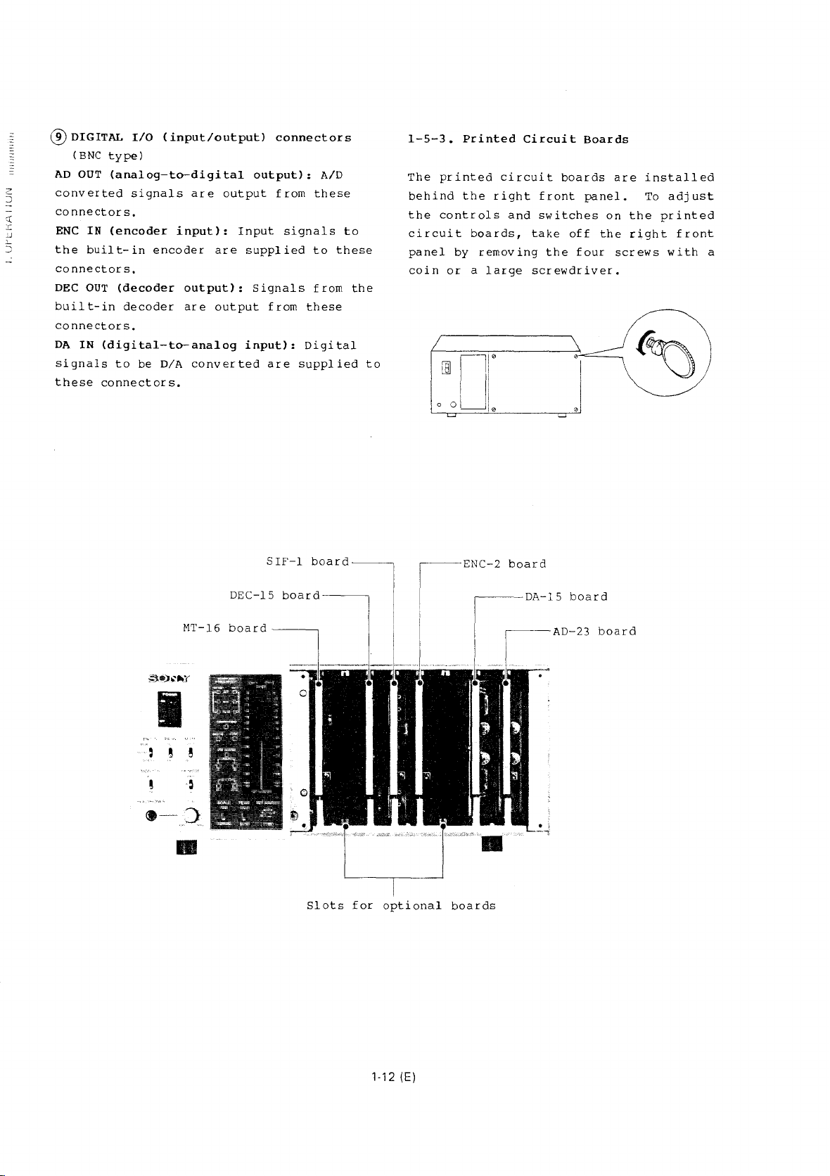
®DIGITAL
(BNC
AD
OUT
converted
connectors.
ENC
IN
the
built-in
connectors.
DEC
OUT
built-in
connectors.
DA
IN
(digital-to-analog
signals
these
connectors.
I/0
(input/output)
type)
(analog-to-digital
signals
(encoder
(decoder
decoder
to
be
input):
encoder
output):
are
D/A
are
converted
output
Input
are
output
connectors
output):
from
supplied
Signals
from
input):
are
these
signals
to
from
these
Digital
supplied
AID
to
these
the
to
1-5-3.
The
behind
the
circuit
panel
coin
I 0
printed
controls
or a large
~
LJ
Printed
the
boards,
by
removing
Circuit
circuit
right
and
take
screwdriver.
Ji"
OLJI.
boards
front
switches
off
the
four
Boards
panel.
on
the
are
the
right
screws
installed
To
adjust
printed
front
with
a
I
~lT-16
SIF-1
DEC-15
board---------,
board----~
board----~
Slots
for
I
optional
-ENC-2
boards
board
DA-15
~-----AD-23
board
board
1-12 (E)

A0-23
board
Emphasis
The
setting
affect
the
output
selector
particular
following
the
setting
emphasis
follows.
identification
of
the
emphasis
signal
on
the
position,
table.
of
identification
the
data
front
The
the
bits
EMP
switch
identification
when
panel
as
shown
relationships
ENC
IN
selector
bits
the
is
are
does
ENC
set
in
the
as
not
bits
IN
to
a
between
and
in
the
@mil:
This
(OFF)
recording.
When
high-frequency
automatically
(pre-emphasis,
psec./15
noise
(the
response
When
is
The
(]
This
(OFF)
When
is
order
the
the
when
This
made
EMP
&W2:
mixed
dither
noise
EMP
switch
the
this
and
boosted
this
with
switch
Dither
switch
the
this
to
the
switch
(emphasis)
activates
emphasis
switch
psec.)
improve
is
switch
dither
switch
with a low
suppress
level
level
switch
is
response
during
with a time
to
amount
lowered
is
the
flat
is
switch
activates
generator
is
is
will
is
is
factory
switch
(ON)
circuitry
set
recording
reduce
the
signal-to-noise
is
detected
during
set
frequency
factory
(ON)
set
level
audible
set
be
set
to
preset
or
to
ON,
is
boosted
constant
the
playback).
to
OFF, a
preset
or
circuit.
to
ON,
input
noise.
at
less
raised
ON.
deactivates
during
the
amount
and
recording
response.
to
deactivates
the
dither
signal
Although
than 1 LSB
somewhat
to
OFF.
of
of
ratio
the
OFF.
50
in
~Output
I\
signal
ENC
IN\
sel
ec-
tor
ANALOG
DIGITAL
DUBBING
*
In
the
E-to-E
emphasis
of
the
emphasis
the
signal
DIGITAL INPUT
AD
OUT
connec-
tor
ON/OFF
of
the
EMP
switch
on
the
AD
board
ON/OFF
of
the
EMP
SWitch
on
the
AD
board
ON/OFF
of
the
EMP
switch
on
the
AD
board
depends
data
COMPOS-
ITE
DIG-
ITAL
OUTPUT
connector
ON/OFF
of
the
EMP
switch
on
the
AD
board
ON/OFF
of
the
emphasis
bits
the
digital
signal
data
input
the
ENC
IN
connector
ON/OFF
of
the
emphasis
bits
the
sig-
na-l
data
input
the
COM-
POSITE
DIGITAL
INPUT
connector
or
playback
upon
the
identification
input
connector(s).
to
in
to
in
to
the
DEC
connector
Ir
rele-
vant*
I r
rele-
vant*
ON/OFF
of
emphasis
bits
the
nal
input
the
POSITE
DIGITAL
INPUT
connector
mode,
ON/OFF
COMPOSITE
OUT
the
sig-
data
COM-
the
bits
in
to
status
in
1-13 (E)
The
de-emphasis
activated
depending
,
5
r
[
cJ
selector
DA
selector
(ON)
upon
as
IN
)
INT
EXT
circuit
or
deactivated
the
setting
shown
ON/OFF
below.
status
de-emphasis*
ON/OFF
sis
the
the
INPUT
ON/OFF
sis
the
the
DIGITAL
status
identification
signal
data
COMPOSITE DIGITAL
connector
status
identification
signal
DA
IN
connectors
data
I/0
for
playback
of
of
of
the
input
of
the
input
connector
(OFF),
the
the
em
bits
empha
bits
in
DA
ph
to
to
sec-
is
IN
a
in
in
the
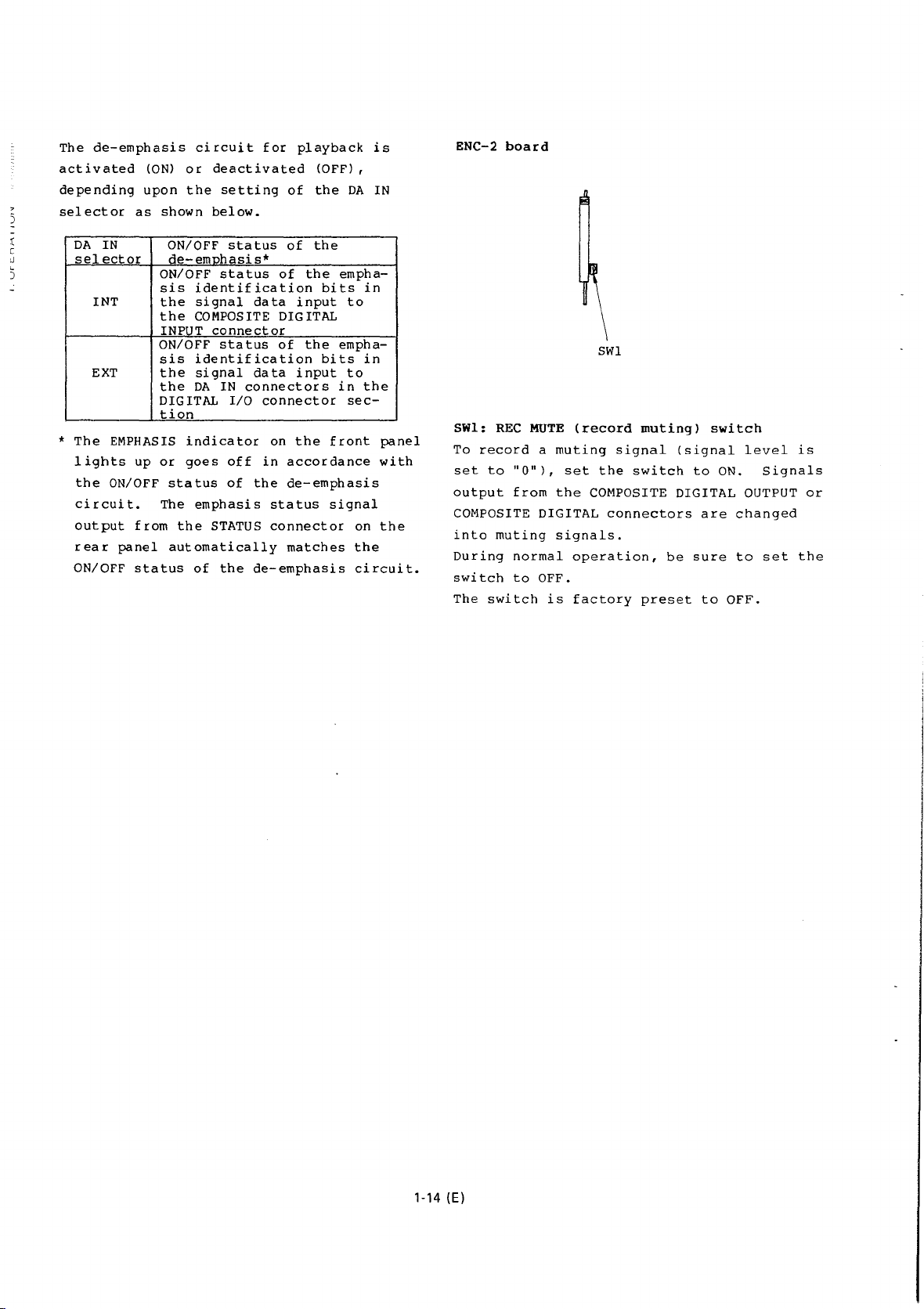
ENC-2
board
SWl
tion
SWl:
REC
MUTE
*
The
lights
the
circuit.
output
rear
ON/OFF
EMPHASIS
up
or
ON/OFF
The
from
panel
status
indicator
goes
off
status
of
emphasis
the
STATUS
automatically
of
the
on
the
in
accordance
the
de-emphasis
status
connector
matches
de-emphasis
front
signal
on
the
circuit.
panel
with
the
(record
To
record
set
output
to
"0"1,
from
a
muting
the
set
COMPOSITE DIGITAL OUTPUT
COMPOSITE DIGITAL
into
During
switch
The
switch
muting
normal
to
OFF.
signals.
operation,
is
factory
muting)
signal
the
switch
connectors
preset
(signal
be
to
are
sure
to
switch
ON.
changed
to
OFF.
level
Signals
set
is
or
the
1-14 (E)
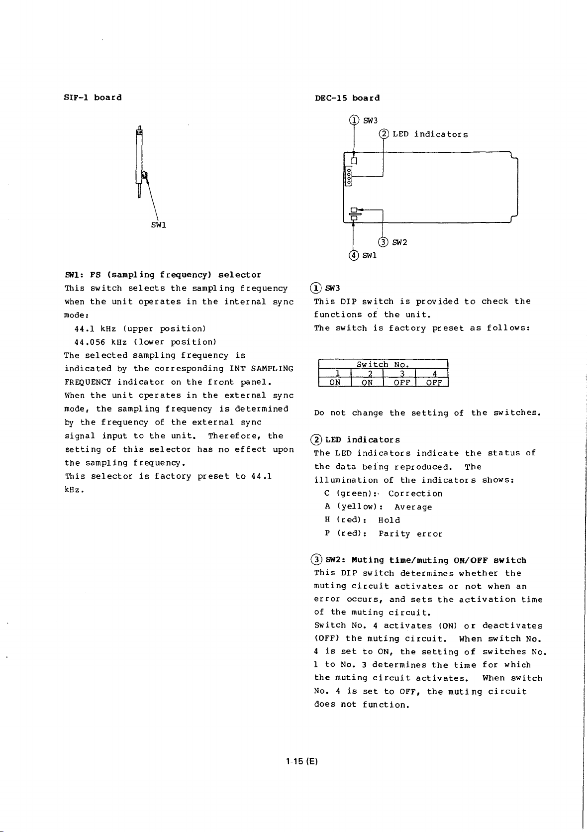
SIF-1
mode:
The
When
mode,
by
board
SHl:
FS
This
switch
when
the
44.1
kHz
44.056
selected
indicated
FREQUENCY
the
the
the
frequency
signal
setting
the
This
kHz.
input
sampling
selector
(sampling
selects
unit
(upper
kHz
(lower
sampling
by
the
indicator
unit
sampling
to
of
this
frequency.
SWl
frequency)
the
operates
position)
position)
corresponding
on
operates
frequency
of
the
selector
is
factory
sampling
in
frequency
the
in
the
external
unit.
selector
the
front
the
is
Therefore,
has
no
preset
frequency
internal
is
INT
SAMPLING
panel.
external
determined
sync
effect
to
44.1
sync
sync
the
upon
DEC-15
@sw3
This
DIP
functions
The
switch
Do
not
@LED
The
LED
the
data
illumination
C
(green):·
A
(yellow):
H
(red):
P
(red):
board
switch
of
is
change
indicators
indicators
being
Hold
Parity
LED
indicators
is
provided
the
unit.
factory
the
setting
reproduced.
of
the
Correction
Average
preset
indicate
indicators
error
of
to
as
the
the
The
check
follows:
switches.
status
shows:
the
of
Q)
1-15 (E)
SW2:
Muting
This
DIP
muting
error
of
Switch
(OFF)
4
1
the
No. 4 is
does
circuit
occurs,
the
muting
No. 4 activates
the
is
set
to
No. 3 determines
muting
not
time/muting
switch
and
circuit.
muting
to
ON,
circuit
set
to
function.
determines
activates
sets
circuit.
the
setting
activates.
OFF,
the
the
or
the
(ON)
muting
ON/OFF
whether
not
activation
or
When
of
time
switch
the
when
an
deactivates
switch
switches
for
which
When
switch
circuit
time
No.
No.
-
=
z
0
i=
<{
cc
w
a..
0
The
muting
No. 1
range
2
to
is
seconds.
Switch
1
X X X
OFF
OFF OFF
OFF
ON
OFF
ON
ON
ON
OFF
OFF
OFF
ON
OFF
ON
ON
ON
x = any
When
the
slight
noise
digital
DIGITAL
connectors
recommend
OFF
during
The
muting
factory
Muting
Muting
time
No. 3
from
3
2
OFF
OFF
OFF
ON
ON
ON
ON
position
muting
will
signals
or
COMPOSITE
have
not
normal
time/muting
preset
circuit:
time:
(switch
switches
can
be
set
as
follows.
1/60
seconds
No
4
OFF
ON
ON
ON
ON
ON
ON
ON
ON
circuit
occur
input
to
DIGITAL
errors.
setting
the
operation.
ON/OFF
as
follows:
ON
approx. 1 sec.
No.
1:
No. 2
with
switches
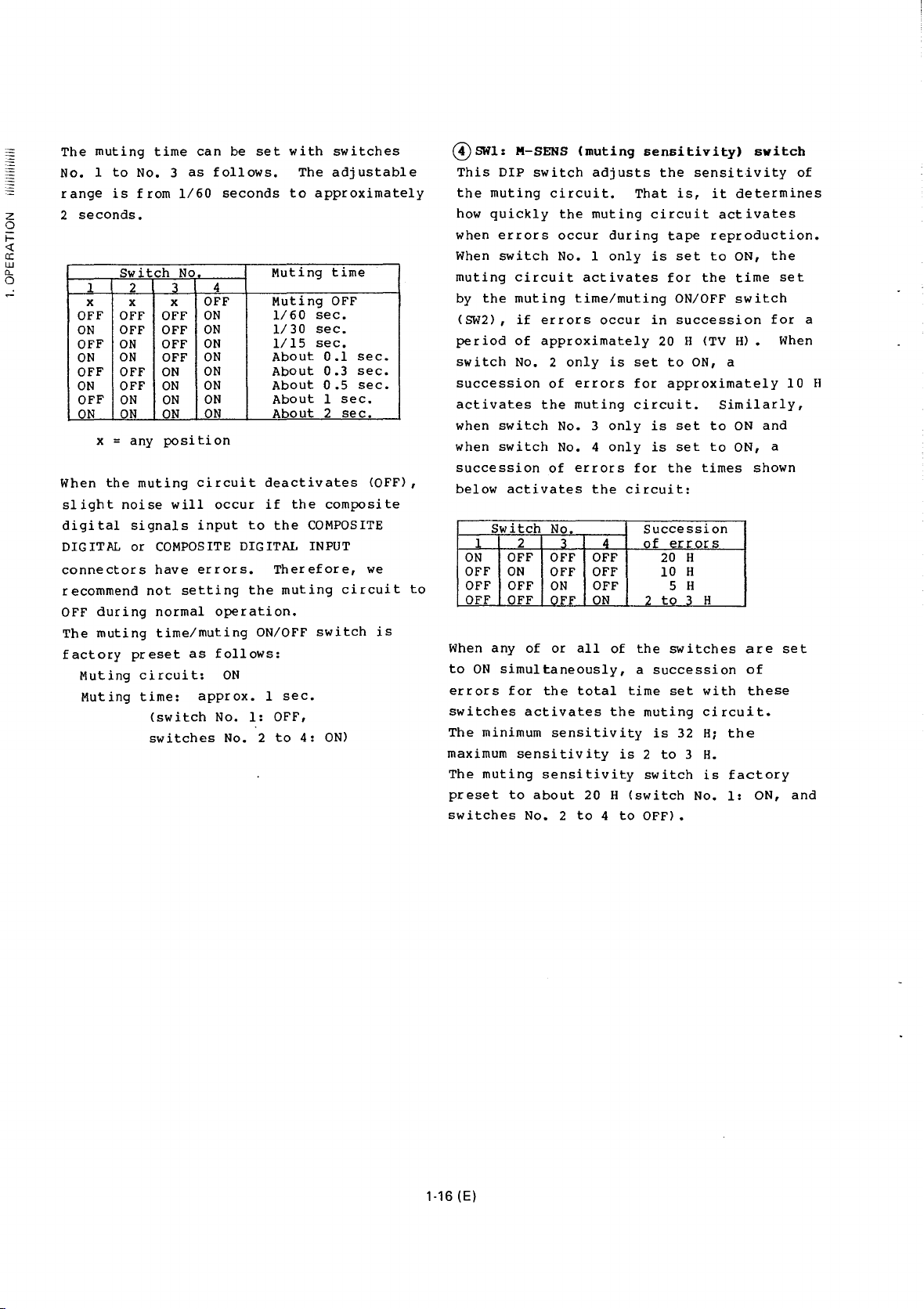
The
adjustable
to
approximately
Muting
Muting
1/60
1/30
1/15
About
About
About
time
OFF
sec.
sec.
sec.
0.1
0.3
0.5
About 1 sec.
About 2 sec.
deactivates
if
the
composite
the
COMPOSITE
INPUT
Therefore,
muting
circuit
switch
OFF,
to
4:
ON)
sec.
sec.
sec.
(OFF),
we
is
to
G)swl:
This
the
how
when
When
muting
by
(SW2),
period
switch
M-SENS
DIP
muting
quickly
errors
switch
circuit
the
muting
if
of
No. 2
switch
errors
approximately
succession
activates
when
when
the
switch
switch
succession
below
activates
Switch
1 2 3 4
OFF
ON
OFF
ON
OFF
OFF
OFF
OFF
When
any
of
to
ON
simultaneously,
errors
switches
The
maximum
The
preset
switches
for
activates
minimum
sensitivity
muting
to
No. 2
the
sensitivity
about
(muting
adjusts
circuit.
the
muting
occur
No. 1
activates
time/muting
occur
only
of
errors
muting
No. 3
No. 4
of
errors
the
No.
OFF
OFF
OFF
OFF
ON
OFF
ON
OFF
or
all
total
sensitivity
20 H
to 4 to
sensitivity)
the
That
is,
circuit
during
only
is
tape
set
for
ON/OFF
in
succession
20 H (TV
is
set
to
for
approximately
circuit.
only
is
set
only
is
set
for
the
circuit:
Succession
of
errors
20
H
10 H
5 H
2
to
3 H
of
the
switches
a
succession
time
set
the
muting
is
32
is 2 to 3 H.
switch
<switch
OFF).
sensitivity
it
determines
activates
reproduction.
to
ON,
the
time
switch
H) • When
ON,
a
Similarly,
to
ON
to
ON, a
times
are
of
with
these
circuit.
H;
the
is
factory
No.
1:
switch
the
set
for
10
and
shown
set
ON,
of
a
H
and
1-16 (E)

MT-16
board
0
SW2
for
channel 1 and
Overload
3
SW4
These
of
full-scale
continuously
indicated
the
level
for
each
DIP
indication
switches
signals
input
with
meter.
channel
the
Up
with
SW3
adjustment
set
the
(overload
to
the
OVER
level
to 8 words
these
for
number
unit,
switches.
channel
switches
of
signals)
which
indicator
can
be
2:
words
are
on
set
(!) SWl:
This
level
peak
ON:
hold
is
PEAK
switch
meter
meter.
The
level
meter.
indicated
approximately
indication
is
set
to
occurs
when
selector
This
switch
OFF:
The
level
meter.
setting
When
of
selector
upon
the
levels
the
are
PEAK
HOLD.
BOLD
selects
--
as a peak
meter
The
and
1.5
mode
AUTO,
on
the
the
is
or
PEAK
front
factory
meter
this
the
PEAK
on
the
front
level
not
meter
held
indication
switch
the
functions
level
held
seconds
selector
until
indication
functions
switch
indication
indication,
on
mode
function
hold
of
on
the
on
a
panel
preset
is
panel
the
selector
the
scale
when
the
higher
is
set
has
scale
of
the
meter
or
as a peak
highest
for
the
PEAK
front
peak
mode
set
to
to
ON.
as a peak
to
OFF,
mode
no
effect
and
peak
even
is
set
a
peak
panel
HOLD.
the
if
to
~--~-.~~~~~~~--~--~--~umber
These
words
4
Q)
This
indication
time
w)1ether
held
switches
(Nos. 1 to 3 are
to
8 OFF.)
SW4:
Mode
DIP
switch
and
release
the
or
not.
·switch
Indication
No
1
Peak
time
Release
2
time
are
select
modes.
overload
mode
hold
factory
switch
selects
It
time,
preset
set
to
the
sets
the
and
determines
indication
Switch
ON
About
4
sec.
About
100
f
ON,
level
peak
is
r:osition
About
1.5
About
50
words
1
2
3
4
5
6
7
8
to
and
meter
hold
to
OFF
sec.
msec.
3
Nos.
be
msec
3
to
4
Overload
level
R
Not
Not
held
used
Held
All
1-17 (E)
the
switches
are
factory
preset
to
OFF.
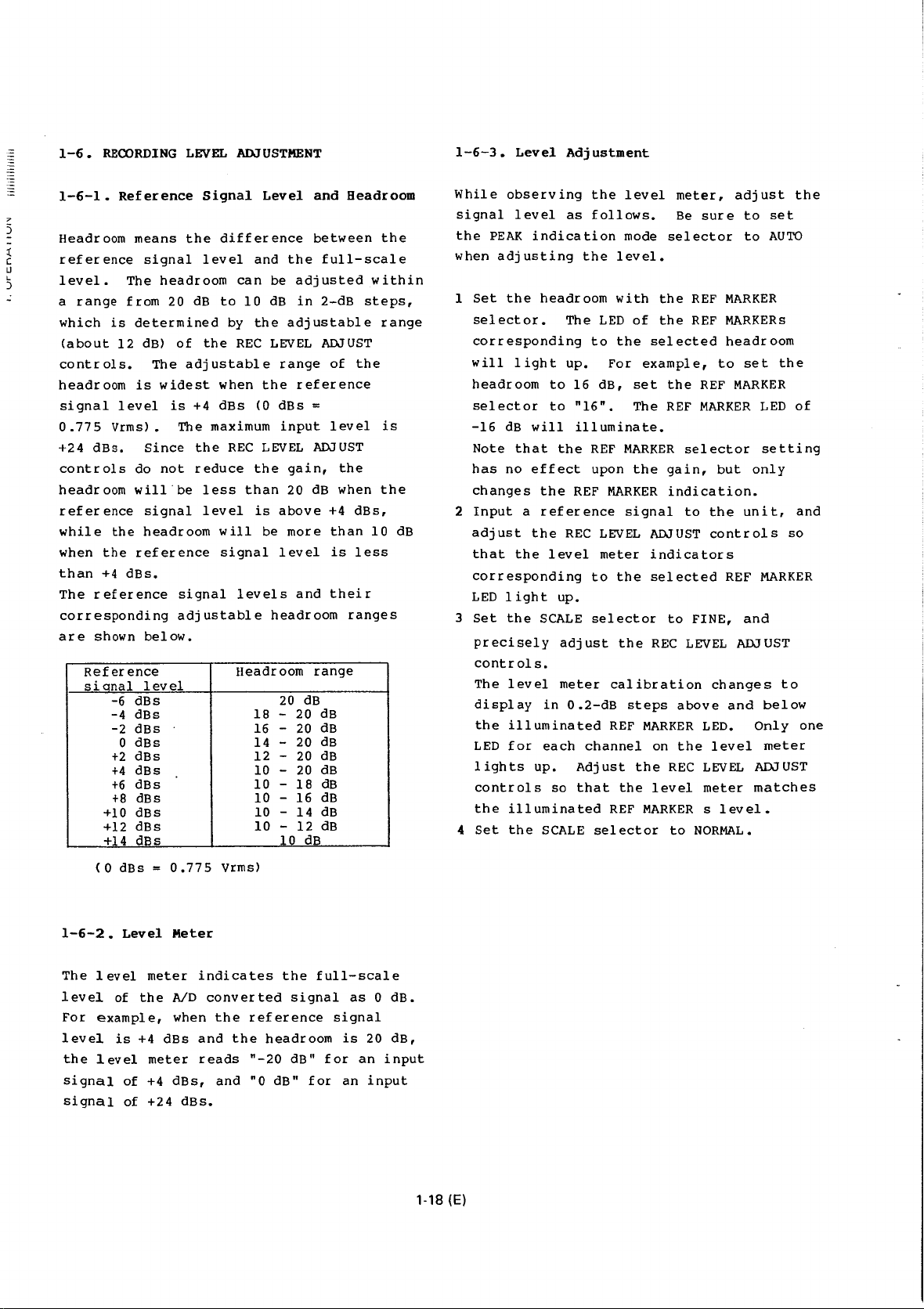
1-6.
RECORDING
LEVEL
ADJUSTMENT
1-6-3.
Level
Adjustment
1-6-1.
7
5
:(
c
Ll
)
"
.:
Headroom
reference
level.
a
which
(about
controls.
headroom
signal
0.775
+24
controls
headroom
reference
while
when
than
The
corresponding
are
Reference
range
is
12
level
Vrms).
dBs.
the
the
+4
reference
shown
Reference
sional
-6
-4
-2
0
+2
+4
+6
+8
+10
+12
+14
means
signal
The
headroom
from
20
determined
dB)
of
The
is
widest
is
Since
do
not
will
signal
headroom
reference
dBs.
below.
level
dBs
dBs
dBs
dBs
dBs
dBs
dBs
dBs
dBs
dBs
dBs
Signal
the
difference
level
dB
to
by
the
adjustable
when
+4
dBs
The
maximum
the
REC
reduce
be
less
level
will
signal
signal
adjustable
Level
and
the
can
be
10
dB
the
adjustable
REC
LEVEL
range
the
(0
dBs
input
LEVEL
the
gain,
than
20
is
above
be
more
level
levels
headroom
Headroom
20
18
-
16
- 20 dB
14
-
12
- 20
10
-
-
10
-
10
-
10
10 -12
10
and
between
full-scale
adjusted
in
2-dB
ADJUST
of
reference
=
level
ADJUST
the
dB
when
+4
than
is
and
their
range
dB
20
dB
20
dB
dB
20 dB
18
dB
16
dB
14
dB
dB
dB
Headroom
the
within
steps,
range
the
is
the
dBs,
10
dB
less
ranges
While
signal
the
when
1
2
3
4
observing
level
PEAK
indication
adjusting
Set
the
headroom
selector.
corresponding
will
light
headroom
selector
-16
dB
will
Note
that
has
no
effect
changes
Input
adjust
that
a
the
the
the
reference
corresponding
LED 1 ight
Set
the
SCALE
precisely
controls.
The
level
display
the
LED
lights
in
illuminated
for
each
up.
controls
the
illuminated
Set
the
SCALE
as
The
up.
to
16
to
"16".
illuminate.
the
REF
REC
level
up.
adjust
meter
0.2-dB
Adjust
so
that
the
follows.
the
level.
with
LED
to
the
For
dB,
REF
upon
MARKER
LEVEL
meter
to
the
selector
calibration
REF
channel
REF
selector
level
meter,
Be
mode
selector
the
REF
of
the
REF
selected
example,
set
the
The
REF
MARKER
the
selector
gain,
indication.
signal
to
ADJUST
indicators
selected
to
FINE,
the
REC
LEVEL
steps
above
MARKER
on
the
the
REC
the
level
MARKER s level.
to
NORMAL.
adjust
sure
to
to
MARKER
MARKERs
headroom
to
set
REF
MARKER
MARKER
but
the
unit,
controls
REF
and
ADJUST
changes
and
LED.
level
LEVEL
meter
set
AUTO
the
LED
setting
only
so
MARKER
to
below
Only
meter
ADJUST
matches
the
of
and
one
( 0
dBs
1-6-2.
The 1 evel
level
For
level
the
of
example,
is
level
signal
signal
Level
meter
the
+4
of
+4
of
+24
0.775
Meter
AID
when
dBs
meter
dBs,
indicates
converted
and
reads
dBs.
vrms)
the
the
and
the
signal
reference
headroom
"-20
dB"
"0
dB"
full-scale
signal
is
for
for
an
as 0 dB.
20
dB,
an
input
input
1-18 (E)

1-7.
CONNECTIONS
1-7-1.
An
recording
For a recording
the
the
(video)
as
For a playback
connection
mode:
(video)
the
the
the
Recording
example
COMPOSITE DIGITAL
PCM-1630
the
COMPOSITE DIGITAL INPUT A
PCM-1630
PCM-1630
75-ohm
(
1-551-475-51)
of a basic
and
input
DMR-2000/4000,
for
Connect
output
coaxial
AND
and
playback
signal
to
the
connector
signal
monitoring
the
connector
(set
the
to
A) (
cables
composite
composite
0).
OPERATION
Playbac~
connection
is
shown
connection:
OUTPUT
BVU-800DB (
connection
PB
connector
digital
of
recorders
in
the
digital
of
the
connector
MODE
selector
(BNC-BNC)~~~
for
below.
Connect
such
0).
or
E-to-E
recorder
of
of
of
to
When a DMR-2000
used
in
the
system,
can
be
replaced
with
an
8-pin
case,
simultaneously.
Notes
•
•
do
not
Since
to
during
digital
from
The
alternated
buttons
BVU-800DA/DB
the
circuit
ON.
the
the
sync
playback,
the
recording
recorder's
recorder's
signal
PCM-1630
on
to
VMC-3P
make
by
the
OFF
(l-534-392-11)
or
DMR-4000
connections
with a single
multi-cable
connections
servo
signal
recorder
from
supply a composite
or a composite
to
the
and
playback
pressing
recorder.
is
dropout
and
its
Setting
ENC
DA
PB
IN
IN
MODE
8-pin
of
selector:
selector:
recorder
connection
(
®).
0
must
the
PCM-1630
recorder.
modes
the
appropriate
When a
used,
compensator
framing
the
selectors
selector:
multi-cable
0
In
and
be
sync
can
always
servo
ANALOG
INT
A
is
and
this
@
locked
signal
be
to
0
set
1-7-2.
When
and a recorder
the
without
the
For a connection
playback
(D
player.
for
For a connection
recording
PCM-1630
G).
connect
connector
output
with
To
Set
follows:
Set
recorder
dubbing
two
system,
following
shown
the
For
®.
duplicate
the
ENC
IN
DA
IN
PB
MODE
the
Digital
recorders
degrading
signal
below
For a reference
servo,
signal
and
playback
the
of
connector
selectors
selector:
selector:
selector:
player
to
will
Dubbing
(a
recorder
for
recording)
a
tape
can
be
the
sound
connections.
vith
a
player:
connection,
between
make
vith
connection,
the
recorder
COMPOSITE DIGITAL INPUT B
the
PCM-1630
of
to
the
record
begin.
connection
a
after
the
on
the
DUBBING
INT
A
the
playback
the
signal
recorder:
digital
recorder
PCM-1630
mode.
for
are
duplicated
quality.
make
PCM-1630
connection
0
connect
as
shown
dubbing,
to
the
mode
Digital
playback
used
For
connection
or
For
with
video
as
as
in
Make
a
and
® .
a
the
shown
and
the
the
To
play
back
It
is
possible
tape
simply
on
the
PCM-1630
connections.
on
the
PCM-1630
recommended.
Notes
•
For
digital
(SWll
to
accordance
(indicated
front
on
•
The
tape
the
the
of
dubbing.
• When
(the
dubbing
recording
may
malfunction.
the
on
the
panel
the
player.
emphasis
being
tape
EMP
the
PCM-1630
the
stop
oscillate
volume
the
to
by
setting
to
(Setting
to
l
dubbing,
the
SIF-1
appropriate
with
by
the
of
identification
played
in
the
switch
recorder
model
operation,
signal
noise.
When
to
avoid
11=11
)EBE::9)
duplicated
play
back
the
B,
without
the
ANALOG
set
board
position,
the
sampling
FsiD
the
PCM-1630)
back
recorder.
(SWll
does
is
during
a
and
this
on
not
in
loop
the
speaker
(@)
tape
the
PB
ENC
or
DIGITAL
the
of
indicator
are
recorded
The
the
affect
the
the
digital
of
playback
This
is
~ccurs,
D o
duplicated
MODE
changing
IN
selector
FS
selector
the
PCM-1630
in
frequency
of
the
bits
setting
AD-23
digital
E-to-E
the
not
turn
damage.
selector
the
is
on
the
tape
on
the
on
board
mode
signal
a
down
of
0
1-19 (E)
DMR-2000
(or
DMR-4000,
recorder,
recorder
BVU-800DA/DB
etc.
)
*
Connection
instead
which
the
the
CD
of
is
capstan
player.
Audio
@
connection
made
servo
output
can
only
of
be
for
signals
made
0
{ CH-1
CH-2
--
......
Player:
--~
r--------'
@
BVU-800DA/DB
(or
1-20 (E)
I
I
I
I
®*.
DMR-2000)
PCM-1630
G)
Recorder:
Protector
0 0
~ 0 ~§~
BVU-800DA/DB
(or
DMR-2000)
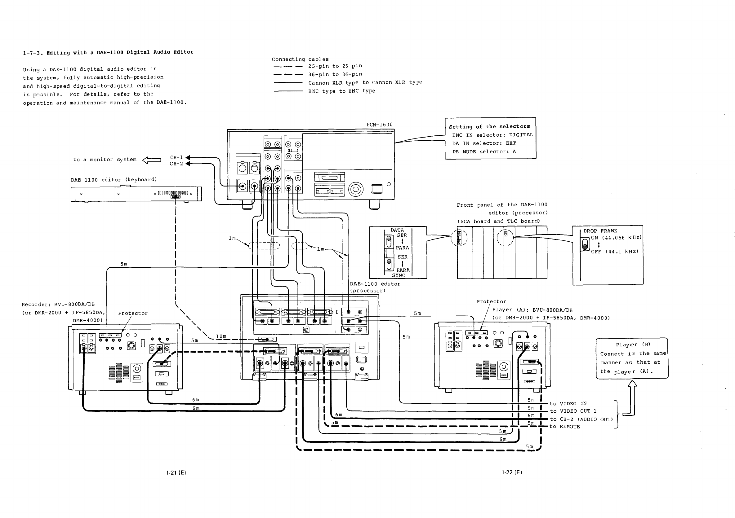
1-7-3.
Using a DAE-1100
the
and
is
operation
Editing
system,
high-speed
possible.
fully
and
maintenance
For
with a DAE-1100
digital
automatic
digital-to-digital
details,
audio
high-precision
refer
manual
Digital
editor
editing
to
of
Audio
in
the
the
Editor
DAE-1100.
Connecting
--
---
-
cables
25-pin
36-pin
Cannon
BNC
type
to
to
XLR
25-pin
36-pin
type
to
BNC
to
type
Cannon
XLR
type
Recorder:
(or
DMR-2000 +
CH-1
to a monitor
DAE-1100
editor
system
(keyboard)
~
<1111~&-----
C H-2
<1111~1-----
=
0
u
0
ooooooooooooooooo
0
~w
II
lm~~
5m
I
I
I
BVU-BOODA/DB
IF-5850DA,
DMR-4000)
-rl~========t====:z
~~~
0
~~~~@
Pro~ector
I '
1
~============-.-Lr-
"' "' "'
' 0 0 '
::
0
~ 0 ~
-~!
~
[QJ
[l3;;EJ
Ll.l
I
\
'\.
~~
Ej,
...
--------
....
L.J
, ,
5m
6m
6m
1Om
'----
PCM-1630
--
L
u
Setting
ENC
DA
PB
Front
(SCA
IN
IN
selector:
MODE
board
of
the
selector:
selector:
panel
editor
selectors
EXT
of
and
DIGITAL
A
the
DAE-1100
(processor)
TLC
board)
----l
DAE-1100
(processor)
~
~~~):(~~[i;~~~>4:~~~~~t~t:l>
H--*11~~
II
(
I(
llrflfli
~~~
~
0
tl
@ l
:f:~~=..-:;;:~-H---H-----2.!!!------..
~
@l ,
EJ
0
~
0
~
I
I
I
6'---l"o
I
I
I
I u
I
I
I
I
I
'----------------------S~J
I I I
1
6m
\..
5m
----------------::;rJ--fto REMOTE
~=
~
editor
m
5
-rl------r-~;--------~1'"
5m
~~
L..
'---------------........!........!._;::.:::_!_
Protector
--f Player
/
(or
DMR-2000 +
0 I 0 0
0 0 0
=~~~0
~~~
~~g
EJ
I I
I I
(A):
BVU-BOODA/DB
IF-5850DA,
1'~\
UBI
~I
..,_
5~
5
m
I
6m
I
I
m
5
to
VIDEO IN
to
VIDEO
to
CH-2 (AUDIO
DMR-4000)
Connect
manner
the
OUT
1
Player
as
player
in
the
that
(A) •
(B)
same
at
1-21
(E)
1-22 (E)
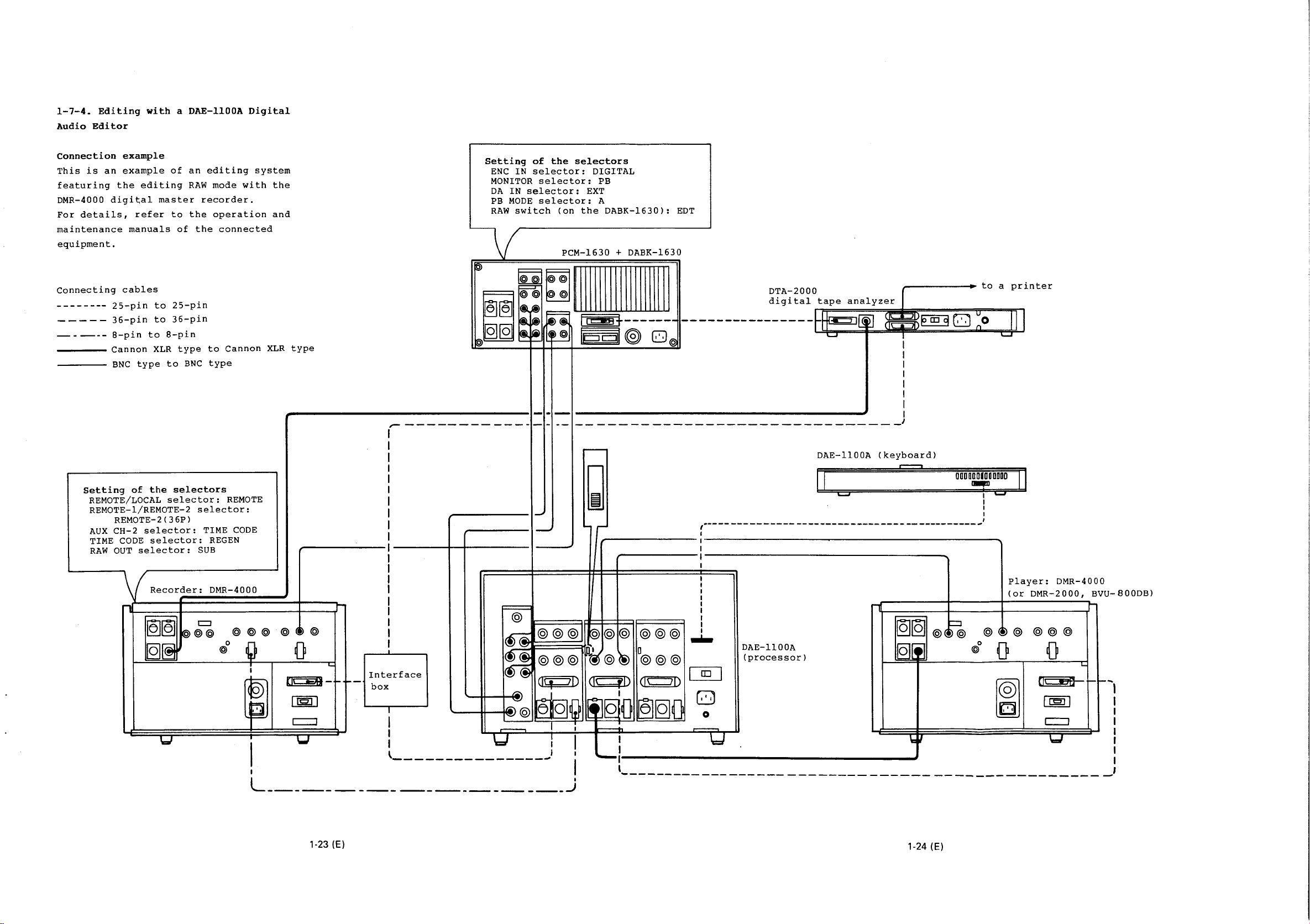
1-7-4.
Audio
Editing
Editor
with a DAE-llOOA
Digital
Connection
This
is
an
featuring
DMR-4000
For
details,
maintenance
equipment.
Connecting
------
----
----
----
----
example
example
the
editing
digi~al
refer
manuals
cables
25-pin
36-pin
8-pin
Cannon
BNC
to
to
to
XLR
type
of
master
to
of
25-pin
36-pin
8-pin
type
to
an
RAW
recorder.
the
the
BNC
editing
mode
operation
connected
to
Cannon
type
system
with
the
and
XLR
type
-------------------1-
,.-----------------
Setting
ENC
MONITOR
DA
PB
RAW
~
~~~~~~~~m~~III
@00
of
the
IN
selector:
selector:
IN
selector:
MODE
selector:
switch
~~r~
selectors
DIGITAL
EXT
(on
the
PCM-1630
lt=JCJ''
PB
A
DABK-1630):
+ DABK-1630
®
0@
·-
-----------------------------~
-
EDT
~---------.to
___________
!!~~~~~'~:;~~'Y'"'
EE'-J§iDII
~
0
~~[§~C
I
I
I
I
I
I
a
printer
~
0
11
........
E
I
DAE-llOOA
(keyboard)
Setting
REMOTE/LOCAL
REMOTE-1/REMOTE-2
AUX
TIME
RAW
of
the
selector:
REMOTE-2(36P)
CH-2
selector:
CODE
OUT
selector:
selector:
Recorder:
selectors
selector:
TIME
SUB
REMOTE
CODE
REGEN
DMR-4000
@@@
Q
L
,------------1~
,--------
Cl¢¥1&--
Interface
-
box
I
I
I
I
t I
---------------~
___________________
,.----,
'd
I
___,J
@
©©©I@©©©©©
@@@
CI%JD Clc=yD <lc::::m
I I
e
oiQ
:
r
~-------------~--------------------~------------------------~
r------,----------------------------------~
p~
~~@@
~~810
I
~~--------------------------------------------__J
I
j
I I
-------------------------------------------------
r--------------------------------------------·
I
I
I
I
I
I
I
I
I
I
I
I
[]
@@@
~§G
--
0
'tc::J
DAE-1100A
(processor)
II
...,
1§119
fQJl!]
@~~
\:I
OOOOOOIOODOOD
-r
lc:::J
I
I
I
I
@
0
@
Pla
(or
(~@
0
I
.
yer:
DMR-2000,
@@@
0
DMR-4000
BVU-800DB)
..
,
I
I
I
I
I
I
I
1-23 (E)
1-24 (E)

1-7-5.
Four-channel
possible
PCM-1630s.
Make
between
(connections
the
the
Synchronization
connections
each
two
PCM-1630s
COMPOSITE
using
recording
two
for
recorder
G)
to
with
SYNC
with
and
recorders
recording
and
®).
each
OUTPUT
Two
PCM-1630s
playback
and
and
PCM-1630
To
synchronize
other,
connector
is
two
playback
pair
connect
of
one
PCM-1630
connector
For
synchronized
code
on
on
both
If
the
two
precisely
synchronizer
required
~).
to
the
of
the
audio
recorders.
channel-2
recorders
in
frame
or a DAE-1100
in
the
COMPOSITE
other
playback,
system
(connection®)
must
units
(connections
SYNC
record
track
be
during
editor
INPUT
the
of
the
tape
synchronized
playback,
is
~
•
time
a
to
r1\
\V
G)
Audio
Audio
input
output
signals
signals
{
{
CH-1
CH-2
CH-1
CH-2
..
::
...
•
~.
Setting
ENC
DA
IN
PB
PCM-1630
~
@
~~
~~~
@ @
@ @
@
@
@
(master)
@@
=
l<f)
\_..
I(!)
I~~
@
@
@
II
c::::J
II
~~~I@
MODE
u u
r
.,,
G)-,,
l I
p
""
'~
~@
l'::::=:
c.,.
u
BVU-800DA/DB
(or
DMR-2000/4000)
G)l
Protector
/_
,
= = =
@
@ @
0 0
@ @
@
~
===
~03~~
===
~=~
0
El
4
'
@
~I§§
[QQJ
[J
TI
;;EJ
G
LJ
Time
r-
IN
v
0
code
...
,
....
.....
of
selector:
selector:
the
selectors
ANALOG
INT
selector~
®
0
®
Time
code
@l
Synchronizer
G
A
Audio
Audio
..
..
~.
©
or
DAE-1100
input
output
@
0
.,
@
signals
{ CH-3
CH-4
signals
{CH-3
CH-4
..
...
..
...
...
~
~
Time
PCM-1630
!®@
~~
~~~
~
.
code
r1
c.,.
..
..
.,
L'::=
u
(slave)
-@@
=
@@
@@
@@
@@
@@
'
I~@
i(j)
@
®
(j)
.,,
Protector
=
·=
@ @ @
~
BVU-800DA/DB
(or
@ @
===
~03~~
§§§
§5§:§5
===
DMR-2000/4000)
Setting
ENC
DA
PB
II
c::::J
I I
t~~t@
®
~
~
/
/
Jl
0 0
=
@
~
~
0
@ 4
§§
IC
0
G'
Jl
fD
I'D
LJ
IN
IN
selector:
MODE
v
0
u
r-
'r-
of
the
selector:
selector:
0
selectors
ANALOG
INT
A
1-25 (E)
1-26 (E)
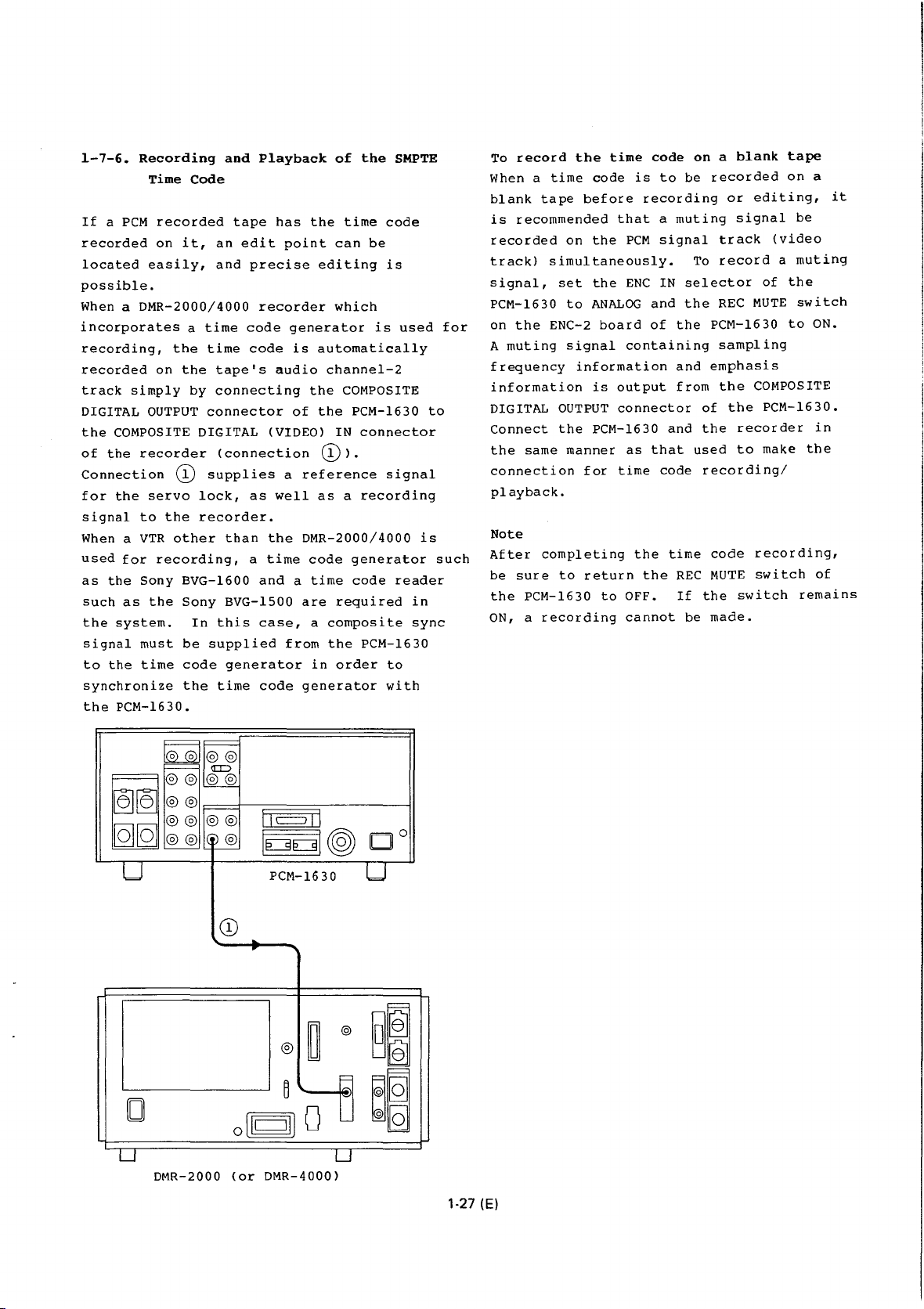
1-7-6.
If a PCM
recorded
located
possible.
When a
incorporates
recording,
recorded
track
DIGITAL
the
of
Connection
for
signal
When a
used
as
such
the
signal
to
synchronize
the
Recording
Time
recorded
on
easily,
DMR-2000/4000
the
on
simply
OUTPUT
COMPOSITE DIGITAL (VIDEO)
the
recorder
(!)
the
servo
to
the
VTR
other
for
recording,
the
Sony
as
the
system.
must
the
time
PCM-1630.
and
Code
tape
it,
an
and
a
time
time
the
tape's
by
connecting
connector
(connection
supplies
lock,
recorder.
than
BVG-1600
Sony
BVG-1500
In
this
be
supplied
code
generator
the
time
edit
code
Playback
has
the
point
precise
recorder
generator
code
is
audio
the
of
a
reference
as
well
the
DMR-2000/4000
a
time
code
and a time
are
case,
code
a
from
in
generator
of
the
SMPTE
time
code
can
be
editing
which
automatically
channel-2
the
IN
is
is
used
COMPOSITE
PCM-1630
connector
(!) ) .
signal
as a recording
generator
code
reader
required
composite
the
PCM-1630
order
to
with
to
is
in
sync
for
such
To
record
When a
blank
is
recorded
track)
signal,
PCM-1630
on
A
frequency
information
DIGITAL
Connect
the
connection
playback.
Note
After
be
the
ON, a
time
tape
recommended
simultaneously.
the
ENC-2
muting
same
completing
sure
PCM-1630
recording
the
code
before
on
the
set
the
to
ANALOG
board
signal
information
is
OUTPUT
the
PCM-1630
manner
for
to
return
to
time
code
is
recording
that
PCM
ENC
and
of
containing
output
connector
as
that
time
the
the
OFF.
cannot
on a blank
to
be
a
muting
signal
To
IN
selector
the
the
and
from
and
code
time
REC
If
be
recorded
or
signal
track
record
REC
PCM-1630
sampling
emphasis
the
of
the
the
recorder
used
to
recording/
code
MUTE
the
switch
made.
tape
on
a
editing,
be
(video
a
muting
of
the
MUTE
switch
to
ON.
COMPOSITE
PCM-1630.
in
make
the
recording,
switch
of
remains
it
~
~~
=®®®®
u
~
®®®® ®®
®®lb
II
c:::::J
[E:9E:9[@)
PCM-1630
CD
®
0
o
B
[lc:::=:JI]
-u
DMR-2000
(or
DMR-4000)
I I
Do
u
@
~
0 @
§~
TI
~~
u
[Q]
1-27 (E)
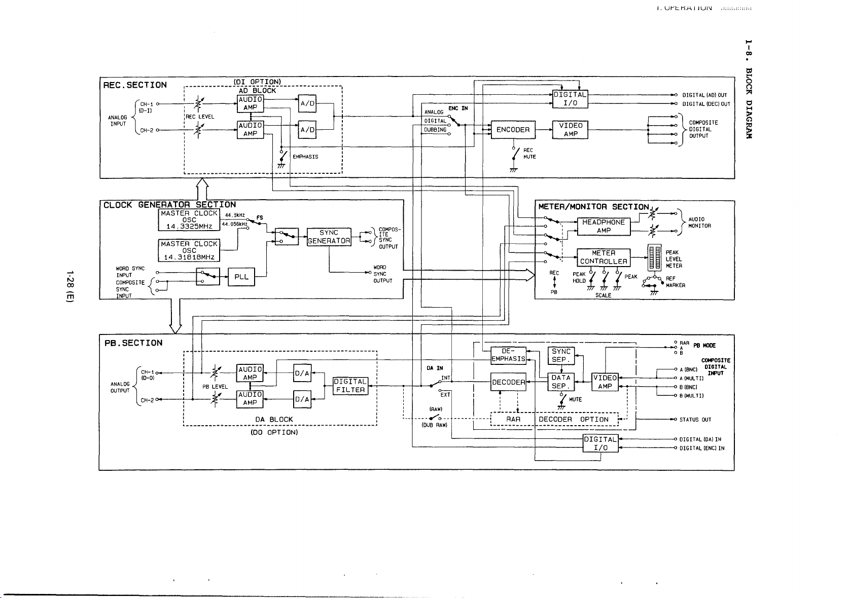
REC.
ANALOG
INPUT
SECTION
g~~t
{
CH-2 :
(OI OPTION)
: t
:REC
LEVEL
:1/
:
rr-
I
___
.j
A/D
A/D
ANALOG
DIGITAL'\
DUBBING
ENC
IN
: j ! I I
L
_____________________
f--E:~:~~I:
______
i
II
I
~ENCODER
I
Jl~
,.1.
MUTE
~
lDIGITALf
I/0
V~OEO
AMP
I.
Ut-'t:.tif-\
IIUI\l
DIGITAL
(AD)
DIGITAL
(DEC)
}COMPOSITE
DIGITAL
OUTPUT
,1,;,:.1::::111
OUT
OUT
,_.
I
co
ttl
5
(')
:>'1
0
H
~
~
,.:.,
co
m
CLOCK
GENERATOR
WORD
SYNC
INPUT
COMPOSITE
SYNC
INPUT
{
PB.SECTION
CH-I
ANALOG
OUTPUT
(D-Ol
{
CH-2 !
J
SE~C~T~I~O~N--------------------------~
MASTER CLOCK
14.
3o;2c5MHz
MASTER CLOCK
osc
14.3181BMHZ
!
T
_L
1
I t
:
:
:
~-
o--1
PB
-
LEVEL
:V_
rr-
44.!kHz
44.055kHz
FS
PLL
AUDIO
AMP
AUDIO~
AMP
DA
BLOCK
(DO
OPTION)
GENERATOR
ID/A
SYNC
I
L.______.,
COMPOSITE
>
SYNC
}
OUTPUT
WORD
SYNC
OUTPUT
I
:
:
DA
IN
!NT
n
,------'----+-<-oo
: I 8
! I 1 :
(RAW)
--· ----
...-'e>--
(DUB
L-------------~-----I__;~Q__}o-----------o
-----Li=:_~-
RAW)
: :
.-~----t
I
I I '
'f
MUTE
___
i!r
---------------------·
=~~~~-~:
DIGITAl
1
:
:JI
f-----•o
-------o
~0
LEVEL
METER
REF
MARKER
~AR
o B
A
A
B (MULTI)
STATUS
DIGITAL
DIGITAL
PB
MODE
COMPOSITE
(BNC)
O~~~~L
(MUL
Til
(8NC)
OUT
(OA)
(ENC)
IN
IN
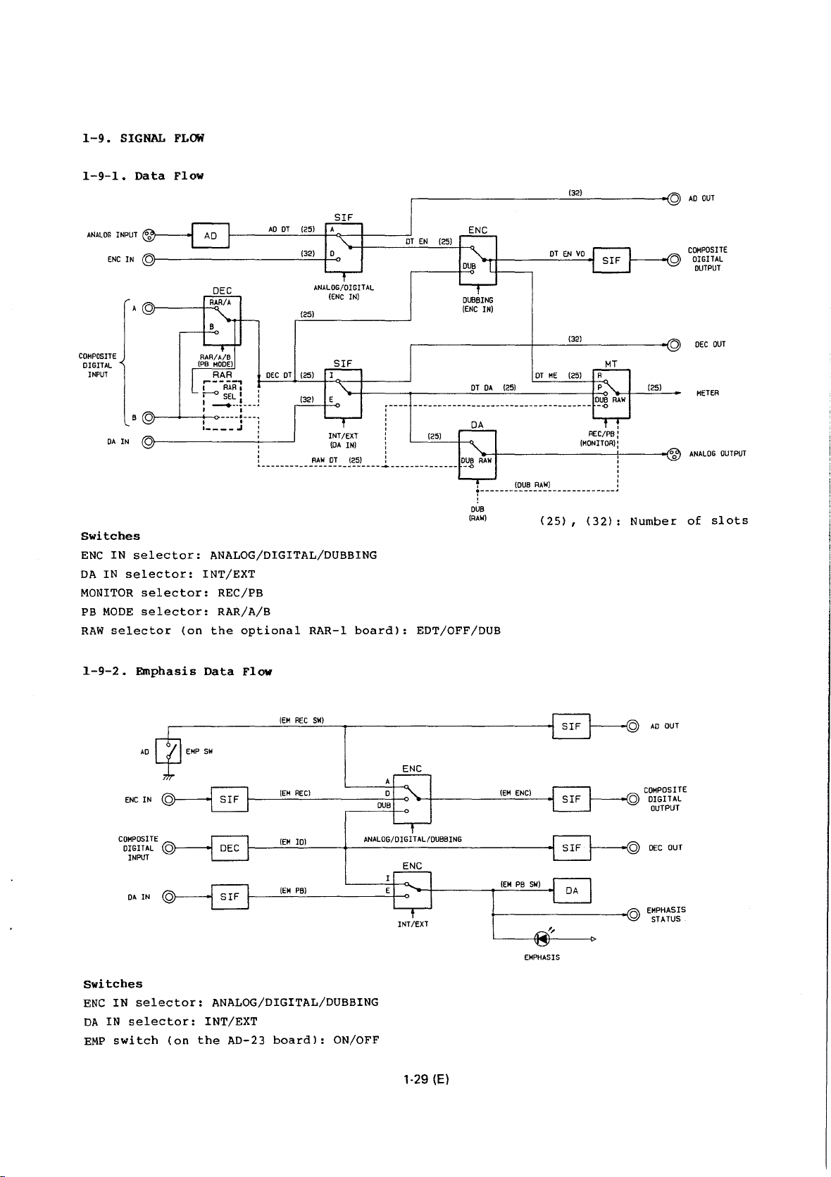
1-9.
SIGNAL
FLOW
1-9-1.
ANALOG
INPUT
ENC
COMPOSITE
DIGITAL
INPUT
Switches
ENC
IN
DA
IN
MONITOR
PB
MODE
RAW
selector
Data
IN
selector::
selector::
selector:
selector:
Flow
AD
DT
DEC
ANALOG/DIGITAL/DUBBING
!NT/EXT
REC/PB
RAR/A/B
(on
the
optional
(25)
(32)
ANALOG/DIGITAL
(ENC
(25)
RAR-1
IN)
board):
-+----------+:----{
,
;-
-------------------------
DUB
(RAW)
EDT/OFF/DUB
(OUB
RAW)
(25),
REC/PB:
(MONITOR):
__
(32):
'
'
'
'
:
..
Number:
0
0
COMPOSITE
DIGITAL
OUTPUT
METER
ANALOG
of
slots
OUTPUT
1-9-2.
COMPOSITE
DIGITAL
Switches
ENC
IN
DA
IN
EMP
switch
Emphasis
AD
ENC
IN
INPUT
DA
IN
selector:
selector::
(on
Data
Flow
(EM
REC
SW)
EMP
SW
(EM
RECl
(EM
IQ)
(EM
PB)
ANALOG/DIGITAL/DUBBING
!NT/EXT
the
AD-23
board):
ANALOG/0
ON/OFF
ENC
IGIT
AL
/DUBBING
ENG
INT /EXT
1-29 (E)
(EM
(EM
ENC)
PB
SW)
EMPHASIS
,,
AO
OUT
COMPOSITE
DIGITAL
OUTPUT
EMPHASIS
STATUS
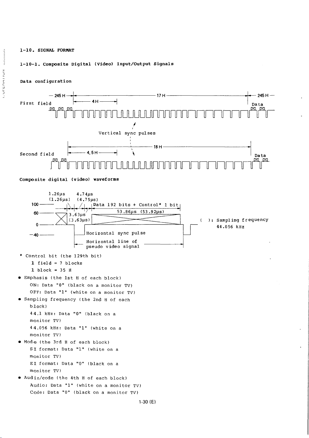
1-10.
SIGNAL
FORMAT
1-10-1.
7
5
t
[
~
)
Data
First
Composite
configuration
-245
field
Digital
H - ..
.f..,
:.-------------17
14·
---
(Video)
4 H
---·1
Input/Output
Signals
H
------------t--
245
Data
H-
I
Second
field
I:
Vertical
4.5H
·'
sync
pulses
18
H
Data
'
Composite
digital
(video)
waveforms
192
bits
+
Control*
1
-40--
*
Control
1
1
•
Emphasis
ON:
OFF:
Sampling
•
block)
44.1
monitor
44.056
monitor
•
Mode
SI
monitor
EI
monitor
•
Audio/code
Audio:
Code:
field
block
Data
Data
kHz:
(the
format:
format:
Data
bit
(the
7
35
(the
1st H of
"0"
"1"
frequency
Data
TV)
kHz:
TV)
3rd H of
Data
TV)
Data
TV)
(the
Data
"0"
!29th
blocks
H
(black
(white
"0"
Data
"1"
"0"
4th H of
"1"
(black
Horizontal
pseudo
bit)
each
on a monitor
on a monitor
(the
2nd H of
(black
"1"
(white
each
block)
(white
(black
(white
on a monitor
sync
line
video
block)
each
on
a
on
a
on
a
on
a
each
block)
on a monitor
pulse
of
signal
TV)
TVI
TV)
TV)
):
Sampling
44.056
frequency
kHz
1-30 (E)

1-10-2.
Digital
Input/Output
and
Control
Signals
Word
CH-1
CH-2
Digital
sync
data
data
input/output
i-------------(44.056kHz)-------------~
M
s
B
format
22.676
(44.1
22.698
lJS
kHz)
lJS
I I
i n
U U
I
I
!when
bit
I
:When
i
bit
is
is
the
the
29th
0
29th
1
Wor
Bit
d
255
256
257
258
1
2
3
.
.
.
.
.
1 2
3 4 5 6 7
8 9
Block
PCM
data
10
11
12
13
PCM
data
configuration
14
15
16
17
18 19
20
Control
user's
21
22
23
Control
User's
bits
bits
24 25
Block
26
bits
bits
27
or
28 29
flag
1
0
0
0
0
1
0
!Sync
:area
I
bit
.-i
co
c::
!j\
.
.....
tJl
u
c::
:>.
Ul
information
Control
block
are
every
flag
attached
256
bits
and
bit
words.
"1"
1-31
(E)

Control
signal
block
structure
PCM
data
Control
bits
1 2 3 4 5 6 7 8 9
* When
**
***
the
block
audio/non-audio
dubbing
identification
In
bit
For
between
10601
serial
bit
signal
bit
identification
the
is
interface
is
is
26th
prohibition
PCM-1630,
always
the
and
No.
used
bit.
used
bit
0:
Normal
1:
Automatic
higher
11301
10
11
12
flag
bit
identification
bit
bits
are
the
dubbing
"0".
(signal:
DAE-llOOA
and
the
and
higher,
independently
Therefore,
as
the
emphasis
bit.
editing
13 14
Dubbing
is
and
also
DA
with
only
15 16
17 18 19
prohibition
0:
Dubbing
1:
Dubbing
"0",
the
bit,
emphasis
"0".
prohibition
IN
CH-1)
serial
PCM-1630
the
as
the
the
No.
with
26th
EDIT
27th
20
21
22 23 24 25 26
is
possible.
is
prohibited.
bit**
27
28 29
~Sync
Block
every
Audio/non-audio
0:
1:
Emphasis
00:
Emphasis
01:
Emphasis
(50
I I
information
flag
bit
256
words*.
Audio
Non-audio
identification
is
is
rsec.,
15
"1"
identification
bits***
not
used.
used.
rsec.)
area
is
attached
bit
1·32 (E)
 Loading...