

Sony MEX-V30 Schematic
MEX-V30
SERVICE MANUAL
Ver. 1.1 2011.08
SPECIFICATIONS
Monitor section
Display type: Wide LCD color monitor
Dimensions: 3.0 in
System: TFT active matrix
Number of pixels:
76,800 pixels (320 × 240)
Color system:
PAL/NTSC/automatic select
Tuner section
FM
Tuning range: 87.5 – 107.9 MHz
Antenna (aerial) terminal:
External antenna (aerial) connector
Intermediate frequency: 150 kHz
Usable sensitivity: 12 dBf
Selectivity: 20 dB at 400 kHz
Signal-to-noise ratio: 55 dB (mono)
Separation: 30 dB at 1 kHz
Frequency response: 20 – 15,000 Hz
AM
Tuning range: 530 – 1,710 kHz
Antenna (aerial) terminal:
External antenna (aerial) connector
Intermediate frequency: 450 kHz
Sensitivity: 26 μV
DVD/CD Player section
Signal-to-noise ratio: 120 dB
Frequency response: 20 – 20,000 Hz
Wow and flutter: Below measurable limit
Harmonic distortion: 0.03 %
Region code: Labeled on the bottom of the unit
USB Player section
Interface: USB (Full-speed)
Maximum current: 500 mA
Power amplifier section
Outputs: Speaker outputs
Speaker impeda nce: 4 – 8 ohms
Potência de saída
26 W RMS x4 - 4 ohms, 1 kHz, 10 % THD*, 14,4 V
* medição com um canal ativo
Brazilian Model
Model Name Using Similar Mechanism NEW
Mechanism Type DL-C28DB2-YG2
General
Outputs:
Video output terminal (rear)
Audio output terminals (front)
Audio output terminals (rea r/sub)
Power antenna (aerial) relay control terminal
Power amplifier control terminal
Inputs:
Antenna (aerial) input te rminal
Parking break control terminal
Camera input terminal
AUX audio input terminals (front/rear)
AUX video input terminal
USB signal input c
Power requirements: 12 V DC car battery
(negative ground (earth))
Dimensions: Approx. 178 u 50 u 191.5 mm (w/h/d)
Mounting dimensions: Approx. 182 u 53 u 165 mm
(w/h/d)
Mass: Approx. 1.7 kg
Supplied accessories:
Remote Commander: RM-X171
Parts for installation and connections (1 set)
Your dealer may not handle some of the above listed
accessories. Please ask the de aler for detailed
information.
Design and specifications are subject to cha nge
without notice.
Weights and dimensions are approximate.
Region code
The region system is used to protect software
copyrights.
The region code is located on the bottom of the unit,
and only DVDs labeled with an ident ical region code
can be played on this u nit.
DVDs labeled can also be played.
If you try to play any other DVD, the message
“Playback prohibited by region code.” will appear on
the monitor screen. Depending on the DVD, no region
code may be labeled even though playing the DVD
prohibited by area restrictions.
onnector
ALL
is
9-893-245-02
2011H33-1
2011.08
©
MULTIMEDIA AV RECEIVER
Sony Corporation
Published by Sony Techno Create Corporation
MEX-V30
SECTION 1
SERVICING NOTES
Manufactured under lice nse
from Dolby Laboratories.
symbol are trademarks of Dolby Laboratories.
Windows Media is either a registered trademark or
trademark of Microsoft Corporation in the United
States and/or other countries.
This product contains technolog y subject to certain
intellectual property rights of Microsoft. Use or
distribution of this technology out side of this
product is prohibited without the appropriate
license
US and foreign patents licensed from Dolby
Laboratories.
MPEG Layer-3 audio coding technology and
patents licensed from F raunhofer IIS and Thomson.
“DVD VIDEO,” “DVD-R,” “DVD-RW,” “DVD+R,”
and “DVD+RW” are trademarks.
This product uses font data which is licensed to
Sony by Monotype Imaging Inc. or its affiliates.
THIS PRODUCT IS LICENSED UNDER THE
MPEG-4 VISUAL PATENT PORTFOLIO
LICENSE FOR THE PERSONAL AND NONCOMMERCIAL USE OF A CONSUMER FOR
DECODING MPEG-4 VIDEO
ENCODED BY A CONSUMER ENGAGED IN A
PERSONAL AND NON-COMMERCIAL
ACTIVITY AND/OR WAS OBTAINED FROM A
VIDEO PROVIDER LICENSED BY MPEG LA
TO PROVIDE MPEG-4 VIDEO. NO LICENSE IS
GRANTED OR SHALL BE IMPLIED FOR ANY
OTHER USE. ADDITIONAL INFORMATION
INCLUDING THAT RELATING TO
PROMOTIONAL, INTERNAL AND
COMMERCIAL USES AND LICENSING MAY
BE OBTAINED FROM MPEG LA, LLC. SEE
HTTP://WWW.MPEGLA.COM
All other trademarks are trademarks of their
respective owners.
“Dolby” and the double-D
(s) from Microsoft.
THAT WAS
FLEXIBLE CIRCUIT BOARD REPAIRING
• Keep the temperature of soldering iron around 270 °C during
repairing.
• Do not touch the soldering iron on the same conductor of the
circuit board (within 3 times).
• Be careful not to apply force on the conductor when soldering
or unsoldering.
NOTES ON HANDLING THE OPTICAL PICK-UP
BLOCK OR BASE UNIT
The laser diode in the optical pick-up block may suffer electrostatic break-down because of the potential difference generated by
the charged electrostatic load, etc. on clothing and the human body.
During repair, pay attention to electrostatic break-down and also
use the procedure in the printed matter which is included in the
repair parts.
The fl exible board is easily damaged and should be handled with
care.
NOTE ON LASER DIODE EMISSION CHECK
The laser beam on this model is concentrated so as to be focused
on the disc refl ective surface by the objective lens in tha optical
pick-up block. Therefore, when checking the laser diode emission,
observe from more than 30 cm away from the objective lens.
NOTE FOR THE 28-PIN CONNECTOR
Do not use alcohol to clean the 28-pin connector connecting the
front panel with the main body.
Do not touch the connector directly with your bare hand. Poor contact may be caused.
Main unit
Back of the front
panel
ABOUT THE REPAIRING OF BOARD
When electric parts installed by this unit are defective, replace the
complete mouted board. Individual electrical parts that the mount
is done cannot be exchanged.
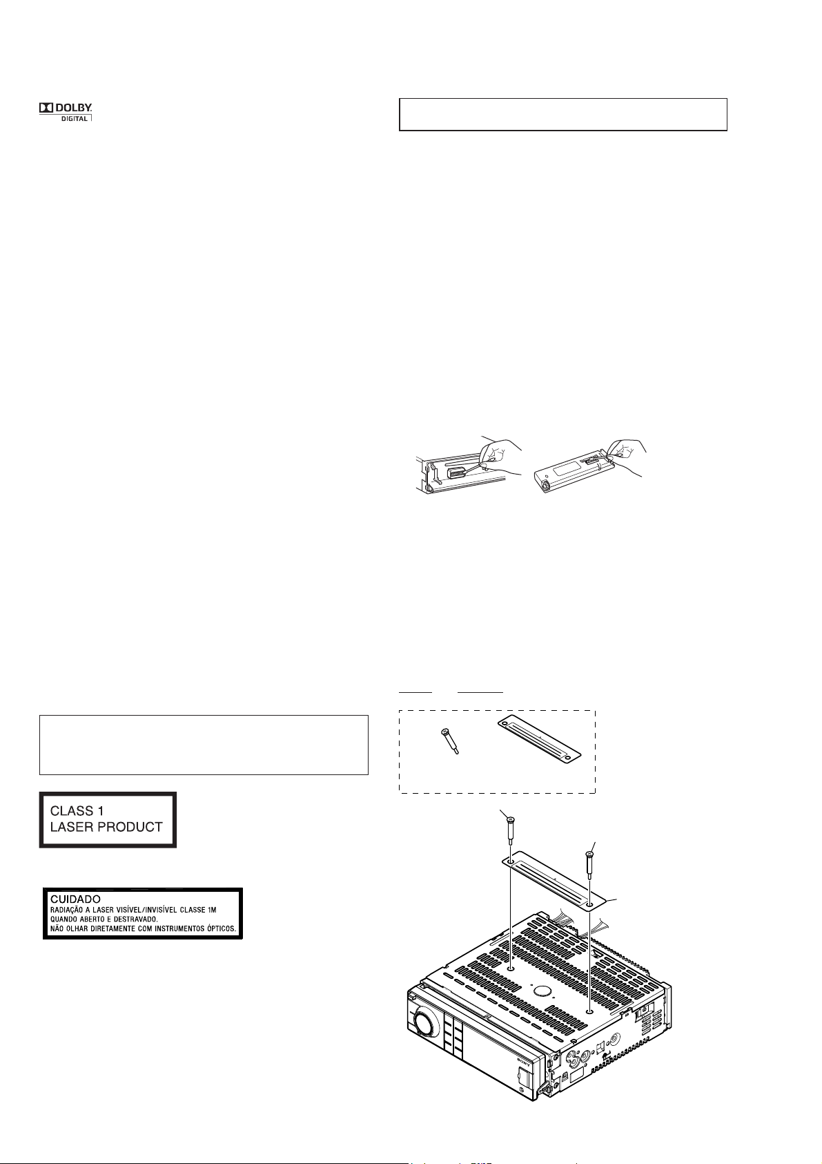
NOTE FOR TRANSPORTATION
When this unit is transported, it is necessary to install two transportation screws. Please transport it after installing two transportation
screws as shown in the fi gure below.
Part No. Description
A-1844-216-A SCREW WITH WARNING LABEL
CAUTION
Use of controls or adjustments or performance of procedures
other than those specifi ed herein may result in hazardous radia-
tion exposure.
This label is located on the bottom of the
chassis.
This label is located on the drive unit’s internal
chassis.
SAFETY-RELATED COMPONENT WARNING!
COMPONENTS IDENTIFIED BY MARK 0 OR DOTTED LINE
WITH MARK 0 ON THE SCHEMATIC DIAGRAMS AND IN
THE PARTS LIST ARE CRITICAL TO SAFE OPERATION.
REPLACE THESE COMPONENTS WITH SONY PARTS
WHOSE PART NUMBERS APPEAR AS SHOWN IN THIS
MANUAL OR IN SUPPLEMENTS PUBLISHED BY SONY.
Transportation screw
u2
transportation screw
ATENCAO!!!
Warning label
u1
ATENCAO!!!
transportation screw
warning label
2
SECTION 2
GENERAL
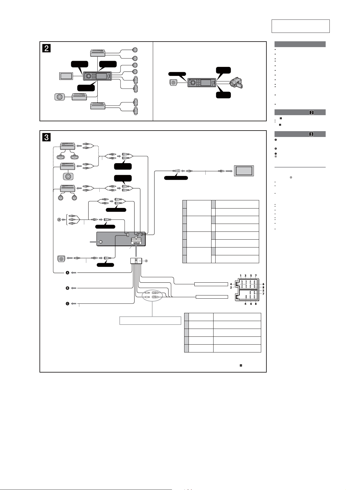
AB
FRONT
AUDIO OUT
2
*
2
*
AUX AUDIO IN
AUX VIDEO IN
CAMERA IN
REAR/SUB
AUDIO OUT
FRONT
AUDIO OUT
Fuse (10 A)
Blue/white stripedAMP REM
Purple/white striped
CAMERA IN
REAR VIDEO OUT
1
2 – Speaker, rear, right
3
4 – Speaker, front, right
5
6 – Speaker, front, left
7
8 – Speaker, rear, left
Negative polarity positions 2, 4, 6, and 8 have striped leads.
AUX
AUDIO IN
AUX
VIDEO IN
2
*
+ Speaker, rear, right
Purple
+ Speaker, front, right
Gray
+ Speaker, front, left
White
+ Speaker, rear, left
Green
From the car’s speaker connector
Max. supply current: 0.3 A
REAR
VIDEO OUT
REAR/SUB
AUDIO OUT
2
*
From car antenna (aerial)
REVERSE IN
2
*
Video camera*
*not supplied
MEX-V30
This section is extracted
from instruction manual.
Cautions
Run all ground (earth) leads to a common ground
(earth) point.
is unit is designed for negative ground (earth) 12 V
DC operation only.
Do not disassemble or modify the unit.
Do not install in locations which interfere with airbag
operation.
Do not get the leads under a screw, or caught in moving
parts (e.g. seat railing).
Before making connections, turn the car ignition off to
avoid short circuits.
Connect the yellow and red power supply leads only
after all other leads have been connected.
Be sure to insulate any loose unconnected leads with
electrical tape for safety.
Do not press on the LCD when installing the unit.
Install the unit with the monitor facing straight forward;
do not install it at a slanted angle.
Notes on the power supply lead (yellow)
When connecting this unit in combination with other
stereo components, the amperage rating of the car
circuit to which the unit is connected must be higher
than the sum of each component's fuse amperage rating.
If no car circuits are rated high enough, connect the unit
directly to the battery.
Connection example
Notes ( -A)
Be sure to connect the ground (earth) lead before connecting the amplier.
The alarm will only sound if the built-in amplier is used.
Note ( -B)
You cannot use multiple auxiliary devices simultaneously, even if they are
connected to dierent terminals.
Connection diagram
To AMP REMOTE IN of an optional power
amplier
This connection is only for ampliers. Connecting any other system
may damage the unit.
To the car's reverse lamp cord for an optional rear
view camera
To the parking brake switch cord
To an auxiliary device such as a portable media
player, game console, etc. (not supplied)
Tip
You can use an RCA cord (not supplied) to connect auxiliary devices.
Warning
If you have a power antenna (aerial) without a relay box,
connecting this unit with the supplied power supply
connection cable
Notes on the control and power supply leads
Memory hold connection
When the yellow power supply lead is connected, power will always be
supplied to the memory circuit even when the ignition switch is turned o.
Notes on speaker connection
may damage the antenna (aerial).
The power antenna (aerial) control lead (blue) supplies +12 V DC when
you turn on the tuner.
If your car has a built-in FM/AM antenna (aerial) in the rear/side glass,
connect the power antenna (aerial) control lead (blue) or the accessory
power supply lead (red) to the power terminal of the antenna (aerial)
booster. For details, consult your car dealer.
A power antenna (aerial) without a relay box cannot be used with this unit.
Before connecting the speakers, turn the unit o.
Use speakers with an impedance of 4 to 8 ohms, and with adequate
power handling capacities to avoid damage.
Do not connect the speaker terminals to the car chassis, or connect the
terminals of the right speakers with those of the left speakers.
Do not connect the ground (earth) lead of this unit to the negative (–)
terminal of a speaker.
Do not attempt to connect the speakers in parallel.
Connect only passive speakers. Connecting active speakers (with
built-in ampliers) to the speaker terminals may damage the unit.
To avoid a malfunction, do not use the built-in speaker leads installed in
your car if they feature a common negative (
speakers.
Do not connect the unit’s speaker leads to each other.
–
) lead for the right and left
PARKING BRAKE
1
*
Light green
For details, see “Power connection diagram” on the reverse side.
From the car’s power connector
4 Yellow Continuous power supply
5 Blue Power antenna (aerial) control
6 Orange Switched illumination power supply
7 Red Switched power supply
8 Black Ground (earth)
Positions 1, 2, and 3 do not have pins.
*1 For details on connecting to the parking brake switch cord, see
“Connecting the parking brake lead (
2
*
RCA pin cord (not supplied)
)” on the reverse side.
3
 Loading...