

Sony MEX-1-HD Service manual
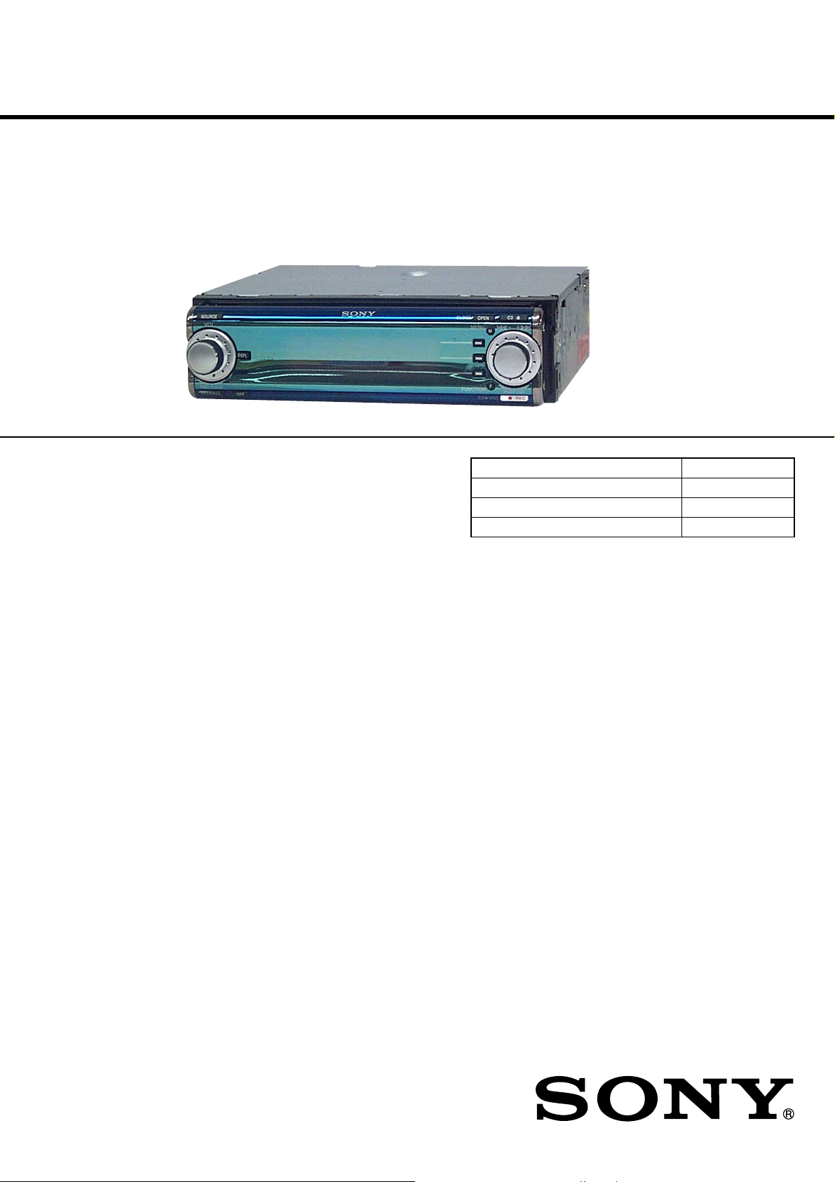
MEX-1HD
SERVICE MANUAL
Ver 1.3 2004.02
SPECIFICATIONS
AUDIO POWER SPECIFICATIONS
(US model only)
POWER OUTPUT AND TOTAL HARMONIC DISTORTION
23 watts per channel minimum continuous average power into 4 ohms,
4 channels driven from 20 Hz to 20 kHz with no more than 5% total
harmonic distortion.
CD Player section
Signal-to-noise ratio 90 dB
Frequency response 10 – 20,000 Hz
“MG Memory Stick” section
Signal-to-noise ratio 90 dB
Frequency response 10 – 20,000 Hz
Recording time (when using the supplied 64MB
“MagicGate Memory Stick”)
Recording format Adaptive Transform
HDD section
Capacity 10 GB
Recording format Adaptive Transform
Frequency response 20 to 20,000 Hz
Tuner section
FM
Tuning range 87.5 – 107.9 MHz
Antenna terminal External antenna connector
Intermediate frequency 10.7 MHz/450 kHz
Usable sensitivity 8 dBf
Selectivity 75 dB at 400 kHz
Signal-to-noise ratio 66 dB (stereo),
Approx. 60 min. (132kbps)
Approx. 80 min. (105kbps)
Acoustic Coding 3
(ATRAC3)
Acoustic Coding 3
(ATRAC3)
(single signal measurement)
72 dB (mono)
Harmonic distortion at 1 kHz
Separation 35 dB at 1 kHz
Frequency response 30 – 15,000 Hz
AM
Tuning range 530 – 1,710 kHz
Antenna terminal External antenna connector
Intermediate frequency 10.7 MHz/450 kHz
Sensitivity 30 µV
Power amplifier secti on
Outputs Speaker outputs
Speaker impedance 4 – 8 ohms
Maximum power output 52 W × 4 (at 4 ohms)
General
Outputs Audio outputs (front/rear)
Inputs Telephone ATT control
US Model
Canadian Model
Australian Model
Model Name Using Similar Mechanism NEW
CD Drive Mechanism Type MG-550D-156
Optical Block Name CDM-3021EBG
Optical Pick-up Name DAX-21EG
0.6 % (stereo),
0.3 % (mono)
(sure seal connectors)
Subwoofer output (mono)
Power antenna relay control
terminal
Power amplifier control
terminal
terminal
Illumination control
terminal
AUX IN terminal
Antenna input terminal
Tone c ontrols Bass ±8 dB at 100 Hz
Loudness +8 dB at 100 Hz
Power requirements 12 V DC car battery
Dimensions
Mounting dimensions
Mass Approx. 2.0 kg
Supplied accessories Parts for installation and
Note
This unit cannot be connected to a digital preamplifier
or an equalizer.
Design and specifications are subject to change
without notice.
Treble ±8 dB at 10 kHz
+2 dB at 10 kHz
(negative ground)
Approx. 178 × 50 × 182 mm
(7 1/8 × 2 × 7 1/4 in.)
(w/h/d)
Approx. 182 × 53 × 161 mm
1
(7
/4 × 2 1/8 × 6 3/8 in.)
(w/h/d)
(4 lb. 7 oz.)
connections (1 set)
Front panel case (1)
Cleaning cloth (1)
Digital I/O cable (1)
E Model
9-873-923-04 Sony Corporation
2004B05-1 e Vehicle Company
© 2004.02 Published by Sony Engineering Corporation
AUDIO LIBRARY SYSTEM

MEX-1HD
Ver 1.1
TABLE OF CONTENTS
1. SERVICING NOTES ................................................ 5
2. GENERAL
Location of Controls ....................................................... 7
3. DISASSEMBLY
3-1. Disassembly Flow ........................................................... 10
3-2. Cover ............................................................................... 11
3-3. Base Panel Assy .............................................................. 11
3-4. Sub Panel (CD) Assy ...................................................... 12
3-5. Mechanism Deck (MG-550D-156) ................................ 12
3-6. Motor Block Assy, Cam Block Assy .............................. 13
3-7. Motor Assy (Front Panel Open/Close) (M601),
SWITCH Board............................................................... 13
3-8. MAIN Board, POWER Board ........................................ 14
3-9. Hard Disk Drive (2.5 inch) Unit..................................... 15
3-10. SUB Board ...................................................................... 15
3-11. Heat Sink, DC Fan (M501) ............................................. 16
3-12. Belt (L), LE Motor Assy (Tray Open/Close) (M103).... 16
3-13. Tray (UD) Assy ............................................................... 17
3-14. OP Assy (CDM-3021EBG) ............................................ 17
3-15. SERVO Board ................................................................. 18
4. ASSEMBLY
4-1. Assembly Flow ................................................................ 19
4-2. Motor Block Assy ........................................................... 19
4-3. Cam Block Assy .............................................................. 20
4-4. Phase Alignment of Motor Block Assy and
Cam Block Assy.............................................................. 20
6-28. Printed Wiring Board
– SUB Board (Conductor Side) – ................................... 55
6-29. Printed Wiring Board – POWER Board –..................... 56
6-30. Schematic Diagram – POWER Board – ........................ 57
6-31. Printed Wiring Board – DISPLAY Board – .................. 58
6-32. Schematic Diagram – DISPLAY Board – ..................... 59
6-33. IC Pin Function Description ........................................... 69
7. EXPLODED VIEWS
7-1. Cover Section................................................................. 97
7-2. Front Panel Section ........................................................ 98
7-3. ARM Section.................................................................. 99
7-4. Hard Disk, POWER Board Section...............................100
7-5. MAIN Board Section ..................................................... 101
7-6. Chassis Section ..............................................................102
7-7. SUB Board Section ........................................................103
7-8. Mechanism Deck Section (MG-550D-156) .................. 104
8. ELECTRICAL PARTS LIST ..............................106
5. TEST MODE.............................................................. 21
6. DIAGRAMS
6-1. Block Diagram
– SERVO, HD/MS/USB INTERFACE Section – .......... 27
6-2. Block Diagram – CPU, DISPLAY Section – ................ 28
6-3. Block Diagram – AUDIO, SYSTEM Section – ............ 29
6-4. Block Diagram – POWER SUPPLY Section –............. 30
6-5. Note for Printed Wiring Boards and
Schematic Diagrams ....................................................... 31
6-6. Printed Wiring Board – SERVO Board (Side A) – ....... 32
6-7. Printed Wiring Board – SERVO Board (Side B) – ....... 33
6-8. Schematic Diagram – SERVO Board (1/3) –................ 34
6-9. Schematic Diagram – SERVO Board (2/3) –................ 35
6-10. Schematic Diagram – SERVO Board (3/3) – ................ 36
6-11. Printed Wiring Board – MAIN Board (Side A) – ......... 38
6-12. Printed Wiring Board – MAIN Board (Side B) – ......... 39
6-13. Schematic Diagram – MAIN Board (1/9) – ................... 40
6-14. Schematic Diagram – MAIN Board (2/9) – ................... 41
6-15. Schematic Diagram – MAIN Board (3/9) – ................... 42
6-16. Schematic Diagram – MAIN Board (4/9) – ................... 43
6-17. Schematic Diagram – MAIN Board (5/9) – ................... 44
6-18. Schematic Diagram – MAIN Board (6/9) – ................... 45
6-19. Schematic Diagram – MAIN Board (7/9) – ................... 46
6-20. Schematic Diagram – MAIN Board (8/9) – ................... 47
6-21. Schematic Diagram – MAIN Board (9/9) – ................... 48
6-22. Schematic Diagram – SUB Board (1/5) – ...................... 49
6-23. Schematic Diagram – SUB (2/5)/SWITCH Boards – .... 50
6-24. Schematic Diagram – SUB Board (3/5) – ...................... 51
6-25. Schematic Diagram – SUB Board (4/5) – ...................... 52
6-26. Schematic Diagram – SUB Board (5/5) – ...................... 53
6-27. Printed Wiring Boards
– SUB (Component Side)/Switch Boards – ................... 54
2
MEX-1HD
Notes on chip component replacement
•Never reuse a disconnected chip component.
• Notice that the minus side of a tantalum capacitor may be damaged by heat.
Flexible Circuit Board Repairing
•Keep the temperature of the soldering iron around 270 ˚C during repairing.
• Do not touch the soldering iron on the same conductor of the
circuit board (within 3 times).
• Be careful not to apply force on the conductor when soldering
or unsoldering.
CAUTION
Use of controls or adjustments or performance of procedures
other than those specified herein may result in hazardous radiation exposure.
Notes
•The recorded music is limited to private use only.
Use of the music beyond this limit requires
permission of the copyright holders.
•Sony is not responsible for music files that are not
saved on this unit due to unsuccessful recording
from CD or music downloading.
•Sony is not responsible for any files that are
damaged or erased from the hard disc.
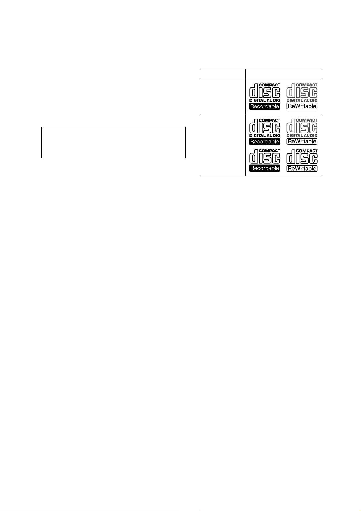
Notes on CD-Rs (recordable CDs)/CDRWs (rewritable CDs)
This unit can play the following discs:
Type of discs Label on the disc
Audio CD
MP3 files
•Some CD-Rs/CD- RWs (depending on the
equipment used for its recording or the
condition of the disc) may not play on this u nit.
•You cannot play a CD-R/CD-RW that is not
finalized*.
•You can play MP3 files recorded on CDROMs, CD-Rs, and CD-RWs.
•A CD-R/CD-RW to which a session can be
added can be played.
* A process necessary for a recorded CD-R/CD-RW
disc to be played on the audio CD player.
SAFETY-RELATED COMPONENT WARNING!!
COMPONENTS IDENTIFIED BY MARK 0 OR DOTTED
LINE WITH MARK 0 ON THE SCHEMATIC DIA GRAMS
AND IN THE PARTS LIST ARE CRITICAL TO SAFE
OPERATION. REPLACE THESE COMPONENTS WITH
SONY PARTS WHOSE PART NUMBERS APPEAR AS
SHOWN IN THIS MANU AL OR IN SUPPLEMENTS PUBLISHED BY SONY.
ATTENTION AU COMPOSANT AYANT RAPPORT
À LA SÉCURITÉ!
LES COMPOSANTS IDENTIFIÉS P AR UNE MARQUE 0
SUR LES DIAGRAMMES SCHÉMATIQUES ET LA LISTE
DES PIÈCES SONT CRITIQUES POUR LA SÉCURITÉ
DE FONCTIONNEMENT. NE REMPLACER CES COMPOSANTS QUE PAR DES PIÈCES SONY DONT LES
NUMÉROS SONT DONNÉS DANS CE MANUEL OU
DANS LES SUPPLÉMENTS PUBLIÉS PAR SONY.
3

MEX-1HD
Notes on MP3 files
MP3 (MPEG 1 Audio Layer-3) is a standard
technology and format for compressing a sound
sequence. The file is compressed to about 1/10 of
its original size. Sounds outside the range of
human hearing are compressed while the sounds
we can hear are not compressed.
Notes on discs
Yo u can play MP3 files recorded on CD-ROMs,
CD-Rs, and CD-RWs.
The disc must be in the ISO 9660*
level 2 format, or Joliet or Romeo in the
expansion format.
Yo u can use a disc recorded in Multi Session*
1
ISO 9660 Format
*
The most common international standard for
the logical format of files and folders on a
CD-ROM.
There are several specification levels. In
Level 1, file names must be in the 8.3 format
(no more than 8 characters in the name, no
more than 3 characters in the extension
“.MP3”) and in capital letters. Folder names
can be no longer than 8 characters. There can
be no more than 8 nested folder levels. Level
2 specifications allow file names up to 31
characters long.
Each folder can have up to 8 trees.
For Joliet or Romeo in the expansion format,
make sure of the contents of the writing
software, etc.
2
*
Multi Session
This is a recording method that enables
adding of data using the Track-At-Once
method. Conventional CDs begin at a CD
control area called the Lead-in and end at an
area called Lead-out. A Multi Session CD is a
CD having multiple sessions, with each
segment from Lead-in to Lead-out regarded
as a single session.
CD-Extra: The format which records audio
(audio CD data) as tracks on session 1, and
records data as tracks on session 2.
Mixed CD: In this format, data is recorded as
track, and audio (audio CD data) is recorded
as track 2.
1
level 1 or
Notes
• With formats other than ISO 9660 level 1 and level 2,
fold er names or file names may not be displayed
correctly.
• When naming, be sure to add the file extension
“.MP3” to the file name.
• If you put the extension “.MP3” to a file other than
MP3, the unit cannot recognize the file properly and
will generate random noise that could damage your
speakers.
• The following discs take a longer time to start
playback.
–a disc recorded with a complicated tree structure.
–a disc recorded in Multi Session.
–a disc to which data can be added.
Cautions when playing a disc that is recorded in
Multi Session
• When the first track of the first session is audio CD
2
.
data:
Only audio CD data is played back.
• When the first track of the first session is not audio
CD data:
– If an MP3 file is in the disc, only MP3 file(s) play
back and other data is skipped. (Audio CD data is
not recognized.)
– If no MP3 file is in the disc, “NO Music” is
displayed and nothing is played back. (Audio CD
data is not recognized.)
4

SECTION 1
SERVICING NOTES
MEX-1HD
Ver 1.1
NOTES ON HANDLING THE OPTICAL PICKUP BLOCK OR BASE UNIT
The laser diode in the optical pick-up block may suffer electrostatic breakdown because of the potential difference generated by
the charged electrostatic load, etc. on clothing and the human body .
During repair, pay attention to electrostatic breakdown and also
use the procedure in the printed matter which is included in the
repair parts.
The flexible board is easily damaged and should be handled with
care.
NOTES ON LASER DIODE EMISSION CHECK
The laser beam on this model is concentrated so as to be focused
on the disc reflective surface by the objective lens in the optical
pick-up block. Therefore, when checking the laser diode emission, observe from more than 30 cm away from the objectiv e lens.
Laser Diode Properties
• Material: GaAlAs
•Wavelength: 780 nm
• Emission Duration: continuous
• Laser Output Power: less than 44.6 µW*
*This output is the value measured at a distance of 200 mm
from the objective lens surface on the Optical Pick-up Block.
CHECKING THE VERSION BEFORE REPLACEMENT OF
FLASH MEMORY (IC1030 ON MAIN BOARD)
This set is available with two types, Initial Lot type and User Upgrade type, depending on the software version used in the microcomputer.
If the Flash Memory (IC1030 on MAIN board) or mounted MAIN
board was replaced, the work (*1) required after parts replacement is different according to the type. Therefore, before parts
replacement, check the type of set, and then perform the work
(*1) necessary for that type. However, if the version check is impossible because of a trouble in the set, handle it as a User Upgrade type.
*1: For the work required after parts replacement, refer to “Setup
After Parts Replacement” and “Ver sion Up After Microcomputer Software Related Parts Replacement” (page 22) in the
following section.
Procedure for check the version:
1. Select the “Test Mode” from the test mode main menu by rotating the right jog dial (PUSH LIST), and press the right jog
button (PUSH LIST) to enter the Test Mode.
2. Rotate the right jog dial (PUSH LIST) to select the “Version”,
and press the right jog button (PUSH LIST) to enter the Version mode.
3. With the “Version” mode activated, press the right jog button
(PUSH LIST), and the versions of Main, Sub, CD Servo will
be displayed respectively. Check the version of “Main”.
Version by type:
Initial Lot type : 1.00.05
User Upgrade type : 2.03.02
SETUP AFTER PARTS REPLACEMENT
This set requires the work such as microcomputer software version up, system ID setting and HDD formatting, if either of flash
memory, microcomputer (or mounted MAIN, SUB, or SERVO
board) and hard disk drive (HDD) was replaced.
Perform the work required by referring to the “Test mode”, if either of the following parts was replaced.
Replacement Version up System ID setting
parts and HDD processing
Flash memory
(IC1030 on MAIN
board) *1
Microcomputer
(IC501 on SUB
board) *1
Flash memory
(IC9 on SERVO
board) *1
HDD
*1: Including the case where the mounted board as a whole is re-
placed.
*2: Executing the HDD formatting causes the user’s recorded data
to be all erased, and therefore be careful not to execute this
operation by mistake if the HDD was not replaced.
aa
a –
a –
– a *2
Version up:
Refer to “Version Up After Microcomputer Software Related
Parts Replacement”.
System ID setting and HDD processing:
Refer to “Relating with ID”.
5
MEX-1HD
Ver 1.1
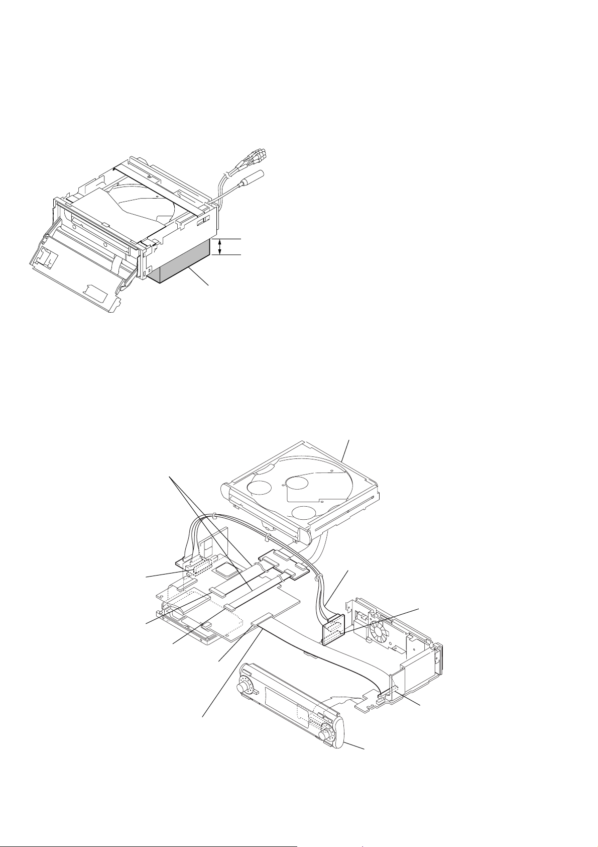
NOTE FOR THE OPENING OF THE FRONT PANEL
In this set, the front panel is lowered to below the bottom face
when it is opened.
When servicing the set, place it on a stand having a height of about
2 cm.
2 cm
stand
JIG ON REPAIRING
When repairing this set, connect the extension cables as the figure
shown below.
Connect jig (extension cables J-2502-069-3 :
0.5mm Pitch, 20/40 cores, Length 250mm)
to the mechanism deck and the main board
(CN2002, CN2003).
power board (CN702)
main board (CN2002)
main board (CN2003)
mechanism deck
Connect jig (extension cable J-2502-069-1 :
24 cores) to the power board (CN702) and
the sub board (CN525).
sub board (CN525)
main board (CN3002)
sub board (CN526)
Connect jig (extension cable J-2502-069-2 :
0.5mm Pitch, 50 cores, Length 300mm)
to the main board (CN3002) and
the sub board (CN526).
front panel section
6
SECTION 2
W
GENERAL
MEX-1HD
This section is extracted from
instruction manual.
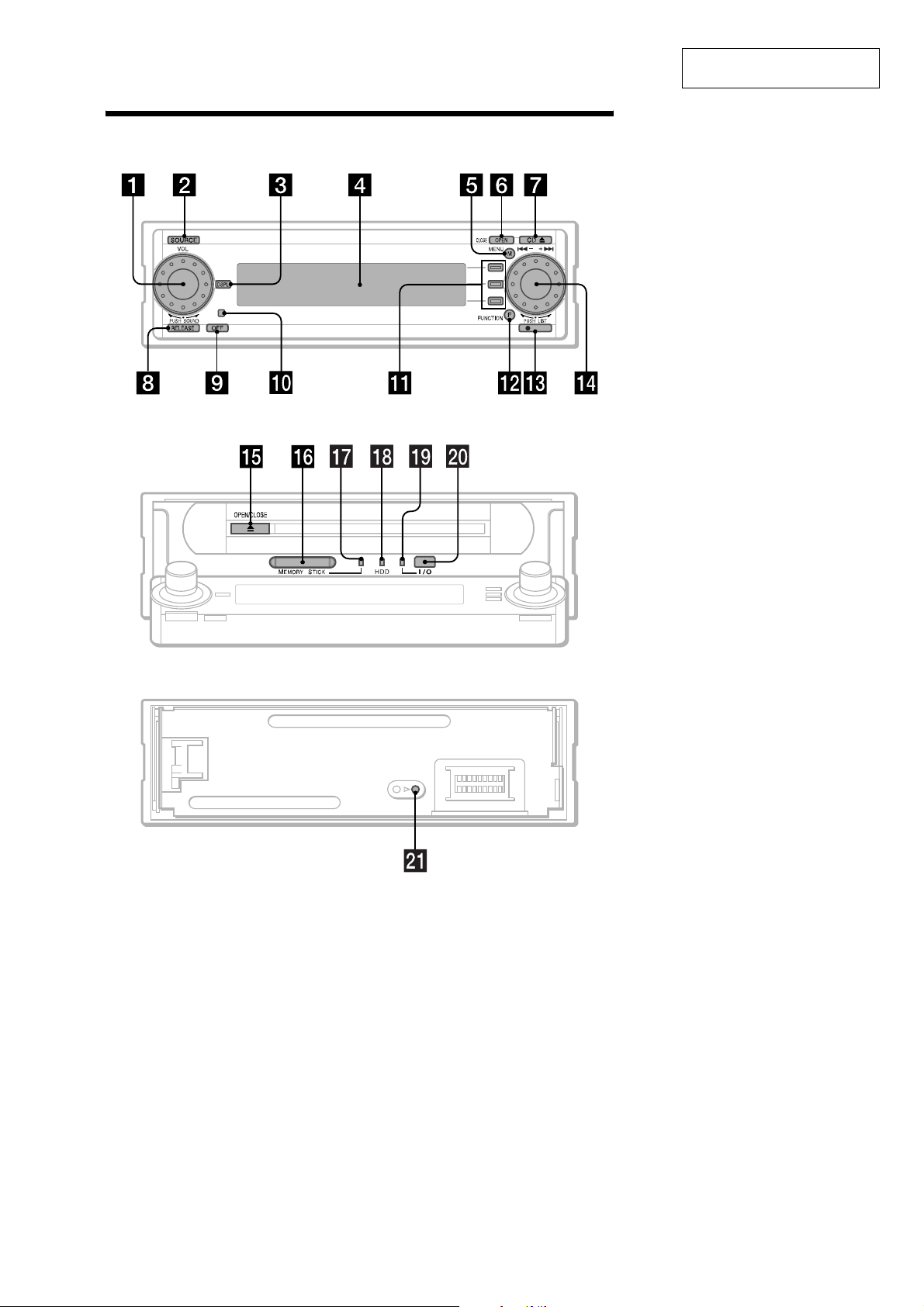
Location of controls
hen the front panel is opened
When the front panel is remove
a L (left) dial
Rotate to:
– Adjust the volume
– Select a sound item
Press to:
– Display the sound menu
– Enter a setting
b SOURCE button
To sel ect the source.
c DSPL button
d Display window
e MENU button
To display the menu s.
f OPEN (CLOSE) button
REC
d
g CD Z (eject) button
h RELEASE button
i OFF (Stop/Power of f) button*
j Receptor for remote commander
k F1/F2/F3 buttons
These buttons have different functions
depending on the si tu at i on.
l FUNCTION button
To change the function menu.
m z REC button
For record settings/to start recording.
n R (right) dial
Rotate to:
– Receive preset stations
– Skip tracks
– Select a menu item
Press to:
– Display the list
– Enter a setting
o Z (OPEN/CLOSE)
p “MG Memory Stick” Slot
q LED (“MG Memory Stick”)
Lights up while the unit is accessing the
“MG Memory Stick”.
r LED (HDD)
Lights up while the unit is accessing the
HDD.
s LED (I/O)
Lights up while the unit is accessing the
Digital I/O.
t Digital I/O terminal (4 pins)
To connect to the Network Walkman, etc.
u RESET button
* War ning when in s t a lling in a car without
an ACC (accessory) position on the
ignition switch
After turning off the ignition, be sure to press
on the unit for 2 seconds to turn off the
(OFF)
clock display.
Otherwise, the clock display does not turn off
and causes battery drain.
7
MEX-1HD
3
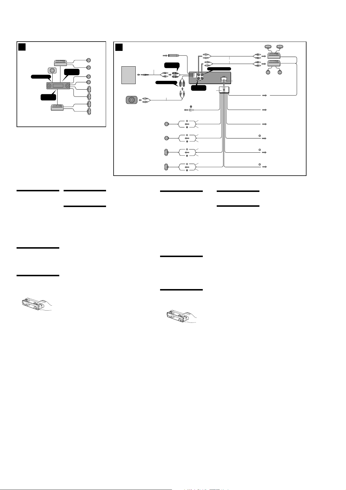
BUS AUDIO IN
SUB OUT (MONO)
AUDIO OUT
REAR
Cautions
•This unit is designed for negative ground 12 V
DC operation only.
•Do not get the wires under a screw, or caught
in moving parts (e.g. seat railing).
•Before making connections, turn the car
ignition off to avoid short circuits.
•Connect the yellow and red power input leads
only after all other leads have been connected.
•Run all ground wires to a common ground
point.
•Be sure to insulate any loose unconnected
wires with electrical tape for safety.
•The use of optical instruments with this
product will increase eye hazard.
Notes on the power supply cord (yellow)
•When connecting this unit in combination with
other stereo components, the connected car
circuit’s rating must be higher than the sum of
each component’s fuse.
•When no car circuits are rated high enough,
connect the unit directly to the battery.
Before installation ( 1)
Do not install the unit where its operation
interferes with driving.
Example:
—Opening and closing of the front panel or
disc tray interfere with operation of the gear
shift.
—With the front panel open, operation of
hazard lamps, switches etc., is impaired.
Parts Iist (2)
The numbers in the list are keyed to those in the
instructions.
Caution
Handle the bracket 1 carefully to avoid injuring
your fingers.
T
O
P
AUDIO OUT
FRONT
Connection example (3)
Note
Be sure to connect the ground cord before
connecting the amplifier.
Connection diagram (4)
1 To a metal surface of the car
• First connect the black ground lead, then
connect the yellow and red power input leads.
• Be sure to ground to the chassis of the car
securely.
2 To the power antenna control lead or power
supply lead of antenna booster amplifier
Notes
• It is not necessary to connect this lead if there
is no power antenna or antenna booster, or
with a manually-operated telescopic antenna.
•When your car has a built-in FM/AM antenna in
the rear/side glass, see “Notes on the control
and power supply leads.”
3 To AMP REMOTE IN of an optional power
amplifier
This connection is only for amplifiers. Connecting
any other system may damage the unit.
4 To the interface cable of a car telephone
5 To a car’s illumination signal
Be sure to connect the black ground lead to it
first.
6 To the +12 V power terminal which is energized
in the accessory position of the ignition key
switch
Notes
• If there is no accessory position, connect to the
+12 V power (battery) terminal which is
energised at all times.
Be sure to connect the black ground lead to it
first.
•When your car has a built-in FM/AM antenna in
the rear/side glass, see “Notes on the control
and power supply leads.”
7 To the +12 V power terminal which is energised
at all times
Be sure to connect the black ground lead to it
first.
4
Notes on the control and power supply leads
• The power antenna control lead (blue) supplies
+12 V DC when you turn on the tuner.
•When your car has built-in FM/AM antenna in the
rear/side glass, connect the power antenna control
lead (blue) or the accessory power input lead (red)
to the power terminal of the existing antenna
booster. For details, consult your dealer.
•A power antenna without relay box cannot be
used with this unit.
Memory hold connection
When the yellow power input lead is connected,
power will always be supplied to the memory circuit
even when the ignition key is turned off.
Notes on speaker connection
• Before connecting the speakers, turn the unit off.
•Use speakers with an impedance of 4 to 8 ohms,
and with adequate power handling capacities to
avoid its damage.
• Do not connect the speaker terminals to the car
chassis, or connect the terminals of the right
speakers with those of the left speaker.
• Do not connect the ground lead of this unit to the
negative (–) terminal of the speaker.
• Do not attempt to connect the speakers in parallel.
• Connect only passive speakers. Connecting active
speakers (with built-in amplifiers) to the speaker
terminals may damage the unit.
• To avoid a malfunction, do not use the built-in
speaker wires installed in your car if the unit shares
a common negative (–) lead for the right and left
speakers.
• Do not connect the unit’s speaker cords to each
other.
XM tuner
Récepter XM
DNR-XM01C
from car antenna
à partir de l’antenne de la
voiture
AUX IN
3
*
(AUDIO)
2
*
SUB OUT (MONO)
1
*
1
Left
Gauche
Right
Droit
Left
Gauche
Right
Droit
Prcautions
•Cet appareil est exclusivement conçu pour
fonctionner sur une tension de 12 V CC avec
masse négative.
•Evitez de fixer des vis sur les câbles ou de
coincer ceux-ci dans des pièces mobiles (par
exemple, armature de siège).
•Avant d’effectuer des raccordements, éteignez
le moteur pour éviter les courts-circuits.
•Raccordez les fils d’entrée d’alimentation
jaune et rouge seulement après avoir terminé
tous les autres raccordements.
•Rassemblez tous les fils de terre en un point
de masse commun.
•Veillez à isoler avec du chatterton tout fil lâche
non raccordé.
Remarques sur le cordon d’alimentation
(jaune)
•Lorsque cet appareil est raccordé à d’autres
appareils stéréo, la valeur nominale des
circuits de la voiture raccordée doit être
supérieure à la somme des fusibles de chaque
appareil.
•Si aucun circuit de la voiture n’est assez
puissant, raccordez directement l’appareil à la
batterie.
Avant linstallation ( 1)
N’installez pas l’appareil dans un endroit où il
pourrait gêner le conducteur dans ses
mouvements.
Exemple :
— dans un endroit où l’ouverture et la
fermeture de la façade ou du plateau de
disque pourraient nuire aux changements de
vitesse ;
— dans un endroit où l’ouverture de la façade
pourrait bloquer l’accès à l’interrupteur de
feux de détresse et aux autres commandes.
Liste des composants (2)
Les numéros de la liste correspondent à ceux des
instructions.
Attention
Manipulez avec précautions le support 1 pour
éviter de vous blesser aux doigts.
T
O
P
AUDIO OUT
REAR
Black
Noir
White
Blanc
White/black striped
Rayé blanc/noir
Gray
Gris
Gray/black striped
Rayé gris/noir
Green
Vert
Green/black striped
Rayé vert/noir
Purple
Mauve
Purple/black striped
Rayé mauve/noir
AUDIO OUT FRONT
L
R
FRONTAUDIO OUT REAR
5
Exemple de raccordement (3)
Remarque
Raccordez d’abord le fil de masse avant de raccorder
l’amplificateur.
Schma de raccordement (4)
1
À un point métallique de la voiture
•Branchez d‘abord le fil de masse noir et,
ensuite, les fils d‘entrée d‘alimentation jaune
et rouge.
•Assurez-vous de relier solidement le châssis du
véhicule à la masse.
2
Vers le fil de commande de l‘antenne électrique
ou le fil d‘alimentation de l‘amplificateur
d‘antenne
Remarques
• Il n'est pas nécessaire de raccorder ce fil s'il n'y
a pas d'antenne électrique ni d'amplificateur
d'antenne, ou avec une antenne télescopique
manuelle.
• Si votre voiture est équipée d'une antenne FM/
AM intégrée dans la vitre arrière/latérale, voir
“Remarques sur les fils de commande et
d'alimentation”.
3
Vers AMP REMOTE IN de l’amplificateur de
puissance en option
Ce raccordement s’applique uniquement aux
amplificateurs. Le branchement de tout autre
système risque d’endommager l’appareil.
4
Vers le câble d’interface d’un téléphone de
voiture
5
Au signal d’éclairage de la voiture
Raccordez d‘abord le fil de masse noir.
6
À la borne +12 V qui est alimentée quand la clé
de contact est sur la position accessoires
Remarques
• S'il n'y a pas de position accessoires, raccordez
la borne d'alimentation (batterie) +12 V qui
est alimentée en permanence.
Raccordez d‘abord le fil de masse noir.
• Si votre voiture est équipée d'une antenne FM/
AM intégrée dans la vitre arrière/latérale, voir
“Remarques sur les fils de commande et
d'alimentation”.
7
À la borne +12 V qui est alimentée en permanence
Raccordez d‘abord le fil de masse noir.
1
*
Fuse (10 A)
Fusible (10 A)
Blue/white striped
Rayé bleu/blanc
Blue
Max. supply current 0.1 A
Courant max. fourni 0,1 A
Bleu
Light blue
Bleu ciel
Orange/white striped
Rayé orange/blanc
Red
Rouge
Yellow
Jaune
ANT REM
ILLUMINATION
AMP REM
3
Max. supply current 0.3 A
Courant max. fourni 0,3 A
2
4
ATT
*1RCA pin cord (not supplied)
Cordon à broche RCA (non fourni)
5
2
*
RK-G129 (Stereo mini plug to Phono
plug) (not supplied)
RK-G129 (mini-prise stéréo allant à
la prise Phono) (non fournie)
3
*
Be sure to match the color-coded
code for audio to the appropriate
6
jacks from the unit.
Veillez à faire correspondre le code
couleur audio aux fiches de
l’appareil.
7
Remarques sur les fils de commande et
d'alimentation
• Le fil de commande de l’antenne électrique (bleu)
fournit une alimentation de + 12 V CC lorsque vous
mettez la radio sous tension.
• Lorsque votre voiture est équipée d’une antenne
FM/AM intégrée dans la vitre arrière/latérale,
raccordez le fil de commande de l’antenne (bleu)
ou le fil d’entrée d’alimentation des accessoires
(rouge) à la borne de l’amplificateur d’antenne
existant. Pour plus de détails, consultez votre
détaillant.
• Une antenne électrique sans boîtier de relais ne
peut pas être utilisée avec cet appareil.
Raccordement pour la conservation de la mémoire
Lorsque le fil d’entrée d’alimentation jaune est
raccordé, le circuit de la mémoire est alimenté en
permanence même si la clé de contact est sur la
position d’arrêt.
Remarques sur le raccordement des haut-parleurs
• Avant de raccorder les haut-parleurs, mettez
l’appareil hors tension.
•Utilisez des haut-parleurs ayant une impédance de
4 à 8 ohms avec une capacité de manipulation
adéquate pour éviter de les endommager.
• Ne raccordez pas les bornes du système de hautparleur au châssis de la voiture et ne raccordez pas
les bornes du haut-parleur droit à celles du hautparleur gauche.
• Ne raccordez pas le câble de masse de cet appareil
à la borne négative (–) du haut-parleur.
•N’essayez pas de raccorder les haut-parleurs en
parallèle.
• Raccordez uniquement des haut-parleurs passifs.
Le raccordement de haut-parleurs actifs (avec
amplificateurs intégrés) aux bornes des hautparleurs peut endommager l’appareil.
• Pour éviter tout dysfonctionnement, n’utilisez pas
les fils des haut-parleurs intégrés installés dans
votre voiture si l’appareil partage un fil négatif
commun (–) pour les haut-parleurs droit et gauche.
• Ne raccordez pas entre eux les cordons des hautparleurs de l’appareil.
8
MEX-1HD
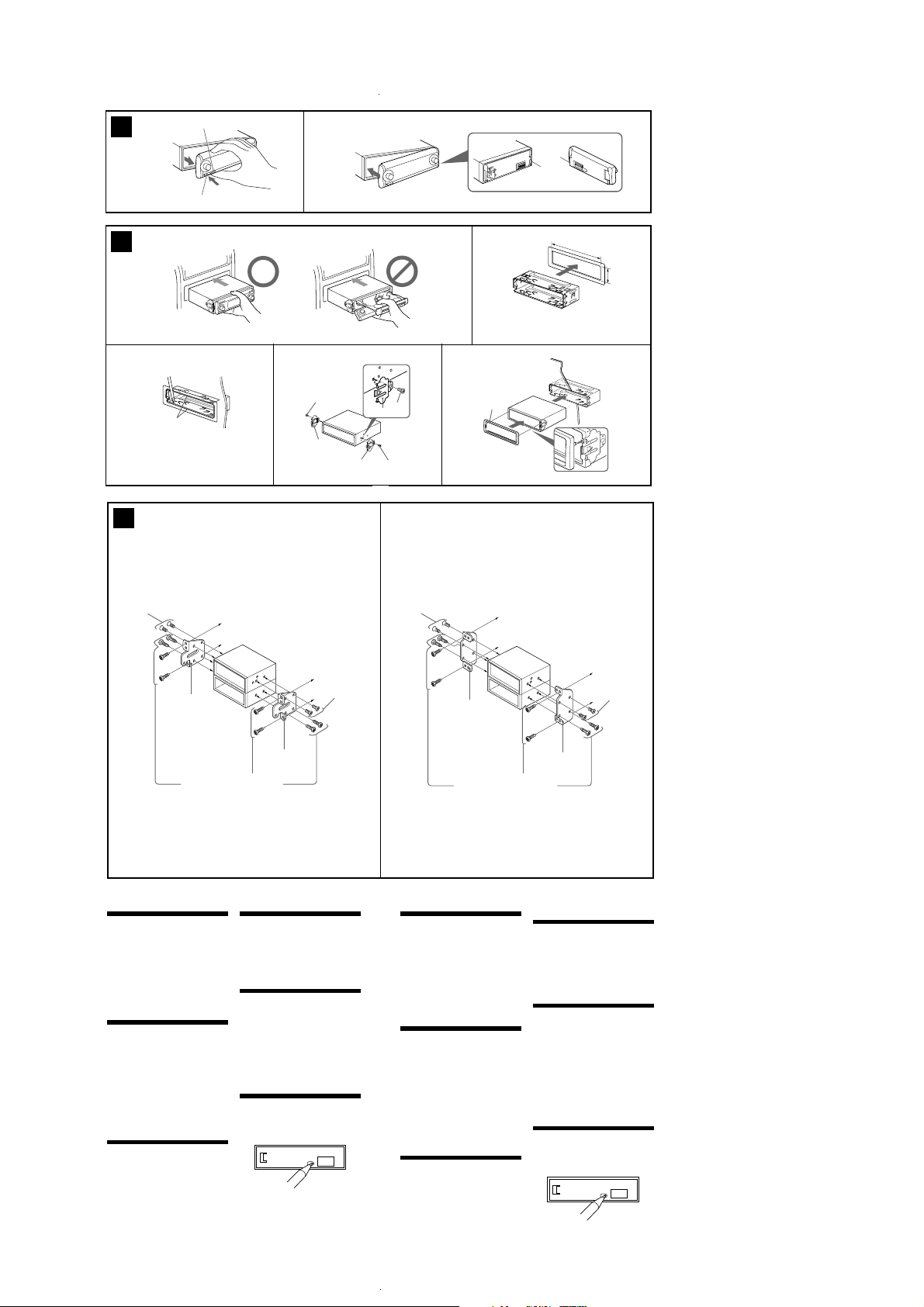
5 AB
(OFF)
A
B
(RELEASE)
6
*
234
Bend these claws outward
for a tight fit, if necessary.
Pliez ces griffes vers l’extérieur pour
assurer une prise correcte si nécessaire.
2
3
2
3
3
2
1
1
1
8
2
m
m
T
O
P
with the TOP marking up
avec l’inscription TOP vers le haut
Dashboard
Tableau de bord
TOP
1
4
7
A
TOYOTA
B
NISSAN
5
3
m
m
6
max. size
5 × 6 mm
7
(
/32 × 1/4 in.)
Dimension
max. 5 × 6 mm
7
/32 × 1/4 po.)
(
Bracket
Support
Existing parts supplied with your car
Pièces existantes fournies avec la voiture
Precautions
•Choose the installation location carefully so
that the unit will not interfere with normal
driving operations.
•Avoid installing the unit in areas subject to
dust, dirt, excessive vibration, or high
temperatures, such as in direct sunlight or near
heater ducts.
•Use only the supplied mounting hardware for
a safe and secure installation.
Mounting angle adjustment
Adjust the mounting angle to less than 30°.
How to detach and attach the
front panel ( 5)
Before installing the unit, detach the front
panel.
5-A To detach
Before detaching the front panel, be sure to
press (OFF). Press (RELEASE) to open up the
front panel and pull it off towards you.
5-B To attach
Attach part A of the front panel to part B of the
unit as illustrated and push the left side into
position until it clicks.
Mounting example ( 6)
Installation in the dashboard
When installing this unit, be sure to close the
front panel of the unit. (6-*)
Do not hold the unit by its front panel or disc
tray when installing as this can damage the unit,
or cause malfunction.
to dashboard/center console
au tableau de bord/console centrale
6
max. size
5 × 6 mm
7
(
/32 × 1/4 in.)
Dimension
max. 5 × 6 mm
7
/32 × 1/4 po.)
(
Bracket
Support
Mounting the unit in a Japanese
car (7)
You may not be able to install this unit in some
makes of Japanese cars. In such a case, consult
your Sony dealer.
Note
To prevent malfunction, install only with the
supplied screws 6.
Warning when installing in a car
without ACC (accessory)
position on the ignition key
switch
Be sure to press (OFF) on the unit for two
seconds to turn off the clock display after
turning off the engine.
When you press (OFF) only momentarily, the
clock display does not turn off and this causes
battery wear.
RESET button
When the installation and connections are
completed, be sure to press the RESET button
with a ball-point pen, etc., after removing the
front panel.
6
max. size
5 × 6 mm
7
(
/32 × 1/4 in.)
Dimension
max. 5 × 6 mm
7
/32 × 1/4 po.)
(
Bracket
Support
Existing parts supplied with your car
Pièces existantes fournies avec la voiture
Prcautions
•Choisissez soigneusement l’emplacement
d’installation pour que l’appareil ne gêne pas
le chauffeur pendant la conduite.
•Evitez d’installer l’appareil dans un endroit
exposé à la poussière, à la saleté, à des
vibrations excessives ou à des températures
élevées comme en plein soleil ou à proximité
de conduits de chauffage.
•Pour garantir un montage sûr, n’utilisez que le
matériel fourni.
Rglage de langle de montage
Ajustez l’inclinaison à un angle inférieur à 30°.
Retrait et pose de la fa ade (5)
Avant d’installer l’appareil, retirez la façade.
5-A Pour retirer
Avant de déposer la façade, n’oubliez pas
d’appuyer sur (OFF). Appuyez sur (RELEASE)
pour ouvrir la façade, puis retirez-la en tirant
vers vous.
5-B Pour poser
Fixez la partie A de la façade sur la partie B de
l’appareil, comme indiqué sur l’illustration, puis
poussez le côté gauche pour le mettre en place
jusqu’au déclic.
Exemple de montage (6)
Installation dans le tableau de bord
Pendant l’installation de l’appareil, vérifiez
que le panneau avant de cet appareil est
)
fermé. (6-
*
Ne tenez pas l’appareil par la façade ou le
plateau de disque lors de l’installation, car cela
risque d’endommager l’appareil ou d’entraîner
un problème de fonctionnement.
to dashboard/center console
au tableau de bord/console centrale
6
max. size
5 × 6 mm
7
/32 × 1/4 in.)
(
Dimension
max. 5 × 6 mm
7
/32 × 1/4 po.)
(
Bracket
Support
Installation de l appareil dans
une voiture japonaise ( 7)
Cet appareil ne peut pas être installé dans
certaines voitures japonaises. Consultez, dans ce
cas, votre revendeur Sony.
Remarque
Pour éviter tout dysfonctionnement, utilisez
uniquement les vis 6 pour le montage.
Avertissement en cas
dinstallation dans une voiture
dont le contact ne comporte
pas de position ACC
(accessoires)
Noubliez pas dappuyer sur le bouton
(OFF) de lappareil pendant deux
secondes aprs avoir coup le moteur de
faon dsactiver laffichage de l horloge.
Si vous appuyez brièvement sur (OFF),
l’affichage de l’horloge n’est pas désactivé, ce
qui provoque une usure de la batterie.
Touche RESET
Après avoir retiré la façade, une fois que
l’installation et les raccordements sont terminés,
appuyez sur la touche RESET avec un stylo à
bille, etc.
9
MEX-1HD
Ver 1.1
SECTION 3
DISASSEMBLY
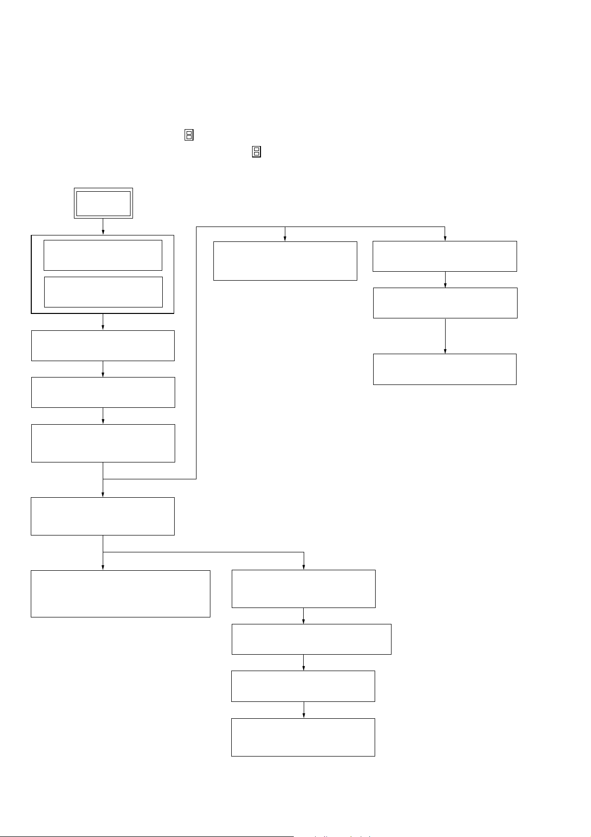
3-1. DISASSEMBLY FLOW
• This set can be disassembled in the order shown below.
Note 1: The process described in can be performed in any order.
Note 2: Without completing the process described in , the next process can not be performed.
Note 3: Illustration of disassembly is omitted.
SET
FRONT PANEL ASSY
(Note 3)
3-2. COVER
(Page 11)
3-3. BASE PANEL ASSY
(Page 11)
3-4. SUB PANEL (CD) ASSY
(Page 12)
3-5. MECHANISM DECK
(MG-550D-156)
(Page 12)
3-6. MOTOR BLOCK ASSY,
CAM BLOCK ASSY
(Page 13)
3-12. BELT (L), LE MOTOR ASSY
(TRAY OPEN/CLOSE) (M103)
(Page 16)
3-13. TRAY (UD) ASSY
(Page 17)
3-14. OP ASSY (CDM-3021EBG)
(Page 17)
3-15. SERVO BOARD
(Page 18)
3-7. MOTOR ASSY
(FRONT PANEL OPEN/CLOSE) (M601),
SWITCH BOARD
(Page 13)
10
3-8. MAIN BOARD,
POWER BOARD
(Page 14)
3-9. HARD DISK DRIVE (2.5 inch) UNIT
(Page 15)
3-10. SUB BOARD
(Page 15)
3-11. HEAT SINK,
DC FAN (M501)
(Page 16)
Note: Follow the disassembly procedure in the numerical order given.
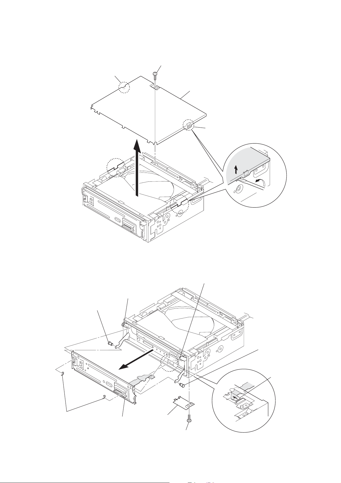
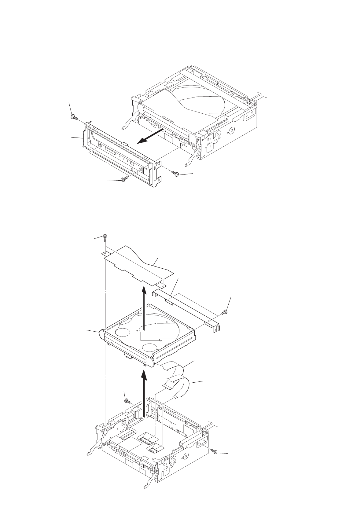
3-2. COVER
1
2
boss
screw
(PTT2.6 × 4)
3
cover
2
MEX-1HD
boss
3-3. BASE PANEL ASSY
5
shaft (base panel, D)
4
four E rings
(panel)
7
base panel assy
6
boss
2
cover
(chassis)
6
boss
5
shaft (base panel, D)
3
mounted flexible PWB
(FP) (CN524)
1
screw
(PTT2.6
×
4)
11
MEX-1HD
)
)
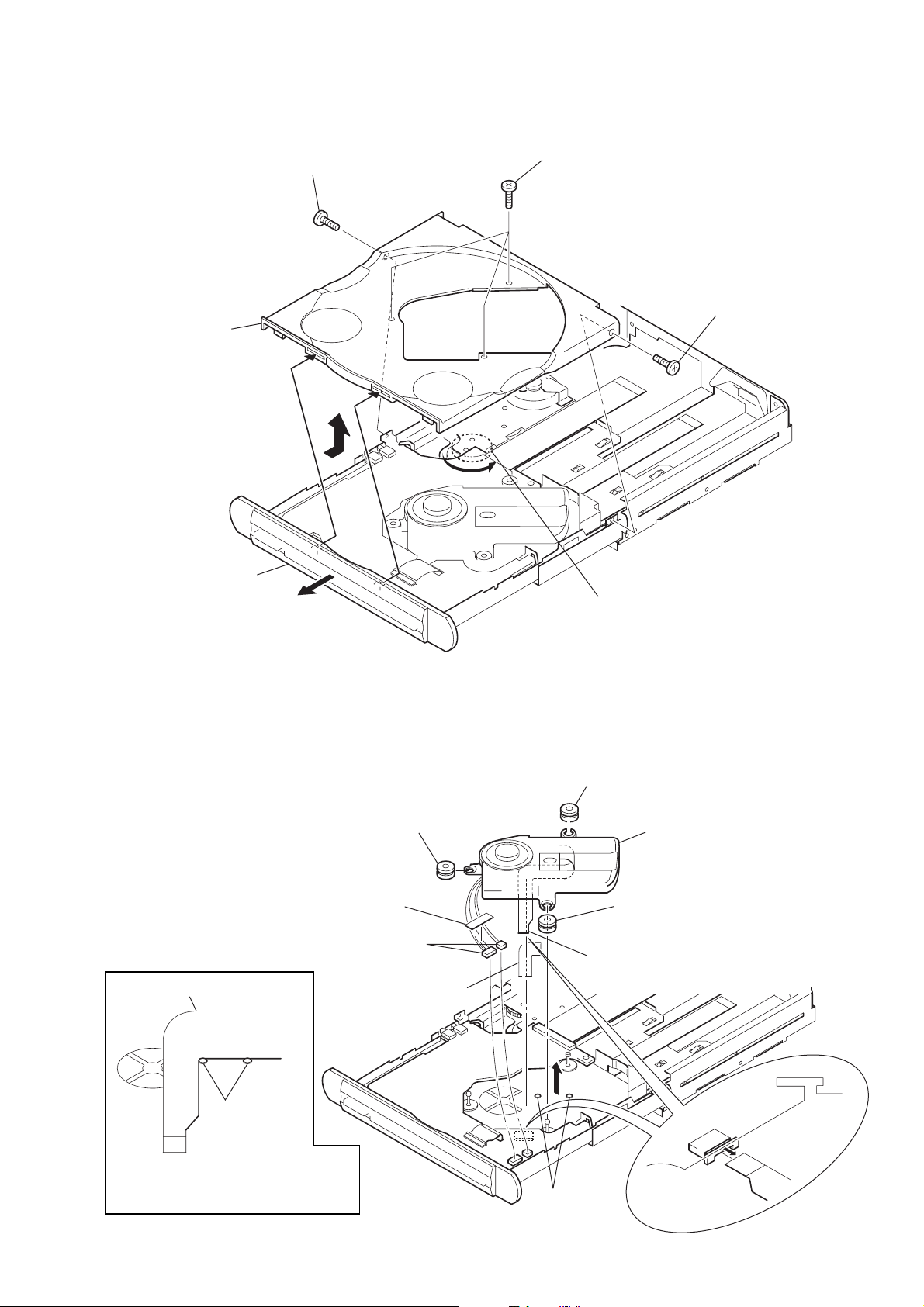
3-4. SUB PANEL (CD) ASSY
1
screw
(PTT2.6 × 6)
2
sub panel (CD) assy
1
two screws
(PTT2.6 × 6)
1
screw
(PTT2.6 × 6)
3-5. MECHANISM DECK (MG-550D-156)
1
two screws
(PTT2.6 × 6)
9
mechanism deck (MG-550D-156)
3
screw
(PTT2.6 × 4)
4
2
bracket (cover)
8
bracket (tray)
6
D40P flexible board
(CN2002)
5
7
two screws
(PTT2.6 × 4
D20P flexible board
(CN2003)
12
3
screw
(PTT2.6 × 4

3-6. MOTOR BLOCK ASSY, CAM BLOCK ASSY
r
2
6
motor block assy
screw
(PTT2.6
×
6)
3
4
cover (protection)
1
screw
(PTT2.6 × 6)
5
connector
(CN411)
8
7
two screws
(PTT2.6
MEX-1HD
×
6)
9
cam block assy
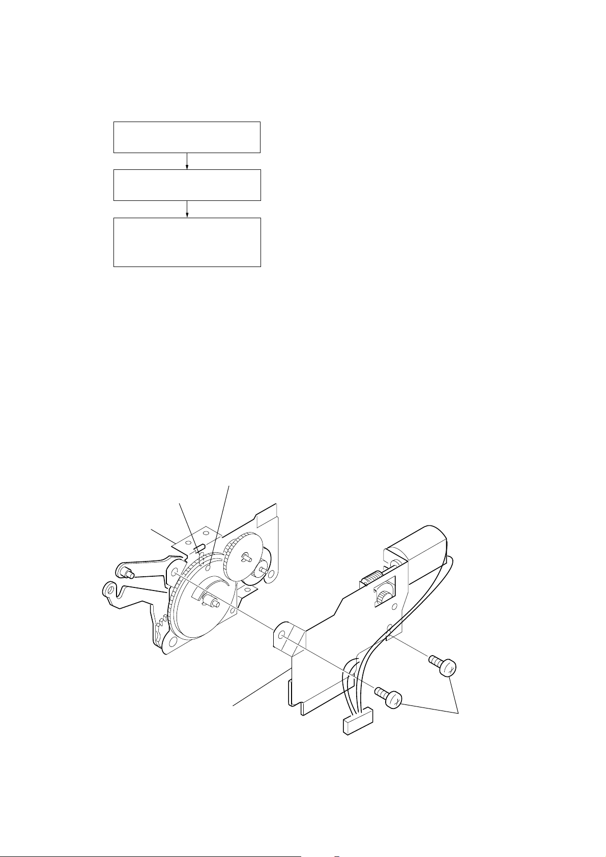
3-7. MOTOR ASSY (FRONT PANEL OPEN/CLOSE) (M601), SWITCH BOARD
1
Remove two solders of
the front panel open/close moto
lead wires.
9
motor assy
(front panel open/close)
(M601)
6
ring E-2 retaining
7
gear (worm wheel)
3
8
two screws
(P2
×
2.5)
4
ground point screw
(PTT2.6
×
6)
5
switch board
2
two screws
(PTT2.6
×
6)
13
MEX-1HD
e
Ver 1.1
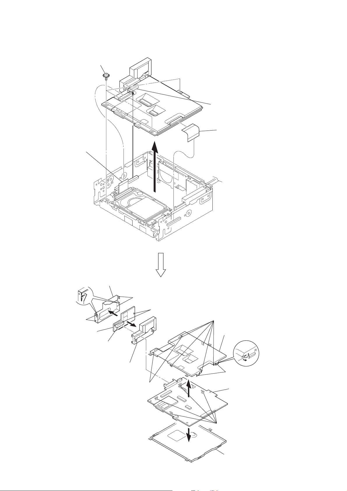
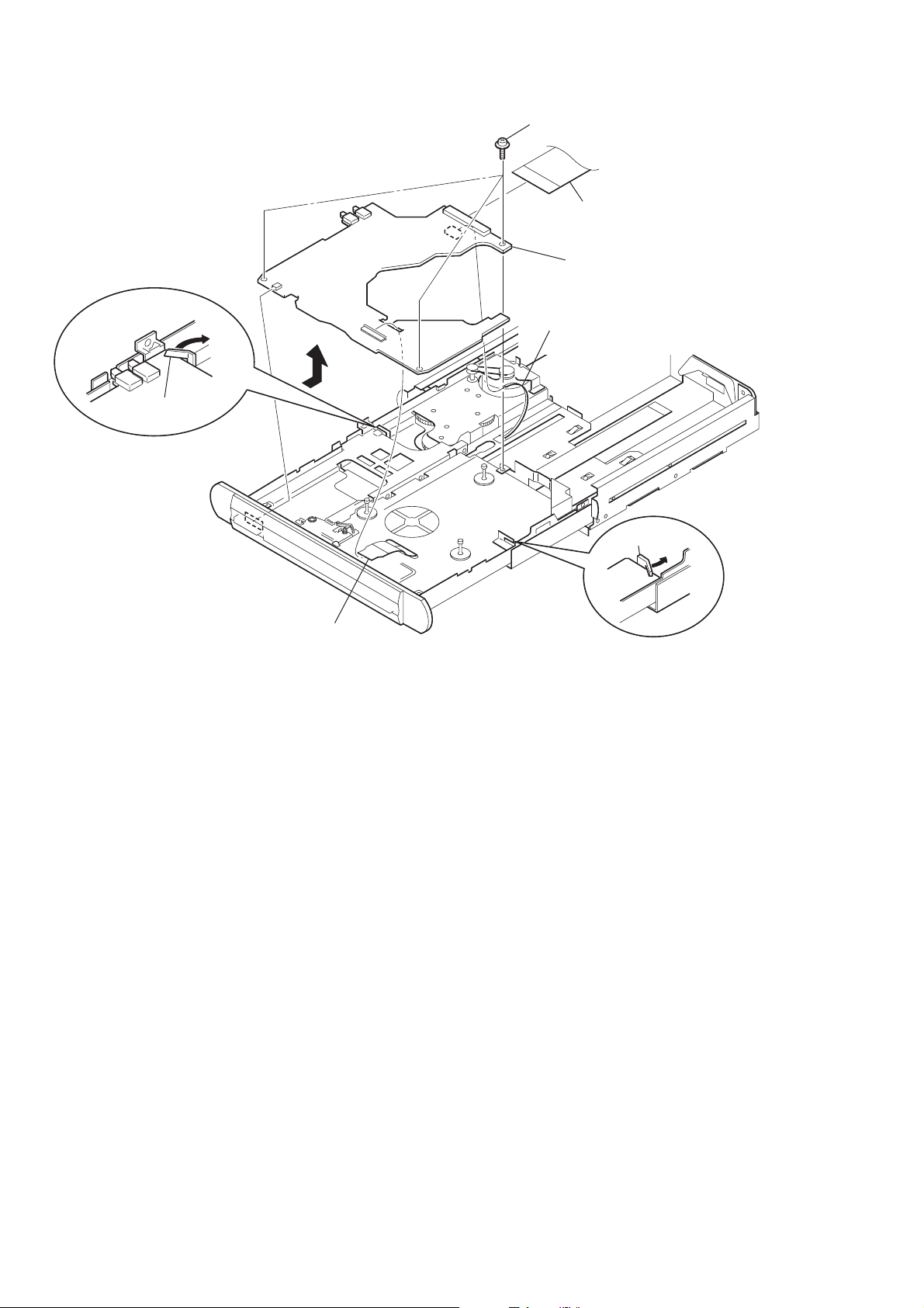
3-8. MAIN BOARD, POWER BOARD
3
three ground point screws
(PTT2.6
2
mounted PWB
(HDD connector)
(CN2001)
×
6)
4
connector (CN525)
1
flexible flat 50P cabl
(CN526, CN3002)
9
Bend two claws.
6
two bosses
qa
power board
5
connector
(CN3001)
0
sheild (DC2)
7
sheild (DC1)
qs
two claws
6
two bosses
8
Remove two solders.
qg
Bend six claws.
qh
shield (top)
qs
two claws
qj
main board
qf
Remove five solders.
14
qd
shield (bottom)
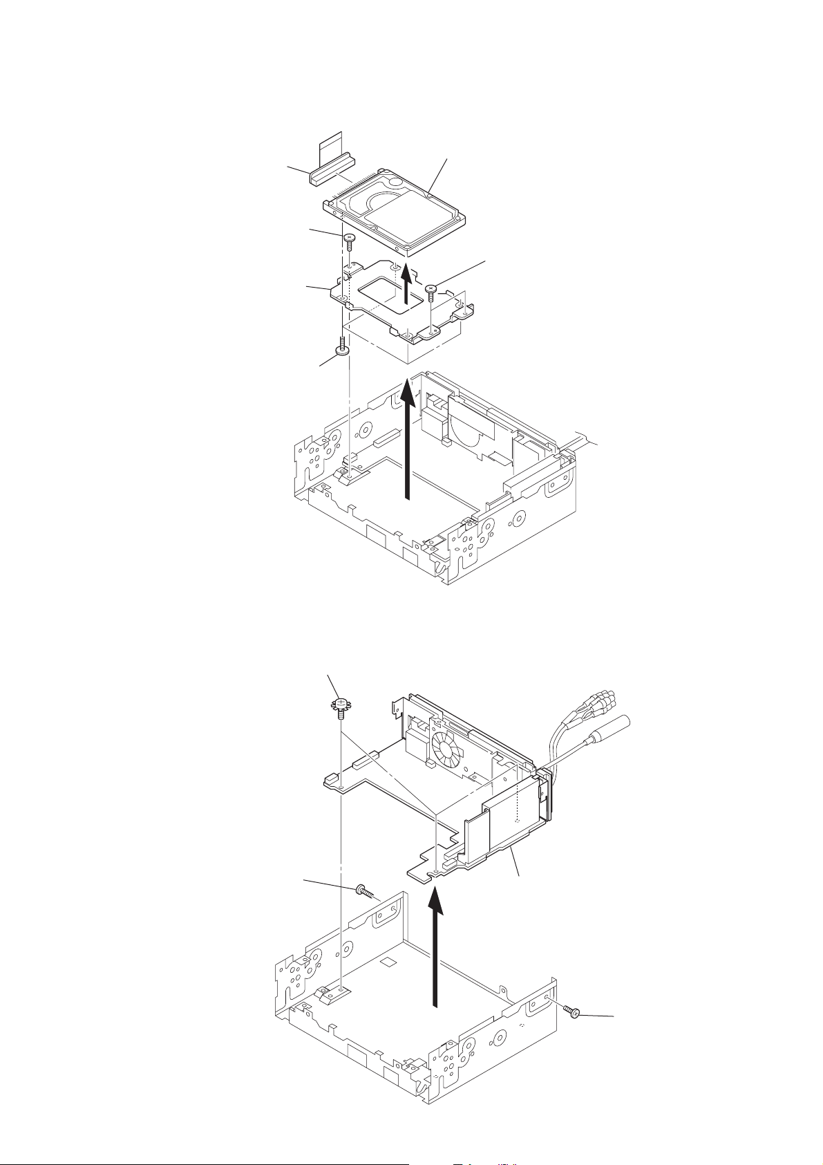
3-9. HARD DISK DRIVE (2.5 inch) UNIT
t
6
mounted PWB
(HDD connector)
1
screw
(B2.6
×
4)
5
bracket (H)
3
four screws
(M3
×
4)
4
7
hard disk drive (2.5 inch) uni
1
two screws
(B2.6 × 4)
MEX-1HD
3-10. SUB BOARD
2
three ground point screws
(PTT2.6
×
6)
2
1
screw
(PTT2.6 × 4)
3
4
sub board
1
screw (PTT2.6 × 4)
15
MEX-1HD
Ver 1.1
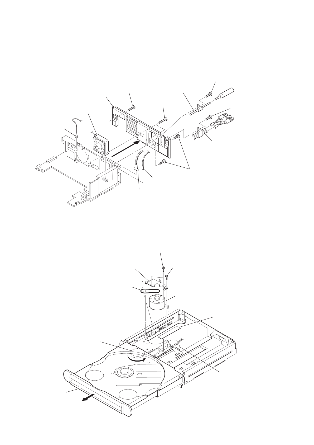
3-11. HEAT SINK, DC FAN (M501)
4
heat sink
qa
DC fan (M501)
0
connector
(CN528)
2
screw
(PTT2.6
×
8)
3
two screws
(PTT2.6
7
connection cord
(ANT)
×
16)
5
screw
(PTT2.6
9
×
connection cord (AUX)
(AUX IN/SUB OUT)
6)
1
screw
(PTT2.6
×
6)
6
terminal
(J101)
8
connector
(CN301)
3-12. BELT (L), LE MOTOR ASSY (TRY OPEN/CLOSE) (M103)
7
two screws (P1.7 × 2)
8
bracket (motor)
3
belt (L)
2
two screws
(PTT2.6
6
screw (M1.7)
LE motor assy (tray open/close) (M103)
9
×
8)
4
saranet cushion (FPC)
1
2
Draw out the tray block
(D) assy fully in the
direction of arrow B.
16
Rotate the gear (5) in the
direction of arrow A
to release the mecha-lock.
B
A
5
Remove two solders of
the LE motor assy
(tray open/close) (M103)
lead wires.
3-13. TRAY (UD) ASSY
)
3
screw (M1.7 × 2.5)
5
tray (UD) assy
4
A
3
three screws (M1.7 × 2.5)
3
screw (M1.7 × 2.5
MEX-1HD
Ver 1.1
2
Draw out the tray block
(D) assy fully in the
direction of arrow
B
.
B
3-14. OP ASSY (CDM-3021EBG)
Note: Do not reuse the adhesive sheet (MD)
after removing the OP assy (CDM-3021EBG).
Be sure to replace a brand-new adhesive sheet (MD).
1
saranet cushion
2
two connectors (CN2, CN3)
base flexible board
4
adhesive sheet (MD)
6
insulator
1
Rotate the gear (5) in the direction
of arrow
6
insulator
6
5
base flexible board (CN1)
A
to release the mecha-lock.
7
OP assy (CDM-3021EBG)
insulator
positioning
dowels
Note: To install the base flexible board,
fix it along the dowels on the tray.
3
positioning
dowels
17
MEX-1HD
Ver 1.1
3-15. SERVO BOARD
1
Bend the claw.
5
4
three screws (M2 × 3.5)
3
D40P flexible board (CN7)
7
servo board
6
motor flexible board (CN5)
1
Bend the claw.
2
D20P flexible board (CN6)
18
4-1. ASSEMBLY FLOW
)
• This set can be assembled in the order shown below.
4-2. MOTOR BLOCK ASSY
(Page 19)
4-3. CAM BLOCK ASSY
(Page 20)
4-4. PHASE ALIGNMENT OF
MOTOR BLOCK ASSY AND
CAM BLOCK ASSY
(Page 20)
SECTION 4
ASSEMBLY
MEX-1HD
Ver 1.1
Note: Follow the assembly procedure in the numerical order given.
4-2. MOTOR BLOCK ASSY
1
Align the gear (cam L) position setting hole with
the center mark on the bracket (main L) assy.
center mark
bracket (main L) assy
2
bracket (sub, L) assy
3
two screws (PTT2.6 × 6
19
MEX-1HD
y
Ver 1.1
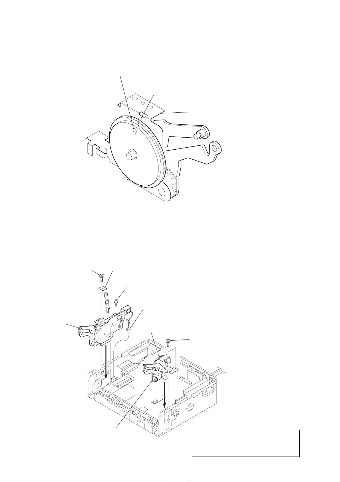
4-3. CAM BLOCK ASSY
1
Align the gear (cam R) position setting hole with
the center mark on the bracket (main R) assy.
center marking
bracket (main R) ass
4-4. PHASE ALIGNMENT OF MOTOR BLOCK ASSY AND CAM BLOCK ASSY
5
2
motor block assy
screw (PTT2.6 × 6)
4
cover (protection)
3
screw (PTT2.6 × 6)
gear (cam R)
1
connector (CN411)
7
two screws (PTT2.6 × 6)
20
6
cam block assy
Note : Touch the gear (cam R) with fingers in the
direction of rotation and make sure that
there is no phase difference with the motor
block assy side position setting hole.

SECTION 5
TEST MODE
MEX-1HD
Ver 1.2
Note: The test mode of this set contains the items not used for the
service. If you activated another mode by mistake, press the function button 1 or the
Particularly, for the menu commands and Factory Setting saved
in the HDD menu, never execute them except when the hard
disk drive was replaced. Otherwise, the hard disk drive will not
operate or the data saved by the user in the hard disk will be
erased.
[M] (Menu) button to deactivate that mode.
[ENTERING THE TEST MODE]
1. In the standby state, perform the following operation.
(1) Rotate clockwise the right jog dial (PUSH LIST) 4 clicks.
(2) Press the left jog button (PUSH SOUND).
(3) Rotate counterclockwise the right jog dial (PUSH LIST) 5
clicks.
(4) Press the left jog button (PUSH SOUND).
(5) Rotate clockwise the right jog dial (PUSH LIST) 1 click.
(6) Press the left jog button (PUSH SOUND) for more than 2
seconds.
2. When the test mode is activated, a peep will be heard and the
“TEST MODE” will be displayed on the screen. (“TEST
MODE” disappears soon)
3. Press the [M] (Menu) button, and the test mode main menu
screen will be displayed.
[RELEASING THE TEST MODE]
To release the test mode, perform either of the following operations.
•Turn the main power off.
• Remove the front panel.
•Press the [OFF] button for more than 2 seconds.
Note: In exiting the test mode, the system is reset automatically and the
data are erased. Then, when the power is turned on again, the initial setting (AM 9K/10K step choice, date and time setting) screen
is displayed, but this setting is also erased in certain time after the
main power was turned off.
Accordingly, re-setting is not necessary but normal operation and
the test mode operation are disabled unless the initial setting has
completed. In such a case, therefore, press the right jog button
(PUSH LIST) repeatedly and enter tentative initial set values.
[BASIC OPERATION]
In the test mode, basically the following dial and buttons are used
for the operation.
• Right jog dial (PUSH LIST) : Selects an item.
• Right jog button (PUSH LIST) : Enters the selected item.
• Function button 1 : Returns to the one-level high-
er menu
[DIAGNOSTIC FUNCTION]
Procedure:
1. Select the “Test Mode” from the test mode main menu by rotating the right jog dial (PUSH LIST), and press the right jog
button (PUSH LIST) to enter the Test Mode.
2. Rotate the right jog dial (PUSH LIST) to select the “DIAG”,
and press the right jog button (PUSH LIST) to enter the DIAG
mode.
3. With the “ALL -Auto-” selected, pressing the right jog button
(PUSH LIST) allows all of the following items to be checked
automatically.
• PEACOCK (MAIN board IC2003)
• HUMMING BIRD (MAIN board IC3003)
• ISP1161 (MAIN board IC4301)
• CXD1859 (MAIN board IC4001)
• E2PROM (MAIN board IC4002) *1
•ATA0 (HDD) (Hard disk drive) *2
• ATA1 (CDD) (CD servo block)
• WM (USB connection) *3
•RTC (SUB board IC502)
*1) A checking without inserting a memory stick causes an
error, and the “E2PROM NO MS” is displayed.
*2) If the ATA0 (HDD) check results in NG, try to repeat the
check several times.
If repetitional check results in NG, a communication error is doubtful, besides faulty hard disk drive.
*3) A checking without connecting the USB causes an error,
and the “NWWM NG!” is displayed.
4. After automatic check of all items completed, if all items are
OK, “OK ALL” will be displayed. In case of erroneous items,
NG indication is given to respective erroneous items.
5. To return to the DIAG menu, press the left jog button (PUSH
SOUND).
[VERSION DISPLAY]
Besides the version display for the users in normal mode, the version of each section of the system is displayed.
Procedure:
1. Select the “Test Mode” from the test mode main menu by rotating the right jog dial (PUSH LIST), and press the right jog
button (PUSH LIST) to enter the Test Mode.
2. Rotate the right jog dial (PUSH LIST) to select the “Version”,
and press the right jog button (PUSH LIST) to enter the Version mode.
3. With the “Version” mode activated, pressing the right jog button (PUSH LIST) allows the following versions to be displayed:
• Main (version of main section)
• Sub (version of sub section)
• CD (version of CD servo section)
[Making CD-R For Service]
At the replacement of parts, this set may require jobs such as version updating of the main section and sub section and data installing to a HDD, and for these jobs, the CD-R for service is needed.
Make the CD-R for service by downloading the data from the “ftp”
server for service. The data to be downloaded are available with
two types, for initial lot type and for upgraded type, and further as
regards the upgraded type, the latest version at that time must be
confirmed, thus requiring extreme care. (See table “The version
of each section” on page 22)
Note on making CD-R: The file format should be ISSO9660.
Store all files in the ROOT directory.
21

MEX-1HD
Ver 1.2
[VERSION UP AFTER MICROCOMPUTER SOFTWARE RELATED PARTS REPLACEMENT]
If either of the following ICs was replaced with new one, the part
supplied for repair contains old version programs, and thus the
version of microcomputer software must be updated.
1) Main section (when IC1030 was replaced)*
1-1. MAIN board replacement
1-2. Flash memory (IC1030 on the MAIN board) replacement
2) Sub section (when IC501 was replaced)
2-1. SUB board replacement
2-2. Microcomputer (IC501 on the SUB board) replacement
3) CD servo section (when IC9 was replaced)
3-1. SERVO board replacement
3-2. Flash memory (IC9 on the SERVO board) replacement
*) If the flash memory (IC1030 on the MAIN board) or MAIN
board was replaced, the work including the system ID setting
is required, besides this work described here. For details, see
“Relating with ID” in the next paragraph, after the completion
of this work.
Procedure:
• Check the versions
1. After replacing the parts, turn the power on and enter the test
mode. (Refer to page 21 “Entering The Test Mode”)
2. Select the “Test Mode” from the test mode main menu by rotating the right jog dial (PUSH LIST), and press the right jog
button (PUSH LIST) to enter the Test Mode.
3. Rotate the right jog dial (PUSH LIST) to select the “Version”,
and press the right jog button (PUSH LIST) to enter the Version mode.
4. Rotate the right jog dial (PUSH LIST) to select the “Version”,
and press the right jog button (PUSH LIST) to display the version of each section (main, sub, CD servo)
5. Update the version in each section by referring to the operation for version up, if each version is not as listed below.
The version of each section:
Section Initial Lot type User Upgrade type
Main 1.00.05 2.03.0D *
Sub 1.00.02 1.00.0D *
CD servo 0.03.60 0.03.60 *
*) There are several kinds of versions in the upgraded type (CDDB
compatible), and this table lists the latest version as of the end
of May in 2003.
The latest version may be updated after this Service Manual
was issued, and therefore make sure the latest version by referring to the Technical News issued at the version updating.
(1) Main Section
Note (for User Upgrade type only):
The version updating work must be performed without connecting
the HDD, if only the flash memory (IC1030 on MAIN board) or the
MAIN board is replaced without replacing the HDD at the same time.
In this case, perform the version updating work with the flat cable
between CN2001 on MAIN board and HDD disconnected, and after
the version updating completed, reconnect it.
1. Chech the version of CD-R for service and insert the disc to
the set.
2. Select the “Test Mode” from the test mode main menu by rotating the right jog dial (PUSH LIST), and press the right jog
button (PUSH LIST) to enter the Test Mode.
3. Rotate the right jog dial (PUSH LIST) to select the “Version”,
and press the right jog button (PUSH LIST) to enter the Version mode.
4. Rotate the right jog dial (PUSH LIST) to select the “Version
Up”, and press the right jog button (PUSH LIST) to enter the
Version Up mode.
5. Rotate the right jog dial (PUSH LIST) to select the “Main”,
and press the right jog button (PUSH LIST) to display the
present version information of main section.
6. Press the function button 1 (“UPDATE”) to display confirmation screen of start the processing.
7. Rotate the right jog dial (PUSH LIST) to select the “OK”, and
press the right jog button (PUSH LIST) to start the processing.
(process time: about 14 minutes)
8. Upon completion of the processing, the “Update is Finished”
will be displayed.
9. The version displayed at this time is the one before version
up, and therefore turn off the main power to exit the T est mode
once, and then enter the T est mode again to check the ver sion.
10. Perform the work including the ID setting by referring to “Relating with ID” in the next paragraph.
(2) Sub Section
1. Chech the version of CD-R for service and insert the disc to
the set.
2. Select the “Test Mode” from the test mode main menu by rotating the right jog dial (PUSH LIST), and press the right jog
button (PUSH LIST) to enter the Test Mode.
3. Rotate the right jog dial (PUSH LIST) to select the “Version”,
and press the right jog button (PUSH LIST) to enter the Version mode.
4. Rotate the right jog dial (PUSH LIST) to select the “Super
Version Up”, and press the right jog button (PUSH LIST) to
enter the Super Version Up mode.
5. Rotate the right jog dial (PUSH LIST) to select the “Sub”, and
press the right jog button (PUSH LIST) to display the present
version information of sub section.
6. Press the function button 1 (“UPDATE”) to display confirmation screen of start the processing.
7. Rotate the right jog dial (PUSH LIST) to select the “OK”, and
press the right jog button (PUSH LIST) to start the processing.
(process time: about 4 minutes)
8. Upon completion of the processing, the “Update is Finished”
will be displayed, and then will be release the test mode automatically.
9. Enter the test mode again, and check the version.
(3) CD Servo Section
Note: The version updating of the CD servo section is performed not
from the CD-R but from the Memory Stick. Download the
“CMX550D.MOT” from the “ftp” server for service and store
it in the ROOT directory of the Memory Stick for use.
1. Insert the memory stick for service to the set.
2. Select the “Test Mode” from the test mode main menu by rotating the right jog dial (PUSH LIST), and press the right jog
button (PUSH LIST) to enter the Test Mode.
3. Rotate the right jog dial (PUSH LIST) to select the “Version”,
and press the right jog button (PUSH LIST) to enter the Version mode.
4. Rotate the right jog dial (PUSH LIST) to select the “Version
Up”, and press the right jog button (PUSH LIST) to enter the
Version Up mode.
5. Rotate the right jog dial (PUSH LIST) to select the “CD Drive”,
and press the right jog button (PUSH LIST) to display the
present version information of CD servo section.
22

MEX-1HD
Ver 1.2
6. Press the function button 1 (“UPDATE”) to display confirmation screen of start the processing.
7. Rotate the right jog dial (PUSH LIST) to select the “OK”, and
press the right jog button (PUSH LIST) to start the processing.
(process time: about 15 seconds)
8. Upon completion of the processing, the “Update is Finished”
will be displayed.
9. The version displayed at this time is the one before version
up, and therefore turn off the main power to exit the T est mode
once, and then enter the T est mode again to chec k the version.
[RELA TING WITH ID]
This set relates the main block (flash memory) and the HDD (hard
disk drive) with a unique ID to protect the copyright.
If the MAIN board or flash memory (IC1030 on MAIN board)
and HDD were replaced, the relationship between flash memory
and HDD is lost, thus causing the HDD to fail. Therefore, the ID
relational work is required.
Perform the work by proper methods, since the work required var ies as follows depending on the parts to be replaced.
1) When the MAIN board or flash memory (IC1030 on the
MAIN board) and HDD were replaced at the same time
2) When the only MAIN board or flash memory (IC1030
on the MAIN board) was replaced
3) When the only HDD was replaced
Note: The CD-R for service used when installing the data to the
hard disk must have same version as that of the set. Before
starting the work, be sure to check the version of the set and
the CD-R for service. (See “Making CD-R for service” on
page 21 and “Check the versions” on page 22)
1) When The MAIN Boar d or Flash Memory (IC1030
on The MAIN Board) and HDD Were Replaced at
The Same Time
Note: Executing this operation without replacing the hard disk drive
causes the user data to be erased. Accordingly, do not execute
this operation by mistake.
When the MAIN board or flash memory (IC1030 on the MAIN
board) and HDD were replaced at the same time, the processing
such as system ID setting and formatting are required. After the
MAIN board or flash memory (IC1030 on the MAIN board) and
HDD replacement, be sure to execute all of the following steps.
1. MAIN board or flash memory (IC1030 on the MAIN
board) and HDD replacement
r
2. Version up of flash memory
(Refer to page 22 “V ersion Up After Microcomputer Software Related Parts Replacement)
r
3. The date and time setting
r
4. HDD formatting
r
5. ID creating and copy to the HDD
r
6. Data installing to the HDD
r
7. Operation check
r
8. The Factory Setting
Procedure:
• The date and time setting
1. After replacing the parts and version up of flash memory , turn
the power on and press the [M] (MENU) button.
2. The menu screen is displayed when the date and time setting
screen is not displayed automatically, select the “Setup” and
press the right jog button (PUSH LIST) to enter the Setup mode.
3. Set the present year, month, day, hour, minute in this order
with the right jog dial and button (PUSH LIST), and finally
press the right jog button (PUSH LIST), and the date and time
display screen (standby screen) will appear, and thus the date
and time setting is over.
Right jog dial (PUSH LIST) : Change numeric value
Right jog button (PUSH LIST) : Enter the set numeric value,
and select next item or terminate the setting
Function button 1 : Return to previous item
• HDD formatting
1. Enter the test mode. (Refer to page 21 “Entering The Test
Mode”)
2. Select the “Test Mode” from the test mode main menu by rotating the right jog dial (PUSH LIST), and press the right jog
button (PUSH LIST) to enter the Test Mode.
3. Rotate the right jog dial (PUSH LIST) to select the “HDD”,
and press the right jog button (PUSH LIST) to enter the HDD
mode.
4. Rotate the right jog dial (PUSH LIST) to select the “FORMAT”, and press the right jog button (PUSH LIST) to enter
the FORMAT mode.
5. With the Format mode activated, press the right jog button
(PUSH LIST), and the “HDD-FORMAT hddDbInit... ” will be
displayed and then the HDD formatting will start soon.
6. Upon successful completion of HDD formatting, “HDD-FORMAT OK” will be displayed. Then, press the right jog button
(PUSH LIST) to return to the FORMAT menu, and further
press the function button 1 to return to the HDD menu.
• ID creating and copy to the HDD
1. Select the “ID” from the HDD menu by rotating the right jog
dial (PUSH LIST), and press the right jog button (PUSH LIST)
to enter the ID mode.
2. Rotate the right jog dial (PUSH LIST) to select the “CREATE”, and press the right jog button (PUSH LIST) to enter the
ID CREATE mode.
3. Rotate the right jog dial (PUSH LIST) to select the “(OK)”,
and press the right jog button (PUSH LIST) to execute ID creating of the system ID.
4. Upon completion of ID creating, if the “ID-CREATE OK” or
“ID-CREATE NG” is displayed. (Even if “NG” is displayed,
there is no problem and proceed to the next step as it is)
5. Select the “COPY” from the ID menu by rotating the right jog
dial (PUSH LIST), and press the right jog button (PUSH LIST)
to enter the ID COPY mode.
6. Rotate the right jog dial (PUSH LIST) to select the “(OK)”,
and press the right jog button (PUSH LIST) to execute ID copy
to the HDD of the system ID.
7. Upon successful completion of ID copy , if the “ID-COPY OK”
is displayed, release the test mode. (Power off)
• Data installing to the HDD
1. When the power is turned on, the initial setting screen is displayed. Press the right jog button (PUSH LIST) button repeatedly until tentative setting completed.
Note: Exact date and time need not be set.
2. Chech the version of CD-R for service and insert the disc to
the set.
23

MEX-1HD
Ver 1.2
3. Again in the test mode, select the “Test Mode” from the test
mode main menu by rotating the right jog dial (PUSH LIST)
and press the right jog button (PUSH LIST) to enter the Test
Mode.
4. Rotate the right jog dial (PUSH LIST) to select the “INST ALL”, and press the right jog b utton (PUSH LIST) to enter
the INSTALL mode.
5. Rotate the right jog dial (PUSH LIST) to select the “ ALL(U)”,
and press the right jog button (PUSH LIST), and the “INSTALL-ALL(U) “ will be displayed and the installation will
start soon.
(process time: about 10 seconds (Initial Lot type), about 30
minutes (User Upgrade type))
6. Upon successful completion of installation, the “INSTALLALL(U) OK” will be displayed, and then remove the CD-R
for service and release the test mode. (Power off)
• Operation check
1. Turn the power on again, and the initial setting screen will be
displayed. Then, press the right jog button (PUSH LIST) button repeatedly until tentative setting completed.
Note: Exact date and time need not be set.
2. In the normal mode, insert a music CD and press the [SOURCE]
button to play.
3. Press the [ REC] button, rotate the right jog dial (PUSH
z
LIST) to select the third item (musical note mark), and press
the right jog button (PUSH LIST).
4. Press the function button 2 (ALL) to cancel the selection of all
tracks. (A check mark on the right side of track number will
disappear)
5. With the track number 1 selected, press the right jog button
(PUSH LIST). (A check mark will be displayed on the right
side of track number 1 only)
6. Press the [ REC] button to start the recording.
z
7. Upon completion of the recording, a peep will be heard and
z
the [ REC] button will change its color from red to blue.
8. Press the [SOURCE] button to start the play of HDD. Check
that the HDD is played back normally.
•Factory Setting
Note: The “Factory Setting” command deletes the data recorded on the
hard disk. Only if the hard disk drive was replaced, execute this
command to erase the data for operation check before returning the
set to the customer.
1. Remove the CD and press the [OFF] button to activate the
standby state, and then enter the test mode.
2. Select the “Test Mode” from the test mode main menu by rotating the right jog dial (PUSH LIST) and press the right jog
button (PUSH LIST) to enter the Test Mode.
3. Rotate the right jog dial (PUSH LIST) to select the “Factory
Setting”, and press the right jog button (PUSH LIST) to start
the processing.
4. Upon completion of all of the processing, “Factory SettingOK” will be displayed, and then the system will be reset and
will restart automatically.
2) When The Only MAIN Board or Flash Memory
(IC1030 on The MAIN Board) Was Replaced
When the MAIN board or flash memory (IC1030 on the MAIN
board) was replaced, the processing such as system ID setting is
required. After the MAIN board or flash memory (IC1030 on the
MAIN board) replacement, be sure to execute all of the following
steps.
1. MAIN board or flash memory (IC1030 on the MAIN
board) replacement
r
2. Version up of flash memory *
(Refer to page 22 “V ersion Up After Microcomputer Software Related Parts Replacement)
r
3. The date and time setting
r
4. ID creating and copy to the HDD
r
5. Operation check
* (for User Upgrade type only):
The version updating work must be performed without connecting
the HDD, if only the flash memory (IC1030 on MAIN board) or the
MAIN board is replaced without replacing the HDD at the same time.
In this case, perform the version updating work with the flat cable
between CN2001 on MAIN board and HDD disconnected, and after
the version updating completed, reconnect it.
Procedure:
• The date and time setting
1. After replacing the parts and version up of flash memory , turn
the power on and press the [M] (MENU) button.
2. The menu screen is displayed when the date and time setting
screen is not displayed automatically, select the “Setup” and
press the right jog button (PUSH LIST) to enter the Setup mode.
3. Set the year, month, day, hour, minute in this order with the
right jog dial and button (PUSH LIST), and finally press the
right jog button (PUSH LIST), and the date and time display
screen (standby screen) will appear, and thus the date and time
setting is over.
Right jog dial (PUSH LIST) : Change numeric value
Right jog button (PUSH LIST) : Enter the set numeric value,
and select next item or terminate the setting
Function button 1 : Return to previous item
• ID creating and copy to the HDD
1. Enter the test mode. (Refer to page 21 “Entering The Test
Mode”)
2. Select the “Test Mode” from the test mode main menu by rotating the right jog dial (PUSH LIST), and press the right jog
button (PUSH LIST) to enter the Test Mode.
3. Rotate the right jog dial (PUSH LIST) to select the “HDD”,
and press the right jog button (PUSH LIST) to enter the HDD
mode.
4. Rotate the right jog dial (PUSH LIST) to select the “ID”, and
press the right jog button (PUSH LIST) to enter the ID mode.
5. Rotate the right jog dial (PUSH LIST) to select the “CREATE”, and press the right jog button (PUSH LIST) to enter the
ID CREATE mode.
6. Rotate the right jog dial (PUSH LIST) to select the “(OK)”,
and press the right jog button (PUSH LIST) to execute ID creating of the system ID.
7. Upon completion of ID creating, if the “ID-CREATE OK” or
“ID-CREATE NG” is displayed. (Even if “NG” is displayed,
there is no problem and proceed to the next step as it is)
8. Select the “COPY” from the ID menu by rotating the right jog
24

MEX-1HD
Ver 1.2
dial (PUSH LIST), and press the right jog button (PUSH LIST)
to enter the ID COPY mode.
9. Input the password for ID copy with the right jog dial and
button (PUSH LIST).
10. Rotate the right jog dial (PUSH LIST) to select the “(OK)”,
and press the right jog button (PUSH LIST) to execute ID copy
to the HDD of the system ID.
11. Upon successful completion of ID copy , if the “ID-COPY OK”
is displayed, release the test mode. (Power off)
• Data installing to the HDD (User Upgrade type only)
Note 1: This operation is required for the User Upgrade type only. For
Initial Lot type, skip this operation and go to the next step “Operation check”.
Note 2: Data installing may fail, if there is less available space in the
hard disk.
If data installing failed, make a checking through the following
procedure. Less space remains if “FULL CAPACITY” is displayed.
Checking procedure:
(1) In the standby state with normal mode, press the [M] (MENU)
button to display the menu screen.
(2) Rotate the right jog dial (PUSH LIST) to select the “Library”,
and press the right jog button (PUSH LIST) to enter the Library mode.
(3) Rotate the right jog dial (PUSH LIST) to select the “CDDB
Install”, and press the right jog button (PUSH LIST) and
display confirmation screen of start the processing.
(4) Rotate the right jog dial (PUSH LIST) to select the “OK”,
and press the right jog button (PUSH LIST). Less space remains if “FULL CAPACITY” is displayed.
6. With the track number 1 selected, press the right jog button
(PUSH LIST). (A check mark will be displayed on the right
side of track number 1 only)
7. Press the [ REC] button to start the recording.
z
8. Check that the progress bar is processing and remaining amount
of time for recording indicated next to the bar is decreasing.
9. Press the function 1 (s) button to quit recording.
1. When the power is turned on, the initial setting screen is displayed. Press the right jog button (PUSH LIST) button repeatedly until tentative setting completed.
Note: Exact date and time need not be set.
2. Chech the version of CD-R for service and insert the disc to
the set.
3. Again in the test mode, select the “Test Mode” from the test
mode main menu by rotating the right jog dial (PUSH LIST)
and press the right jog button (PUSH LIST) to enter the Test
Mode.
4. Rotate the right jog dial (PUSH LIST) to select the “INST ALL”, and press the right jog b utton (PUSH LIST) to enter
the INSTALL mode.
5. Rotate the right jog dial (PUSH LIST) to select the “ ALL(U)”,
and press the right jog button (PUSH LIST), and the “INSTALL-ALL(U) “ will be displayed and the installation will
start soon.
(process time: about 30 minutes)
6. Upon successful completion of installation, the “INSTALLALL(U) OK” will be displayed, and then remove the CD-R
for service and release the test mode. (Power off)
• Operation check
1. Turn the power on again, and the initial setting screen will be
displayed. Then, press the right jog button (PUSH LIST) button repeatedly until tentative setting completed.
Note: Exact date and time need not be set.
2. In the normal mode, press the [SOURCE] button to select the
HDD mode and play recorded contents. Check that the recorded
contents are played back normally.
3. Insert a music CD and press the [SOURCE] button to play.
4. Press the [ REC] button, rotate the right jog dial (PUSH
z
LIST) to select the third item (musical note mark), and press
the right jog button (PUSH LIST).
5. Press the function button 2 (ALL) to cancel the selection of all
tracks. (A check mark on the right side of track number will
disappear)
25

MEX-1HD
Ver 1.2
3) When The Only HDD Was Replaced
Note: Executing this operation without replacing the hard disk drive
causes the user data to be erased. Accordingly, do not execute
this operation by mistake.
When the hard disk drive (HDD) was replaced, the processing such
as formatting is required. After the HDD replacement, be sure to
execute all of the following steps.
1. HDD replacement
r
2. HDD formatting
r
3. ID copy to the HDD
r
4. Data installing to the HDD
r
5. Operation check
r
6. The Factory Setting
Procedure:
• HDD formatting
1. After replacing the HDD, turn the power on and enter the test
mode. (Refer to page 21 “Entering The Test Mode”)
2. Select the “Test Mode” from the test mode main menu by rotating the right jog dial (PUSH LIST), and press the right jog
button (PUSH LIST) to enter the Test Mode.
3. Rotate the right jog dial (PUSH LIST) to select the “HDD”,
and press the right jog button (PUSH LIST) to enter the HDD
mode.
4. Rotate the right jog dial (PUSH LIST) to select the “FORMAT”, and press the right jog button (PUSH LIST) to enter
the FORMAT mode.
5. With the Format mode activated, press the right jog button
(PUSH LIST), and the “HDD-FORMAT hddDbInit... ” will be
displayed and then the HDD formatting will start soon.
6. Upon successful completion of HDD formatting, “HDD-FORMAT OK” will be displayed. Then, press the right jog button
(PUSH LIST) to return to the FORMAT menu, and further
press the function button 1 to return to the HDD menu.
• ID copy to the HDD
1. Select the “ID” from the HDD menu by rotating the right jog
dial (PUSH LIST), and press the right jog button (PUSH LIST)
to enter the ID mode.
2. Rotate the right jog dial (PUSH LIST) to select the “COPY”,
and press the right jog button (PUSH LIST) to enter the ID
COPY mode.
3. Rotate the right jog dial (PUSH LIST) to select the “(OK)”,
and press the right jog button (PUSH LIST) to execute ID copy
to the HDD of the system ID.
4. Upon successful completion of ID copy , if the “ID-COPY OK”
is displayed, release the test mode. (Power off)
4. Rotate the right jog dial (PUSH LIST) to select the “INST ALL”, and press the right jog b utton (PUSH LIST) to enter
the INSTALL mode.
5. Rotate the right jog dial (PUSH LIST) to select the “ ALL(U)”,
and press the right jog button (PUSH LIST), and the “INSTALL-ALL(U)” will be displayed and the installation will
start soon.
(process time: about 10 seconds (Initial Lot type), about 30
minutes (User Upgrade type))
6. Upon successful completion of installation, the “INSTALLALL(U) OK” will be displayed, and then remove the CD-R
for service and exit the test mode. (Power off)
• Operation check
1. Turn the power on again, and the initial setting screen will be
displayed. Then, press the right jog button (PUSH LIST) button repeatedly until tentative setting completed.
Note: Exact date and time need not be set.
2. Insert a music CD and press the [SOURCE] button to play.
3. Press the [ REC] button, rotate the right jog dial (PUSH
z
LIST) to select the third item (musical note mark), and press
the right jog button (PUSH LIST).
4. Press the function button 2 (ALL) to cancel the selection of all
tracks. (A check mark on the right side of track number will
disappear)
5. With the track number 1 selected, press the right jog button
(PUSH LIST). (A check mark will be displayed on the right
side of track number 1 only)
6. Press the [ REC] button to start the recording.
z
7. Upon completion of the recording, a peep will be heard and
z
the [ REC] button will change its color from red to blue.
8. Press the [SOURCE] button to start the play of HDD. Check
that the HDD is played back normally.
•Factory Setting
Note: The “Factory Setting” command deletes the data recorded on the
hard disk. Only if the hard disk drive was replaced, execute this
command to erase the data for operation check before returning the
set to the customer.
1. Remove the CD and press the [OFF] button to activate the
standby state, and then enter the test mode.
2. Select the “Test Mode” from the test mode main menu by rotating the right jog dial (PUSH LIST) and press the right jog
button (PUSH LIST) to enter the Test Mode.
3. Rotate the right jog dial (PUSH LIST) to select the “Factory
Setting”, and press the right jog button (PUSH LIST) to start
the processing.
4. Upon completion of all of the processing, “Factory SettingOK” will be displayed, and then the system will be reset and
will restart automatically.
• Data installing to the HDD
1. When the power is turned on, the initial setting screen is displayed. Press the right jog button (PUSH LIST) button repeatedly until tentative setting completed.
Note: Exact date and time need not be set.
2. Chech the version of CD-R for service and insert the disc to
the set.
3. Again in the test mode, select the “Test Mode” from the test
mode main menu by rotating the right jog dial (PUSH LIST)
and press the right jog button (PUSH LIST) to enter the Test
Mode.
26

SECTION 6
DIAGRAMS
6-1. BLOCK DIAGRAM – SERVO, HD/MS/USB INTERFACE Section –
MEX-1HD
(Page 29)
(Page 28)
OPTICAL PICK-UP
BLOCK
DAX-21EG
A
M101
(SPINDLE)
B
VCC
RF
A
B
F
E
LD
PD
FCS (+)
FCS (–)
TRK (+)
TRK (–)
XCLOSE_END
U
WV
XIDE-RST
+2V
REGULATOR
IC2
BUFFER
IC12
AUTOMATIC
POWER CONTROL
Q1
M102
M
(SLED)
SPINDLE
MOTOR DRIVE
IC5
D5V
RESET SIGNAL
GENERATOR
A_5V
AMP
TRACKING
OFFSET
FOCUS/TRACKING COIL DRIVE,
16
17
11
10
13
12
1 3
19
20
IC7
FOCUS/TRACKING ERROR AMP
5RFA– EFMIN
8
IC3
IC10
SLED MOTOR DRIVE
VO3+
VO3–
VO2+
VO2–
VO1–
VO1+
UOUT
VOUT
WOUT
7 FIN2
9 E
10 F
13
14
IC6
VIN3
UIN
D2001
FIN1
LDD
LDS
23
5VIN2
3VIN1
8STBY
17VM3
4VIN
5WIN
6COM
8CSL1
9CSL2
13BRK+
11FG
14STBY
RF AMP,
IC1
RFSM
TSH
STANDBY SWITCH
33 124
PH
36
35BH
32RHLD
18EQS
30REFL
28FE
21FBAL
26TE
20TBAL
19SGC
16GHS
15LDON
LD ON
Q10
22
Q5
LEVEL SHIFT
Q6, 7
PHASE CONTROL
Q2 – 4
BRAKE SWITCH
Q8
STANDBY SWITCH
Q9
CD-ROM DECODER
EFMIN2
125
141
PH
BH
142
RHLD
163
EQS
165
RREC
143
FE
144
AD1
140
FBSL
150
TE
145
TBAL
151
SGC
152
GHS
166
167 LDON
35
IOPORT1
146 TES24TS
164 TSH
153 T OFST
157 F D O
156 T D O
158 S LDO
108IOPORT6
159 SPDO
171IOPORT11
113IOPORT7
169 F G
170 IOPORT10
175ZRESET
ATAPI, DSP,
IC8
DA0
DA1
DA2
IORDY
ZDIOR
ZDIOW
XTAL
XTALCK
PSEN
WSTROBE
DD0 – DD15
68-75, 77-84
54
56
53
61
62
63
93
92
19, 20, 25-30
DATA0 – DATA7A0 – A16
2-6, 8-18, 32
33
31
7
HD0 –
HD15
X1
33.8688MHz
21-23, 25-29
1-5, 10-20, 31
G
32
30
EZCE
W
7
FLASH
MEMORY
IC9
A0 – A16 DQ0 – DQ7
ATAPI DATA BUSATAPI DATA BUS
HD0 – HD15
DA0
DA1
DA2
IORDY
ZDIOR
ZDIOW
HD0 – HD15
DA0
DA1
DA2
IORDY
ZDIOR
ZDIOW
CPU/ATA INTERFACE
IC2003 (1/2)
ID_DD00 – ID_DD15
87, 88, 90-92, 94, 95, 97-99,
101, 102, 104, 105, 107, 108
117 ID1_XDMAK60ZDMACK
127 ID1_XCS050ZCS1FX
128 ID1_XCS149ZCS3FX
115 ID1_INTR59HINTRQ
122
ID1_DMRQ64DMARQ
110
111
112
123
124
125
ID_DA0
ID_DA1
ID_DA2
ID_IORDY
ID_XDIOR
ID_XDIOW
IDED0 –
IDED15
IDESA0
IDESA1
IDESA2
IDERDY
XIDEIOR
XIDEIOW
EXT_XIRQ0
EXT_XIRQ1
IDO_XDMAK
IDO_XCS0
119 120
XIDECS0
XIDEDAK
HARD DISK
DRIVE UNIT
• SIGNAL PATH
: CD PLAY
: MEMORY STICK PLAY
: USB IN
SH_D15
SH_D00 –
188-194, 196,
187-184, 182,
SH_A23 – SH_A25
SH_A01 – SH_A20,
146
147
IDO_INTR
IDO_XCS1
IDO_DMRQ
113116 118
IDEIRQ
IDEDRQ
XIDECS1
HDD_LED
D2000
HDD
SH_D0 – SH_D15
197, 199-205
SH_A01 – SH_A20,
SH_A23 – SH_A25
181, 179-163
DATA BUS
ADDRESS BUS
DATA BUS
ADDRESS BUS
SH_D0 –
SH_D15
SH_A1 –
SH_A15
X4001
22.579MHz
X4002
20MHz
SH_D0 –
SH_D15
SH_A1, SH_A2
DSP, MAGIC GATE CORE,
MEMORY STICK INTERFACE
IC4001
54-56, 58
DB0 – DB15
39-44, 47-52,
69-71, 73-77
59-63, 65, 66,
ADR0 – ADR14
85
XIRQ
XTAL0
2
EXTAL0
3
9
XTAL1
EXTAL1
10
63, 64, 2-7,
9-14, 16, 17
59, 60
A0, A1
INT1
29
USB INTERFACE
D0 – D15
XWRU
IC4301
WR_N
DACK1
DREQ1
RESET_N
33
SDO
FS256
16
LRCK
32
BCLK
31
22
DIO
21
SCLK
20
BS
26
INS
92 3
SIOSO
91 4
SIOSI
95 2
SIOCK
93 1
SIOCS
17 7
DP0
18 6
DP1
78
XRD
XWRL
81
80
XCS
82
XRST
13
51H_D1+
50H_D1–
22
RD_N
23
27
21
CS_N
25
32
DATA BUS
ADDRESS BUS
MCLK
D3.3V
XWE0
XWE1
XCS5
XD1859_RST
XWE0
XDACK0
XCS2
XDREQ0
XUSB_RST
SDO
LRCK
BCLK
D4206
B+ SWITCH
Q4201, 4202
EEPROM
IC4002
DI
DO
XSC
XCS
RDY/XBSY
RESET
XRD
PS4100
XRD
MEMORY STICK
D4205
XMS_DET0
XMS_DET1
D5V
SH_D0 – SH_D15
SH_A1 – SH_A20,
SH_A23 – SH_A25
CN4201
4
8
2
6
3
9
11
MS_PWR
CN4101
I/O
1
3
2
C
DIO
SCLK
BS
INS
VCC
VCC
SW
D
E
F
VCC
DATA+
DATA–
G
H
I
(Page 29)
(Page 29)
(Page 28)
(Page 28)
(Page 28)
(Page 28 )
(Page 28)
2727

MEX-1HD
6-2. BLOCK DIAGRAM – CPU, DISPLAY Section –
(Page 27)
(Page 27)
(Page 27)
(Page 27)
(Page 27)
(Page 27)
SH_D0 – SH_D15
H
SH_A1 – SH_A20,
SH_A23 – SH_A25
I
16Mbit SD-RAM
IC2001
LDQM
XRAS
XCAS
XWE0, XWE1, XRD,
XCS5, XD1859_RST
F
XWE0, XRD, XDACK0,
XCS2, XDREQ0, XUSB_RST
G
MS_PWR
E
XIDE_RST
B
DATA BUS
ADDRESS BUS
DQ0 – DQ15
40, 42, 43, 45, 46, 48, 49
2, 3, 5, 6, 8, 9, 11, 12, 39,
20-24, 27-32
BA, A0 – A10
35 21
CLK
36 19UDQM SD_DQMU
14 18
18 26
XCS
17 25
16 24
XWE
15 23
CPU/ATA INTERFACE
IC2003 (2/2)
6, 8, 9, 11-17
206-208, 2, 3, 5,
SD_D00 – SD_D15
33-31, 29, 28
42-38, 36, 35,
SD_A00 – SD_A11
SD_CLK
SD_DQML
SD_XCS1
SD_XRAS
SD_XCAS
SD_XWE
AV_HA1
AV_HA2
AV_HA3
AV_BEND1
AV_BEND2
AV_BEND3
XAV_DRQ1
XAV_DRQ2
XAV_DRQ3
XAV_HRDY
XAV_HDS
XAV_HCS0
SH_XRST
SH_CKIO
SH_XIRL1
SH_XIRL2
SH_XIRL3
SH_XBS
SH_XCS
SH_XWAIT
SH_XRDWR
XWE0
SH_XWE1
SH_XRD
DSP
IC3003
56, 57, 59-62
43-46, 48, 49, 51-54,
AV_HD00 – AD_HD15
75
76
77
64 41
65 62
66 83
68 97
69 89
70
78AV_HRXW HR/XW
81 42AV_CMD EXT_INT4
83XAV_HINT0 XHINT
72 5
74 7
79 6
153
160 162
148
149
150
151
158
162
152
155
156
157
154
XWE1
XWE0
HD0 – HD15
15, 16, 18, 34, 36-38,
54-57, 59, 60, 78, 80, 88
HHWIL
112
HCNTL0
102
HCNTL1
103
EXT_INT5
EXT_INT6
EXT_INT7
TOUT0
TOUT1
130
DX1
104
120
COMPLEX PROGRAMMABLE
LOGIC DEVICE
IC3000
PRDY
XPDS
XPCS
XRST
33
XRD
XRD
XWE0
X3002
37.5MHz
3
CLKIN
13XRESET XHB_RST186
96XHCS
87XHDS1
XHRDY
111
31
XHRDY
30
XHDS
29
XHCS
44PGND
RDXWR
XWE1
XWE0
XRD
CKIO
X1001
33.3333MHz
XCS5
XD1859_RST
XDACK0
XCS2
XDREQ0
XUSB_RST
EXTAL
156
CKIO
8 XIRL0SH_XIRL0
9
XIRL1
10 XIRL2
11 XIRL3
87 XBS
XCS4
100
XWAIT
123
93 RDXWR
89 XWE0/DQMLL
90 XWE1/DQMLU
88 XRD
101
XCS5
187
XD1859_RST
114
XDACK0
XCS2
98
191
XDREQ0
185
XUSB_RST
180
MS_PWR
179
XIDE_RST
CPU
IC1010
SH_D0 – SH_D15SH_A1 – SH_A25
XCS0
CASL
XRAS3
XCS3
CKE
XDREQ1 192
FLD_ON
FL_ON
ILL_ON
SA_DATA 200
SA_CLK
SUB_TXD
SUB_RXD 168
XSYS_RST
SH_D0 –
SH_D15
44-36, 34
52-48, 46,
SH_A1 –
72-78, 80, 82, 84, 86
54-56, 58, 60-68, 70,
96
CASL
108
XRAS3
106
XCS3
99
CKE
105
115
102
26
FL_ON
28
ILL_ON
30
SA_DATA
SA_CLK
159
D_MUTING
190D_MUTING
32MS_ACS_LED
31USB_ACS_LED
SUB_TXD
174
SUB_RXD
SH_WDT
188SH_WDT
193
SH_A25
DATA BUS
DATA BUS
XWE0
XSYS_RST
LED DRIVE
Q4203
LED DRIVE
Q4204
XSYS_RST
ADDRESS BUS
ADDRESS BUS
SH_D0 –
SH_D15
SH_A1,
SH_A2
FLD_ON
D524
SH_D0 –
SH_D15
29-36, 38-45
DQ0 – DQ14,
DQ15/A-1
DISPLAY CONTROLLER
8-5, 3, 2
23-18, 16, 14-12,
44, 1
33DACK1 DACKI
42XCS6 CS6I
40 DREQO
41
WEI
32
RSTI
30
FL_DONI
D4201
MEMORY
STICK
D4202
I/O
SH_A1 –
SH_A22
64Mbit FLASH MEMORY
IC1030
XCE
XOE
26 28
XRD
IC5001
DI<1> – DI<15>
AI<0>, AI<1>
VOL
PUSH SOUND
.– +>
PUSH LIST
SUB_TXD
SUB_RXD
SH_WDT
ADDRESS BUS
1-10, 13, 16-25, 48
A0 – A21
XWE
XRESET
1112
RDXWR
XSYS_RST
29 4SOO SI
28 9SCKO CLK
34 8BKO BK
31 7LATO LAT
OSCILLATOR
43MCKI
ROTARY ENCODER
ENC900
ROTARY ENCODER
ENC901
CN901
1
CN524
3
LEVEL SHIFT
IC601
LEVEL SHIFT
IC602
DATA BUS
IC5002
SH_D0 –
SH_D15
2, 4, 5, 7, 8, 10, 11, 13, 42,
44, 45, 47, 48, 50, 51, 53
DQ0 – DQ15
XWE
16 17
INDICATOR TUBE
LED CONTROL
IC901
14 SI
11 SCK
12 RCK
AI<0>, AI<1>
RE_LA109
110
RE_LB
107 RE_RA
RE_RB
108
106
XNOSE_SW
13
SUB_TXD/FLS_SO
SUB_RXD/FLS_SI
12
67
SH_WDT
82
FLS_ON
7
XMAIN_RST
128Mbit SD-RAM
IC1020
LDQM
XWE0
FL900
XWE1
IC501 (1/3)
XCAS18XRAS
CASL
LED DRIVE
Q900, 901,
Q909-911
SA_DATA, SA_CLK,
CLK39UDQM
15
38
CKIO
FLUORESCENT
15, 1-3
SYSTEM CONTROLLER
SH_A1 –
SH_A14
20-26, 29-35
A0 – A13
XCS
CKE
19 37
XRAS3
XCS3
CKE
D921-936, 947,
D950, D951, LSW901
FL_ON, ILL_ON,
FLD_ON
D_MUTING
FL+48V
F (+) 4.3V
F (–) 1.0V
J
K
(Page 30)
(Page 29)
2828
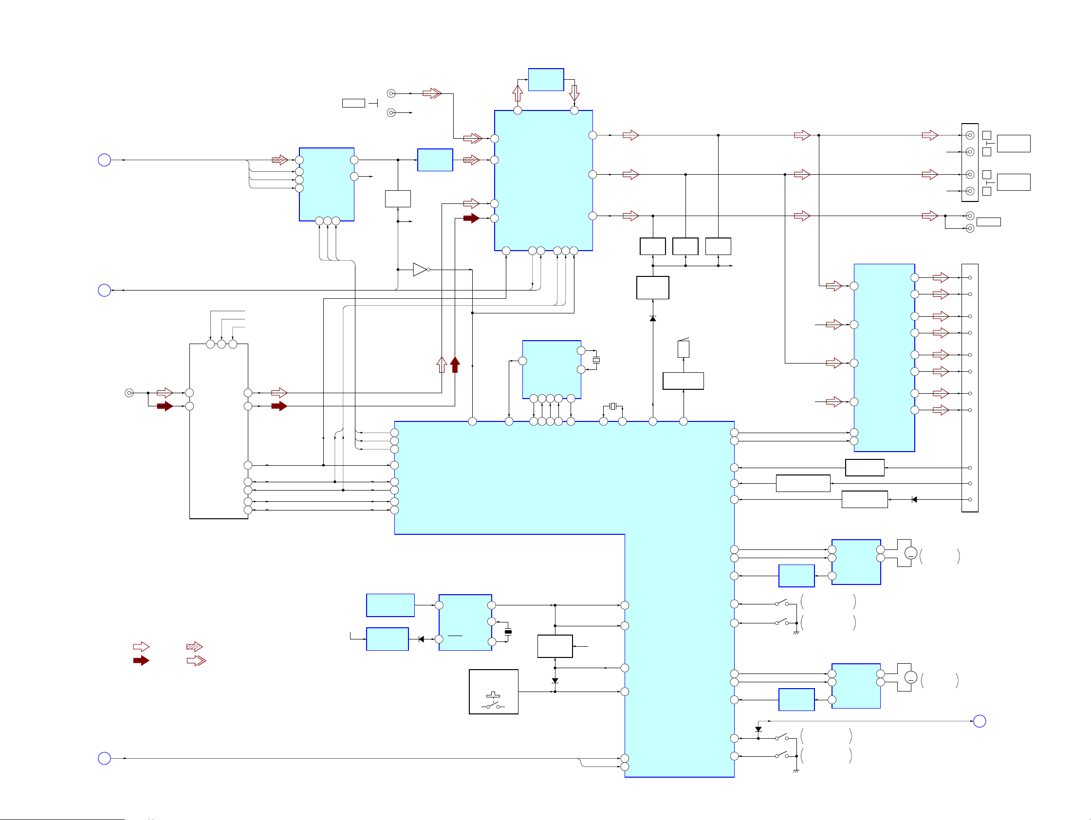
MEX-1HD
6-3. BLOCK DIAGRAM – AUDIO, SYSTEM Section –
D/A CONVERTER
SDO, MCLK,
(Page 27)
(Page 28)
(Page 27)
LRCK, BCLK
C
SA_DATA, SA_CLK,
D_MUTING
K
(FM/AM ANTENNA IN)
• R-ch is omitted due to same as L-ch.
• SIGNAL PATH
XMS_DET0,
XMS_DET1
D
11
5
B/U 5V
VCC-8.5V
FM-ANT
2
AM-ANT
1
AM-DET
FM/AM
TUNER PACK
TUX101
S-METER
EEPROMSDA
EEPROMSCL
: FM : CD PLAY
: AM
: BUS AUDIO IN
16
TUNER 5V
MPX
SDA
SCL
BU5V
TUN8V
TUN5V
10
8
14
12
13
17
18
SDO
MCLK
LRCK
BCLK
2DIN VOUTL
16 SCK
3LRCK
1BCK
IC371
DAC_CLK
DAC_SO
XCS14CLK13DATA
15
DAC_CS
ICK
IDA
AUX IN
7
8VOUTR
ILL10V
(L)
(R)
R-CH
MUTING
DAC_SO
DAC_CLK
DAC_CS
REMOTE CONTROL
RECEIVER
D904, IC902
RESET SIGNAL
GENERATOR
IC904
Q374
D_MUTING
DAC_SO
21
22
DAC_CLK
29
XDAC_CS
53
VM
70
I2CSIO
71
I2CCKO
10
E2SIO
E2CKO
11
R-CH
LOW-PASS
R-CH
Q306
D907
FILTER
IC372
CONTROLLER
SIRCS
IN
RESET
6
SIRCS
IC903
31
XS_MUTING
SIRCS
OUT
XIN
XOUT
LSW901, S3,
S901 – 910
179
3
4
4
40
12
9
38
ACOUTL
AUX-L
CDL
ELECTRICAL VOLUME
MPX1
AM/MPX2
MPIN
14
1 32KOUT
74
X0A
X900
4MHz
LOW-PASS
FILTER
IC302
ACINL
INPUT SELECT,
IC301
OUTSW
SACLK
SAOUT
21
23
SA_CLK
SA_DATA
ICK
IDA
REAL TIME CLOCK
IC502
OSCOUT
OSCIN
SCLK7CE6XINTR
SO
2
4SI3
25
26
27
28
RTC_SI
RTC_CS
RTC_SO
RTC_CLK
SYSTEM CONTROLLER
IC501 (2/3)
KEY ACTIVE
SWITCH
Q521
D505
33
OUTLF
OUTLR
XSM20SCL19SDA
17
76
XRTC_INT
28
27
24
8
9
BU5V
XMS_DET0
XMS_DET1
X502
32.768kHz
X501
3.68MHz
92 93
X0
X1
24
72
80
46
30
36
MUTING
Q305
MUTING
CONTROL
Q351, 352
SIRCS
KEYACK
XADON
KEYIN0
XMS_DET0
XMS_DET1
D311
BUZZER DRIVE
5
LINE_MUTING
MUTING
Q303
BZ361
Q361
15
XAMP_MUTING
BEEP
XFPCLOSE_END
XFPOPEN_END
XTR_CLOSE_END
XTR_OPEN_END
MUTING
Q301
AMP_ON
TELATT
XACC_IN
XILL_IN
FP_M+
FP_M–
FP_I_DET
TRAY_M+
TRAY_M–
TR_I_DET
100
55
16
81
95
98
97
49
99
61
62
51
59
58
R-CH
9
R-CH
(FRONT)
R-CH
(REAR)
ACCESSORY CHECK
Q202
OVER LOAD
DETECT
IC402
PANEL CLOSE-END
DETECT
PANEL OPEN-END
DETECT
OVER LOAD
DETECT
IC412
S1D6
TRAY CLOSE-END
S2
DETECT
TRAY OPEN-END
DETECT
POWER AMP
IC304
FL-IN
11
FR-IN
12
15
RL-IN
14
RR-IN
22
XMUTING
4
STBY
LEVEL SHIFT
Q201
DIMMER DETECT
Q203
FRONT PANEL
OPEN/CLOSE MOTOR DRIVE
IC411
IC411
9
OUT1FIN
7
OUT2RIN
9
OUT1FIN
7
OUT2RIN
3
4
6
PGND
TRAY OPEN/CLOSE
MOTOR DRIVE
3
4
6
PGND
FL–
FR+
FR–
RL+
RL–
RR+
RR–
FL+
9
7
5
3
17
19
21
23
D206
M
M
R-CH
(FRONT)
R-CH
(REAR)
M601
FRONT PANEL
OPEN/CLOSE
M103
TRAY
OPEN/CLOSE
XCLOSE_END
CNJ302
CNJ201
(1/2)
2
1
3
4
10
9
11
12
14
7
15
L
R
L
R
SUB OUT
FL+
FL–
FR+
FR–
RL+
RL–
RR+
RR–
ATT
ACC
ILL
(Page 27)
A
AUDIO OUT
FRONT
AUDIO OUT
REAR
2929
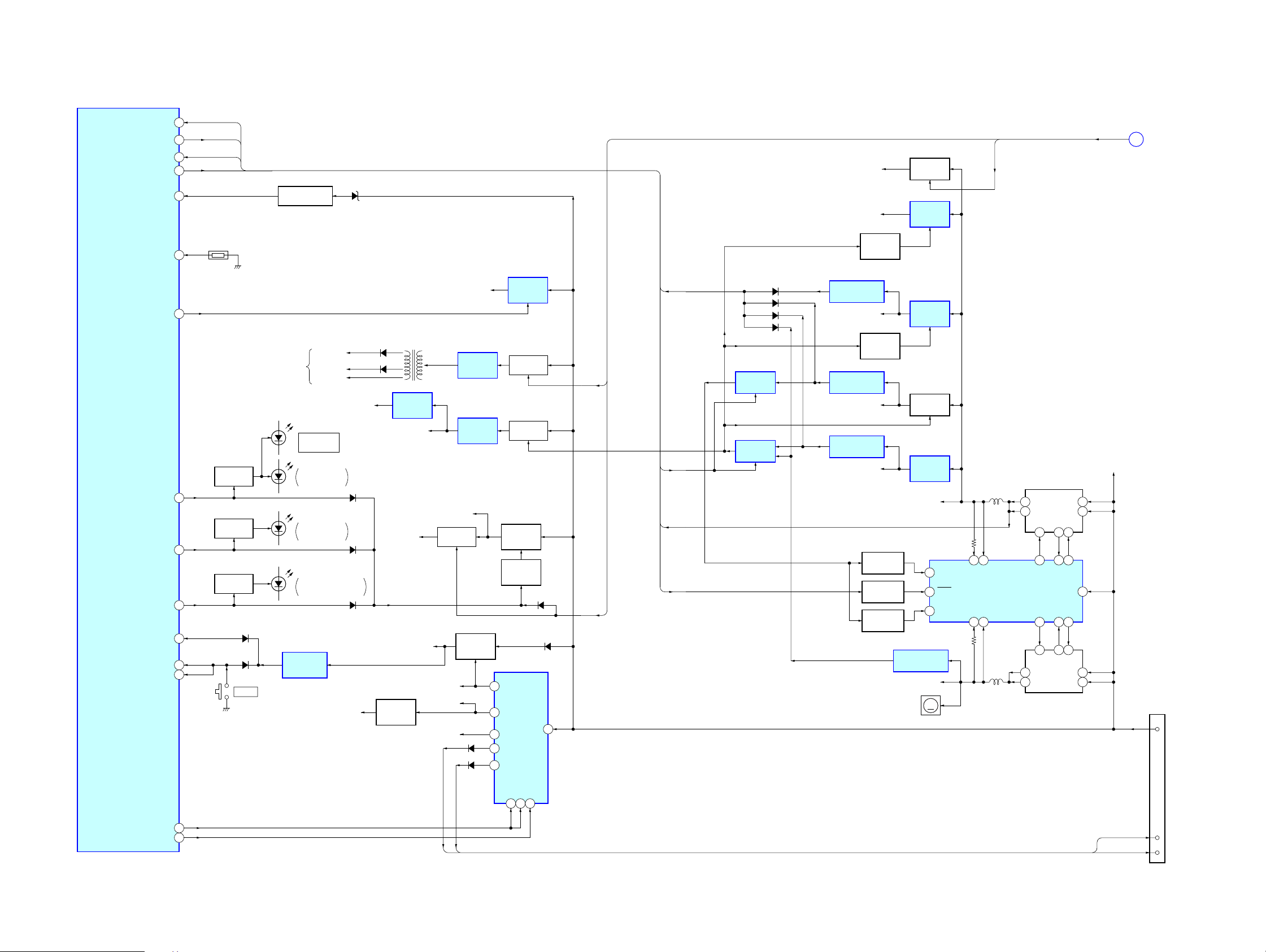
MEX-1HD
6-4. BLOCK DIAGRAM – POWER SUPPLY Section –
XPDOWN
MAIN_PON
FSW_IN
FSW_SFT
MOTOR_ON
SYSTEM CONTROLLER
IC501 (3/3)
MS_LED
78
120
65
37
77BU_IN
47TEMP
101
60TRAY_LED
57DOOR_IND
111
85RAMBU
90XRST
86HSTX
XPDOWN
MAIN_PON
FSW_IN
FSW_SFT
THP501
LED DRIVE
LED DRIVE
LED DRIVE
Q530
Q531
Q529
D521
D522
RESET
BATTERY CHECK
Q231 – 233
TO FL900
OPEN/CLOSE
ILLUMINATION
ILLUMINATION
MEMORY STICK SLOT
RESET SIGNAL
GENERATOR
IC503
D231, 232
FL+48V
F (+) 4.3V
F (–) 1.0V
D1
Z
D5
FRONT
(TRAY)
D2, 3
TRAY
D4203, 4204
ILLUMINATION
TUN5V
DAC5V
D851-1
D851-2
D852-1
D806
D804, 805
REGULATOR
INVERTER
TRANSFORMER
T800
+3.3V
REGULATOR
IC3005
DA5V
ILL10V
BU5V
+5V
Q206
MOTOR+9V, DRV+9V
SWITCHING
REGULATOR
IC800
+5V
REGULATOR
IC391
LED10V
B+ SWITCH
Q855
+5V
REGULATOR
Q204
BU5.6V
TUN8V
COM8V
D221
D222
REGULATOR
REGULATOR
CONTROL
REGULATOR
5 BU+B
11 FM8V
9 COM8V
8 ANT+B
6
AMP+B
+9V
REGULATOR
IC401
B+ SWITCH
Q801, 802
B+ SWITCH
Q372, 373
+10V
Q851
Q852
D852-2
IC201
VCC
D210
FL_ON, ILL_ON,
FLD_ON
3 2
SNS1–
SNS2–
13 14
FLD_ON
SNS1+
SWITCHING
REGULATOR
SNS2+
IC701
5
D2
D2
6
23 26 27
19 17 16
5
D2
D2
6
DRIVER
IC705
G2
4 1
BG1BG2
4 1 2
G2
DRIVER
IC704
S1
SW1SW2
S1
2
VIN
BATT
D1
7
8
D1
G1
TG1TG2
24
G1
D1
7
8
D1
FL_3.3V
DSP1.8V
REGULATOR
ON/OFF
Q3000
XPDOWN
FL_ON
MAIN_PON
FSW_IN
FSW_SFT
ILL_ON
7
D512
D513
D511
D514
SWITCHING
IC711
SWITCHING
IC712
VOLTAGE DETECT
IC713
D1.9V
REGULATOR
ON/OFF
VOLTAGE DETECT
IC708
D3.3V (A3.3V)
VOLTAGE DETECT
IC709
MS1.8V
LEVEL SHIFT
Q704, 707
LEVEL SHIFT
LEVEL SHIFT
Q706, 713
Q708
Q705
B+ SWITCH
Q853, 854
+1.8V
REGULATOR
IC3001
+1.9V
REGULATOR
IC702
B+ SWITCH
Q710, 717
+1.8V
REGULATOR
IC703
SYS3.3V
1
5 FREQ
15
VOLTAGE DETECT
IC707
D5V (A5V, S5V)
M501
M
(FAN)
RUN/SS1
RUN/SS2
J
(Page 28)
CNJ201
(2/2)
16
B+
TUNON
STB2MODE2
MODE1
4
3
AMP REM
114
83PWON
ANT REM
ANT REM
AMP REM
5
ANT-R
6
AMP-R
3030
 Loading...