

Page 1
Multiformat
Engine Unit
4-098-710-15 (1)
Operating Instructions
MEU-WX1
© 2003 Sony Corporation
Page 2

English
Owner’s Record
The model and serial numbers are located at the bottom.
Record these numbers in the spaces provided below.
Refer to these numbers whenever you call upon your
Sony dealer regarding this product.
Model No. ____________________
Serial No. ____________________
WARNING
To prevent fire or shock hazard, do not expose the unit to
rain or moisture.
Dangerously high voltages are present inside the unit.
Do not open the cabinet. Refer servicing to qualified
personnel only.
In the event of a malfunction or when maintenance is
necessary, consult an authorized Sony dealer.
This unit contains substances which can pollute the
environment if disposed carelessly.
Please contact our nearest representative office or your
local environmental office in case of disposal of this
unit.
For the customers in Europe
This product with the CE marking complies with the
EMC Directive (89/336/EEC) issued by the
Commission of the European Community.
Compliance with this directive implies conformity to the
following European standards:
• EN60950: Product Safety
• EN55103-1: Electromagnetic Interference (Emission)
• EN55103-2: Electromagnetic Susceptibility
(Immunity)
This product is intended for use in the following
Electromagnetic Environment(s):
E4 (controlled EMC environment, ex. TV studio).
For the Customers in the USA
This equipment has been tested and found to comply
with the limits for a Class A digital device, pursuant to
Part 15 of the FCC Rules. These limits are designed to
provide reasonable protection against harmful
interference when the equipment is operated in a
commercial environment. This equipment generates,
uses, and can radiate radio frequency energy and, if not
installed and used in accordance with the instruction
manual, may cause harmful interference to radio
communications. Operation of this equipment in a
residential area is likely to cause harmful interference in
which case the user will be required to correct the
interference at his own expense.
WARNING
THIS APPARATUS MUST BE EARTHED.
You are cautioned that any changes or modifications not
expressly approved in this manual could void your
authority to operate this equipment.
The shielded interface cable recommended in this
manual must be used with this equipment in order to
comply with the limits for a digital device pursuant to
Subpart B of Part 15 of FCC Rules.
For customers in Canada
This Class A digital apparatus complies with Canadian
ICES-003.
Pour les utilisateurs au Canada
Cet appareil numérique de la classe A est conforme à la
norme NMB-003 du Canada.
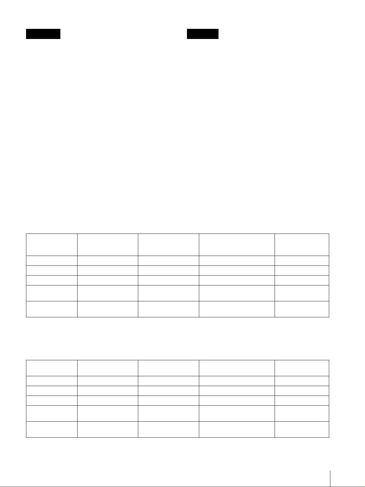
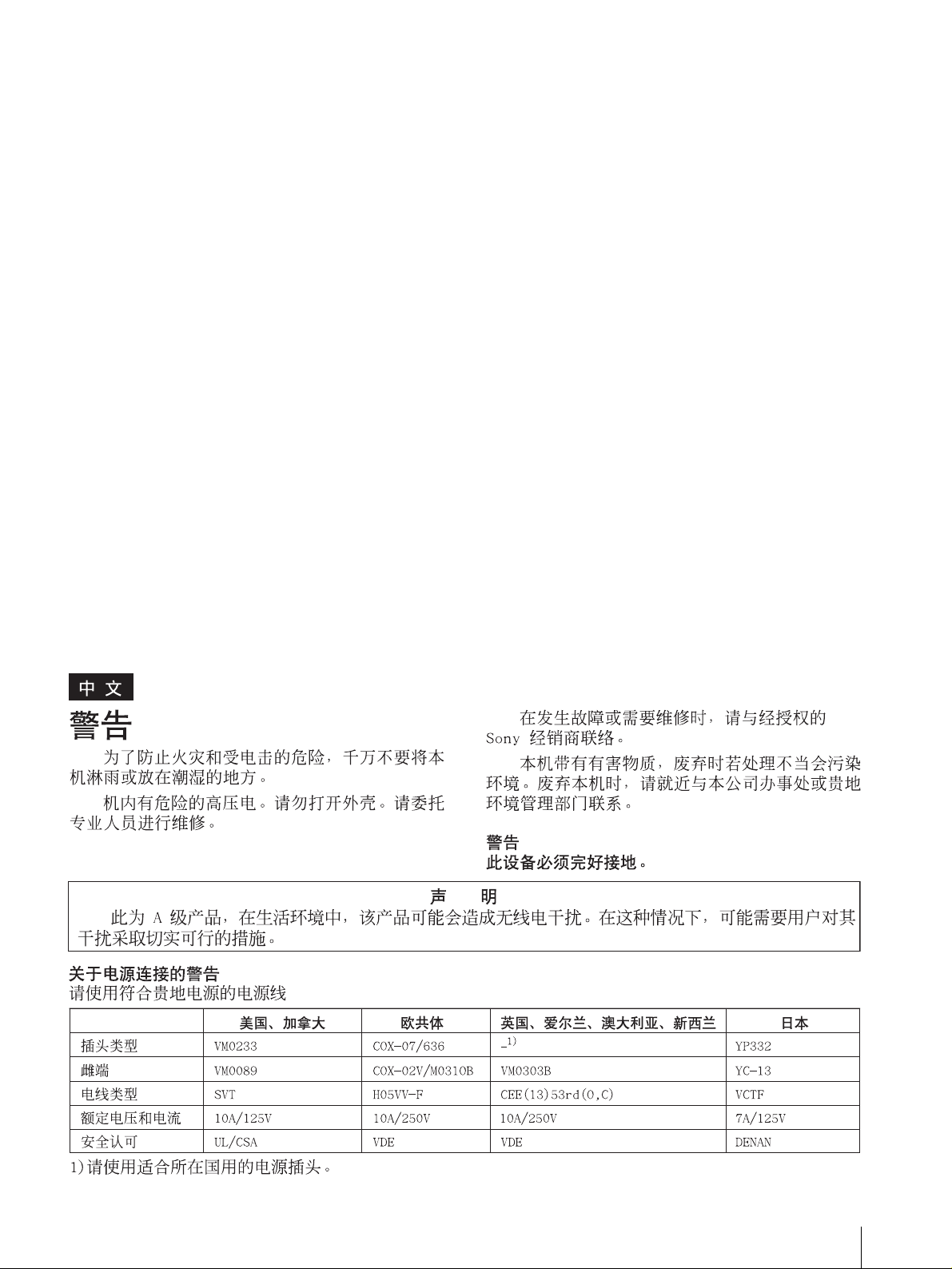
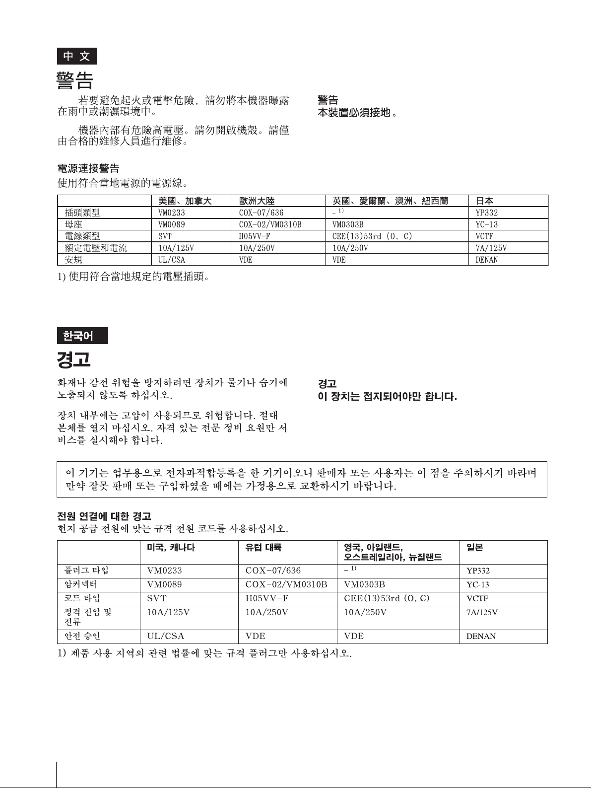
Warning on power connection
Use a proper power cord for your local power supply.
The United States,
Canada
Plug type VM0233 COX-07/636
Female end VM0089 COX-02/VM0310B VM0303B YC-13
Cord type SVT H05VV-F CEE(13)53rd (O, C) VCTF
Rated Voltage &
Current
Safety approval UL/CSA VDE VDE DENAN
10A/125V 10A/250V 10A/250V 7A/125V
Continental Europe UK, Ireland, Australia,
New Zealand
_ 1)
Japan
YP332
1) Use an appropriate rating plug which is applied to local regulations.
2
Page 3
Français Deutsch
AVERTISSEMENT
Afin d'éviter tout risque d'incendie ou d'électrocution, ne
pas exposer cet appareil à la pluie ou à l'humidité.
Des courants de hautes tensions dangereuses sont
présents à l'intérieur de cet appareil. Ne pas ouvrir le
coffret. Se reporter à un personnel qualifié uniquement.
Dans le cas d'une défaillance ou de nécessité d'entretien,
consulter un revendeur Sony autorisé.
Cet appareil contient des substances susceptibles de
causer une pllution de l'environnement si elles sont
éliminées de façon non conforme. Consultez votre
bureau local de préservation de l'environnement pour
savoir comment vous débarrasser de cet appareil.
AVERTISSEMENT
CET APPAREIL DOIT ETRE RELIE A LA TERRE.
Pour les utilisateurs au Canada
Cet appareil numérique de la classe A est conforme à la
WARNUNG
Um Feuergefahr und die Gefahr eines elektrischen
Schlages zu vermeiden, darf das Gerät weder Regen
noch Feuchtigkeit ausgesetzt werden.
Im Inneren des Geräts liegt gefährliche Hochspannung
an. Öffnen Sie niemals das Gehäuse, und überlassen Sie
Wartungsarbeiten stets nur einem Fachmann.
Sollten am Gerät Probleme auftreten oder eine Wartung
erforderlich werden, wenden Sie sich an einen
autorisierten Sony -Händler.
Dieses Gerät enthält Substanzen, die bei unsachgemäßer
Entsorgung die Umwelt belasten. Bitten wenden Sie
sich an unsere nächste Niederlassung oder an Ihr
Umweltschutzamt, wenn Sie das Gerät entsorgen
wollen.
WARNUNG
DIESES GERÄT MUSS GEERDET WERDEN.
norme NMB-003 du Canada.
Avertissement concernant le raccordement au secteur
Utilisez un cordon d'alimentation adapté à la tension secteur.
Etats-Unis, Canada Europe
continentale
Type de fiche VM0233 COX-07/636
Extrémité femelle VM0089 COX-02/VM0310B VM0303B YC-13
Type de cordon SVT H05VV-F CEE(13)53rd (O, C) VCTF
Intensité et tension
nominales
Certification de
sécurité
10A/125V 10A/250V 10A/250V 7A/125V
UL/CSA VDE VDE DENAN
Royaume-Uni, Irlande,
Australie, NouvelleZélande
_ 1)
Japan
YP332
1) Utilisez une fiche présentant les valeurs nominales appropriées et conforme à la réglementation locale en vigueur.
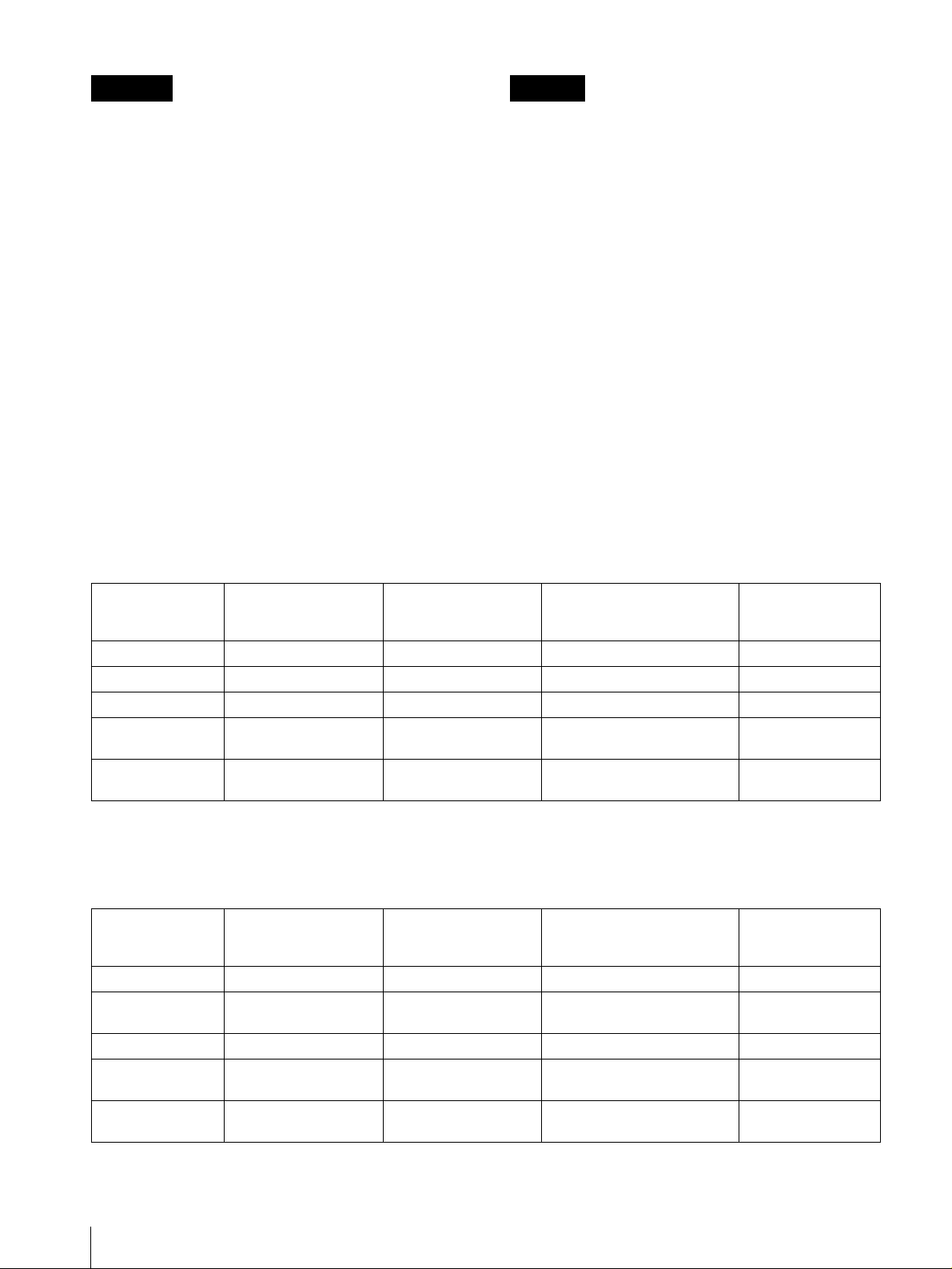
Warnhinweis zum Netzanschluss
Verwenden Sie ein für die Stromversorgung in Ihrem Land geeignetes Netzkabel.
USA, Kanada Kontinental-Europa Großbritannien, Irland,
Steckertyp VM0233 COX-07/636
Buchse VM0089 COX-02/VM0310B VM0303B YC-13
Kabeltyp SVT H05VV-F CEE(13)53rd (O, C) VCTF
Nennspannung &
Stromstärke
Sicherheitszertifizi
erung
10A/125V 10A/250V 10A/250V 7A/125V
UL/CSA VDE VDE DENAN
Australien, Neuseeland
_ 1)
Japan
YP332
1) Verwenden Sie einen geeigneten Netzstecker, der die örtlichen Bestimmungen erfüllt.
3
Page 4
Español Italiano
ADVERTENCIA
ATTENZIONE
Per evitare incendi o cortocircuiti, l'apparecchio non
Para evitar incendios o el riesgo de electrocución, no
deve essere esposto alla pioggia o all'umidità.
exponga la unidad a la lluvia ni a la humedad.
All'interno del televisore sono presenti tensioni
Dentro de la unidad existen altas tensiones peligrosas.
No la abra. En caso de avería, solicite los servicios de
personal cualificado.
En caso de mal funcionamiento o cuando sea necesario
el servicio de mantenimiento, consulte a su proveedor
Sony.
pericolosamente alte. Non aprire l'apparecchio. Per le
riparazioni, rivolgersi esclusivamente a personale
specializzato.
Nel caso di malfunzionamenti o di necessarie
riparazioni dell'apparecchio, consultare un rivenditore
autorizzato Sony.
Questo apparecchio contiene sostanze che possono
Esta unidad contiene sustancias que pueden contaminar
el medio ambiente si no se desecha adecuadamente.
Póngase en contacto con nuestro departamento de
representatión más próximo o con el departamento local
de medio ambiente cuando vaya a desechar esta unidad.
ADVERTENCIA
ESTE APARATO DEBE CONECTARSE A TIERRA.
inquinare l'amibiente se non vengono smaltite con le
dovute cautele. Per informazioni sulle normative in caso
di smaltimento di questo apparecchio, si prega di
contattare il nostro rappresentatnte locale o il centro di
informazioni ambientali di zona.
AVVERTENZA
QUESTO APPARECCHIO DEVE ESSERE
COLLEGATO A MASSA.
Advertencia sobre la conexión de alimentación
Utilice un cable de alimentación adecuado al suministro eléctrico loca.
Estados Unidos y
Canadá
Tipo de enchufe VM0233 COX-07/636
Extremo hembra VM0089 COX-02/VM0310B VM0303B YC-13
Tipo de cable SVT H05VV-F CEE(13)53rd (O, C) VCTF
Corriente y tensión
nominal
Aprobación de
seguridad
10A/125V 10A/250V 10A/250V 7A/125V
UL/CSA VDE VDE DENAN
Europa continental Reino Unido, Irlanda,
Australia y Nueva
Zelanda
_ 1)
Japón
YP332
1) Utilice un enchufe de valor nominal adecuado que cumpla con la normativa local.
Avvertenza sul collegamento dell'alimentazione
Utilizzare un cavo di alimentazione adeguato all'alimentazione del Paese in cui ci si trova.
Stati Uniti, Canada Europa
Tipo di spina VM0233 COX-07/636
Terminale
femmina
Tipo di cavo SVT H05VV-F CEE(13)53rd (O, C) VCTF
Tensione e corrente
nominale
Approvazione di
sicurezza
VM0089 COX-02/VM0310B VM0303B YC-13
10A/125V 10A/250V 10A/250V 7A/125V
UL/CSA VDE VDE DENAN
continentale
Regno Unito, Irlanda,
Australia, Nuova Zelanda
Giappone
_ 1)
Japan
YP332
1) Utilizzare una presa con voltaggio adeguato conforme alle normative locali.
4
Page 5
Pour les clients européens
Ce produit portant la marque CE est conforme à la fois
à la Directive sur la compatibilité électromagnétique
(EMC) (89/336/CEE) et à la Directive sur les basses
tensions (73/23/CEE) émises par la Commission de la
Communauté européenne.
La conformité à ces directives implique la conformité
aux normes européennes suivantes:
• EN60950: Sécurité des produits
• EN55103-1: Interférences électromagnétiques
(émission)
• EN55103-2: Sensibilité électromagnétique
(immunité)
Ce produit est prévu pour être utilisé dans
l'environnement électromagnétique suivant:
E4 (environnement EMC contrôlé ex. studio de
télévision).
Für Kunden in Europa
Dieses Produkt besitzt die CE-Kennzeichnung Und
erfüllt die EMV-Richtlinie (89/336/EWG) sowie die
Niederspannungsrichtlinie (73/23/EWG) der EGKommission.
Angewandte Normen:
• EN60950: Sicherheitsbestimmungen
• EN55103-1: Elektromagnetische Verträglichkeit
(Störaussendung)
• EN55103-2: Elektromagnetische Verträglichkeit
(Störfestigkeit),
für die folgenden elektromagnetischen Umgebungen:
E4 (kontrollierter EMV-Bereich, z.B. Fernsehstudio)
Per i clienti in Europa
Questo prodotto recante il marchio CE è conforme sia
alla direttiva sulla compatibilità elettromagnetica
(EMC) (89/336/CEE) che alla direttiva sulle basse
tensioni (73/23/CEE) emesse dalla Commissione della
Comunità Europea.
La conformità a queste direttive implica la conformità
alle seguenti normative europee:
• EN60950: Sicurezza dei prodotti
• EN55103-1: Interferenza elettromagnetica (Emissione)
• EN55103-2: Sensibilità ai disturbi elettromagnetici
(Immunità)
Questo prodotto è destinato all’uso nei seguenti
ambienti elettromagnetici: E4 (ambienti EMC
controllati, ad esempio studi televisivi).
Para los usuarios en Europa
Este producto con la marca CE cumple con las
Directivas EMC (89/336/CEE) y de Baja Tensión (73/
23/CEE) emitidas por la Comisión de la Comunidad
Europea.
El cumplimiento de estas directivas implica la
conformidad con los siguientes estándares europeos:
• EN60950: Seguridad del producto
• EN55103-1: Interferencias electromagnéticas
(Emisión)
• EN55103-2: Susceptibilidad electromagnética
(Inmunidad)
Este producto está destinado a emplearse en los
siguientes entornos electromagnéticos:
E4 (entornos con control EMC, por ejemplo, estudios de
TV).
5
Page 6
6
Page 7

Table of Contents
Precaution ..............................................................8
On Safety ............................................................ 8
On Installation .................................................... 8
On Cleaning ........................................................ 8
On Repacking ..................................................... 8
On Mounting on a Rack .....................................8
On Fan Error ....................................................... 8
Features ..................................................................8
Location and Function of Parts and Controls .. 10
Front Panel .......................................................10
Input signals and adjustable/setting items ........ 12
Rear Panel ........................................................13
Installing to the Rack ..........................................14
Connections ..........................................................15
To Connect an LCD Monitor ............................ 15
To Connect the AC Power Cord .......................15
Attaching the Input Adaptor .............................. 16
Selecting the Default Settings ............................. 16
Selecting the Menu Language ............................ 18
Using the Menu ....................................................19
Adjustment Using the Menus ............................. 20
Items ................................................................. 20
Adjusting and Changing the Settings ............... 21
STATUS menu............................................ 21
COLOR TEMP/BAL menu ........................ 21
USER CONTROL menu ............................. 22
USER CONFIG menu ................................. 25
REMOTE PARALLEL menu ..................... 28
OPTION CONFIG menu ............................ 28
KEY INHIBIT menu ................................... 28
Troubleshooting ...................................................29
Specifications ........................................................29
Dimensions ........................................................... 32
7
Page 8

Precaution
On Safety
• Operate the unit only with a power source as specified
in the “Specifications” section.
• A nameplate indicating operating voltage, power
consumption, etc., is located on the bottom panel.
• Should any solid object or liquid fall into the cabinet,
unplug the unit and have it checked by qualified
personnel before operating it any further.
• Do not drop or place heavy objects on the power cord.
If the power cord is damaged, turn off the power
immediately. It is dangerous to use the unit with a
damaged power cord.
• Unplug the unit from the wall outlet if it is not to be
used for several days or more.
• Disconnect the power cord from the AC outlet by
grasping the plug, not by pulling the cord.
• The socket-outlet shall be installed near the equipment
and shall be easily accessible.
On Mounting on a Rack
Leave 1U space empty above and below the monitor to
ensure adequate air circulation or install a fan to
maintain the monitor’s performance.
If you have any questions about this unit, contact your
authorized Sony dealer.
On Fan Error
The fan for cooling the unit is built in. When the “Fan
error (MEU)” or “Fan error (LMD)” message is
displayed, turn off the power and contact an authorized
Sony dealer.
Features
The MEU-WX1 is a Multiformat Engine Unit which is
used with an LCD monitor for professional use.
On Installation
• Allow adequate air circulation to prevent internal heat
build-up.
Do not place the unit on surfaces (rugs, blankets, etc.)
or near materials (curtains, draperies) that may block
the ventilation holes.
• Do not install the unit in a location near heat sources
such as radiators or air ducts, or in a place subject to
direct sunlight, excessive dust, mechanical vibration
or shock.
On Cleaning
To keep the unit looking brand-new, periodically clean it
with a mild detergent solution. Never use strong solvents
such as thinner or benzine, or abrasive cleansers since
they will damage the cabinet. As a safety precaution,
unplug the unit before cleaning it.
On Repacking
Do not throw away the carton and packing materials.
They make an ideal container which to transport the
unit.
Picture
I/P converter for motion detection
Sony original image processing circuitry has been newly
developed. Normal video signals, computer graphics
and film-originated sources are processed through an
adaptive frame processing and image conversion such as
2-3 pull down function, etc., and a natural, precise image
is displayed.
Full digital image processing circuitry
As well as digital signals, all signals including analog
signals are converted into digital signals without any
deterioration in the pictures via a full digital image
processing circuitry.
Two color system available
The monitor can display NTSC and PAL signals by
connecting this unit. The appropriate color system is
selected automatically.
Auto chroma phase function
The chroma and phase of the decoder are automatically
adjusted with the auto chroma phase function.
Blue only mode
In the blue only mode, an apparent monochrome display
is obtained with all three of the R/G/B cathodes driven
with a blue signal. This facilitates color saturation and
phase adjustments and observation of VCR noise.
8
Precaution / Features
Page 9

Input
Analog RGB/component input connectors
Analog RGB or component (Y, P
video equipment can be input through these connectors.
Y/C input connectors
The video signal, split into the luminance signal (Y) and
the chrominance signal (C), can be input through this
connector.
Expandable input capability
You can easily expand the input capability by installing
an input adaptor (not supplied) in the input option slot in
the rear of the unit.
B, PR) signals from
Scan setting
You can set the display size to 0% or 5% over scan
mode.
H/V delay mode
The horizontal and vertical sync signals can be
monitored simultaneously in the H/V delay mode.
On-screen menus
You can set the appropriate settings according to the
connected system by using the on-screen menus.
EIA 19-inch rack mount bracket available
The monitor may be mounted on an EIA-standard 19inch rack, using the supplied mounting bracket.
External sync input
When the EXT SYNC button is in the on position, the
unit can be operated on the sync signal supplied from an
external sync generator.
Automatic termination (connector with mark
only)
The input connector is terminated internally at 75 ohms
when nothing has been connected to the output
connector. If a cable is connected to the output
connector, the internal terminal is automatically released
and the signals input to the input connector are output to
the output connector (loop-through).
Accepts analog computer input signals
The built-in scan converter enables the monitor to detect
VGA, SVGA, XGA, WXGA and SXGA signals, and
display them on the screen.
We recommend displaying an image in XGA or WXGA
signals.
Functions
APA (Auto Pixel Alignment) function
You can display pictures from the computer in the
appropriate size by simply pressing the APA button.
Key inhibit function
You can inhibit a key, function to prevent misoperation.
Select language display
You can select from seven display languages English,
German, French, Italian, Spanish, Japanese and
Chinese.
External remote control function
You can directly select the input signal, aspect, etc., by
operating the equipment connected to the PARALLEL
REMOTE terminal.
Select color temperature and gamma mode
You can select the color temperature from among two
(high and low) settings and gamma mode from among
five settings. You can also adjust the color temperature
to the appropriate setting.
Aspect setting
You can set the monitor to 4:3 or 16:9 display mode
according to the input video signal.
Various markers
Displays frame boundaries such as the center marker,
safe area marker, etc. and supports the various film
aspect ratios.
Features
9
Page 10
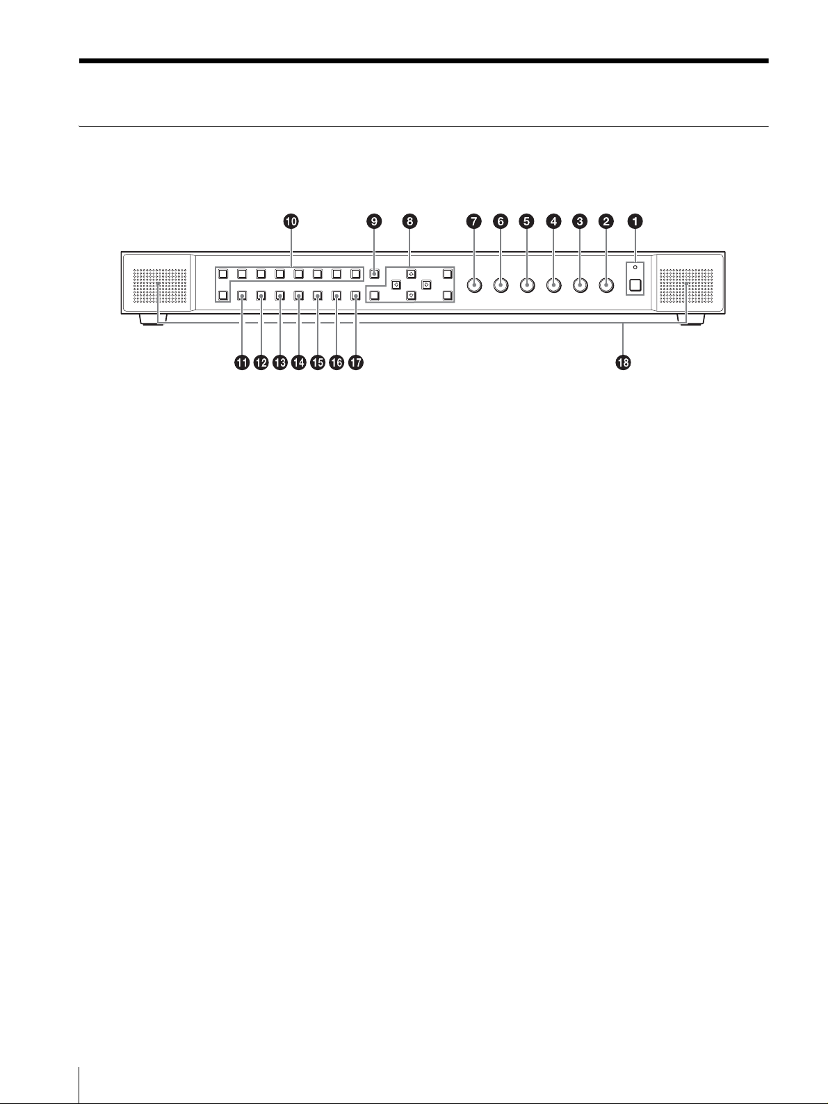
Location and Function of Parts and Controls
Front Panel
a POWER switch and indicator
Press to turn on the power. The indicator turns on. Press
again to turn off the power.
b VOLUME control
Turn the control clockwise to increase the volume or
counterclockwise to decrease it.
c CONTRAST control
Adjusts the picture contrast.
Turn the control clockwise to make the contrast higher
or counterclockwise to make it lower.
d PHASE control
Adjusts color tones.
Turn the control clockwise to make the skin tones
greenish or counterclockwise to make them purplish.
e CHROMA control
Adjusts the color intensity.
Turn the control clockwise to increase the color intensity
or counterclockwise to decrease it.
f BRIGHT (brightness) control
Adjusts the picture brightness.
Turn the control clockwise to increase the brightness or
counterclockwise to decrease it.
g APERTURE control
Adjusts the picture sharpness.
Turn the control clockwise to increase the sharpness or
counterclockwise to decrease it.
h Menu operation buttons
Displays or sets the on-screen menu.
M/m/</, (arrow) buttons
Select the menu or make various adjustments.
MENU button
Press to display the on-screen menu.
Press again to clear the menu.
RESET button
Resets the value of an item back to the previous
value. This button functions when the menu item is
adjusted (displayed) on the screen.
ENTER button
Press to confirm a selected item on the menu.
i EXT SYNC (external sync) button
Press to operate the unit on an external sync signal
through the EXT SYNC IN connector.
The EXT SYNC button works when the component/
RGB signals are input.
j Input select buttons
Press the button according to the connected terminal.
A-1, A-2, B-1 and B-2 buttons are used when an
optional input adaptor has been installed in the option
slot.
COMPOSITE button: to monitor the signal through
the video input (composite) connectors.
10
Location and Function of Parts and Controls
Y/C button: to monitor the signal through the video
input (Y/C) connectors.
Page 11

RGB button: to monitor the signal through the video
input (RGB) connectors.
COMPONENT button: to monitor the signal
through the video input (component) connectors.
A-1 button: to monitor the signal from option slot
A-1.
A-2 button: to monitor the signal from option slot
A-2.
B-1 button: to monitor the signal from option slot
B-1.
B-2 button: to monitor the signal from option slot
B-2.
COMPUTER button: to monitor the signal through
the COMPUTER SIGNAL IN connector.
k APA (Auto Pixel Alignment) button
Adjusts the picture automatically to maximum clarity
while a signal is input from a computer. For finer
according to the input signal, see “DOT PHASE” on
page 23.
The operation is stopped by pressing the MENU or
RESET button during the APA operation. When the
menu screen is displayed, the APA does not function.
l SCAN select button
You can change the scan size of the picture. When you
press the button, the scan size is changed to normal scan
(5% over scan), 0% scan, FULL or ZOOM set on the
menu (see page 26).
n MARKER button
When the button is pressed, an area marker is displayed.
Set the safety area size in the menu screen.
o BLUE ONLY button
Press this button to eliminate the red and green signals.
Only blue signal is displayed as an apparent
monochrome picture on the screen. This facilitates
“chroma” and “phase” adjustments and observation of
VCR noise.
p MONO button
Press this button to display a monochrome picture.
When the buttons is pressed again, the monitor switches
automatically to color mode.
q HV DELAY button
Press to observe the horizontal and vertical sync signals
at the same time.
r Speakers
The audio signal which is selected by the input select
button on the front panel is output.
When an analog video signal is input, the signal which
is set in the USER CONFIG menu is output (see page 14
and 25).
When an input adaptor is attached, the channel which is
set in the OPTION CONFIG menu is output (see
page 28).
The audio signals from the speakers are output from the
AUDIO MONITOR OUT connector on the rear (see
page 14).
m ASPECT select button
Sets the aspect ratio of the picture, 4:3 or 16:9.
Note
When a 16:9 signal is displayed, black bars appear in the
upper and lower positions of the display because the
screen size is 15:9. This is not a malfunction. (See
SCAN on page 26/27.)
Location and Function of Parts and Controls
11
Page 12

Input signals and adjustable/
setting items
Input signal
Item Video, Y/C B & W Component RGB SDI DV*
CONTRAST*
BRIGHT*
CHROMA*
PHASE*
APERTURE
COLOR TEMP
AUTO CHROMA/
PHASE
ACC
CTI
V SHARPNESS*
MATRIX*
COMP LEVEL*
NTSC SETUP
GAMMA
SCAN
ASPECT
MARKER
BLUE ONLY
MONO
HV DELAY
APA
SIZE H
SHIFT
DOT PHASE
POWER SAVING
PIC DELAY MIN
1
1
1
1
3
SD HD SD HD D1*
a a aaaaaaa a
a a aaaaaaa a
a
a (NTSC)
aaaa
a a aaaaaaa a
a
a
a
2
aaa×a
×
Ч ЧЧЧЧЧЧЧ ×
×
Ч ЧЧЧЧЧЧЧ ×
×
××
4
××
a (NTSC)
a a aaaaaaa a
a a aaaaaaa
aaa×a
a a aaaaaaa
a
a
a a aaaaaaa
a
(480/60I)
×
×
aa
××
××
aa
a
ЧЧЧЧЧЧ ×
××
×
a ×
a
×××
ЧЧЧЧЧ ×
ЧЧЧЧЧЧЧ ×
×
aaaaaaa
aa
××
5
aaa
aaa
aaa ×
a
×
a
aaa
× Ч ЧЧЧЧЧЧЧ
× Ч ЧЧЧЧЧЧЧ
a a aaaaaaa a
× Ч ЧЧЧЧЧЧЧ
a a aaaaaaa
aaa×a
×
a
6
HD*
×
×× ×
×
×
a
a
a
7
Computer
×
×
×
×
×
×
×
×
×
a
a
a
a
×
a : Adjustable/can be set
× : Not adjustable/cannot be set
*1 Adjustment of SUB CONTROL is the same.
*2 When selecting “2” of PIC DELAY MIN in the
menu, this function does not work.
*3 When a component signal (480/60I or 480/60P) is
input and the COMP LEVEL is set to SMPTE, this
can be switchable.
12
Location and Function of Parts and Controls
*4 When a component signal (480/60I) is input, this
can be switchable.
*5 When a BKM-220D or BKM-243HS is attached.
*6 When a BKM-243HS is attached.
*7 When a BKM-255DV is attached.
Page 13

Rear Panel
a G/Y/COMPOSITE connector (BNC)*
Input connector for composite, component Y
(luminance) and G of RGB signals.
b B/P
Input connector for Y (luminance) of Y/C, P
B/S-Y connector (BNC)*
B (blue
color difference) of component signals and B of RGB
signals.
c R/P
Input connector for C (color) of Y/C, P
R/S-C connector (BNC)*
R (red color
difference) of component signals and R of RGB signals.
d EXT SYNC IN/OUT (external sync) connectors
(BNC)
Press the EXT SYNC button to use the sync signal
through this connector.
IN connector
When this unit operates on an external sync signal,
connect the reference signal from a sync generator
to this connector.
Note
When inputting a video signal with the jitters, etc.
the picture may be disturbed. We recommend using
the TBC (time base corrector).
OUT connector
Loop-through output of the IN connector. Connect
to the external sync input of video equipment to be
synchronized with this unit.
When the cable is connected to this connector, the
75-ohm termination of the input is automatically
released, and the signal input to the IN connector is
output from this connector.
e AUDIO IN connector (stereo mini jack)
Connect to the audio outputs of a VCR or to a audio
mixer.
f Optional input slot
An optional input adaptor can be attached according to
your requirements.
Press the A-1, A-2, B-1 or B-2 button to select the
signal.
g AC IN socket
Connect the supplied AC power cord.
h DC 12V IN connector (XLR)
Plug the DC 12V power supply to this connector to
provide power to the Multiformat Engine and monitor.
The operable monitor is as follows;
LMD-170W
i Loop-through output connectors (BNC)
The signals input to the input connectors (a, b and
c) are output here. Connect to the analog input
(composite/Y/C, analog component or analog RGB) of
equipment, according to the input signal.
* Composite and Y/C signals can be input at the same time. Convert a plug to the BNC type for connecting Y/C signals.
Component and RGB signals cannot be input at the same time because three connectors are used. If necessary, set
the output signals for the speakers on the front panel and AUDIO MONITOR OUT connector in the USER CONFIG
menu. For details, see page 25.
Location and Function of Parts and Controls
13
Page 14

j AUDIO MONITOR OUT connector (stereo
mini jack)
The audio signal which is selected by the input select
button on the front panel is output.
When an analog video signal is input, the signal which
is set in the USER CONFIG menu is output (see page 11
and 25).
When an input adaptor is attached, the channel which is
set in the OPTION CONFIG menu is output (see
page 28).
The audio signal from this connector is monitored on the
front speakers (see page 11).
k PARALLEL REMOTE terminal (modular
connector)
Forms a parallel switch and controls the Multiformat
Engine externally.
For details on the pin assignment and factory setting
function assigned to each pin, see page 30.
l COMPUTER SIGNAL IN connector (D-sub 15
pin, female)
Connect to the monitor output on a computer. Only the
computer signal can be input to this terminal.
Press the COMPUTER button to select the signal.
The Plug & Play function corresponds to DDC2B.
Installing to the Rack
1
Remove the four legs from the bottom.
2
Attach the mounting brackets with the supplied
screws. The brackets can be attached at two
positions.
m COMPUTER AUDIO connector (stereo mini
jack)
Connect to the audio output connector of the computer.
n Service terminal
This connector is for use by service personnel only.
o DISPLAY SIGNAL OUT connector
Connect a suitable monitor. Connect to the LCD
monitor by using the cable supplied with the LCD
monitor.
Specified monitor : LMD-170W/LMD-230W/LMD210/LMD-320W
p DISPLAY DC OUT connector (XLR, female)
Connect a suitable monitor. Connect to the LCD
monitor by using the cable supplied with the LCD
monitor.
Specified monitor : LMD-170W/LMD-230W/LMD210
Notes
• Do not connect a monitor other than the specified one.
• When LMD-170W is connected and the unit is used
with a DC power supply, the display IF cable SMF600 (optional) is not available.
3
Attach the unit to the rack.
When using the supplied mounting brackets for a
mobile application, it must be reinforced against a
shock, vibration and sway according to installation
circumstances.
14
Installing to the Rack
Page 15

Connections
To Connect an LCD Monitor
Before connecting the cable, disconnect the power cord.
Connect the DISPLAY SIGNAL OUT connector of this
unit and DISPLAY SIGNAL IN connector of the
monitor and DISPLAY DC OUT connector of this unit
and DISPLAY DC IN connector of the monitor using a
cable supplied with the monitor.
(When connecting LMD-320W, connect the DISPLAY
SIGNAL connector only.)
To Connect the AC Power Cord
Connect the supplied AC power cord as illustrated.
1
Plug the AC power cord into the AC IN socket on
the rear panel. Then, attach the AC plug holder
(supplied) to the AC power cord.
AC IN socket
AC cord
DISPLAY
DC OUT
SIGNAL IN
DISPLAY SIGNAL
OUT
DISPLAY DC INDISPLAY
2
AC plug holder (Supplied)
Slide the AC plug holder over the cord until it locks.
To remove the AC power cord
Pull out the AC plug holder while pressing the lock
levers.
Connections
15
Page 16

Attaching the Input
Selecting the Default
Adaptor
Before attaching the input adaptor, disconnect the power
cord.
Attach the input adaptor to the optional input slot after
removing the panel of the slot.
1
Remove the panel of the optional input slot.
2
Insert the input adaptor into the slot.
I
N
P
U
T
M
O
N
I
T
O
R
O
U
T
3
Tighten the screws.
I
N
P
U
T
M
O
N
I
T
O
R
O
U
T
Settings
When you turn on the unit for the first time after
purchasing it, select the area where you intend to use this
unit from among the options.
The default setting values for each area
3
5
4
3
1NORTH AMERICA Low BETA7.5
2LATIN AMERICA
PAL&PAL-N AREA
NTSC&PAL-M AREA OTHER AREA Low BETA7.5
3AFRICA AUSTRALASIA
EUROPE MIDDLE-EAST
4ASIA EXCEPT JAPAN
5JAPAN High
3
ARGENTINA Low
PARAGUAY Low
URUGUAY Low
NTSC AREA Low BETA7.5
PAL AREA Low
1
COLOR
TEMP
Low
2
COMP
LEVEL
N10/
SMPTE
N10/
SMPTE
N10/
SMPTE
N10/
SMPTE
N10/
SMPTE
N10/
SMPTE
NTSC
SETUP
NTSC
7.5
NTSC 0
NTSC 0
NTSC 0
NTSC
7.5
NTSC 0
NTSC
7.5
NTSC 0
NTSC 0
16
Attaching the Input Adaptor / Selecting the Default Settings
Page 17

1
Press the POWER switch.
The power is turned on and the SELECT SETTING
screen appears.
1North America
S E L E C T S E T T I N G
x N O R T H A M E R I C A
• L A T I N A M E R I C A
• A F R I C A A U S T R A L A S I A
E U R O P E M I D D L E - E A S T
• A S I A E X C E P T J A P A N
• J A P A N
2
Press the M or m button to select the area where you
2Latin America
3Africa Australia/New
Zealand, Europe,
Middle East, Russia
4Asia Except Japan
5Japan
intend to use the unit and press the , or ENTER
button.
If you select either LATIN AMERICA or ASIA
EXCEPT JAPAN, one of the following screens
appears.
2 If LATIN AMERICA is selected:
PAL&PAL-N area
L A T I N A M E R I C A
x P A L & P A L - N A R E A
A R G E N T I N A
P A R A G U A Y
U R U G U A Y
• N T S C & P A L - M A R E A
O T H E R A R E A
Argentina
Paraguay
Uruguay
NTSC&PAL-M area
Other area
4 If ASIA EXCEPT JAPAN is selected:
Customers who will use this unit in the shaded
areas shown in the map below should select NTSC
AREA.
Other customers should select PAL AREA.
Customers who will use this unit in Japan should select
JAPAN in step 1.
A S I A E X C E P T J A P A N
x N T S C A R E A
• P A L A R E A
3
Press the M or m button to narrow the area further
NTSC area
PAL area
and then press the , or ENTER button.
The SELECT SETTING screen disappears and the
menu item settings suitable for the selected area are
applied.
Note
When you have selected the wrong area, set the
following items using the menu. See “The default
setting values for each area” (page 16) on the setting
value.
• COLOR TEMP (on page 21)
• COMP LEVEL (on page 25)
• NTSC SETUP (on page 25)
Selecting the Default Settings
17
Page 18

Selecting the Menu
Language
You can select one of seven languages (English,
German, French, Italian, Spanish, Japanese, Chinese)
for displaying the menu and other on-screen displays.
When JAPAN is selected in the default setting, the
language is automatically set to (Japanese), but
when the other area is selected, it is automatically set to
ENGLISH (English).
The current settings are displayed in place of the x
marks on the illustrations of the menu screen.
4
Press the M or m button to select “LANGUAGE,”
then press the , or ENTER button.
The selected item is displayed in yellow.
5
Press the M or m button to select a language, then
press the ENTER button.
The menu changes to the selected language.
USER CONFIG (1/2) Rr
· MATRIX xxx
· COMP LEVEL xxxxx
· NTSC SETUP x
· GAMMA x
· FORMAT DISP xxxx
xLANGUAGE ENGLISH
· AUDIO IN xxxxxxxxx
· POWER SAVING xx
To clear the menu
Press the MENU button.
The menu disappears automatically if a button is not
pressed for one minute.
1
Press the POWER switch to turn on the unit.
2
Press the MENU button.
The menu appears.
The menu presently selected is shown as a yellow
button.
USER CONFIG (1/2) Rr
· MATRIX xxx
· COMP LEVEL xxxxx
· NTSC SETUP x
· GAMMA x
xFORMAT DISP xxxx
· LANGUAGE ENGLISH
· AUDIO IN xxxxxxxxx
· POWER SAVING xx
3
Press the M or m button to select the USER
CONFIG 1/2 (User Configuration 1/2) menu, then
press the , or ENTER button.
The setting items (icons) in the selected menu are
displayed in yellow.
USER CONFIG (1/2) Rr
· MATRIX xxx
· COMP LEVEL xxxxx
· NTSC SETUP x
· GAMMA x
· FORMAT DISP xxxx
xLANGUAGE ENGLISH
· AUDIO IN xxxxxxxxx
· POWER SAVING xx
18
Selecting the Menu Language
Page 19

Using the Menu
The unit is equipped with an on-screen menu for making
various adjustments and settings such as picture control,
input setting, set setting change, etc. You can also
change the menu language displayed in the on-screen
menu.
To change the menu language, see “Selecting the Menu
Language” on page 18 (GB).
The current settings are displayed in place of the x
marks on the illustrations of the menu screen.
Note
If the menu consists of multiple pages, press M or
m to go to the desired menu page.
4
Make the setting or adjustment on an item.
When changing the adjustment level:
To increase the number, press the M or , button.
To decrease the number, press the m or < button.
Press the ENTER button to confirm the number,
then restore the original screen.
When changing the setting:
Press the M or m button to change the setting.
Press the ENTER button to confirm the setting.
Notes
• An item displayed in blue cannot be accessed.
You can access the item if it is displayed in white.
• If the key inhibit has been turned on, all items are
displayed in blue. To change any of the items,
turn the key inhibit to OFF first.
For details on the key inhibit, see page 28.
1
Press the MENU button.
The menu appears.
The menu presently selected is shown as a yellow
button.
STATUS (1/2) Rr
FORMAT xxxxxxxxx
xxxxxxxx
COLOR TEMP xxx
GAMMA x
COMP LEVEL xxxxx
NTSC SETUP x
SCAN MODE xxxxxxxx
POWER SAVING xx
2
Use the M or m button to select a menu, then press
the , or ENTER button.
The menu icon presently selected is shown in
yellow and setting items are displayed.
USER CONFIG (1/2) Rr
· MATRIX xxx
· COMP LEVEL xxxxx
· NTSC SETUP x
· GAMMA x
· FORMAT DISP xxxx
xLANGUAGE ENGLISH
· AUDIO IN xxxxxxxxx
· POWER SAVING xx
To clear the menu
Press the MENU button.
The menu disappears automatically if a button is not
pressed for one minute.
About the memory of the settings
The settings are automatically stored in the monitor
memory.
To reset items that have been adjusted
Pressing the RESET button while you are adjusting any
of the menu items resets the menu item to the previous
setting.
3
Select an item.
Use the M or m button to select the item, then press
the , or ENTER button.
The item to be changed is displayed in yellow.
Using the Menu
19
Page 20

INPUT SETTING
Adjustment Using the
Menus
Items
The screen menu of this monitor consists of the
following items.
STATUS (the items indicate the
current settings.)
When selecting an input other than COMPUTER
FORMAT
COLOR TEMP
GAMMA
COMP LEVEL
NTSC SETUP
SCAN MODE
POWER SAVING
DISPLAY
MULTI FORMAT ENGINE
OPTION A
OPTION B
When selecting the COMPUTER input
MEM NO
RESOLUTION
fH
fV
COLOR TEMP
GAMMA
POWER SAVING
DISPLAY
MULTI FORMAT ENGINE
OPTION A
OPTION B
COLOR TEMP/BAL
COLOR TEMP
MANUAL ADJ
When selecting the COMPUTER input
SUB CONTROL
INPUT SETTING
USER CONFIG
MATRIX
COMP LEVEL
NTSC SETUP
GAMMA
FORMAT DISP
LANGUAGE
AUDIO IN
POWER SAVING
MARKER
CENTER MARKER
SAFETY AREA
MARKER LEVEL
MARKER MAT
PIC DELAY MIN
SCAN
REMOTE PARALLEL
1 PIN
2 PIN
3 PIN
4 PIN
6 PIN
7 PIN
8 PIN
OPTION CONFIG
OPTION A
OPTION B
KEY INHIBIT
KEY INHIBIT
USER CONTROL
When selecting an input other than COMPUTER
AUTO CHROMA/PHASE
SUB CONTROL
PICTURE CONTROL
20
Adjustment Using the Menus
Page 21

Adjusting and Changing the
Settings
STATUS menu
The STATUS menu is used to display the current status
of the unit. The following items are displayed:
When selecting an input other than COMPUTER
STATUS (1/2) Rr
FORMAT xxxxx
xxxxxxxx
COLOR TEMP xxxx
GAMMA x
COMP LEVEL xxxxx
NTSC SETUP xx
SCAN MODE xxxxxxxx
POWER SAVING xx
STATUS (2/2) Rr
DISPLAY
LMD-230W xxxxxxx
MULTIFORMAT ENGINE
MEU-WX1 xxxxxxx
OPTION A
BKM-220D xxxxxxx
OPTION B
NOT INSTALLED
•Signal format
• Color temperature
• Gamma
• Component level
•NTSC setup
•Scan mode
• Power saving
•Display
• Multi Format Engine
• Option A
• Option B
When selecting the COMPUTER input
STATUS (1/2) Rr
MEM NO xxxx
RESOLUTION xxxxxxxx
fH xxxxxxx
fV xxxxx
COLOR TEMP xxxx
GAMMA x
POWER SAVING xx
• Power saving
•Display
• Multi Format Engine
• Option A
• Option B
COLOR TEMP/BAL menu
The COLOR TEMP/BAL menu is used for adjusting the
picture white balance.
You need to use the measurement instrument to adjust
the white balance.
Recommended: Konicaminolta color analyzer CA-210
COLOR TEMP/BAL
xCOLOR TEMP xxxx
MANUAL ADJ
· ADJUST GAIN···
· ADJUST BIAS···
· COPY FROM xxx
Submenu Setting
COLOR TEMP Select the color temperature from
MANUAL ADJ If you set the COLOR TEMP to
among HIGH, LOW and USER
setting.
USER setting, the item displayed is
changed from blue to white, which
means you can adjust the color
temperature.
The set values are memorized to the
connected display. When another
display is connected, set the color
temperature again.
• ADJUST GAIN...: Adjusts the
color balance (GAIN).
• ADJUST BIAS...: Adjusts the
color balance (BIAS).
• COPY FROM: If you select
HIGH or LOW, the white
balance data for the selected
color temperature will be
copied in the user setting.
STATUS (2/2) Rr
DISPLAY
LMD-230W xxxxxxx
MULTIFORMAT ENGINE
MEU-WX1 xxxxxxx
OPTION A
BKM-220D xxxxxxx
OPTION B
NOT INSTALLED
• Memory number
• Resolution
•fH
•fV
• Color temperature
• Gamma
Adjustment Using the Menus
21
Page 22

USER CONTROL menu
The USER CONTROL menu is used for adjusting the
picture.
Items that cannot be adjusted depending on the input
signal are displayed in blue.
When selecting an input other than COMPUTER
USER CONTROL (1/3) Rr
AUTO CHROMA/PHASE
xAUTO ADJ VALUE xx
· START···
USER CONTROL (2/3) Rr
SUB CONTROL
xCONTRAST x
· BRIGHT x
· CHROMA x
· PHASE x
USER CONTROL (3/3) Rr
PICTURE CONTROL
xACC xxx
· CTI x
· V SHARPNESS x
INPUT SETTING
· SHIFT H xxx
· SHIFT V xx
Submenu Setting
AUTO CHROMA/
PHASE
Adjusts color intensity (CHROMA)
and tones (PHASE).
• AUTO ADJ VALUE: Selects
ON or OFF of the Auto
adjustment. When set to
OFF, this parameter is reset
to the factory setting. When
set to ON, the automatically
adjusted value is enabled.
• START...: Display the color bar
signals (Full/SMPTE/EIA)
on the screen and press
ENTER. The auto
adjustment function starts.
After the adjustment is done
correctly, the AUTO ADJ
VALUE is automatically set
to ON.
The auto adjustment is
stopped by pressing the
MENU or RESET button
during the auto adjustment
operation.
Submenu Setting
SUB CONTROL You can finely adjust the
adjustment range of the following
controls on the front panel;
CONTRAST, BRIGHT, CHROMA
and PHASE controls.
• CONTRAST: Adjusts the picture
contrast.
• BRIGHT: Adjusts the picture
brightness.
• CHROMA: Adjusts color
intensity. The higher the
setting, the greater the
intensity. The lower the
setting, the lower the
intensity.
• PHASE: Adjusts color tones.
The higher the setting, the
more greenish the picture.
The lower the setting, the
more purplish the picture.
For details of input signals and
adjustable/setting items, see
page 12.
PICTURE CONTROL You can adjust the picture.
• ACC (Auto Color Control): Sets
ACC circuit on or off.
To check the fine
adjustment, select OFF.
Normally select ON.
• CTI (Chroma Transient
Improvement): When a low
color resolution signal is
input, a crisp image can be
displayed. When the setting
is higher, the picture
becomes even more crisp.
• V SHARPNESS: A crisp image
can be displayed. When the
setting is higher, the picture
becomes even more crisp.
INPUT SETTING • SHIFT H: Adjusts the position of
the picture. As the setting
increases, the picture moves
to the right, and as the
setting decreases, the picture
moves to the left.
• SHIFT V: As the setting
increases, the picture moves
up, and as the setting
decreases, the picture moves
down.
22
Adjustment Using the Menus
Page 23

When selecting the COMPUTER input
* The 1/3 menu cannot be adjusted.
USER CONTROL (2/3) Rr
SUB CONTROL
xCONTRAST x
· BRIGHT x
· CHROMA x
· PHASE x
USER CONTROL (3/3) Rr
INPUT SETTING
xSIZE H xxx
· SHIFT H xxx
· SHIFT V xx
· DOT PHASE xx
· RESOLUTION xxxx
· RESET
Submenu Setting
SUB CONTROL You can finely adjust the
adjustment range of the following
controls on the front panel;
CONTRAST and BRIGHT
controls.
• CONTRAST: Adjusts the picture
contrast.
• BRIGHT: Adjusts the picture
brightness. Adjust the
brightness when the
BRIGHT control (page 10)
on the front panel is set to
the center position and the
black level is not right.
For details of input signals and
adjustable/setting items, see
page 12.
INPUT SETTING You can adjust to monitor the
picture more clearly.
• SIZE H: Adjusts the horizontal
size of the picture. The
higher the setting, the larger
the horizontal size of the
picture. The lower the
setting, the smaller the
horizontal size of the
picture.
• SHIFT H: Adjusts the position of
the picture. As the setting
increases, the picture moves
to the right, and as the
setting decreases, the picture
moves to the left.
• SHIFT V: As the setting
increases, the picture moves
up, and as the setting
decreases, the picture moves
down.
• DOT PHASE: Adjusts the dot
phase. Adjust the picture
further for a finer picture
after the picture is adjusted
by pressing the APA button.
• RESOLUTION: Sets when the
computer signal is input and
it is difficult to understand
the signal type such as
XGA/60 or WXGA/60.
•XGA: Displayed as XGA
signal.
•WXGA: Displayed as
WXGA signal.
•STANDARD: Displayed
according to the aspect of
the connected monitor.
When the aspect of the
monitor is 4:3, the signal is
displayed as XGA.
When the aspect of the
monitor is 15:9, the signal is
displayed as WXGA.
• RESET: Resets the value of
SIZE H, SHIFT H, SHIFT V
and DOT PHASE to the
factory preset value.
Adjustment Using the Menus
23
Page 24

About the Preset Memory No.
This unit has 18 types of preset for the signals connected
to the computer input terminal (the preset memory).
When a preset signal is input, the unit automatically
detects the signal type and recalls the data for the signal
from the preset memory to adjust it to an optimum
picture. The memory number and signal type of that
signal are displayed in the USER CONTROL menu.
You can also adjust the preset data through the USER
CONTROL menu (see page 23).
This unit is applicable to the following preset signals.
Preset signals
No. in the table means preset number.
Note
Set the same polarity as the sync signal (horizontal/
vertical) as one of the "Preset signals" list. When a
signal with a different polarity is input, the signal may
not be displayed correctly.
No. Preset signal
P01
P02 VGA VESA 75Hz 37.500 75.000 31.500 Negative Negative
P03 VGA VESA 85Hz 43.269 85.008 36.000 Negative Negative
P04 VGA (non-CRT) 29.531 59.780 23.625 Positive Negative
P05
P06 SVGA VESA 75Hz 46.875 75.000 49.500 Positive Positive
P07 SVGA VESA 85Hz 53.674 85.061 56.250 Positive Positive
P08 SVGA (non-CRT) 36.979 59.837 35.500 Positive Negative
P09
P10 XGA VESA 75Hz 60.023 75.029 78.750 Positive Positive
P11 XGA VESA 85Hz 68.677 84.997 94.500 Positive Positive
P12
P13 WXGA* (non-CRT) 47.396 59.995 68.250 Positive Negative
P14
P15 SXGA* (non-CRT) 63.194 59.957 91.000 Positive Negative
640×480
800×600
1024×768
1280×768
1280×1024
VGA mode 3 31.469 59.940 25.175 Negative Negative
SVGA VESA 60Hz 37.879 60.317 40.000 Positive Positive
XGA VESA 60Hz 48.363 60.004 65.000 Negative Negative
WXGA*
(CRT 60Hz)
SXGA* VESA 60Hz 63.981 60.020 108.000 Positive Positive
fH
[kHz]
47.693 59.992 80.125 Negative Positive
fV
[Hz]
Dot Clock
[MHz]
Sync. polarity
Horizontal Vertical
P16 720×400 VGA TEXT 31.469 70.087 28.322 Negative Positive
P17 1024×768 XGA (non-CRT) 47.297 59.870 56.000 Positive Negative
P18 1280×768
WXGA*
(CRT 75Hz)
• VGA, SVGA, XGA, and SXGA are registered trademarks
of International Business Machines Corporation, U.S.A.
* SXGA is a down convert display.
*LMD-210
24
Adjustment Using the Menus
: WXGA is also a down convert display.
60.091 74.926 102.875 Negative Positive
Page 25

USER CONFIG menu
You can select a language, etc.
USER CONFIG (1/2) Rr
xMATRIX xxx
· COMP LEVEL xxxxx
· NTSC SETUP x
· GAMMA x
· FORMAT DISP xxx
· LANGUAGE xxx
· AUDIO IN xxxxxxxx
· POWER SAVING xx
USER CONFIG (2/2) Rr
xMARKER xxx
· CENTER MARKER xxx
· SAFETY AREA xxx
· MARKER LEVEL x
· MARKER MAT xxx
· PIC DELAY MIN xxx
· SCAN xxxx
Submenu Setting
MATRIX Applied to 480/60I or 480/60P
signal. Select 601 or 709.
COMP LEVEL Select the component level from
among three modes.
• SMPTE for 100/0/100/0 signal
• BETA 0 for 100/0/75/0 signal
• BETA 7.5 for 100/7.5/75/7.5
signal
NTSC SETUP Select the NTSC setup level from
two modes.
The 7.5 setup level is used mainly
in North America. The 0 setup level
is used mainly in Japan.
GAMMA Selects the appropriate gamma
mode. You can select from among
5 settings. When “3” is selected,
the setting is roughly same as the
gamma mode of the CRT (2.2).
FORMAT DISP Select the display mode of the
signal format and scan mode.
• ON: The mode is always
displayed.
• OFF: The display is hidden.
• AUTO: The format is displayed
for about 10 seconds and
scan mode is displayed for
about 3 seconds when the
input of the signal begins.
LANGUAGE You can select the menu or message
language from among seven
languages.
• ENGLISH: English
• DEUTSCH: German
• FRANÇAIS: French
• ITALIANO: Italian
• ESPAÑOL: Spanish
• : Japanese
• : Chinese
AUDIO IN Selects an audio channel.
• ALL: when an analog signal is
input, the sound is always
output.
• COMPOSITE: when the
COMPOSITE button is pressed,
the sound is output.
• Y/C: when the Y/C button is
pressed, the sound is output.
• RGB/COMPONENT: when
the RGB or COMPONENT
button is pressed, the sound is
output.
POWER SAVING Sets the power saving mode on or
off. When set to ON, the monitor
goes into power saving mode if no
signal is input for about one minute.
Adjustment Using the Menus
25
Page 26

Submenu Setting
MARKER When the frame of the film is
displayed on the screen, select the
aspect ratio according to the film.
• When 16:9 aspect ratio is
selected with the ASPECT
button
You can select from among
4:3, 15:9, 14:9, 13:9, 1.85:1,
2.35:1, 1.85:1 & 4:3 and
OFF.
• When 4:3 aspect ratio is
selected with the ASPECT
button
You can select from among
16:9 and OFF.
CENTER MARKER Select ON to display the center
mark of the picture and OFF not to
display.
SAFETY AREA Select the safe area size for the
aspect ratio determined by the
ASPECT button.
You can select from among OFF,
80%, 85%, 88%, 90% and 93%.
MARKER LEVEL Sets the luminance to display the
MARKER and SAFETY AREA.
When the setting is low, the marker
is displayed dark.
MARKER MAT Selects whether you put mat on the
outside of the marker display.
• OFF: No mat is put.
• HALF: Gray mat is put.
• BLACK: Black mat is put.
PIC DELAY MIN Selects to set the delay by the
picture processing to the minimum
level when the NTSC, PAL, 480/
60I or 575/50I signal is input.
• OFF: Mode for giving
precedence to the picture
quality. It takes longer than “1”
or “2” for processing the picture.
• 1: The processing time is short
and this is a mode suitable for an
animation. Even when the
picture is constructed by one
field such as the proxy picture of
XDCAM, a smooth picture is
displayed.
• 2: The processing time is short
and this is a mode suitable for a
still picture. As the line flicker
is displayed in this mode, it is
available for checking the line
flicker of the telop work and so
on. When “2” is selected, V
SHARPNESS (page 22) does
not work.
Submenu Setting
SCAN Sets the scan size of the picture.
Select from “FULL” and “ZOOM”
mode. The displayed picture differs
according to the monitor used and
the selected mode (see “When a 4:3
monitor is used” and “When a 15:9
monitor is used” on page 27).
Note
When inputting the 1035/60I
signal, the signal format is
displayed as 1080/60I on the
screen. A slightly squashed picture
is displayed at a little lower
position, because the picture is
displayed in 1035/1080 picture
ratio on a 16:9 screen. Adjust the
position to the center using the
SHIFT V setting (on page 22).
26
Adjustment Using the Menus
Page 27

When a 4:3 monitor is used
Input
4
3
16
9
SD signal
16
9
HD singal
ZEROSCAN NORMAL SCAN
When a 15:9 monitor is used
Output
FULL ZOOM
(5% OVERSCAN)
Output
Input
ZEROSCAN NORMAL SCAN
FULL ZOOM
(5% OVERSCAN)
4
3
16
9
SD signal
16
9
HD Signal
Adjustment Using the Menus
27
Page 28

REMOTE PARALLEL menu
Select the REMOTE connector pins for which you want
to change the function.
You can assign various functions to 1 to 4 pins and 6 to
8 pins. The following lists the functions you can assign
to the pins.
REMOTE PARALLEL
x1PIN xxxxx
· 2PIN xxxxx
· 3PIN xxxxxxx
· 4PIN xxxxxxx
· 6PIN xxxxxxxx
· 7PIN xxxxxxxxx
· 8PIN xxxx
• – – (“– –”: No function is assigned.)
• Composite
•Y/C
•RGB
• Component
• Computer
• Option A-1
• Option A-2
• Option B-1
• Option B-2
•Tally R
•Tally G
• Zero scan
•Full
•Zoom
• 16:9
•4:3
•Ext sync
• Blue only
•Mono
• H/V delay
• 16:9 marker
• 15:9 marker
• 14:9 marker
• 13:9 marker
•4:3 marker
•1.85:1 marker
•2.35:1 marker
• 1.85:1 & 4:3 marker
• Center marker
• Safe area 80 %
• Safe area 85 %
• Safe area 88 %
• Safe area 90 %
• Safe area 93 %
OPTION CONFIG menu
Sets an optional input adaptor.
OPTION CONFIG
OPTION A
xBKM–243HS
xxxxxx
OPTION B
· NOT INSTALLED
OPTION A
BKM–243HS
xAUDIO CH xxxxxxx
Submenu Setting
AUDIO Selects an audio channel.
When BKM-220D/243HS is installed
CH1, CH2, CH1+CH2, CH3, CH4,
CH3+CH4, CH5, CH6, CH5+CH6,
CH7, CH8, CH7+CH8, CH9, CH10,
CH9+CH10, CH11, CH12,
CH11+CH12, CH13, CH14,
CH13+CH14, CH15, CH16,
CH15+CH16, OFF
When BKM-255DV is installed
CH1, CH2, CH1+CH2, CH3, CH4,
CH3+CH4, CH1/3, CH2/4, CH1/
3+CH2/4, OFF
KEY INHIBIT menu
KEY INHIBIT
xKEY INHIBIT xxx
You can lock the setting so that they cannot be changed
by an unauthorized user.
Select OFF or ON.
If you set ON, all items are displayed in blue, indicating
the items are locked.
Note
If you use the PARALLEL REMOTE function, you
need to connect cables. For more details, see page 30.
28
Adjustment Using the Menus
Page 29

Troubleshooting
Specifications
This section may help you isolate the cause of a problem
and as a result, eliminate the need to contact technical
support.
• The display is colored in green or purple t Select
the correct input by pressing RGB or COMPONENT
button.
• The unit cannot be operated t The key protection
function works. Set the KEY INHIBIT setting to OFF
in the KEY INHIBITmenu.
Picture performance
Over scan
1)
0%/5%
Input/output connectors
Input
Video input connectors BNC type (3)
RGB input 0.7 Vp-p ± 3dB (Sync On Green,
0.3 Vp-p sync negative)
Component input
0.7 Vp-p ± 3dB (75% chrominance
standard color bar signal)
Composite input
1 Vp-p ± 3dB sync negative
Y/C input
Y: 1 Vp-p ± 3dB sync negative
C: 0.286 Vp-p ± 3dB (NTSC burst
signal level)
0.3 Vp-p ± 3dB (PAL burst signal
level)
Audio input Stereo mini jack (1) –5 dBu
kilohms or higher
External synchronized input connector
BNC type (1) 0.3 to 4 Vp-p
± bipolarity ternary or negative
polarity binary
Remote input terminal
Parallel remote
Modular connector 8-pin (1)
Computer connector
HD D-sub 15-pin × 1
R/G/B: 0.7 Vp-p, 75 ohms, sync
positive (when G channel is sync
negative, the internal sync can be
used. 0.3 Vp-p)
Sync: TTL level, 2,2 kilohms, polarity
free (H/V separate and composite
sync)
Signal format:
H: 29 to 69 kHz
V: 60 to 85 Hz
Plug & Play function: corresponds to
DDC2B
2)
47
1) When the computer signal is input, 0% scan is standard and
5% over scan cannot be done.
2) 0 dBu = 0.775 Vr.m.s
Troubleshooting / Specifications
29
Page 30

Computer audio input jack
Stereo mini jack (1), –5 dBu, 47
kilohms or higher
Optional input slot
2 slots
Signal format:
H: 15 to 45 kHz
V: 48 to 60 Hz
DC IN connector DC12V (output impedance 0.05 Ω
or less)
Output
Video output connectors
BNC type (3) Loop-through, with
75 ohms automatic terminal
function
Audio monitor output connector
Stereo mini jack (1)
External synchronized output connector
BNC type (1) Loop-through, with
75 ohms automatic terminal
function
DISPLAY SIGNAL OUT connector
For exclusive use
DISPLAY DC OUT connector
DC16.5V (on AC power supply)
DC 12V (on DC power supply)
(Available model: see 8 on
page 13)
Built-in speaker output
More than 0.5W+0.5W (stereo)
General
Power DC12V, 5.1 A (LMD-170W only)
AC100 to 240 V, 50/60 Hz,
1.5 A
~ 0.6 A
Power consumption
Maximum: approx. 115 W (when
LMD-210 and two BKM-255DV
are connected)
Peak inrush current
(1) Power ON, current probe method:
75 A (240 V)
(2) Hot switching inrush current,
measured in accordance with
European standard EN55103-1:
52 A (230 V)
Dimensions
Approx. 434 × 44 × 305 mm (not
including the projection parts)
1
(17
/8 × 13/4 ×121/8 inches)
(w/h/d)
Mass Approx. 4.5 kg (9 lb 15 oz)
Operating conditions
Temperature0 °C to 35 °C (32 °F to 95 °F)
Recommended temperature
20 °C to 30 °C (68 °F to 86 °F)
Humidity 30% to 85% (no condensation)
Pressure 700 hPa to 1060 hPa
Storage and transport conditions
Temperature–10 °C to 40 °C (14 °F to 104 °F)
Humidity 0% to 90%
Pressure 700 hPa to 1060 hPa
Accessories supplied
AC power cord (1)
AC plug holder (1)
Mounting bracket (2)
Screw (4)
Operating Instructions (1)
CD-ROM (1)
Warranty Card (1)
Using the CD-ROM Manual (1)
Optional accessories
SDI 4:2:2 input adaptor
BKM-220D
HD/D1-SDI input adaptor
BKM-243HS
DV input adaptor
BKM-255DV
Display IF cable (10 m, 393
3
/4 in.)
SMF-600
Design and specifications are subject to change without
notice.
Pin assignment
PARALLEL REMOTE terminal
8
1
Modular connector
(8-pin)
Pin number Functions
1 Designating COMPOSITE input signal
2 Designating COMPUTER input signal
3 Setting tally lamp red ON/OFF
4 Setting tally lamp green ON/OFF
5 GND
6 Selecting external sync.
7 Selecting zero scan
8 Selecting aspect ratio 16:9
You can allocate functions using the REMOTE menu
(see page 28). When the function is assigned to a
monitor without a tally lamp (LMD-320W), the function
does not work.
Wiring required to use the Remote Control
Connect the function you want to use with a Remote
Control to the Ground (Pin 5).
30
Specifications
Page 31

Video signal formats
The unit is applicable to the following signal formats.
Input
3
System Total lines Active lines Frame rate*
575/50I (PAL) 625 575 25 2:1 interlace 16:9/4:3 EBU N10
480/60I (NTSC) 525 483 30 2:1 interlace 16:9/4:3 SMPTE 253M
576/50P 625 576 50 Progressive 16:9/4:3 ITU-R BT.1358
480/60P 525 483 60 Progressive 16:9/4:3 SMPTE 293M
1080/24PsF
1
1125 1080 24 2:1 interlace 16:9 SMPTE RP211
*
1080/50I 1125 1080 25 2:1 interlace 16:9 SMPTE 274M
1035/60I
2
1125 1035 30 2:1 interlace 16:9 SMPTE 260M/BTA S-001B
*
1080/60I 1125 1080 30 2:1 interlace 16:9 SMPTE 274M/BTA S-001B
720/60P 750 720 60 Progressive 16:9 SMPTE 296M
Output
System Effective picture size Frame rate Scanning format
575/50I (PAL) 1280 × 720/1024 × 768 50 Progressive
480/60I (NTSC) 1280 × 720/1024 × 768 60 Progressive
576/50P 1280 × 720/1024 × 768 50 Progressive
480/60P 1280 × 720/1024 × 768 60 Progressive
1080/24PsF
1
1280 × 720 48 Progressive
*
1080/50I 1280 × 720 50 Progressive
1035/60I
2
1280 × 720 60 Progressive
*
1080/60I 1280 × 720 60 Progressive
720/60P 1280 × 720 60 Progressive
Scanning format Aspect ratio Signal standard
(PAL: ITU-R BT.624)
(NTSC: SMPTE 170M)
*1 The signal format is displayed as 1080/48I on the
screen.
*2 The signal format is displayed as 1080/60I on the
screen.
A slightly squashed picture is displayed at a little
lower position, because the picture is displayed in
1035/1080 picture ratio on a 16:9 screen. Adjust the
position to the center using the SHIFT V setting (on
page 22).
*3 The frame rate is also compatible with 1/1.001.
Specifications
31
Page 32

When an optional input adaptor is installed, the unit is
applicable to the following signal formats.
When BKM-220D/243HS is installed
Input
System Signal standard BKM-220D BKM-243HS
575/50I ITU-R BT.656
480/60I SMPTE 259M
*
1080/24PsF
1
SMPTE 292M
1080/50I SMPTE 292M
*
1035/60I
2
SMPTE 292M
1080/60I SMPTE 292M
720/60P SMPTE 292M
aa
aa
× a
× a
× a
× a
× a
For customers using an LMD-210/LMD-320W
monitor
Use optional input adaptor BKM-243HS/BKM220D
with a serial number 2100001 and higher for this unit.
Dimensions
Front
383.6 (15 1/8)
Top
)
16
/
11
(
When BKM-255DV is installed
Input
System Signal standard BKM-255DV
575/50I (PAL) IEEE 1394-1995 a
480/60I (NTSC) IEEE 1394-1995 a
*1 The signal format is displayed as 1080/48I on the
screen.
*2 The signal format is displayed as 1080/60I on the
screen.
A slightly squashed picture is displayed at a little
lower position, because the picture is displayed in
1035/1080 picture ratio on a 16:9 screen. Adjust the
position to the center using the SHIFT V setting (on
page 22).
Side
434 (17 1/8)
) 17.2
8
/
1
305 (12
)
8
/
3
9.4
(
)
4
/
3
32
Dimensions
(1
44
220 (8
)
16
/
20
13
(
)
16
/
13
45
(1
6,5
3
/4)
(9/32)
Unit: mm (inches)
Page 33

Sony Corporation
 Loading...