

Page 1

Sony • Minolta
SCA 3302 M7
Flash Adapter for Cameras (see rear)
Adattatore flash per camere (v. retro)
Adaptador de flash para cámaras (vea reverso)
® System SCA 3002
Made in Germany
Page 2

ķ
1. Overview of the Minolta dedicated functions of mecablitz and camera in con-
junction with the SCA 3302 adapter . . . . 4
2. Mounting the adapter . . . . . . . . . . . . . . . 6
3. Switch on and shoot. . . . . . . . . . . . . . . . 7
3.1 Programmed auto flash mode. . . . . . . . . 7
3.1.1 Settings on the camera . . . . . . . . . . . . . 7
3.1.2 Settings on the flash unit . . . . . . . . . . . . 7
4. Flash photography for advanced amateur
and professional photographers . . . . . . 10
4.1
4.2 Correct exposure confirmation on the
4.3 Automatic flash synch speed control . . 11
4.4 Slow synchronisation . . . . . . . . . . . . . . 13
4.5 Triggering control . . . . . . . . . . . . . . . . . 13
4.6 TTL flash control . . . . . . . . . . . . . . . . . 14
4.7 TTL fill-in flash . . . . . . . . . . . . . . . . . . . 17
4.8 TTL flash exposure correction (manual
4.9 AF measuring beam control . . . . . . . . . 18
4.10 Motor zoom control (Auto Zoom). . . . . . 20
4.11 Maximum flash range indication. . . . . . 21
4.12 2nd curtain synchronisation (REAR) . . . 22
Symbols in camera viewfinder
or monitor
mecablitz . . . . . . . . . . . . . . . . . . . . . . . 11
TTL flash exposure correction) . . . . . . . 18
. . . . . . . . . . . . . . . . . . . . . . . 10
2
Page 3

4.13 High-speed synchronisation HSS . . . . . 24
4.13.1 Switching on the HSS flash mode. . . . . 24
4.13.2 Switching off the HSS flash mode. . . . . 26
4.14 Auto flash mode A . . . . . . . . . . . . . . . . 27
4.14.1 Manual flash exposure correction in
the auto flash mode . . . . . . . . . . . . . . . 28
4.14.2 Auto flash mode A with digital
cameras. . . . . . . . . . . . . . . . . . . . . . . . 28
4.15 Manual flash mode M. . . . . . . . . . . . . . 28
4.15.1 Manual flash mode M with digital
cameras. . . . . . . . . . . . . . . . . . . . . . . . 29
4.16 Wireless Minolta TTL Remote Mode . . . 30
4.17 Cordless Metz Remote Mode . . . . . . . . 44
4.18 Multi-zone flash exposure metering
(preflash metering or TTL preflash). . . . 45
4.18.1 Dynax 7, 9 . . . . . . . . . . . . . . . . . . . . . . 45
4.18.2 Dimage A1, A2, 5, 7, 7i, 7Hi . . . . . . . . . 46
4.18.3 Dynax 5D, 7D, Sony α100 . . . . . . . . . . 47
4.19 ADI flash control
(Advanced Distance Integration) . . . . . . 47
ķ
4.19.1 Dynax 4, 5, 7 . . . . . . . . . . . . . . . . . . . . 48
4.19.2 Dimage A1, A2, 5, 7, 7i, 7Hi . . . . . . . . . 49
4.20 Wake-up function for the mecablitz . . . 49
5. Troubleshooting hints . . . . . . . . . . . . . . 50
3
Page 4
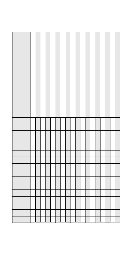
1. Overview of the Minolta dedicated functions of mecablitz and camera in
conjunction with the SCA 3302 adapter
Table 1
Flash readiness indication in camera viewfinder / monitor
Correct exposure confirmation in camera viewfinder / monitor
Automatic flash synch speed control
TTL flash control
TTL fill-in flash control
High-speed synchronisation TTL-HSS / M-HSS
Manual TTL flash exposure correction
Minolta Remote Slave Mode for digital cameras
Minolta Remote Slave Mode for analog cameras
Cordless Metz Remote (Controller) Mode
1st or 2nd curtain synchronisation
Motor zoom control
AF measuring beam control
Maximum flash range indication
Programmed auto flash mode / Full auto flash
Multi-zone flash metering (TTL preflash metering)
ADI flash control
mecablitz type
76 MZ-5 digi
70 MZ-5
70 MZ-4
60 CT-4
mit SCA 3000C
54 MZ-..
50 MZ-5
45 CL-4 digi
with SCA 3045
45 CL-4
with SCA
44 MZ-2
40 MZ-3/3i
40 MZ-1/1i
32 MZ-3
32 Z-2
• = The dedicated function is supported by the mecablitz
x = The flash unit does not automatically switch to standby mode (no auto-Off
◊ = Only with Dimage A1, A2, 5, 7, 7i, 7Hi
☞
4
••••• •••••••••••x
••••• •••••••••◊◊x
••••• •••••••••◊◊x
••••• • • • • x
••••••••••••••••••
••••• •••••••••◊◊x
••••••••• • • •••x
••••• • • • •◊◊x
3000C
••••• •••••••••◊◊•
••••• • ••••••◊◊
••••• • •••••••◊◊
••••• • ••• •◊◊
••••• • • •◊◊
function)
The dedicated functions can only be performed if both the camera and
the mecablitz support these functions (see Table 2 and refer to the
operating instructions for the given camera)!
Wake-up function for the mecablitz
Page 5
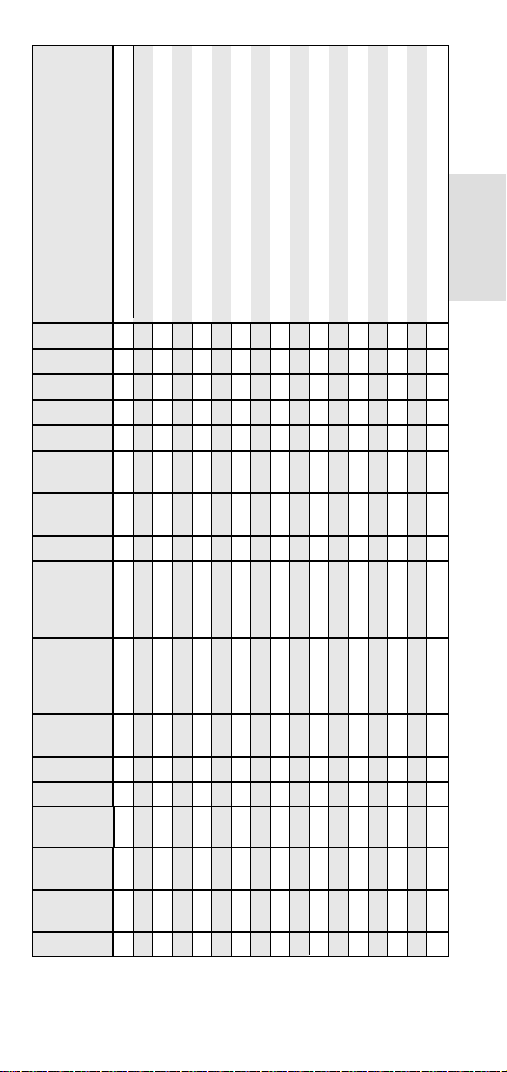
Table 2
Camera type
Dynax 9
Dynax 7
Dynax 5
Dynax 4
Dynax 800si
Dynax 600si,
700si
Dynax 505si,
505si super
Dynax 404si
Dynax 303si,
300si, 9xi, 7xi,
5xi, 3xi
Dynax 2xi,
SPix, 7000i,
8000i, 3000i,
5000i
5000, 7000,
9000
Vectis S-1
Dimage 5, 7
Dimage A1,
A2, 7i,7Hi
Dynax 7D,
5D, α100
Dimage Z1,
Z2, Z3, Z5
Dimage A200
••••••••••••••• •
•••••••••••••••••
•••••• •• •••••••
••••• •• •••••••
•••••••••••••• •
••••••••• •••• •
•••••• •• •••• •
•••••• • •••• •
••••• •• •••• •
••••• • •••• •
••••• • •• •
••••• •• •••• •
•• • ∆ •• •••••
•• • ∆ •• •••••
••• •••∆ ••••••••
•• ∆ • ••• •
•• ∆ •• ••• •
Flash readiness indication incamera viewfinder / monitor
Correct exposure confirmation in camera viewfinder / monitor
Automatic flash synch speed control
TTL flash control
TTL fill-in flash control
High-speed synchronisation TTL-HSS / M-HSS
Manual flash exposure correction
Minolta Remote Mode[WB1]
Cordless Metz Remote (Controller) Mode
1st or 2nd curtain synchronisation
Motor zoom control
ķ
AF measuring beam control
Maximum flash range indication
Programmed auto flash mode / Full auto flash
Multi-zone flash metering (TTL preflash metering)
ADI flash control
Wake-up function for the mecablitz
• = The dedicated function is supported by the camera
∆ = Only in the flash mode „A“ on the mecablitz
5
Page 6

2. Mounting the adapter
Before mounting or dismounting the standard
☞
foot 301 or SCA adapter, switch off the mecablitz by its main switch and switch off the
camera.
on the mecablitz 32 Z-2, 32 MZ-3, 40 MZ-... ,
50 MZ-5, 70 MZ-... and 76 MZ-5 digi:
• Turn the flash unit’s foot by 90° (not on the
50 MZ-5; 70 MZ-..., 76 MZ-5 digi).
• Press the retention catch against the casing,
simultaneously pushing the hitherto used standard foot or SCA adapter out of the guide.
Any cover plate that may still be in place (required
for the 301 standard foot or SCA 300 adapter)
should be gripped in the centre and withdrawn.
on the mecablitz 54 MZ-... :
• Open the battery compartment cover.
• Press the coloured unlatching button in the battery compartment, simultaneously pulling off the
standard foot or SCA adapter.
Any cover plate that may still be in place (required
for the 301 standard foot or SCA 300 adapter)
should be gripped in the centre and withdrawn.
on mecablitz 44 MZ-2:
• Press the locking lever in the middle of the
mecablitz back upwards, keep depressed (if an
SCA adapter from the SCA 3002 system is
being used then the flap on the back of the
adapter must first be opened) and simultaneously withdraw the SCA adapter or 301 standard foot towards the rear.
6
Page 7

on the camera:
• Screw the knurled nut of the adapter as far as
possible towards the head of the adapter case.
The locking pin in the adapter shoe is now fully
retracted in the case.
• Slide the adapter into the camera’s accessory
shoe.
• Screw the adapter’s knurled nut as far as possible towards the camera body to clamp the adapter in position..
When using the camera with an external flash-
☞
gun on the camera body, any camera-integrated fold-out flash must be completely folded
down.
ķ
7
Page 8

3. Switch on and shoot
You no longer have to first study many pages of
lengthy operating instructions before taking perfect
flash shots with your mecablitz in combination with
the SCA 3302 adapter and a Minolta camera. The
following short description will quickly enable you
to shoot brilliant flash pictures with the utmost
convenience.
3.1 Programmed auto flash mode
In the Program “P” mode, some cameras mix the
ambient light with the flashlight and, depending on
the camera’s programming, determine whether the
flash is to be used as the main light source or for
fill-in purposes. The camera concerned automatically adjusts a suitable shutter speed/aperture
combination and controls the flash in TTL mode
(also see Section 4.6).
3.1.1 Settings on the camera
Set your Minolta camera to Program “P” (see oper
ating instructions for the camera).
Some cameras permit various Subject Program
☞
modes to be set, such as Portrait, Landscape,
Close-up, Action, Sports. Please refer to the
operatings instructions for the given camera.
3.1.2 Settings on the flash unit
Set the “TTL” or “EM” mode on your flash unit (EM
= Easy-Mode-TTL; only on 40 MZ-..., 50 MZ-5).
For digital cameras please additionally observe
☞
the instructions in section 4.6.
8
Page 9

In most cases, use of the operating mode “P” or
the Subject Program modes of the camera in combination with your mecablitz and the SCA 3302
adapter automatically provide optimal flash exposure of the subject.
Once the above settings have been completed you
can instantly start shooting.
Advanced amateur and professional photogra-
☞
phers are advised to study the complete
instructions of this SCA 3302 adapter in order
to be able to fully exploit the diverse capabilities of the Metz mecablitz system in conjunction with the Minolta camera. But also “average users” should take the time for getting
acquainted with the versatile features and
functions offered by the adapter, mecablitz and
camera combination.
The function for activation of preflashes to
☞
reduce the “red-eye effect” (if provided by the
camera) can only be performed by the flash
unit integrated in the camera. External flash
units are not supported by this function.
ķ
9
Page 10
4. Flash photography for advanced amateur and professional photographers
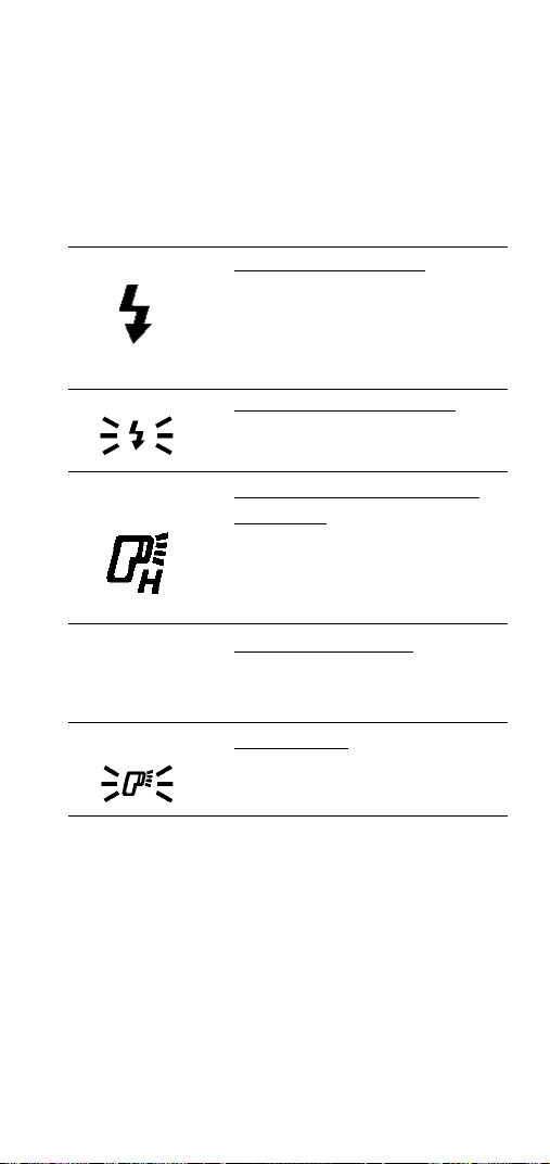
4.1 Symbols in camera viewfinder or
monitor
Symbols in viewfinder:
WL
Meaning:
Flash readiness indication:
Flash symbol lights constantly:
The mecablitz is ready for firing.
A flash is fired when the camera’s
shutter release is pressed.
Correct exposure confirmation:
Symbol flashes after shooting: The
picture was correctly exposed.
Possibility of HSS high-speed synchronisation:
Symbol lights constantly:
SS high-speed synchronisation is
possible with the mecablitz 54 MZ-....
Symbol lights constantly:
The Minolta wireless TTL remote
mode is activated.
Symbol flashes:
The existing shooting situation requires the use of flash.
The symbols indicated in your camera’s view-
☞
finder or monitor may deviate from those given
in the above table, since some symbols are
only possible on specific cameras. For more
details please refer to the operating instructions of your camera.
10
Page 11

4.2 Correct exposure confirmation on the
mecablitz
The exposure “o.k.” symbol lights up for about 2
seconds to confirm correct exposure.in the modes
TTL, EM (= Easy Mode; only on 40 MZ-..., 50 MZ-5)
and A of the mecablitz.
ķ
In the auto flash mode A, the correct exposure
☞
confirmation on the mecablitz is relevant and
not the information in the camera viewfinder.
Some flash units (mecablitz 40 MZ-2, 40 MZ-3, 40
MZ-3i, 50 MZ-5, 54 MZ-.., 70 MZ-5, 76 MZ-5 digi)
supplement the visual indication by an acoustic
signal (bleep). For further details please refer to the
operating instructions of the given mecablitz.
When using a Dimage A1, A2, 5, 7, 7i, 7Hi digi-
☞
tal camera in the TTL preflash mode or in the
ADI flash control mode, correct exposure confirmation will - for system inherent reasons only be possible with the mecablitz 40 MZ-... ,
44 MZ-2, 45 CL-4 digi, 50 MZ-5, 54 MZ-... ,70
MZ-... and 76 MZ-5 digi.
4.3 Automatic flash synch speed control
As soon as flash readiness is reached the camera
automatically switches to flash synch speed (which
depends on the type of camera). Depending on the
operating mode selected on the camera, slower
shutter speeds are retained.
11
Page 12
Shutter speeds faster than the camera’s synch
speed are possible with the mecablitz 45 CL-4 digi,
54 MZ-... in the TTL and manual HSS flash mode
(see Section 4.13).
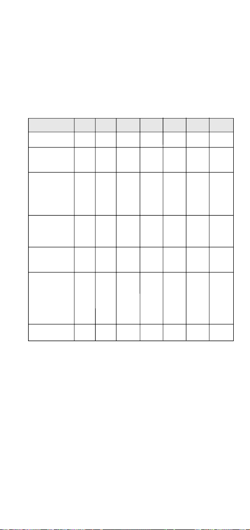
Table 3: Overview of the fastest flash synch speeds
of Minolta AF cameras
1/60 s 1/90 s 1/100 s 1/125 s 1/200 s 1/250 s 1/300 s
Dynax 9, 9xi
9000 AF,
Vectis S-1
Dynax 7, 7xi,
800si, 700si,
650si, 600si,
8000i
Dynax 505si,
505si super,
7000i
7000AF,
5000AF
Dynax 500si,
500si super,
404si, 303si,
5xi, 3xi, 2xi,
SPxi, 5000i, 4
Dynax 3000i
●
●
●
●
●
●
●
Some cameras also select slower shutter
☞
speeds to match the ambient light situation
and the focal length of the lens used. For more
details please refer to the camera manual.
12
Page 13

There is no automatic flash synch speed control
with the digital cameras Dimage .... These cameras
permit flash operation at all shutter speeds. Do not
use shutter speeds faster than 1/125 sec. if the
photographic situation requires the full light output
of the mecablitz.
4.4 Slow synchronisation
ķ
Various Minolta cameras feature a slow synch
function for flash operation. It permits the background to be properly exposed when the ambient light
level is low.This is achieved by adapting the camera’s shutter speed to the existing lighting conditions when speeds are used that are slower than
the camera’s synch speed. Slow synchronisation is
activated on the camera by pressing the “SPOT” or
“AEL” key. For more details please refer to the
operating instructions for the camera.
T
ip:
To be on the safe side, use a tripod in this operating
mode to prevent camera shake due to slow shutter
speeds.
4.5 Triggering control
The camera prevents the triggering of a flash if the
ambient light level is sufficient for an exposure in
the normal mode. The exposure is then completed
with the shutter speed given in the display or viewfinder of the camera. The triggering control is
activated when the flash-ready signal in the camera viewfinder is extinguished. In this event no flash
is fired when the camera’s shutter is tripped.
13
Page 14

On various cameras the triggering control only
works in the “P” mode and the shutter priority
mode “S” (see operating instructions for the camera). The triggering control can be deactivated on
some camera models: To do so, press and hold
down the flash button on the camera (see
operating instructions for the given camera). The
flash ready signal will again be displayed in the
camera’s viewfinder when the shutter release is
lightly touched. The camera selects a suitable
shutter speed/aperture combination and a flash is
fired when a picture is shot.
On the Dynax 800si, the triggering control fea-
☞
ture is activated by the individual function “5”
(see operating instructions for the camera).
When a Dynax 7 camera is used, triggering
control is only possible in the camera’s Full
Auto Mode (green P symbol).
Triggering control is not supported by the digi-
☞
tal cameras Dimage A1, A2, 5, 7, 7i, 7Hi .
4.6 TTL flash control
This is an automatic flash mode in which the flash
exposure is measured by a sensor inside the
camera. This sensor measures the light that reaches the film through the lens and is reflected off
the film plane. When the necessary amount of light
for a correct exposure has been obtained the
camera sends a signal to the flash unit which causes the flash to be instantly cut off. Any attachments and filters that may be used on the lens are
automatically taken into account for TTL flash control. TTL flash control is supported by all operating
14
Page 15

modes of the camera, such as Full Auto Mode, Program “P”, A, S, M and Subject Program Modes
(Portrait, Depth of Field, Landscape, Sports, Closeups, etc.).
The mecablitz 40 MZ-... and 50 MZ-5 also per-
☞
mit partial light output levels to be set (see
operating instructions of the given mecablitz).
The digital cameras Dimage A1, A2, 5, 7, 7i,
☞
7Hi support the TTL preflash mode (see Section 4.18 ) and the ADI flash control (see Section 4.19). Both are modern variants of TTL
flash operation. The normal standard TTL flash
mode is not supported by these cameras.
Full Auto Mode, Program P and Subject Program Modes:
(if available on the camera)
The camera preselects a shutter speed/aperture
combination in conformity with the existing lighting
conditions. The shutter speed selected by the
camera lies between 1/60 sec. and 1/250 sec.
depending on the camera type and the prevailing
ambient light situation (for the synch speed range
please refer to the camera’s operating instructions). Shutter speeds faster than its fastest flash
synch speed are not set by the camera. TTL flash
exposure and TTL fill-in flash are fully automatically controlled by the camera.
ķ
Camera mode “S” (shutter priority):
(if available on the camera)
In the camera mode “S” any shutter speed can be
set on the camera. If the selected shutter speed is
15
Page 16

faster than the camera’s fastest synch speed, then
the camera will automatically set the fastest possible flash synch speed when the shutter release is
touched (see Section 4.3 or refer to the operating
instructions for the camera). If the selected shutter
speed is slower than the flash synch speed, then
this shutter speed will be retained.
Depending on the specific camera type, a warning
signal can light up in the viewfinder when the
camera’s shutter speed/aperture setting range is
exceeded; please refer to the operating instructions for the given camera.
Camera mode “A” (aperture priority):
(if available on the camera)
Iin the “A” camera mode an aperture can be preselected on the camera. The camera will then
adjust a shutter speed that matches the ambient
light conditions. If the shutter speed is faster than
the camera’s fastest synch speed, then the camera
will automatically set the fastest possible flash
synch speed when the shutter release is touched.
When selecting the aperture ensure that the subject lies within the working range (distance) of the
flash unit (see aperture calculator or LC display of
the mecablitz).
Depending on the specific camera type a warning
signal may light up in the viewfinder when the
camera’s shutter speed/aperture setting range is
exceeded ; please refer to the operating instructions for the given camera.
16
Page 17

Camera mode “M” (manual exposure setting):
(if available on the camera)
An aperture and a shutter speed can be preselected on the camera when in “M” mode. If the shutter
speed is faster than the camera’s fastest synch
speed, then the camera will automatically change
over to the fastest possible synch speed when the
shutter release is touched. When selecting the
aperture ensure that the subject lies within the
indicated maximum range of the flash unit. (see
aperture calculator or LC display of the mecablitz).
ķ
4.7 TTL fill-in flash
When using TTL fill-in flash, the camera electronics
chooses the amount of flash light required for a
balanced exposure of the subject and its background. This permits shadow regions to be brightened up when taking portraits in daylight, for example. The dosage of flash light for fill-in flash control
is automatically performed by the camera.
This operating mode is not indicated by an
☞
extra symbol.
Very bright ambient light may cause the
camera to activate the triggering control.
The camera’s triggering control must then
be deactivated to enable the firing of a fillin flash. Please refer to the section “Triggering control” of this manual or to the
camera’s operating instructions.
17
Page 18

4.8 TTL flash exposure correction (manual
TTL flash exposure correction)
There are certain photographic situations where
the camera’s internal sensor can be deceived. This
is particularly the case with a dark subject in front
of a bright background (the subject will be underexposed) or a bright subject in front of a dark background (the subject will be overexposed). To overcome this problem in such a photographic situation
and still achieve a correct exposure in the TTL flash
mode, some cameras permit the flash intensity to
be influenced in the TTL and TTL fill-in flash modes
(also see operating instructions for the given
camera). On flash units with an LC display
(40 MZ-..., 44 MZ-2, 50 MZ-..., 54 MZ-...,
70 MZ-.... and 76 MZ-5 digi) the indicated maxi-
mum flash range is adapted to the selected flash
exposure correction in the TTL and A modes.
Manual TTL flash exposure correction is possible
with the following cameras: Dynax 9, 7, 800si,
700si, 600si and is set on the camera. The setting
procedure for a manual TTL flash exposure correction is described in the user’s manual of the given
camera.
With the digital cameras Dimage 5, 7, 7i, 7Hi, flash
exposure correction is set on the camera (see
user’s manual).
4.9 AF measuring beam control
The AF measuring beam is activated by the camera electronics when the ambient lighting conditions
are insufficient for automatic focusing. The AF
18
Page 19

beam projects a striped pattern on to the subject,
and the camera uses this pattern to focus automatically. The AF beam has a range of approx. 9 m
(with a 50 mm f/1.7 standard lens).
When using a Dynax 9 camera, either the came-
☞
ra-integrated AF illuminator will be activated or
the AF measuring beam of the mecablitz,
depending on the existing ambient light. The digital cameras
measuring beam of the mecablitz.
To enable activation of the AF measuring
☞
beam, the camera lens must be set to AF. Lowspeed zoom lenses can significantly curtail the
range of the AF measuring beam. The striped
pattern of the AF measuring beam only supports the central AF sensor of the camera. In
specific situations, some cameras activate
their own AF illuminator.
For cameras with several AF metering zones, we
recommend to activate only the central zone (see
operating instructions for the given camera). If a
decentral AF sensor is manually selected by the
photographer or autonomously by the camera, then
the AF measuring beam of the mecablitz may not
be activated. In this instance some cameras use
the AF illuminator integrated in the camera for the
measuring function (see operating instructions for
the camera).
Dimage ...
do not support the AF
ķ
mecablitz 45 CL-4 and 60 CT-4
These flash units of the SCA 300 system are
connected to the SCA 3302 adapter with the SCA
19
Page 20

3000C converter cable (optional extra). The AF red
light emitter integrated in the SCA 3000C takes
over the AF measuring beam function.
mecablitz 32 Z-2, 32 MZ-3, 40 MZ-... in conjunction with “Power Grip G-16”
The above flash units can be converted into a
handle-mount flashgun with the Power Grip G-16
(optional extra). The Power Grip G-16 is then
connected to the SCA 3302 adapter with the SCA
3000A connecting cable (optional extra). The AF
red light emitter integrated in the SCA 3000A takes
over the AF measuring beam function.
mecablitz 32MZ-3, 40MZ-..., 44MZ-2, 50MZ-5,
54MZ-... and 70MZ-... with the "SCA3008A"
connecting cable
If necessary, the above flash units can be used offcamera in conjunction with the SCA 3008A
connecting cable (optional extra). In this case the
AF red-light illuminator integrated in the connecting cable case takes over the function of the AF
measuring beam.
4.10 Motor zoom control (Auto Zoom)
The reflector’s flash coverage is automatically
adapted to the focal length of the camera lens. This
is only possible with flash units featuring a motorzoom reflector, such as mecablitz 32 MZ-3,
40 MZ-..., 44 MZ-2, 50 MZ-5, 54 MZ-..., 70 MZ-....,
76 MZ-5 digi.
mecablitz 40 MZ-..., 44 MZ-2, 50 MZ-5, 54 MZ-...,
70 MZ-..., 76 MZ-5 digi
After the flash unit has been switched on, the Auto
20
Page 21

Zoom Mode is automatically set if the camera is on
and activated by lightly touching the shutter release.
mecablitz 32 MZ-3
The setting slide for the zoom reflector on the
mecablitz must be adjusted to position “CZ”.
In cases where the motor zoom reflector of the
☞
mecablitz is automatically controlled by the
digital cameras Dimage ..., the focal length
position of the reflector can deviate from the
focal length set on the lens. This is because
the camera adjusts the reflector so that the
flash coverage is larger than necessary in
order to guarantee a complete illumination of
the picture. Manual setting of the reflector’s
focal length is not necessary.
ķ
4.11 Maximum flash range indication:
Only possible with the mecablitz 40 MZ-...,
44 MZ-2, 50 MZ-5, 54 MZ-... , 70 MZ-... and
76 MZ-5 digi
The Minolta cameras transmit to the flash unit the
data related to the speed of the loaded film (ISO),
the aperture, the focal length of the lens and the
adjusted exposure correction. The flash unit computes the corresponding maximum flash range on
the basis of the transmitted camera data and its
own guide number. The selected aperture and the
corresponding maximum flash range are indicated
on the flash unit’s LC display. For more details
please refer to the operating instructions for the
given mecablitz.
The maximum flash range is not indicated on
☞
the LC display when the flashgun’s reflector is
21
Page 22

tilted or when the flashgun is in cordless Metz
REMOTE mode.
Depending on the type of camera and the
☞
operating mode used, the ISO speed transmitted to the mecablitz by the camera can deviate
from the speed of the loaded film. Flash exposure will nevertheless be correct. Please do
not make any manual modifications. They may
impair a later automatic adaptation.
4.12 2nd curtain synchronisation (REAR)
Synchronisation with the shutter’s second curtain
(REAR) is particularly advantageous when shooting
moving objects that have their own source of light
with a slow shutter speed (slower than 1/30
second). Second-curtain synchronisation gives a
more realistic impression of movement because
the light streaks behind the light source instead of
building up in front of it.
If second-curtain synchronisation is selected the
mecablitz flash is not triggered the moment the
first shutter curtain opens, but a fraction of a
second before the second shutter curtain is starting. If a slow shutter speed has been chosen, or in
the “bulb” mode with the corresponding aperture,
the existing ambient light level permits traces of
moving lights to be seen on the film (e.g. light trails
left by the lights of a car). As the flash is fired right
before the end of the exposure time, the moving
subject is frozen at the end of the light trail. The
effect thus achieved seems more natural to the
perception of the eye than pictures where the flash
was fired at the beginning of the exposure,
22
Page 23
arresting the subject at the beginning of its movement and light trail.
1st curtain synchronisation
2nd curtain synchronisation
ķ
The following Minolta cameras support this function: Dynax 5, 5D, 7, 7D, 9, 800si and the digital
cameras Dimage ....
Second-curtain synchronisation (REAR mode) must
be activated on the camera (see operating instructions for the given camera).
T
ip:
Mount the camera on a tripod for this mode to
avoid camera shake with slow shutter speeds.
Do not forget to turn off this function after
☞
23
Page 24

exposure, otherwise an unwanted slow shutter
speed could result in camera shake with “normal” flash shots.
4.13 High-speed synchronisation HSS
Some Minolta cameras support HSS high-speed
synchronisation.This flash mode makes it possible
to take flash shots at shutter speeds faster than the
camera’s flash synch speed. This mode is particularly interesting in portraiture with very bright
ambient light when the depth of field is to be limited by way of a wide open lens (e.g. f/2.0)!
The mecablitz 45 CL-4 digi, 54 MZ-..., in conjunction with the SCA 3302 adapter, supports this flash
mode which is indicated on the LC display of the
54 MZ-... by the letters “HSS” (= high-speed synchronisation). The HSS flash mode can be additionally activated in the TTL mode and in the manual
mode M of the mecablitz.
Due to the system, using high-speed synchronisation diminishes the guide number, which in turn
can significantly reduce the working range of the
flashgun.
The guide number depends on the camera shutter
speed.
When using high-speed synchronisation HSS, it is
not possible to operate the flash with a secondary
reflector!
4.13.1 Switching on the HSS flash mode
Press the “Mode” button on the mecablitz 54 MZ-..
repeatedly until “TTL” or “M” flashes on the LC dis-
24
Page 25

play. Turn the setting disk until “HSS” is indicated
on the display. Then push the setting disk in the
direction of the arrow for storage. Storage will be
automatic after 5 seconds if the setting disk is not
pushed. “TTL” or “M” and in addition “HSS” are
now indicated on the LC display of the mecablitz. In
the manual mode of the mecablitz the light output
can be adapted to the individual shooting situation
by setting a partial light output level of P1/1 to
P1/256.
The HSS flash mode can only be activated if
☞
the mecablitz is mounted on an HSS-compatible camera. The camera must be switched on
and at least one exchange of data should have
been completed between mecablitz and
camera. For this purpose just lightly touch the
camera’s shutter release without tripping the
shutter (please also refer to the operating
instructions for the given mecablitz).
When high-speed synchronisation is activated
☞
on the mecablitz (HSS is displayed) it will be
completed only if the camera works with a
manually or automatically selected shutter
speed that is faster than the camera’s synch
speed.
ķ
Due to physical reasons, the HSS flash mode
☞
significantly reduces the guide number and
the maximum flash range of the mecablitz! You
should therefore pay attention to the maximum
flash range indicated on the LC display of the
mecablitz or refer to the operating instructions
and technical specifications of the flashgun.
25
Page 26

Tip:
HSS flash control should only be used when really
required.
To ensure proper operation of the internal light
☞
control of the mecablitz in the HSS flash mode,
no filter attachments (e.g. neutral density or
colour effects filters), diffusers (bouncers) etc.
must be mounted in front of the reflector. The
wide-angle diffuser (20 mm) integrated in the
mecablitz must not be swivelled in front of the
reflector. The use of attachments in the HSS
flash mode may result in exposure errors. If
you wish to use such attachments make sure
to deactivate the HSS mode.
For system-induced reasons, it is not possible
to use an external flash meter in the HSS
mode.
Remember to delete this operating mode after
shooting. Otherwise guide number and maximum flash range will unnecessarily be sacrificed.
4.13.2 Switching off the HSS flash mode
Press the “Mode” button on the mecablitz 54 MZ-..
repeatedly until “TTL” or “M” flashes on the LC display. Turn the setting disk until “HSS” is extinguished on the display. Then push the setting disk in
the direction of the arrow for storage. Storage will
be automatic after 5 seconds if the setting disk is
not pushed. The LC display of the mecablitz now
only indicates “TTL” or “M”.
26
Page 27

4.14 Auto flash mode A
A sensor inside the mecablitz controls the light output in auto flash mode A. When the amount of light
required for correct exposure has been reached,
the electronic system of the mecablitz automatically cuts off the flash. Correct exposure confirmation “o.k” is then given on the mecablitz. For auto
flash mode, the mecablitz must be set to “A”.
The mecablitz 40 MZ-... , 44 MZ-2, 50 MZ-5,
☞
54 MZ-... and 70 MZ-... models also permit
partial light output levels to be set (please refer
to the operating instructions for the individual
mecablitz).
Various cameras only permit TTL flash mode.
☞
See operating instructions for the individual
camera.
mecablitz 60 CT-4, 45 CL-4, 32 MZ-3, 32 Z-2:
Select a suitable auto aperture on the mecablitz.
Make sure that the shooting distance lies within
the working range of the auto aperture.
ķ
In the camera modes A (aperture priority mode) or
M (manual mode) the aperture selected on the
mecablitz must be manually set on the camera.
mecablitz 40 MZ-...,
50 MZ-5, 54 MZ-..., 70 MZ-... and 76 MZ-5 digi:
The flash unit automatically adjusts its auto aperture to the aperture selected on the camera. Make
sure that the subject lies within the maximum flash
range of the mecablitz (see LC display).
44 MZ-2, 45 CL-4 digi,
27
Page 28

4.14.1 Manual flash exposure correction
in the auto flash mode A
The mecablitz 44 MZ-2, 54 MZ-... , 70 MZ-... and
76 MZ-5 digi permit a flash exposure correction
value to be set in the auto flash mode A (refer to the
operating instructions of the mecablitz for the setting procedure).
4.14.2 Auto flash mode A with digital
cameras
If a digital camera Dimage ... is used with a mecablitz that works in the auto flash mode A, a measuring preflash will not be fired before shooting the
picture. Consequently, the camera will not conduct
an automatic white balance with the result that the
shots may be colour cast.
4.15 Manual flash mode M
In the manual flash mode M the light is not controlled by a sensor. Instead the mecablitz operates
at full light output. Partial light output levels can be
used with some mecablitz models (see operating
instructions for the given mecablitz). For manual
flash mode, the mecablitz is set to “M” (the mecablitz 32 Z-2 and 32 MZ-3 have an additional “W”
setting for a partial light output).
The camera is set to mode A (aperture priority
mode) or M (manual camera mode).
Various cameras only permit the TTL flash
☞
mode. See operating instructions for the individual camera.
28
Page 29

mecablitz 60 CT-4, 45 CL-4, 45 CL-4 digi,
32 MZ-3, 32 Z-2
Select “M” or a partial light output on the mecablitz. Find the required working aperture using the
aperture calculator on the mecablitz. Then set on
the camera this working aperture or the aperture
that comes closest to it.
In the camera mode M it is additionally necessary
to set a shutter speed that equals or is slower than
the camera’s fastest synch speed. Use a tripod for
slow shutter speeds to prevent camera shake.
ķ
mecablitz 40 MZ-...,
70 MZ-..., 76 MZ-5 digi:
The camera automatically transmits the adjusted
aperture to the mecablitz. Set the appropriate aperture/partial light output combination (camera /
mecablitz) to determine the required flash-to-subject
distance. The distance for a correct exposure is indicated on the LC display of the mecablitz and is
adapted to the aperture and partial light output setting.
In the camera mode M it is additionally necessary
to set a shutter speed that equals or is slower than
the camera’s fastest flash synch speed. Use a tripod for slow shutter speeds to prevent camera
shake.
44 MZ-2,
50 MZ-5, 54 MZ-...,
4.15.1 Manual flash mode M with digital
cameras
If a digital camera
blitz that works in the manual flash mode M, a measuring preflash will not be fired before shooting the
picture. Consequently, the camera will not conduct
Dimage ...
is used with a meca-
29
Page 30

an automatic white balance with the result that the
shots may be colour cast.
4.16 Wireless Minolta TTL Remote Mode
Various Minolta cameras (xi-, si-series, Dynax 9
and Dynax 7, Dimage 7i, 7Hi) offer the possibility of
cordless flash operation in the Wireless Minolta
TTL Remote Mode. A controller mounted on the
camera permits wireless remote TTL control of one
or more slave flash units. The function of the controller is taken over by a Minolta flash unit 5400xi /
5400HS / 3600HS(D) / 5600HS(D), the Minolta
Wireless Remote Flash Controller or the folded-out
flash unit integrated in the camera. Four remote
addresses (channels) can be selected to ensure
that different Minolta TTL remote systems do not
interfere with each other in the same room.
A certain remote camera address can only be
☞
set on a Minolta flash unit (see above), the
Minolta Wireless Remote Flash Controller or a
mecablitz 54 MZ-..., 70 MZ-... or 76 MZ-5 digi
with the SCA 3302 adapter. The remote
address cannot be set on the camera, nor does
the camera display the remote address.
The following mecablitz models can be used as slaves together with the SCA 3302 adapter: mecablitz
40 MZ-..., 45 CL-4 digi, 50 MZ-5, 54 MZ-..., 70 MZ... and 76 MZ-5 digi.
Please note:
• The mecablitz must be in the "TTL" mode. If a
Dimage 7i or 7Hi is used in conjunction with the
54MZ-..., 70MZ-... and 76 MZ-5 digi mecablitz,
30
Page 31

the flash unit first automatically switches to the
Manual M and "GnC" mode (see 4.18.2).
• The camera must be set to "Wireless Mode" or
"WL" (see camera’s operating instructions). With
Dimage 7i and 7Hi in combination with the
mecablitz 54MZ-..., 70MZ-... and 76 MZ-5 digi ,
the flash unit then automatically switches to TTL
mode.
• The controller and the slave(s) must be set to the
same remote address! With the mecablitz 44
MZ-2 only "Ad1" is possible.
• The mecablitz can only be used as a slave and
not as a controller.
• Since the mecablitz (slave) is controlled by weak
flashes from the controller, the ambient light level
should be as low as possible, and the flash-tosubject distance should not be wider than 5 m.
• The sensor of the SCA 3302 adapter must be
aligned in such a manner that it can receive the
signals from the controller.
ķ
• The remote mode does not allow the use of shutter speeds faster than 1/60th sec. (on some
cameras only 1/45th sec.).
• The secondary reflector (where applicable) of the
mecablitz must not be switched on.
• The AF measuring beam of the mecablitz will
start flashing when flash readiness has been
achieved.
• The camera’s Eye-Start system must not be
activated so that a test flash can be fired with the
camera’s SPOT or AEL button.
31
Page 32

The motor-zoom reflector of the mecablitz is
☞
automatically set to the 24mm position when
in slave mode to provide the widest possible
coverage of flash light. However, the reflector
position of the mecablitz can be manually
adjusted to match the existing photographic
requirements (see operating instructions of the
given mecablitz). The reflector position of the
mecablitz need not coincide with the focal
length of the lens. The flash unit’s reflector
must be directed towards the subject.
Please note that an activated automatic
☞
switch-off of the mecablitz (Auto-Off) is also
effective in slave mode so that the flash unit
automatically switches off after 1 minute, 3
minutes or 10 minutes! On the mecablitz
44MZ-2 this will be accompanied by deactivation of the slave mode. The mecablitz 54 MZ... can be switched on again by turning the setting disk. A mecablitz from the 40MZ-... series
must be switched off and then on again with
the main switch. For activation and deactivation of the Auto-Off function please refer to the
operating instructions for the given mecablitz.
For "normal" flash mode (mecablitz mounted
☞
on the camera) deactivate the "Wireless"
mode (WL) on the camera!
The following wireless modes are possible:
1.
Controller: Folded-out camera flash unit
1.1 The controller does not contribute to the illumination but only controls the slave (mecablitz)
which illuminates the subject on its own.
1.2 The controller contributes one-third of the illu-
32
Page 33

mination of the subject, while the slave (mecablitz) takes over the remaining two-thirds
(automatically controlled light output “Ratio”).
2.
Controller: A Minolta flash unit 5400xi /
5400HS / 3600HS(D) / 5600HS(D):
Not possible with Dimage 7i, 7Hi!
☞
2.1 The controller does not contribute to the exposure but only controls the slave (mecablitz)
which illuminates the subject on its own.
2.2 The controller contributes one-third of the illumination of the subject while the slave (mecablitz) takes over the remaining two-thirds
(automatically controlled light output “Ratio”).
3.
Controller: The Minolta Wireless Remote Flash
Controller
Not possible with Dimage 7i, 7Hi!
☞
3.1 The controller only controls the slave. The slave
(mecablitz) illuminates the subject on its own.
3.2 The controller controls two slaves (mecablitz).
One slave contributes one-third of the illumination, the second slave the remaining two-thirds
(automatically controlled light output “Ratio”).
ķ
Please refer to the corresponding Minolta operating instructions (camera, flash unit or remote
flash controller) for the controller setting procedure.
Setting the slave mode on the mecablitz
44 MZ-2, 54 MZ-..., 70 MZ-... and 76 MZ-5 digi:
Initialisa
Attach the SCA 3302 adapter to the mecablitz (or
tion:
33
Page 34

the controller of the 70 MZ-... and 76 MZ-5 digi),
mount on the camera and switch on. Switch the
camera to wireless controller mode (see the operating instructions for the given camera). Lightly
touch the shutter release without tripping the shutter. The mecablitz is switched over to slave mode.
“SL” is indicated on the display as well as the
remote address: “Ad1” to “Ad4” are possible. Only
"Ad1" is possible with 44 MZ-2.
The additional “rA1” and “rA2” (only with
☞
54 MZ-..., 70 MZ-... and 76 MZ-5 digi) display
is only of significance when in “Ratio” mode
with two slave flash units (mecablitz)!
To change the remote address (only with 54 MZ-...,
70 MZ-... and 76 MZ-5 digi) depress the “Mode”
button on the mecablitz until “TTL” flashes on the
display. Turn the setting disk and adjust the required remote address. Press the setting disk in
the direction of the arrow to store the setting. Storage is automatic after 5 sec. if the setting disk is
not pressed. Finally, lightly touch the shutter release without tripping the shutter. The camera will
now automatically take over the remote address of
the mecablitz.
Remove the mecablitz with the SCA 3302 adapter
from the camera and mount on the stand (optional). Set up the mecablitz with stand in the required position or mount on a tripod.
The slave settings for the remote address (Ad1
☞
to Ad4) and the automatically controlled light
output ratio (rA1 or rA2) are retained after the
mecablitz (only with 54 MZ-..., 70 MZ-... and
76 MZ-5 digi) has been switched off.
34
Page 35

Testing the remote mode:
Switch on the camera and the controller or fold out
the camera’s built-in flash. Await the flash readiness signal of the controller, the camera-integrated
flash, or slave flash unit. Fire a remote test flash
with the SPOT or AEL button on the camera.
W
arning: On some cameras the flash button must
be simultaneously kept depressed (refer to the
operating instructions for the given camera). If the
flash set-up is working properly, then the slave
flash unit will respond by firing a brief flash. The
flash set-up is then ready for picture shooting.
If the slave flash unit does not respond, then
☞
re-align the sensor of the SCA 3302 adapter so
that it recognises the controlling pulses of the
controller, or repeat the initialisation procedure
(see above). Finally, fire another test flash.
Setting the slave flash mode on the mecablitz
40 MZ-... and 50 MZ-5:
Attach the SCA 3302 adapter to the mecablitz,
mount on the stand (optional) and switch on. Press
the “Remote” button on the mecablitz until “SL”
(slave mode) appears on the mecablitz display.
Flash readiness is indicated by the flashing AF
measuring beam of the mecablitz.
ķ
The additional rA1 or rA2 display is only of signifi-
☞
cance in “Ratio” mode with two slave flash units
Controller: Camera’s built-in flash
The controller and slave set-up operates with the
remote address supplied by the camera. This
remote address cannot be changed.
35
Page 36

Controller: Minolta flash units 5400xi / 5400HS /
3600HS(D) / 5600HS(D) or Minolta Wireless Flash
Controller
One of four remote addresses can be manually
preselected. Please refer to the corresponding
Minolta operating instructions to set the controller
mode for the Minolta flash unit and to select the
remote address.
Initialising and testing the remote mode:
Switch on the camera and controller or fold out the
camera’s built-in flash. Await the flash readiness
signal of the controller or camera’s flash unit. Fire a
remote test flash with the SPOT or AEL button on
the camera.
W
arning:
On some cameras the flash button must be simultaneously kept depressed (refer to the operating
instructions for the given camera). The slave flash
unit (mecablitz with SCA 3302 adapter) learns the
number of the remote channel through this remote
test flash. If the flash set-up is working properly,
then the slave flash unit will respond by firing a
brief flash. “SL”, together with the number of the
remote channel, e.g.“SL1”, is indicated on the display of the flash unit.
The slave flash unit must be ready for firing
☞
during the initialising procedure.
If the slave flash unit does not respond, then switch
it off briefly, re-align the sensor of the SCA 3302
adapter so that it recognises the controlling pulses
of the controller. Finally, repeat the initialising procedure.
36
Page 37

The initialising procedure has to be repeated
☞
after the mecablitz has been switched off
(including Auto-Off in connection with mecablitz 40 MZ-...) and on again.
The remote set-up (controller and slave) is ready
for shooting pictures after initialisation has been
successfully completed!
Automatically controlled light output “Ratio”:
The automatically controlled light output “Ratio”
divides the share of light in a ratio of 1/3 and 2/3
between the flash units.
System-inherent reasons do not permit the
☞
Ratio Mode with Dimage ....
“Ratio” mode with the camera’s built-in flash
and a slave flash unit:
The setting procedure for the camera, controller
and slave is the same as for the normal remote
mode. One-third of the light output is assigned to
the camera’s built-in flash (controller). For this purpose keep the flash button on the camera depressed during shooting (see the operating instructions for the given camera). The remaining
two-thirds are assigned to the slave flash unit
(mecablitz). The mecablitz must be in slave mode
and ready for firing.
ķ
The display of “rA1” and “rA2” on the meca-
☞
blitz is only of significance when two slave
flash units are used.
The camera’s built-in flash unit can be re-
☞
placed by a Minolta flash unit 5400xi / 5400HS
/ 3600HS(D) / 5600HS(D). For the settings on
37
Page 38

the Minolta flash unit please refer to the corresponding operating instructions.
If the flash button is not kept depressed during
☞
shooting, then the flash light of the controller
does not contribute to the exposure of the subject, i.e. “Ratio” mode is not executed.
“Ratio” mode with two slave flash units:
In “Ratio” mode with two slave units the light output of the two flashes is controlled by the controller
on the camera in a 1/3 to 2/3 ratio. The light output
share assigned to each slave is adjusted on the
individual mecablitz. 1/3 is indicated as “rA1” and
2/3 as “rA2” on the mecablitz display.
Setting procedure for the mecablitz 54 MZ-...,
70 MZ-... and 76 MZ-5 digi
Initialisa
Attach the SCA 3302 adapter to the mecablitz (or
the controller on the 70 MZ-... and 76 MZ-5 digi)
and mount on the camera. Switch on the camera
and the mecablitz. Adjust the camera to controller
mode (refer to the operating instructions for the
given camera). Set the required remote address
and light output share on the mecablitz. The mecablitz display will indicate SL for slave mode. Press
the “Mode” button on the mecablitz until TTL flashes on the display.Then turn the setting disk on the
mecablitz and adjust the required remote address
and light output ratio.
Example:
The remote address 2 “Ad2” and a 2/3 light output
ratio “rA2” are to be adjusted.
38
tion:
Page 39

Initially, the display of the mecablitz will indicate
“SL”, “Ad1” and “rA1”. This means that the mecablitz has been set to slave mode (SL) with the
remote address 1 (Ad1). In Ratio mode a 1/3 light
output is assigned to the mecablitz (rA1). To adjust
the required settings press the “Mode” button on
the mecablitz until ’”TTL” flashes on the display.
Turn the setting disk anti-clockwise until “Ad2”
(remote address 2) and “rA2” (2/3 light output) are
displayed. Press the setting disk in the direction of
the arrow to store the setting. Storage is automatic
after 5 s if the setting disk is not pressed.
Lightly touch the camera’s shutter release so that
the camera can take over the remote channel setting from the mecablitz. Remove the mecablitz with
the SCA 3302 adapter from the camera and mount
on the stand (optional). Place the mecablitz with
stand in the required position or mount on a tripod.
Both slave flash units must be set to the same
☞
remote address “Ad...”! The display of one
slave must indicate “rA1”, and the other “rA2”.
Setting procedure with the mecablitz 45CL-4
digital
ķ
This flashgun only supports remote address 1.
• Equip flashgun with adapter.
• Attach flashgun with adapter to the camera.
• Switch on the flashgun and set to "TTL".
• Switch on the camera and set to "WIRELESS".
•
Activate the camera by touching the release button.
• "TTL" disappears from the flashgun's display
window and the " " appears indicating that
39
Page 40

the flashgun is in flash mode "Remote-SLAVE".
• Detach the flashgun from the camera - once
removed, the flashgun can now be used as a slave flashgun.
• Open out the camera flash
• Trigger a test flash on the camera, the slave flashgun should respond with a delayed flash
• The setup is now ready for use
Important: When the slave flashgun is switched
off it loses the remote function and
has to be switched back into remote
mode by connecting it with the camera.
It is possible to deactivate the remote function:
a) by switching off the flashgun
b) by connecting it with the camera - deselecting
"WIRELESS" on the camera and activating the
camera by touching the camera's release button
Setting procedure with the mecablitz 76MZ-5
digital
• Equip flashgun with adapter
• Attach flashgun with adapter to the camera
• Switch on flashgun and set to "TTL"
• Switch on camera and set to "WIRELESS"
• To set the remote address (if not already programmed beforehand):
• Press the "Sel" key twice on the mecablitz and
use the keys to select "REMOTE".
40
Page 41

• Press the "Set" key on the mecablitz and use the
keys to select a remote address Sl1....Sl4
• Press the "Set" key on the mecablitz
• Touch the camera's release button in order for
the remote address you have set to be adopted
by the camera.
ķ
• The display of the mecablitz shows "SL" under
the TTL display
• Disconnect flashgun and camera
• Open out the camera flash
• Trigger a test flash on the camera, the slave
flashgun should respond with a delayed flash
• The setup is now ready to use
Important: When the slave flashgun is switched
off it loses the remote function and has
to be switched back into remote mode
by connecting it with the camera.
It is possible to deactivate the remote function:
a) by switching off the remote function on the
flashgun
b) by deselecting "WIRELESS" on the camera
Testing the “Ratio” mode:
Switch on the camera and the controller or fold out
the camera’s built-in flash. Await the flash readiness signal of the controller or the camera’s flash
unit. Fire a remote test flash with the SPOT or AEL
button on the camera.
On some cameras the flash button must be
☞
simultaneously kept depressed (refer to the
41
Page 42

camera’s operating instructions for details). If
the set-up operates correctly the slaves will
respond successively with a brief flash. The
set-up is then ready for shooting.
If a slave flash unit does not respond, then re-
☞
align the sensor of the SCA 3302 adapter so
that it recognises the controlling pulses from
the controller and repeat initialisation (see
above). Finally, repeat the test flash procedure.
To terminate the “Ratio” mode with two slave flash
units and continue with only one slave, it is sufficient to simply switch off any one of the two units.
The indication of “rA1” and “rA2” on the dis-
☞
play of the mecablitz is only of significance if
two slave flash units are being operated.
Setting procedure for the mecablitz 40 MZ-...
and 50 MZ-5:
Attach the SCA 3302 adapter to the mecablitz (or
controller of 50 MZ-5) and switch on.
Press the “Remote” button on the mecablitz until SL
is indicated on the display. Select the required light
output ratio with the “+” or “-” button. SL (slave)
and the selected light output ratio (rA1 for 1/3 and
rA2 for 2/3) will be displayed.
Mount the mecablitz with SCA 3302 adapter on the
stand (optional). Place the mecablitz with stand in
the required position or mount on a tripod.
The ratio setting of the mecablitz is retained
☞
after the flash unit has been switched off.
42
Page 43

Initialising procedure and testing the “Ratio”
mode:
One slave must have been adjusted to “rA1” and
the other to “rA2” before the initialising procedure.
Both slave flash units must be ready for firing.
Switch on the camera and controller or fold out the
camera’s built-in flash. Await the flash readiness
signal of the controller or the camera’s flash unit.
Fire a remote test flash with the SPOT or AEL button on the camera.
W
arning:
On some cameras the flash button must be simultaneously kept depressed (refer to the camera’s
operating instructions for details). The slaves
(mecablitz with SCA 3302 adapter) learn the number of the remote channel as a result of this remote
test flash. If the set-up operates correctly the
slaves will respond successively with a brief flash.
The display of the slave units will indicate the number of the remote channel alongside the “SL”.
If a slave does not respond, then switch it off
☞
briefly, re-align the sensor of the SCA 3302
adapter so that it recognises the controlling
pulses of the controller. Finally, repeat the
initialising procedure.
ķ
The initialising procedure must be repeated
☞
after the mecablitz has been switched off
(including Auto-Off of the mecablitz 40 MZ-...)
and on again.
The set-up (controller and slaves) is ready for
shooting after initialisation has been successfully
completed.
43
Page 44

Deactivating the Minolta TTL remote mode:
Mount the mecablitz with SCA 3302 adapter on the
camera. Switch on the camera and the mecablitz.
Cancel the “Wireless” or “WL” remote function on
the camera (see operating instructions for the
given camera). Lightly touch the shutter release
without tripping the shutter. This deactivates the
slave mode on the mecablitz which will then operate in normal mode.
With the mecablitz 44MZ-2 the slave mode is cancelled when the mecablitz switches to standby
mode (Auto-Off) or when it is switched off by way
of the main switch.
4.17 Cordless Metz Remote Mode
The mecablitz flash units 40 MZ-..., 44 MZ-2,
☞
50 MZ-5, 54 MZ-.., 70 MZ-.. and 76 MZ-5 digi
permit wireless TTL flash operation (Metz TTL
Remote) and wireless automatic flash control
(Metz Automatic Remote) with several flash
units (44 MZ-2 only as a slave). The camera is
not switched to "Wireless" mode (WL) for the
cordless Metz remote mode!
Light output control of the off-camera mecablitz
flash units (slaves) is handled by the mecablitz
mounted on or at the camera which functions as
the controller. Off-camera slave flash units additionally require the slave adapter "SCA 3082" or
"SCA 3083 digital" for the Metz remote mode.
Please refer to the corresponding section in the
operating instructions of your mecablitz for the setting procedure of the Metz Remote Mode.
44
Page 45

The camera’s shutter speed must not be faster
☞
than 1/60th sec for the Cordless Metz Remote
Mode! The Dimage ... digital cameras only
support the Metz Automatic Remote Mode.
4.18 Multi-zone flash exposure metering
(preflash metering or TTL preflash)
When the camera’s shutter release is pressed for
picture shooting a pre-flash is fired to measure the
subject’s reflection. With the aid of its exposure
system and its 14-segment honeycomb pattern
multi-zone metering (Dynax 7 / Dynax 9), the
camera’s electronics captures the light reflected by
the subject. It then determines the optimal
weighting for the 4 segments of flash exposure
metering on the basis of the measured light distribution and the information given by the AF system.
The subsequent main flash and the consequent
exposure are performed according to the results of
this pre-flash metering. For the setting procedure
of multi-zone flash metering on the camera and
other details please refer to the camera manual.
ķ
Because of the preflash, it is not possible for
☞
system-induced reasons to use an external
flash meter for multi-zone flash metering.
4.18.1 Dynax 7, 9
For system-induced reasons only the meca-
☞
blitz 54 MZ-... can be used for multi-zone flash
exposure metering with the above cameras!
The mecablitz 54 MZ-... must be set to TTL-HSS
mode for multi-zone flash exposure metering (see
Section 4.13.1). Multi-zone flash exposure meter-
45
Page 46

ing is not specifically displayed by the mecablitz.
The mecablitz will not fire a pre-flash when:
☞
The reflector is swivelled out of its normal
position.
Second-curtain synchronisation has been set
(REAR mode).
The secondary reflector of the mecablitz has
been switched on.
The camera operates with mirror lock-up.
In this instance the mecablitz will operate with
normal TTL flash control.
To ensure proper operation of multi-zone flash
☞
exposure metering with the above cameras no
filter attachments (e.g. neutral density or
colour effects filters), diffusers (bouncers) etc.
must be mounted in front of the reflector. The
wide-angle diffuser (20mm) integrated in the
mecablitz must not be swivelled in front of the
reflector. Multi-zone flash exposure metering
must be deactivated if any of the aforementioned attachments are to be used. For this
purpose it will be sufficient to switch the
mecablitz from TTL-HSS mode to TTL mode
(see Section 4.13.2 or refer to the camera’s
operating instructions).
4.18.2 Dimage A1, A2, 5, 7, 7i, 7Hi
For system-induced reasons TTL pre-flash
☞
metering with the above digital cameras is
possible with the following flash units: mecablitz 32 Z-2, 32 MZ-3, 40 MZ-1, 1i, 3, 3i,
46
Page 47

44 MZ-2, 45 CL-4 (with SCA 3000 C adapter),
50 MZ-5, 54 MZ-..., 70 MZ-.. and 76 MZ-5 digi
For multi-zone flash expsoure metering the TTL
mode must be selected on the mecablitz. There are
no restrictions with regard to reflector attachments. Please refer to the hints given in the camera’s operating instructions.
mecablitz 32 Z-2, 32 MZ-3, 40 MZ-..., 45 CL-4,
50 MZ-3:
This flash mode is not specifically indicated on the
mecablitz or the SCA adapter.
ķ
4.18.3 Dynax 5D, 7D,αα100
(54 MZ-.., 45 CL-4 digi, 76 MZ-5 digi only)
When a Dynax 7D is operated in ADI mode, the flash
unit must always be switched to TTL-HSS mode if
this setting is available on the given flash unit. The
system does not allow TTL flash mode when using a
flash unit without the TTL-HSS function.
With the mecablitz 76MZ-5 digital, ADI flash control
is only possible in TTL flash mode for cameras
Dynax 7D, Dynax 5D and
With the mecablitz 45 CL-4 digital, ADI flash control
is possible in flash modes TTL and TTL-HSS for
cameras Dynax 7D, Dynax 5D and
Sony α100
Sony α100
.
.
4.19 ADI flash control (Advanced
Distance Integration)
ADI flash control is a multi-zone flash metering
system (pre-flash) expanded by guide number control. To enable guide number control, the camera
47
Page 48

must be fitted with an AF-D lens (Dynax 5, Dynax 7)
that transmits the necessary distance information
to the camera. Please refer to the camera manual
for details about the setting procedure of ADI flash
control on the camera).
On account of pre-flash metering ADI flash
☞
control does not allow the use of an external
flash meter.
4.19.1 Dynax 4, 5, 7
For system-induced reasons only the mecablitz
54 MZ-... can be used for ADI flash control with the
above cameras.
The mecablitz must be set to TTL-HSS mode for
ADI flash control (see Section 4.13.1) ADI flash
control is not specifically displayed on the mecablitz.
The mecablitz will not fire a pre-flash when:
☞
The reflector is swivelled out of its normal
position.
Second-curtain synchronisation has been set
(REAR mode).
The secondary reflector of the mecablitz has
been switched on.
The camera operates with mirror lock-up.
In this instance the mecablitz will operate with
normal TTL flash control.
To ensure proper operation of ADI flash control
☞
with the above cameras no filter attachments
(e.g. neutral density or colour effects filters),
diffusers (bouncers) etc.,must be mounted in
front of the reflector. The wide-angle diffuser
48
Page 49

(20mm) integrated in the mecablitz must not
be swivelled in front of the reflector. ADI flash
control or the preflash function must be deactivated if any of the aforementioned attachments are to be used. For this purpose it will
be sufficient to switch the mecablitz from TTLHSS mode to TTL mode (see Section 4.13.2 or
refer to the camera’s operating instructions).
ķ
4.19.2 Dimage A1, A2, 5, 7, 7i, 7Hi
For system-induced reasons ADI flash control with
the above digital cameras can be performed in
conjunction with the following flash units: mecablitz 32 Z-2, 32 MZ-3, 40 MZ-1, 1i, 3, 3i, 45 CL-4
(with SCA 3000C), 50 MZ-5, 54 MZ-..., 70 MZ-..
and 76 MZ-5 digi.
For ADI flash control the mecablitz must be set to
TTL mode.
If an attachment is mounted in front of the
☞
reflector or when bouncing the flash, it is
advisable to use TTL pre-flash metering
instead of the ADI flash control (see 4.18). For
further information please refer to the camera’s operating instructions.
mecablitz 32 Z-2, 32 MZ-3, 40 MZ-..., 44 MZ-2,
45 CL-4, 50 MZ-3:
This flash mode is not specifically indicated on the
mecablitz or the SCA adapter.
4.20 Wake-up function for the mecablitz
The mecablitz 44MZ-2 and 54MZ-... are fitted with
a facility to automatically switch off the flash unit
1, 3 or 10 minutes after the last flash was fired or
49
Page 50

after the last setting was made (Auto-Off function).
When automatically switched off, the mecablitz is
in a standby state.
As soon as the camera’s shutter release is touched,
the SCA 3302 adapter will “wake up” the mecablitz
and switch it on again (wake-up function).
5. Troubleshooting hints
Should, for example, the LC display of your mecablitz indicate meaningless information or should
the flash unit not function properly you can try to
overcome this problem as follows:
1a) Switch off the flash unit by its main switch.
1b) Remove the batteries.
1c) Switch on the flash unit for about 1 second and
then switch it off again.
1d) Re-insert the batteries.
or / and:
2a) Switch off both the camera and the mecablitz.
2b) Remove the SCA adapter from the mecablitz
and then remount it.
The mecablitz should operate properly when it is
switched on again. Contact your local dealer
should this not be the case.
For the latest news and information, please
☞
visit the Metz homepage in the Internet at
www.metz.de
50
Page 51

ķ
51
Page 52

ƴ
1. Panoramica delle funzioni dedicate
Minolta di mecablitz e camera con
adattatore SCA 3302 . . . . . . . . . . . . . . . 54
2. Montaggio dell’adattatore . . . . . . . . . . . 56
3. Guida rapida per fotografare con il flash. 58
3.1 Automatismo di programma flash . . . . . 58
3.1.1 Impostazione sulla camera: . . . . . . . . . . 58
3.1.2 Impostazione sul flash:. . . . . . . . . . . . . . 58
4. Uso del flash nel campo amatoriale
avanzato e professionale . . . . . . . . . . . . 60
4.1 Indicazioni nel mirino o nel monitor
della camera . . . . . . . . . . . . . . . . . . . . . 60
4.2 Indicazione di corretta esposizione sul
mecablitz . . . . . . . . . . . . . . . . . . . . . . . . 61
4.3 Controllo automatico del tempo di
sincronizzazione. . . . . . . . . . . . . . . . . . . 61
4.4 Sincronizzazione lenta:. . . . . . . . . . . . . . 63
4.5 Soppressione del lampo. . . . . . . . . . . . . 63
4.6 Controllo flash TTL . . . . . . . . . . . . . . . . . 64
4.7 Lampi di schiarita TTL . . . . . . . . . . . . . . 67
4.8
Compensazione dell’esposizione TTL (compensazione manuale dell’esposizione TTL)
4.9 Controllo del raggio di misurazione AF . . 69
4.10 Controllo parabola zoom motorizzata
(Auto-Zoom). . . . . . . . . . . . . . . . . . . . . . 71
4.11 Indicazione del campo d’utilizzo flash. . 72
4.12
52
Sincronizzazione sulla 2a tendina (REAR) 73
. . . . 68
Page 53

4.13 Sincronizzazione veloce HSS . . . . . . . . 75
4.13.1 Impostazione del modo flash HSS . . . . 75
4.13.2 Disattivazione del modo flash HSS . . . . 77
4.14 Modo flash automatico A . . . . . . . . . . . 77
4.14.1 Compensazione dell’esposizione flash
nel modo flash automatico . . . . . . . . . . 79
4.14.2 Modo flash automatico A con camere
digitali . . . . . . . . . . . . . . . . . . . . . . . . . 79
4.15 Modo flash manuale M. . . . . . . . . . . . . 79
4.15.1 Modo flash manuale M con camere
digitali . . . . . . . . . . . . . . . . . . . . . . . . . 80
4.16 Modo Minolta TTL-Remote senza cavo
“WIRELESS”. . . . . . . . . . . . . . . . . . . . . 81
4.17 Modo Metz-Remote senza cavo . . . . . . 96
4.18 Misurazione multizone dell’esposizione
al flash (misurazione con prelampo
o prelampo TTL). . . . . . . . . . . . . . . . . . 97
4.18.1 Dynax 7 / Dynax 9 . . . . . . . . . . . . . . . . 98
ƴ
4.18.2 Dimage A1, A2, 5, 7, 7i, 7Hi . . . . . . . . . 99
4.18.3 Dynax 5D, 7D, Sony α100 . . . . . . . . . . 99
4.19 Controllo del flash ADI (Advanced
Distance Integration) . . . . . . . . . . . . . 100
4.19.1 Dynax 4, 5, 7 . . . . . . . . . . . . . . . . . . . 100
4.19.2 Dimage A1, A2, 5, 7, 7i, 7Hi . . . . . . . . 101
4.20 Funzione Wake-Up per il mecablitz. . . 102
5. In caso di anomalie di funzionamento. 103
53
Page 54

1. Panoramica delle funzioni dedicate
Minolta di mecablitz e camera con
adattatore SCA 3302
Tabella 1
TSpia di carica del flash nel mirino della camera / Monitor
Indicazione di corretta esposizione nel mirino / Monitor
Controllo automatico del tempo di sincronizzazione
Controllo flash TTL
Controllo TTL del lampo di schiarita
Sincronizzazione veloce TTL-HSS / M-HSS
Compensazione manuale TTL dell’esposizione
Modo Minolta-Remote asservito (Slave) per camere digitali
Modo Minolta-Remote asservito (Slave) per camere analogo
Modo Metz-Remote-(Controller) senza cavo
Sincronizzazione sulla 1a o sulla 2a tendina
Controllo Zoom motorizzato
Controllo del raggio di misurazione AF
Indicazione del campo d’utilizzo del flash
Automatismo di programma flash / Flash compl. automatico
Tipo mecablitz
76 MZ-5 digi
70 MZ-5
70 MZ-4
60 CT-4
mit SCA 3000C
54 MZ-3/4
50 MZ-5
45 CL-4 digi
con SCA 3045
45 CL-4
con SCA 3000C
44 MZ-2
40 MZ-3/3i
40 MZ-1/1i
32 MZ-3
32 Z-2
• = funzione dedicata supportata dal mecablitz
x = Il flash non commuta automaticamente nello stato stand by (non
◊ = solo con Dimage A1, A2, 5, 7, 7i, 7Hi
☞
54
••••• •••••••••••x
••••• •••••••••◊◊x
••••• •••••••••◊◊x
••••• • • • • x
••••••••••••••••••
••••• •••••••••◊◊x
••••••••• • • •••x
••••• • • • •◊◊x
••••• •••••••••◊◊•
••••• • •••••••◊◊
••••• • •••••••◊◊
••••• • ••• •◊◊
••••• • • •◊◊
esiste la funzione Auto Off)
Le funzioni dedicate supportate possono essere eseguite solo se
la camera e il mecablitz supportano tali funzioni (v. anche tabella 2
o le istruzioni per l’uso della camera) !
Misurazione multizone dell’espos. al flash ( misurazione prelampo TTL)
Controllo flash ADI
Funzione Wake-Up per il mecablitz
Page 55

Tabella 2
Spia di carica del flash nel mirino della camera / /Monitor
Indicazione di corr. espos. nel mirino della camera / Monitor
Controllo automatico del tempo di sincronizzaizone
Controllo flash TTL
Controllo TTL del lampo di schiarita
Sincronizzazione veloce TTL-HSS / M-HSS
Compensazione manuale dell’esposizione
Modo Minolta-Remote
Modo Metz-Remote-(Controller) senza cavo
Sincronizzazione sulla 1a o sulla 2a tendina
Controllo zoom motorizzato
Tipo camera
Dynax 9
Dynax 7
Dynax 5
Dynax 4
Dynax 800si
Dynax 600si,
700si
Dynax 505si,
505si super
Dynax 404si
Dynax 303si,
300si, 9xi, 7xi,
5xi, 3xi
Dynax 2xi,
SPix, 7000i,
8000i, 3000i,
5000i
5000, 7000,
9000
Vectis S-1
Dimage 5, 7
Dimage A1,
A2, 7i,7Hi
Dynax 7D,
5D, α100
Dimage Z1,
Z2, Z3, Z5
Dimage A200
• = la funzione dedicata viene supportata dalla camera
∆ = solo nei modi „A“ sul mecablitz
••••••••••••••• •
•••••••••••••••••
•••••• •• •••••••
••••• •• •••••••
•••••••••••••• •
••••••••• •••• •
•••••• •• •••• •
•••••• • •••• •
••••• •• •••• •
••••• • •••• •
••••• • •• •
••••• •• •••• •
•• • ∆ •• •••••
•• ••∆ •• •••••
••• •••∆ ••••••••
•• ∆ • ••• •
•• ∆ •• ••• •
Controllo del raggio di misuraizone AF
Indicazione del campo d’utilizzo del flash
Automatismo di programma flash / Flash compl. autom.
Misuraz. multizone dell’espos. al flash (misuraz. prelampo TTL
Controllo flash ADI
Funzione Wake-Up per il mecablitz
ƴ
55
Page 56

2. Montaggio dell’adattatore
Prima del montaggio o dello smontaggio dellla
☞
base standard 301 o dell’adattatore SCA spegnete il mecablitz con l’interruttore principale.
Spegnete la camera e il mecablitz prima del
montaggio e dello smontaggio.
sul mecablitz 32 Z-2, 32 MZ-3, 40 MZ-... ,
50 MZ-5, 70 MZ-.. e 76 MZ-5 digi:
• Ruotate la base dell’unità di 90° (non con il 50
MZ-5; 70MZ-... e 76 MZ-5 digi).
• Premete il gancio di arresto contro il corpo, spingendo contemporaneamente la base standard o
l’adattatore SCA fin qui utilizzato fuori dalla guida.
Afferrate al centro e rimuovete qualsiasi lastrina
di copertura eventualmente in posizione (richiesta con la base standard 301e con gli adattatori
SCA 300).
sul mecablitz 54 MZ-... :
• Aprite il comparto batterie.
• Premete il pulsante di sblocco colorato nel comparto batterie ed estraete contemporaneamente
la base standard o l’adattatore SCA.
Afferrate al centro e rimuovete qualsiasi lastrina
di copertura eventualmente in posizione (richiesta con la base 301 standard e con gli adattatori
SCA 300).
sul mecablitz 44 MZ-2:
• Spingere verso l’alto la leva di bloccaggio disposta al centro sul retro del mecablitz e tenerla
56
Page 57

premuta (se si utilizza un adattatore SCA del
sistema SCA 3002 è necessario aprire precedentemente lo sportellino sul retro dell’adattatore) e
contemporaneamente estrarre all’indietro l’adattatore SCA o la base standard 301.
sulla camera:
• Ruotate la rotella zigrinata dell’adattatore fino all’arresto contro la testa del corpo dell’adattatore.
La levetta di blocco nella slitta dell’adattatore è
ora scomparsa completamente nel corpo.
• Spingete l’adattatore nella slitta accessori della
camera.
• Ruotate la rotella zigrinata dell’adattatore fino
all’arresto contro il corpo della camera, bloccando così l’adattatore.
Se si utilizza una camera con flash esterno
☞
montato sulla camera, bisogna far rientrare
completamente il flash estraibile integrato nella camera.
ƴ
57
Page 58

3.
Guida rapida per fotografare con il flash
Per eseguire subito buone riprese con il flash utilizzando un mecablitz, l’adattatore SCA3302 ed una
camera Minolta, non è necessario leggere prima
lunghe istruzioni per l’uso! La seguente introduzione rapida Vi metterà in brevissimo tempo in grado
di eseguire brillanti riprese con il flash
3.1 Automatismo di programma flash
Alcune camere mescolano nella posizione “Programma P” la luce ambiente e la luce del flash e
stabiliscono, in base alla programmazione della
camera, se il flash debba essere utilizzato come
fonte di luce primaria o come luce di schiarita. La
camera imposta automaticamente una combinazione tempo-diaframma e controlla il flash nel
modo TTL (vedi anche capitolo 4.6).
3.1.1 Impostazione sulla camera
Impostate la vostra camera Minolta nel modo Programma “P” ( vedi istruzioni d’uso della camera).
Con alcune camere sono possibili anche pro-
☞
grammi speciali “scene”: ritratto, paesaggio,
primi piani, action e sport ecc. Vedi istruzioni
per l’uso della camera.
3.1.2 Impostazione sul flash
Impostate il flash sul modo “TTL” o “EM” (EM =
Easy-Mode-TTL; solo con 40 MZ-..., 50 MZ-5).
Per le camere digitali osservare anche le
☞
avvertenze riportate nel capitolo 4.6.
58
Page 59

Nella maggior parte dei casi, il modo Programma
“P” ed i Programmi “Scene” della camera provvedono automaticamente, insieme al mecablitz e
all’adattatore SCA 3302, a fornire una esposizione
ottimale del motivo.
Non appena avete effettuato le impostazioni sopraindicate, potete iniziare a fotografare con il flash!
Per un uso amatoriale avanzato o per i profes-
☞
sionisti, consigliamo di leggere le istruzioni
complete dell’adattatore SCA 3302 nelle pagine seguenti, per poter sfruttare tutte le possibilità offerte dal sistema Metz mecablitz insieme alla vostra camera Minolta! Anche per
l’utente “normale” è consigliabile la lettura
delle seguenti pagine per conoscere il significato delle molteplici funzioni dell’adattatore,
del mecablitz e della camera.
La funzione d’attivazione dei pre-lampi per la
☞
riduzione dell’effetto “occhi rossi” (se previsto
dalla camera) è efficace solo con il flash incorporato nella camera! Flash esterni non vengono supportati da questa funzione!!
ƴ
59
Page 60

4. Uso del flash nel campo amatoriale
avanzato e professionale
4.1 Indicazioni nel mirino o nel monitor
della camera
Simbolo nel mirino: Significato:
Spia di carica del flash:
Ala spia rimane accesa: il mecablitz è pronto per l’uso.
Azionando il pulsante di scatto della camera viene emesso il lampo.
Spia controllo esposizione:
la spia lampeggia dopo la ripresa:
esposizione corretta.
Spia per la possibilità di sincronizzazione veloce HSS:
la spia rimane accesa:
con il mecablitz 54 MZ-... è disponibile la sincronizzazione veloce HSS.
La spia rimane accesa:
WL
E´attivato il modo Minolta-TTL-Remote senza cavo.
La spia lampeggia:
Per la ripresa è necessario il flash.
In certi casi il simbolo nel mirino o nel monitor
☞
della camera può variare rispetto a quello rappresentato nella tabella sopra oppure alcuni
simboli sono possibili solo con determinati tipi
di camere. Per ulteriori dettagli sulle spie nel
mirino della camera consultate le istruzioni per
l’uso della camera.
60
Page 61

4.2 Indicazione di corretta esposizione
sul mecablitz
Nei modi mecablitz TTL, EM (EM = Easy-Mode;
solo con 40 MZ-..., 50 MZ-5) ed A si accende per
ca. 2 secondi l’indicazione “o.k” di corretta esposizione, se la ripresa era correttamente esposta.
Nel modo Automatico A è determinante la spia
☞
di controllo dell’esposizione del mecablitz e
non quella sul mirino della camera.
Su alcuni flash (mecablitz 40 MZ-2, 40 MZ-3, 40
MZ-3i, 50 MZ-5, 54 MZ-..., 70 MZ-5, 76 MZ-5 digi)
oltre alla segnalazione ottica il mecablitz può
emettere anche una segnalazione acustica (Beep).
Per ulteriori informazioni consultate le istruzioni
per l’uso del mecablitz.
Con le camere digitali Dimage ... l’indicazio-
☞
ne di corretta esposizione ha luogo, per motivi
insiti al sistema, nel modo prelampo TTL o
controllo flash ADI solo con il mecablitz 40
MZ-..., 44 MZ-2, 45 CL-4 digi, 50 MZ-5,
54 MZ-..., 70 MZ-... e 76 MZ-5 digi.
ƴ
4.3 Controllo automatico del tempo di
sincronizzazione
Non appena il flash è carico, la camera commuta
automaticamente sul tempo sincro flash (a seconda
del tipo di camera). Tempi più lunghi del tempo di
otturazione della camera vengono tuttavia mantenuti, a seconda del modo impostato sulla camera.
Con il mecablitz 45 CL-4 digi e 54 MZ-... nel modo
flash TTL e manuale HSS sono possibili anche tempi più brevi del tempo sincro della camera (vedi al
proposito anche il capitolo 4.13).
61
Page 62

Tabella 3: Panoramica dei tempi sincro flash più
brevi delle camere Minolta AF
1/60 s 1/90 s 1/100 s 1/125 s 1/200 s 1/250 s 1/300 s
Dynax 9, 9xi
9000 AF,
Vectis S-1
Dynax 7, 7xi,
800si, 700si,
650si, 600si,
8000i
Dynax 505si,
505si super,
7000i
7000AF,
5000AF
Dynax 500si,
500si super,
404si, 303si,
5xi, 3xi, 2xi,
SPxi, 5000i, 4
Dynax 3000i
Alcune camere possono impostare anche tem-
☞
●
●
●
●
●
●
●
pi di posa più lunghi, in funzione della luce
ambiente e della focale dell’obiettivo utilizzata.
Per maggiori informazioni al proposito consultate le istruzioni d’uso della camera.
Con le camere digitali Dimage A1, A2, 5, 7, 7i, 7Hi
la compensazione dell’esposizione flash viene
impostata sulla camera (vedi istruzioni per l’uso
della camera).
62
Page 63

4.4 Sincronizzazione lenta
Diverse camere Minolta dispongono del modo flash
con sincronizzazione lenta. Tale modo consente di
fare risaltare maggiormente lo sfondo quando la
luce ambiente è scarsa. Ciò si ottiene tramite tempi di otturazione della camera adattati alle condizioni di luce presente. Normalmente vengono
impostati tempi più lenti del tempo sincro della
camera. La sincronizzazione lenta viene attivata
sulla camera premendo il tasto “SPOT” o “AEL”.
Per ulteriori dettagli consultate le istruzioni per l’uso della camera.
Consiglio:
Con questo modo della camera utilizzate per sicurezza uno stativo in modo da evitare che le foto
possano risultare mosse con lunghi tempi di posa.
ƴ
4.5 Soppressione del lampo
La camera inibisce l’emissione del lampo se il
livello d’illuminazione ambiente è sufficiente per
un’esposizione normale. L’esposizione viene quindi
effettuata con il tempo di posa indicato sul display
o nel mirino della camera. L’attivazione di questa
funzione viene segnalata dallo spegnimento della
spia di carica del flash nel mirino della camera.
Premendo il pulsante di scatto della camera non
viene emesso alcun lampo.
La soppressione del lampo funziona con alcune
camere solo nel modo Programma “P” e Automatismo di diaframmi “S” (vedi istruzioni per l’uso
della camera). Con diverse camere questa funzione
può essere disattivata. A tal fine tenete premuto
63
Page 64

sulla camera il tasto di controllo flash (vedi
istruzioni per l’uso della camera). Premendo leggermente il pulsante di scatto della camera compare di nuovo la spia di flash carico. I circuiti della
camera selezionano una combinazione adatta tempi/diaframmi. Il lampo viene emesso al momento
della ripresa.
Sulla Dynax 800si la soppressione del lampo
☞
viene attivata dalla funzione individuale “5”
(vedi istruzioni per l’uso della camera). Sulla
Dynax 7 la soppressione del lampo ha luogo
solo nel modo della camera “Flash completamente automatico” simbolo P verdel)!
La funzione di soppressione del lampo non vie-
☞
ne supportata dalle camere digitali
A2, 5, 7, 7i, 7Hi
.
Dimage A1,
4.6 Controllo flash TTL
Il controllo flash TTL è un modo automatico, nel
quale la misurazione dell’intensità del lampo avvine per mezzo di un sensore incorporato nella
camera. Tale sensore misura la quantità di luce
che, attraverso l’obiettivo, raggiunge il piano pellicola. Non appena la necessaria quantità di luce ha
impressionato la pellicola, la camera invia un segnale al flash che interrompe istantaneamente l’emissione. Con il modo “controllo flash TTL” vengono tenuti automaticamente in considerazioni
durante l’esposizione tutti i diffusori o filtri eventualmente in uso. Questo modo viene supportato da
tutti i modi della camera come p. es Flash completamente automatico (FULL AUTO), Programma P, A,
S, M e i programmi “Scene” (ritratti, profondità di
campo, paesaggio, sport, primi piani ecc.).
64
Page 65

Con i mecablitz 40 MZ-... e 50 MZ-5 si posso-
☞
no impostare ache potenze parziali (vedi al
proposito le istruzioni per l’uso del mecablitz).
Le camere digitali Dimage A1, A2, 5, 7, 7i, 7Hi
☞
supportano il modo prelampo TTL (vedi 4.18) e
il controllo flash ADI (vedi 4.19). Entrambi rappresentano delle varianti del moto flash TTL. Il
modo flash TTL standard normale non viene
supportato da queste camere.
Flash completamente automatico (FULL
AUTO), Automatismo di programma “P” e Programmi “Scene”:
(qualora presenti sulla camera)
A seconda delle condizioni di luce la camera
imposta una combinazione di tempi/diaframmi. Il
tempo, che qui viene impostato dalla camera,
dipende dalla luce ambiente e si trova, a seconda
del tipo di camera, tra 1/60s e 1/250s (intervallo di
tempi sincro, v. istruzioni per l’uso della camera).
Tempi più brevi del tempo sincro più breve della
camera non vengono impostati. L’esposizione flash
TTL o il modo lampo di schiarita TTL vengono
gestiti in modo completamente automatico dalla
camera.
ƴ
Modo camera “S” (Automatismo dei diaframma):
(qualora presente nella camera)
Nel modo della camera “S” è possibile impostare
sulla camera un qualsiasi tempo di otturazione. Se
si impostano tempi più brevi del tempo sincro più
breve della camera, ha luogo una commutazione
automatica sul tempo sincro più breve della camera (v. tabella 4.3 o istruzioni per l’uso della came-
65
Page 66

ra), non appena si preme il pulsante di scatto. Viceversa se si seleziona un tempo più lungo del tempo
sincro della camera, questo rimane memorizzato.
Con alcuni tipi di camera, quando si supera il campo di impostazione tempi-diaframmi della camera,
nel mirino si accende una spia di avvertimento;
consultate al proposito le istruzioni per l’uso della
camera.
Modo camera “A” (Automatismo dei tempi):
(qualora presente nella camera)
Nel modo della camera “A” è possibile impostare
sulla camera un qualsiasi valore di apertura del
diaframma. Sulla base dell’impostazione effettuata, la camera imposterà quindi il tempo, in funzione
delle condizioni di luminosità presenti. Con tempi
più brevi del tempo sincro più breve della camera,
ha luogo una commutazione automatica sul tempo
sincro più breve della camera, non appena si preme il pulsante di scatto. Quando si seleziona il
diaframma assicurarsi che il soggetto si trovi nel
campo di utilizzo (distanza) del flash (v. calcolatore
dei diaframmi o display LCD del mecablitz)!
Con alcuni tipi di camera, quando si supera il campo di impostazione tempi-diaframmi della camera,
nel mirino si accende una spia di avvertimento;
consultate al proposito le istruzioni per l’uso della
camera.
Modo camera “M” (impostazione manuale
dell’esposizione)
(qualora presente nella camera)
Nel modo della camera “M” è possibile impostare
66
Page 67

sulla camera un qualsiasi tempo di otturazione e
un qualsiasi valore di apertura del diaframma. Con
tempi più brevi del tempo sincro più breve della
camera, ha luogo una commutazione automatica
sul tempo sincro più breve della camera, non
appena si preme il pulsante di scatto. Quando si
seleziona il diaframma assicurarsi che il soggetto
sia nel campo di utilizzo (distanza) del flash (v. calcolatore dei diaframmi o display LCD del mecablitz)!
4.7 Lampi di schiarita TTL
Con il lampo di schiarita i circuiti della camera
dosano la luce lampo in modo da ottenere un’esposizione equilibrata tra soggetto e sfondo. Con
luce diurna si possono così ridurre zone d’ombre p.
es. nei ritratti. Il dosaggio della luce lampo per il
controllo del lampo di schiarita viene effettuato
automaticamente dalla camera.
Questo modo non viene indicato da un simbo-
☞
lo apposito.
ƴ
Con luce ambiente molto chiara è possibile
☞
che la camera attivi la funzione di soppressione del lampo. Per emettere ugualmente un
lampo di schiarita bisogna disattivare la funzione di soppressione del lampo. A tal fine
consultare il capitolo 4.5 “Soppressione del
lampo” nelle presenti istruzioni o le istruzioni
per l’uso della camera.
67
Page 68

4.8 Compensazione dell’esposizione TTL
(compensazione manuale dell’esposizione TTL)
In determinate situazioni di ripresa, il sensore
interno della camera può fornire valori ingannevoli,
come nel caso di un soggetto molto scuro su sfondo luminoso (sottoesposizione) o di un soggetto
chiaro contro uno sfondo scuro (sovraesposizione).
Allo scopo di poter fornire, anche in tali condizioni,
una corretta esposizione flash TTL, alcune camere
possono influenzare la potenza di emissione del
lampo nel modo TTL (anche nei modi lampo di
schiarita TTL).A tal proposito consultate le istruzioni per l’uso della camera. Con gli apparecchi
mecablitz dotati di un display LCD (40 MZ-...,
44 MZ-2, 50 MZ-..., 54 MZ-... , 70 MZ-... e 76 MZ5 digi) il relativo campo di utilizzo nei modi TTL ed
A viene adattato alla correzione dell’esposizione
prescelta.
Una correzione manuale dell’esposizione flash TTL
è possibile con le seguenti fotocamere: Dynax 9, 7,
800si, 700si, 600si. La correzione manuale dell’esposizione flash TTL viene impostata sulla camera
stessa.
La procedura di impostazione è spiegata nelle
istruzioni per l’uso della camera.
Con le camere digitali Dimage A1, A2, 5, 7, 7i, 7Hi
la compensazione dell’esposizione flash viene
impostata sulla camera (vedi istruzioni per l’uso
della camera).
68
Page 69

4.9 Controllo del raggio di misurazione AF
Il raggio di misurazione autofocus viene attivato dai
circuiti della camera non appena i suoi sensori rilevano che la luce ambiente non è sufficiente per un
corretta messa a fuoco automatica. L’illuminatore
emette quindi un fascio di raggi luminosi in direzione del soggetto, la riflessione dei quali consente
alla camera di eseguire la messa a fuoco. La portata del raggio di misurazione è di 9 m (con obiettivo
standard 1,7/50 mm).
In funzione della luminosità ambiente con la
☞
camera Dynax 9 viene attivato il raggio di
misurazione AF integrato nella camera o il
mecablitz.Le camere digitali Dimage ... non
supportano il raggio di misurazione AF del
mecablitz!
Affinché il raggio di misurazione AF possa
☞
essere attivato dalla camera, l’obiettivo deve
essere impostato su “AF”. Obiettivi zoom con
piccola apertura iniziale del diaframma limitano, anche in misura notevole, la portata del
raggio di misurazione AF! Il fascio di raggi
luminosi del raggio di misurazione AF supporta
solo il sensore centrale AF della camera. Alcune fotocamere attivano in determinate situazioni il proprio raggio di misurazione AF.
Con le camere dotate di più campi di misurazione
AF, consigliamo di attivare solo la finestra di misurazione AF mediana della camera (consultate le
istruzioni per l’uso della camera). Se il fotografo o
la camera selezionano un sensore AF decentrale,
l’illuminatore per il raggio di misurazione AF del
mecablitz non viene in alcuni casi attivato. Alcune
ƴ
69
Page 70

camere in tal caso utilizzano l’illuminatore per il
raggio di misurazione AF integrato nella camera
(consultate le istruzioni per l’uso della camera).
mecablitz 45 CL-4 e 60 CT-4
Questi flash del sistema SCA 300 vengono collegati con il cavo convertitore “SCA 3000C” (accessorio
opzionale) all’adattatore SCA 3302. L’illuminatore
AF a luce rossa incorporato nello SCA3000C assume qui la funzione del raggio di misurazione AF.
mecablitz 32 Z-2, 32 MZ-3, 40 MZ-... in combinazione con il “Powergriff G-16”
I flash sopra citati possono anche essere trasformati in flash a torcia tramite il Powergriff G-16 (accessorio opzionale). A tal fine il Powergriff G-16 viene
collegato con il cavo “SCA 3000A” (accessorio
opzionale) all’adattatore SCA 3302. L’illuminatore AF
a luce rossa incorporato nello SCA3000A assume
qui la funzione del raggio di misurazione AF.
mecablitz 32 MZ-3, 40 MZ-..., 44 MZ-2,
50 MZ-5, 54MZ-... e 70MZ-... con cavo di
connessione "SCA3008A"
I lampeggiatori sopraindicati possono essere staccati dalla camera e azionati tramite il cavo di
connessione SCA 3008A (accessori opzionali). In
questo caso la funzione dell’illuminatore AF viene
svolta dal riflettore integrato nella scatola del cavo
di connessione.
70
Page 71

4.10 Controllo parabola zoom
motorizzata (Auto-Zoom)
L’angolo di emissione del lampo viene automaticamente adattato alla focale dell’obiettivo della
camera. Ciò è possibile solo con flash dotati di
parabola zoom motorizzata: mecablitz 32 MZ-3,
40 MZ-..., 44 MZ-2, 50 MZ-5, 54 MZ-..., 70 MZ-....,
76 MZ-5 digi.
mecablitz 40 MZ-..., 44 MZ-2, 50 MZ-5,
54 MZ-..., 70 MZ-... , 76 MZ-5 digi
Accendendo il flash, questo si predispone automaticamente sul modo “Auto-Zoom”, a condizione
che la camera sia accesa ed attivata premendo
leggermente il pulsante di scatto.
mecablitz 32 MZ-3
Il cursore sul flash per la parabola zoom deve
essere portato sulla posizione “CZ”.
Con il controllo automatico della parabola
☞
zoom motorizzata del mecablitz da parte delle
camere digitali Dimage ... la focale della parabola può divergere da quella impostata sull’obiettivo. La camera controlla la parabola in
modo tale che la ripresa sia illuminata più del
necessario per garantirne comunque una
completa illuminazione. Un’impostazione
manuale della focale della parabola non è
necessaria!
ƴ
71
Page 72

4.11 Indicazione del campo d’utilizzo
flash
Consentito solo con mecablitz 40 MZ-..., 44 MZ-2,
50 MZ-5, 54 MZ-... , 70 MZ-.. . e 76 MZ-5 digi.
Le camere Minolta trasmettono al flash i dati relativi alla sensibilità (ISO), al diaframma, alla focale
dell’obiettivo e alla correzione dell’esposizione. Il
flash, sulla base dei dati ricevuti dalla camera e del
suo numero guida, calcola il relativo campo di utilizzo (portata). Sul display LC del flash viene indicato il valore di diaframma utilizzato e la portata
massima. Per ulteriori dettagli consultate le istruzioni per l’uso del mecablitz.
Con la parabola flash inclinata e nel modo
☞
Metz-Remote senza cavo sul display LC non
compare l’indicazione del campo d’utilizzo del
mecablitz.
Il valore ISO trasmesso dalla camera al meca-
☞
blitz può divergere dalla pellicola inserita a
seconda del tipo di camera e del modo
impostato. L’esposizione sarà tuttavia corretta.
Non effettuate alcuna modifica manuale! Altrimenti l’adattamento automatico può risultare
disturbato negli usi successivi.
72
Page 73

4.12 Sincronizzazione sulla 2a tendina
(REAR)
La sincronizzazione sulla seconda tendina (REAR) è
utile quando viene impiegato un tempo di posa lungo (maggiore di p. es. 1/30 di secondo) per riprendere un soggetto in movimento con luce propria,
poiché sorgenti di luce in movimento generano una
scia di luce dietro di sé invece che davanti, come
con la sincronizzazione sulla prima tendina. Con la
sincronizzazione sulla seconda tendina si ottiene,
con sorgenti di luce in movimento, una riproduzione più naturale della scena ripresa!
Se viene selezionata la sincronizzazione sulla
seconda tendina, l’istante dello scatto del mecablitz viene spostato dall’apertura della prima tendina ad una frazione di secondo prima dello start della seconda tendina. Nel caso qui venga selezionato
un lungo tempo di posa o eventualmente il modo
“bulb” ed un diaframma corrispondente, allora a
causa della luce ambiente presente si possono
riconoscere tracce del soggetto sul film (p. es. luci
di autoveicolo che lasciano scie luminose).
ƴ
Con la luce lampo emessa dal mecablitz immediatamente prima della fine del tempo di posa, il soggetto in movimento viene congelato sul punto finale delle scie luminose. Così l’immagine ha un
effetto più reale e le scie luminose forniscono una
impressione ottica più convincente per l’occhio rispetto ad immagini in cui la luce lampo fissa il soggetto all’inizio delle scie luminose e di movimento.
73
Page 74

Sincronizzazione sulla prima tendina
Sincronizzazione sulla seconda tendina
Le seguenti camere Minolta supportano questa
funzione: Dynax 5, 5D, 7, 7D, 9, 800si e le camere
digitali Dimage ... .
La sincronizzazione sulla seconda tendina (modo
REAR) deve essere attivata sulla camera stessa
(vedi istruzioni per l’uso della camera).
Consiglio:
Con questo modo è più sicuro usare uno stativo per
la camera, per evitare che le foto risultino mosse
con lunghi tempi di posa!
Dopo la ripresa non dimenticate di disattivare
☞
questa funzione, altrimenti anche nelle “normali” riprese con il flash possono risultare foto
mosse a causa di tempi di posa troppo lunghi.
74
Page 75

4.13 Sincronizzazione veloce HSS
Alcune camere Minolta supportano il modo flash
HSS (HSS = High-Speed-Synchronisation; ovvero
sincronizzazione veloce). Con questo modo è possibile impiegare un flash anche con tempi più brevi
del tempo sincro della camera. Questo modo è particolarmente interessante p. es. con ritratti in luce
ambiente particolarmente chiara, quando la profondità di campo deve essere limitata da una grande apertura di diaframma (p. es. diaframma 2,0)!
Il mecablitz 45 CL-4 digi e 54 MZ-... insieme allo
SCA 3302 supporta questo modo flash, che viene
segnalato sul display LC del mecablitz dalla scritta
“HSS”. Il modo flash HSS può anche essere attivato nel modo flash TTL e nel modo manuale “M”.
Per motivi di sistema durante la sincronizzazione
breve si riduce, in parte notevolmente, il numero
guida e quindi il campo di utilizzo del flash.
Il numero guida dipende dal tempo di otturazione
della fotocamera.
ƴ
Nella sincronizzazione breve HSS non è possibile il
funzionamento del flash con parabola ausiliaria!
4.13.1 Impostazione del modo flash HSS
Sul mecablitz 54 MZ-.. premete il tasto “Mode” finché
sul display non compare “TTL” o “M”. Ruotate la
manopolina di impostazione finché sul display viene
indicato “HSS”. Per la memorizzazione dell’impostazione, premete la manopolina in direzione della freccia. Se la manopolina non viene premuta, la memorizzazione avviene automaticamente dopo 5s. Nel
display LCD del mecablitz compare “TTL” o “M” oltre
75
Page 76

a “HSS”. Nel modo manuale del mecablitz, impostando una potenza parziale da P1/1 a P1/256, si può
adattare la potenza del lampo alla situazione di ripresa.
Per attivare il modo flash HSS il mecablitz deve
☞
essere montato su una camera accesa e dotata della funzione HSS; inoltre deve essere
avvenuto almeno una volta uno scambio dati
fra il mecablitz e la camera. A tal fine è sufficiente premere leggermente una volta il
pulsante di scatto della camera senza però
fare una ripresa (vedi anche le istruzioni per
l’uso del mecablitz).
Se sul mecablitz è attivata la sincronizzazione
☞
veloce (indicazione “HSS” nel display), la sincronizzazione veloce ha luogo solo se la camera, con una impostazione automatica o
manuale, lavora con un tempo di posa più
veloce del tempo sincro della camera.
Per motivi fisici con il modo flash HSS il nume-
☞
ro guida, e quindi la portata del mecablitz, viene limitato, anche notevolmente! E’ pertanto
necessario osservare l’indicazione della portata disponibile sul display LCD del mecablitz
oppure le istruzioni per l’uso e i dati tecnici del
mecablitz!
Consiglio:
Impiegare il controllo flash HSS solo quando è veramente necessario!
Affinché la regolazione della luce interna del
☞
mecablitz nel modo flash HSS possa funzionare correttamente, per ragioni insite al sistema,
76
Page 77

non devono trovarsi davanti alla parabola flash
filtri (ad es. filtri grigi o colorati), diffusori
(Bouncer) ecc. di alcun genere. Il diffusore
grandangolare incorporato nel mecablitz
(20mm) non deve essere inclinato davanti alla
parabola. Se si utilizzano diffusori nel modo
HSS si possono ottenere anche esposizioni
sbagliate! Se desiderate lavorare con i suddetti diffusori, disattivate il modo HSS !
Per ragioni insite al sistema, non si può utilizzare un misuratore dell’esposizione flash
esterno con la sincronizzazione veloce!
Dopo la ripresa non dimenticatevi di disattivare questo modo, altrimenti sprecate inutilmente il numero guida e la portata!
ƴ
4.13.2 Disattivazione del modo flash HSS
Premete sul mecablitz 54 MZ-.. il tasto “Mode”
finché nel display non lampeggia “TTL” o “M” .
Ruotate la manopolina finché sul display non
scompare il simbolo “HSS”. Per la memorizzazione
dell’impostazione, premete la manopolina in direzione della freccia. Se la manopolina non viene
premuta, la memorizzazione avviene automaticamente dopo 5s. Nel display LCD del mecablitz
compare ora solo “TTL” o “M”.
4.14 Modo flash automatico A
Con il modo flash automatico “A” un fotosensore
nel mecablitz provvede alla regolazione della luce
lampo. Una volta raggiunta la quantità di luce
necessaria per la ripresa, l’elettronica del mecablitz interrompe automaticamente il lampo. Ciò vie-
77
Page 78

ne segnalato sul mecablitz con l’indicazione di corretta esposizione “ok”. Per il modo flash automatico il mecablitz deve venire commutato in modo
“A”.
Con i mecablitz 40 MZ-... e 50 MZ-5 si posso-
☞
no impostare anche potenze parziali (vedi
istruzioni per l’uso del mecablitz).
Determinate camere consentono solo il modo
☞
flash TTL. Vedi istruzioni per l’uso della
camera!
mecablitz 60 CT-4, 45 CL-4, 32 MZ-3, 32 Z-2:
Selezionate sul mecablitz un diaframma automatico conformemente alle condizioni di ripresa: Per
determinare il diaframma automatico osservare la
distanza del soggetto e il calcolatore del diaframma sul mecablitz!
Nei modi della camera “A” (preselezione di
diaframmi con automatismo sui tempi) o “M”
(modo della camera manuale) impostate manualmente sulla camera il diaframma selezionato sul
mecablitz.
mecablitz 40 MZ-..., 44MZ-2, 45 CL-4 digi, 50 MZ5, 54 MZ-... , 70 MZ-... e 76 MZ-5 digi:
Il flash imposta automaticamente il suo diaframma
automatico sulla base di quello impostato sulla
camera. Accertarsi che il soggetto della ripresa si
trovi all’interno del campo d’utilizzo del mecablitz
(segnalazione sul display LCD)!!
78
Page 79

4.14.1 Compensazione dell’esposizione
flash nel modo flash automatico
Con i mecablitz 44 MZ-2, 54 MZ-..., 70 MZ-... e 76
MZ-5 digi è possibile impostare nel modo flash
automatico la compensazione dell’esposizione flash
(per la proceduta di impostazione vedi istruzioni per
l’uso del mecablitz).
4.14.2 Modo flash automatico A con
camere digitali
Se si utilizza una camera digitale Dimage ... con un
mecablitz che funziona nel modo flash automatico
A, non viene emesso alcun prelampo di misurazione
durante la ripresa! Pertanto la camera non effettua
alcuna compensazione bianca automatica e la ripresa potrebbe presentare un dominante di colore.
ƴ
4.15 Modo flash manuale M
Nel modo flash manuale “M” non avviene alcuna
regolazione fotosensorica della luce lampo, bensì
si lavora con la potenza piena del mecablitz. Con
alcuni tipi di mecablitz si può lavorare anche con
potenze parziali (v. istruzioni per l’uso del mecablitz). Per il modo flash manuale, il mecablitz viene
commutato nel modo “M” (con il mecablitz 32 Z-2
e 32 MZ-3 è possibile anche la posizione “W” per
una potenza parziale).
La camera viene commutata nel modo “A” (preselezione di diaframmi con automatismo sui tempi) o
“M” (modo camera manuale).
Diverse camere consentono esclusivamente il
☞
modo flash TTL.Vedere al proposito le istruzioni per l’uso della camera!
79
Page 80

mecablitz 60 CT-4, 45 CL-4, 45 CL-4 digi,
32 MZ-3, 32 Z-2:
Impostate sul mecablitz “M” oppure una potenza parziale. Con l’ausilio del calcolatore di diaframmi sul
mecablitz ricavate il diaframma di lavoro necessario.
Impostate sulla camera il diaframma di lavoro o il
valore di diaframma più vicino al diaframma di lavoro.
Nel modo della camera “M” impostate inoltre un
tempo uguale o superiore al tempo sincro più breve della camera. Con tempi lunghi utilizzate uno
stativo per evitare foto mosse.
mecablitz 40 MZ-..., 44 MZ-2, 50 MZ-5,
54 MZ-... , 70 MZ-..., 76 MZ-5 digi
La camera trasmette automaticamente al mecablitz il valore di diaframma impostato. Selezionando una combinazione adatta di diaframma e potenza parziale ( camera / mecablitz) impostate il
valore di distanza per il soggetto. Il valore di distanza per un’esposizione corretta viene visualizzato
nel display LC del mecablitz ed adattato all’impostazione del diaframma e della potenza parziale.
Nel modo della camera “M” impostate inoltre un
tempo uguale o più lento del tempo sincro più breve della camera. Con tempi lenti utilizzare uno stativo per evitare foto mosse.
4.15.1 Modo flash manuale M con camere digitali
Se si utilizza una camera digitale Dimage ... con un
mecablitz che funziona nel modo flash manuale M,
non viene emesso alcun prelampo di misurazione
durante la ripresa! Pertanto la camera non effettua
80
Page 81

alcuna compensazione bianca automatica e la ripresa potrebbe presentare un dominante di colore.
4.16 Modo Minolta TTL-Remote senza
cavo “WIRELESS”
Diverse camere Minolta (xi-, si-Serie, Dynax 9,
Dynax A1, A2, 7, Dimage 7i, 7Hi ) possono funzionare senza cavo Minolta-TTL-Remote “WIRELESS”, nel quale uno o più servoflash vengono telecomandati senza cavo nel modo TTL da un
Controller sulla camera. La funzione di Controller
viene assunta dal flash Minolta “5400xi” /
“5400HS” / “3600HS(D)” / “5600HS(D)”, dall’apparecchio di controllo flash Minolta “Wireless
Remote Flash Controller” o dal flash integrato nella
camera precedentemente estratto. Affinché diversi
sistemi Minolta-TTL-Remote non si disturbino a
vicenda nello stesso ambiente, esistono quattro
diversi indirizzi Remote (canali).
L’impostazione di un determinato indirizzo
☞
Remote della camera è possibile solo su un
flash Minolta (vedi sopra) , sul “Wireless Flash
Controller” Minolta o su un mecablitz 54 MZ..., 70 MZ-... o 76 MZ-5 digi con adattatore
SCA 3302! Sulla camera stessa non è possibile impostare l’indirizzo Remote. Sulla camera
non viene visualizzato l’indirizzo Remote.
Come servoflash possono essere impiegati, insieme all’adattatore SCA 3302, i seguenti tipi di
mecablitz: Mecablitz 40 MZ-..., 50 MZ-5, 54 MZ-...,
70 MZ-... e 76 MZ-5 digi.
ƴ
81
Page 82

Importante:
• Il mecablitz deve essere impostato nel modo
"TTL". Per i Dimage A1, A2, 7i e 7Hi con mecablitz 54MZ-..., 70MZ-... o 76 MZ-5 digi il lampeggiatore commuta automaticamente sul modo
Manuale M e "GnC" (vedi 4.18.2).
• La camera deve essere impostata su "esercizio
Wireless" (cioè senza cavo) o "WL" (vedi istruzioni per l’uso della camera). Per i Dimage 7i e
7Hi con mecablitz 54MZ-..., 70MZ-... o 76 MZ-5
il lampeggiatore commuta automaticamente sul
modo flash TTL.
• Controller e servo flash (slave(s)) devono essere
impostati sullo stesso indirizzo remote! Con il
mecablitz 44MZ-2 è possibile solo il canale
"Ad1" möglich.
• Il mecablitz può lavorare solo come Slave e non
come Controller!
• Dato che il mecablitz (Slave) viene controllato da
deboli lampi del Controller, la luminosità ambiente deve essere la più bassa possibile e la distanza del soggetto inferiore a 5m.
• Il sensore dell’adattatore SCA 3302 deve essere
orientato in modo da poter ricevere i segnali di
controllo del Controller.
• Nel modo Remote non si possono impostare
tempi più brevi di 1/60s (o con diverse camere
1/45s)
• La seconda parabola (se presente) del mecablitz
non deve essere accesa!
• Quando il flash è carico l’illuminatore AF a luce
82
Page 83

rossa del mecablitz lampeggia.
• Il sistema Eye-Start della camera non deve essere attivato, al fine di poter attivare un lampo di
prova sulla camera con il tasto “SPOT” o “AEL”.
La parabola zoom motorizzata del mecablitz
☞
nel modo Slave si posiziona inizialmente su
24mm per poter offrire la più larga copertura
possibile della luce lampo. La posizione della
parabola del mecablitz può tuttavia essere
modificata manualmente per essere adattata
alle esigenze di ripresa (vedi istruzioni per l’uso del mecablitz) La posizione della parabola
del mecablitz non deve coincidere con la focale dell’obiettivo. La parabola del flash dovrebbe essere indirizzata verso il soggetto.
Tenere presente che se lo spegnimento auto-
☞
matico del mecablitz (Auto-Off) è attivato, lo è
anche nel modo slave e quindi il flash si spegne automaticamente dopo 1, 3 o 10 min! Con il
mecablitz 44MZ-2 viene cancellato il modo
slave. Per riaccendere il mecablitz 54 MZ-...
basta ruotare la monopolina di regolazione. Un
mecablitz della Serie 40 MZ-... deve essere
spento e riacceso con l’interruttore principale.
L’attivazione della funzione Auto-Off del mecablitz o il suo spegnimento sono spiegati nelle
istruzioni per l’uso del mecablitz.
ƴ
Per il funzionamento "normale" del flash
☞
(mecablitz sulla camera) disattivare il modo
senza cavo "Wireless" (WL) sulla camera!
83
Page 84

Sono consentiti i seguenti modi senza cavo
(“WIRELESS”):
1.
Controller: flash della camera estratto
1.1 Il Controller stesso non partecipa all’esposizione,
ma controlla solo lo Slave. Lo Slave (mecablitz)
assicura da solo l’esposizione del soggetto.
1.2 Il Controller contribuisce per 1/3 all’esposizio-
ne del soggetto e lo Slave (mecablitz) per gli
altri 2/3 (controllo automatico del rapporto di
potenza lampo “RATIO”).
2.
Controller: un flash Minolta 5400xi / 5400HS /
3600HS(D) / 5600HS(D):
Non è possibile con Dimage A1, A2, 7i, 7Hi !
☞
2.1 Il Controller stesso non partecipa all’esposizione,
ma controlla solo lo Slave. Lo Slave (mecablitz)
assicura da solo l’esposizione del soggetto.
2.2 Il Controller contribuisce per 1/3 all’esposizio-
ne del soggetto e lo Slave (mecablitz) per gli
altri 2/3 (controllo automatico del rapporto di
potenza lampo “RATIO”).
3.
Controller: comando flash Minolta a distanza
“Wireless Remote Flash Controller”
Non è possibile con Dimage A1, A2, 7i, 7Hi !
☞
3.1 Il Controller controlla solo lo Slave. Lo Slave
(mecablitz) assicura da solo l’esposizione del
soggetto.
3.2 Il Controller controlla due Slave (mecablitz).
Uno Slave lavora con una quota di potenza
lampo di 1/3, il secondo Slave lavora con una
quota di 2/3 (3 (controllo automatico del rapporto di potenza lampo “RATIO”).
84
Page 85

La procedura di impostazione per il Controller è
descritta nelle relative istruzioni per l’uso Minolta
(camera, flash o comando flash a distanza).
Impostazione del modo flash Slave sul mecablitz 44 MZ-2, 54 MZ-..., 70 MZ-..., 76 MZ-5
digi:
Procedura di inizializzazione:
Equipaggiate il mecablitz (o il modulo di controllo
con 70 MZ-..., 76 MZ-5 digi) con lo SCA 3302,
montatelo sulla camera e accendetelo. Selezionate
sulla camera il modo Wireless-Controller (vedi
istruzioni per l’uso della camera). Premete leggermente il pulsante di scatto della camera senza
eseguire una ripresa. Il mecablitz commuta sul
modo Slave. Sul display compare il simbolo “SL” e
l’indirizzo Remote impostato; è possibile da “Ad1”
a “Ad4”. Con 44 MZ-2 è possibile solo il canale
"Ad1".
L’indicazione supplementare “rA1” o “rA2”
☞
(solo 54 MZ-..., 70 MZ-..., 76 MZ-5 digi) è rilevante solo nel modo Ratio con due flash Slave
(mecablitz).
ƴ
Per cambiare l’indirizzo Remote premete (solo
54 MZ-..., 70 MZ-..., 76 MZ-5 digi) il tasto “Mode”
sul mecablitz finché i simbolo “TTL” non lampeggia
nel display. Ruotate la manopolina di impostazione
ed impostate l’indirizzo Remote desiderato. Per
memorizzare premete la manopolina di impostazione in direzione della freccia. Se la manopolina
non viene premuta, la memorizzazione avviene
automaticamente dopo 5s. Successivamente premete leggermente il pulsante di scatto della came-
85
Page 86

ra senza eseguire una ripresa. In questo modo la
camera assume automaticamente l’indirizzo
Remote del mecablitz.
Togliete il mecablitz insieme all’adattatore SCA
3302 dalla camera e montatelo sulla base di
appoggio fornita in dotazione. Collocate il mecablitz con la base di appoggio nella posizione desiderata o montatelo su uno stativo.
Le impostazioni slave per l’indirizzo Remote
☞
(da “Ad1” a “Ad4”) e il controllo automatico del
rapporto di potenza lampo “Ratio” (“rA1” o
“rA2”) (solo 54 MZ-..., 70 MZ-..., 76 MZ-5 digi)
rimangono anche dopo lo spegnimento del
mecablitz!
Test del modo Remote:
Accendete la camera ed il Controller o estraete il
flash integrato nella camera. Attendete il segnale di
flash carico del Controller o del flash integrato e del
flash slave. Attivate un lampo di test Remote sulla
camera con il tasto “SPOT” o “AEL”.
Attenzione:
con alcune camere bisogna tenere contemporaneamente premuto il tasto funzione flash (per dettagli consultate le istruzioni per l’uso della camera). Se il sistema funziona correttamente, il flash slave risponde con
un breve lampo. In tal caso si è pronti per la ripresa.
Se il flash Slave non risponde, modificate l’ori-
☞
entamento del fotosensore dell’adattatore SCA
3302, in modo che esso possa riconoscere gli
impulsi di comando del Controller o ripetete la
procedura di inizializzazione (vedi sopra). Successivamente ripetete il lampo di test.
86
Page 87

Impostazione del modo flash Slave sul mecablitz 40 MZ-.., e 50 MZ-5:
Equipaggiate il mecablitz con l’adattatore SCA
3302, montatelo sulla base di appoggio e accendetelo. Premete il tasto “Remote” sul mecablitz finché sul display del mecablitz non compare “SL”
(modo Slave). Se il flash è carico, sul mecablitz
lampeggia il lampeggiatore AF.
L’indicazione supplementare “rA 1” o “rA 2” è
☞
rilevante solo nel modo Ratio con due flash
Slave!
Controller:
flash della camera:
Il sistema costituito da Controller e Slave lavora
con l’indirizzo Remote assegnato dalla camera.
Una modifica dell’indirizzo Remote non è possibile.
Controller:
3600HS(D) / 5600HS(D) o Minolta “Wireless Flash
Controller”
Potete preselezionare manualmente uno dei 4 indirizzi Remote. La procedura di impostazione per il
modo Controller del flash Minolta o la scelta dell’indirizzo Remote sono descritti nelle relative istruzioni per l’uso Minolta!
Procedura di inizializzazione e test del modo
Remote:
Accendete la camera ed il Controller o estraete il
flash integrato nella camera. Attendete il segnale di
flash carico del Controller o del flash della camera.
Attivate un lampo di test Remote sulla camera con
il tasto “SPOT” o “AEL”. Attenzione: con alcune
fotocamere bisogna tenere contemporaneamente
flash Minolta 5400xi / 5400HS /
ƴ
87
Page 88

premuto il tasto funzione flash (per dettagli consultare le istruzioni per l’uso della camera). Il flash
Slave (mecablitz con SCA 3302) apprende tramite
questo lampo di test Remote il numero del canale
Remote. Se il sistema funziona correttamente, il
flash slave risponde con un breve lampo. Sul display del flash Slave compare oltre all’indicazione
“SL” il numero del canale Remote, p. es. “SL1”.
Durante la procedura di inizializzazione il flash
☞
Slave deve essere carico!
Se il flash Slave non risponde, spegnetelo brevemente e modificate l’orientamento del fotosensore
dell’adattatore SCA 3302, in modo che esso possa
riconoscere gli impulsi di comando del Controller.
Successivamente ripetete la procedura di inizializzazione!
Dopo lo spegnimento (incluso Auto-Off con
☞
mecablitz 40 MZ-...) del mecablitz e la riaccensione bisogna ripetere la procedura di inizializzazione!
Dopo una procedura di inizializzazione con esito
positivo, il sistema Remote (Controller e Slave) è
pronto per la ripresa!
Controllo automatico del rapporti di potenza
lampo “Ratio”:
Il controllo automatico del rapporto di potenza lampo “Ratio” ripartisce la potenza lampo nel rapporto
di 1/3 su 2/3 fra i flash.
Il modo Ratio non è possibile con Dimage 7i e
☞
7Hi per motivi insiti al sistema.
88
Page 89

Modo Ratio con flash della camera e flash Slave:
La procedura di impostazione per camera, Controller e Slave corrisponde al “normale” modo Remote.
La quota di 1/3 della potenza lampo viene fornita
dal flash della camera (Controller). Durante la ripresa bisogna tenere premuto il tasto di controllo flash
sulla camera (vedi istruzioni per l’uso della camera). I rimanenti 2/3 della potenza lampo necessaria
sono forniti dal flash (mecablitz). Il mecablitz deve
trovarsi nel modo Slave ed essere carico.
L’indicazione “rA1” e “rA2” sul display del
☞
mecablitz è rilevante solo quando si lavora con
due flash Slave!
Invece del flash della camera si può usare
☞
anche un flash Minolta 5400xi / 5400HS /
3600HS(D) / 5600HS(D). L’impostazione sul
flash Minolta è descritta nelle relative istruzioni d’uso.
Se il tasto di controllo flash non viene tenuto
☞
premuto durante la ripresa, la luce lampo del
Controller non contribuisce all’illuminaizone
del soggetto e non viene eseguito il modo
Ratio!
ƴ
Modo Ratio con due flash slave:
Nel modo Ratio con due flash Slave, il rapporto di
potenza lampo dei due flash viene ripartito in rapporto 1/3 su 2/3 dal Controller sulla camera. La
quota di potenza lampo del rispettivo flash Slave
viene impostata sul mecablitz. La quota di 1/3 viene indicata nel display del mecablitz con “rA1”. La
quota di 2/3 viene indicata sul display del mecablitz con “rA2”.
89
Page 90

Procedura di impostazione per il mecablitz
54 MZ-..., 70 MZ-... o 76 MZ-5 digi
Procedura di inizializzazione:
Equipaggiate il mecablitz (o il modulo di controllo
con 70 MZ-..., 76 MZ-5 digi) con l’adattatore SCA
3302 e montatelo sulla camera. Accendete la
camera ed il mecablitz. Selezionate sulla camera il
modo Controller (vedi istruzioni per l’uso della
camera). Impostate sul mecablitz l’indirizzo Remote e la quota di potenza lampo desiderati. Sul display del mecablitz viene indicato “SL” per il modo
Slave. Premete sul mecablitz il tasto “Mode” finché
“TTL” lampeggia sul display LC. Ruotate la manopolina di impostazione del mecablitz ed impostate
l’indirizzo Remote e la quota di potenza lampo
desiderati.
Esempio:
volete impostare l’indirizzo Remote 2 “Ad2” ed una
quota di potenza lampo di 2/3 “rA2”.
Sul display del mecablitz compare innanzitutto p. es.
“SL”, “Ad1” e “rA1”. Ciò significa che il mecablitz è
attivato su modo Slave (“SL”) con indirizzo Remote
1 (“Ad1”). Con modo Ratio esso fornisce una quota
di 1/3 della potenza lampo (“rA1”). Per effettuare le
impostazioni desiderate premete sul mecablitz il
tasto “Mode” finché sul display non lampeggia il
simbolo “TTL”. Ruotate la manopolina di impostazione in senso antiorario finché compaiono “Ad2” (indirizzo Remote 2) e “rA2” (quota di potenza lampo
2/3). Per memorizzare premere la manopolina di
impostazione in direzione della freccia. Se la manopolina non viene premuta, la memorizzazione avvie-
90
Page 91

ne automaticamente dopo 5s.
Premere leggermente il pulsante di scatto della
camera affinché questa possa assumere il canale
Remote del mecablitz.Togliete dalla camera il mecablitz insieme all’adattatore SCA 3302 e montatelo
sulla base di appoggio fornita in dotazione. Collocate il mecablitz con la base d’appoggio nella posizione desiderata oppure montatelo su uno stativo.
Entrambi i flash Slave devono essere imposta-
☞
ti sullo stesso indirizzo Remote “Ad...”! Sul
display del primo Slave deve essere indicato
“rA1”, su quello del secondo Slave “rA2”!
Procedura di impostazione con mecablitz
45CL-4 digital
Con questo flash è possibile solo l'indirizzo Remote 1.
• Applicate al flash l'adattatore.
• Inserite il flash con l'adattatore nella fotocamera.
• Accendete il flash e impostatelo su "TTL".
• Accendete la fotocamera e impostatela su
"WIRELESS".
ƴ
• Attivate la fotocamera toccando lo scatto.
• Sul display del flash scompare " TTL " e appare il
" " ad indicare che il flash si trova in modalità
" Remote - SLAVE ".
• Separate flash e fotocamera, ora il flash staccato
va utilizzato come flash slave.
• Ribaltate il flash della fotocamera.
• Azionate il lampo di prova sulla fotocamera, il
flash slave deve reagire con un lampo ritardato.
91
Page 92

• Ora il gruppo è pronto per l'uso
Attenzione: Se il flash slave viene spento, perde la
funzione Remote e deve essere nuovamente impostato sul modo Remote
collegandolo alla fotocamera.
La funzione Remote può essere disattivata:
a) spegnendo il flash.
b) collegando la fotocamera: deselezionare "WIRE-
LESS" sulla fotocamera e attivare la fotocamera
toccando lo scatto della fotocamera.
Procedura di impostazione con mecablitz
76MZ-5 digital
• Applicate al flash un adattatore
• Montate il flash con l'adattatore sulla fotocamera
• Accendete il flash e impostatelo su "TTL"
• Accendete la fotocamera e impostatela su
"WIRELESS"
• Per impostare l'indirizzo Remote, se non già programmato precedentemente:
• sul mecablitz premete due volte il tasto "Sel" e
con i tasti selezionate "REMOTE".
• sul mecablitz premete il tasto "Set" e con i tasti
selezionate un indirizzo Remote Sl1....Sl4
• sul mecablitz premete il tasto "Set"
• Toccate lo scatto della fotocamera perché l'indirizzo Remote impostato sia acquisito dalla fotocamera.
• Sul display del mecablitz appare "SL" sotto l'indicatore TTL
92
Page 93

• Separate flash e fotocamera
• Ribaltate il flash della fotocamera
• Azionate il lampo di prova sulla fotocamera, il
flash slave deve reagire con un lampo ritardato
• Ora il gruppo è pronto per l'uso
Attenzione: Se il flash slave viene spento, perde la
funzione Remote e deve essere nuovamente impostato sul modo Remote
collegandolo alla fotocamera.
La funzione Remote può essere disattivata:
• disattivando la funzione Remote sul flash
• deselezionando "WIRELESS" sulla fotocamera
ƴ
Test del modo Ratio:
Accendete la camera ed il Controller o estraete il
flash della camera. Attendete l’indicazione di flash
carico del Controller o del flash della camera. Attivate un lampo di test Remote sulla camera con il
tasto “SPOT” o “AEL”.
Con alcune fotocamere bisogna tenere con-
☞
temporaneamente premuto il tasto funzione
flash (per dettagli consultate le istruzioni per
l’uso della camera). Se il sistema funziona correttamente, i flash slave rispondono con un
breve lampo con un breve sfasamento temporale. Ora siete pronti ad eseguire la ripresa.
Se un flash Slave non risponde, modificate l’ori-
☞
entamento del fotosensore dell’adattatore SCA
3302, in modo che esso possa riconoscere gli
impulsi di comando del Controller o ripetete la
procedura di inizializzazione (vedi sopra). Suc-
93
Page 94

cessivamente ripetete il lampo di test!
Per terminare il modo Ratio con due flash Slave e
per continuare a lavorare con un solo flash Slave, è
sufficiente spegnere uno dei flash Slave (non
importa quale).
L’indicazione “rA1” e “rA2” sul display del
☞
mecablitz ha rilevanza solo nel funzionamento
con due flash Slave!
Procedura di impostazione per il mecablitz
40 MZ-... o 50 MZ-5:
Equipaggiate il mecablitz (o il modulo di controllo
con 50 MZ-5) con l’adattatore SCA 3302 e accendetelo.
Sul mecablitz premete il tasto “Remote” finché sul
display non compare “SL”. Con il tasto “+” o “-”
selezionate la quota di potenza lampo. Viene indicato “SL” (Slave) e la quota di potenza lampo selezionata (“rA 1” per 1/3 o “rA 2” per 2/3).
Montate il mecablitz con l’adattatore SCA 3302
sulla base d’appoggio. Collocate il mecablitz con la
base d’appoggio nella posizione desiderata oppure
montatelo su uno stativo.
L’impostazione Ratio del mecablitz rimane
☞
anche dopo lo spegnimento.
Procedura di inizializzazione e test del modo
Ratio:
Prima di iniziare la procedura di inizializzazione
bisogna impostare uno Slave su “rA 1” ed uno Slave su “rA 2”. Entrambi gli Slave devono essere
carichi!
94
Page 95

Accendete la camera ed il Controller o estraete il
flash integrato nella camera. Attendete l’indicazione di flash carico del Controller o del flash integrato. Attivate un lampo di test Remote sulla camera
con il tasto “SPOT” o “AEL”.
Attenzione:
con alcune fotocamere bisogna tenere contemporaneamente premuto il tasto funzione flash (per
dettagli consultate le istruzioni per l’uso della
camera). I flash Slave (mecablitz con SCA 3302)
grazie a questo lampo di test Remote apprendono
il numero del canale Remote. Se il sistema funziona correttamente, i flash slave rispondono con un
breve lampo con un breve sfasamento temporale.
Sul display dei flash Slave compare oltre “SL” il
numero del canale Remote.
Se un flash Slave non risponde, spegnetelo
☞
brevemente e modificate l’orientamento del
fotosensore dell’adattatore SCA 3302, in modo
che esso possa riconoscere gli impulsi di
comando del Controller. Successivamente
ripetete la procedura di inizializzazione.!
ƴ
Dopo lo spegnimento (incluso Auto-Off con
☞
mecablitz 40 MZ-...) del mecablitz e la riaccensione bisogna ripetere la procedura di inizializzazione!
Dopo una procedura di inizializzazione con esito
positivo, il sistema Remote (Controller e Slave) è
pronto per la ripresa!
Spegnimento del modo Minolta-TTL-Remote:
Montate il mecablitz con l’adattatore SCA 3302
sulla camera. Accendete la camera e il mecablitz.
95
Page 96

Deselezionate sulla camera la funzione “Wireless”
o “WL” (vedi istruzioni per l’uso della camera). Successivamente premete leggermente il pulsante di
scatto della camera senza fare una ripresa. Sul
mecablitz viene ora disattivato il modo Slave. Il
mecablitz lavora da adesso nuovamente nel suo
modo “normale”.
Con il mecablitz 44MZ-2 viene cancellato il modo
asservito (slave) se il mecablitz è in stand-by
(Auto-Off) o viene spento con l’interruttore principale.
4.17 Modo Metz-Remote senza cavo
Con i mecablitz 40 MZ-... , 44MZ-2, 50 MZ-5,
☞
54 MZ-..., 70 MZ-... e 76 MZ-5 digi è possibile il controllo flash TTL senza cavo (Metz-TTLRemote) e il controllo flash automatico senza
cavo (Metz-Auto-Remote) con più apparecchi
flash (44MZ-2 solo come slave). Per il modo
Metz Remote senza cavo la camera non viene
impostata sul modo "Wireless" (WL)!
Il controllo e la regolazione della luce dei servoIl
controllo (regolazione della luce) dei servo flash
mecablitz staccati (slaves) viene effettuato dal
mecablitz sulla/della camera che lavora come Controller. Con i servo flash (slave) è necessario per il
modo Metz Remote anche l’adattatore slave "SCA
3082" o "SCA 3083 digital"! Come flash SLAVE si
possono utilizzare anche il mecablitz 34 CS-2 e la
torcia del mecablitz 50 MZ-5 / 70 MZ-5 / 76 MZ-5
digi senza ulteriori adattatori. A tal proposito si
consultino le istruzioni per l’uso del relativo mecablitz.
96
Page 97

La procedura per l’impostazione del modo MetzRemote senza cavo sul mecablitz è descritta nel
relativo capitolo nelle istruzioni per l’uso del mecablitz.
Con il modo Metz-Remote senza cavo, il tempo
☞
di posa della camera non deve essere inferiore
a 1/60s! Le camere digitali Dimage 5, 7, 7i, 7Hi
supportano solo il modo Metz-AutomaticoRemote.
4.18 Misurazione multizone dell’esposi-
zione al flash (misurazione con prelampo o prelampo TTL)
Premendo il pulsante di scatto della camere viene
misurato, con un prelampo, la riflessione del soggetto. L’elettronica della camera rileva, con il proprio esposimetro e un sistema di misurazione multizone a nido d’ape a 14 zone (Dynax 7 / Dynax 9)
la luce riflessa dal soggetto e determina, sulla base
della ripartizione della luce e delle informazioni
ricevute dal sistema AF, una valutazione ponderata
ottimale delle 4 segmenti per la misurazione dell’esposizione al flash. Il lampo principale successivo e
quindi l’illuminazine della ripresa avvengono in
base ai risultati di misurazione del prelampo. L’impostazione sulla camera per la misurazione multizone dell’esposizione al flash e ulteriori dettagli in
merito sono descritti nell’istruzioni per l’uso della
camera.
Per ragioni insite al sistema non è possibile
☞
utilizzare alcun esposimetro flash esterno con
la misurazione multizone dell’esposizione al
flash a causa del prelampo di misurazione!
ƴ
97
Page 98

4.18.1 Dynax 7 / Dynax 9
Per ragioni insite al sistema, con le camere
☞
suddette la misurazione multizone dell’esposizione al flash è possibile solo con il mecablitz
54MZ-... !
Per la misurazione multizone dell’esposizione al
flash il mecablitz 54MZ-... deve essere impostato
su TTL-HSS (vedi cap. 4.13.1 ). Sul mecablitz non
compare alcuna indicazione particolare per la
misurazione multizone dell’esposizione al flash.
Il mecablitz non emette alcun prelampo, quan-
☞
do ...
... la parabola non si trova nella sua posizione
normale (inclinato),
... la sincornizzazione avviene sulla 2a tendita
(REAR),
... la seconda parabola del mecablitz è accesa
... la camera funziona con la preattivazione
dello specchio
Il mecablitz funziona in questi casi, con il nor-
male controllo flash TTL.
Affinché la misurazione multizone dell’esposi-
☞
zione flash possa funzionare correttamente
con le suddette camere, davanti alla parabola
flash non devono esserci filtri (ad es. filtro grigio o colorato), diffusori (Bouncer) ecc. di alcun
tipo. Il grandangolare integrato nel mecablitz
(20mm) non deve essere orientato davanti alla
parabola flash. Se desiderate lavorare con i
suddetti diffusori, disattivate la misurazione
multizone dell’esposizione al flash. Per far ciò,
è sufficiente, ad esempio, commutare il meca-
98
Page 99

blitz dal modo TTL-HSS al modo TTL (vedi cap.
4.13.2 o istruzioni per l’uso della camera).
4.18.2 Dimage A1, A2, 5, 7, 7i, 7Hi
Per motivi insiti al sistema, la misurazione del pre-
☞
lampo TTL è possibile sulle suddette camere digitali con i seguenti flash: mecablitz 32 Z-2,
32 MZ 3, 40 MZ-1, 1i, 3, 3i, 44 MZ-2, 45 CL-4
(con SCA3000C), 50 MZ-5, 54 MZ-..., 70 MZ-... ,
76 MZ-5 digi.
Per la misurazione multizone dell’esposizione al
flash, il mecablitz deve essere impostato sul modo
TTL. Per quel che concerne il mecablitz, l’impiego
di diffusori ottici davanti alla parabola non comporta alcuna restrizione. Osservare al proposito le
avveretenze nelle istruzioni per l’uso della camera!
mecablitz 32 Z-2, 32 MZ-3, 40 MZ-..., 44 MZ-2,
45 CL-4, 50 MZ-3:
Per questo modo non compare alcuna indicazione
particolare sul mecablitz o sull’adattatore SCA.
ƴ
4.18.3 Dynax 5D, 7D,αα100
(solo con 54 MZ-.., 45 CL-4 digi, 76 MZ-5 digi)
Se si utilizza una Dynax 5D/7D nel modo ADI, il
lampeggiatore deve operare sempre nel modo
TTL-HSS, ammesso che il lampeggiatore consenta
questa impostazione. Se si utilizza un lampeggiatore senza la funzione TTL-HSS, il modo TTL non è
possibile per motivi insiti al sistema.
Con mecablitz 76MZ-5 digital è possibile il controllo flash ADI nelle fotocamere Dynax 7D, Dynax 5D
e
Sony α100
solo nel modo flash TTL.
99
Page 100

Con mecablitz 45 CL-4 digital è possibile il controllo flash ADI nelle fotocamere Dynax 7D, Dynax 5D
e
Sony α100
nei modi flash TTL e TTL-HSS.
4.19 Controllo del flash ADI (Advanced
Distance Integration)
Il controllo flash ADI è una misurazione multizone
dell’esposizione al flash (misurazione prelampo)
ampliata di un supplementare controllo del numero
guida. Per il controllo del numero guida è necessario che la camera sia dotata di un obiettivo AF-D
(Dynax 5, Dynax 7) che trasmette alla camera le
necessarie informazioni sulla distanza. Per l’impostazione sulla camera del controllo flash ADI e
per altre informazioni più dettagliate al proposito
consultate le istruzioni per l’uso della camera.
Per ragioni insite al sistema, con il controllo
☞
flash ADI non è possibile utilizzare alcun esposimetro flash esterno a causa del prelampo di
misurazione!
4.19.1 Dynax 4, 5, 7
Per ragioni insite al sistema, il controllo flash ADI è
possibile sulle suddette camere solo con il mecablitz 54MZ-3!
Per il controllo flash ADI, il mecablitz deve essere
impostato sul modo TTL-HSS (vedi cap. 4.13.1).
Sul mecablitz non compare alcuna indicazione particolare per il controllo flash ADI.
Il mecablitz non emette alcun prelampo, quan-
☞
do ...
... la parabola non si trova nella sua posizione
normale (inclinato),
100
 Loading...