

SONY MECANICA C ADJUSTMENT MANUAL
DV MECHANICAL ADJUSTMENT MANUAL
Ver 1.1 1999.10
with SUPPLEMENT-1 (9-974-050-82)
C MECHANISM
File with the SERVICE MANUAL.
For details on schematic diagram, printed circuit boards diagram, and
electric parts list regarding this mechanism deck, refer to the service
manual for the unit mounting the C mechanism.
IV
MECHANISM

TABLE OF CONTENTS
1. EXPLODED VIEWS
1-1. Cassette Compartment, Drum and Reel Table Assembly ...3
1-2. Tape Guide, Pinch Slider Assembly and Brake Slider
Assembly ............................................................................ 4
1-3. Each Gears and Loading / Capstan Motor Assembly ......... 5
2. PARTS REPLACEMENT AND PREPARATION
FOR ADJUSTMENT
• About Mode Selector II
2-1. Outline ................................................................................ 6
2-2. Mechanism Condition (Position) Shifting Order List ........ 6
2-3. Mode Selector II (J-6082-282-A) Connection.................... 6
2-4. Service Jigs List .................................................................. 7
3. PARTS REPLACEMENT
3-1. Tape Fall Stopper, HC Roller and HC Arm ........................ 8
3-2. Drum Assembly and Drum Base Block Assembly............. 8
3-3. Damper Assembly, Cassette Compartment Assembly
and Extension Spring.......................................................... 9
3-4. Reel Table (S) / (T) Assembly .......................................... 10
3-5. Cassette Base Block Assembly,
Gooseneck Gear Assembly and Relay Gear ..................... 10
3-6. TG1 Adjustment Plate Assembly, Tension Coil Spring
(TG1), TG1 Arm Assembly, TG7 Retainer Spring
and TG7 Arm Block Assembly......................................... 11
3-7. Brake Slider Assembly, Pinch Slider Assembly
and Cam Gear ................................................................... 11
3-8. Pinch Arm Assembly, Torsion Spring (TG7LD),
Pinch Press Arm and Eject Arm ....................................... 12
3-9. GL Block Assembly, GL Driving Gear and
HC Driving Arm ............................................................... 12
3-10.Capstan Motor, Conversion Pulley,
Timing Belt and Holder .................................................... 13
3-11.L Motor Block Assembly and
FP-594 Flexible Board...................................................... 14
3-12.Reset Arm (S), Brake (S), Brake Rack (S), Brake (T),
Brake Gear (T), Brake Spring (T) and
Extension Spring............................................................... 15
3-13.Coaster (S) / (T) Assembly, GL Arm (S) / (T) Assembly,
Guide Rail, GL Gear (S) / (T) and
Torsion Spring (GLS) / (GLT) .......................................... 16
3-14.L Motor Assembly, Motor Shield,
FP-248 Flexible Board, TG1 Spring Hook, Spring Hook
Fulcrum Base, Spring Hook Driving Arm, Worm Shaft,
Deceleration Gear and Motor Holder ............................... 17
4. CHECK AND ADJUSTMENT
• Adjustment Position ......................................................... 18
• Adjustment Order (Flowchart) ......................................... 18
4-1. FWD Position Checking and Adjustment......................... 19
4-2. FWD Back Tension Checking and Adjustment ................ 19
4-3. Reel Table (S) / (T) Torque Check.................................... 20
4-4. Preparation for Tape Path Checking and Adjustment....... 20
4-5. Track Checking and Adjustment ...................................... 21
4-6. TG7 Slack Checking and Adjustment .............................. 21
4-7. Curl Checking and Adjustment......................................... 22
4-8. CUE and REV Check ....................................................... 22
4-9. Rising Check..................................................................... 22
5. PERIODIC CHECK
5-1. Cleaning of Rotary Drum Assembly ................................ 23
5-2. Cleaning of Tape Path System.......................................... 23
5-3. Periodic Checks ................................................................ 23
– 2 –
1. EXPLODED VIEWS
NOTE:
• Items marked “*” are not stocked since they are seldom required for routine
service. Some delay should be anticipated when ordering these items.
• The mechanical parts with no reference number in the exploded views are
not supplied.
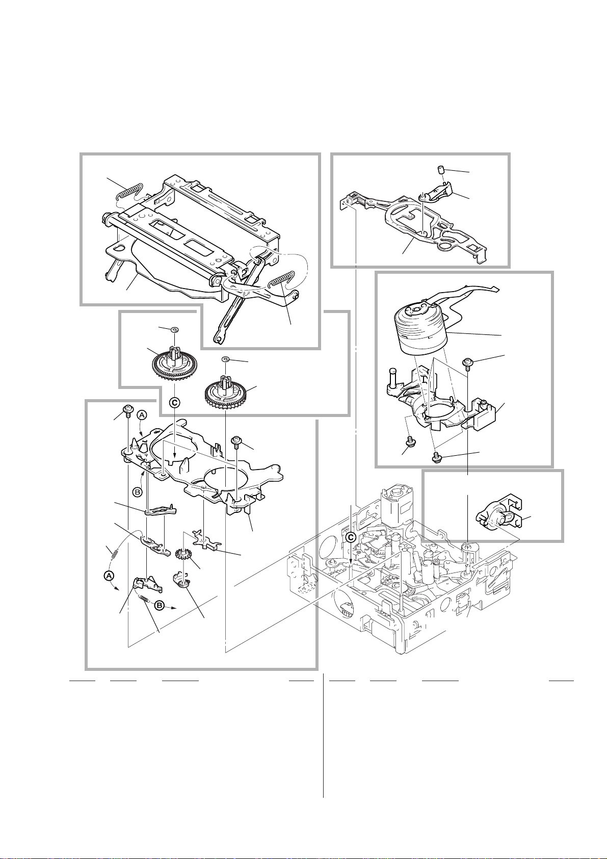
1-1. CASSETTE COMPARTMENT, DRUM AND REEL TABLE ASSEMBLY
714
Refer to page 9 for details of
replacement of parts.
715
Refer to page 8 for details of
replacement of parts.
719
Refer to page 8 for details of replacement of parts.
718
707
713
714
M901(Note)
712
713
710
711
Refer to page 10 for details
of replacement of parts.
717
710
710
710
Refer to page 9 for details of
replacement of parts.
710
709
708
701
705
716
704
703
706
702
701
Refer to pages 10 and 15 for details of replacement of parts.
Ref. No. Part No. Description Remark Ref. No. Part No. Description Remark
701 3-988-312-01 SPRING, EXTENSION
702 3-988-220-01 BRAKE (T)
703 3-988-221-01 GEAR (T), BRAKE
704 3-988-222-01 SPRING (T), BRAKE
705 3-988-215-02 BASE, CASSETTE
711 X-3948-445-1 TABLE (T) ASSY, REEL
712 X-3948-444-1 TABLE (S) ASSY, REEL
713 3-989-465-01 WASHER, STOPPER
714 3-988-298-01 SPRING EXTENSION
715 X-3948-441-2 CASSETTE COMPARTMENT ASSY
Note
:Refer to the proper service manual
since the model name of drum assembly and the Parts No. are different according to sets.
706 3-988-217-01 ARM (S), RESET
707 3-988-281-02 ARM, HC
708 3-988-219-01 RACK (S), BRAKE
709 3-988-218-01 BRAKE (S)
710 3-947-503-01 SCREW (M1.4X2.5)
716 X-3948-443-2 DAMPER ASSY
717 A-7093-612-A DRUM BASE BLOCK ASSY
718 3-988-282-01 ROLLER, HC
719 3-988-283-01 STOPPER, TAPE FALL
M901
Note
DRUM ASSY
– 3 –
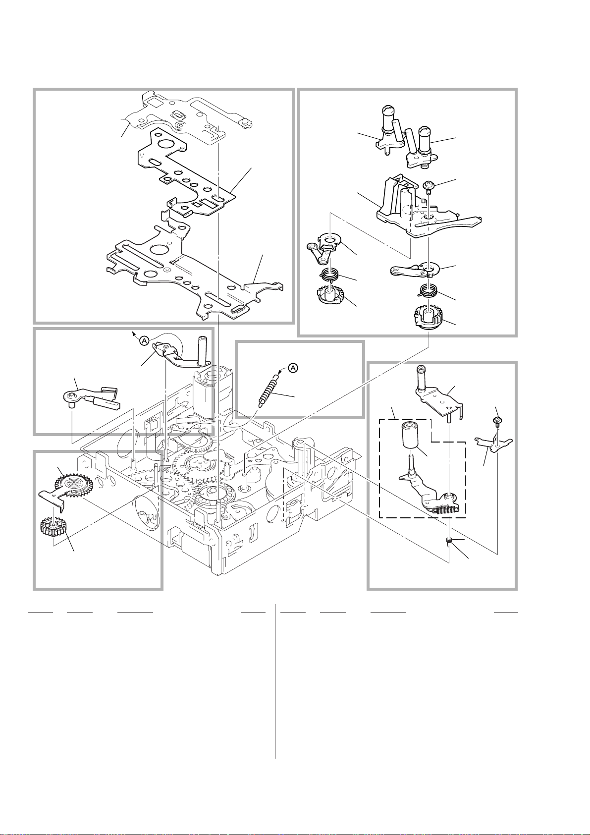
1-2. TAPE GUIDE, PINCH SLIDER ASSEMBLY AND BRAKE SLIDER ASSEMBLY
Refer to pages 12 and 16 for details of replacement of parts.
Including Ref No.
on page 5.
Refer to page 11 for details of replacement
of parts.
Refer to page 11 for details
of replacement of parts.
753
813
754
756
755
Refer to page 11 for details of
replacement of parts.
757
770
768
766
764
762
759
769
767
765
763
761
760
773
752
772
771
751
Refer to page 10 for details of
replacement of parts.
Ref. No. Part No. Description Remark Ref. No. Part No. Description Remark
751 3-988-263-01 GEAR, RELAY
752 X-3948-442-2 GEAR ASSY, GOOSENECK
753 X-3948-435-2 PLATE ASSY, TG1 ADJUSTMENT
754 X-3948-434-1 ARM ASSY, TG1
755 X-3948-428-4 SLIDER ASSY, PINCH
756 X-3948-766-1 SLIDER ASSY, BRAKE
757 3-988-270-01 SPRING (TG1), TENSION COIL
758 3-988-233-01 SPRING (TG7LD), TORSION
759 X-3948-433-2 ARM ASSY, PINCH
760 A-7093-501-A ARM BLOCK ASSY, TG7
761 3-988-257-02 GEAR (T), GL
762 3-988-252-03 GEAR (S), GL
763 3-988-258-01 SPRING (GLT), TORSION
764 3-988-253-01 SPRING (GLS), TORSION
765 X-3948-440-1 ARM (T) ASSY, GL
766 X-3948-439-3 ARM (S) ASSY, GL
767 3-947-503-01 SCREW (M1.4X2.5)
768 3-988-242-01 RAIL, GUIDE
769 X-3948-438-3 COASTER (T) ASSY
770 X-3948-437-1 COASTER (S) ASSY
771 3-988-690-02 SPRING, TG7 RETAINER
772 X-3748-630-2 ROLLER ASSY (DIA. 5.6), PINCH
773 3-050-334-01 SCREW (M1.4X5)
Refer to pages 11 and 12 for details of
replacement of parts.
758
– 4 –
Ver 1.1 1999.10
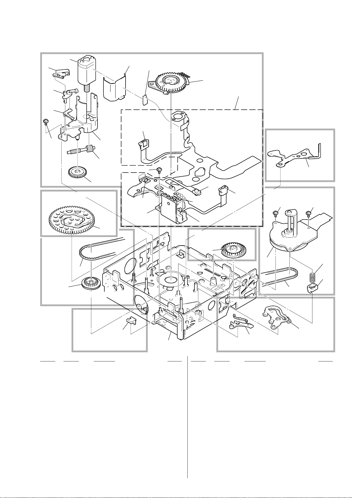
1-3. EACH GEARS AND LOADING / CAPSTAN MOTOR ASSEMBLY
M902
810
809
808
807
806
805
804
Refer to page 11 for details of
replacement of parts.
803
811
Q901
807
H901
CN901
812
Refer to pages 14 and 17 for details of
replacement of parts.
S903
813
D901
Q902
H902
S902
Refer to page 12 for details of
replacement of parts.
Refer to page 12 for details of
replacement of parts.
814
Refer to page 13 for details of
replacement of parts.
807
807
802
801
Refer to page 13 for details of
replacement of parts.
S901
Refer to page 14 for details of
replacement of parts.
Ref. No. Part No. Description Remark
801 3-988-274-01 PULLEY, CONVERSION
802 3-988-276-02 BELT, TIMING
803 3-988-216-01 GEAR, CAM
804 3-988-211-01 GEAR, DECELERATION
805 3-988-210-01 SHAFT, WORM
806 3-988-207-01 HOLDER, MOTOR
807 3-947-503-01 SCREW (M1.4X2.5)
808 3-988-303-01 ARM, SPRING HOOK DRIVING
809 3-988-271-01 BASE, SPRING HOOK FULCRUM
810 3-988-302-01 HOOK, TG1 SPRING
818
815
M903
820
819
802
817
816
Ref. No. Part No. Description Remark
816 3-988-223-01 ARM, EJECT
817 3-988-224-01 ARM, PINCH PRESS
818 X-3948-431-4 CHASSIS ASSY
819 3-050-170-01 HOLDER
820 3-051-787-02 SPRING (CAP), COMPRESSION COIL
CN901 1-784-723-11 PIN, CONNECTOR 4P
D901 8-719-067-13 DIODE GL453K
H901 8-719-061-28 DIODE HW-105C-FT-V (S REEL SENSOR)
H902 8-719-061-28 DIODE HW-105C-FT-V (T REEL SENSOR)
M901 X-3948-346-1 MOTOR ASSY, L (LOADING)
Refer to page 12 for details of
replacement of parts.
811 3-988-208-01 SHIELD, MOTOR
812 1-657-785-11 FP-248 FLEXIBLE BOARD (DEW SENSOR)
813 A-7073-418-A FP-594 BOARD, COMPLETE
814 3-988-280-03 ARM, HC DRIVING
815 3-988-239-01 GEAR, GL DRIVING
M903 8-835-606-01 MOTOR, DC SCD15A/C-NP (CAPSTAN)
Q901 8-729-907-25 PHOTO TRANSISTOR PT4850F (TAPE END)
Q902 8-729-907-25 PHOTO TRANSISTOR PT4850F (TAPE TOP)
S901 1-771-039-51 SWITCH, PUSH (C IN SW)
S902 1-572-719-32 SWITCH, PUSH (1 KEY) (REC PROOF)
S903 1-771-325-11 ENCODER, ROTARY (SWITCH) (MODE)
– 5 –
2. PARTS REPLACEMENT AND PREPARATION FOR ADJUSTMENT
• About Mode Selector II
2-1. OUTLINE
This unit is a mechanism drive tool which supplements the
maintenance of each mechanism deck. Its functions are
described below.
1. Manual test
A mode which drives the motor only while the switch is ON.
It enables the operator to control the motor as desired.
2. Step test
A mode which drives the motor until the current condition
detected by the sensor changes to another condition. It enables
the movements made by the motor in each operation to be
controlled while being checked.
3. Auto test
A mode that checks if the mechanism operates normally
according to the condition shift table recorded in the unit for
each mechanism deck. All the conditions of the decks are checked
through a series of operations.
An error message is displayed if incorrect shifts and conditions
are detected and operations are stopped.
2-2. MECHANISM CONDITION (POSITION)
SHIFTING ORDER LIST
After selecting the mechanism deck, select one of the two test
modes other than the auto test, and press the RVS and FF button
to specify the mechanism state (position).
MD name
Code
ABCD
1110
1010
1011
1001
0111
0011
1101
1100
1
2
3
4
5
6
7
8
C mechanism
EJECT
ULE
SR
HL
LE
STOP
RP
REW
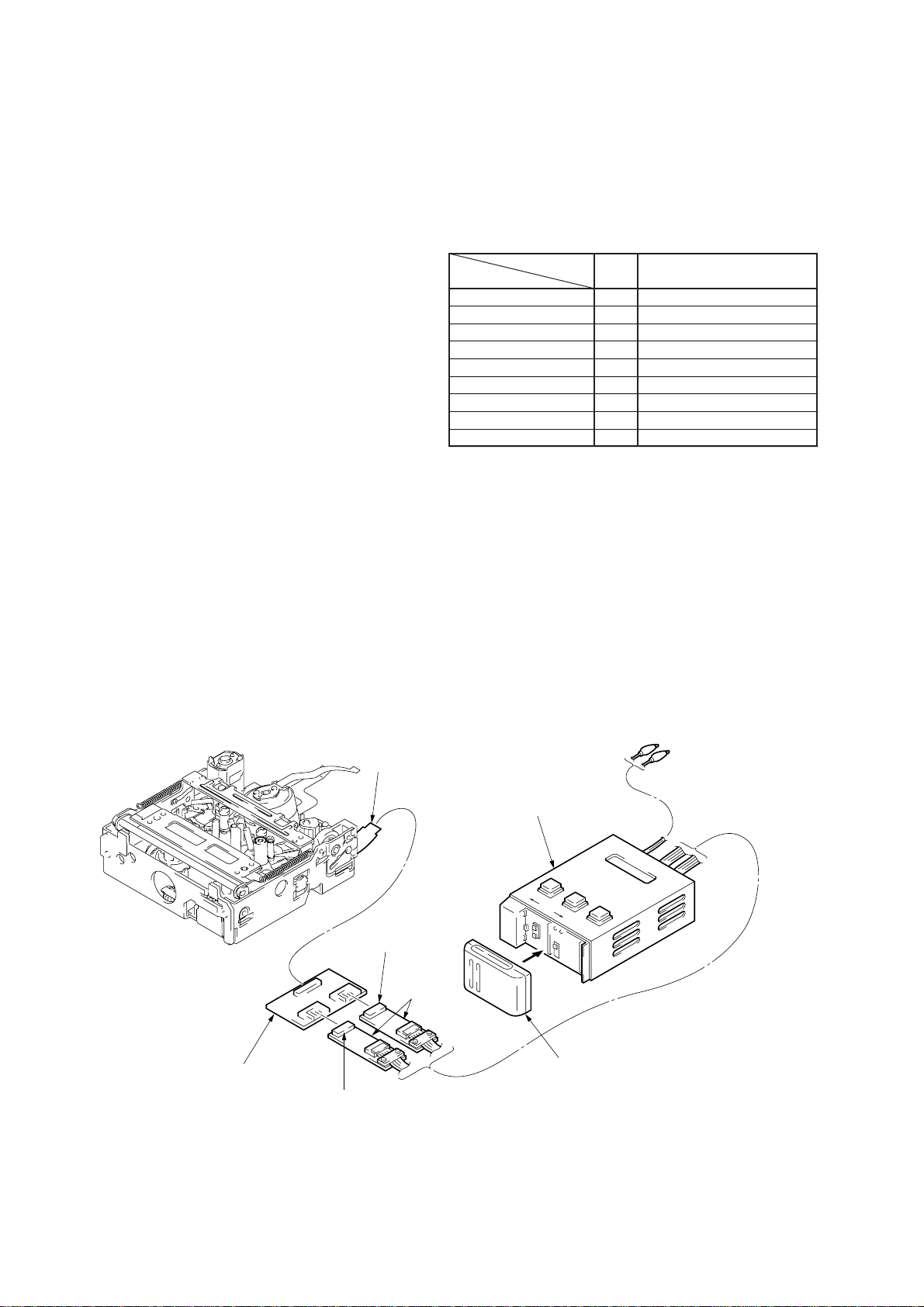
2-3. MODE SELECTOR II (A-6082-282-A) CONNECTION
C mechanism
Mode selector conversion
board (C)
Connector (Black) 6P
FP-594 flexible board
Connector (White) 6P
Relay boards
Mode serector
Battery of NP-55, 77, etc.
(Power supply)
Alligator Clip
II
– 6 –
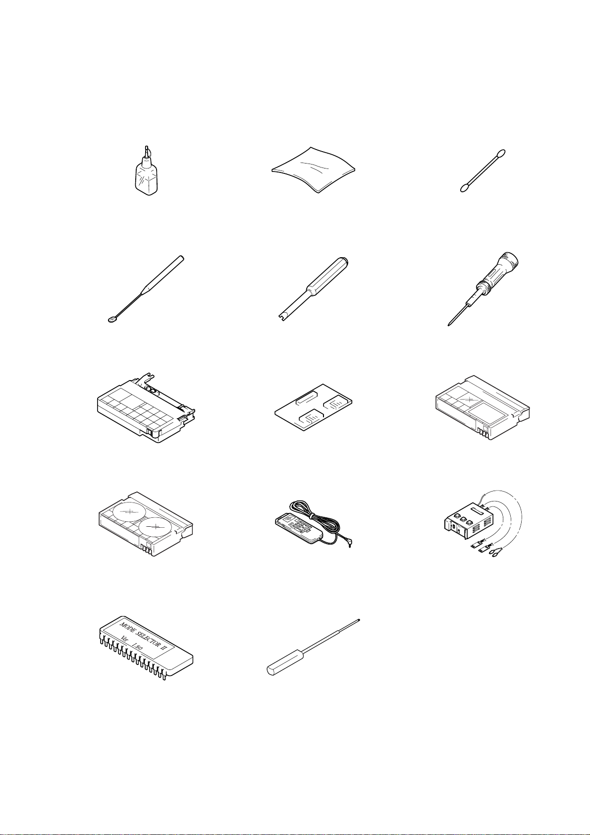
2-4. SERVICE JIGS LIST
J-1. Cleaning fluid
(Y-2031-001-0)
J-4. Mirror (Small oval type)
(J-6082-840-A)
J-7. TG1 adjustment jig
(FWD position adjustment)
(J-6082-420-A)
J-2. Wiping cloth
(7-741-900-53)
J-5. Screwdriver for tape path
(J-6082-026-A)
J-8. Mode selector conversion board (C)
(J-6082-417-A)
J-3. Super fine applicator
(Made by NIPPON APPLICAT OR(P752D))
J-6. Torque driver
(J-9049-330-A)
J-9. Tracking tape (XH2-1) (NTSC/PAL)
(8-967-997-01)
J-10. Mini DV torque cassette
(J-6082-360-A)
II
J-13. Mode selector
(Corresponds to C mechanism: Note 2)
(J-6082-314-D)
ROM
J-11. Adjusting remote commander
(RM-95 remodeled partly : Note 1)
(J-6082-053-B)
J-14. Bending stick
(J-6082-419-A)
Note 1 : If the micro processor IC in the adjusting remote com-
Note 2 :ROM for version upgrading to allow use of the mode se-
J-12. Mode selector
(J-6082-282-A)
II
mander is not the new micro processor (UPD7503G-C56-
12), the pages cannot be switched. In this case, replace
with the new micro processor (8-759-148-35).
lector II with the C mechanism.
– 7 –
Screw tightening torque tolerance.
1
3
4
2
3
3
0.0098 N.m (0.1 kg.cm)
3. PARTS REPLACEMENT
• Precautions
For details on removing the cabinet and board, refer to "DISASSEMBL Y" in the respective service manuals. For details on the replacement
of mechanism parts (removal or attaching), refer to the respective flowcharts, and perform the procedure given.
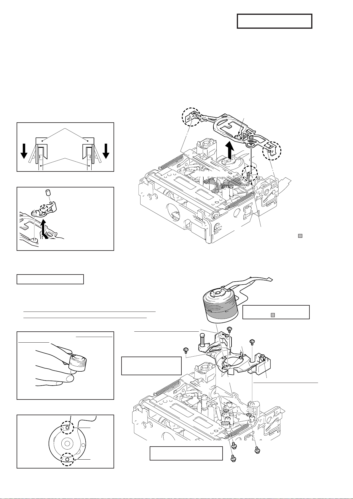
3-1. TAPE FALL STOPPER, HC ROLLER AND HC ARM
Removing method :Spread out the left and right attaching parts
and remove them upwards.
Attaching method : Refer to the Details diagram.
Details diagram on attachment of Tape
Fall Stopper
The left and right attaching parts are fixed to
the chassis.
Chassis
Spread outwards.
Tape fall stopper
HC arm
Spread outwards.
Details diagram on removal and
attachment of HC Arm and HC Roller
HC roller
Claw
HC arm
Rotate slightly and
release the lock.
Tape fall stopper
Note:There should be no scratches
or dirt on the HC roller.
3-2. DRUM ASSEMBLY AND DRUM BASE BLOCK ASSEMBLY
Remove the
“3-1. Tape Fall Stopper”.
Removing method : Remove in the order of 1/2/3/4 .
Attaching method : Attach in the order of 4/3/2/1 .
(Note:Tighten the screws in the order of A, B, and C.)
After attaching all the parts, refer to the flowchart on page 18,
and perform the adjustments from Starting adjustments-2.
Holding the Drum Assembly
Insert your second finger between the two
flexible boards, and hold the top and bottom
boards.
Note:Do not touch the running face of the
Details diagram on attachment of Drum
drum assembly.
Blast screw (Do not rotate.)
Drum base block assembly
tightening torque
0.0686 N•m (0.7 kg•cm)
Assembly (Positioning pins)
Drum assembly
B
Screw
HC driving arm
Positioning pins
When attaching the tape fall stopper,
make sure that the HC arm (
outside the HC driving arm (capstan
motor side).
Do not touch the running face
A
Screw
of the tape (
C
Drum base block assembly
).
Screw
Blast screw (Do not rotate.)
) is
Pin at rear side
Pin at side of
reel table
Long hole
Hole
Drum assembly tightening torque
0.0588 N•m (0.6 kg•cm)
– 8 –
C
B
Screw
Screw
A
Screw
 Loading...