

Sony MDXCA-580 Service manual
MDX-CA580
p
p
SERVICE MANUAL
Ver 1.1 2001.05
U.S. and foreign patents licensed from Dolby laboratories
Licensing Corporation.
SPECIFICATIONS
AEP Model
UK Model
Model Name Using Similar Mechanism NEW
Base Mechanism Type MG-164NA-138
Optical Pick-up Name KMS-241C
MD player section
Signal-to-noise ratio 90 dB
Frequency response 10 – 20,000 Hz
Wow and flutter Below measurable limit
Tuner section
FM
Tuning range 87.5 – 108.0 MHz
Aerial terminal External aerial connector
Intermediate frequency 10.7 MHz/450 kHz
Usable sensitivity 8 dBf
Selectivity 75 dB at 400 kHz
Signal-to-noise ratio 66 dB (stereo),
Harmonic distortion at 1 kHz
Separation 35 dB at 1 kHz
Frequency response 30 – 15,000 Hz
MW/LW
Tuning range MW: 531 – 1,602 kHz
Aerial terminal External aerial connector
Intermediate frequency 10.7 MHz/450 kHz
Sensitivity MW: 30 µV
Power amplifier section
Outputs Speaker outputs
Speaker impedance 4 – 8 ohms
Maximum
ower out
72 dB (mono)
0.6 % (stereo),
0.3 % (mono)
LW: 153 – 279 kHz
LW: 40 µV
(sure seal connectors)
ut 50 W × 4 (at 4 ohms)
General
Outputs Audio outputs
Tone controls Bass ±9 dB at 100 Hz
Power requirements 12 V DC car battery
Dimensions Approx. 178 × 50 × 183 mm
Mounting dimensions Approx. 182 × 53 × 162 mm
Mass Approx. 1.2 kg
Supplied accessories Parts for installation and
Design and specifications are subject to change
without notice.
Power aerial relay control
lead
Power amplifier control
lead
Telephone ATT control
lead
Treble ±9 dB at 10 kHz
(negative ground)
(w/h/d)
(w/h/d)
connections (1 set)
Front panel case (1)
FM/MW/LW MINIDISC PLAYER
9-870-228-12 Sony Corporation
2001E0500-1 e Vehicle Company
C 2001.5 Shinagawa Tec Service Manual Production Group
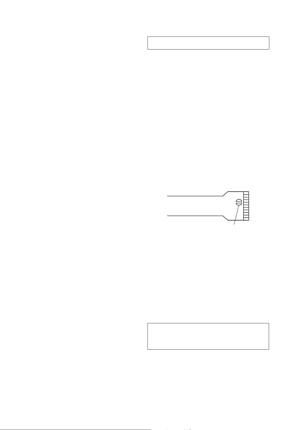
TABLE OF CONTENTS
1. GENERAL
Location of Controls ....................................................... 3
Setting the Clock ............................................................. 3
Installation....................................................................... 4
Connections ..................................................................... 5
2. DISASSEMBLY ......................................................... 9
3. ELECTRICAL ADJUSTMENTS
Test Mode........................................................................ 16
MD Section ..................................................................... 16
Tuner Section .................................................................. 16
4. DIAGRAMS
4-1. Block Diagram – SERVO Section – ............................... 17
4-2. Block Diagram – TUNER Section – .............................. 18
4-3. Block Diagram – MAIN Section – ................................. 19
4-4. Block Diagram – BUS CONTROL/
POWER SUPPLY Section – ........................................... 20
4-5. Note for Printed Wiring Boards and
Schematic Diagrams ....................................................... 22
4-6. Printed Wiring Boards – SERVO Section – ................... 23
4-7. Schematic Diagram – SERVO Section (1/2) –............... 24
4-8. Schematic Diagram – SERVO Section (2/2) –............... 25
4-9. Printed Wiring Board
– MAIN Board (Component Side) – .............................. 26
4-10. Printed Wiring Board
– MAIN Board (Conductor Side) – ................................ 27
4-11. Schematic Diagram – MAIN Board (1/3) – ................... 28
4-12. Schematic Diagram – MAIN Board (2/3) – ................... 29
4-13. Schematic Diagram – MAIN Board (3/3) – ................... 30
4-14. Printed Wiring Board – SUB Board – ............................ 32
4-15. Schematic Diagram – SUB Board – ............................... 33
4-16. Printed Wiring Board – KEY Board –............................ 34
4-17. Schematic Diagram – KEY Board – .............................. 35
4-18. IC Pin Function Description ........................................... 40
5. EXPLODED VIEWS................................................ 50
6. ELECTRICAL PARTS LIST ............................... 54
NOTES ON HANDLING THE OPTICAL PICK-UP
BLOCK OR BASE UNIT
The laser diode in the optical pick-up block may suffer electrostatic break-down because of the potential difference generated
by the charged electrostatic load, etc. on clothing and the human
body.
During repair, pay attention to electrostatic break-down and also
use the procedure in the printed matter which is included in the
repair parts.
The flexible board is easily damaged and should be handled with
care.
NOTES ON LASER DIODE EMISSION CHECK
Never look into the laser diode emission from right avove when
checking it for adustment. It is feared that you will lose your sight.
NOTES ON HANDLING THE OPTICAL PICK-UP BLOCK
(KMS-241C).
The laser diode in the optical pick-up block may suffer electrostatic break-down easily. When handling it, perform soldering
bridge to the laser-tap on the flexible board. Also perform
m easur es against electrostatic break-down suff iciently before the
operation. The flexible board is easily damaged and should be
handled with care.
laser-tap
OPTICAL PICK-UP FLEXIBLE BOARD
Notes on chip component replacement
• Never reuse a disconnected chip component.
• Notice that the minus side of a tantalum capacitor may be damaged by heat.
Flexible Circuit Board Repairing
• Keep the temperature of the soldering iron around 270 ˚C during repairing.
• Do not touch the soldering iron on the same conductor of the
circuit board (within 3 times).
• Be careful not to apply force on the conductor when soldering
or unsoldering.
CAUTION
Use of controls or adjustments or performance of procedures
other than those specified herein may result in hazardous radiation exposure.
SAFETY-RELATED COMPONENT WARNING!!
COMPONENTS IDENTIFIED BY MARK 0 OR DOTTED
LINE WITH MARK 0 ON THE SCHEMATIC DIAGRAMS
AND IN THE PARTS LIST ARE CRITICAL TO SAFE
OPERATION. REPLACE THESE COMPONENTS WITH
SONY PARTS WHOSE PART NUMBERS APPEAR AS
SHOWN IN THIS MANUAL OR IN SUPPLEMENTS PUBLISHED BY SONY.
2
SECTION 1
GENERAL
This section is extracted from
instruction manual.
Location of controls
PTY
S
+
C
I
D
MENU
SOURCE
SOUND
P
R
S
T
-
-
D
I
S
OFF
Refer to the pages listed for details.
1 Volume control dial 19
2 MENU button 8, 10, 12, 13, 14, 15, 16,
18, 19, 21, 24
3 DISC/PRST +/– (cursor up/down) buttons
8, 10, 12, 13, 14, 15, 16, 18, 19, 20, 21, 24
During CD/MD playback:
Disc change 10, 13
During radio reception:
Preset stations select 16
Z (eject) button (located on the front
4
side of the unit behind the front panel)
9
5 DSPL/PTY (display mode change/
programme type) button 9, 10, 12, 17,
20
6 LIST button 12
List-up 13
7 SOURCE (TUNER/CD/MD) button
8, 9, 10, 13, 15, 16, 19
8 Display window
9 OPEN button 7, 9, 26
q; D-BASS button 25
qa SOUND button 23
qs Reset button (located on the front side
of the unit behind the front panel) 7
qd OFF button* 7, 8, 9
DSPL
-
P
R
S
T
+
LIST
-
SEEK/AMS
ENTER
–
C
MODE
OPEN
D-BASS
AF
REP SHUF
1 2 3 4 56
qf SEEK/AMS –/+ (cursor left/right) buttons
8, 10, 12, 14, 16, 18, 19, 21, 23, 24
Automatic Music Sensor 10, 14
Manual Search 10
Seek 15, 16, 18
qg ENTER button 8, 10, 12, 13, 14, 15, 16,
18, 19, 20, 21, 24
qh MODE button 19
During CD or MD playback:
CD/MD unit select 9, 13
During radio reception:
BAND select 15, 16
qj Receptor for the card remote
commander
qk Number buttons
During radio reception:
Preset number select 15, 16, 18, 19
During CD/MD playback:
(1) REP 11
(2) SHUF 11
ql AF button 17, 18, 19
w; TA button 18, 19
* Warning when installing in a car
without ACC (accessory) position on
the ignition key switch
Be sure to press (OFF) on the unit for two
seconds to turn off the clock display after
turning off the engine.
When you press (OFF) only momentarily,
the clock display does not turn off and this
causes battery wear.
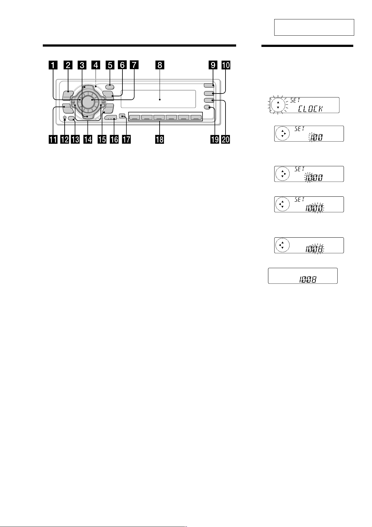
Setting the clock
The clock uses a 24-hour digital indication.
Example: To set the clock to 10:08
1
Press (MENU), then press either side of
(DISC/PRST) repeatedly until “CLOCK”
appears.
TA
1 Press (ENTER).
The hour indication flashes.
2 Press either side of (DISC/PRST) to set
the hour.
3 Press the (+) side of (SEEK/AMS).
The minute indication flashes.
4 Press either side of (DISC/PRST) to set
the minute.
2
Press (ENTER).
The clock starts.
After the clock setting is completed, the
display returns to normal play mode.
Tip
You can set the clock automatically with the RDS
feature (see page 17).
Note
When the D.INFO mode is set to ON, the time is
always displayed, provided that the M.DSPL is set
to OFF (page 24).
3
Installation
Installation
Installation
Installazione
Montage
Precautions
• Choose the installation location carefully
so that the unit will not interfere with
normal driving operations.
• Avoid installing the unit in areas subject
to dust, dirt, excessive vibration, or high
temperature, such as in direct sunlight or
near heater ducts.
• Use only the supplied mounting
hardware for a safe and secure
installation.
Mounting angle adjustment
Adjust the mounting angle to less than 20°.
How to detach and attach
the front panel
Before installing the unit, detach the
front panel.
A To detach
Before detaching the front panel, be sure to
press (OFF). Press (OPEN), then slide the
front panel to the right side, and pull out
the left side.
B To attach
Place the hole
the spindle
then push the left side in.
in the front panel onto
on the unit as illustrated,
A
1
2
Vorsichtsmaßnahmen
• Wählen Sie den Einbauort sorgfältig so
aus, daß das Gerät beim Fahren nicht
hinderlich ist.
• Bauen Sie das Gerät so ein, daß es keinen
hohen Temperaturen (keinem direkten
Sonnenlicht, keiner Warmluft von der
Heizung), keinem Staub, keinem Schmutz
und keinen starken Vibrationen
ausgesetzt ist.
• Für eine sichere Befestigung verwenden
Sie stets nur die mitgelieferten
Montageteile.
Hinweis zum Montagewinkel
Das Gerät sollte in einem Winkel von
weniger als 20° montiert werden.
Abnehmen und Anbringen
der Frontplatte
Nehmen Sie die Frontplatte vor dem
Einbau des Geräts ab.
A Abnehmen
Drücken Sie auf jeden Fall (OFF), bevor Sie
die Frontplatte abnehmen. Drücken Sie
(OPEN), schieben Sie dann die Frontplatte
nach rechts, und ziehen Sie sie an der linken
Seite heraus.
B Anbringen
Setzen Sie die Aussparung der
Frontplatte auf die Spindel
wie in der Abbildung zu sehen, und
drücken Sie dann die linke Seite an.
am Gerät auf,
Précautions
• Choisir soigneusement l’emplacement de
l’installation afin que l’appareil ne gêne
pas la conduite normale du véhicule.
• Eviter d’installer l’appareil dans un
endroit exposé à des températures
élevées, comme en plein soleil ou à
proximité d’une bouche d’air chaud, ou à
de la poussière, saleté ou vibrations
violentes.
• Pour garantir un montage sûr, n’utiliser
que le matériel fourni.
Réglage de l’angle de montage
Ajuster l’inclinaison à un angle inférieur à
20°.
Retrait et pose de la
façade
Avant d’installer l’appareil, déposer la
façade.
A Pour retirer
Avant de retirer la façade, ne pas oublier
d’appuyer d’abord sur (OFF). Appuyer
sur (OPEN), puis faire glisser la façade vers
la droite et la retirer par la gauche.
B Pour attacher
Fixez la partie de la façade sur la partie
de l’appareil, comme indiqué sur
l’illustration, puis appuyez sur le côté
gauche jusqu’au déclic.
B
Precauzioni
• Scegliere con attenzione la posizione per
l’installazione in modo che l’apparecchio
non interferisca con le operazioni di
guida del conducente.
• Evitare di installare l’apparecchio dove
sia soggetto ad alte temperature, come
alla luce solare diretta o al getto di aria
calda dell’impianto di riscaldamento, o
dove possa essere soggetto a polvere,
sporco e vibrazioni eccessive.
• Usare solo il materiale di montaggio in
dotazione per un’installazione stabile e
sicura.
Regolazione dell’angolo di montaggio
Regolare l’angolo di montaggio in modo
che sia inferiore a 20°.
Come rimuovere e
reinserire il pannello
anteriore
Prima di installare l’apparecchio
rimuovere il pannello anteriore.
A Per rimuoverlo
Prima di rimuovere il pannello anteriore,
assicurarsi di premere (OFF). Premere
(OPEN), quindi far scivolare il pannello
anteriore verso destra e tirare il lato sinistro
verso di sé.
B Per reinserirlo
Applicare la foro del pannello anteriore
al mandrino
mostrato nell’illustrazione e premere il lato
sinistro fino a sentire uno scatto.
dell’apparecchio come
c
Voorzorgsmaatregelen
• Kies de installatieplaats zorgvuldig zodat
het toestel de bestuurder niet hindert
tijdens het rijden.
• Installeer het apparaat niet op plaatsen
waar het blootgesteld wordt aan hoge
temperaturen, b.v. in direct zonlicht of bij
de warme luchtstroom van de
autoverwarming, aan sterke trillingen, of
waar het in contact komt met veel stof of
vuil.
• Gebruik voor het veilig en stevig
monteren van het apparaat uitsluitend de
bijgeleverde montage-onderdelen.
Maximale montagehoek
Installeer het apparaat nooit onder een hoek
van meer dan 20° met het horizontale vlak.
Verwijderen en bevestigen
van het afneembare
voorpaneel
Verwijder, alvorens met het installeren
te beginnen, het afneembare
voorpaneel.
A Verwijderen
Druk eerst op (OFF) alvorens het
voorpaneel los te maken. Druk op (OPEN),
schuif het voorpaneel naar rechts en trek
het los aan de linkerkant.
B Bevestigen
Breng deel van het voorpaneel aan op
deel
van het apparaat zoals afgebeeld en
druk op de linkerzijde tot deze vastklikt.
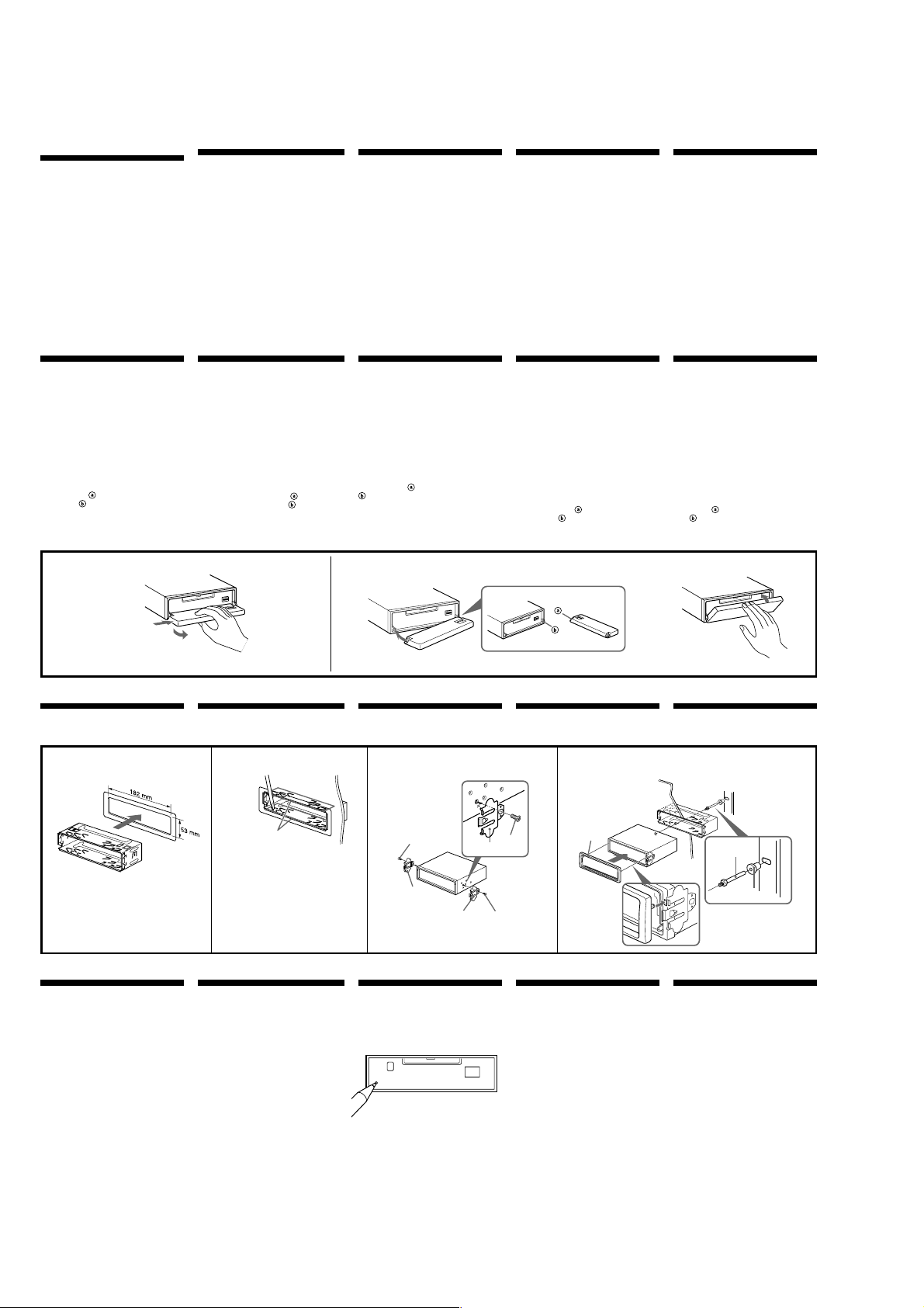
Installation in the
dashboard
Installation im
Armaturenbrett
Installation dans le tableau
de bord
1 2 3
Bend these claws outward for a
tight fit, if necessary.
1
Reset button
When the installation and connections are
completed, be sure to press the reset button
with a ballpoint pen, etc.
Falls erforderlich, diese Klammern
für einen sicheren Halt nach außen
biegen.
Plier ces griffes pour assurer une
prise correcte si nécessaire.
Piegare questi morsetti per
un‘installazione più sicura, se
necessario.
Indien nodig kunt u deze lipjes
ombuigen voor een steviger
bevestiging.
Rücksetztaste
Nach der Installation und dem Anschluß
muß die Rücksetztaste mit einem
Kugelschreiber o. ä. gedrückt werden.
Touche de réinitialisation
Quand l’installation et les connexions sont
terminées, appuyer sur la touche de
réinitialisation avec un stylo à bille, etc.
Montage in het dashboardInstallazione nel cruscotto
Fire wall
Dashboard
4
Armaturenbrett
Tableau de bord
Cruscotto
Dashboard
1
5
5
7
4
7
7
5
Tasto di azzeramento
Dopo avere terminato l’installazione e i
collegamenti, assicurarsi di premere il tasto
di azzeramento con la punta di una penna
a sfera o un oggetto simile.
Terugsteltoets
Druk, nadat u het apparaat heeft
geïnstalleerd en de aansluitingen heeft
gemaakt, met een balpen of een ander
puntig voorwerp op de terugsteltoets.
Motorraumtrennwand
Paroi ignifuge
Parete frangifiamma
Brandschot
2
3
4

Connexions
Précautions
• Cet appareil est conçu pour fonctionner
sur courant continu de 12 V avec masse
négative.
• Veiller à ne pas coincer de fils entre une
vis et la carrosserie de la voiture ou cet
appareil ou encore entre des pièces
mobiles comme les glissières des sièges,
etc.
• Brancher le cordon d’alimention 8 sur
l’appareil et les haut-parleurs avant de le
brancher sur le connecteur d’alimentation
auxiliaire.
• Rassembler tous les fils de terre en un
point de masse commun.
• Brancher le câble jaune à un circuit libre
de la voiture dont la capacité nominale
est supérieure à la capacité du fusible de
l’appareil. Si vous branchez cet appareil
en série avec d’autres composants stéréo,
le circuit de la voiture auquel ils sont
raccordés doit afficher une capacité
nominale supérieure à la somme des
capacités individuelles de chaque
composant. S’il n’y a pas de circuits de
voiture affichant une capacité égale à la
capacité du fusible de l’appareil, brancher
l’appareil directement à la batterie. Si
aucun circuit de voiture n’est disponible
pour connecter cet appareil, brancher
l’appareil à un circuit de voiture
supérieur à la capacité du fusible de
l’appareil de telle sorte que si l’appareil
grille son fusible, aucun autre circuit ne
soit coupé.
Anschluß
Vorsicht
• Dieses Gerät ist ausschließlich für den
Betrieb bei 12 V Gleichstrom (negative
Erdung) bestimmt.
• Achten Sie darauf, keine Kabel zwischen
einer Schraube und der Karosserie oder
diesem Gerät oder zwischen beweglichen
Teilen wie den Sitzschienen usw.
einzuklemmen.
• Verbinden Sie das Stromversorgungskabel
8 mit dem Gerät und den Lautsprechern,
bevor Sie es mit dem Hilfsstromanschluß
verbinden.
• Schließen Sie alle Erdungskabel an
einen gemeinsamen Massepunkt an.
• Schließen Sie das gelbe Kabel an einen
freien Autostromkreis mit höherer
Leistung als der der Gerätesicherung an.
Wenn Sie dieses Gerät zusammen mit
anderen Stereokomponenten anschließen,
muß der Autostromkreis, an den die
Geräte angeschlossen sind, eine höhere
Leistung aufweisen als die Summe der
Sicherungen der einzelnen Komponenten.
Wenn kein Autostromkreis eine so hohe
Leistung aufweist wie die Sicherung des
Geräts, schließen Sie das Gerät direkt an
die Batterie an. Wenn kein Autostromkreis
zum Anschließen dieses Geräts frei ist,
schließen Sie das Gerät an einen
Autostromkreis mit höherer Leistung als
der der Gerätesicherung an, und zwar so,
daß keine anderen Stromkreise
unterbrochen werden, wenn die
Sicherung durchbrennen sollte.
Aansluitingen
Let op!
• Dit apparaat is ontworpen voor gebruik
op gelijkstroom van een 12 Volts autoaccu, negatief geaard.
• Zorg ervoor dat er geen snoeren geklemd
zitten tussen een schroef en het
koetswerk, het toestel of bewegende
onderdelen zoals de zetelrail, enz.
• Sluit het netsnoer 8 aan op het toestel en
de luidsprekers vooraleer u het op de
hulpvoedingsaansluiting aansluit.
• Sluit alle aarddraden op een
gemeenschappelijk aardpunt aan.
• Sluit het gele snoer aan op een vrij
autocircuit met een capaciteit die hoger
ligt dan die van de toestelzekering. Als u
dit toestel in serie schakelt met andere
audiocomponenten, moet de capaciteit
van het autocircuit waarop ze zijn
aangesloten hoger zijn dan de som van
de zekeringcapaciteit van elke
component afzonderlijk. Als er geen
autocircuits een even hoge capaciteit
hebben als de toestelzekering, moet het
toestel rechtstreeks worden aangesloten
op de accu. Als er geen autocircuits
beschikbaar zijn om dit toestel aan te
sluiten, moet u het toestel aansluiten op
een autocircuit met een hogere capaciteit
dan die van de toestelzekering. Indien de
toestelzekering dan doorbrandt, worden
geen andere circuits onderbroken.
Collegamenti
Attenzione
• Questo apparecchio è stato progettato per
l’uso solo a 12 V CC con massa negativa.
• Far attenzione che i cavi non rimangano
impigliati tra la vite e la carrozzeria della
macchina o l’apparecchio o tra le parti
mobili della macchina, come le guide di
scorrimento del sedile, ecc.
• Collegare il cavo di collegamento
dell’alimentazione 8 all’apparecchio e ai
diffusori prima di collegarlo al connettore
di alimentazione ausiliaria.
• Portare tutti i cavi di massa a un punto
di massa comune.
• Collegare il cavo giallo a un circuito
libero della macchina con potenza
nominale superiore a quella del fusibile
dell’apparecchio. Se si collega questo
apparecchio in serie con altri componenti
stereo, il circuito della macchina a cui
sono collegati deve avere una potenza
nominale superiore alla somma della
potenza nominale dei fusibili di ogni
componente. Se i circuiti della macchina
non hanno potenza nominale superiore a
quella dei fusibili, collegare l’apparecchio
direttamente alla batteria. Se non si
hanno a disposizione circuiti della
macchina per collegare l’apparecchio,
collegare l’apparecchio a un circuito della
macchina con potenza nominale
superiore a quella del fusibile
dell’apparecchio in modo tale che, se il
fusibile dell’apparecchio salta, gli altri
circuiti non verranno tagliati fuori.
Remarques sur l’exemple
de connexion
Remarques sur les fils de commande
et d’alimentation
• Le fil de commande (bleu) de l’antenne
électrique assure une alimentation de
+12 V CC lorsque vous mettez le
syntoniseur sous tension ou lorsque vous
activez la fonction AF (fréquence
secondaire) ou TA (informations
routières).
• Une antenne électrique sans boîtier de
relais ne peut pas être utilisée avec cet
appareil.
• Si votre voiture est équipée d’une
antenne FM/MW/LW intégrée dans la
vitre arrière/latérale, il est nécessaire de
raccorder le fil de commande de
l’antenne électrique (bleu) ou le fil
d’entrée d’alimentation des accessoires
(rouge) de l’amplificateur d’antenne
existant. Pour plus de détails, consultez
votre revendeur.
Avertissement
Si vous disposez d’une antenne électrique
sans boîtier de relais, le branchement de cet
appareil au moyen du cordon
d’alimentation fourni 8 risque
d’endommager l’antenne.
Connexion pour la conservation de la
mémoire
Lorsque le fil d’entrée d’alimentation jaune
est connecté, le circuit de la mémoire est
alimenté en permanence même si la clé de
contact est sur la position d’arrêt.
Remarques sur la connexion des hautparleurs
• Avant de raccorder les haut-parleurs,
mettre l’appareil hors tension.
• Utiliser des haut-parleurs ayant une
impédance de 4 à 8 ohms et une capacité
adéquate sous peine de les endommager.
• Ne pas raccorder les bornes du système
de haut-parleurs au châssis de la voiture
et ne pas connecter les bornes du hautparleur droit à celles du haut-parleur
gauche.
• Ne pas tenter de raccorder les hautparleurs en parallèle.
• Ne pas connecter d’enceintes acoustiques
actives (avec amplificateurs intégrés) aux
bornes d’enceinte de cet appareil, pour
éviter d’endommager les enceintes.
Veiller à raccorder des enceintes passives.
Avertissement en cas d’installation
dans une voiture dont le contact ne
comporte pas de position ACC
(accessoires)
Appuyez sur la touche (OFF) de
l’appareil pendant deux secondes pour
désactiver l’affichage de l’horloge
après avoir coupé le moteur.
Si vous n’appuyez que brièvement sur
(OFF), l’affichage de l’horloge ne
disparaît pas, ce qui provoque la
décharge de la batterie.
Hinweise zum
Anschlußbeispiel
Hinweise zu den Steuer- und
Stromversorgungsleitungen
• Die Motorantennen-Steuerleitung (blau)
liefert + 12 V Gleichstrom, wenn Sie den
Tuner einschalten oder die AF(Alternativfrequenzsuche) oder die TAFunktion (Verkehrsdurchsagen)
aktivieren.
• Es kann nur eine Motorantenne mit
Relaiskästchen angeschlossen werden.
• Wenn das Fahrzeug mit einer in der Heck/Seitenfensterscheibe integrierten UKW-/
MW/LW-Antenne ausgestattet ist,
müssen Sie die MotorantennenSteuerleitung (blau) oder die
Zubehörstromversorgungsleitung (rot) an
den Stromversorgungsanschluß des
vorhandenen Antennenverstärkers
anschließen. Näheres dazu erfahren Sie
bei Ihrem Händler.
Warnung
Wenn Sie eine Motorantenne ohne
Relaiskästchen verwenden, kann durch
Anschließen dieses Geräts mit dem
mitgelieferten Stromversorgungskabel 8
die Antenne beschädigt werden.
Stromversorgung des Speichers
Wenn das gelbe Stromversorgungskabel
angeschlossen ist, wird der Speicher stets
(auch bei ausgeschalteter Zündung) mit
Strom versorgt.
Hinweise zum Lautsprecheranschluß
• Schalten Sie das Gerät aus, bevor Sie die
Lautsprecher anschließen.
• Verwenden Sie Lautsprecher mit einer
Impedanz zwischen 4 und 8 Ohm und
ausreichender Belastbarkeit. Ansonsten
können die Lautsprecher beschädigt
werden.
• Verbinden Sie die Lautsprecheranschlüsse
nicht mit dem Wagenchassis, und
verbinden Sie auch nicht die Anschlüsse
des rechten mit denen des linken
Lautsprechers.
• Versuchen Sie nicht, Lautsprecher parallel
anzuschließen.
• An die Lautsprecheranschlüsse dieses
Geräts dürfen nur Passivlautsprecher
angeschlossen werden. Schließen Sie keine
Aktivlautsprecher (Lautsprecher mit
eingebauten Verstärkern) an, da diese
sonst beschädigt werden können.
Warnhinweis zur Installation des
Geräts in einem Auto mit Zündschloß
ohne Zubehörposition ACC oder I
Drücken Sie am Gerät unbedingt zwei
Sekunden lang (OFF), um die
Uhrzeitanzeige auszuschalten, nachdem
Sie den Motor ausgeschaltet haben.
Wenn Sie (OFF) nur kurz drücken, wird
die Uhrzeitanzeige nicht ausgeschaltet,
und der Autobatterie wird Strom
entzogen.
Opmerkingen bij
aansluitingsvoorbeeld
Opmerkingen betreffende de
voedingskabels en aansluitsnoeren
• De voedingskabel (blauw) van de
elektrisch bediende antenne levert +12V
gelijkstroom wanneer u de tuner
aanschakelt of de functie AF (Alternative
Frequency) of TA (Traffic
Announcement) activeert.
• Met dit apparaat is het niet mogelijk een
automatische antenne zonder relaishuis
te gebruiken.
• Indien uw auto is voorzien van een
ingebouwde FM/MW/LW-antenne in de
achter-/zijruit, moet de voedingskabel
van de elektrisch bediende antenne
(blauw) of de hulpvoedingskabel (rood)
worden aangesloten op de
voedingsaansluiting van de bestaande
antenneversterker. Raadpleeg uw dealer
voor meer details.
Opgelet
Indien u een elektrische antenne heeft
zonder relaiskast, kan het aansluiten van
deze eenheid met het bijgeleverde netsnoer
8 de antenne beschadigen.
Instandhouden van het geheugen
Zolang de gele stroomdraad is aangesloten,
blijft de stroomvoorziening van het
geheugen intact, ook wanneer het contact
van de auto wordt uitgeschakeld.
Opmerkingen betreffende het
aansluiten van de luidsprekers
• Zorg dat het apparaat is uitgeschakeld,
alvorens de luidsprekers aan te sluiten.
• Gebruik luidsprekers met een impedantie
van 4 tot 8 Ohm en let op dat die het
vermogen van de versterker kunnen
verwerken. Als dit wordt verzuimd,
kunnen de luidsprekers ernstig
beschadigd raken.
• Verbind in geen geval de aansluitingen
van de luidsprekers met het chassis van
de auto en sluit de aansluitingen van de
rechter en linker luidspreker niet op
elkaar aan.
• Probeer nooit de luidsprekers parallel
aan te sluiten.
• Sluit geen actieve luidsprekers (met
ingebouwde versterkers) aan op de
luidspreker-aansluitingen van dit
apparaat. Dit zal leiden tot beschadiging
van de actieve luidsprekers. Sluit dus
altijd uitsluitend luidsprekers zonder
ingebouwde versterker aan.
Opgelet bij het monteren in een
auto waarvan het contactslot geen
ACC (accessory) stand heeft
Druk (OFF) op het toestel gedurende
twee seconden in om de klokweergave
uit te schakelen na het afzetten van de
motor.
Indien u slechts even op (OFF) drukt,
verdwijnt de tijdindicatie niet waardoor
de batterij uitgeput raakt.
Note sui collegamenti
Note sui cavi di controllo e di
alimentazione
• Il cavo di controllo dell’antenna elettrica
(blu) fornisce corrente continua +12 V
quando si accende il sintonizzatore o
quando si attiva la funzione AF
(frequenza alternativa) o TA (notiziario
sul traffico).
• Non è possibile usare un’antenna
elettrica senza scatola a relè con questo
apparecchio.
• Se l’auto è dotata di un’antenna FM/MW
/LW incorporata nel vetro posteriore/
laterale, è necessario collegare il cavo di
controllo per l’antenna elettrica (blu) o il
cavo per l’ingresso dell’alimentazione
accessorio (rosso) al terminale di
alimentazione del preamplificatore
dell’antenna esistente. Per ulteriori
informazioni, consultare il proprio
rivenditore.
Avvertenza
Quando si collega l’apparecchio con il cavo
di alimentazione in dotazione 8, si
potrebbe danneggiare l’antenna elettrica se
questa non ha la scatola di relè.
Collegamento per la conservazione
della memoria
Quando il cavo di ingresso alimentazione
giallo è collegato, viene sempre fornita
alimentazione al circuito di memoria anche
quando la chiavetta a accensione è spenta.
Note sul collegamento dei diffusori
• Prima di collegare i diffusori spegnere
l’apparecchio.
• Usare diffusori di impedenza compresa
tra 4 e 8 ohm e con capacità di potenza
adeguata, altrimenti i diffusori
potrebbero venir danneggiati.
• Non collegare i terminali del sistema
diffusori al telaio dell’auto e non
collegare i terminali del diffusore destro a
quelli del diffusore sinistro.
• Non collegare i diffusori in parallelo.
• Non collegare alcun diffusore attivo (con
amplificatore incorporato) ai terminali
dei diffusori dell’apparecchio perché si
potrebbero danneggiare i diffusori attivi.
Assicurarsi di collegare i diffusori passivi
a questi terminali.
Informazioni importanti per quando
si effettua l’installazione su un’auto
sprovvista della posizione ACC
sull’interruttore di accensione
Assicurarsi di premere (OFF)
sull’apparecchio per due secondi per
spegnere il display dell’orologio dopo
che il motore è stato spento.
Se si preme (OFF) solo per un attimo, il
display dell’orologio non si spegne
causando in questo modo lo scaricamento
della batteria.
Connections
Cautions
• This unit is designed for negative ground
12 V DC operation only.
• Be careful not to pinch any wires between
the screw and the body of the car, or this
unit, or between any moving parts such
as the seat railing, etc.
• Connect the power connecting cord 8 to
the unit and speakers before connecting it
to the auxiliary power connector.
• Run all ground wires to a common
ground point.
• Connect the yellow cord to a free car
circuit rated higher than the unit’s fuse
rating. If you connect this unit in
combination with other stereo
components, the car circuit they are
connected to must be rated higher than
the sum of the individual components’
fuse rating. If there are no car circuits
rated as high as the unit’s fuse rating,
connect the unit directly to the battery. If
no car circuits are available for
connecting this unit, connect the unit to a
car circuit rated higher than the unit’s
fuse rating in such a way that if the unit
blows its fuse, no other circuits will be
cut off.
Notes of connection
example
Notes on the control and power
supply leads
• The power aerial control lead (blue)
supplies +12 V DC when you turn on the
tuner or when you activate the AF
(Alternative Frequency), TA (Traffic
Announcement) function.
• A power aerial without a relay box
cannot be used with this unit.
• When your car has built-in FM/MW/LW
aerial in the rear/side glass, it is
necessary to connect the power aerial
control lead (blue) or the accessory power
input lead (red) to the power terminal of
the existing aerial booster. For details,
consult your dealer.
Warning
If you have a power aerial without a relay
box, connecting this unit with the supplied
power connecting cord 8 may damage the
aerial.
Memory hold connection
When the yellow power input lead is
connected, power will always be supplied
to the memory circuit even when the
ignition switch is turned off.
Notes on speaker connection
• Before connecting the speakers, turn the
unit off.
• Use speakers with an impedance of 4 to 8
ohms, and with adequate power
handling capacities. Otherwise, the
speakers may be damaged.
• Do not connect the terminals of the
speaker system to the car chassis, and do
not connect the terminals of the right
speaker with those of the left speaker.
• Do not attempt to connect the speakers in
parallel.
• Do not connect any active speakers (with
built-in amplifiers) to the speaker
terminals of the unit. Doing so may
damage the active speakers. Therefore, be
sure to connect passive speakers to these
terminals.
Warning when installing in a car
without ACC (accessory) position on
the ignition key switch
Be sure to press (OFF) on the unit for
two seconds to turn off the clock display
after turning off the engine.
When you press (OFF) only momentarily,
the clock display does not turn off and this
causes battery wear.
5
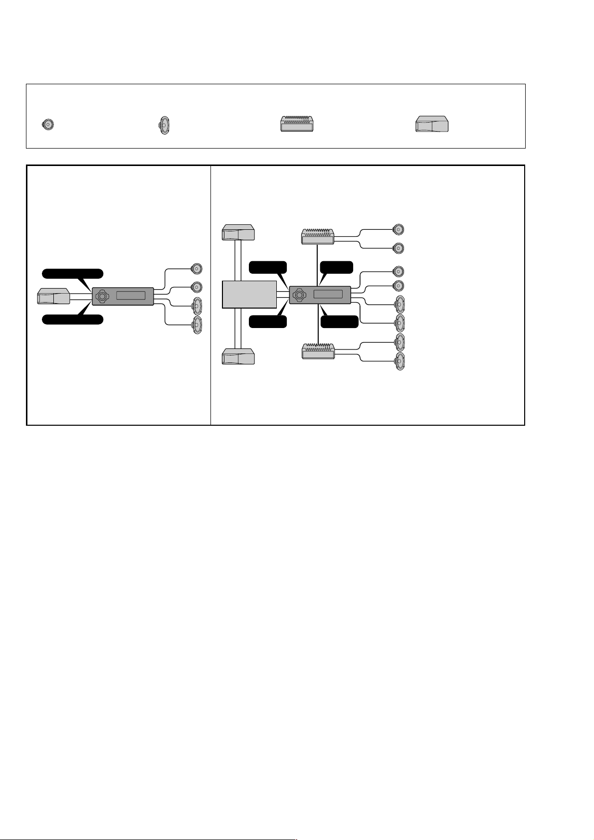
Connection diagram
Equipment used in illustrations
(not supplied)
Front speaker
Frontlautsprecher
Haut-parleur avant
Diffusori anteriori
Voorluidspreker
Anschlußdiagramm AansluitschemaSchema di collegamento
In Abbildungen dargestellte Geräte
(nicht mitgeliefert)
Rear speaker
Hecklautsprecher
Haut-parleur arrière
Diffusori posteriori
Achterluidspreker
Schéma de connexion
Appareils utilisés dans les
illustrations (non fournis)
Apparecchiatura utilizzata nelle
illustrazioni (non in dotazione)
Power amplifier
Endverstärker
Amplificateur de puissance
Amplificatore di potenza
Eindversterker
Apparatuur gebruikt voor
illustratiedoeleinden
(niet meegeleverd)
CD/MD changer
CD/MD-Wechsler
Changeur de CD/MD
Cambia CD/MD
CD/MD-wisselaar
AB
BUS AUDIO IN
BUS CONTROL IN
AUDIO IN
Source selector
Signalquellenwähler
Sélecteur de source
Selettore di fonte
Geluidsbronkiezer
CONTROL IN
BUS
BUS
AUDIO OUT
FRONT
AUDIO OUT
REAR
Notes
• For connecting two or more CD/MD changers,
the source selector XA-C30 (optional) is
necessary.
• Be sure to connect the ground cord before
connecting the amplifier.
• If you connect an optional power amplifier and
do not use the built-in amplifier, the beep sound
will be deactivated.
Hinweise
• Zum Anschließen von zwei oder mehr CD/MDWechslern wird der gesondert erhältliche
Signalquellenwähler XA-C30 benötigt.
• Schließen Sie unbedingt zuerst das Massekabel
an, bevor Sie den Verstärker anschließen.
• Wenn Sie einen gesondert erhältlichen
Endverstärker anschließen und den integrierten
Verstärker nicht benutzen, wird der Signalton
deaktiviert.
Remarques
• Dans le cas du raccordement de deux changeurs
de CD/MD ou plus, le sélecteur de source XA-C30
(optionnel) est indispensable.
• Raccordez d’abord le fil de masse avant de
connecter l’amplificateur.
• Si vous raccordez un amplificateur de puissance
optionnel et que vous n’utilisez pas
l’amplificateur intégré, le bip sonore est
désactivé.
Note
• Per collegare due o più cambia CD/MD, si deve
utilizzare il selettore di fonte XA-C30
(opzionale).
• Assicurarsi di collegare il cavo di terra, prima di
collegare l’apparecchio all’amplificatore.
• Se si collega un amplificatore di potenza in
dotazione e non si utilizza l’amplificatore
incorporato, il segnale acustico verrà disattivato.
Opmerkingen
• Om twee of meer CD/MD-wisselaars aan te
sluiten, hebt u de geluidsbronkiezer XA-C30
(optioneel) nodig.
• Sluit eerst de massakabel aan alvorens de
versterker aan te sluiten.
• Als u een los verkrijgbare vermogensversterker
aansluit en de ingebouwde versterker niet
gebruikt, is de pieptoon uitgeschakeld.
6
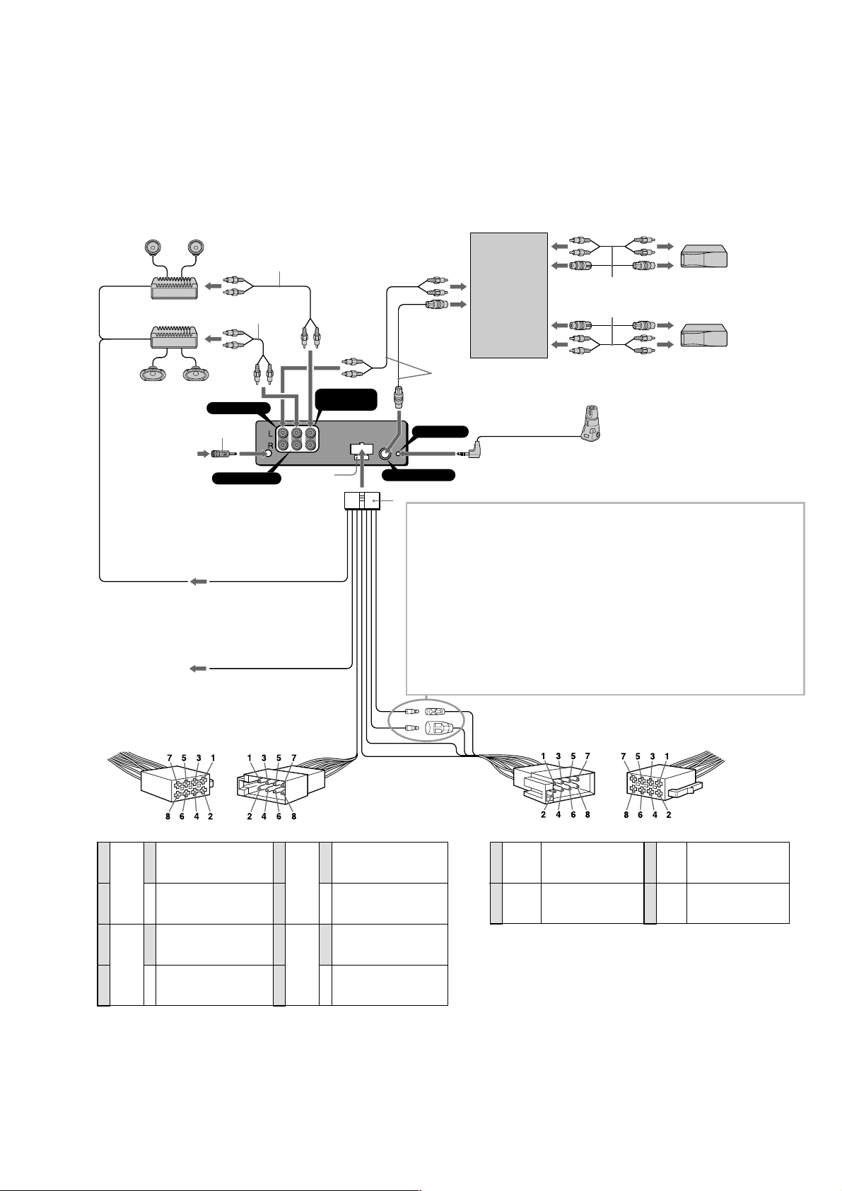
Connection example
*1Note for the aerial connecting
If your car aerial is an ISO (International
Organisation for Standardisation) type,
use the supplied adaptor 6 to connect it.
First connect the car aerial to the
supplied adaptor, then connect it to the
aerial jack of the master unit.
2
*
RCA pin cord (not supplied)
BUS AUDIO IN
from car aerial*
von Autoantenne*
de l’antenne de la voiture*
dall’antenna dell’auto*
van een auto-antenne*
to the interface cable of a car
telephone
an Schnittstellenkabel eines
Autotelefons
vers le cordon de liaison d’un
téléphone de voiture
al cavo interfaccia di un telefono
per auto
naar het interface-snoer van een
autotelefoon
to a car’s speaker connector
an Lautsprecheranschluß des Fahrzeugs
vers un connecteur de haut-parleur de la voiture
a un connettore del diffusore per auto
naar een luidsprekeraansluiting van de auto
1
1
6
1
1
1
AUDIO OUT REAR
AMP REM
Max. supply current 0.3 A
max. Versorgungsstrom 0,3 A
Courant max. fourni 0,3 A
Alimentazione massima fornita 0,3 A
Max. voedingsstroom 0,3 A
ATT
Anschlußbeispiel
*1Hinweis zum Anschließen der Antenne
Wenn Ihre Fahrzeugantenne der ISO-Norm
(ISO = International Organization for
Standardization - Internationale
Normungsgemeinschaft) entspricht,
schließen Sie sie mit Hilfe des
mitgelieferten Adapters 6 an.
Verbinden Sie zuerst die Fahrzeugantenne
mit dem mitgelieferten Adapter, und
verbinden Sie diesen dann mit der
Antennenbuchse des Hauptgeräts.
2
*
Cinchkabel (nicht mitgeliefert)
2
*
2
*
AUDIO OUT
FRONT
Fuse (10 A)
Sicherung (10 A)
Fusible (10 A)
Fusibile (10 A)
Zekering (10 A)
Blue/white striped
Blau-weiß gestreift
Rayé bleu/blanc
A strisce blu e bianche
Blauw/wit gestreept
Light blue
Hellblau
Bleu ciel
Azzurro
Hemelsblauw
Exemple de raccordement
*1Remarque sur le raccordement de
l’antenne
Si votre antenne de voiture est de type
ISO (organisation internationale de
normalisation), utilisez l’adaptateur
fourni 6 pour la raccorder.
Raccordez d’abord l’antenne de voiture à
l’adaptateur fourni et, ensuite, à la prise
d’antenne de l’appareil principal.
2
*
Cordon à broche RCA (non fourni)
Source selector
(not supplied)
Signalquellenwähler
(nicht mitgeliefert)
Sélecteur de source
(non fourni)
Selettore di fonte
(non in dotazione)
Geluidsbronkiezer
(niet bijgeleverd)
Supplied with XA-C30
Mit dem XA-C30 geliefert
Fourni avec le XA-C30
In dotazione con il modello XA-C30
Geleverd met de XA-C30
Esempi di collegamento
*1Nota per il collegamento dell’antenna
Se la vostra antenna della macchina è di
tipo ISO (International Organization
Standardization), utilizzare l’adattatore
6 in dotazione per collegarla.
Collegare prima l’antenna della macchina
all’adattatore in dotazione, quindi
collegarla alla presa dell’antenna
dell’apparecchio principale.
2
*
Cavo a piedini RCA (non in dotazione)
XA-C30
REMOTE IN
Insert with the cord upwards.
Mit dem Kabel nach oben einsetzen!
BUS CONTROL IN
Insérez avec le câble vers le haut.
Inserire con il cavo rivolto verso l’alto
Inbrengen met het snoer naar boven
8
WARNING
Auxiliary power connectors may vary depending on the car. Be
sure to check the power connection diagram. Improper
connections may damage your car. If the supplied power
connecting cord can not be used with your car, consult your
nearest Sony dealer.
VORSICHT
Die Hilfsstromanschlüsse können je nach Fahrzeugtyp
unterschiedlich sein. Sehen Sie im Stromanschlußdiagramm für
Ihr Fahrzeug nach, wie die Verbindungen ordnungsgemäß
vorgenommen werden müssen.
Fehlerhafte Verbindungen können zu Schäden an Ihrem
Fahrzeug führen. Wenn das mitgelieferte
Stromversorgungskabel nicht für den Einsatz in Ihrem Fahrzeug
geeignet ist, wenden Sie sich bitte an lhren Sony-Händler.
AVERTISSEMENT
Les connecteurs d’alimentation auxiliaire peuvent varier suivant
le type de voiture. Vérifiez le schéma de connexion
d’alimentation fourni avec l’appareil.
Un raccordement incorrect risque d’occasionner des dommages
à votre voiture. Si le cordon d’alimentation fourni ne peut être
utilisé avec votre voiture, consultez votre revendeur Sony.
Supplied with the CD/MD changer
Mit dem CD/MD-Wechsler geliefert
Fourni avec le changeur de CD/MD
In dotazione con il cambia CD/MD
Geleverd met de CD/MD-wisselaar
Rotary commander RM-X4S (not supplied)
Joystick RM-X4S (nicht mitgeliefert)
Satellite de commande RM-X4S (non fourni)
Telecomando a rotazione RM-X4S (non in dotazione)
Bedieningssatelliet RM-X4S (niet bijgeleverd)
ATTENZIONE
Il connettore di alimentazione ausiliaria può variare a seconda
del tipo di macchina. Controllare lo schema di collegamento
dell’alimentazione, collegamenti non corretti potrebbero
danneggiare la macchina.
Se il cavo di collegamento dell’alimentazione in dotazione non
può essere utilizzato con l’auto, consultare il rivenditore Sony
più vicino.
OPGELET
De hulpvoedingsaansluitingen kunnen verschillen naargelang
van de wagen.
Controleer het voedingsaansluitschema dat bij dit toestel
wordt geleverd. Onjuiste aansluiting kan uw wagen schade
toebrengen.
Indien de meegeleverde stroomaansluitingskabel voor uw
wagen niet bruikbaar is, raadpleeg dan uw dichtstbijzijnde
Sony-dealer.
to a car’s auxiliary power connector
an Hilfsstromanschluß des Fahrzeugs
vers un connecteur d’alimentation auxiliaire de la voiture
a un connettore di alimentazione ausiliaria per auto
naar een hulpvoedingsaansluiting van de auto
Voorbeeldaansluitingen
*1Opmerking bij de antenne-aansluiting
Indien uw wagen is uitgerust met een
antenne van het type ISO (International
Organisation for Standardization), moet
u die aansluiten met behulp van de
meegeleverde adaptor 6.
Sluit eerst de auto-antenne aan op de
meegeleverde adaptor en vervolgens de
antennestekker op het hoofdtoestel.
2
*
Tulpstekkersnoer (niet bijgeleverd)
Speaker, Rear, Right
Lautsprecher hinten rechts
1
Purple
Violett
Mauve
Viola
Paars
2
3
Grey
Grau
Gris
Grigio
Grijs
4
Negative polarity positions 2, 4, 6, and 8 have striped cords.
An den negativ gepolten Positionen (2, 4, 6 und 8) befinden sich gestreifte Adern.
Les positions de polarité négative 2, 4, 6 et 8 sont dotées de cordons rayés.
Le posizioni a polarità negativa 2, 4, 6 e 8 hanno cavi rigati.
De negatieve posities 2, 4, 6 en 8 hebben gestreepte kabels.
haut-parleur, arrière, droit
+
Diffusore, posteriore, destro
Luidspreker, achter, rechts
Speaker, Rear, Right
Lautsprecher hinten rechts
haut-parleur, arrière, droit
–
Diffusore, posteriore, destro
Luidspreker, achter, rechts
Speaker, Front, Right
Lautsprecher vorne rechts
haut-parleur, avant, droit
+
Diffusore, anteriore, destro
Luidspreker, voor, rechts
Speaker, Front, Right
Lautsprecher vorne rechts
haut-parleur, avant, droit
–
Diffusore, anteriore, destro
Luidspreker, voor, rechts
5
6
7
8
White
Weiß
Blanc
Bianco
Wit
Green
Grün
Vert
Verde
Groen
+
–
+
–
Speaker, Front, Left
Lautsprecher vorne links
haut-parleur, avant, gauche
Diffusore, anteriore, sinistro
Luidspreker, voor, links
Speaker, Front, Left
Lautsprecher vorne links
haut-parleur, avant, gauche
Diffusore, anteriore, sinistro
Luidspreker, voor, links
Speaker, Rear, Left
Lautsprecher hinten links
haut-parleur, arrière, gauche
Diffusore, posteriore, sinistro
Luidspreker, achter, links
Speaker, Rear, Left
Lautsprecher hinten links
haut-parleur, arrière, gauche
Diffusore, posteriore, sinistro
Luidspreker, achter, links
Yellow
4
5
Positions 1, 2, 3 and 6 do not have pins.
An Position 1, 2, 3 und 6 befinden sich keine Stifte.
Les positions 1, 2, 3 et 6 ne comportent pas de broches.
Le posizioni 1, 2, 3 e 6 non hanno piedini.
De posities 1, 2, 3 en 6 hebben geen pins.
continuous power supply
Gelb
permanente Stromversorgung
Jaune
Giallo
Geel
Blue
Blau
Bleu
Blu
Blauw
alimentation continue
alimentazione continua
continu voeding
power aerial control
Motorantenne
antenne électrique
comando dell’antenna elettrica
elektrisch bediende antenne antenne
7
8
Red
geschaltete Stromversorgung
Rot
Rouge
alimentazione commutata
Rosso
Rood
Black
Schwarz
Noir
Nero
Zwart
switched power supply
alimentation commutée
geschakelde voeding
ground
Masse
masse
terra
aarding
7
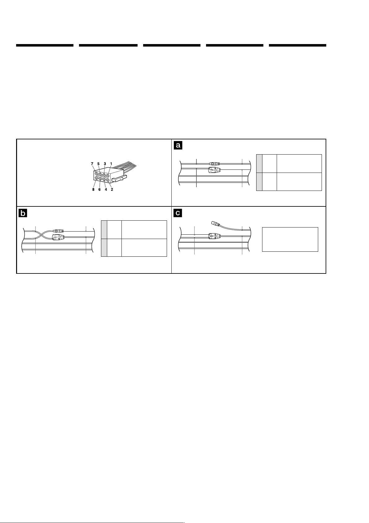
Power connection diagram
Auxiliary power connector may vary
depending on the car. Check your car’s
auxiliary power connector diagram to
make sure the connections match correctly.
There are three basic types (illustrated
below). You may need to switch the
positions of the red and yellow leads in the
car stereo’s power connecting cord.
After matching the connections and
switched power supply leads correctly,
connect the unit to the car’s power supply.
If you have any questions and problems
connecting your unit that are not covered
in this manual, please consult the car
dealer.
Stromanschlußdiagramm
Der Hilfsstromanschluß kann je nach
Fahrzeugtyp unterschiedlich sein. Sehen Sie
im Hilfsstromanschlußdiagramm für Ihr
Fahrzeug nach, wie die Verbindung
ordnungsgemäß vorgenommen werden
muß. Es gibt, wie unten abgebildet, drei
grundlegende Typen.
Sie müssen möglicherweise die rote und
gelbe Leitung des Stromversorgungskabels
der Autostereoanlage vertauschen.
Stellen Sie die Anschlüsse her, schließen Sie
die geschalteten
Stromversorgungsleitungen richtig an, und
verbinden Sie dann das Gerät mit der
Stromversorgung Ihres Fahrzeugs. Wenn
beim Anschließen des Geräts Fragen oder
Probleme auftreten, die in dieser
Bedienungsanleitung nicht erläutert
werden, wenden Sie sich bitte an den
Autohändler.
Schéma de connexion
d’alimentation
Le connecteur d’alimentation auxiliaire
peut varier suivant le type de voiture.
Vérifiez le schéma du connecteur
d’alimentation auxiliaire de votre voiture
pour vous assurer que les connexions
correspondent. Il en existe trois types de
base (illustrés ci-dessous). Il se peut que
vous deviez commuter la position du fil
rouge et jaune du cordon d’alimentation de
l’autoradio.
Après avoir établi les connexions et
commuté correctement les fils
d’alimentation, raccordez l’appareil à
l’alimentation de la voiture. Si vous avez
des questions ou des difficultés à propos
de cet appareil qui ne sont pas abordées
dans le présent mode d’emploi, consultez
votre revendeur automobile.
Diagramma dei
collegamenti di
alimentazione
Il connettore di alimentazione ausiliaria
può variare a seconda della macchina.
Controllare il diagramma del connettore di
alimentazione ausiliaria della macchina per
essere sicuri che le connessioni
corrispondano correttamente. Vi sono tre
tipi di base (illustrazione sotto). Potrà
essere necessario cambiare le posizioni dei
conduttori rosso e giallo nel cavo di
alimentazione dello stereo della macchina.
Dopo aver fatto corrispondere le
connessioni e i cavi di alimentazione
commutata, collegare l’apparecchio
all’alimentazione della macchina. Se si
hanno domande o se sorgono problemi che
non sono stati trattati nel manuale nel
collegare l’apparecchio, contattare
l’autoconcessionario.
Voedingsaansluitschema
De hulpvoedingsaansluiting kan
verschillen naargelang van de wagen.
Controleer het voedingsaansluitschema dat
bij dit toestel wordt geleverd om te zien of
de aansluitingen kloppen. Er zijn drie
basistypes (zie illustratie hieronder).
Het is mogelijk dat u de positie van de
rode en gele draden in de voedingskabel
van de autoradio moet omwisselen.
Als de aansluitingen en geschakelde
voedingskabels kloppen, sluit u het toestel
aan op de voeding van de wagen. Indien u
nog vragen of problemen hebt in verband
met het aansluiten van het toestel die niet
in deze handleiding vermeld staan,
raadpleeg dan de autodealer.
Auxiliary power connector
Hilfsstromanschluß
Connecteur d’alimentation auxiliaire
Connettore di alimentazione ausiliare
Hulpvoedingsaansluiting
Red
Rot
Rouge
Rosso
Rood
Yellow
Gelb
Jaune
Giallo
Geel
Red
Rot
Rouge
Rosso
Rood
Yellow
Gelb
Jaune
Giallo
Geel
Red
Rot
Rouge
Rosso
Rood
Yellow
Gelb
Jaune
Giallo
Geel
Red
Rot
Rouge
Yellow
4
7
switched power supply
geschaltete Stromversorgung
Gelb
alimentation commutée
Jaune
alimentazione commutata
Giallo
Geel
Rouge
Rosso
Rood
geschakelde voeding
continuous power supply
Red
permanente Stromversorgung
Rot
alimentation continue
alimentazione continua
continu voeding
Rosso
Rood
Yellow
Gelb
Jaune
Giallo
Geel
Red
Rot
Rouge
Rosso
Rood
Yellow
Gelb
Jaune
Giallo
Geel
Red
Rot
Rouge
Rosso
Rood
Yellow
Gelb
Jaune
Giallo
Geel
continuous power supply
Yellow
permanente Stromversorgung
Gelb
Jaune
4
Giallo
Rouge
7
Rosso
Rood
the car without ACC position
Fahrzeug ohne Zubehörposition (ACC)
Voiture sans position ACC
la macchina senza posizione ACC
Wagen zonder ACC stand
alimentation continue
alimentazione continua
Geel
switched power supply
Red
geschaltete Stromversorgung
Rot
alimentation commutée
alimentazione commutata
geschakelde voeding
continu voeding
8
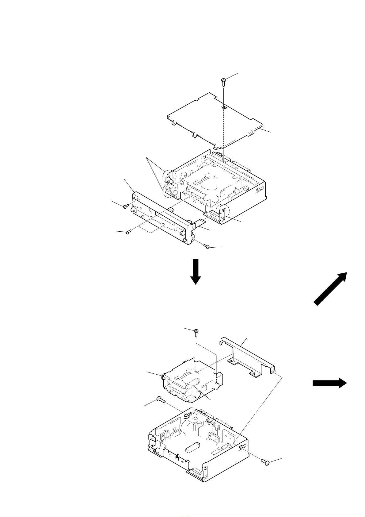
SECTION 2
)
DISASSEMBLY
Note: Follow the disassembly procedure in the numerical order given.
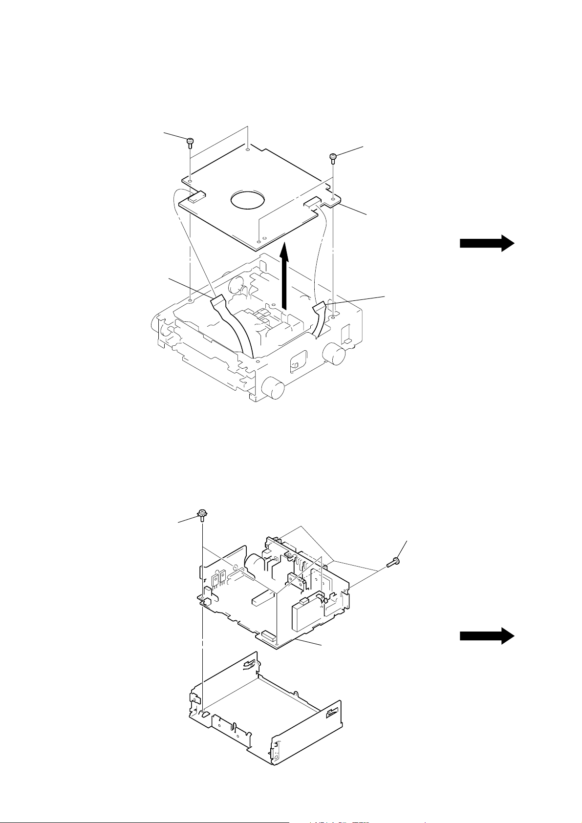
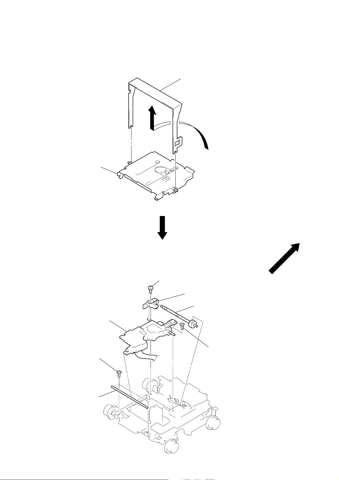
SUB PANEL ASSY
4
two claws
5
sub panel assy
3
screw
(PTT2.6
×
8)
1
screw
(PTT2.6
×
5)
2
cover
3
two screws
(PTT2.6
×
8)
MECHANISM DECK (MG-164NA-138)
5
mechanism deck
(MG-164NA-138)
3
two screws
(PTT2.6
4
claw
6
flexible flat cable (14 core) (CN500
3
screw
(PTT2.6
×
5)
×
8)
4
bracket (MD)
1
screw
(PTT2.6
2
×
5)
connector
(CN101)
1
screw
(PTT2.6
×
5)
9
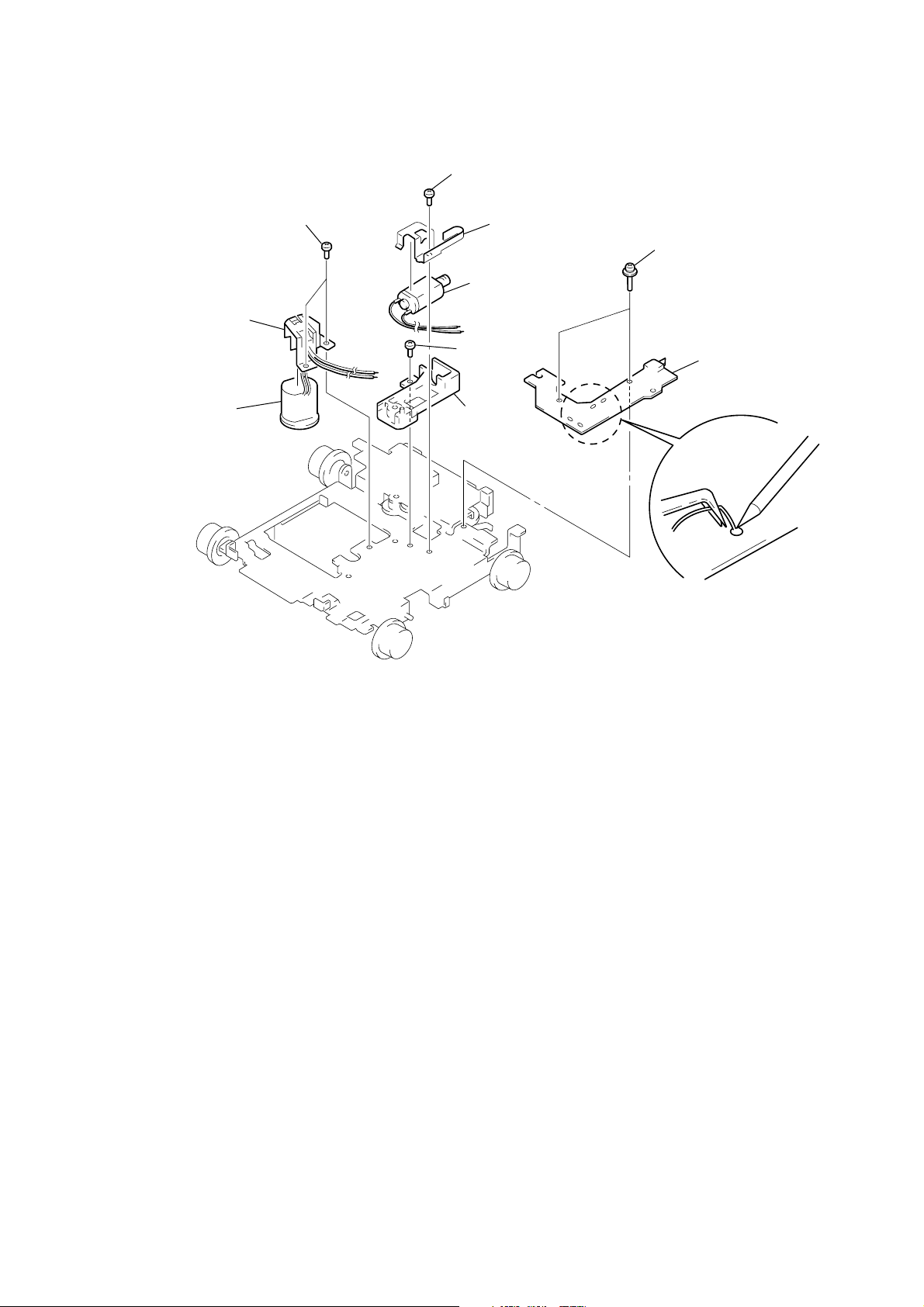
SERVO BOARD
d
1 sensor flexible board
2 two screws
(BVTT2 × 4)
2 two screws
(BVTT2 × 4)
3 servo board
(CN102)
1 flexible boar
(CN103)
MAIN BOARD
1
three ground point
screws (PTT2.6 × 6)
3
main board
2
three screws
(PTT2.6 × 8)
10
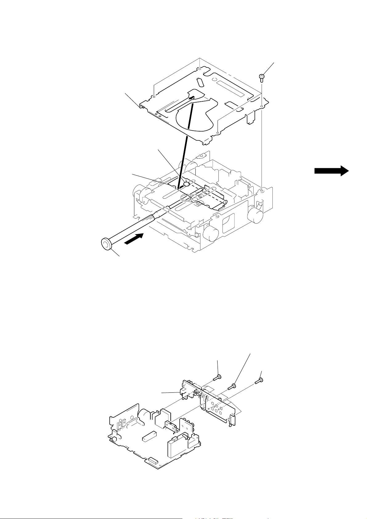
MD COVER ASSY
)
3
MD cover assy
shaft (MD cover guide)
cassette holder
1
four screws
(BVTT2
×
4
HEAT SINK
A
2
Pushing the Cassette Holder in the direction of the arrow A with a
screwdriver, etc., disengage the Shaft (MD Cover Guide) from
the slot in the MD Cover Assy.
Note: Take care not to scratch the optiocal Pick-up when pushing
the Cassette Holder with a screwdriver. etc.
2
two screws
(PTT2.6 × 12)
1
3
heat sink
1
three screws
(PTT2.6
×
8)
three screws
(PTT2.6
×
8)
11
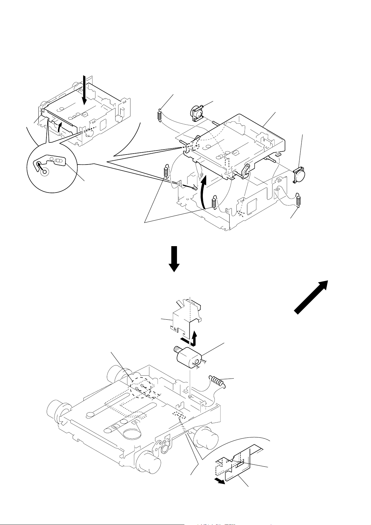
FLOAT BLOCK
y
float block
A
lever (lock R)
lever (lock L)
3
Pushing an arrow A part, raise the float block
up ward at the front to release a lock.
1
tension spring (FLOAT B)
2
two tension springs (FLOAT F)
5
two damper assy
4
6
float block
5
two damper ass’
1
tension spring (FLOAT B)
LO MOTOR ASSY (LOADING) (M903)
4 Remove the bracket (LO)
in the direction of the arrow A.
1 Remove solders of motor (M903)
A
5 LO motor assy (loading)
(M903)
2 tension spring (rack)
3 claw
12
bracket (LO)
– bottom view –
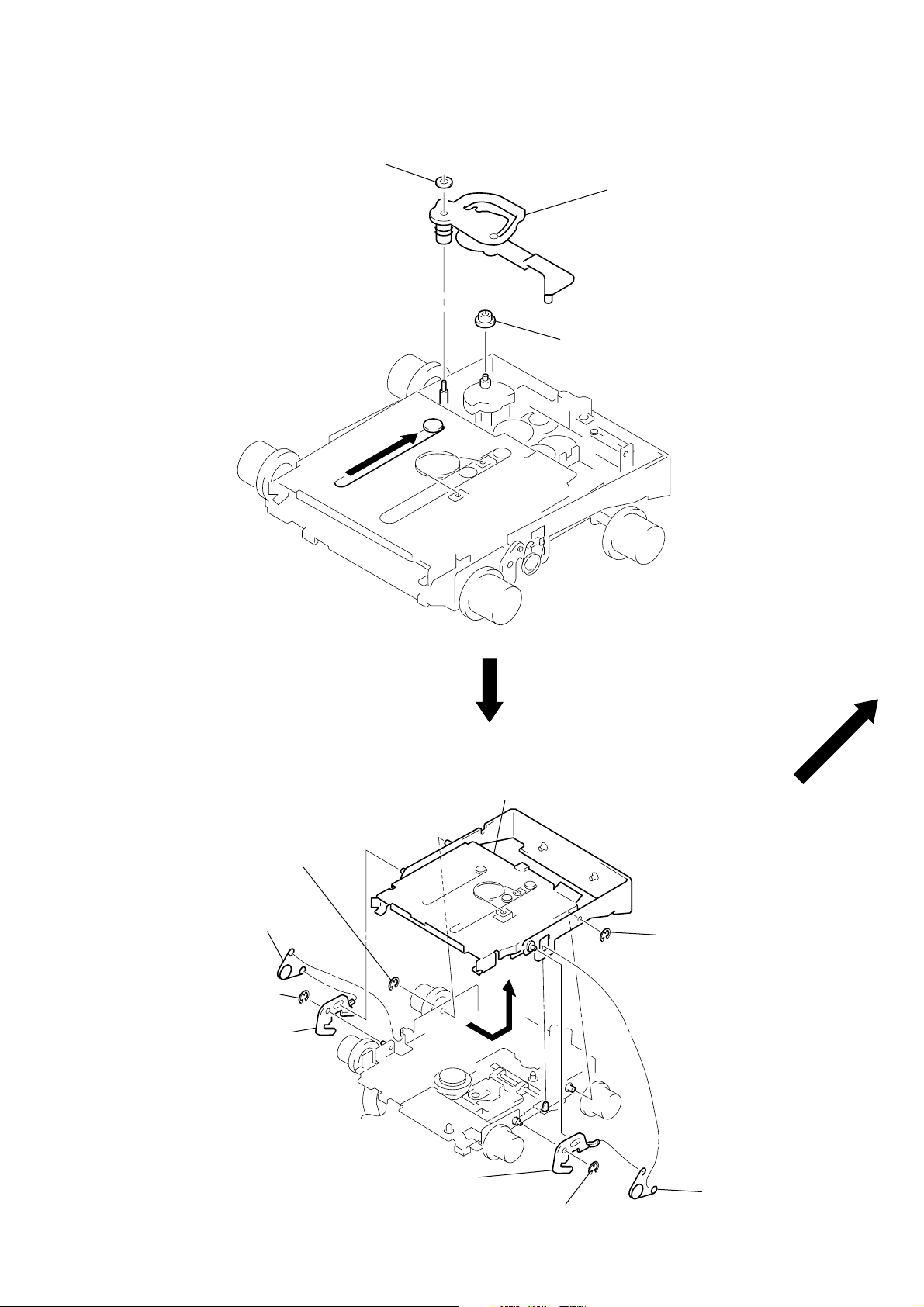
LEVER (LE23) ASSY
y
2
stopper washer
1
2
3
roller (gear E)
lever (LE23) ass
HOLDER ASSY
2 type-E stop ring 1.5
3 lever (lock R)
2 type-E stop ring 1.5
1 spring (CHKG)
4 Remove the holder assy in the
direction of the arrow.
2 type-E stop ring 1.5
3 lever (lock L)
1 spring (CHKG)
2 type-E stop ring 1.5
13
CHUCKING ARM ASSY
y
holder assy
1 Remove the chucking arm ass
in the direction of the arrow.
OPTICAL PICK-UP (KMS-241C)
7
optical pick-up
(KMS-241C)
1
two screws
(K2
×
3)
2
guide shaft (OPT L)
4
screw
(B2
×
3)
6
bearing (SL)
5
feed screw assy
3
screw
(K2
×
3)
14
SL MOTOR ASSY (SLED) (M902), SP MOTOR ASSY (SPINDLE) (M901)
4 screw
(P1.7 × 1.8)
5 bracket (SL)
9 two screws
(P1.7 × 1.8)
0 bracket (SP)
qa SP motor assy
(spindle) (M901)
7 screw
(B2 × 3)
2 two screws
(2 × 8)
3 sensor board (B)
1 Remove solders of motors
(M901, M902)
8 base (SL)
6 SL motor assy
(sled) (M902)
15

SECTION 3
ELECTRICAL ADJUSTMENTS
TEST MODE
This set have the test mode function.
<Set the Test Mode>
1. Turn ON the regulated po wer supply. (The clock is displayed)
Note: Press the [OFF] button, if the clock is not displayed.
2. Push the preset [4] button.
3. Push the preset [5] button.
4. Press the preset [1] button for more than two seconds.
5. Then the display indicates all lights, the test mode is set.
<Release the Test mode>
1. Push the [OFF] button.
MD SECTION
MD section adjustments are done automatically in this set.
TUNER SECTION
Tuner section adjustments are done automatically in this set.
16
SECTION 4
DIAGRAMS
MDX-CA580
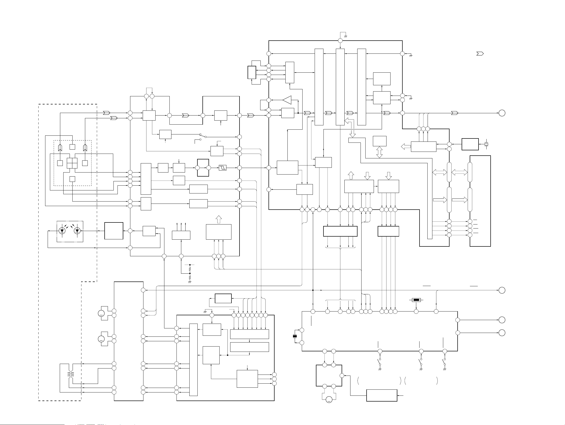
4-1. BLOCK DIAGRAM – SERVO Section –
IC303
I
1
J
2
A
4
B
5
C
6
D
7
E
8
F
9
APC
11
PD
10
IN4R
IN4F
IN2F
IN2R
IN1F
IN1R
IN3F
IN3R
I
J
F
C B
I J
D A
E
DETECTOR
LASER DIODE
OPTICAL PICK-UP BLOCK
(KMS-241C)
2-AXIS
DEVICE
(FOCUS)
(TRACKING)
05
LDPD
B
A
C
D
E
F
ILCC
PD
M901
(SPINDLE)
M902
(SLED)
FCS+
FCS–
TRK+
TRK–
AUTOMATIC
POWER
CONTROL
Q302
FOCUS/TRACKING COIL DRIVE,
SPINDLE/SLED MOTOR DRIVE
6
27
25
21
23
12
10
8
OUT4F
OUT4R
OUT2F
OUT2R
OUT1F
OUT1R
OUT3F
OUT3R
M
M
48 47
RF AMP
I-V
AMP
I-V
AMP
16PSB
3
4
29
30
19
18
14
15
MORFO
LD/PD
AMP
SPFD
SPRD
MORFI
RFO
B.P.F.
AT
AMP
APCREF
12
3T
46
WBL
B.P.F.
ABCD
AMP
WBL3TEQ
V-I
CONVERTER
F0CNT
20
APCREF
83
SFDR
92
SRDR
91
FFDR
88
FRDR
89
TFDR
86
TRDR
85
FOCUS/TRACKING ERROR AMP
AGCI
40
TEMP
ADFM
29 30
FOCUS
ERROR AMP
TRACKING
ERROR AMP
+3.3V
AUTOMATIC
CONTROL
DIGITAL
SIGNAL
PROCESS
PWM GENERATOR
RF AMP,
IC302
RF AGC
& EQ
EQ
WBL
PEAK &
BOTTOM
ADIN
COMMAND
SERIAL/
PARALLEL
CONVERTER,
DECODER
XLAT
SCLK
SWDT
1716 18
PEAK HOLD
Q301
+3.3V
13
RECP
POWER
SERVO
DIGITAL SERVO
SIGNAL PROCESSOR
IC301 (2/2)
RF
AUX
PEAK
BOTM
ADFG
ABCD
FE
TE
SE
ABCD
AUX1
38
33
37
36
32
35
34
26
28
7465647566 63
FE
TE
AUX2
ABCD
ANALOG MUX
A/D CONVERTER
FROM CPU
INTERFACE
AUTO
SEQUENCER
FILTER
73 62
SE
PEAK
XLRF
CKRF
DTRF
100
59
58
61
60
51
52
55
78
79
BOTM
EFMO
FILI
PCO
CLTV
FILO
ASYO
ASYI
COMPA-
RFI
RATOR
ADIP
ADFG
DEMODULATOR/
DECODER
F0CNT
X501
10MHz
80
81
82
PLL
15
TX
EFM/ACIRC
ENCODER/DECODER
SUBCODE
PROCESSOR
SPINDLE
SERVO
SPFD
SPRD
DQSY11SQSY14XINT
XRST
94 93
10
12
59 62 55 54 52 45 51 64 26 27 28 29
MD-RST
31
EXTAL
XTAL
32
7 6
5 4
LOADING
MOTOR DRIVE
IC305
(LOADING)
RIN FIN
OUT1 OUT2
1 7
M903
SHOCK PROOF
MEMORY CONTROLLER
13 11 15 17
LEVEL SHIFT
IC502 (1/2)
7923
SQSY
CC-XINT
EJECT
LOAD
6VREF
M
ATRAC
CPU
INTERFACE
SENS
SRDT
SWDT
9 8 5 6 7
SWDT
SENS
MD-SI
MD-SO
MD MECHANISM CONTROLLER
ON: When the disc loading start
IC301 (1/2)
ADDT
SAMPLING
RATE
CONVERTER
DIGITAL
AUDIO
ENCODER/DECODER
INTERFACE
D-RAM
INTERNAL BUS
SCLK
XLAT
2468
18 16 14 12
SCLK
XLAT
MD-LAT
MD-CKO
IC501 (1/2)
63
and the disc eject completion
REFERENCE VOLTAGE
REGULATOR
Q303
DOUT
DADT
MONITOR
CONTROL
MNT0
MNT1
MNT2
1 2 3 4
LEVEL SHIFT
IC502 (2/2)
FOK
SHOCK
XBUSY
MNT0
MNT1
MNT2
C-SW
DIN
MNT3
SLOCK
23
DIGITAL SIGNAL PROCESSOR,
EFM/ACIRC ENCODER/DECODER,
SHOCK PROOF MEMORY CONTROLLER,
ATRAC ENCODER/DECODER, 2M BIT D-RAM
21
22
24
MNT3
ON: When completion of
LO +12V
IC301 (1/2)
BCK
LRCK
2526 27
LRCK
XBCK
CLOCK
GENERATOR
RESET
TH501
39
TEMP
E-SW
11 56
the disc loading
FS256
FS256
XRAS
XCAS
EMPHASIS
66
DEEMP
OSCI
OSCO
D0 – D3A00 – A09
XOE
XWE
LOCK
A-MUTE
LIMIT-IN
(LIMIT)(CHUCKING DETECT)(LOADING DETECT)
DADT, BCK, LRCK, FS256
16
17
41 22
45 3
44 4
42 23
512FS OSC
IC304
47, 46, 48, 49
32 – 29, 34 – 38, 43
21
67
• SIGNAL PATH
: MD PLAY
D0 – D3
1, 2, 24, 25
A0 – A9
9 – 12, 14 – 18, 5
OE
WE
RAS
CAS
D-RAM
IC307
RESET, EMPHASIS
LOCK
MD-ATT
(Page 19)
A
X301
22.5792MHz
(Page 19)
B
C
(Page 19)
D
(Page 19)
1717
MDX-CA580
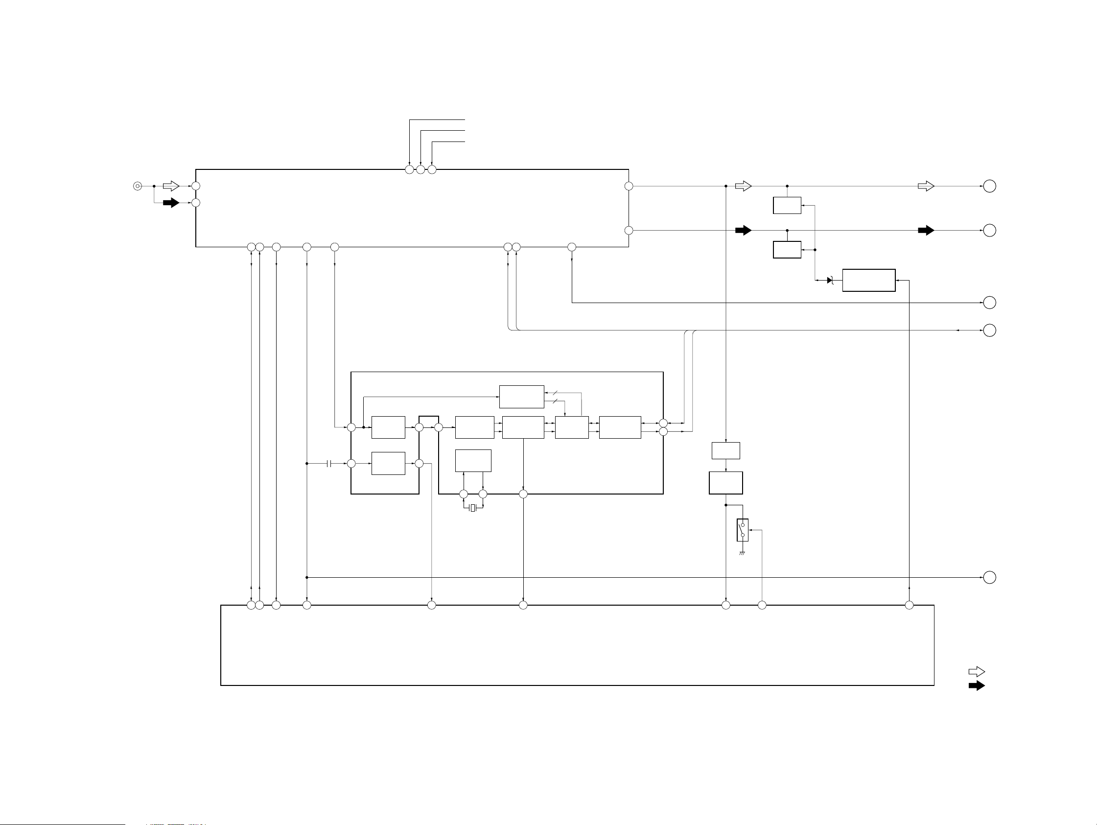
4-2. BLOCK DIAGRAM – TUNER Section –
FM/AM TUNER UNIT
2
1
ANT-FM
ANT-AM
TU1
SDA (E2PROM)
SCL (E2PROM)
17
18
FM-AGC
4
S-METER
14
J1
(FM/AM ANTENNA)
RDS-DET
9
11
5
VCC (8.5V)
VDD E2P (5V)
16
VDD (5V)
BU B+
TUNER +8.7V
TUNER +5.6V
SDA (12CBUS)
SCL (12CBUS)
12 13
19
IF-AM
MPX
AM-DET
10
MUTING
Q111
8
MUTING
Q121
MUTING
CONTROL SWITCH
D131
Q131
MPX
AM
IF-AM
E
F
G
(Page 19)
(Page 19)
(Page 19)
DATA
CLOCK
DATA
CLOCK
RDS DECODER
IC51
SC
57 kHz
16
BAND-PASS
MPX
LVIN
20
DETECTOR
9
10
51
53
FILTER
MULTI
PATH
OUT
MPTH
CIN
19
CLOCKED
COMPARATOR
OSCILLATOR
& CLOCK
OSCI
OSCO
4
5
X51
4.332MHz
18
2
52
SIGNAL
QUALITY
DECODER
RDS/RDBS
DEMODULATOR
& DECODER
DAVN
8
64
5
4
INTERFACE
REGISTER
IIC BUS
SLAVE
TRANSCEIVER
SDA
SCL
9
10
BUFFER
Q1
BAND-PASS
FILTER
IC90
Q90
NOISE DET
DISCHARGE
SWITCH
50
32
56
DATA, CLOCK
S-METER
I
H
(Page 19)
(Page 19)
E2P SIO
E2P CKO
FMAGC
VSM
MPTH
MASTER CONTROLLER
IC501 (1/3)
DAVN
QUALITY
NS MASK
TUNATT
• SIGNAL PATH
: FM
05
: MW/LW
1818
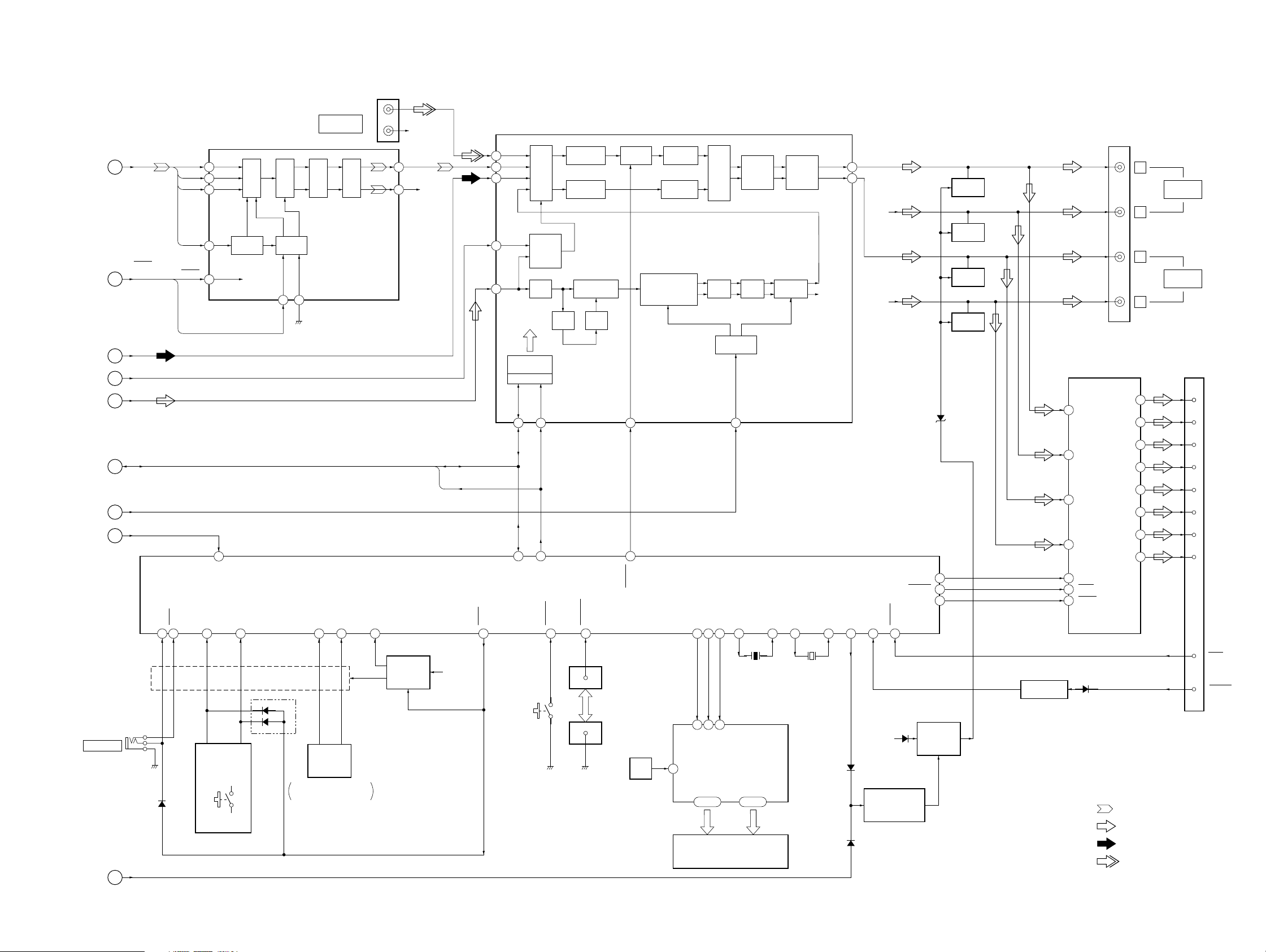
4-3. BLOCK DIAGRAM – MAIN Section –
MDX-CA580
(Page 17)
(Page 17)
(Page 18)
(Page 18)
(Page 18)
(Page 18)
(Page 18)
(Page 17)
CNJ151 (1/2)
DM0
NOISE
AUDIO IN
SHAPER
DADT,
BCK,
LRCK,
FS256
A
LRCK
FS256
RESET,
EMPHASIS
B
AM
F
IF-AM
G
MPX
E
DATA, CLOCK
I
S-METER
H
LOCK
C
RESET
EMPHASIS
DATADADT
5
BCKBCK
6
4
1
15
84
LRCK
XTI
RSTB
LOCKIN
INPUT
CLK
CONTROL
INTERFACE
CONTROL
FILTER
DIGITAL
MODE
DM1
17 16
(L)
BUS
(R)
VOUTL
D/A
VOUTR
COMVERTER
DIGITAL FILTER,
D/A CONVERTER
IC101
R-CH
12
9
R-CH
MASTER CONTROLLER
IC501 (2/3)
INPUT SELECT,
ELECTRICAL VOLUME, FM MPX
3
1
11
12
13
DATA
CLOCK
FD1L
SEL
AM
AMIF
MPX
IC151
BLANKER
L.P.F.
DIGITAL
CONTROL
IIC BUS
SDA
20
70 71
I2C SIO
INPUT
MULTIPLEXER
AM/FM
NOISE
SCL
21
I2C CKO
PLL
LOUDNESS/
VOLUME
PILOT
CANCELATION
PILOT
DET
SOFT
MUTE
DEMODULATOR
+STEREO ADJUST
+STEREO BLEND
SM
18
57
VOLATT
TONE
CONTROL
LOUDNESSMUTE
MONO
FADER
OUTPUT
SELECTOR
L.P.F. S & H HIGH-CUT
D/A
CONVERTER
LEVEL
14
MIXER
OUTLF
OUTLR
R-CH
CNJ151 (2/2)
30
29
R-CH
R-CH
D621
BEEP
AMPATT
AMPON
MUTING
Q171
MUTING
Q271
MUTING
Q181
MUTING
Q281
POWER AMP
IC611
12
FL-IN
14
FR-IN
RL-IN
11
15
RR-IN
16
60
59
16
AUX IN
MUTE
22
4
STNBY
FL+
FL–
FR+
FR–
RL+
RL–
RR+
RR–
L
AUDIO OUT
FRONT
R
L
AUDIO OUT
REAR
R
CN601 (1/2)
(POWER)
5
3
21
23
9
7
17
19
1
9
4
12
2
10
3
11
FRONT L (+)
FRONT L (–)
FRONT R (+)
FRONT R (–)
REAR L (+)
REAR L (–)
REAR R (+)
REAR R (–)
REMOTE IN
(Page 17)
05
J501
RCIN1
RCIN0
48 46 47 36 37 76 6785 587473929315141335 79 81
D653
KEYIN0
LSW810,
LSW901 – 917,
S901 – 904
KEYIN1
D501
VOLUME/BASS/TREBLE/
BALANCE/FADER CONTROL
REIN0
ROTARY
ENCODER
RE901
REIN1
KEYACK
KEY ACTIVE
SWITCH
Q651, 652
U-COM +5V
AD-ON
SW504
(NOSE DETECT)
NOSESW
DOORSW
12
14
1
CN500
MAIN UNIT SIDE
CN901
FRONT PANEL SIDE
OSC
C953, R957
LCDSO
LCDCKO
LCDCE
X1
X0
X1A
X501
3.68MHz
6263
64
DI
CL
SE
LIQUID CRYSTAL
OSC
DISPLAY DRIVER
–
S51 COM1
S04
–
4
51
IC901
–
COM4
–
52
55
60
32.768kHz
X502
X0A
D502
ATT
TELATT
BACK-UP B+
CONTROL SWITCH
TEST IN
MUTING
Q622
D622
BATTERY OFF
MUTE DRIVER
Q621
LEVEL SHIFT
Q571
15
13
D571
• R-ch is omitted due to same as L-ch.
• SIGNAL PATH
: MD PLAY
TEST
TEL-ATT
: FM
LCD901
LIQUID CRYSTAL DISPLAY
MD-ATT
D
D302
: MW/LW
: BUS AUDIO IN
1919
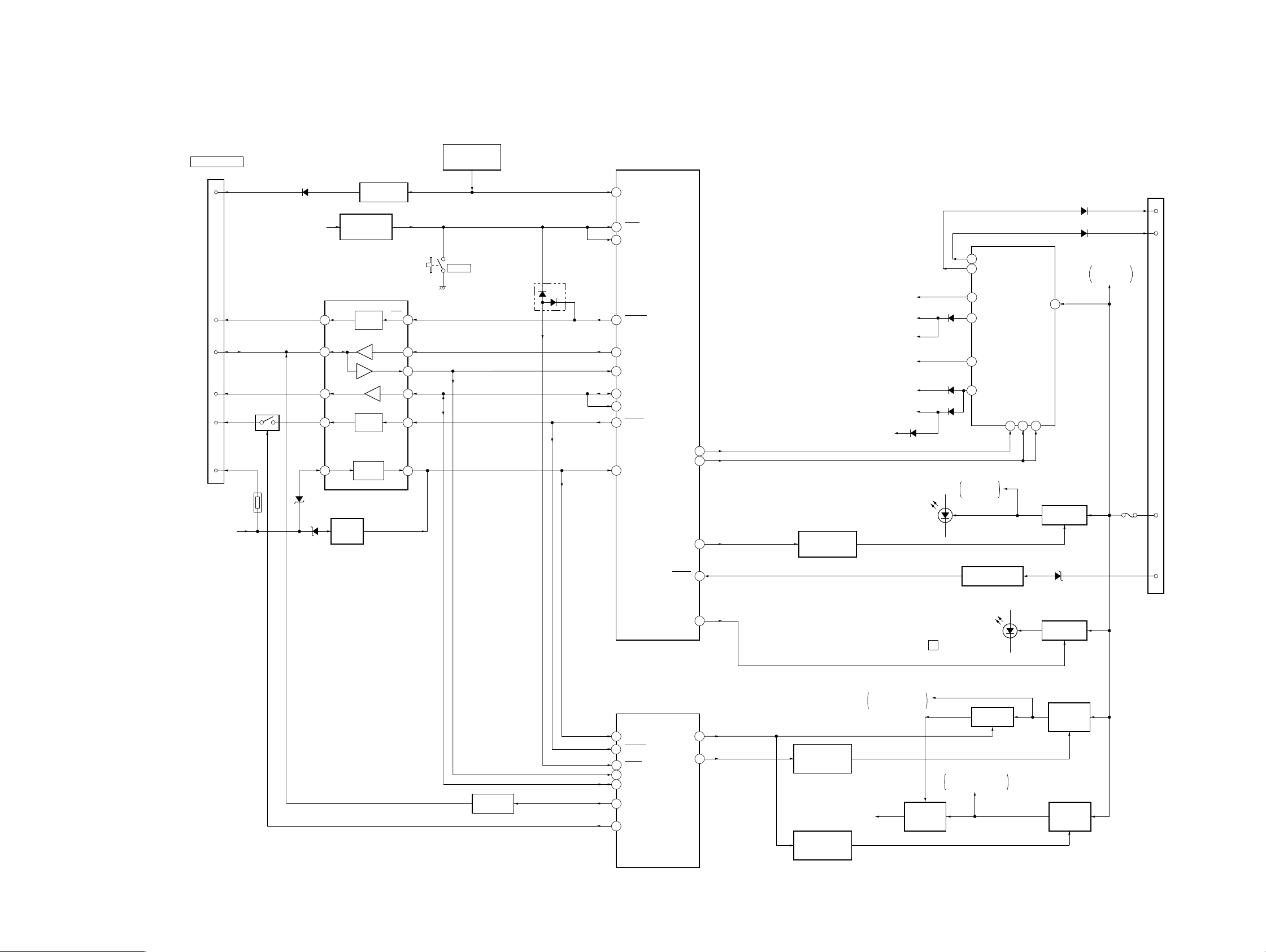
MDX-CA580
4-4. BLOCK DIAGRAM – BUS CONTROL/POWER SUPPLY Section –
CN701
BUS CONTROL IN
(FOR SONY BUS)
SIRCS
RESET
DATA
CLK
BUS ON
BATT
BACK-UP B+
3
2
5
4
6
7
BUS ON SWITCH
Q705
TH701
D708
BU B+
2
6
4
1
3
D702
D701
SIRCS BUFFER
Q704
RESET SIGNAL
GENERATOR
IC652
SONY BUS INTERFACE
IC701
RST
RESET
SWITCH
DATA
CLK
BUS ON
OUT
BATT
BATTERY
DETECT
Q701
BUS ON
SWITCH
BATTERY
SWITCH
DATA IN
DATA OUT
CLK IN
RST
BUS
ON IN
BU IN
REMOTE CONTROL
RECEIVER
IC951
SW503
RESET
13
9
8
11
12
10
D301
MASTER CONTROLLER
IC501 (3/3)
24
SIRCS
RSTX
90
86
HSTX
11
SYSRST
UNISO
18
17
UNISI
19
UNICKO
20
UNICKI
3
BUSON
BUIN
77
PW ON
TUNON
ILLON
ACC IN
CN601 (2/2)
FU601
(POWER)
6
5
16
7
ANT-R
AMP-R
+B
ACC
D673
D674
6
AMP+B
8
ANT+B
REGULATOR
TUNER +8.7V
TUNER +5.6V
RDS DECODER
(IC51) B+
COM +8V
(AUDIO CIRCUIT B+)
BU B+
PULL UP +5V
U-COM +5V
120
1
7
82
REGULATOR
CONTROL SWITCH
Q633
D677
LED901 – 904,
LED910 – 913,
LSW901 – 917
D2
D1
D676
LCD DRIVER
(IC901) B+
ACCESSORY CHECK
11
10
9
5
LCD B+
TU8.7V
TU5.6V
COM8V
BU+B
Q661
IC671
STB
4
VCC
8.7VON SW
5.6VON SW
23
REGULATOR
7
Q631
D662
BACK-UP B+
POWER AMP
(IC611) B+
29
DOORIND
LO +12V
MD MECHANISM CONTROLLER
IC501 (2/2)
MDMON
65MD-ON
REGULATOR
10
CONTROL SWITCH
Q363
REGULATOR
CONTROL SWITCH
Q250
60
BU-IN
BUS-ON
61
30
RESET
UNISI
49
48
UNICKIO
LEVEL SHIFT
Q706
05
50
46
UNISO
LINKOFF
LOADING MOTOR
DRIVER (IC305) B+
+3.3V
LED810
(MD DISC SLOT)
LSW810
Z
VCC
+3.3V
REGULATOR
IC401, Q401
LED810,
LSW810
B+ SWITCH
Q402, 403
DRIVER +5V
MOTOR/COIL DRIVER
(IC303) B+
REGULATOR
Q551
+12V
REGULATOR
Q361
+5V
REGULATOR
Q362
2020
 Loading...