

Sony MDXC-7900-R Service manual
MDX-C7900/C7900R
SERVICE MANUAL
Ver 1.1 2001.08
Refer to RM-X4S Service Manual (9-925-
[][]
698-
) issued previously for information
of remote commander (RM-X4S) supplied
with this set.
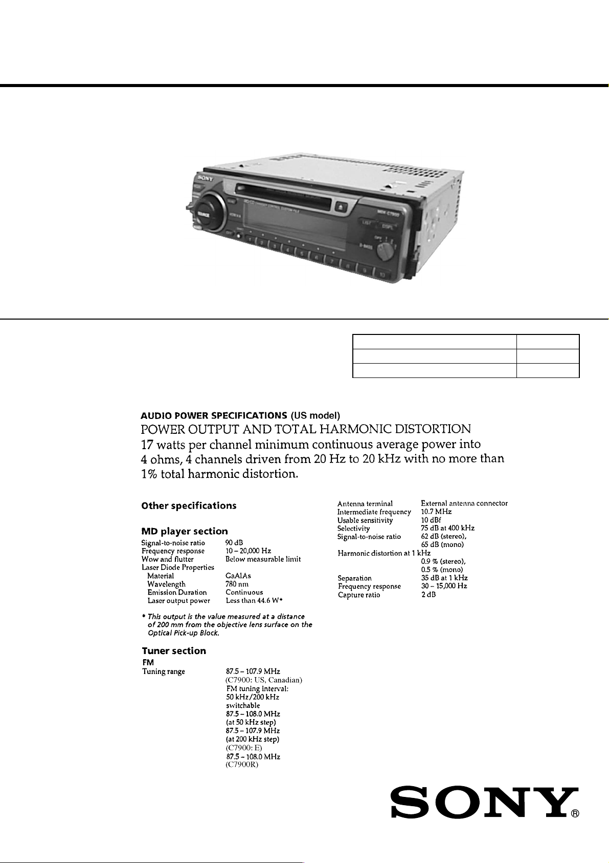
Photo: MDX-C7900
SPECIFICATIONS
US Model
Canadian Model
E Model
MDX-C7900
AEP Model
UK Model
MDX-C7900R
Model Name Using Similar Mechanism NEW
Base Mechanism Type MG-164KT-138
Optical Pick-Up Name KMS-241A/J2N
9-925-787-12 Sony Corporation
2001H0500-1 e Vehicle Company
C 2001.8 Shinagawa Tec Service Manual Production Group
– Continued on next page –
MDX-C7900
FM/AM MINIDISC PLAYER
MDX-C7900R
FM/MW/LW MINIDISC PLAYER
Ver 1.1
TABLE OF CONTENTS
1. SERVICE NOTE ....................................................... 3
2. GENERAL
Location of Controls (MDX-C7900).............................. 4
Location of Controls (MDX-C7900R) ........................... 5
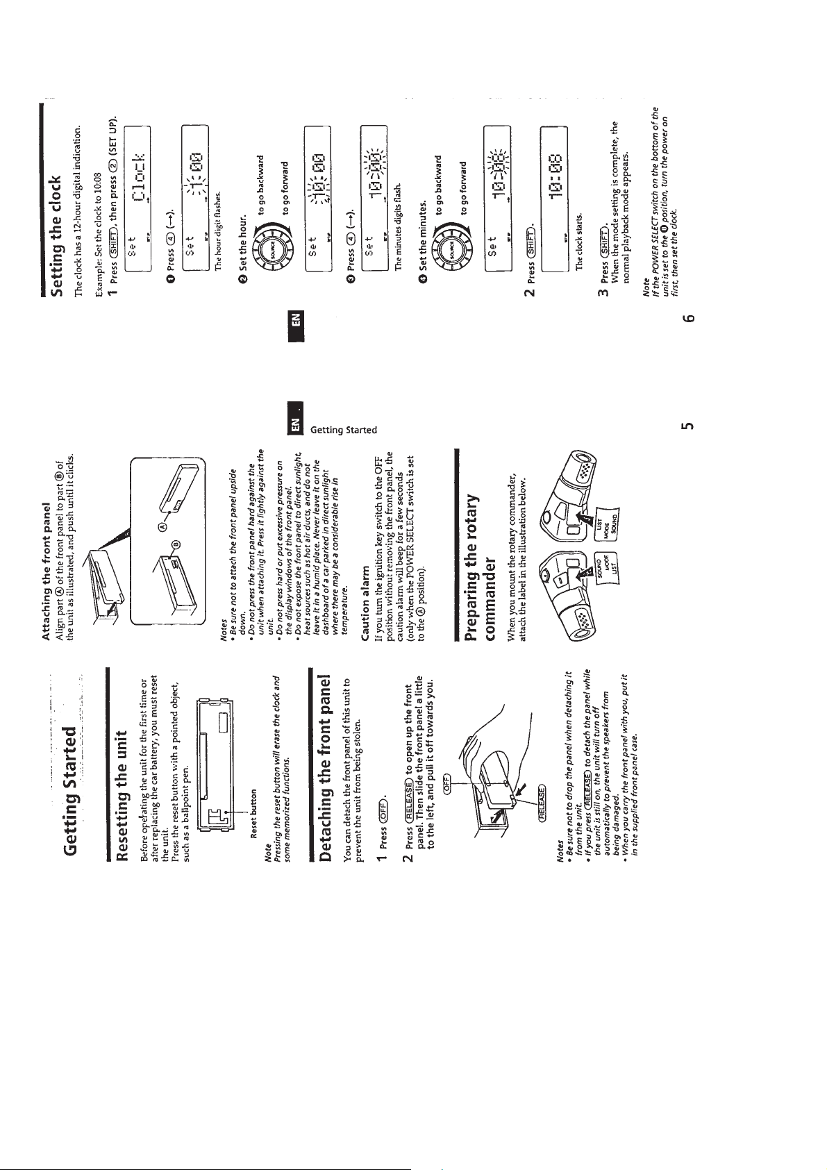
Resetting the Unit ........................................................... 6
Detaching the Front Panel............................................... 6
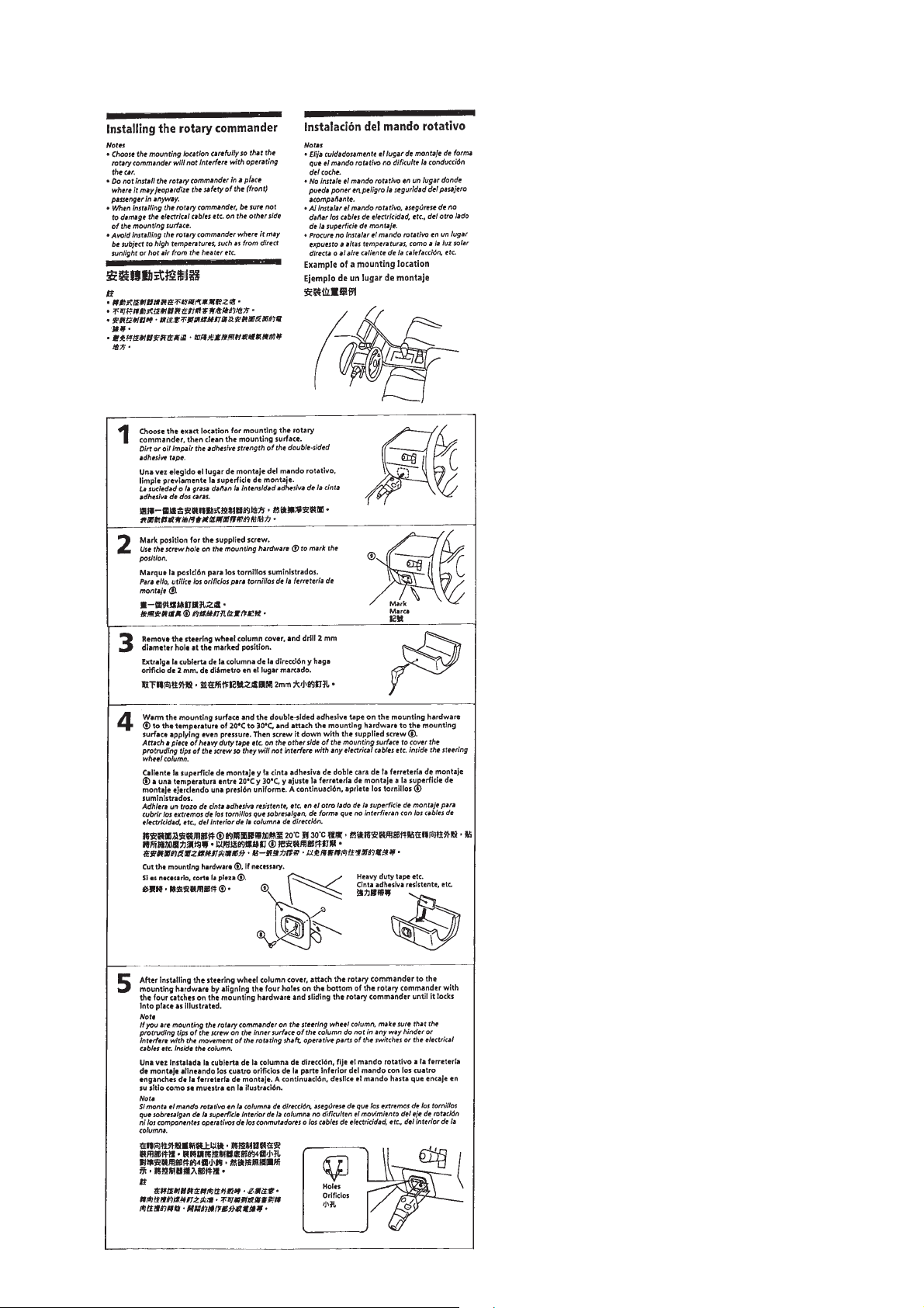
Preparing the Rotary Commander .................................. 6
Setting the Clock ............................................................. 6
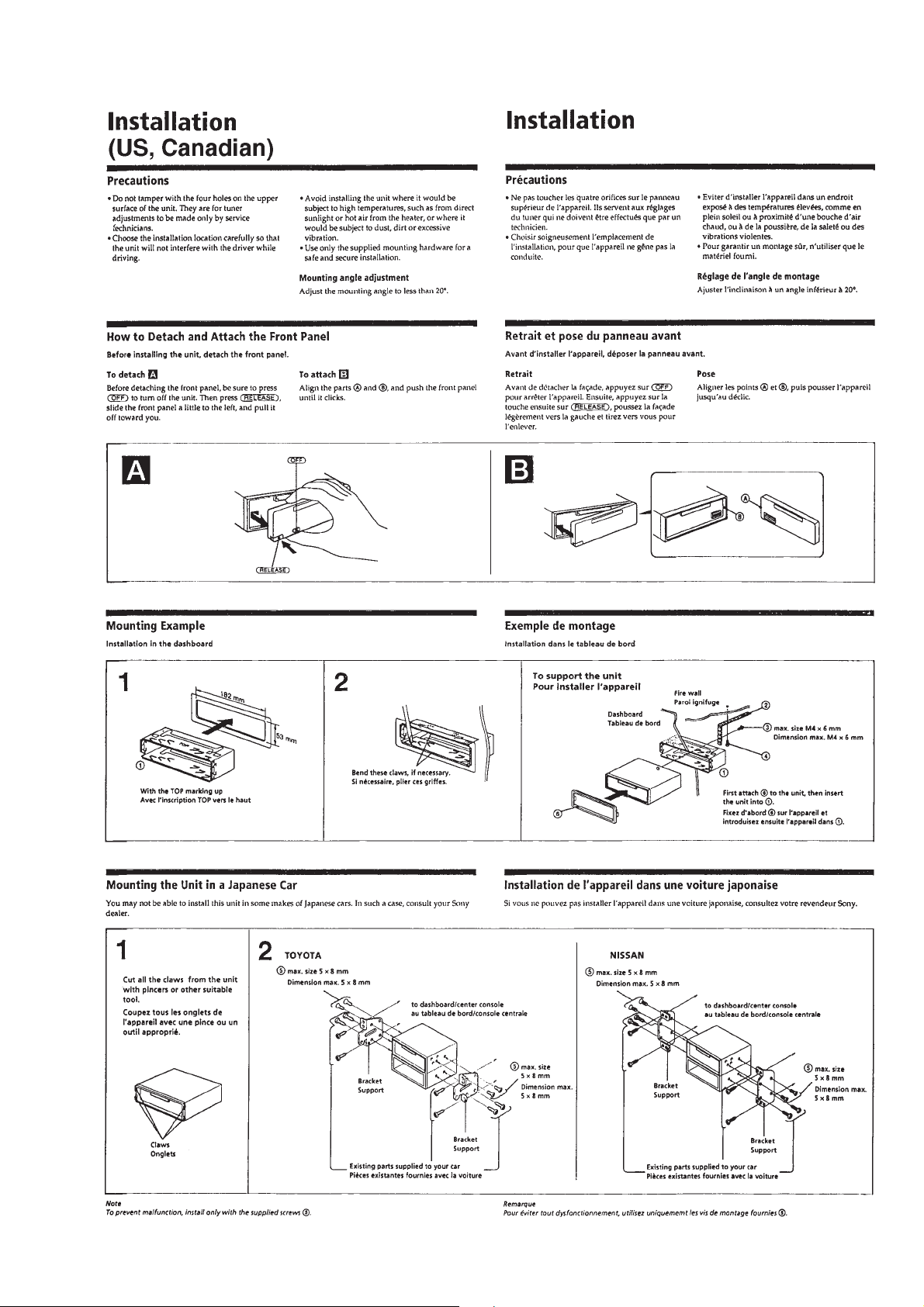
Installation (US, Canadian) ............................................ 7
Installation (AEP, UK, E) ............................................... 8
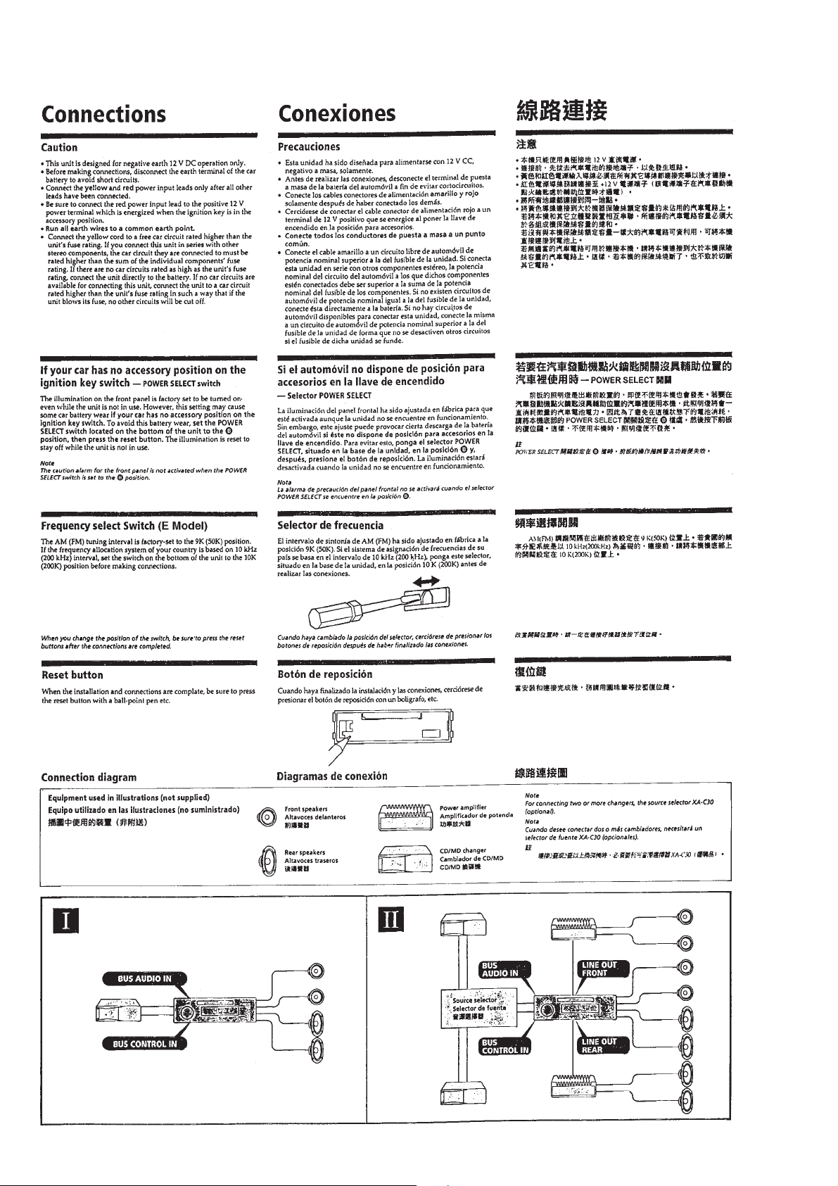
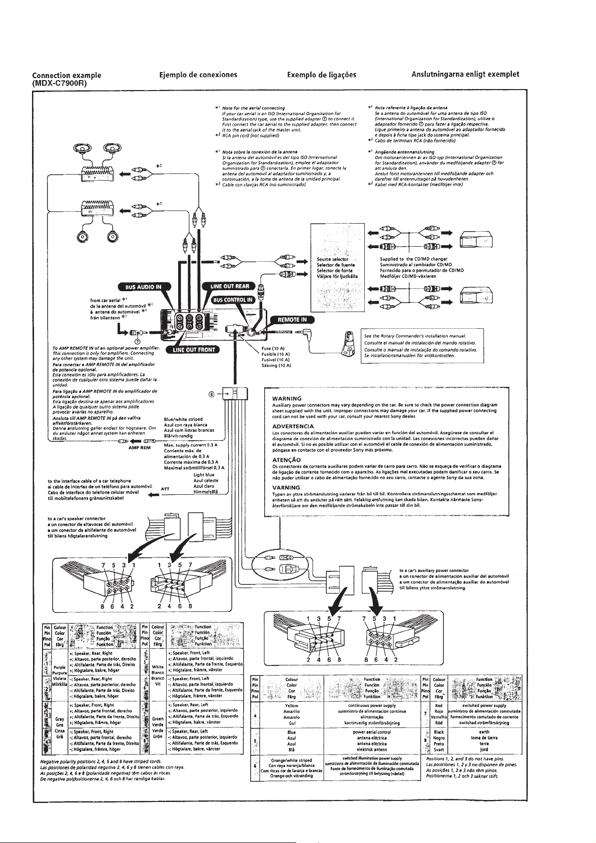
Connections ..................................................................... 10
3. DISASSEMBLY ......................................................... 13
4. ELECTRICAL ADJUSTMENTS
Test Mode........................................................................ 18
MD Section ..................................................................... 18
Tuner Section .................................................................. 18
5. DIAGRAMS
5-1. Block Diagram – SERVO Section – ............................... 21
5-2. Block Diagram – MAIN Section – ................................. 23
5-3. Block Diagram
– DISPLAY/KEY CONTROL Section –........................ 25
5-4. Block Diagram
– BUS CONTROL/POWER SUPPLY Section – ........... 27
5-5. Printed Wiring Boards
– MECHANISM DECK Section – ................................. 29
5-6. Schematic Diagram
– MECHANISM DECK Section – ................................. 31
5-7. Schematic Diagram – MAIN Section – .......................... 35
5-8. Pr inted Wiring Board – MAIN Section – ....................... 39
5-9. Pr inted Wiring Board – PANEL Section – ..................... 43
5-10. Schematic Diagram – PANEL Section –........................ 45
5-11. IC Pin Function Description ........................................... 55
6. EXPLODED VIEWS................................................ 64
7. ELECTRICAL PARTS LIST ...............................68
– 2 –
SECTION 1
SERVICE NOTE
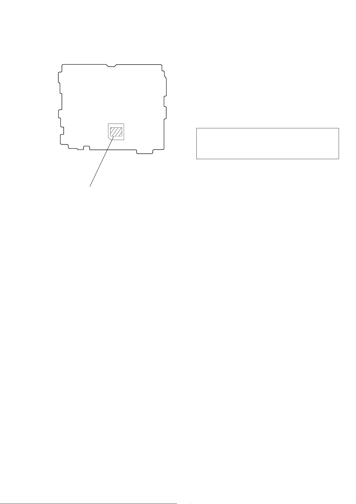
• Type A/B Discrimination
[MAIN BOARD] (Component Side)
IC700
MB90574PFV-G-113-BND (C7900R: Type A)
MB90574PFV-G-114-BND (C7900: Type A)
MB90F574PFV-G-113 (C7900R: Type B)
MB90F574PFV-G-114 (C7900: Type B)
Flexible Circuit Board Repairing
• Keep the temperature of the soldering iron around 270 ˚C during repairing.
• Do not touch the soldering iron on the same conductor of the
circuit board (within 3 times).
• Be careful not to apply force on the conductor when soldering
or unsoldering.
Notes on chip component replacement
• Never reuse a disconnected chip component.
• Notice that the minus side of a tantalum capacitor may be damaged by heat.
CAUTION
Use of controls or adjustments or performance of procedures
other than those specified herein may result in hazardous radiation exposure.
SAFETY-RELATED COMPONENT WARNING!!
COMPONENTS IDENTIFIED BY MARK ! OR DOTTED
LINE WITH MARK ! ON THE SCHEMATIC DIAGRAMS
AND IN THE PARTS LIST ARE CRITICAL TO SAFE
OPERATION. REPLACE THESE COMPONENTS WITH
SONY PARTS WHOSE PART NUMBERS APPEAR AS
SHOWN IN THIS MANUAL OR IN SUPPLEMENTS PUBLISHED BY SONY.
ATTENTION AU COMPOSANT AYANT RAPPORT
LES COMPOSANTS IDENTIFIÉS P AR UNE MARQUE !
SUR LES DIAGRAMMES SCHÉMATIQUES ET LA LISTE
DES PIÈCES SONT CRITIQUES POUR LA SÉCURITÉ
DE FONCTIONNEMENT. NE REMPLACER CES COMPOSANTS QUE PAR DES PIÈCES SONY DONT LES
NUMÉROS SONT DONNÉS DANS CE MANUEL OU
DANS LES SUPPLÉMENTS PUBLIÉS PAR SONY.
À LA SÉCURITÉ!
– 3 –

This section is extracted from
instruction manual.
SECTION 2
GENERAL
– 4 –
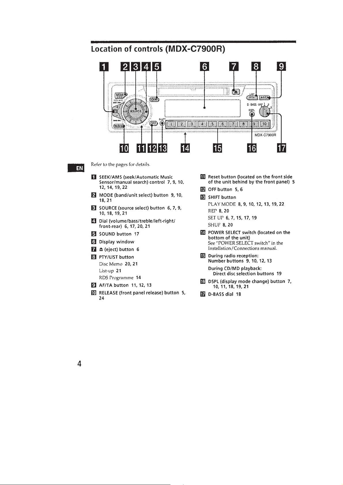
– 5 –
– 6 –
– 7 –

– 8 –
– 9 –
– 10 –

– 11 –
– 12 –
SECTION 3
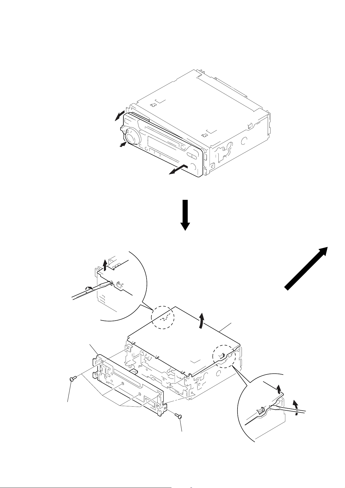
DISASSEMBLY
Note: Follow the disassembly procedure in the numerical order given.
FRONT PANEL
2
Push the button (release).
1
Remove the front panel of the arrow.
COVER ASS’Y, PANEL (SUB) ASS’Y
1
3
4
panel (sub) ass’y
3
four screws
(PTT2.6
2
cover ass’y
1
×
6)
3
screw
(PTT2.6
×
6)
– 13 –
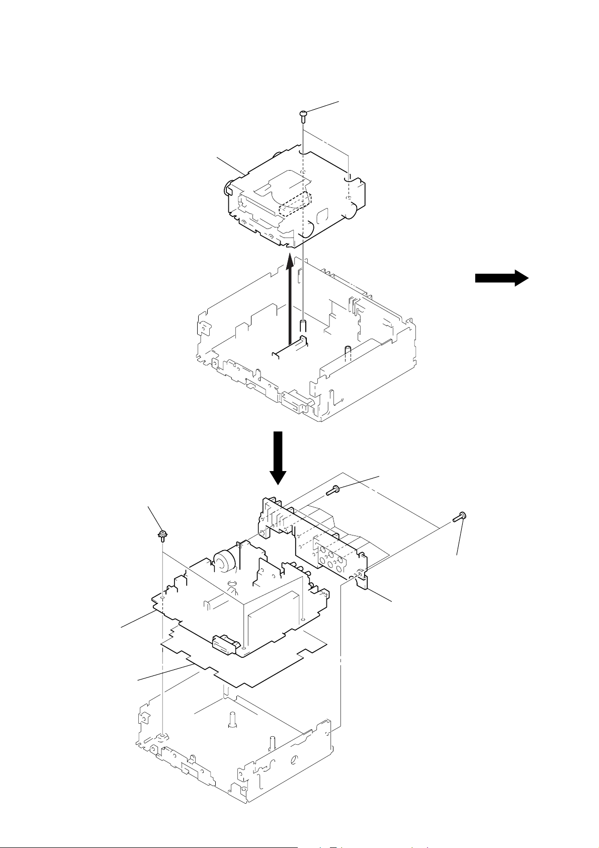
MECHANISM DECK (MG-164KT-138)
2
mechanism deck
(MG-164KT-138)
1
two screws
(PTT2.6
×
4)
MAIN BOARD
3
three screws
(PTT2.6
4
main board
5
insulating sheet
×
6) (ground point)
1
eight screws
(PTT2.6
2
heat sink
×
10)
1
two screws
(PTT2.6
×
10)
– 14 –
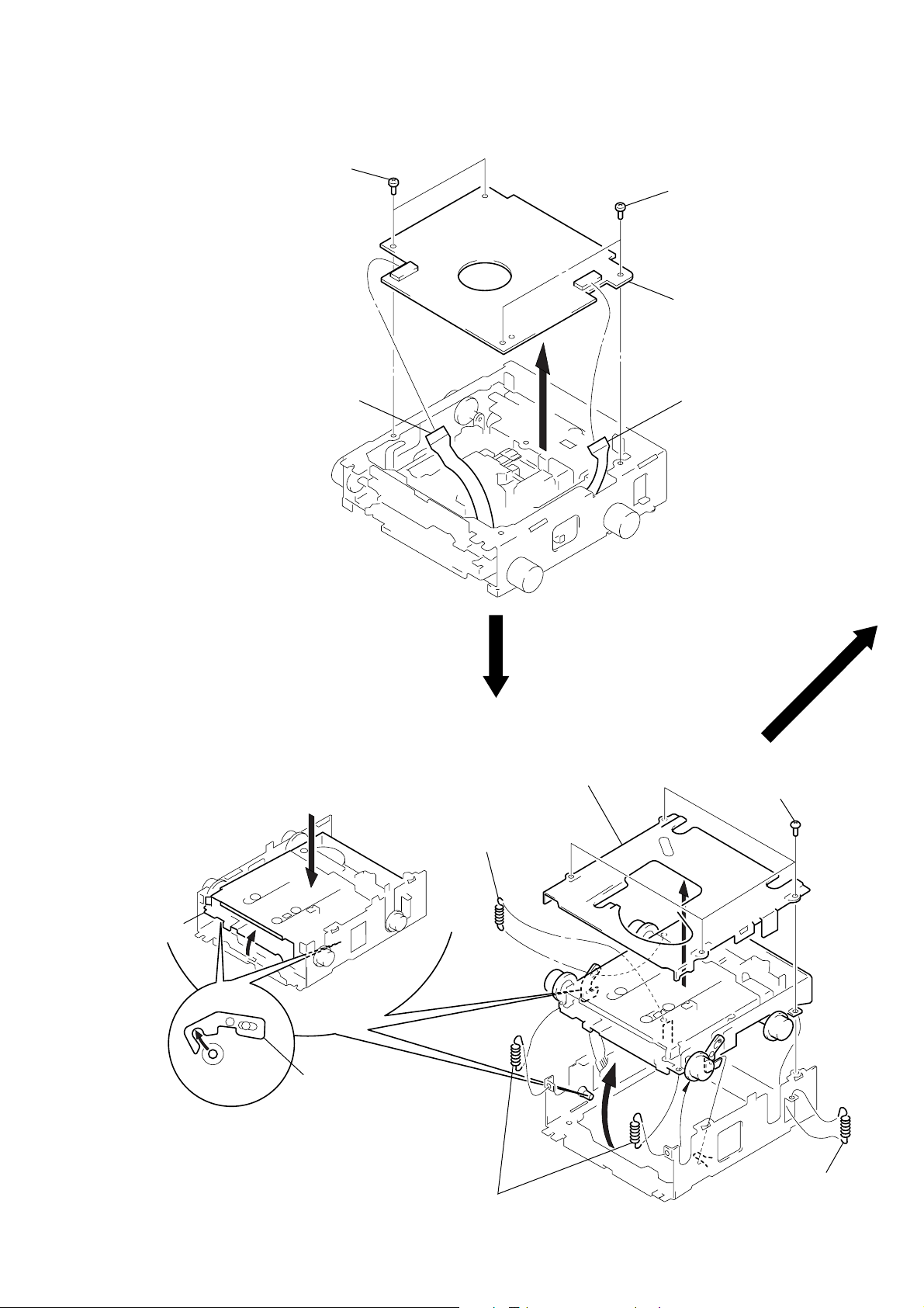
SERVO BOARD
)
3
two screws
(BVTT2
1
sensor flexible board
(CN102)
×
4)
3
two screws
(BVTT2
×
4)
4
servo board
2
flexible board
(CN103)
FLOAT BLOCK
float block
Release of the lock.
5
Pushing an arrw A part, raise
the float block up ward at the
front to release a lock.
A
lever (lock R)
lever (lock L)
3
spring (FL2)
2
MD cover ass’y
1
four screws
(BVTT2
×
4)
4
two springs (FL)
– 15 –
3
spring (FL2
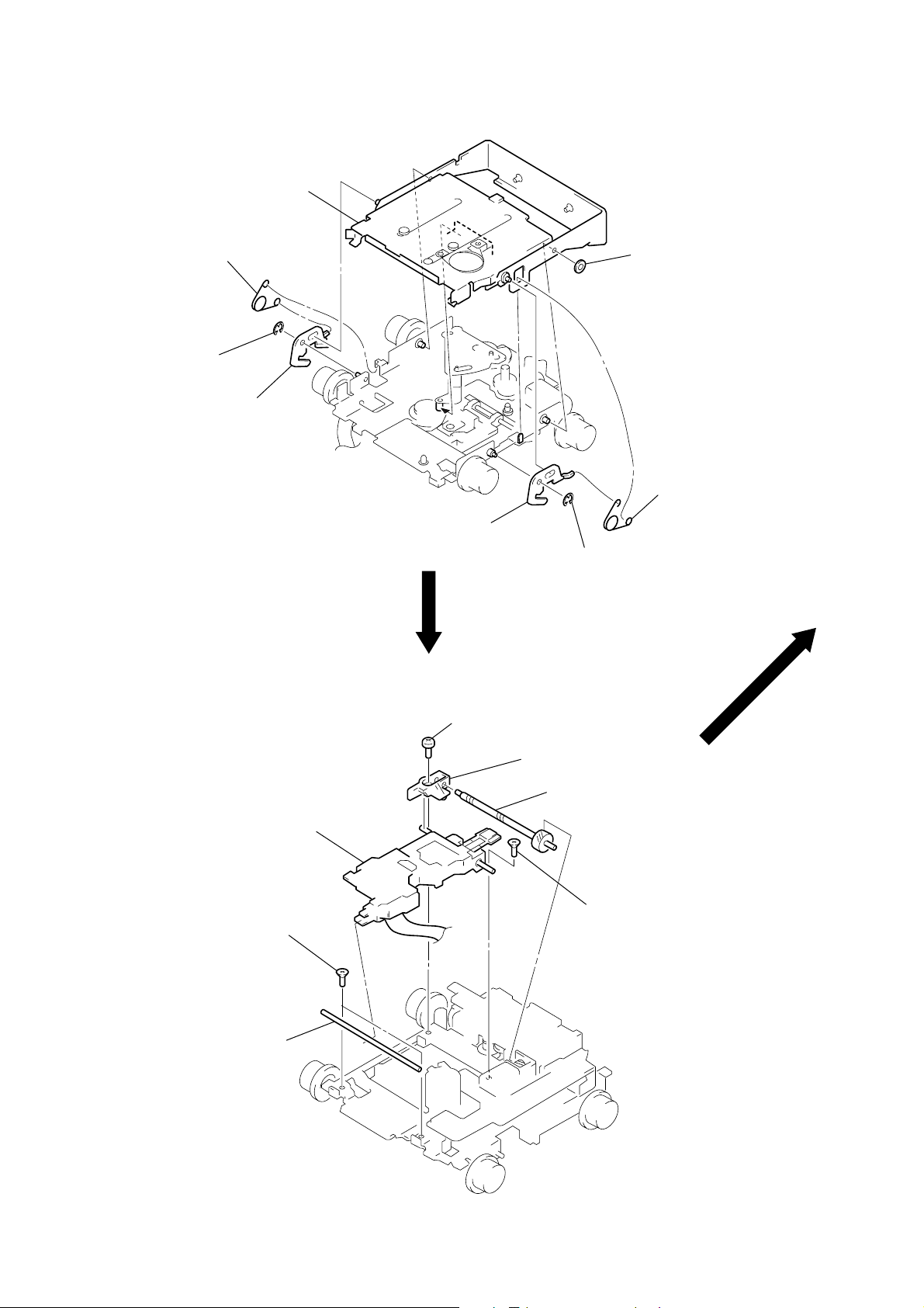
HOLDER ASS’Y
)
y
1
spring (CHKG)
2
stop ring E (1.5)
3
lever (lock R)
5
holder ass’y
3
lever (lock L)
2
stop ring E (1.5)
4
washer (M)
1
spring (CHKG
OPTICAL PICK-UP (KMS-241A/J2N)
7
optical pick-up
(KMS-241A/J2N)
1
two screws
(K2 × 3)
2
shaft (SL2)
4
screw
(B2 × 3)
6
bearing (SL)
5
feed screw ass’
3
screw
(K2 × 3)
– 16 –

MOTOR ASS’Y (M901, M902, M903), SENSOR BOARD
1
Remove the solders
of motor (M901, M902, M903).
3
sensor board
2
two screws
(2
×
8)
8
base (SL)
7
screw
(B2
×
3)
6
motor ass’y
(M902)
5
bracket (SL)
4
screw
(P1.7
×
1.8)
!¡
screw
(P2
×
2.2)
!™
motor ass’y
(M903)
0
motor ass’y
(M901)
9
two screws
(P1.7
×
1.8)
– 17 –
SECTION 4
ELECTRICAL ADJUSTMENTS
TEST MODE
This set have the test mode function. In the test mode, FM Auto
Scan/Stop Level and AM (MW) Auto Scan/Stop Lev el adjustments
can be performed easier than it in ordinary procedure.
<Set the Test Mode>
1. Set the “power select” switch (S700) is “A (ON)” position.
2. Turn ON the regulated power supply. (All LEDs on the set
lights up, and the clock is displayed.)
Note: Press the [OFF] button, if the clock is not displayed.
3. Push the preset [4] button.
4. Push the preset [5] button.
5. Press the preset [1] button for more than two seconds.
6. Then the display indicates all lights, the test mode is set.
<Release the Test mode>
1. Push the [OFF] button.
2. Return the “power select” switch (S700) to initially set position.
See the adjustment location from on page 20 for the adjustment.
MD SECTION
MD section adjustments are done automatically in this set.
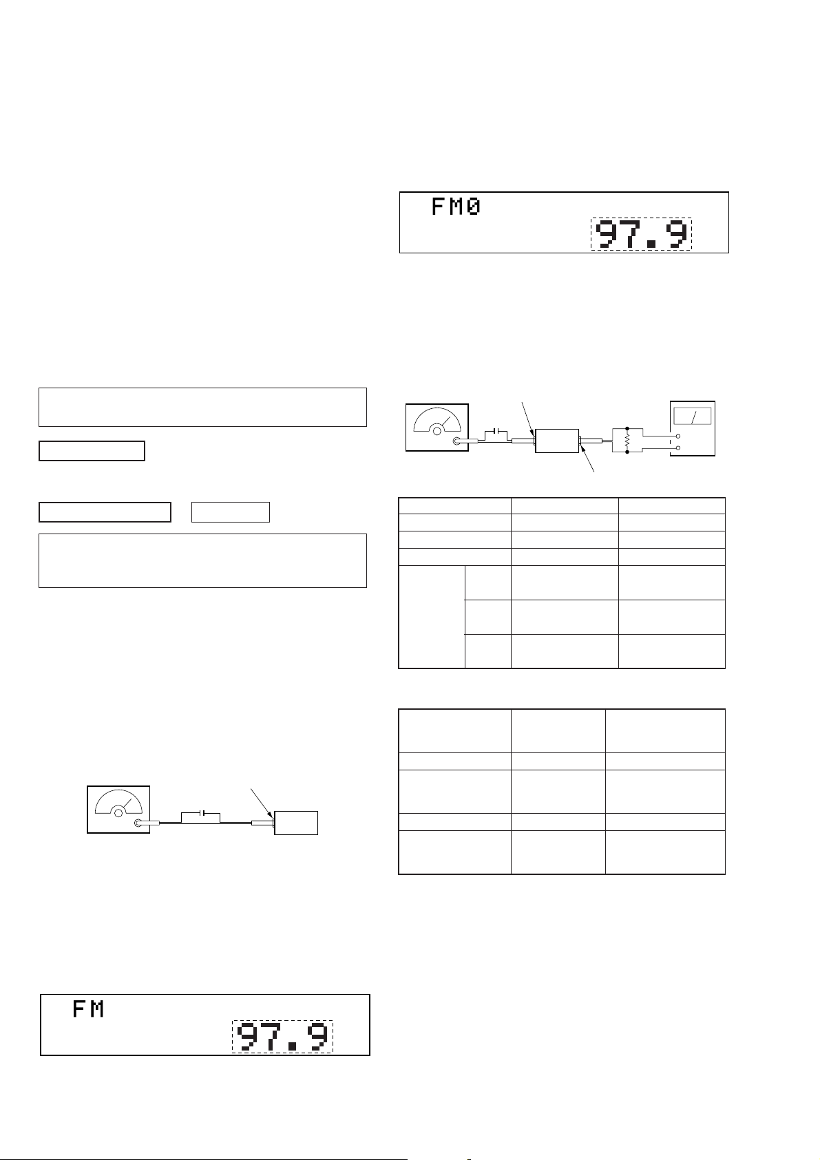
3. Adjust with the volume RV2 on TU1 so that the “FM” indication turns to “FM0” indication on the display window.
But, in case of already indicated “FM0”, turn the RV2 so that
put out light “0” indication and adjustment.
Display
*1
REG
SHUF
*1: MDX-C7900R is indicates “98.00”.
Adjustment Location: See page 20.
FM Stereo Separation Adjustment
Setting:
[SOURCE] button: FM
FM RF signal
generator
antenna jack (J1)
0.01 µF
4
set
speaker out terminal
level meter
Ω
+
–
TUNER SECTION
0 dB=1 µV
Cautions during repair
When the tuner unit is defective, replace it by a new one because its internal block is difficult to repair.
Note:
Adjust the tuner section in the sequence shown below.
1. FM Auto Scan/Stop Level Adjustment.
2. FM Stereo Separation Adjustmnet.
3. AM (MW) Auto Scan/Stop Level Adjustment.
4. RDS S-Meter Adjustment.
FM Auto Scan/Stop Level Adjustment
Setting:
[SOURCE] button: FM
FM RF signal
generator
Carrier frequency: 97.9 MHz (MDX-C7900)
Output level : 22 dB (12.6
Mode : mono
Modulation : 1 kHz, 22.5 kHz deviation (30%)
98.0 MHz (MDX-C7900R)
antenna jack (J1)
0.01 µF
µ
set
V)
Procedure:
1. Set to the test mode.
2. Push the [SOURCE] button and set to FM.
MDX-C7900 MDX-C7900R
Carrier frequency 97.9 MHz 98.0 MHz
Output level 60 dB (1 mV) 70 dB (3.2 mV)
Mode stereo stereo
main
Modulation sub
19 kHz 7.5 kHz 7.5 kHz
pilot deviation (10%) deviation (10%)
1 kHz, 33.75 kHz 1 kHz, 20 kHz
deviation (45%) deviation (22.6%)
1 kHz, 33.75 kHz 1 kHz, 20 kHz
deviation (45%) deviation (22.6%)
Procedure:
FM Stereo
signal generator
output channel
L-CH L-CH A
R-CH L-CH Adjust RV4 on TU1
R-CH R-CH C
L-CH R-CH Adjust RV4 on TU1
Level meter Level meter
connection reading (dB)
B
for minimum reading.
D
for minimum reading.
L-CH Stereo separation: A-B
R-CH Stereo separation: C-D
The separations of both channels should be equal.
Specification: Separation more than 30 dB
REG
Display
Adjustment Location: See page 20.
SHUF
*1
– 18 –
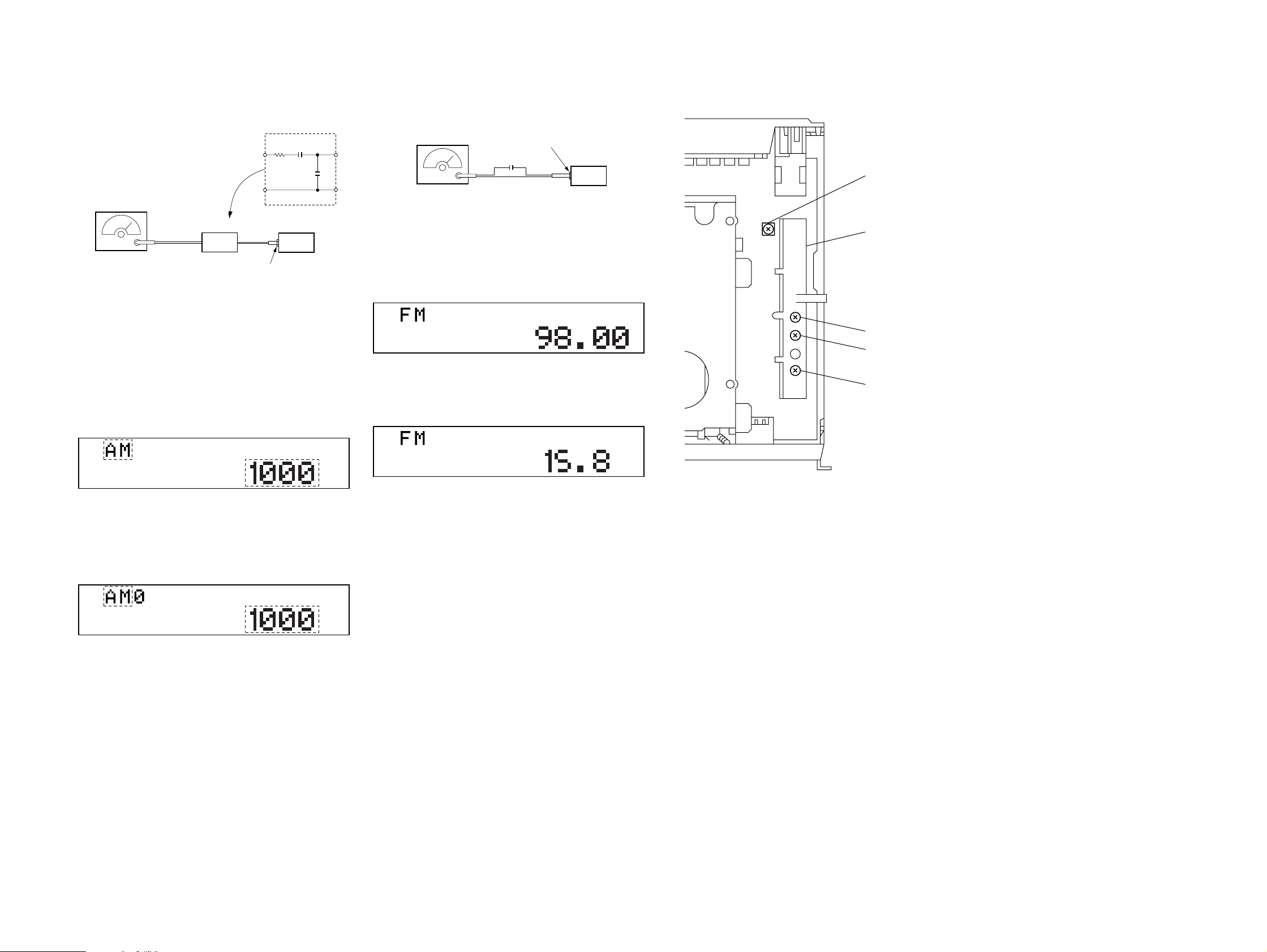
AM (MW) Auto Scan/Stop Level Adjustment
Setting:
[SOURCE] button (MDX-C7900): AM
[SOURCE] button (MDX-C7900R): MW
15 pF
30
Ω
65 pF
AM RF signal
generator
AM dummy antenna
(50 Ω)
antenna jack (J1)
Carrier frequency: 1000 kHz (MDX-C7900)
30% amplitude
modulation by
1 kHz signal
Output level : 33 dB (44.7
999 kHz (MDX-C7900R)
µ
V)
set
Procedure:
1. Set to the test mode. (See page 18.)
2. Push the [SOURCE] button and set to FM.
3. Push the [MODE] button and set to AM (MDX-C7900) or MW
(MDX-C7900R).
Display
*2
TP
REG
SHUF
*3
4. Adjust with the volume RV1 on TU1 so that the “ AM” or “MW”
indication turns to “AM0” or “MW0” indication on the display window.
But, in case of already indicated “AM0” or “MW0”, turn the
RV1 so that put out light “0” indication and adjustment.
RDS S-Meter Adjustment (MDX-C7900R)
Setting:
[SOURCE] button: FM
FM RF signal
generator
Carrier frequency: 98.0 MHz
Output level : 35 dB (56.2
Mode : mono
Modulation : no modulation
antenna jack (J1)
0.01 µF
µ
set
V)
Procedure:
1. Set to the test mode. (See page 18.)
2. Push the [SOURCE] button and set to FM.
Display
SHUF
REG
3. Push the preset [10] button.
4. Adjust RV1 on MAIN board so that the display indication is
“15.8”.
Display
SHUF
REG
Specification: Display indication : 15.6 to 16.4
Adjustment Location: See page 20.
Adjustment Location:
– SET UPPER VIEW –
RV1 RDS S-METER Adjustment
TU1
RV1 AM (MW) AUTO SCAN/STOP LEVEL Adjustment
RV2 FM AUTO SCAN/STOP LEVEL Adjustment
RV4 FM STEREO SEPARATION Adjustment
Display
*2
TP
REG
*2: MDX-C7900R is indicates “MW”.
*3: MDX-C7900R is indicates “999”.
Adjustment Location: See page 20.
SHUF
*3
– 19 – – 20 –
 Loading...