

Sony MDXC-670-RDS Service manual
MDX-C670/C670RDS
SERVICE MANUAL
US Model
Canadian Model
E Model
MDX-C670
AEP Model
UK Model
MDX-C670RDS
Refer to RM-X2S/X3S Service Manual (9-960-039∏) issued previously for information of remote
commander (RM-X2S) supplied with this set.
MD player section
Signal-to-noise ratio 90 dB
Frequency response 10 – 20,000 Hz
Wow and flutter Below measurable limit
Tuner section
FM
Tuning range MDX-C670 :
FM tuning interval :
50 kHz/200 kHz
switchable
87.5 – 108.0 MHz (at 50 kHz step)
87.5 – 107.9 MHz (at 200 kHz step)
MDX-C670RDS :
87.5 – 108.0 MHz
Aerial terminal External antenna connector
Intermediate frequency 10.7 MHz
Usable sensitivity 10 dBf
Selectivity 75 dB at 400 kHz
Signal-to-noise ratio 62 dB (stereo),
65 dB (mono)
Harmonic distortion at 1 kHz
0.9% (stereo),
0.5% (mono)
Separation 35 dB at 1 kHz
Frequency response 30 – 15,000 Hz
Capture ratio 2dB
Photo : MDX-C670RDS
SPECIFICATIONS
AM (MDX-C670)
Tuning range AM tuning interval :
MW/LW (MDX-C670RDS)
Tuning range MW : 531 – 1,602 kHz
Antenna terminal External antenna connector
Intermediate frequency 10.71 MHz/450 kHz
Sensitivity AM, MW : 30 µV
Power amplifier section
Outputs Speaker outputs
Speaker impedance 4 – 8 ohms
Maximum power output 35 W × 4 (at 4 ohms)
Model Name Using Similar Mechanism NEW
Base Mechanism Type
Optical Pick-up Name KMS-241A/J2N
9 kHz/10 kHz switchable
531 – 1,602 kHz (at 9 kHz step)
530 – 1,710 kHz (at 10 kHz step)
LW : 153 – 281 kHz
LW : 50 µV
(sure seal connectors)
– Continued on next page –
MG-164K-138
MDX-C670
FM/AM MINIDISC PLAYER
MDX-C670RDS
MICROFILM
FM/MW/LW MINIDISC PLAYER
General
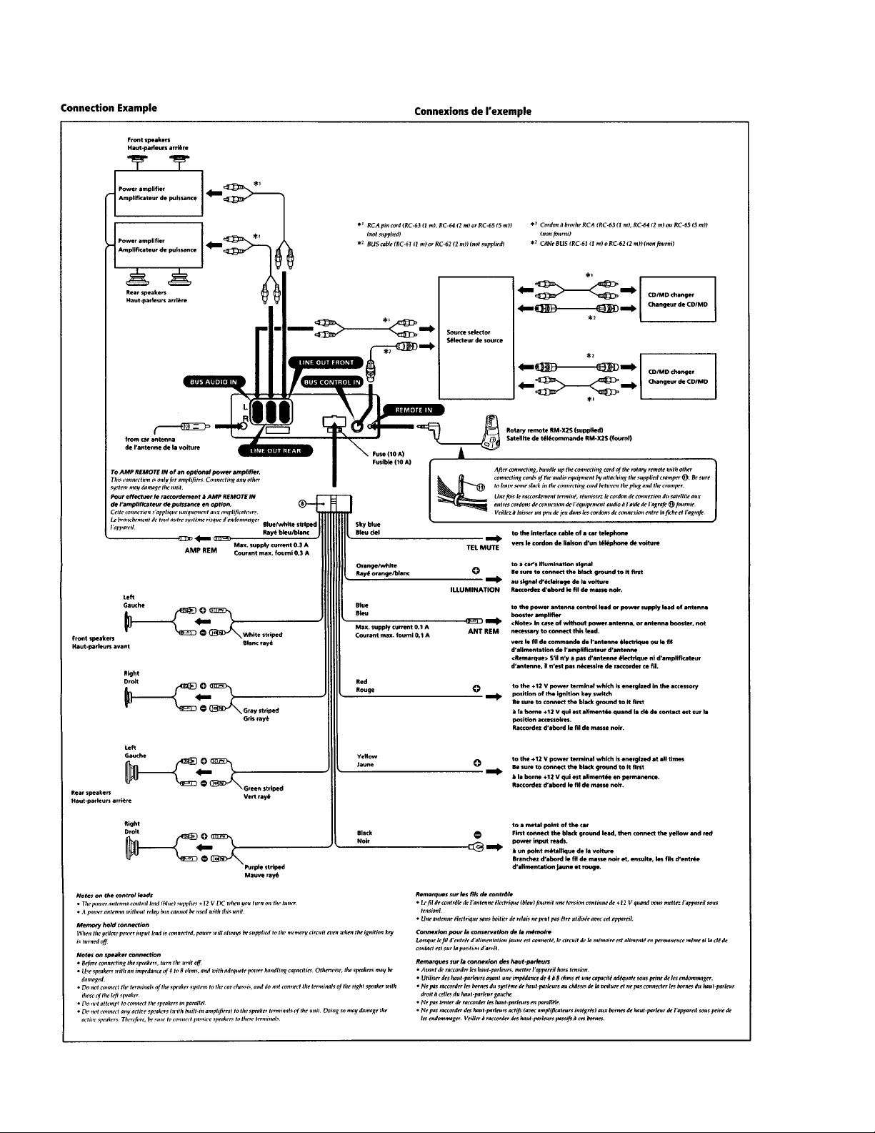
Output Line out (2)
Power antenna relay control lead
Power amplisier control lead
Telephone mute control lead (MDX-C670)
Illumination control lead
Tone controls Bass ± 10 dB at 100 Hz
Treble ± 10 dB at 10 kHz
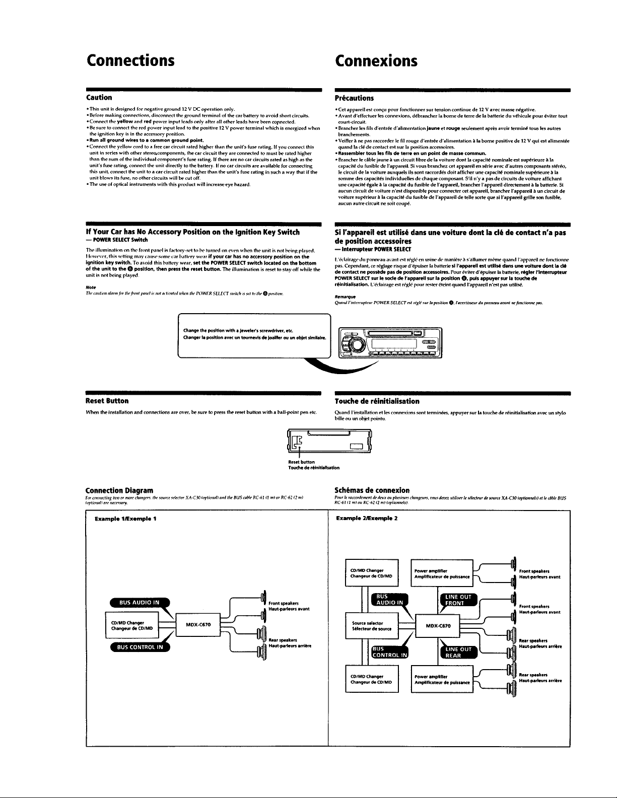
Power requirements 12 V DC car battery (negative ground)
Dimensions Approx. 188 × 58 × 174 mm (w/h/d)
Mounting dimensions Approx. 178 × 50 × 162 mm (w/h/d)
Mass Approx. 1.1 kg
Supplied accessories Rotary remote (1)
Parts for installation and connections (1 set)
Front panel case (1)
U.S. and foreign patents liscensed from Dolby laboratories Licensing Corporation.
Design and specifications are subject to change without notice.
Flexible Circuit Board Repairing
• Keep the temperature of the soldering iron around 270 ˚C
during repairing.
• Do not touch the soldering iron on the same conductor of
the circuit board (within 3 times).
• Be careful not to apply force on the conductor when solder-
ing or unsoldering.
Notes on chip component replacement
• Never reuse a disconnected chip component.
• Notice that the minus side of a tantalum capacitor may be
damaged by heat.
CAUTION
Use of controls or adjustments or performance of procedures other than those specified herein may result in
hazardous radiation exposure.
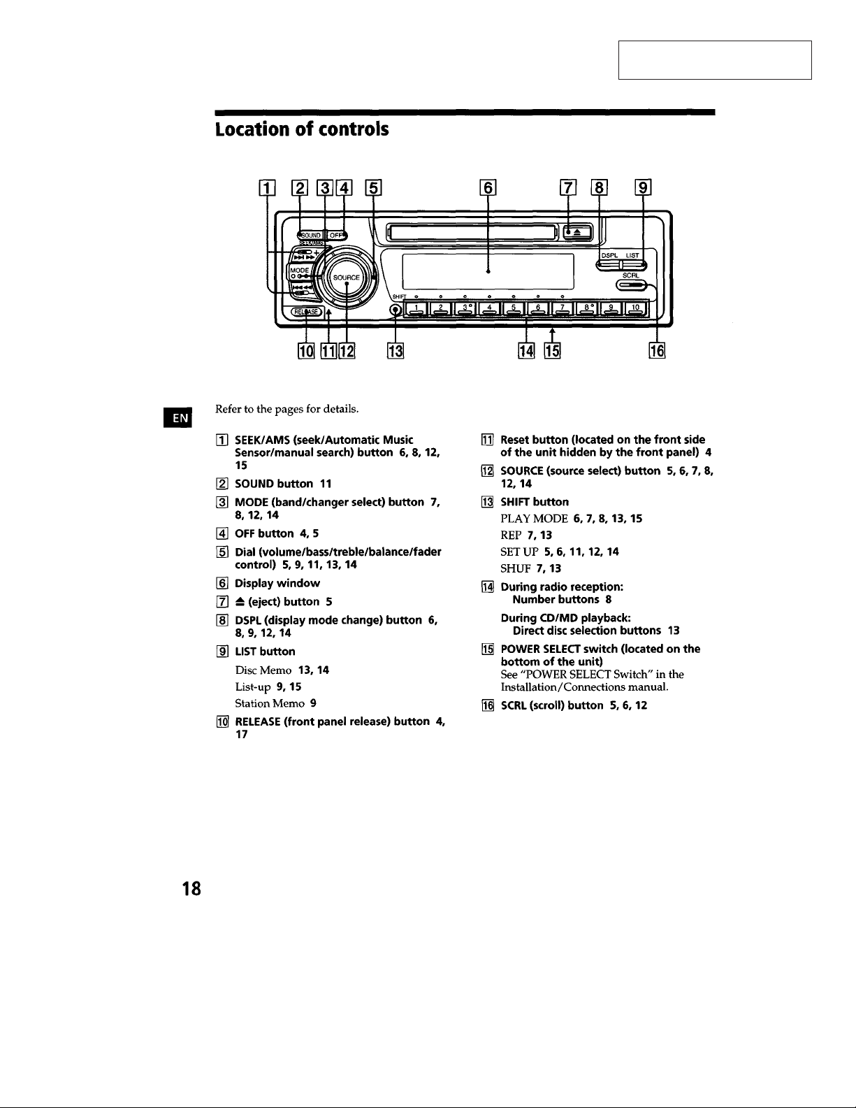
TABLE OF CONTENTS
1. SERVICE NOTE ......................................................... 2
2. GENERAL ..................................................................... 3
3. DISASSEMBLY............................................................ 7
4. ELECTRICAL ADJUSTMENTS ........................... 12
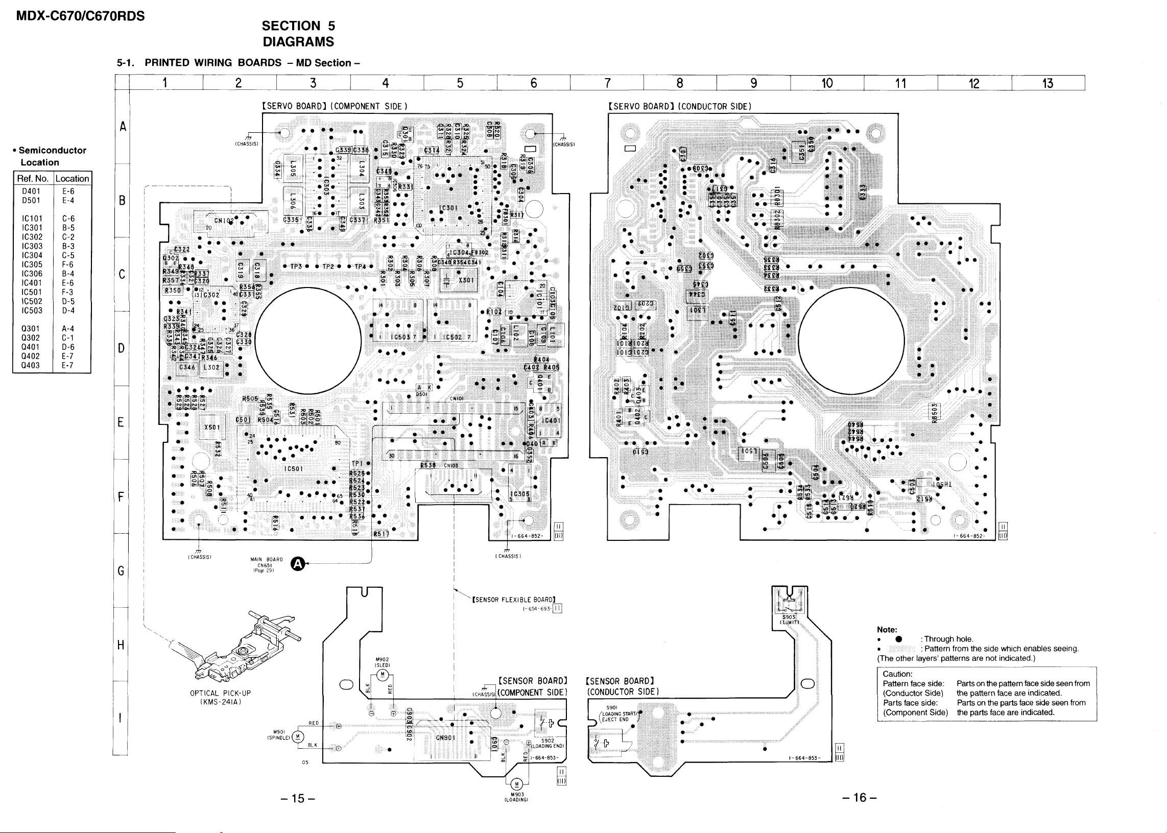
5. DIAGRAMS
5-1. Printed Wiring Boards –MD Section– .............................. 15
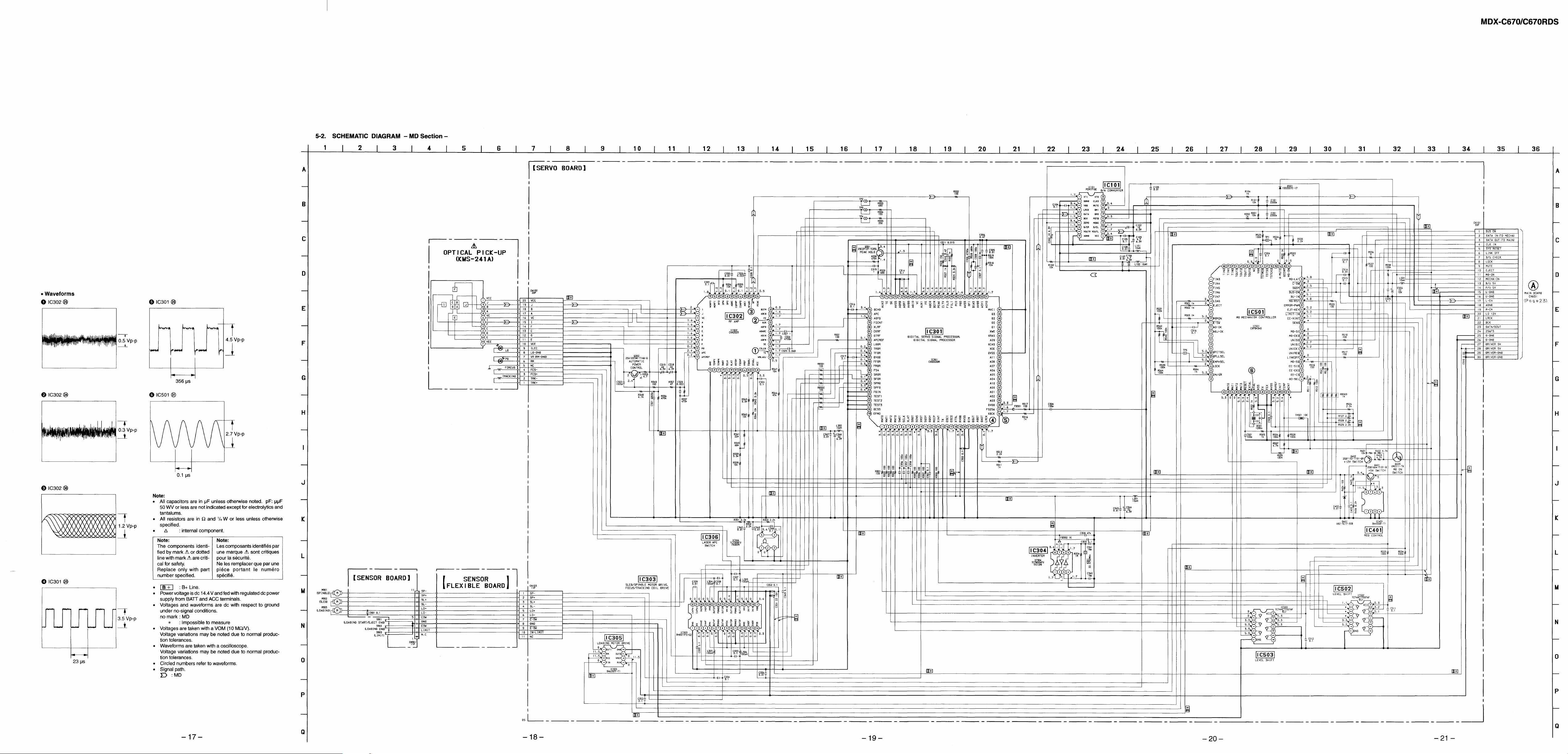
5-2. Schematic Diagram –MD Section– .................................. 17
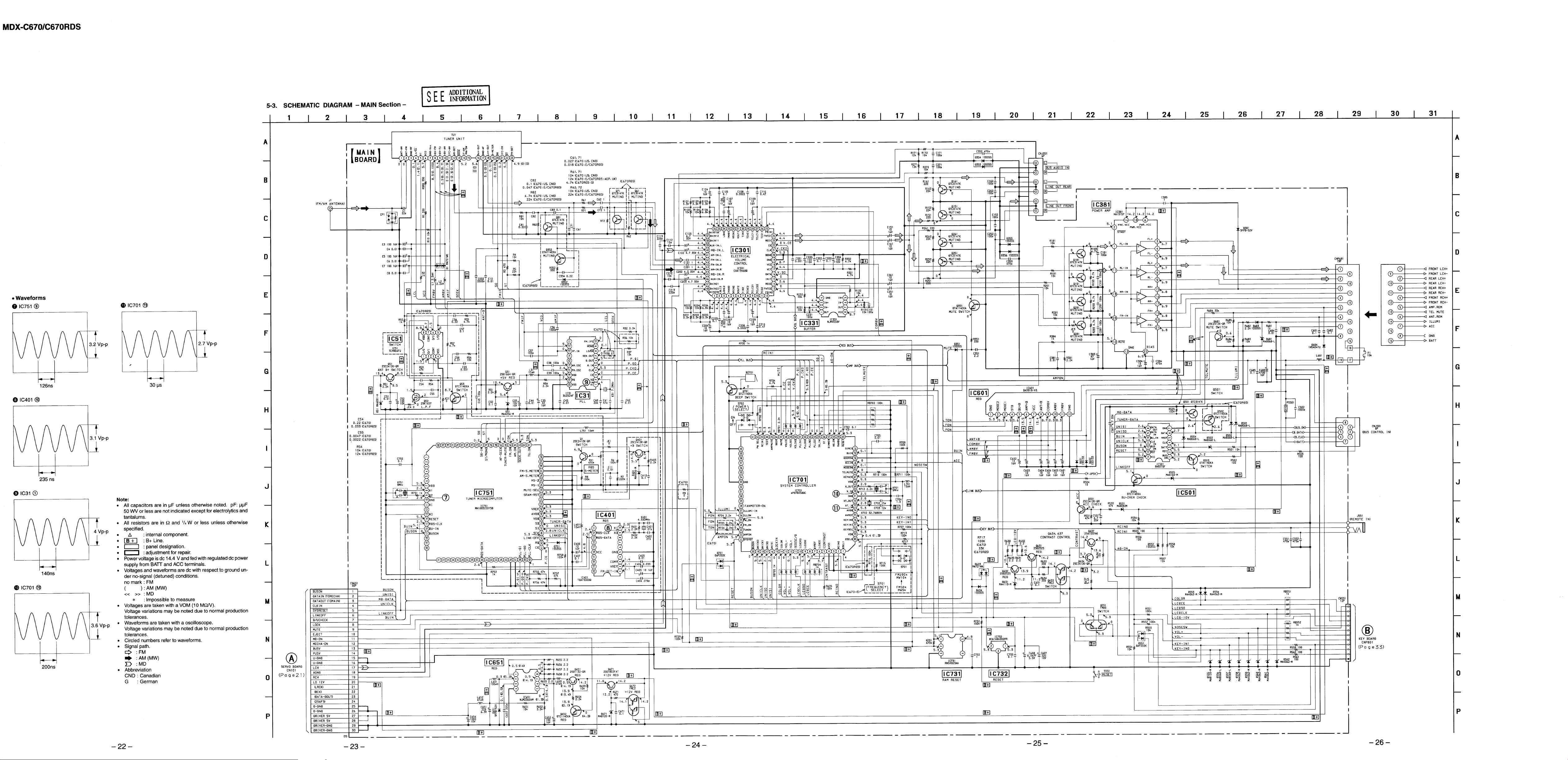
5-3. Schematic Diagram –MAIN Section–.............................. 22
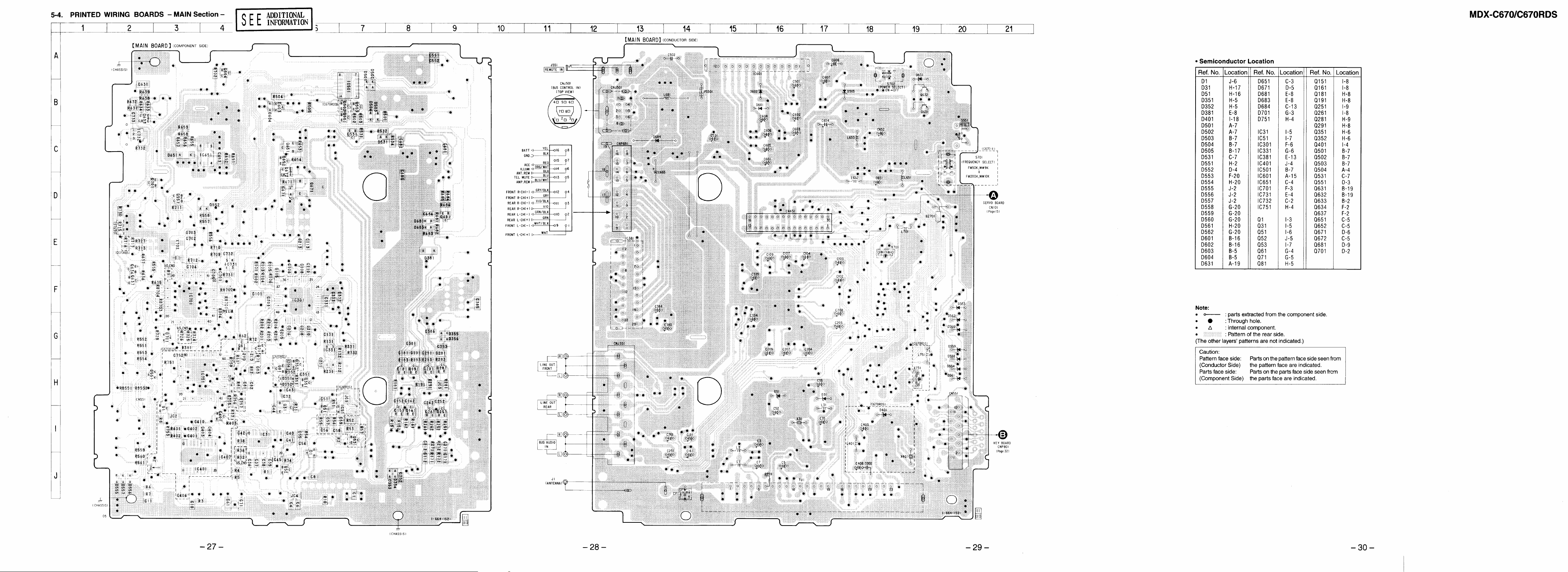
5-4. Printed Wiring Board –MAIN Section– ........................... 27
5-5. Printed Wiring Board –DISPLAY Section– ..................... 31
5-6. Schematic Diagram –DISPLAY Section– ........................ 33
6. EXPLODED VIEWS .................................................. 35
7. ELECTRICAL PARTS LIST.................................. 39
SECTION 1
SERVICE NOTE
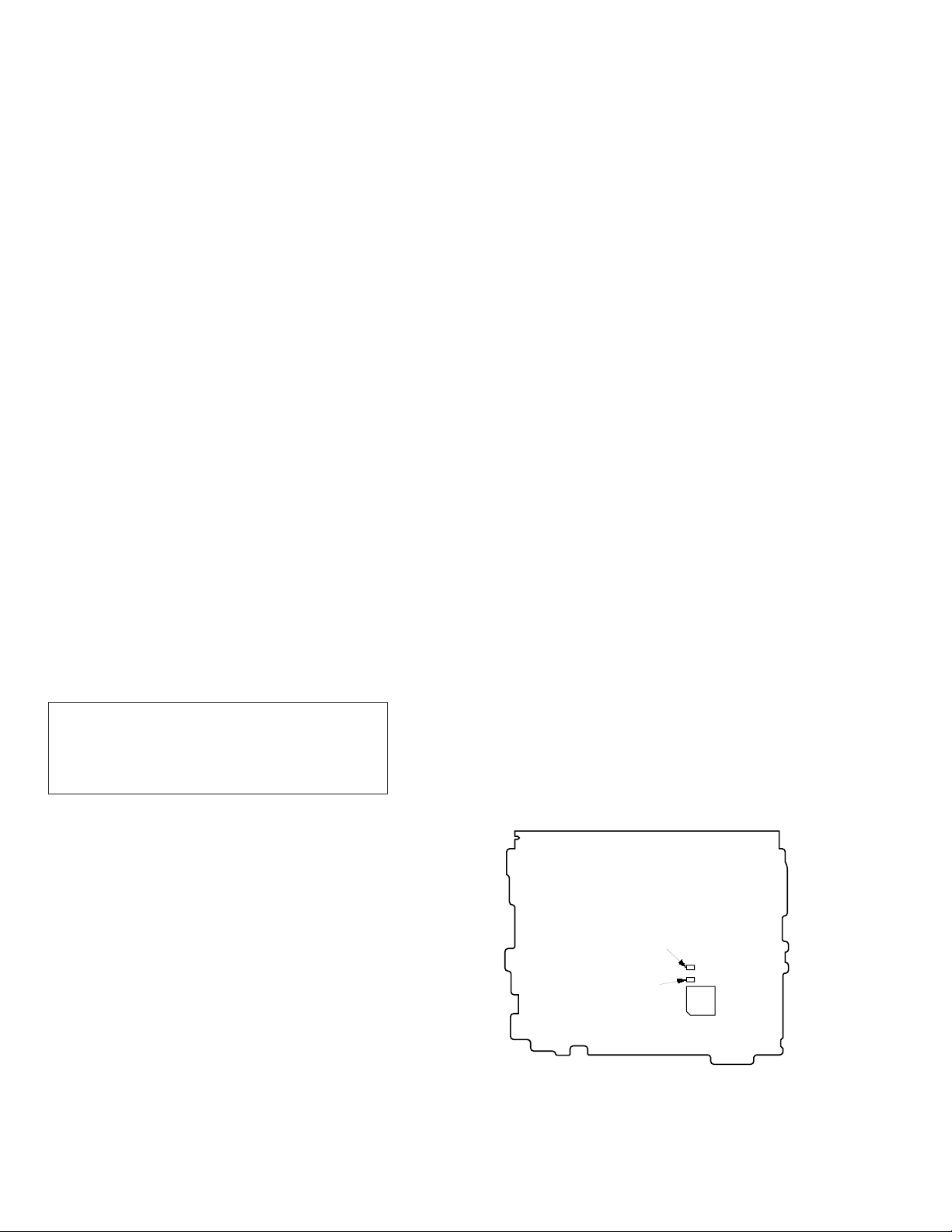
• Note on replacing the MAIN board (German model)
As the repair parts of MAIN board with mounted parts destined for
German model, the MAIN board with mounted parts for AEP model
is supplied.
Accordingly, when replacing the board, exchange two following
parts.
R61 12k n 4.7k (1-216-065-00)
R71 12k n 4.7k (1-216-065-00)
SAFETY-RELATED COMPONENT WARNING!!
COMPONENTS IDENTIFIED BY MARK ! OR DOTTED
LINE WITH MARK ! ON THE SCHEMATIC DIAGRAMS
AND IN THE PARTS LIST ARE CRITICAL TO SAFE
OPERATION. REPLACE THESE COMPONENTS WITH
SONY PARTS WHOSE PART NUMBERS APPEAR AS
SHOWN IN THIS MANUAL OR IN SUPPLEMENTS
PUBLISHED BY SONY.
ATTENTION AU COMPOSANT AYANT RAPPORT
À LA SÉCURITÉ!
LES COMPOSANTS IDENTIFIÉS PAR UNE MARQUE !
SUR LES DIAGRAMMES SCHÉMATIQUES ET LA LISTE
DES PIÈCES SONT CRITIQUES POUR LA SÉCURITÉ
DE FONCTIONNEMENT. NE REMPLACER CES COMPOSANTS QUE PAR DES PIÈCES SONY DONT LES
NUMÉROS SONT DONNÉS DANS CE MANUEL OU D ANS
LES SUPPLÉMENTS PUBLIÉS PAR SONY.
[MAIN BOARD] (Conductor Side)
R71
R61
IC751
– 2 –
SECTION 2
GENERAL
This section is extracted from
MDX-C670 instruction manual.
– 3 –
– 4 –
– 5 –
– 6 –
SECTION 3
DISASSEMBLY
Note: Follow the disassembly procedure in the numerical order given.
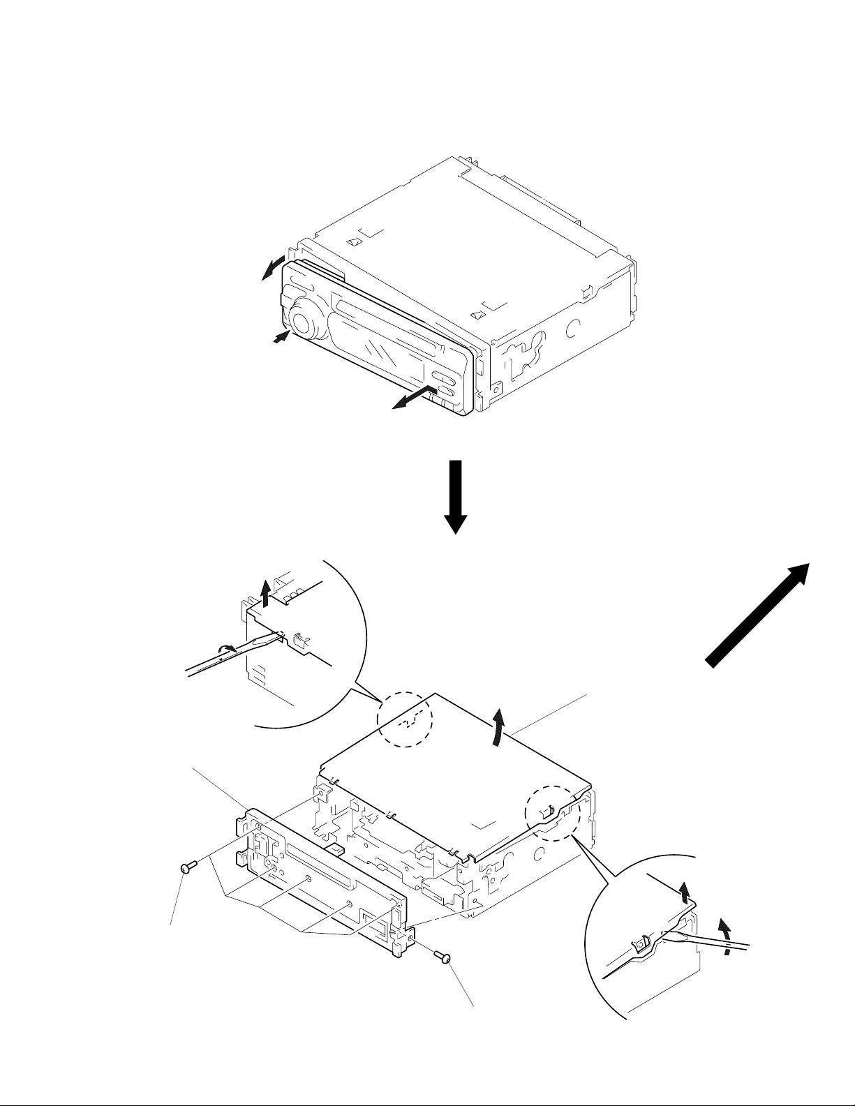
FRONT PANEL
2
Push the button (release).
1
COVER ASS’Y, PANEL (SUB) ASS’Y
1
3
Remove the front panel of the arrow.
2
cover ass’y
4
panel (sub) ass’y
3
five screws
(PTT2.6 × 6)
3
– 7 –
1
screw
(PTT2.6 × 6)
MECHANISM DECK (MG-164K-138)
2
mechanism deck
(MG-164K-138)
1
two screws
(PTT2.6 × 4)
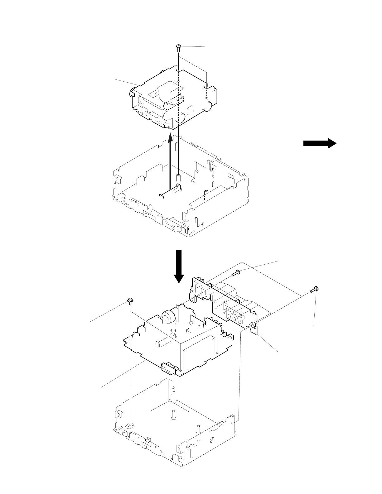
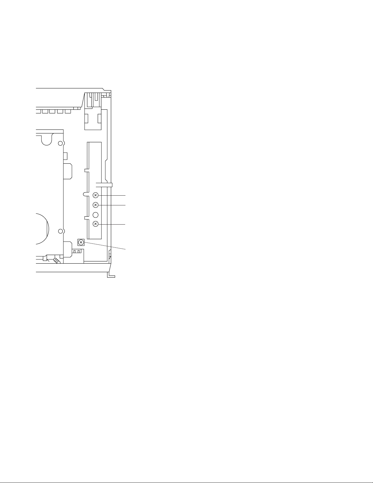
MAIN BOARD
3
three screws
(PTT2.6 × 6) (ground point)
4
main board
1
eight screws
(PTT2.6 × 8)
2
heat sink
1
two screws
(PTT2.6 × 8)
– 8 –

SERVO BOARD
1
sensor flexible board
(CN102)
3
two screws
(BVTT2 × 4)
3
two screws
(BVTT2 × 4)
4
servo board
2
flexible board
(CN103)
FLOAT BLOCK
5
Pushing an arrow A part, raise
the float block up ward at the
front to release a lock.
float block
Release of the lock.
A
lever (lock R)
lever (lock L)
3
spring (FL2)
2
MD cover ass’y
1
four screws
(BVTT2 × 4)
4
two springs (FL)
– 9 –
3
spring (FL2)
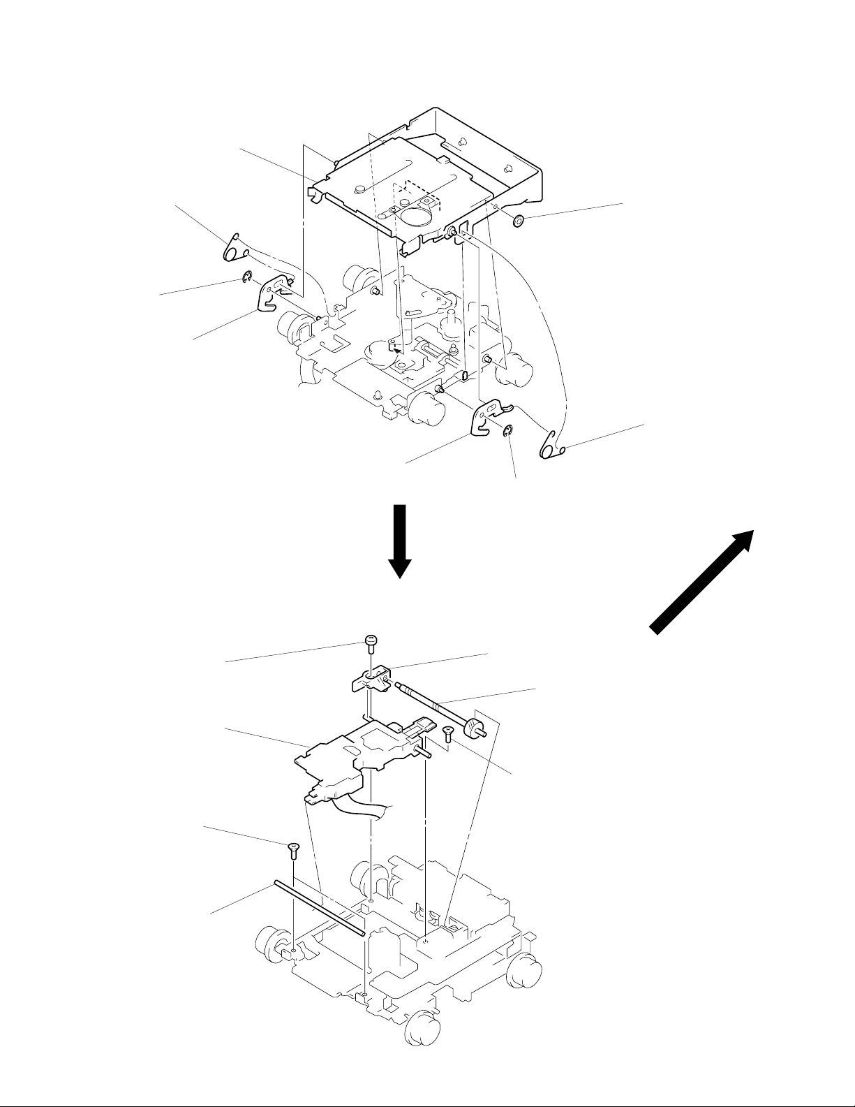
HOLDER ASS’Y
1
spring (CHKG)
2
stop ring E (1.5)
3
lever (lock R)
6
holder ass’y
4
lever (lock L)
2
stop ring E (1.5)
5
washer (M)
1
spring (CHKG)
OPTICAL PICK-UP (MD) (KMS-241A/J2N)
4
screw
(B2 × 3)
7
optical pick-up (MD)
(KMS-241A/J2N)
1
two screws
(K2 × 3)
2
shaft (SL2)
6
bearing (SL)
3
screw
(K2 × 3)
5
feed screw ass’y
– 10 –
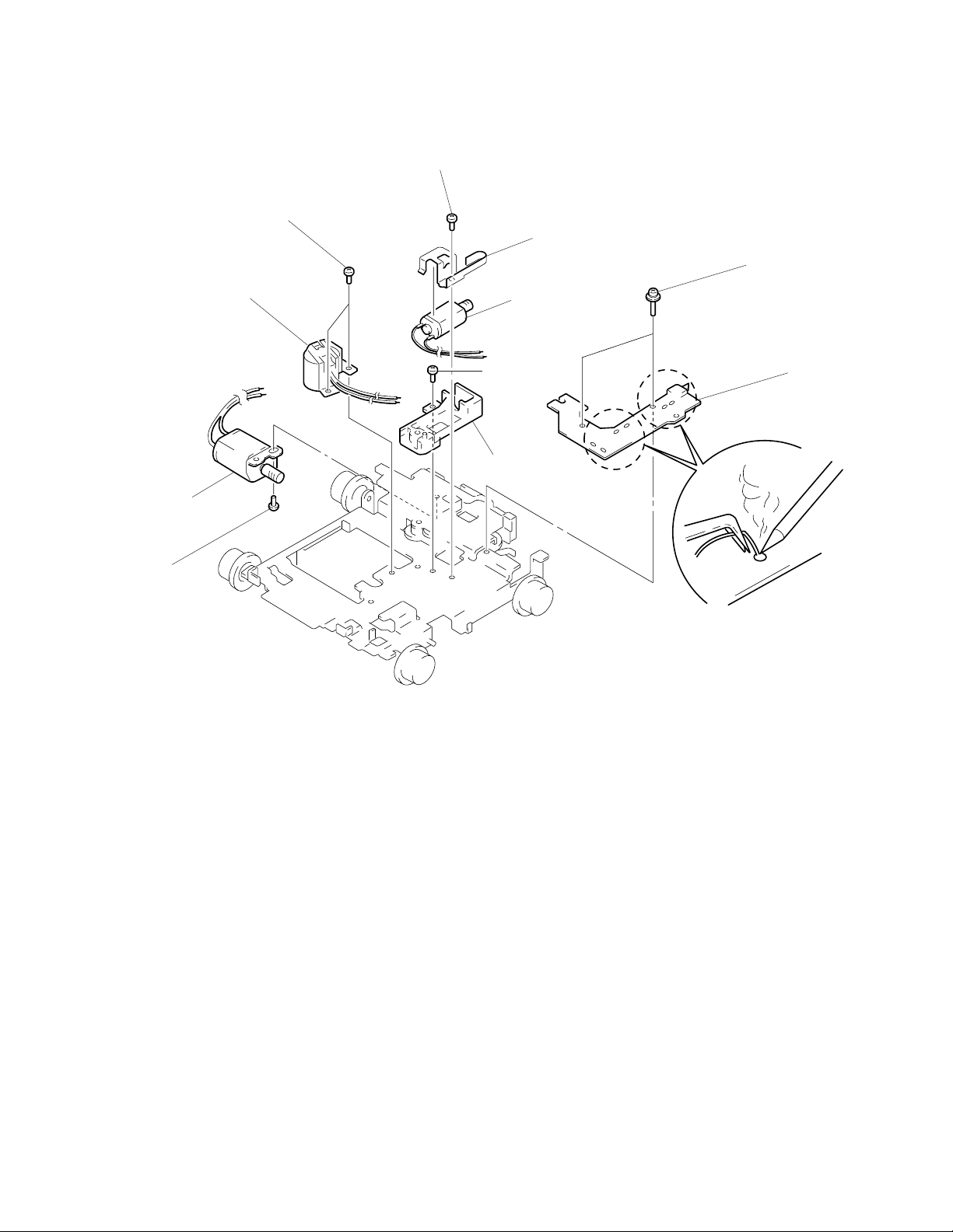
MOTOR ASS’Y (M901, M902, M903), SENSOR BOARD
4
screw (P1.7 × 1.8)
9
two screws
(P1.7 × 1.8)
0
motor ass’y
(M901)
7
8
!™
motor ass’y
(M903)
!¡
screw
(P2 × 2.2)
5
6
motor ass’y
(M902)
screw
(B2 × 3)
base (SL)
bracket (SL)
2
two screws
(2 × 8)
3
sensor board
1
Remove the solders
of motor (M901, M902, M903).
– 11 –
SECTION 4
ELECTRICAL ADJUSTMENTS
TEST MODE
This set have the test mode function. In the test mode, FM Auto
Scan/Stop Level and AM (MW) Auto Scan/Stop Level adjustments
can be performed easier than it in ordinary procedure.
4. Adjust with the volume RV2 on TU1 so that the “FM” indication turns to “FM0” indication on the display window.
But, in case of already indicated “FM0”, turn the RV2 so that
put out light “0” indication and adjustment.
<Set the Test Mode>
1. Set the “power select” switch (S702) is “ON” position.
2. Turn ON the regulated po wer supply . (All LEDs on the set lights
up, and the clock is displayed.)
Note: Press the OFF button, if the clock is not displayed.
3. Push the preset 4 button.
4. Push the preset 5 button.
5. Press the preset 1 button for more than two seconds.
6. Then the display indicates all lights, the test mode is set.
<Release the Test mode>
1. Push the OFF button.
MD SECTION
MD section adjustments are done automatically in this set.
TUNER SECTION
0dB=1µV
Cautions during repair
When the tuner unit is defective, replace it by a new one because
its internal block is difficult to repair.
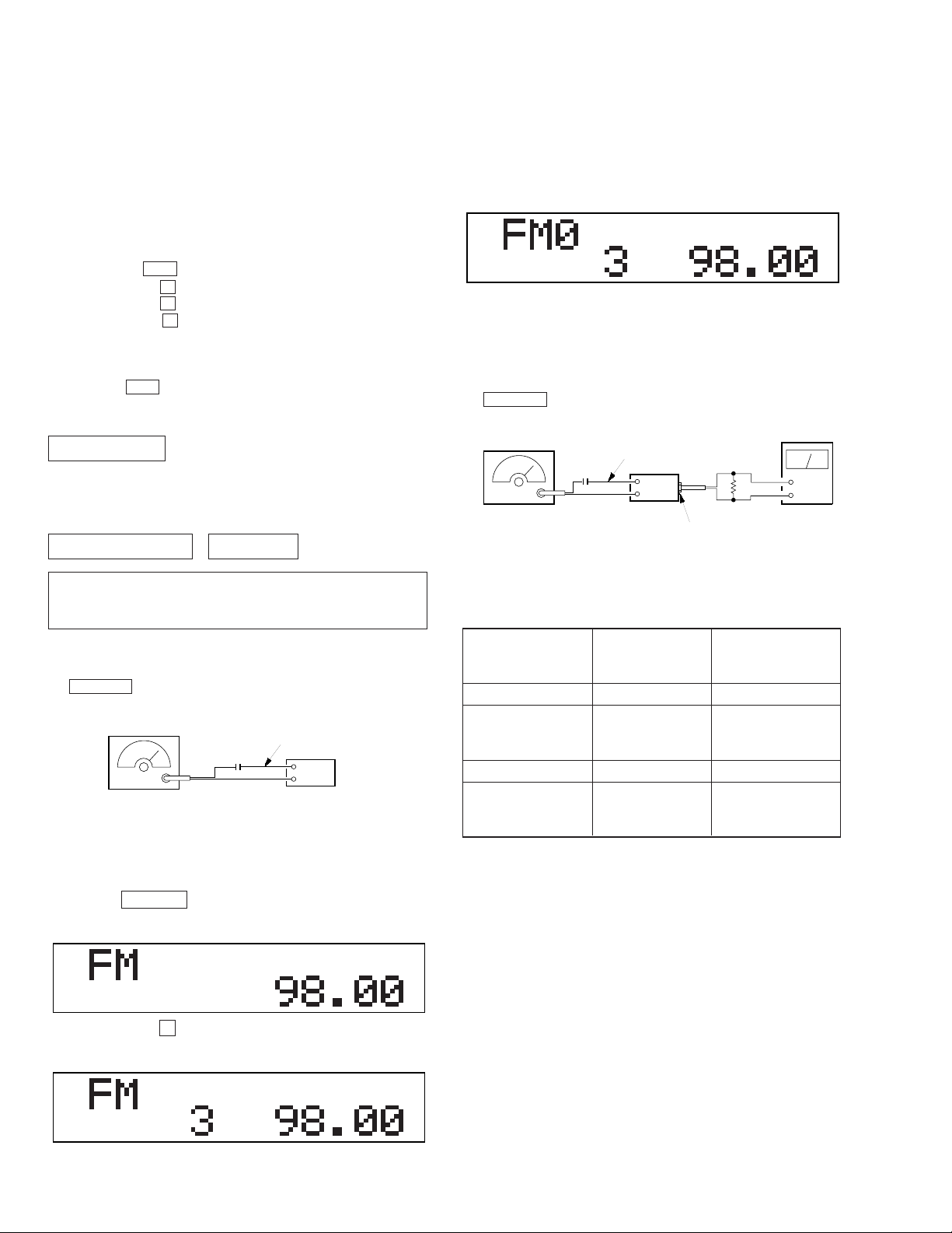
FM Auto Scan/Stop Level Adjustment
Setting:
SOURCE button: FM
FM RF signal
generator
0.01µF
Carrier frequency : 98.0 MHz
Output level : 22 dB (12.6
Mode : mono
Modulation : 1 kHz, 22.5 kHz deviation (30%)
antenna
terminal
µ
V)
set
Display
REG
Adjustment Location: See page 14.
FM Stereo Separation Adjustment
Setting:
SOURCE button: FM
FM RF signal
generator
0.01µF
Carrier frequency : 98.0 MHz
Output level : 70 dB (3.2 mV)
Mode : stereo
Modulation : main: 1 kHz, 33.75 kHz deviation (45%)
sub: 1 kHz, 33.75 kHz deviation (45%)
19 kHz pilot: 7.5 kHz deviation (10%)
antenna
terminal
set
10 k
LINE OUT
Procedure:
FM Stereo
signal generator
output channel
Level meter Level meter
connection reading (dB)
L-CH L-CH A
R-CH L-CH Adjust RV4 on TU1
for minimum reading.
R-CH R-CH C
L-CH R-CH Adjust RV4 on TU1
for minimum reading.
SHUF1
VTVM
Ω
+
–
B
D
Procedure:
1. Set to the test mode. (See page 12).
2. Push the SOURCE button and set to FM.
Display
REG
3. Push the preset 3 button.
Display
REG
SHUF1
SHUF1
L-CH Stereo separation: A-B
R-CH Stereo separation: C-D
The separations of both channels should be equal.
Specification: Separation more than 30dB
Adjustment Location: See page 14.
– 12 –
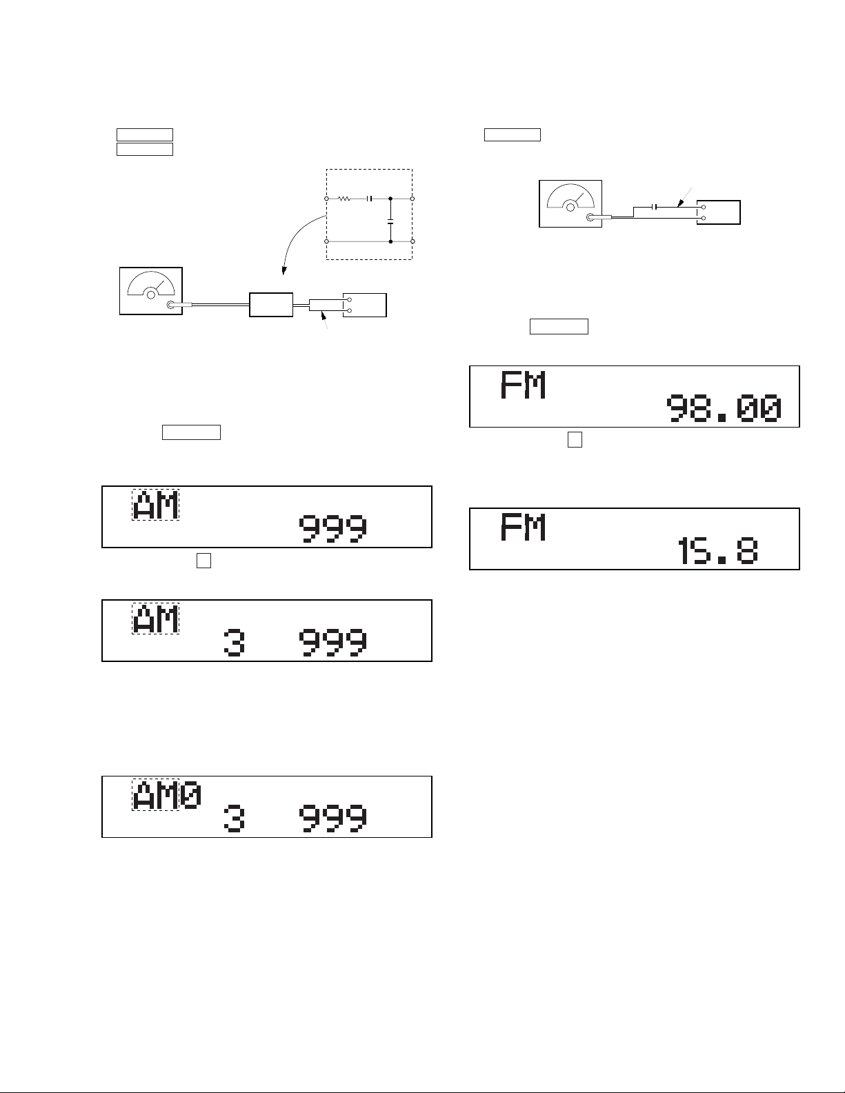
AM (MW) Auto Scan/Stop Level Adjustment
(
)
Setting:
SOURCE button (MDX-C670) : AM
SOURCE button (MDX-C670RDS): MW
30
Ω
15 pF
65 pF
AM RF signal
generator
AM dummy antenna
(50 Ω)
Carrier frequency : 999 kHz
30% amplitude
modulation by
1 kHz signal
Output level : 33 dB
44.7 µV
set
antenna
terminal
Procedure:
1. Set to the test mode. (See page 12.)
2. Push the SOURCE button and set to AM (MDX-C670) or MW
(MDX-C670RDS).
Display
*1
TP
REG
SHUF1
RDS S-Meter Adjustment (MDX-C670RDS)
Setting:
SOURCE button: FM
FM RF signal
generator
0.01µF
Carrier frequency : 98.0 MHz
Output level : 35 dB (56.2
Mode : mono
Modulation : no modulation
antenna
terminal
µ
V)
set
Procedure:
1. Set to the test mode. (See page 12.)
2. Push the SOURCE button and set to FM.
Display
REG
SHUF1
3. Push the preset 10 button.
4. Adjust RV1 on MAIN board so that the display indication is
“15.8”.
Display
REG
SHUF1
3. Push the preset 3 button.
Display
*1
TP
REG
SHUF1
4. Adjust with the volume R V1 on TU1 so that the “AM” or “MW”
indication turns to “AM0” or “MW0” indication on the display
window.
But, in case of already indicated “AM0” or “MW0”, turn the
RV1 so that put out light “0” indication and adjustment.
Display
*1
TP
REG
SHUF1
*1 : MDX-C670RDS is indicates “MW”.
Adjustment Location: See page 14.
Specification: Display indication : 15.6 to 16.4
Adjustment Location: See page 14.
– 13 –
Adjustment Location:
– SET UPPER VIEW –
TU1
RV1 AM (MW) AUTO SCAN/STOP LEVEL Adjustment
RV2 FM AUTO SCAN/STOP LEVEL Adjustment
RV4 FM STEREO SEPARATION Adjustment
RV1 RDS S-METER Adjustment
– 14 –
 Loading...