

Page 1
MDR-Z7
SERVICE MANUAL
Ver. 1.0 2014.09
SPECIFICATIONS
Type Closed, dynamic (circum-aural)
Driver unit 70 mm, dome type (CCAW Voice Coil)
Power handling capacity 2,000 mW (IEC*)
Impedance 70 Ω at 1 kHz
Sensitivity 102 dB/mW
Frequency response 4 Hz - 100,000 Hz
Mass Approx. 335 g without cable
Supplied accessories
Headphone cable (Approx. 3 m, silver-coated OFC strands, gold-plated stereo mini
plug) (1)
Balanced-connection headphone cable (Approx. 2 m, silver-coated OFC strands,
3-pole mini plug × 2) (1)
Gold-plated unimatch plug adaptor (stereo phone plug stereo mini jack) (1)
Operating Instructions (1)
* IEC = International Electrotechnical Commission
Design and specications are subject to change without notice.
US Model
Canadian Model
AEP Model
UK Model
E Model
Australian Model
Chinese Model
9-896-052-01
2014I33-1
2014.09
©
STEREO HEADPHONES
Sony Corporation
Published by Sony Techno Create Corporation
Page 2
MDR-Z7
SECTION 1
SERVICING NOTES
The SERVICING NOTES contains important information for servicing. Be sure to read this section before repairing the unit.
DESTINATION ABBREVIATIONS
The following abbreviations for model destinations are used in this
service manual.
• Abbreviations
AUS : Australian model
CH : Chinese model
CND : Canadian model
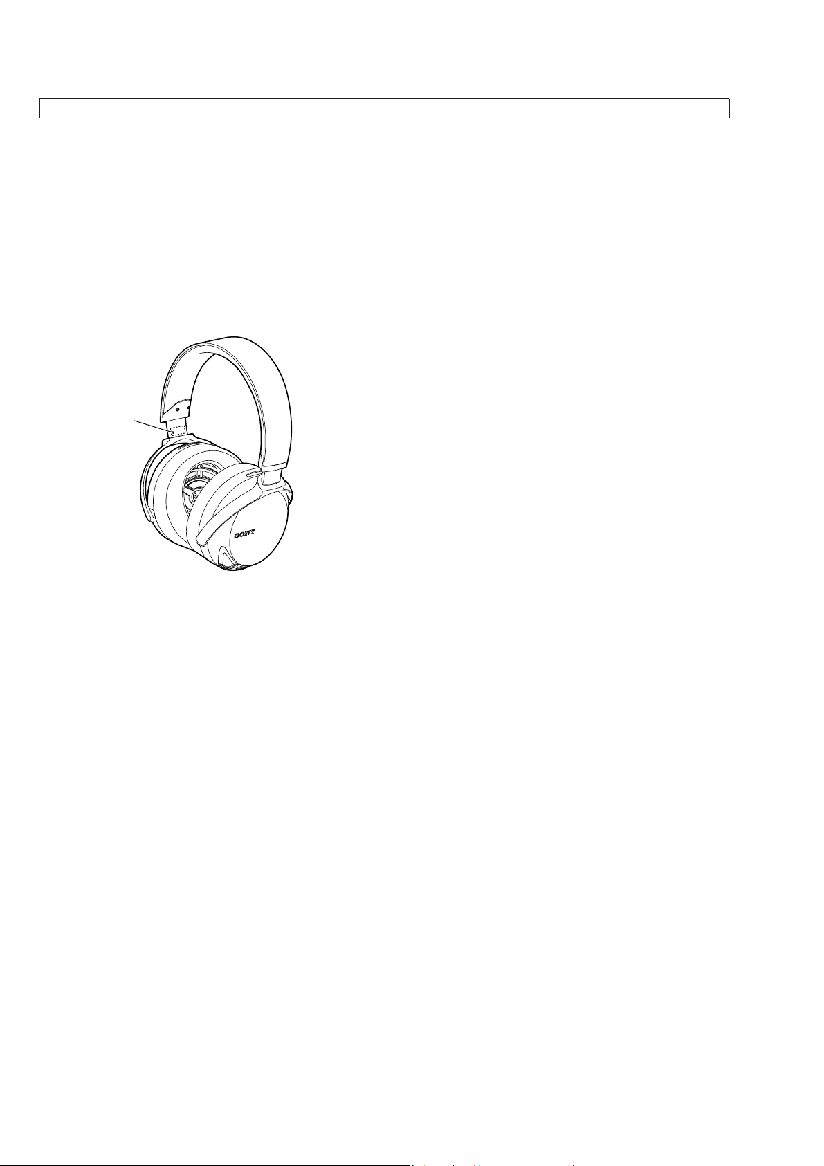
NOTE OF REPLACING THE HEAD BAND ASSY
A serial number is marked on the unit’s head band arm.
Therefore, when the head band assy is replaced, the serial number
changes.
serial number
– L-ch –
– R-ch –
2
Page 3
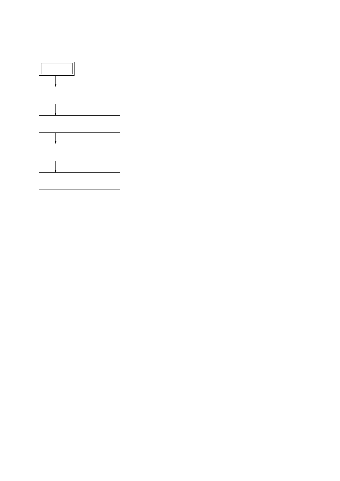
DISASSEMBLY
• This set can be disassembled in the order shown below.
2-1. DISASSEMBLY FLOW
MDR-Z7
SECTION 2
SET
2-2. EAR PAD, EAR PAD HOLDER
(Page 4)
2-3. HOUSING BLOCK
(Page 5)
2-4. FRONT PLATE ASSY
(Page 5)
2-5. HOUSING ASSY, HANGER
(Page 6)
Note: Please detach the CABLE WITH PLUG beforehand.
3
Page 4

MDR-Z7
Note: Follow the disassembly procedure in the numerical order given.
2-2. EAR PAD, EAR PAD HOLDER
Note 1: L-ch and R-ch can be similarly disassembled.
The illustration of R-ch is used for explanation.
When installing the ear pad block to the housing block,
Note 2:
align the ear pad block boss with the housing block ditch.
1 Turn over the ear pad.
5 ear pad
3 Remove the ear pad block
in the direction of the arrow.
hole
2 screw (P2)
ditch
ditch
housing block
boss
ear pad block
Turn in the direction of
the arrow until it stops.
Note 3:
4
When installing the ear pad, check the inside color.
– L-ch –– R-ch –
Inside color is [black].
Inside color is [red].
6 ear pad holder
4 Remove the protrusion
from the ear pad hole.
Page 5

2-3. HOUSING BLOCK
Note:L-ch and R-ch can be similarly disassembled.
The illustration of R-ch is used for explanation.
1 ornamental screw
(M1.7)
MDR-Z7
1 ornamental screw
(M1.7)
3 twist holder
5 housing block
2-4. FRONT PLATE ASSY
Note: L-ch and R-ch can be similarly disassembled.
The illustration of R-ch is used for explanation.
boss
2 Remove the front plate assy
in the direction of the arrow.
4 axis cushion
2 shaft stopper
:LUHVHWWLQJ
[red]
(marking side)
[bronze]
(no marking side)
Direction in which
to apply the solder.
boss
3 Remove the solder
[red]
3 Remove the solder
[blonze]
4 front plate assy
ditch
ditch
1 three screws
(P2)
1 three screws
(P2)
cable with jack
marking
front plate assy
5
Page 6

MDR-Z7
2-5. HOUSING ASSY, HANGER
Note 1: L-ch and R-ch can be similarly disassembled.
The illustration of R-ch is used for explanation.
6 hanger
$[LVFXVKLRQDQG+DQJHUKROGHUVHWWLQJ
Align the directions
of the slopes.
hanger
groove
axis cushion
5 axis cushion
3 housing holder
4 housing assy
2 two screws
(P2)
5 axis cushion
2 two screws
(P2)
3 housing holder
1 rear seal
Note 2:
affix the glossy surface to
the housing assy.
When installing the rear seal,
hanger holder
–KDQJHUERWWRPYLHZ–
6
Page 7

Note:
• -XX and -X mean standardized parts, so
they may have some difference from the
original one.
• Items marked “*” are not stocked since
they are seldom required for routine service. Some delay should be anticipated
when ordering these items.
3-1. HOUSING (R-ch) SECTION
• Front view
9
7
10
8
6
6
7
4
4
4
SECTION 3
EXPLODED VIEWS
• The mechanical parts with no reference
number in the exploded views are not supplied.
• Color Indication of Appearance Parts Example:
KNOB, BALANCE (WHITE) . . . (RED)
– R-ch –
7
4
Parts Color Cabinet’s Color
11
11
MDR-Z7
housing (L-ch), head band section
– L-ch –
4
HJ2
4
4
5
DR2
4
4
4
2
3
1
Ref. No. Part No. Description Remark Ref. No. Part No. Description Remark
1 4-541-036-01 PAD (R), EAR (R-ch)
2 4-541-034-01 HOLDER, EAR PAD
3 3-080-204-31 SCREW, TAPPING, P2
4 3-080-205-21 SCREW, TAPPING, P2
5 4-541-023-01 SEAL, REAR
6 4-541-025-01 HOLDER, HANGER
7 4-541-076-01 CUSHION, AXIS
8 4-541-013-01 HANGER (R) (R-ch)
9 4-540-997-01 HOLDER, TWIST
10 4-540-998-01 STOPPER, SHAFT
11 4-541-006-01 ORNAMENTAL SCREW M1.7 (TAPPING)
DR2 X-2590-515-1 PLATE (R) ASSY, FRONT (SV) (Including Driver)
(R-ch)
HJ2 X-2590-513-1 HOUSING (R) ASSY (SV)
(Including Cable with jack) (R-ch)
7
Page 8

MDR-Z7
3-2. HOUSING (L-ch), HEAD BAND SECTION
• Rear view
– L-ch –
61
HB1
A serial number is marked on the unit’s head
Note:
band arm. Therefore, when the head band assy
is replaced, the serial number changes.
HJ1
58
59
57
57
56
55
54
54
60
56
61
DR1
– R-ch –
57
54
54
54
54
54
54
54
54
52
53
51
Ref. No. Part No. Description Remark Ref. No. Part No. Description Remark
51 4-541-035-01 PAD (L), EAR (L-ch)
52 4-541-034-01 HOLDER, EAR PAD
53 3-080-204-31 SCREW, TAPPING, P2
54 3-080-205-21 SCREW, TAPPING, P2
55 4-541-023-01 SEAL, REAR
56 4-541-025-01 HOLDER, HANGER
57 4-541-076-01 CUSHION, AXIS
58 4-541-012-01 HANGER (L) (L-ch)
59 4-540-997-01 HOLDER, TWIST
60 4-540-998-01 STOPPER, SHAFT
61 4-541-006-01 ORNAMENTAL SCREW M1.7 (TAPPING)
DR1 X-2590-514-1 PLATE (L) ASSY, FRONT (SV) (Including Driver)
(L-ch)
HB1 X-2590-510-1 BAND ASSY, HEAD (SV) (US, CND, E, AUS, CH)
(See Note)
HB1 X-2590-511-1 BAND ASSY, HEAD (SV) (AEP, UK) (See Note)
HJ1 X-2590-512-1 HOUSING (L) ASSY (SV) (Including Cable with jack)
(L-ch)
8
Page 9

SECTION 4
ACCESSORIES
Ref. No. Part No. Description Remark
4-538-073-11 MANUAL, INSTRUCTION
(ENGLISH, FRENCH, SPANISH) (US, CND)
4-538-073-21 MANUAL, INSTRUCTION
(ENGLISH, FRENCH, GERMAN, SPANISH,
DUTCH, ITALIAN, PORTUGUESE, POLISH,
GREEK, CZECH, HUNGARIAN, BULGARIAN,
SLOVAK, SLOVENIAN, ROMANIAN) (AEP, UK)
4-538-073-31 MANUAL, INSTRUCTION
(ENGLISH, RUSSIAN, TRADITIONAL CHINESE,
KOREAN, UKRAINIAN) (E, AUS)
4-538-073-41 MANUAL, INSTRUCTION (SIMPLIFIED CHINESE)
(CH)
MDR-Z7
501 1-566-410-41 ADAPTOR, PLUG (Gold-plated unimatch plug
502 1-848-516-11 CABLE WITH PLUG (Headphone cable
502 1-848-516-21 CABLE WITH PLUG (Headphone cable
503 1-848-517-11 CABLE WITH PLUG (BALANCED)
503 1-848-517-21 CABLE WITH PLUG (BALANCED)
501
Gold-plated unimatch plug adaptor
(stereo phone plug y stereo mini jack)
502
Headphone cable
(Approx. 3 m, silver-coated OFC strands, gold-plated stereo mini plug)
adaptor (stereo phone plug y stereo mini jack))
(Approx. 3 m, silver-coated OFC strands,
gold-plated stereo mini plug)) (AEP, UK)
(Approx. 3 m, silver-coated OFC strands,
gold-plated stereo mini plug))
(US, CND, E, AUS, CH)
(Balanced-connection headphone cable
(Approx. 2 m, silver-coated OFC strands,
3-pole mini plug x 2)) (AEP, UK)
(Balanced-connection headphone cable
(Approx. 2 m, silver-coated OFC strands,
3-pole mini plug x 2)) (US, CND, E, AUS, CH)
503
Balanced-connection headphone cable
(Approx. 2 m, silver-coated OFC strands, 3-pole mini plug × 2)
9
Page 10

MDR-Z7
REVISION HISTORY
Ver. Date Description of Revision
1.0 2014.09 New
 Loading...