

Sony KP-43T70, KP-46C70, KP-48S70, KP-48S72, KP-53S70 Service Manual
...
SERVICE MANUAL
RA-3
CHASSIS
MODEL
COMMANDER DEST. CHASSIS NO.
KP-43T70 RM-Y906 US SCC-P14GA
KP-43T70 RM-Y906 Canadian SCC-P14GA
KP-46C70 RM-Y906 US SCC-P14JA
KP-46C70 RM-Y906 Canadian SCC-P14JA
KP-48S70 RM-Y906 US SCC-P14HA
KP-48S70 RM-Y906 Canadian SCC-P14HA
KP-48S72 RM-Y906 US SCC-P14KA
CORRECTION -1
Subject : Correction of set-up adjustments
File this correction with the service manual.
MODEL
COMMANDER DEST. CHASSIS NO.
KP-48S72 RM-Y906 Canadian SCC-P14KA
KP-53N74 RM-Y906 US SCC-P14EA
KP-53N74 RM-Y906 Canadian SCC-P14EA
KP-53S70 RM-Y906 US SCC-P14DA
KP-53S70 RM-Y906 Canadian SCC-P14DA
KP-61S70 RM-Y906 US SCC-P14FA
KP-61S70 RM-Y906 Canadian SCC-P14FA
TABLE OF CONTENTS
Section Title Page
–––––– –––– ––––
3. SET-UP ADJUSTMENTS
3-1. Screen Voltage Adjustment (Coarse Adjustment) ................................. 2
3-2. Screen (G2) Adjustment (Fine Adjustment) ......................................... 2
3-3. Deflection York Tilt Adjustment ........................................................... 2
3-4. Focus Lens Adjustment ......................................................................... 2
3-5. Focus VR Adjustment ........................................................................... 3
3-6. 2-Pole Magnet Adjustment (Green, Red) ............................................. 3
3-7. 4-Pole Magnet Adjustment ................................................................... 3
3-8. Defocus Adjustment (Blue) .................................................................. 3
3-9. Electrical Adjustment by Remote Commander .................................... 4
3-10. Registration Adjustment (PJE) .............................................................. 9
3-11. Auto Registration Error Code List ..................................................... 12
Please file according to model size. ..........
Please file according to model size. ..........
Please file according to model size. ..........
43
48 53 6146
KP-43T70/46C70/48S70/
48S72/53N74/53S70/61S70
RM-Y906
SECTION 3
SET-UP ADJUSTMENTS
3-1. SCREEN VOLTAGE ADJUSTMENT
(COARSE ADJUSTMENT)
1. Receive the Monoscope signal.
2. Set 50% BRIGHTNESS and minimum PICTURE.
3. Turn the red VR on the FOCUS block all the way to the left
and then gradually turn it to the right until the point where you
can see the retrace line.
4. Next gradually turn it to the left to the position where the
retrace line disappears.
R G B
SCREEN
R G B
FOCUS
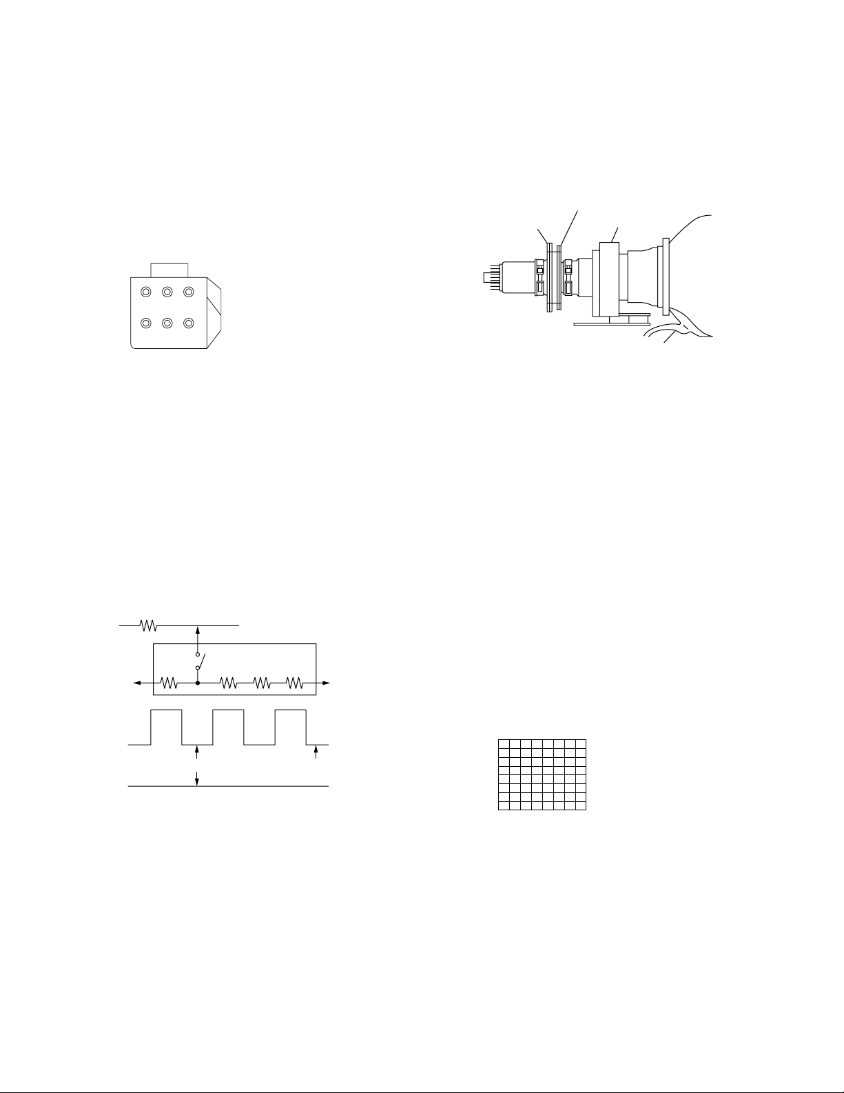
FOCUS block
Fig. 3-1
3-2. SCREEN (G2) ADJUSTMENT
(FINE ADJUSTMENT)
Fine Mode is recommended to set screen controls to their optimal
condition. It is necessary to build the simple jig, illustrated below,
using 3-watt resistors. Please note, that if the proper voltage is not
obtained with their listed values, resistors, then please increase or
decrease one of the values in the resistor network to obtain the
correct voltage.
1. Select VIDEO1 mode without signals.
2. Connect G2 JIG.
3. SW on JIG.
4. Connect an oscilloscope to the TP701(KR), TP732(KG) and
TP761(KB) of CR board, CG board and CB board.
5. Adjust R, G and B screen voltage to 170-173V with screen
VR on the Focus block.
K
G2 JIG
3.3k 5.6k 5.6k 5.6k
210V GND
SW
the mode Cover the both green and red picture lenses with the
lens caps is aligned the same as was done for green.
Note: Instead of items 3 and 6, you can cut off the unnecessary
color beams by controlling the service mode VPNT 28 RON,
29 GON, and 30 BON.
4-pole magnet
2-pole magnet
Fig. 3-3
Deflection yoke
Anode cap
3-4. FOCUS LENS ADJUSTMENT
In this adjustment, use the remote commander in the
service mode.
For details of the usage of the service mode and the remote
commander, please refer the item 3-9. ELECTRICAL
ADJUSTMENT BY REMOTE COMMANDER.
1. Loosen the lens screw.
2. Set to the service mode.
3. Receive the all-white signal.
4. Cover the both red and blue picture lenses with the lens caps
to show only the green color.
5. Set to PJE, and press 6 to display the test signal (crosshatch)“
on the screen.
6. Turn the green lens to adjust to the optimum focus point with
the test signal.
7. Tighten the lens screw.
8. Cover the both green and blue picture lenses with the lens caps
to show only the red color.
9. Set to PJE, and press 6 to display the test signal (crosshatch)“
on the screen.
10. Adjust red CRT lens just the same as green.
11. Cover the both green and red picture lenses with the lens caps
to show only the blue color.
175 ± 2V
GND
pedestal level
Fig. 3-2
3-3. DEFLECTION YOKE TILT ADJUSTMENT
1. Receive the Monoscope signal.
2. Set in service mode.
3. Cover the both red and blue picture lenses with the lens caps
to show only the green color.
4. Loosen the deflection yoke set screw and align the tilt of the
Deflection Yoke so that the bars at the center of the
monoscope pattern are horizontal.
5. After aligning the deflection yoke, fasten it securely to the
funnel-shaped portion (neck) of the CRT.
6. The tilt of the deflection yoke for red is aligned in the mode
Cover the both green and blue picture lenses with the lens caps
and the tilt of the deflection yoke for blue is aligned with in
Test signal
Fig. 3-4
12. Set to PJE, and press 6 to display the test signal (crosshatch)“
on the screen.
13. Adjust blue CRT lens just the same as green.
14. After adjusting the items 3-5. Focus VR Adjustment, 3-6. 2Pole Magnet Adjustment and 3-7. 4-Pole Magnet Adjustment,
adjust again to the optimum focus point.
*: Every time you press 6, the test signal changes to
“crosshatch+video signal” - “dots+video signal” -
“crosshach(black)” - “dots(black)” - off.
Note: Instead of items 4, 8 and 11, you can cut off the unnecessary
color beams by controlling the service mode VPNT 28 RON,
29 GON, and 30 BON.
– 2 –
KP-43T70/46C70/48S70/
/
x
y
x : y = 1:1.5 (BIue)
x : y = 1:1 (Green, Red)
Use the center dot
48S72/53N74/53S70/61S70
RM-Y906
3-5. FOCUS VR ADJUSTMENT
1. Set to the service mode.
2. Receive the all-white signal.
3. Cover the both red and blue picture lenses with the lens caps
to show only the green color.
4. Set to PJE, and press 6 to display the test signal (crosshatch)
on the screen.
5. Turn the green focus VR on the focus block to adjust to the
optimum focus point with the test signal.
6. Cover the both green and blue picture lenses with the lens caps
to show only the red color.
7. Set to PJE, and press 6 to display the test signal (crosshatch)
on the screen.
8. Turn the red focus VR on the focus block to adjust to the
optimum focus point with the test signal.
9. Cover the both green and red picture lenses with the lens caps
to show only the blue color.
10. Set to PJE, and press 6 to display the test signal (crosshatch)
on the screen.
11. Turn the blue focus VR on the focus block to adjust to the
optimum focus point with the test signal.
12. After adjusting the items 3-4. Focus Lens Adjustment, 3-6. 2Pole Magnet Adjustment and 3-7. 4-Pole Magnet Adjustment,
adjust again to the optimum focus point.
Note: Instead of items 3, 6 and 9, you can cut off the unnecessary
color beams by controlling the service mode VPNT 28 RON,
29 GON, and 30 BON.
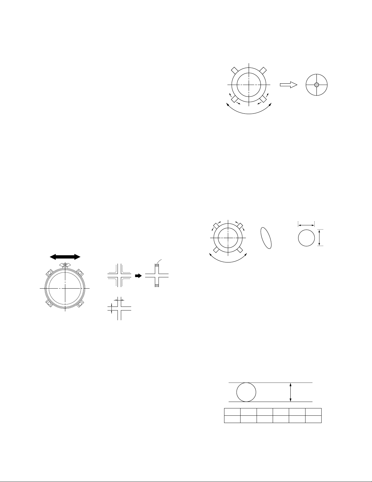
Use the center dot
Fig. 3-7
3-7. 4-POLE MAGNET ADJUSTMENT
1. Receive the Dot signal.
2. Set in service mode.
3. Cover the both red and blue picture lenses with the lens caps
to show only the green color.
4. Turn the green focus VR on the focus block to the left and set
to underfocus to enlarge the spot.
5. Now align the 4-Pole Magnet so that the enlarged spot
becomes a perfect circle for green and red.
6. Perform the same alignment for blue.
Scanning line visible.
A
Minimize both A and B.
Lens
B
Center of crosshatch
Fig. 3-6Fig. 3-5
3-6. 2-POLE MAGNET ADJUSTMENT
(GREEN,RED)
1. Receive the Dot signal.
2. Set in service mode.
3. Cover the both red and blue picture lenses with the lens caps
to show only the green color.
4. Turn the green focus VR on the focus block to the right and
set to overfocus to enlarge the spot.
5. Now align the 2-Pole Magnet so that the enlarged spot is in
the center of the Just Focus spot.
6. Align the green focus VR and set for just (precise) focus.
7. Perform the same alignment for red.
Fig. 3-8
3-8. DEFOCUS ADJUSTMENT (BLUE)
Note: Please adjust the blue dot to be slightly larger than red and
green dots. This adjustment provides a more pleasing picture
to the customer.
1. Select the video menu and set the mode to “VIVID” mode.
2. Set to the service mode.
3. Change TV mode to the video input mode.
4. Set to PJE, and press 6 to display the test signal (dots) on the
screen.
5. Turn the blue focus VR on the focus block to adjust to the
diameter of the dots as shown in the figure below.
[Focus adjustment point]
Lmm Max
Inch
L
43"
6
46"
6.5
Fig. 3-9
48"
7
53"861"
9
– 3 –
KP-43T70/46C70/48S70/
atad
2
5
8
0
1
4
7
3
6
9
ENTER
JUMP
GUIDE
INDEX
RESET
MENU
POWER
MUTING
FREEZE
AUDIO
ANT
TV/VIDEO
DISPLAYMTS/SAP
CC
PICTURE
MODE
POSITION ACTIVE
SWAP PIP
TV/VTR
SYSTEM
OFF
DVD/VTR SAT/CABLE
TV
DVD/
VTR
SAT/
CABLE
FUNCTION
SLEEP
m
N
M
xz
X
TV
48S72/53N74/53S70/61S70
RM-Y906
3-9. ELECTRICAL ADJUSTMENT BY REMOTE
COMMANDER
By using Remote Commander (RM-Y906),all circuit adjustments
can be made.
NOTE : Test Equipment Required.
1. Pattern Generator (with component outputs)
2. Frequency counter
3. Digital multimeter
4. Audio oscillator
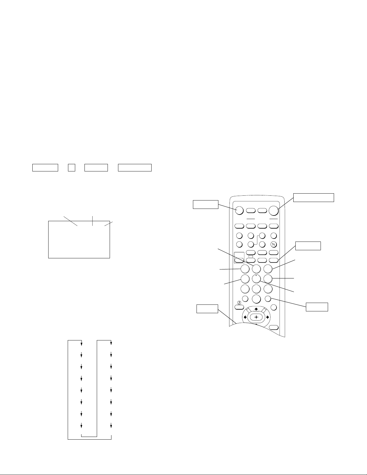
1. METHOD OF SETTING THE SERVICE ADJUSTMENT MODE
SERVICE MODE PROCEDURE
1. Standby mode. (Power off)
2. DISPLAY n 5 n VOL (+) n TV POWER
on the Remote Commander.
(Press each button within a second.)
SERVICE MODE ADJUSTMENT
Category Adjustment item
DATA
SERVICE VPNT VPOS 031
000000 00
7. If you want to recover the latest values press - then [ENTER] to
read the memory.
8. Press [MUTING] then [ENTER] to write into memory.
9. Turn power off.
Note: Press 8 then [ENTER] on the Remote Commander to initialize
or turn set off and on to exit.
2. MEMORY WRITE CONFIRMATION METHOD
1. After adjustment, remove the plug from AC outlet, and then
replace the plug in AC outlet again.
2. Turn the power switch ON and set to Service Mode.
3. Call the adjusted items again and confirm they were adjusted.
3. ADJUSTING BUTTONS AND INDICATOR
TV POWER ON
MUTING
(SCREEN DISPLAY)
3. The SCREEN displays the item being adjusted.
4. Press 1 or 4 on the Remote Commander to select the
adjustment item.
5. Press 3 or 6 on the Remote Commander to change the data.
6. Press 2 or 5 on the Remote Commander to select the
category.
Every time you press 2(Category up), Service mode changes
in the order as shown below.
VPNT
VPNV
VPNS
PJE
3DCM
TONE
DSP
MC
SC
IC
PP
DAC
PI
ID
CCD
OP
Category up
Adjustment item up
Adjustment item down
VOL (+)
RM-Y906
Note : When the PJE mode is activated, which displays an
internally generated signal, several buttons on the remote
commander will have different functions than listed
above. Therefore, when in the PJE mode, refer to page 9
for button functions.
DISPLAY
Data up
Data down
Category down
ENTER
– 4 –
 Loading...