

Page 1

4-081-143-12(1)
Projection TV
© 2001 Sony Corporation
Operating Instructions
Operating Instructions
KP-43HT20
KP-53HS20
KP-53HS30
KP-61HS20
KP-61HS30
Page 2
WARNING
To prevent fire or shock hazard, do not
expose the projection TV to rain or
moisture.
CAUTION
RISK OF ELECTRIC SHOCK
DO NOT OPEN
ATTENTION
RISQUE DE CHOC ELECTRIQUE,
NE PAS OUVRIR
PRECAUCION
RIESGO DE CHOQUE ELECTRICO
NO ABRIR
CAUTION : TO REDUCE THE RISK OF ELECTRIC SHOCK,
DO NOT REMOVE COVER (OR BACK).
NO USER-SERVICEABLE PARTS INSIDE.
REFER SERVICING TO QUALIFIED SERVICE PERSONNEL.
This symbol is intended to alert the user to the
presence of uninsulated “danger ous voltage”
within the product’s enclosure that may be of
sufficient magnitude to constitute a risk of
electric shock to persons.
This symbol is intended to alert the user to the
presence of impor tant operating and
maintenance (servicing) instructions in the
literature accompanying the appliance.
CAUTION
To prevent electric shock, do not use thi s polarized AC
plug with an extension cord, receptacle or other outl et
unless the blades can be fully inserted to prevent blade
exposure.
CAUTION
When using TV games, computers, and similar
products with your projection TV, or viewing a
TV station whose logo always stays on the
screen, keep the brightness and contrast
functions at low settings. If a fixed (non-moving)
pattern such as a station logo is left on the screen
for long periods of time, especially at a high
brightness or contrast setting, the image can be
permanently imprinted onto the screen. These
types of imprints are not covered by your
warranty.
Note on Caption Vision
This television receiver provides display of television
closed captio ning in a cco rdan ce with §1 5. 119 of the F CC
rules.
Note to CATV system installer
This reminder is provided to call the CATV system
installer’s attention to Article 820-40 of the NEC that
provides guidelin es for proper grounding and, in
particular, specifies that the cable ground shall be
connected to the grounding system of the building, as
close to the point of cable entry as practical.
Use of this television receiver for other than private
viewing of programs broa dcast on UHF, VHF,
transmitted by cable companies or satellite for the use of
the general public may require authorization from the
broadcaster/cable company and/or program owner.
NOTIFICATION
This equipment has been tested and found to comply with
the limits for a Class B digital device pursuant to Part 15
of the FCC Rules. These limits are designed to provide
reasonable protection against harmful interference in a
residential installation. This equipment generates, uses,
and can radiate radio frequency energy and, if not
installed and used in accordance with the instructions,
may cause harmful interference with radio
communications. However, there is no guarantee that
interference will not occur in a particular installation. If
this equipment does cause harmful interference to radio
or television reception, which can be determined by
turning the equipment off and on, the user is encouraged
to try to correct the interference by one or more of the
following measures:
❑ Reorient or relocate the receiving antennas.
❑ Increase the separation between the equipment and
receiver .
❑ Connect the equipment into an outlet on a circuit
different from that to which the receiver is
connected.
❑ Consult the dealer or an experienced radio/TV
technician for help.
You are cautioned that any ch anges or
modifications not expressly approved in
this manual could void your warranty and
your authority to operate this equipment.
This document is for the remote control RM-Y908.
MODELS: KP-43HT20, KP-53HS20, KP-53HS30,
KP-61HS20, KP-61HS30
Please keep this notice with the instruction manual.
2
Page 3

Safety
❑ Operate the projection TV only on 120 V AC.
❑ The plug is designed, for safety purposes, to fit into
the wall outlet only one way. If you are unable to
insert the plug fully into the outlet, contact your
dealer.
❑ If any liquid or solid object should fall inside the
cabinet, unplug the projection TV immediately and
have it checked by qualified service personnel
before operating it further.
❑ If you will not be using the pr ojection T V for se veral
days, disconne ct the po w er by pulling the plu g itself.
Never pull on the cord.
For details concerning safety precautions, see
“Important Safeguards” on page 4.
Installing
❑ To prevent intern al heat buildup, do not block the
ventilation openings.
❑ Do not install the projection TV in a hot or humid
place, or in a place subject to excessive dust or
mechanical vibration.
❑ Avoid operating the projection TV at temperature
below 5°C (41°F).
❑ If the projection TV is transported directly from a
cold to a warm location, or if the room temperature
changes suddenly, the picture may be blurred or
show poor color. In this case, please wait a few hours
to let the moisture evaporate before turning on the
projection TV.
❑ To obtain the best picture, do not expose the screen
to direct illumination or direct sunlight. It is
recommended to use spot lighting directed down
from the ceiling or to cover the windows that face
the screen with opaque drapery. It is desirable to
install the projection TV in a room where the floor
and walls are not of a reflective material.
Note on convergence adjustment
Before you use your projection TV, make sure to adjust
convergence. For details, see “Adjusting the Con verg ence
Automatically – FLASH FOCUS™ –” on page 33.
TruSurround is a trademark of
SRS Labs, Inc. SRS and the SRS
symbol are registered trademarks
of SRS Labs, Inc. in the United States and selected
foreign countries. SRS and TruSurround are incorporated
under license from SRS Labs, Inc. and is protected under
United States Patent Nos. 4,748,669 and 4, 841, 572 with
numerous additional issued and pending foreign patents.
Purchase of this product does not convey the right to sell
recordings made wi th the TruSurround technology.
BBE and BBE Symbol are trademarks of B BE Sound,
Inc. and are licensed by BBE Sound, Inc. under U.S.
Patent No. 4,638,258 and 4,482,866.
ATTENTION
Pour prévenir les chocs électriques, ne pas utiliser cette
fiche polarisée avec un prolongateur, une prise de courant
ou une autre sortie de courant, sauf si les lames peuvent
tre inserées à fond sans en laisser aucune partie à
decouvert.
Owner’s Record
The model and serial numbers are locat ed at the rear of
the projection TV, below the Sony logo, on the sticker,
and also on the TV box (white label). Record these
numbers in the spaces provided below. Refer to them
whenever you call upon your Sony dealer regarding this
product.
Model No.
Serial No.
ENERGY STAR
As an ENERGY STAR®
Partner, Sony Corporation has
determined that this product
meets the ENERGY STAR
guidelines for energy efficiency.
®
is a U.S. registered mark.
®
3
Page 4
Important Safeguards
For your protection, please read these instructions
completely, and keep this manual for future reference.
Carefully observe and comply with all w arnings, cautions
and instructions placed on the set or described in the
operating instructions or service manual.
WARNING
To guard against injury, the following basic safety
precautions should be observed in the installation, use
and servicing of the set.
Use
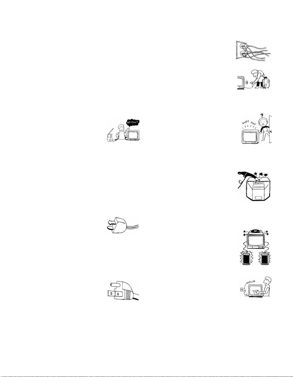
Power Sources
This set should be operated only from
the type of power source indicated on
the serial/model plate. If you are not sure
of the type of electrical power supplied
to your home, consult your dealer or
local power company. For those sets designed to operate
from battery power, refer to the operating instructions.
Grounding or P olarization
This set is equipped with a polarized AC power cord plug
(a plug having one blade wider than the other), or with a
three-wire grounding type plug (a plug having a third pin
for grounding). Follow the instructions below:
For the set with a polarized AC power cord
plug
This plug will fit into the power outlet
only one way. This is a safety feature. If
you are unable to insert the plug fully
into the outlet, try reversing the plug. If
the plug still fails to fit, contact your electric ian to ha ve a
suitable outlet installed. Do not defeat the safety purpose
of the polarized pl ug by forcing it in.
Overloading
Do not overload wall outlets, extension
cords or convenience receptacles
beyond their capacity, since this can
result in fire or e lectric shock.
Always turn the set off when it is not
being used. When the set is left
unattended and unused for long
periods of time, un plug it from the
wall outlet as a precaution against the
possibility of an internal malfunction that could create a
fire hazard.
If a snapping or popping sound from a TV
set is continuous or frequent while the TV
is operating, unplug the TV and c onsult
your dealer or service technici an. It is
normal for some TV sets to make
occasional snappin g or popping sounds,
particularly when being turned on or off.
Object and Liquid Entry
Never push objects of any kind into the
set through the cabinet slots as they may
touch dangerous voltage points or short
out parts that could result in a fire or
electric shock. Never spill liquid of any
kind on the set.
Attachments
Do not use attachments not
recommended by the manufacturer, as
they may cause hazards.
Alternate Warning for the set with a threewire grounding type AC plug
This plug will only fit into a groundingtype power outlet. This is a safety
feature. If you are unable to insert the
plug into the outlet, contact your
electrician to have a suitable outlet
installed. Do not defeat the safety purpose of the
grounding plug.
4
Cleaning
Clean the cabinet of the projection TV
with a dry soft cloth. To remove dust
from the screen, wipe it gent ly with a soft
cloth. Stubborn stains may be removed
with a cloth slightly dampened with
solution of mild soap and warm water. Never use strong
solvents such as thinner or benzine for cleaning.
If the picture becomes dark after using the projection TV
for a long period of time, it may be necessary to clean th e
inside of the projection TV. Consult qualified service
personnel.
Page 5
Installation
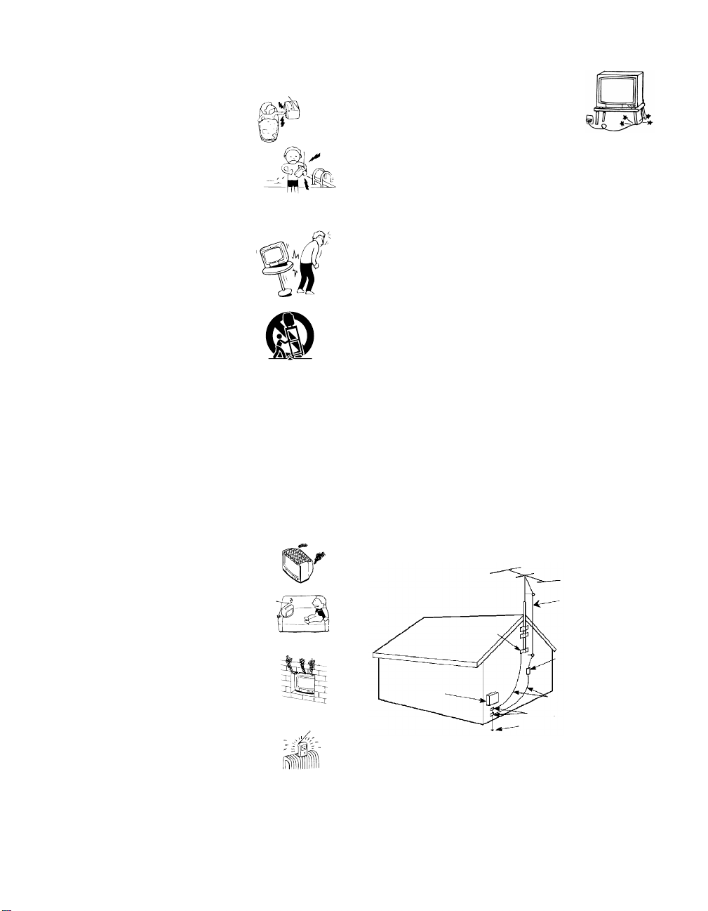
Water and Moisture
Do not use power-line operated sets
near water — for example, near a
bathtub, washbowl, kitchen sink, or
laundry tub, in a wet basement, or
near a swimm i n g pool, etc.
Accessories
Do not place the set on an unstable
cart, stand, table or shelf. The set
may fall, causing serious injury to a
child or an adu lt and se rious dam age
to the set. Use only a cart or stand
recommended by the manufacturer
for the specific model of projection
TV. An ap pliance and cart
combination shoul d be moved with
care. Quick stops, excessive force,
and uneven surfaces may cause the appliance and cart
combination to overturn.
Ventilation
The slots and openings i n the cabinet and in the back or
bottom are provided for necessary ventilation. To ensure
reliable operation of the set, and to protect it from
overheating, these slots and openings must never be
blocked or covered.
❑ Never cover the slots and openings
with a cloth or other materials.
Power-Cord Protection
Do not allow anything to rest on or roll
over the power cord, and do not place the
set where the power cord is subject to
wear or abuse.
Antennas
Outdoor Antenna Grounding
If an outdoor antenna is installed, follow the precautions
below. An outdoor antenna system should not be located
in the vicinity of overhead power lines or other electric
light or power circuits, or where it can come in contact
with such power lines or circuits.
WHEN INSTALLING AN OUTDOOR ANTENNA
SYSTEM, EXTREME CARE SHOULD BE TAKEN TO
KEEP FROM CONTACTING SUCH POWER LINES
OR CIRCUITS AS CONTACT WITH THEM IS
ALMOST INVARIABLY FATAL.
Be sure the antenna system is grounded so as to provide
some protection against voltage surges and bu ilt-up sta tic
charges.
Section 810 of the National Electrical Code (NEC) in
USA and Section 54 of the Canadian Electrical Code in
Canada provides information with respect to proper
grounding of the mast and supporting structure,
grounding of the lead-in wire to an antenna discharge
unit, size of groundi ng conductors, location of antenna
discharge unit, connect ion to grounding el ectrodes, and
requirements for the grounding elect rode.
Antenna Grounding According to the NEC
Refer to section 54 -300 of Canadian Electrical Code for
Antenna Ground in g.
❑ Never block the slots and openings by
placing the set on a bed, sofa, rug or
other similar surface.
❑ Never place the set in a confined
space, such as a bookcase or built-i n
cabinet, unless proper ventilat ion is
provided.
❑ Do not place the set near or over a
radiator or heat register, or where it is
exposed to direct sunlight.
Ground clamp
Electrical
service
equipment
NEC: National
Electrical Code
Antenna lead-in wire
Antenna lead-in wire
(NEC Section 810-20)
Grounding conductors
(NEC section 810-21)
Ground clamps
Power service grounding
electrode system (NEC Art
250 Part H)
5
Page 6
Lightning
For added protection for this television receiver during a
lightning storm , or when it is left unattended and unused
for long periods of time, unplug it from the wall outlet
and disconnect the antenna. This will prevent damage to
the receiver due to lightning and power-line surges.
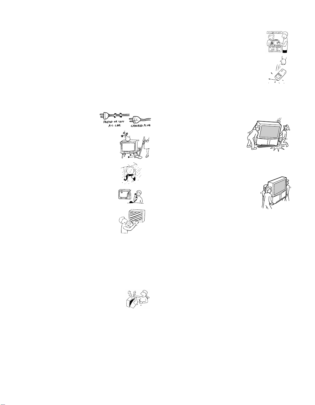
Service
Damage Requiring Service
Unplug the set from the wall outlet and refer servicing to
qualified service personnel under the following
conditions:
❑ When the power cord or
plug is damaged or frayed.
❑ If liquid has been spilled into
the set.
❑ If the set has been exposed
to rain or water.
❑ If the set has been subject to
excessive shock by being
dropped, or the cabinet has
been damaged.
❑ If the set does not operate
normally when following the
operating instructions.
Adjust only those controls
that are specified in the
operating instructions.
Improper adjustment of
other controls may result in
damage and will often
require extensive work by a
qualified technician to restore the set to normal
operation.
❑ When the set exhibits a distinct change in
performance, it indicates a need for servi ce.
Safety Check
Upon completion of any service or repairs
to the set, ask the service technician to
perform routine safety checks (as specified
by the manufacturer) to determine that the
set is in safe operating condition, and to so
certify. When the set reaches the end of its
useful life, improper disposal could result
in a picture tube implosion. Ask a qualified
service technician to dispose of the set.
For Safety
Be careful when moving
the projection TV
When you place the projection TV
in position, be careful not to drop it
on your foot or fingers.
Watch your footing while installing the projection TV.
Carry the projection TV in the
specified manner
If you carry the projection TV in a ma nner
other than the specified manner and
without the specifi ed number of persons, it
may drop and a serious injury may be
caused. Be sure to follow the instructions mentioned
below.
❑ Carry the projection TV with the specified number
of persons. (see page 10)
❑ Do not carry the projection TV holding the speaker
grill.
❑ Hold the projection TV tightly when carrying it.
Servicing
Do not attempt to service the set yourself
since opening the cabinet may expose you to
dangerous voltage or other hazards. Refer all
servicing to qualified service personnel.
Replacement Parts
When replacement parts are required, be sure the service
technician certifies in writing that he has used
replacement parts specif ied by the manufactu rer that ha ve
the same characteristics as the origi nal parts.
Unauthorized substitutions may result in fire , electric
shock or other hazards.
6
Page 7

Contents
Important Safeguards...............................................4
Introducing the Sony Projection TV
Presenting the Sony Projection TV..........................8
Using this manual........................ ... .........................9
Installing and Connecting the
Projection TV
Contents.................................................................10
Inserting Batteries into the Remote Control..........10
Carrying Your Projection TV ................................10
Installing the Projection TV................ .... ...............11
Connector Types....................................................12
Projection TV Controls and Connectors ................13
Basic Connections (Connecting Cable TV or
Antenna).........................................................16
Connecting a VCR and Cable................................19
Connecting a VCR and Cable Box ........................20
Connecting Two VCRs for Tape Editing ..............22
Connecting a Satellite Receiver.............................23
Connecting a Satellite Receiver with a VCR.........24
Connecting an Audio Receive r...................... ........25
Connecting a DVD Player with Component
Video Connectors..........................................26
Connecting a DVD Player with
A/V Connectors.............................................27
Connecting a Digital TV Receiver.........................28
Connecting a Camcorder .......................................29
Connecting an AV Receiver ..................................30
Using the CONTROL S Feature............................31
Setting Up the Projection TV Automatically.........32
Adjusting the Convergence Automatically
– FLASH FOCUS™ –...................................33
Using the Features
Using the Remote Control .....................................34
Watching the TV....................................................37
Watching the Digital TV .......................................39
Using Favorite Channels........................................40
Using Twin View™...............................................41
Using the Freeze Function.....................................44
Using Channel Index.............................................45
Using the Menus
Overview................................................................47
Using the Video Menu......................... ... .... ..........48
Using the Audio Menu.......... .... ... .........................50
Using the Channel Menu......................................52
Using the Parent Menu........................ ... .... ..........54
Using the Timer Menu................................ ..........62
Using the Setup Menu ................................ ... .......63
Other Information
Programming the Remote Control.........................65
Operating Other Components with Your
Projection TV Remote Control......................68
Troubleshooting.....................................................70
Specifications.........................................................73
7
Page 8

Introducing the Sony Projection TV
Presenting the Sony Projection TV
Thank you for purchasing the Sony Projection TV.
This manual is for models KP-43HT2 0, KP-53HS20, KP-53HS30, KP61HS20 and KP-61HS30.
Model KP-53HS30 is used for illustration purposes.
Features
Some of the features that you will enjoy with your new projection TV
include:
❑
Hi Scan 1080
digital TV formats. By using the VIDEO 5/6 IN jacks, you can connect
a DTV (digital television) receiver to view DTV programs.
❑
DRC™ Multi-Function: Unlike conventional line doublers, the DRC
feature doubles vertical and horizontal lines, resulting in four times the
density for quality sources such as DVD, Satellite and Digital
camcorder.
❑
CineMotion™: Using the 2-3 Pull-Down technology, the CineMotion
feature allows you to obtain a smooth picture movement when playing
back movies or other video sources on film.
❑
Twin View™: Using Multi-Image Driver (MID-X), Twin View allows
you to watch two programs side by side with the ability to zoom in on
one picture and listen to the program in the selected window. You can
watch pictures from two different sources (1080i, 720p, 480p or 480i)
simultaneously.
❑
16:9 Enhancement: Vertical Compression technology that maximizes
picture resolution on “anamorphic” or “enhanced for wide screen”
sources, including selected DVDs.
❑
Steady Sound™: Equalizes volume levels so there is consistent output
between programs and commercials.
❑
Parental Control: V-Chip technology allows parents to block
unsuitable programming for younger viewers.
❑
Component Video Inputs: Offers the best video quality for DVD
(480p, 480i) and Digital Set-top box (1080i, 720p, 480p, 480i)
connections.
❑
S-VIDEO Inputs: Provides a high-quality image for connected
equipment.
™
: Enables you to receiv e th e 108 0i, 7 20p, 480p and 480i
8
Page 9

Using this manual
Introducing the Sony Projection TV
❑
Favorite Channel Preview : Preview up to eight favorite channels
without leaving the current channel.
❑
Channel Inde x : Allows you to view and choose from twelve programs.
❑
Flash Focus
We recommend that you carefully review the contents of the following three
sections in the order shown to ensure that you fully un derst and the operat ion
of your new projection TV.
Installing and Connecting the Projection TV
1
This section guides you through your initial setup. It shows you how to
install your projection TV, to connect your new components and to connect
the antenna and cable.
Using the Features
2
This section shows you how to begin using your new projection TV. It also
shows you how to use your remote control functions.
Using the menus
3
™
: Allows you to adjust convergence automatically.
Introducing the Sony Projection TV
This section teaches you how to access on-screen menus and adjust your
projection TV settings.
Instructions in this manual are written for the remote control. Similar
controls are also found on the projection TV console.
9
Page 10
Installing and Connecting the Proj ection TV
Contents
The box contains your new projection TV, a remote control and two AA
batteries. No peripheral cables are included. If you intend to add additional
equipment to your projection TV, please check the hookup instructions for
your desired setup before you begin. You may need to purchase cables and/
or splitters to complete the hookup properly.
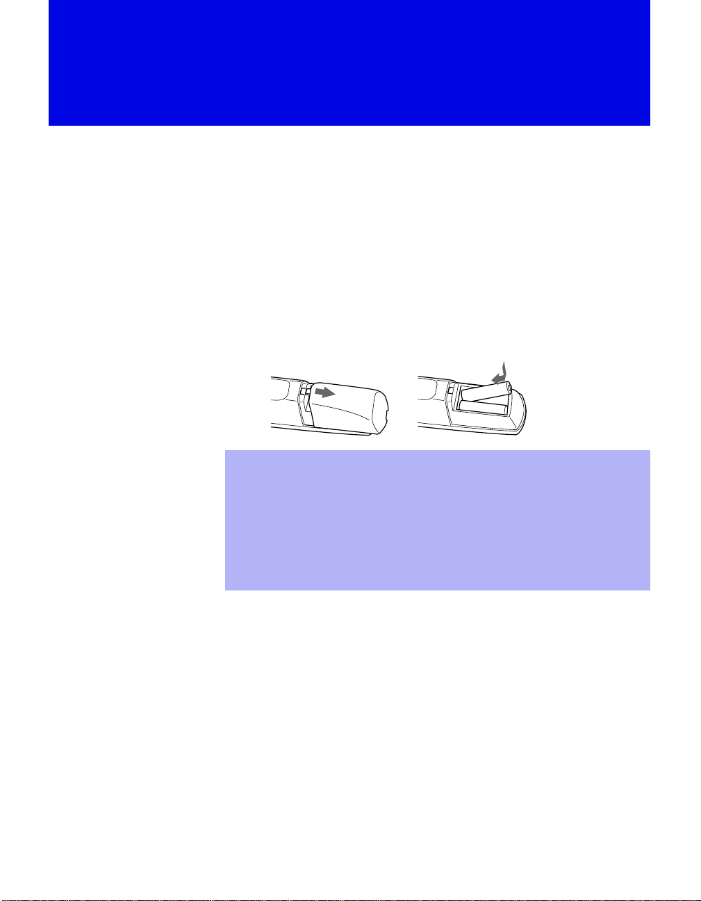
Inserting Batteries into the Remote Control
Insert two size AA (R6) batteries (supplied) by matching the + and – on the
batteries to the diagram inside the battery compartment.
e
E
e
E
Remove the batteries to avoid damage from possible battery leakage
✍
whenever you anticipate that the remote control will not be used for an
extended pe riod.
Handle the re mote control with care. Avoid dropping it, getting it wet, or
✍
placing it in direct sunlight, near a heater, or where the humidity is high.
Your remote control can be programmed to operate most video
✍
equipment. (See “Programming the Remote Control” on page 65.)
Carrying Your Projection TV
Carrying the projection TV requires three or more people.
The projection TV has been equipped with casters for easy movement on a
hard surface. (for KP-53HS20, KP-53HS30, KP-61HS20 and KP-61HS30
only)
Please move your projection TV using the casters.
10
Page 11
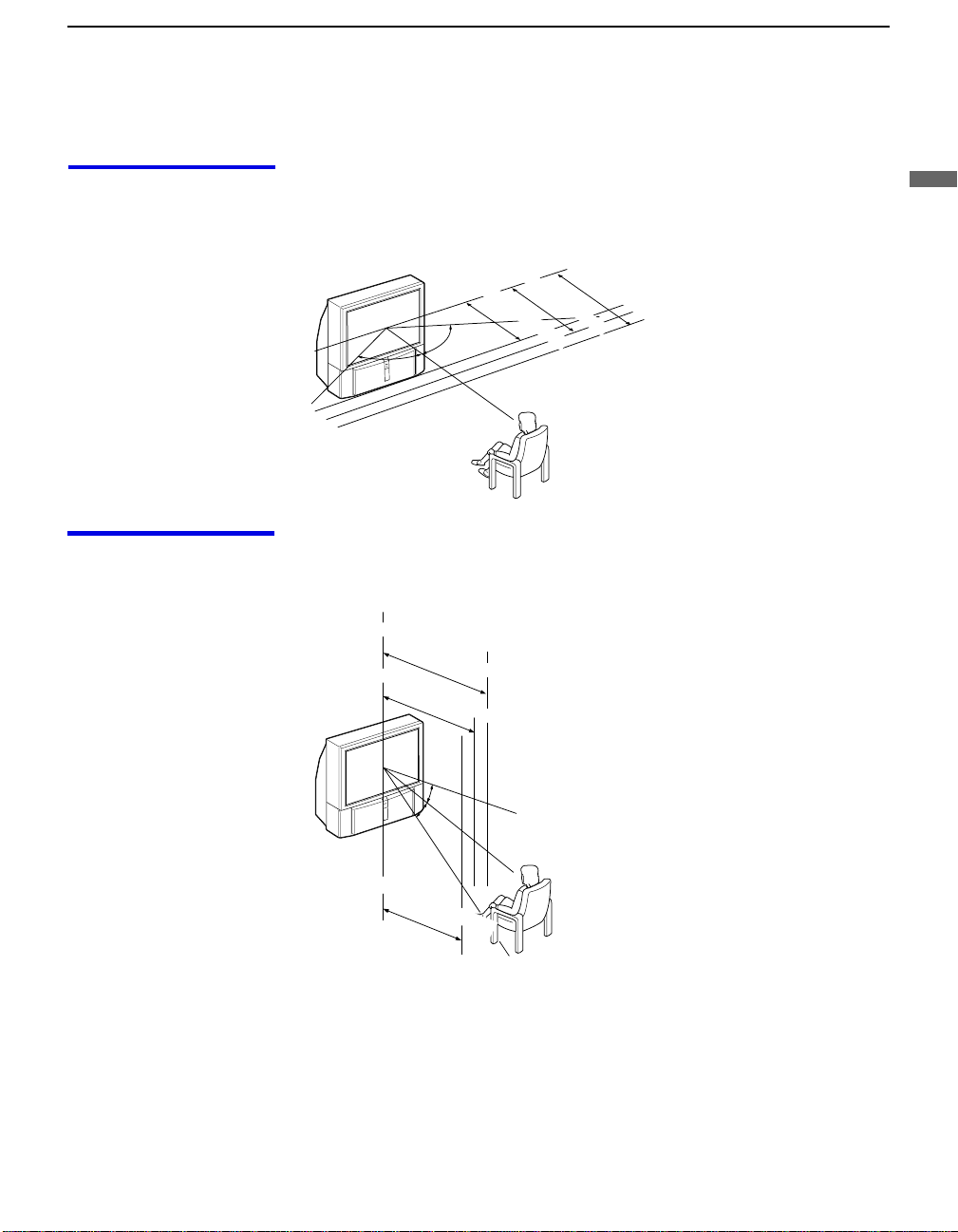
Installing the Projection TV
Installing and Connecting the Projection TV
Recommended viewing area (Horizontal)
Recommended viewing area (Vertical)
min. 2.1 m (approx. 7 ft.)
min. 1.8 m (approx. 6 ft.)
43"
60˚
60
60˚
min. 2.4 m (approx. 8 ft.)
61"
min. 2.1 m (approx. 7 ft.)
53"
min. 2.4 m (approx. 8 ft.)
61"
53"
Installing and Connecting the Projection TV
20˚
20˚
min. 1.8 m (approx. 6ft.)
43"
11
Page 12
Installing and Connecting the Projection TV
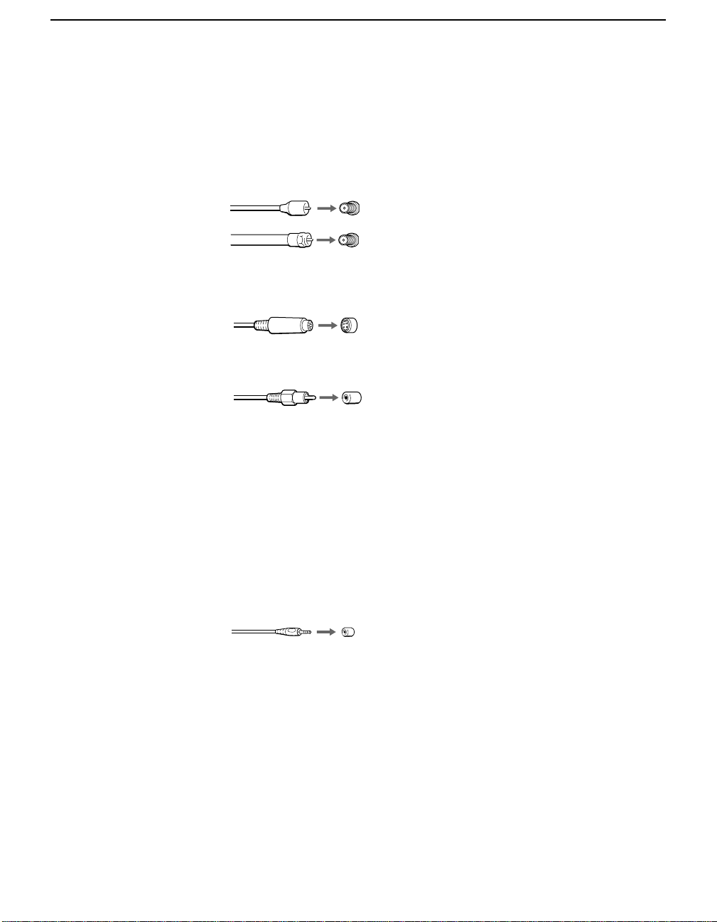
Connector Types
You may find it necessary to use some of the following connector types
during set up.
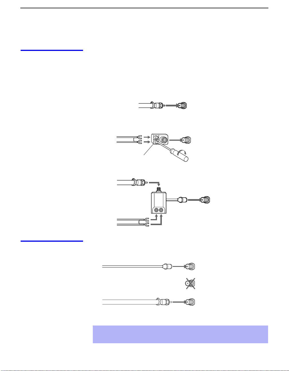
Coaxial cable
Standard TV cable and antenna cable
Plug Type
Screw-on Type
S Video cable
High quality video cable for enhanced picture quality
Audio/Video cabl e
Video - Yellow
Audio (Left) - White
Audio (Right) - Red
Push into connection.
Screw into connection.
Align guides and push
into connection.
Push into connection.
12
Some DVD Players are equipped with the following three video connectors:
Y - Green
P
(CB, Cb or B–Y) - Blue
B
P
(CR, Cr or R–Y) - Red
R
CONTROL S cable
CONTROL S connect ions are exclusive to Sony products and allow greater
control of all Sony equipment.
Push into connection.
Page 13
Installing and Connecting the Projection TV
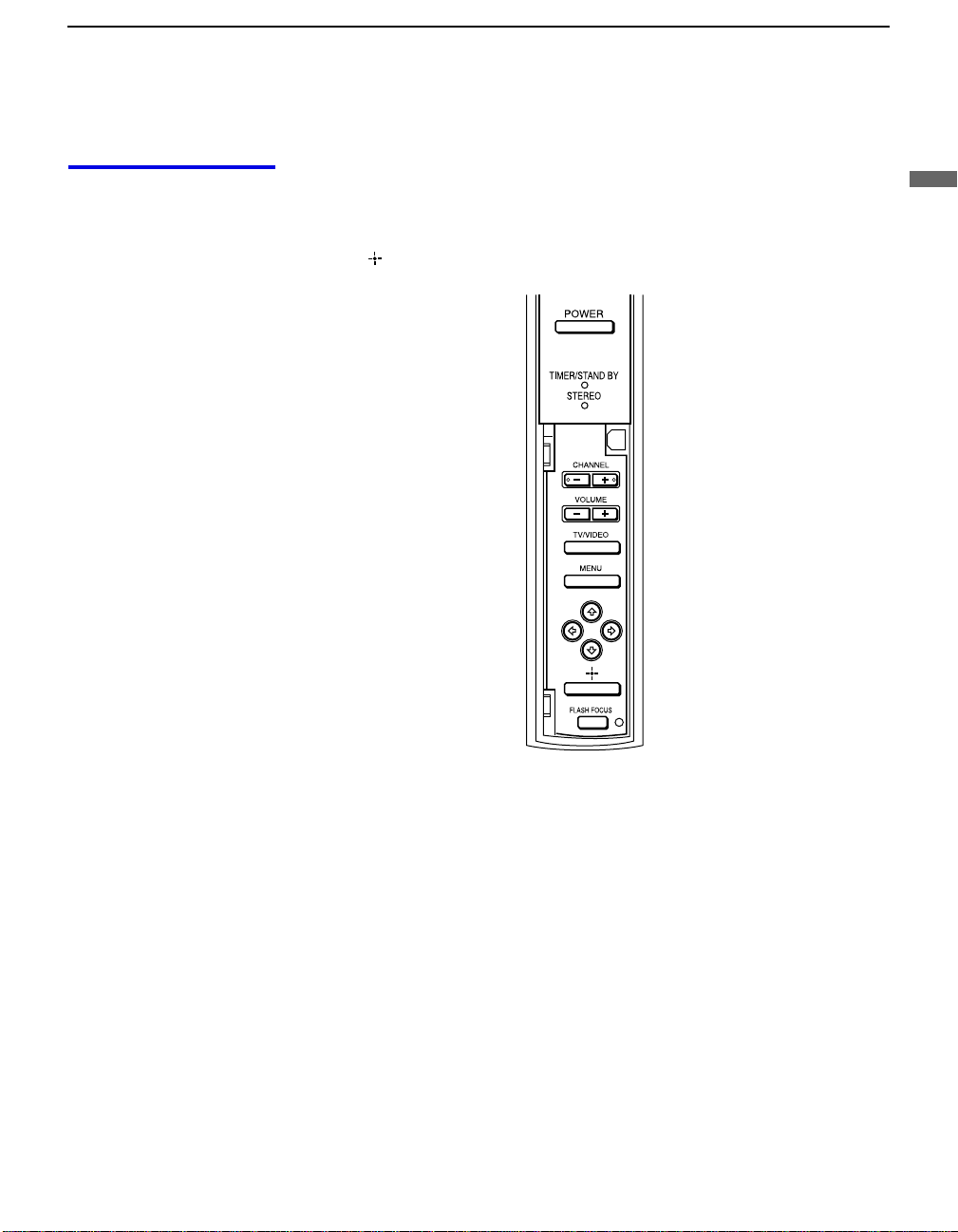
Projection TV Controls and Connectors
Front Panel Menu Controls
The front panel menu controls allow access to the on-screen menus without
the use of a remote control. Pressing MENU
The arrow buttons move the on-screen cursor in the menus and the Select
button ( ) selects the menu item.
brings up the on-screen menus.
Installing and Connecting the Projection TV
13
Page 14
Installing and Connecting the Projection TV
Projection TV Rear
and Front/Side
Rear of projection TV
Panel Connectors
Front or side of projection TV
14
KP-43HT20
KP-53HS20, KP-53HS30,
KP-61HS20 and KP-61HS30
Page 15

Installing and Connecting the Projection TV
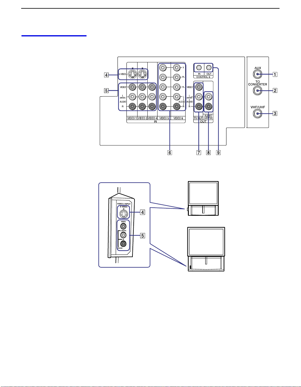
Connection Description
1 AUX Allows you to view local and cable channels if your cable
provider does not feature local channels. You can switch
between local and cable channels easily by pressing ANT
on the remote control. Devices connected to the AUX
input cannot be viewed in Twin View.
2 TO CONVERTER This is a VHF/UHF OUT jack that lets you set up your
projection TV to switch between scrambled channels
(through a cable box) and normal cable channels (CA TV).
Use this jack instead of a splitter to get better picture
quality when switching between scrambled and
unscrambled cable channels.
3 VHF/UHF Connects to your VHF/UHF antenna or cable.
4 S VIDEO
(Rear and front/
side)
5 VIDEO
(L/R)/AUDIO
(Rear and front/
side)
B/PR
6 Y/P
(L/R)/AUDIO
7 TV OUT Connects to an AV receiver for greater control of all audio
8 AU DI O OU T
(VAR/FIX)
L (MONO)/R
Connects to the S VIDEO OUT jack of your VCR or other
S VIDEO-equipped video component. Provides better
picture quality than the VHF/UHF jacks or the Video IN
jack.
Connects to the audio and video OUT jacks on your VCR
or other video component. A fourth vid e o input (VIDEO
2) is located on the side panel (for KP-43HT20) or the
front panel (for KP-53HS20, KP-53HS30, KP-61HS20
and KP-61HS30) of the projection TV.
Connects to your DVD player’s or Digital Set-top box’s
component video (Y, P
and video equipment (see page 30). For det a iled
information about connection, refer to the operating
manual supplied with the AV rece iver.
Connects to the left and right audio inputs of your audio or
video compone n t.
B, PR) and audio (L/R) jacks.
Installing and Connecting the Projection TV
9 CONTROL S
IN/OUT
To control other Sony equipment with the projection TV's
remote control, connect the CONTROL S IN jack of the
equipment to the CONTROL S OUT jack on the
projection TV with the CONTROL S cable.
To control the projection TV with a remote control for
another Sony product, connect the CONTROL S OUT
jack of the equipment to the CONTROL S IN jack on the
projection TV with the CONTROL S cable.
15
Page 16
Installing and Connecting the Projection TV
Basic Connections (Connecting Cable TV or Antenna)
Connecting Directly to Cable or an Antenna
The connection you choo se depends on t he cable foun d in your home. Ne wer
homes are equipped with standard coaxial cable (see A); older homes
probably have 300-ohm twin lead cable (see B); other homes may contain
both (see C).
A VHF Only or VHF/UHF or Cable
75-ohm coaxial
cable
B VHF Only or UHF Only or VHF/UHF
300-ohm twin lead cable
Antenna connector
C VHF and UHF
75-ohm coaxial cable
300-ohm twin lead cable
VHF/UHF
Rear of projection TV
VHF/UHF
U/V Splitter
(not supplied)
Rear of projection TV
VHF/UHF
Rear of projection TV
Cable and Antenna
16
If your cable provider does not feature local channels, you may find this set
up convenient.
CATV cable
(No connection to
TO CONVERTER)
Antenna cable
Select CABLE or antenna (ANT) mode by pressing
AUX
TO
CONVERTER
VHF/UHF
Rear of projection TV
ANT
on the remote
control.
To receive channels with an antenna, you need to turn your Cable to OFF
✍
(see page 52) and perform the Auto Program function (see page 53).
Page 17
Installing and Connecting the Projection TV
Cable Box Connections
Cable Box and Cable
This is the preferred basic cable TV hookup to use if:
❑
Your cable TV company scrambles some channels, but not all of them
(pay channels vs. regular cable channels) and you need to use a cable
box, and
❑
You want to enjoy the Twin View feature.
With this setup you can:
❑
Use the projection TV remote control to change channels using your
cable box when the signal is scrambled.
❑
Use the projection TV remote control to change channels using your
projection TV when the signal is not scrambled. (Your projection TV’s
tuner provides a better signal than the cable box.)
❑
Use the Twin View feature. (When all channels are routed through your
cable box, only one channel is sent to the proj ecti on TV, so yo u can no t
use the Twin View or Channel Index features for your cable box.)
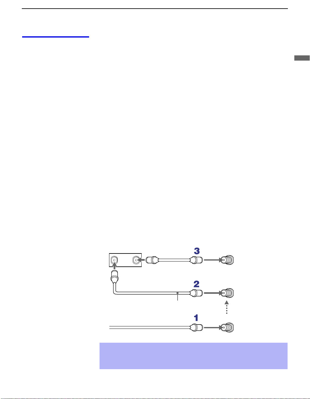
Connect the Cable TV cable to the projection TV’s VHF/UHF jack.
1
Using a coaxial cable, connect the projection TV’s TO CONVERTER
2
jack to the cable box’s IN jack. The projection TV’s internal converter
allows you to switch between unscrambled signals coming straight into
the projection TV and scrambled signals coming in through the cable
box, eliminating the need for an external splitter.
Installing and Connecting the Projection TV
Using a coaxial cable, connect the cable box’s OUT jack to the
3
projection TV’s AUX jack.
Cable box
IN
OUT
75-ohm coaxial cable (not supplied)
CATV cable (unscrambled channels)
✍
Pressing ANT on the remote control switches between the channels
AUX
Rear of
projection TV
TO
CONVERTER
Signal
VHF/UHF
coming in through the cable box (scrambled) and those coming directly
to the TV (unscrambled).
(Continued)
17
Page 18
Installing and Connecting the Projection TV
Cable Box Only
Use this hookup if:
❑
You subscribe to a cable TV system that uses scrambled or encoded
signals requiring a cable box to view all channels, and
❑
You do not intend to hook up any other audio or video equipment to
your projection TV.
When all channels are routed through your cable box, only one unscrambled
channel is sent to the projection TV, so you cannot use the Twin View
feature. If some channels are scrambled, but others are not, consider using
the hookup on page 17 instead.
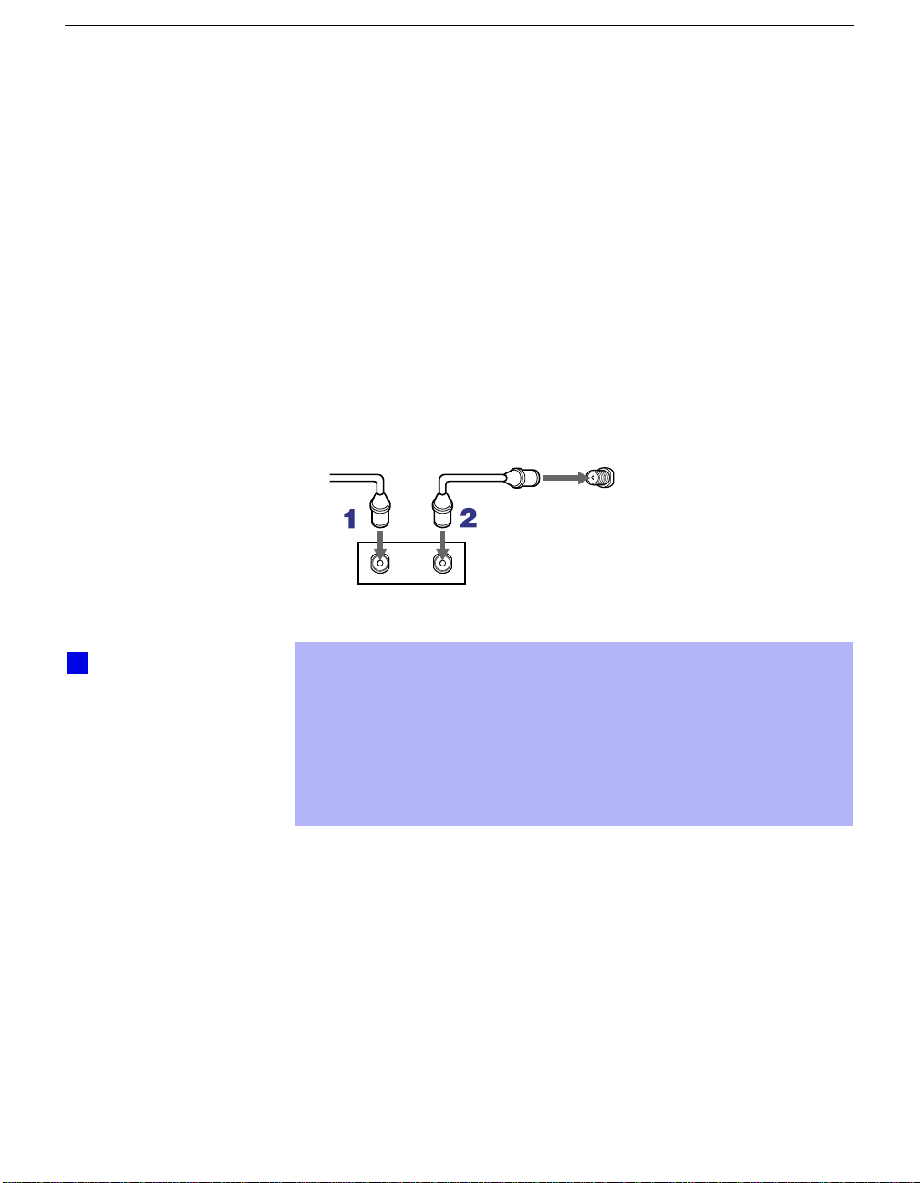
Connect the coaxial connector from your cable service to the cable
1
box’s IN jack.
Using a coaxial cable, connect the cable box’s OUT jack to the TV’s
2
VHF/UHF jack.
Cable
VHF/UHF
Rear of projection TV
z
Setting the Channel
Fix feature in the Channel
menu (see “Using the
Channel Menu” on page
52) ensures that you do
not accidentally switch
the channels using your
projection TV.
IN
Cable box
OUT
Also, set Cable to ON in the Channel menu. (see page 52)
✍
If you will be controlling all channel selection through your cable box,
consider using the Channel Fix feature to set your projection TV to
channel 3 or 4 (see page 53).
✍
Your So ny remote control can be progr ammed to operate your cable box
(see “Programmin g t he Remote Control” on page 65).
✍
To change channels using the cable box, set your projection TV to
channel 3 or 4 depending on the cable box channel output.
18
Page 19
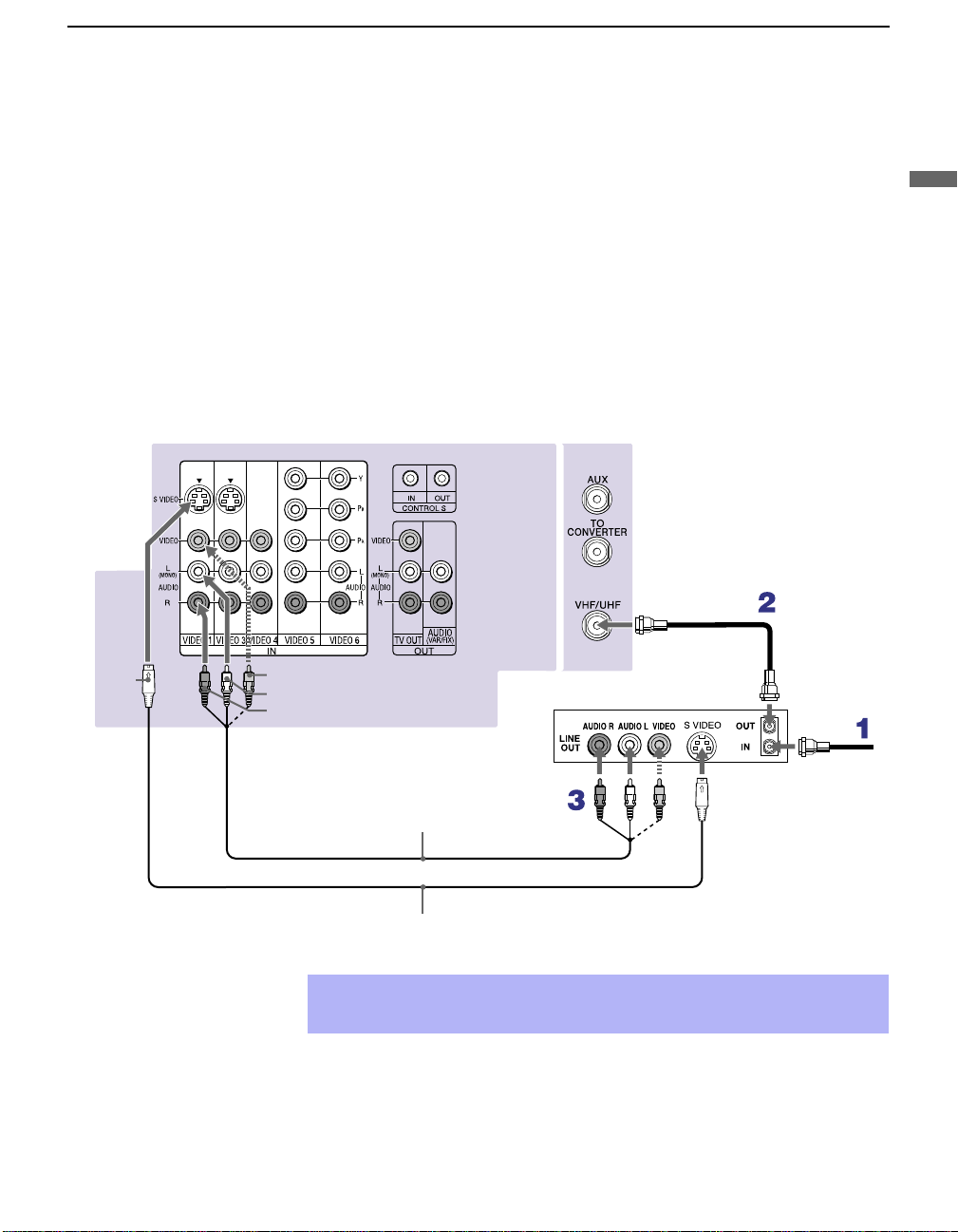
Connecting a VCR and Cable
Use this hookup if:
❑
You have cable TV that does not require a cable box.
Disconnect all power sources before making any connections.
Connect the cable TV cable to the VCR’s IN jack.
1
Using a coaxial cable, connect the VCR’s OUT jack to the projection
2
TV’s VHF/UHF jack.
Using AUDIO and S VIDEO cables, connect the VCR’s Audio and
3
S VIDEO OUT jacks to the projection TV’s AUDIO and S VIDEO IN
jacks.
Rear of Projection TV
Installing and Connecting the Projection TV
Installing and Connecting the Projection TV
Coaxial cable
S VIDEO
VIDEO (yellow)
AUDIO-L (white)
AUDIO-R (red)
YC-15V/30V (not supplied)
✍
If your VCR is not equipped with S VIDEO, use a VIDEO cable (yellow)
instead of the S VIDEO cable.
VMC-810S/820S
(not supplied)
VCR
Cable
19
Page 20

Installing and Connecting the Projection TV
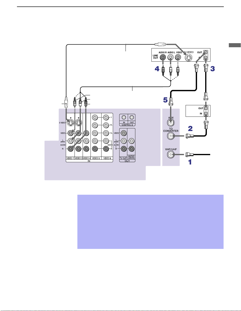
Connecting a VCR and Cable Box
Use this hookup if:
❑
Your cable TV company scrambles some channels, but not all of them
(pay channels vs. regular cable channels) and you need to use a cable
box, and
❑
You want to enjoy the Twin View feature.
With this setup you can:
❑
Use the projection TV remote control to change channels using your
cable box when the signal is scrambled.
❑
Use the projection TV remote control to change channels using your
projection TV when the signal is not scrambled. Your projection TV’s
tuner provides a better signal than the cable box.
❑
Use the Twin View feature. (When all channels are routed through your
cable box, only one signal is sent to the projection TV, so you cannot
use the Twin View feature.)
Disconnect all power sources before making any connections.
Connect the Cable TV cable to the projection TV’s VHF/UHF jack.
1
Using a coaxial cable, connect the TV’s TO CONVERTER jack to the
2
cable box’s IN jack. The projection TV’s internal converter allows you
to switch between unscrambled signals coming straight into the
projection TV and scrambled signals coming in through the cable box,
eliminating the need for an external splitter.
20
Using a coaxial cable, connect the cable box’s OUT jack to the VCR’s
3
IN jack.
Using AUDIO and S VIDEO cables, connect the VCR’s AUDIO and S
4
VIDEO OUT jacks to the projection TV’s AUDIO and S VIDEO IN
jacks.
Using a coaxial cable, connect the VCR’s OUT jack to the projection
5
TV’s AUX jack.
✍
To view scrambled channels, set your projection TV to AUX 3 or 4
(depending on your cable box output). Change channels using your
cable box.
Page 21
Installing and Connecting the Projection TV
S VIDEO
Rear of projection TV
VIDEO (yellow)
AUDIO-L (white)
AUDIO-R (red)
YC-15V/30V
(not supplied)
VMC-810S/820S
(not supplied)
Cable box
Coaxial cable
VCR
Coaxial
cable
Installing and Connecting the Projection TV
If your VCR is not equipped with S VIDEO, use a VIDEO cable (yellow)
✍
instead of the S VIDEO cable.
You will not be able to change channels on the VCR. Set your projection
✍
TV and VCR to channel 3 or 4, depending on your cable box channel
output.
Pressing ANT on the remote control switches between the channels
✍
coming in through the cable box (scrambled) and those coming directly
to the projection TV (unscrambled).
21
Page 22
Installing and Connecting the Projection TV
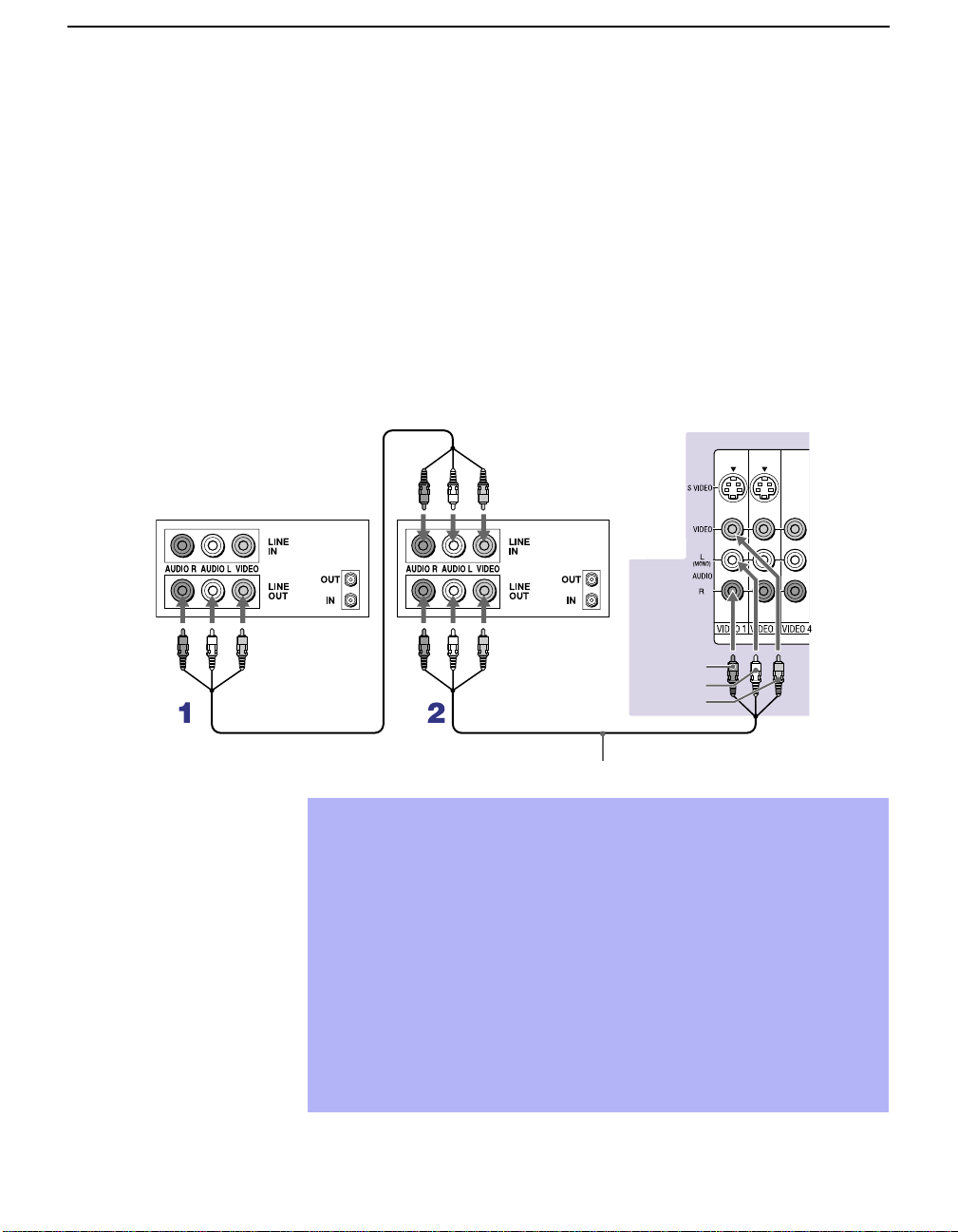
Connecting Two VCRs for Tape Editing
If you connect two VCRs, you can record from one VCR to the other while
using your TV to monitor what is be ing recor d ed.
Disconnect all power sources before making any connections.
Using AUDIO and VIDEO cables, connect the playback VCR’s Au di o
1
and Video OUT jacks to the recording VCR’s Audio an d Video IN
jacks.
Using AUDIO and VIDEO cables, connect the recording VCR’s
2
AUDIO and Video OUT jacks to the projection TV’s AUDIO and
VIDEO IN jacks.
Rear of projection TV
VCR (playback)
VCR (recording)
AUDIO-R (red)
AUDIO-L (white)
VIDEO (yellow)
VMC-810S/820S (no t su pp lie d)
T o p erform tape edit ing, set the p rojection TV to the video i nput i ntend ed
✍
for playback by pressing TV/VIDEO on the remote control.
You may need to change the video input on your VCR. Consult your
✍
VCR’s operating manual for instructions.
If your VCRs have an S VIDEO jack: For best picture quality, use an
✍
S VIDEO connection instead of the yellow video cable on your combined
A/V cable.
Using an S VIDEO cable, connect the playback VCR’s S VIDEO OUT jack
to the recording VCR’s S VIDEO IN jack. S VIDEO does not provide audio,
so audio cables must still be connected to provide sound.
You cannot record signals from equipment connected to the Y, PB, PR
✍
input.
22
Page 23
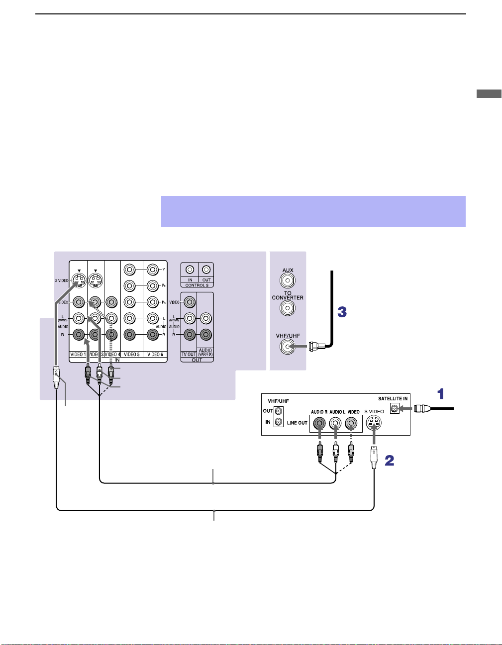
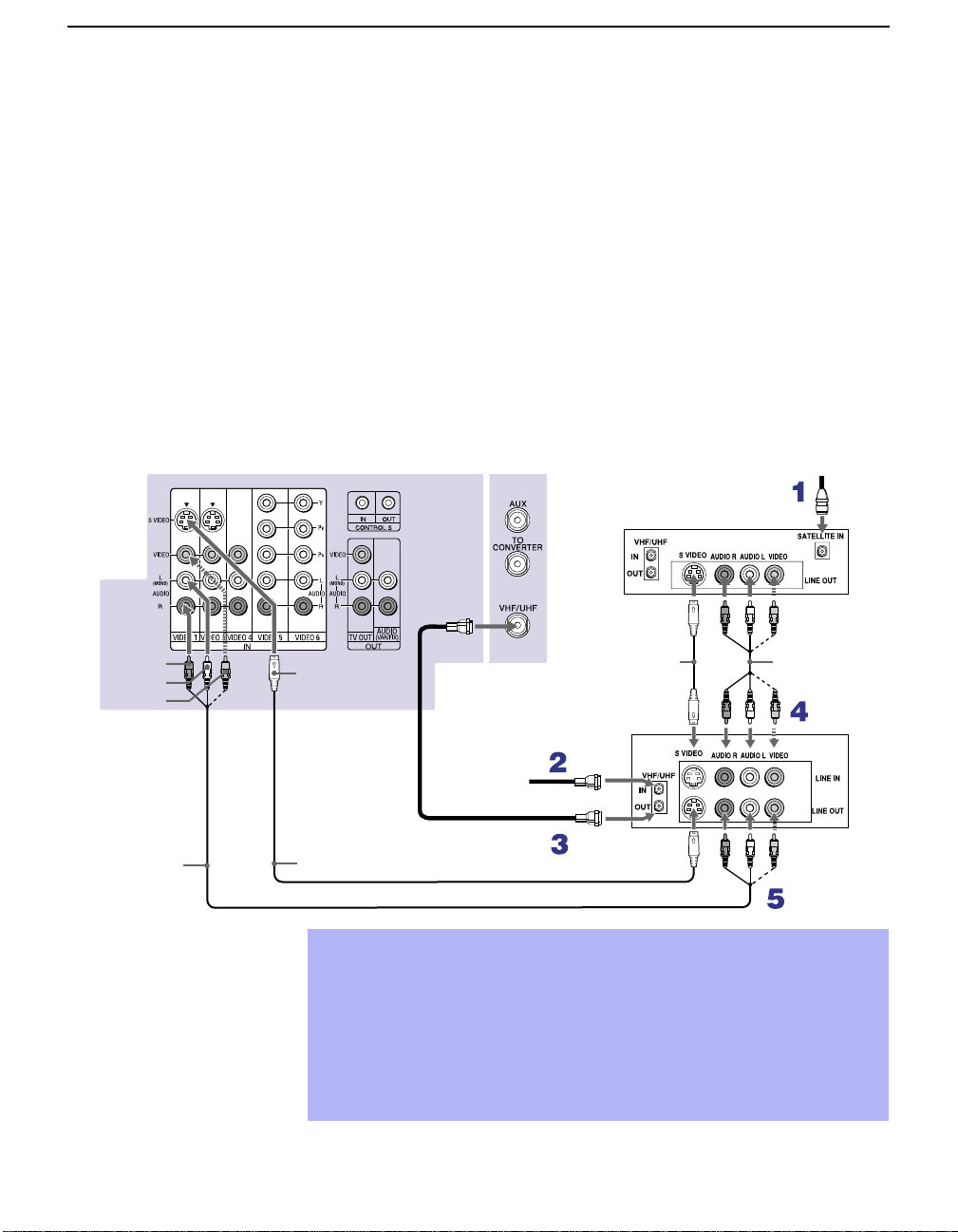
Connecting a Satellite Receiver
Disconnect all power sources before making any connections.
Installing and Connecting the Projection TV
ear of projection TV
1
2
3
✍
VIDEO (yellow)
AUDIO-L (white)
AUDIO-R (red)
Connect the satellite antenna cable to the satellite receiver’s
SATELLITE IN jack.
Using AUDIO and S VIDEO cables, connect the satellite receiver’s
A UD IO and S VIDEO OUT ja c ks to the projec t ion TV’s AUDIO and
S VIDEO IN jacks.
Connect a coaxial cable from your cable or antenna to the projection
TV’s VHF/UHF jack.
If your satellite receiver is not equipped with S VIDEO, use a VIDEO cable
(yellow) instead of the S VIDEO cable.
Coaxial
cable
Satellite receiver
Installing and Connecting the Projection TV
S
VIDEO
VMC-810S/820S (not supplied)
YC-15V/30V (not supplied)
Satellite
antenna
cable
23
Page 24
Installing and Connecting the Projection TV
Connecting a Satellite Receiver with a VCR
Disconnect all power sources before making any connections.
Connect the satellite antenna cable to the satellite receiver’s
1
SATELLITE IN jack.
Connect the CATV cable to the VCR’s VHF/UHF IN jack.
2
Using a coaxial cable, connect the VCR’s OUT jack to the projection
3
TV’s VHF/UHF jack.
Using AUDIO and S VIDEO cables, connect the satellite receiver’s
4
A UD IO and S VIDEO OUT ja c ks to the VCR’s AUDIO and S VIDEO
IN jacks.
Using AUDIO and S VIDEO cables, connect the VCR’s AUDIO and
5
S VIDEO OUT jacks to the TV’s AUDIO and S VIDEO IN jacks.
AUDIO-R (red)
AUDIO-L (white)
VIDEO (yellow)
VMC-810S/820S
(not supplied)
Rear of projection TV
Satellite receiver
Coaxial
cable
YC-15V/30V
S VIDEO
YC-15V/30V (not supplied)
Be sure your VCR’s video input is set correctly. Consult your VCR’s
✍
(not supplied)
VCR
Cable
operating manual for instructions.
Use TV/VIDEO to select
✍
- VIDEO 1 to watch satellite TV or the VCR (Your VCR must be turned on).
- VHF/UHF to watch cable TV.
If your VCR or satellite receiver is not equipped with S VIDEO, use a
✍
VIDEO cable (yellow) instead of the S VIDEO cable.
Satellite
antenna
cable
VMC-810S/
820S (not
supplied)
24
Page 25

Connecting an Audio Receiver
Disconnect all power sources before making any connections.
Using audio cables, connect the projection TV’s AUDIO OUT (VAR/FIX)
jacks to the audio receiver’s audio LINE IN jacks.
Rear of projection TV
Installing and Connecting the Projection TV
Installing and Connecting the Projection TV
AUDIO-R
(red)
Line
input
AUDIO-L
(white)
RK-74A
(not supplied)
25
Page 26

Installing and Connecting the Projection TV
Connecting a DVD Player with Component Video Connectors
This is the preferred hookup to use if:
❑
Your DVD player has component (Y, PB, PR) jacks.
Disconnect all power sources before making any connections.
Using three separate component vi deo cables, connect th e D VD player’s
1
Y, P
B and PR jacks to the Y, PB and PR jacks on the projection TV. Use
the VIDEO IN 5 or 6 connections.
✍
The Y, PB and PR jacks on your DVD player are sometimes label ed Y,
B
C
and CR, or Y, B-Y and R-Y. If so, connect the cables to like colors.
Using an audio cable, connect the DVD player’s Audio OUT jacks to
2
the projection TV’s AUDIO IN jacks. Be sure to use the same row of
inputs that you used for the video connection (VIDEO IN 5 or 6).
VMC-10HG (not supplied)
DVD player
R
P
P
B
Y
Rear of projection TV
26
AUDIO-R (red)
AUDIO-L (white)
RK-74A (not supplied)
Page 27

Installing and Connecting the Projection TV
Connecting a DVD Player with A/V Connectors
Use this hookup if:
❑
Your DVD player does not have component (Y, PB, PR) jacks.
✍
If your DVD player has video component output connectors: for best
picture quality use the connection described on page 26.
Disconnect all power sources before making any connections.
Using audio cables, connect the DVD player’s Audio OUT jacks to the
1
projection TV’s AUDIO IN jacks.
Using an S VIDEO cable, connect the DVD player’s S VIDEO jack to
2
the projection TV’s S VIDEO ja ck.
Rear or projection TV
S VIDEO
YC-15V/30V
(not supplied)
DVD player
Installing and Connecting the Projection TV
AUDIO-R (red)
AUDIO-L (white)
RK-74A (not supplied)
✍
Use TV/VIDEO on the remote control to switch between the VCR, DVD
player and cable TV inputs.
27
Page 28

Installing and Connecting the Projection TV
Connecting a Digital TV Receiver
Disconnect all power sources before making any connections.
z
Be sure to read the
Set-top box manual.
Using three separate component video cables, connect the Digital TV
1
Set-top box’s Y, PB
The Y, PB and PR jacks do not provide audio, so audio cables must
✍
be connected to provide sound.
Component video connection is necessary to view 480p, 720p and
1080i formats. You may also use the S VIDEO or Composite Video
connections, however, component video (Y, P
best picture quality for all format types.
Using an audio cable, connect the Digital TV Set-top box’s Audio OUT
2
jacks to the projection TV’s AUDIO IN jacks.
VMC-10HG (not supplied)
and PR jacks to the projection TV.
B
, PR) will provide the
R
P
P
B
Y
Rear of
projection TV
28
Digital TV Set-top box
AUDIO-R (red)
AUDIO-L (white)
RK-74A (not supplied)
You canno t record the signal from any equipment connected into the
✍
B
Y, P
and PR connectors.
This projection TV is not compatible with digital TV receivers
✍
configured with RGB or VGA output connectors.
Page 29

Connecting a Camcorder
For easy connection of the camcorder , the projection TV has front Aud io and
Video inputs (shown below). However, if you prefer, you can also connect
the camcorder to the projection TV’s rear Audio and Video IN jacks.
Using AUDIO and S VIDEO cables, connect the camcorder’s Audio and S
VIDEO OUT jacks to the projection TV’s AUDIO and S VIDEO IN ja c k s.
If you have a mono camcorder, connect its left audio output to the
✍
projectio n TV’s AUDIO L jack.
If your camcorder is not equipped with S VIDEO, use a VIDEO cable
✍
(yellow) instead of the S VIDEO cable.
S VIDEO
Installing and Connecting the Projection TV
Installing and Connecting the Projection TV
VIDEO (yellow)
AUDIO-L (white)
AUDIO-R (red)
KP-43HT20
YC-15V/30V (not supplied)
VMC-810S/820S
(not supplied)
KP-53HS20, KP-53HS30,
KP-61HS20, and KP-61HS30
A/V output
29
Page 30

Installing and Connecting the Projection TV
Connecting an AV Receiver
For greater control of all aud io and v ideo equipm ent, connect an AV receiv er.
Change “Video Label” for the VIDEO 1 input to “Receiver” (see page 64).
✍
Disconnect all power sources before making any connections.
Connect the coaxial cable from the incoming cable connection or
1
antenna to IN on the VCR.
Using a coaxial cable, connect OUT on the VCR to VHF/UHF on the
2
projection TV.
Using a VIDEO cable, connect VIDEO of VIDEO 1 IN on the
3
projection TV to MONITOR OUT on the AV receiver.
Using an A UDIO/VIDEO cable, connect TV OUT o n the pr ojection TV
4
to AUDIO/VIDEO 2 IN on the AV receiver.
Using an AUDIO/VIDEO cab le, connect the video equipment to the AV
5
receiver.
Select the Setup menu and set “Video Label” to “Receiver” to fix your
6
TV’s input to AV receiver (see “Video Label” on page 64).
VIDEO
Rear of projection TV
AUDIO-L
AUDIO-R
VMC-810S/820S (not supplied)
VMC-10HG (not supplied)
Coaxial cable (not supplied)
VIDEO
VMC-810S/820S
(not supplied)
AUDIO/
VIDEO 2 IN
MONITOR
OUT
VCR
AV receiver
VMC-810S/820S
(not supplied)
Cable/
Antenna
AUDIO/
VIDEO 1 IN
AUDIO/VIDEO 1 OUT
30
Page 31

Using the CONTROL S Feature
CONTROL S allows you to control your projection TV system and other
Sony equipment with one remote control. In addition to allowing you to
control multiple devices with one remote control, the CONTROL S feature
allows you to always point your remote control at your projection TV,
instead of having to point it at the other equipment, which might be hidden
or out of direct line of sight.
Rear of projection TV
Installing and Connecting the Projection TV
Installing and Connecting the Projection TV
31
Page 32

Installing and Connecting the Projection TV
Setting Up the Projection TV Au tomatically
After you finish connecting your projection TV, you can run Auto Setup to
set up your channels. The Auto Setup screen appears when you turn your
projection TV on for the first time after installing it. If you do not want to set
up the channels at this time, you can do it later by using the Auto Program
feature in the Channel menu (see page 53).
The Auto Setup feature does not apply for installations that use a cable
✍
box for all channel selection.
POWER on the front panel of your projection TV or on the remote
Press
Using Auto Setup
1
control
to turn on the projection TV.
Press the
2
briefly appear.
Press
3
exit. If you use the channel buttons on your remote control, be sure to
use the main set of buttons ( ).
TV (FUNCTION)
CH+
on your projection TV to run Auto Setup, or press
Projection TV front panel
button on your remote control. Red light will
CH–
to
32
You can run Auto Program by selecting it in the Channel menu, as
✍
described on page 53.
Page 33

Installing and Connecting the Projection TV
Adjusting the Convergence Automatically – FLASH FOCUS™ –
The projection tube image appears on the screen in three colors (red, green
and blue). If they do not converge, the color is poor and the picture blurs.
Before you use your projection TV, be sure to adjust the convergence.
The FLASH FOCUS feature allows you to adjust the convergence
automatically.
It is recommended to perform FLASH FOCUS about 30 min utes after the
✍
projection TV is first turned on.
Projection TV
front panel
Receive a TV or cable TV program.
1
FLASH FOCUS
2
Press
.
Installing and Connecting the Projection TV
The cross pattern shown below appears and FLASH FOCUS begins to
work. The adjustment is completed when the cross pattern becomes
white and you are returned to the program you were watching.
You cannot perform any other functions until FLASH FOCUS has
✍
completed its cycle.
If you perform any other operation while FLASH FOCUS is in progress,
✍
FLASH FOCUS operation is canceled.
Unshielded speakers or other metallic objects can cause picture
✍
distortion if placed close to the projection TV.
33
Page 34

Using the Features
Using the Remote Control
The following table describes the buttons on the remote control that are for
more advanced functions.
Button Descriptions
Outside Panel
Button Description
1 MUTING Press to mute the sound. Press again or press VOL + to
restore the sound.
2 SLEEP Press repeatedly until the projection TV displays the time
in minutes (15, 30, 45, 60, or 90) that you want the
projection TV to remain on before shutting off
automatically. Cancel by pressing until SLEEP OFF
appears or turning the power off. While the Sleep feature is
set, press once to view the remaining tim e.
3 ANT Changes between the VHF/UHF input and the AU X in put.
4 DISPLAY Press once to display the current time and channel label (if
set) and channel number. Press again to turn Display off.
See page 62 for details on setting the time.
5 JUMP Press to jump back and forth between two channe ls. The
projection TV alternates between the current channel and
the last channel that was selected.
6 FREEZE Freezes the window picture. Press again to resto re the
picture.
7 INDEX Press to enter the Channel Index mode. You can view and
select from twelve channels wit hout leaving the current
one.
8 The joystick allows for movement of the on-screen cursor.
Pressing down on the center of the joystick selects the item .
9 VOL +/– Adjusts the volume.
q; PIC MODE Press repeatedly to step through the available video picture
modes: Vivid, Standard, Movie and Pro. Also available in
the Video menu . For detail s, see “Selecting Video Options”
on page 48.
qa FAVORITES Displays the Favorite Channels list. For details, see “Using
Favorite Channels” on page 40.
qs RESET Press when in a menu to reset the settings to the factory
defaults.
34
Page 35

Using the Features
Button Description
qd POWER
buttons
(GREEN)
qf FUNCTION
buttons
qg TV/VIDEO
qh 0 – 9 and
ENTER
qj
GUIDE
qk MENU Press to display the pr ojection TV on-scr een menu. Press
ql CH +/– Scan through channels.
w; DRC/
CINEMOTION
Turn on and off the projection TV and other audio/video
equipment you h ave programmed into the remote control .
For instructions, see “Programming the Remote Control”
on page 65.
Select the equipment (TV, SAT/CABLE) t hat you want to
operate. The indicator lights up momentarily when pushed
to show which device the remote control is operating.
Cycles through the video equipment connected to your
projection
VIDEO 3, VIDEO 4, VIDEO 5
Press 0 - 9 to select a channel, the channel changes after 2
seconds. Press ENTER to select immediately.
Turns on/off Twin View. For details, see “Using Twin
View™” on page 41.
Displays the program guide of your satellite.
again to exit from the menu.
Press repeatedly to step throug h the available highresolution picture modes: Interlaced, Progressive and
CineMotion. For details, see “Usin g the Vid e o Me nu ” on
page 48.
TV’s video inputs: TV,
VIDEO 1, VIDEO 2
VIDEO 6
and
.
,
Using the Features
z
To scan rapidly through the
channels, press and hold do wn
CH+ or CH–.
35
Page 36

Using the Features
Inside Panel
Button Description
1 SYSTEM OFF Press to turn off the projection TV and all equipment
connected with S-Link.
2 N Play
3 m Rewind
4 REC Record
5 x Stop
6 DVD MENU Displays the DVD menu.
7 MTS/SAP Press to scroll through the Mu lti- channel TV So und (MT S)
options: Stereo, Auto SAP, and Mono.
8 CODE SET Used for programming the remote control to operate non-
Sony video equipment. For details, see “Programming t he
Remote Control” on page 65.
9 POWER Press to turn on the DVD/VCR player you have
programmed into the remote control. For instructions, see
“Programmin g the Rem ot e C on tr o l” on page 65.
q; M Fast-forward
qa Use to switch control for connect ed video equipment. You
can program one video source for each switch po sition. For
details, see “Programming the Remote Control” on page
65.
qs X Pause (Press again to resume normal pl ayback)
qd MENU Displays the video equipment menu.
qf M, m, <, ,,
and ENTER
Use to operate the DVD menu.
36
qg Press to select an audio opt ion: Steady Sound ON or
OFF.
Page 37

Watching the TV
Using the Features
Many TV features can be accessed directly through the remote control. The
following will explain the function of some of the buttons found on your
remote control.
Buttons for Projection TV Operations
1 TV (FUNCTION)
Activates the remote control for use with the projection TV.
2 ANT— (AUX input)
Press to change between the VHF/UHF input and the AUX input (for
detailed connection information, see “Cable and Antenna” on page 16 or
“Cable Box Connections” on page 17).
3 TV (POWER)
Turns the projection TV on and off. If a video input indication (e.g.,
VIDEO 1, VIDEO 2) appears on the screen, press
CH +/ –
4 0-9 and ENTER
Use for direct channel selection. Press
to select channel 10, press 1
or you can press ENTER
5 CH +/–
until a channel number appears.
and 0). The channel will change after 2 seconds,
for immediate selection.
0-9
to select a channel (for example,
TV/VIDEO
or
Press to scan through the channels (+ up or – down).
6 VOL +/–
Press to adjust the volume (+ up or – down).
7 JUMP
Press to alternate or jump back and forth between two channels. The
projection TV will jump between the current channel and the last channel
selected.
Using the Features
8 MUTING
Press to mute the sound. “MUTING” will appear on the screen and will dim
three seconds later. To restore the sound, press again or press VOL +
9 FREEZE — (yellow labeled button)
.
This is useful when you need to copy down information that appears on the
TV’s screen (see “Using the Freeze Function” on page 44).
37
Page 38

Using the Features
q; SLEEP
Press repeatedly until the projection TV displays the approximate time in
minutes (15, 30, 45, 6 0, o r 90 ) that yo u wa nt t he p roject i on TV to remain o n
before shutting off automatically.
Cancel by pressing SLEEP until “SLEEP OFF” appears or turning the
power off.
qa DISPLAY
Press to display the channel number, current time and channel label (if set).
To turn the display off, press
qs TV/VIDEO
DISPLAY
again.
Press repeatedly to scroll through available video inputs: TV, VIDEO 1,
VIDEO 2, VIDEO 3, VIDEO 4, VIDEO 5 and VIDEO 6.
If you select
Skip
as a
Video Label
in the Setup menu, your projection TV
will skip the video input you selected (see “Video Label” on page 64).
qd MTS/SAP
Press to scroll through the Multi-channel TV Sound (MTS) options (see
“MTS” on page 50).
qf PIC MODE
PIC MODE
Press
repeatedly to directly choose one of four different video
modes that best suits the program you are watching.
Vivid
: Select for enhanced picture contrast and sharpness.
Standard
: Select to display a standard picture for normal viewing
environments.
Movie
: Select to display a finely detailed picture for low light environments.
Pro (Professional)
: Select to display a picture with minimum enhancements.
When you select each mode, you can also adjust the picture quality (such as
Brightness, Color, etc.) to suit your taste. For details, see “Mode” on page
48.
38
Page 39

Watching the Digital TV
When you have connected the DTV receiver, you can enjoy digital TV
programs. This projection TV is capable of receiving the 1080i, 720p, 480p
and 480i digital TV formats.
This projection TV is not capable of displaying a native 720p format
✍
signal. When a 720p format signal is received, it is converted into a 480p
format signal.
To view a digital TV program
Connect the DTV receiver to VIDEO 5 or 6 IN on the projection TV.
1
(for details, see page 28)
Press
2
Select a digital channel on the DTV receiver. For details, see the
3
Operating Manual of the DTV receiver.
Adjust the volume of the projection TV as necessary.
4
TV/VIDEO
Using the Features
Using the Features
to select VIDEO 5 or 6.
39
Page 40

Using the Features
Using Favorite Channels
The Favorite Channel feature lets you select programs from a list of favorite
channels that you preset.
To display a list of your favorite channels:
Your Favorite Channel options can be set au tomaticall y or manu all y. Th e
✍
factory setting for Favorite Channel is Auto.
When Favorite Channel is set to Auto, the last eight channels selected
with 0-9 buttons will be set as Favorite Channel options. If you want to
input your own selections as Favorite Channel settings, see “Favorite
Channel” on page 52.
Press
1
The Favorite Channel options appear.
FAVORITES
.
Preview window
40
Move the joystick up or down to highlight the channel you want to
2
watch. The program on that channel appears in the preview window.
Press to select.
Page 41

Using Twin View™
Using the Features
Twin View enables you to watch two programs at the same time. You can
also change the size of both the left and right pictures.
Displaying T w in Pictures
Activating the Picture
To display twin pictures
Make sure your projection TV is
1
tuned to a working channel.
Press .
2
,
,
To cancel twin pictures
❑
Press again (or press ).
Although two pictures appear on the screen at the same time, only one
picture is active. Change the picture size by using the joystick. For an active
picture, you can:
❑
Change channels.
❑
Adjust the volume.
❑
Switch the input sources from VHF/UHF to cable by pressing ANT or
TV/VIDEO to switch the video input.
When the right picture is activated, the inpu t sources cannot be switched
to AUX by pressing ANT.
❑
Change the picture size by pressing the joystick up or down.
Using the Features
To activate the right picture
❑
Move the joystick to the right.
,
,
To activate the left picture
❑
Move the joystick to the left.
(Continued)
41
Page 42

Using the Features
When viewing an enhanced 16:9 picture, the aspect rati o changes to
✍
4:3 in Twin View. The picture will be reformatted to that aspect ratio.
If viewing a 720p or 1080i format input source, the aspect ratio will
✍
maintain the original 16:9 aspect ratio.
Hookups that affect your ability to use Twin View:
✍
- If you are viewing all channels through the cable box, the Twin
View feature will not work. The cable box only unscrambles one
signal at a time, so the right picture will be the same as the left
picture.
- You can watch a scrambled cable channel and another video
source. Be sure your DVD player, VCR or satellite receiver are
connected to one of the VIDEO IN 1-6 and AUX inputs on the rear
of the projection TV. Pictures from equipment connected to VIDEO
5, 6 and AUX will only appear in the left picture, not in the right.
The active picture is highlighted in cyan.
✍
42
Page 43

Using the Features
Changing the Picture Size
The zoom feature lets you change the size of the left and right pictures.
To enlarge the left
picture (reduce the
right)
Move the joystick
1
left to activate the
left picture (if not
already activated).
Move the joystick
2
up to enlarge the
picture and move
the joystick down
to reduce the
picture.
To enlarge the right
picture (reduce the
left)
Move the joystick
1
right to activate the
right picture (if not
already activated).
Move the joystick
2
up to enlarge the
picture and move
the joystick down to
reduce the picture.
Using the Features
When you adjust the twin screen sizes, the projection TV memorizes the
✍
change. The next time you use the Twin View function, the memorized
sizes appear.
43
Page 44

Using the Features
Using the Freeze Function
FREEZE
The
You can use this feature to write down information such as phone numbers,
recipes, etc.
To use the Freeze function
When the program information you want to capture is displayed, press
1
FREEZE
The projection TV switches to Twin View mode and displays the
2
“frozen” picture on the right, while the current program continues on th e
left.
button allows you to temporarily capture a program’s picture.
.
Current pr ogram
in progress
Call 555-1234
To cancel and return to normal viewing, press
3
Freeze feature is not available if you are alread y in Tw in View™ or INDEX
✍
mode.
FREEZE.
Frozen picture
44
Page 45

Using Channel Index
Channel Index allows you to display multiple channels and select one
directly.
The channels used for Channel Index will come directly from the projection
TV’s list of receivable channels (those set during “Auto Program” on page
53)
✍
To use the Channel Index function
1
Using the Features
Using the Features
Channel Index will not function when Parental Lock is activated. (See
“Using the Parent Menu” on page 54.)
Press .
The current channel will be reduced in size and displayed in the center
of the screen in normal motion picture format. The first twelve
receivable channels will appear one after another, clockwise, around the
center picture. These small pictures are updated in intervals of one
second. The channel number and channel caption (if set) on the second
and later appearances will dim.
A cyan-colored frame will appear to indicate current channel selection.
Move the joystick in any direction to move the cyan frame to the
2
channel that you wish to view, and press .
The selected channel will zoom in and move to the center, and the sound
of that channel will be heard.
(Continued)
45
Page 46

Using the Features
For the center picture you can:
❑
Change the channel by pressing
❑
Switch the input sources from VHF/UHF to cable by pressing
or to the video input by pressing TV/VIDEO
surrounding channels.
✍
Sound will only be heard from the center picture.
✍
If one of the pictures received through Channel Index is snowy, the
entire screen may become unstable. In this case, erase the snowy
channel. (see “Channel Skip/Add” on pa ge 53)
✍
If you leave the Channel Index screen displayed for an hour without
any additional operation, Channel Index is canceled and the normal
picture reappears.
If you wish to view another channel, repeat step 2.
3
To view another twelve channels, press
To view the previous twelve, press CH–
To view the normal picture of the selected channel, proceed to step 4.
Press .
4
The center picture will be enlarged for normal viewing.
0-9
and
CH+
.
ENTER
.
.
, without changing the
ANT
46
To cancel Channel Index
❑
Press again to resume normal viewing.
Page 47

Using the Menus
Overview
Opening and choosing a menu:
Press
1
Move the joystick to the desired menu icon and press to select it.
2
Use the joystick to scroll through the features.
3
See the specific menu page for instructions on moving through the
4
menu.
The menu gives you access to the following features:
Menu Icon Description Page
MENU
to display the menu screen.
Allows you to make adjustments to your picture settings.
It also allows you to customize the Picture Mode based on
the type of prog ram you are viewing.
48
To end a menu session:
Press MENU again.
To end one menu
session and move to
another:
Press the joystick B to
return to the menu icons.
Move the joystick to
choose the nex t menu icon
and press to select it.
Offers enhanced audio options such as listening to second
audio programming (SAP), or customizing the Effect of
the sound on your projection TV.
Allows you to set up a Favorite Channel list, run the Au to
Program function, and more.
Lets you control the viewing of programs based on their
ratings.
Lets you set the clock on your projection TV and allows
you to program your pro jecti on TV for sche dule d vie wing
using the Timers.
Provides several options for setting up your channels,
labeling your Video inputs, and selecting the language of
the on-screen menus.
50
52
54
62
63
47
Page 48

Using the Menus
Using the Video Menu
To select the Video Menu
MENU
Press
1
Move the joystick to the Video
2
icon and press .
Use the joystick to scroll
3
through the features.
Press to select a feature. That
4
feature’s adjustment appears .
Use the joystick to make the
5
desired adjustments.
Press to select/set.
6
Press
7
To restore the factory default settings for Picture, Brightness, Color,
Hue, Sharpness and Color Temp
❑
Press
.
MENU
to exit the menu screen.
RESET
on the remote control when in the Video menu.
Selecting Video Options
z
To quickly and easily
change from one Video
Mode to another, use the
PIC MODE on the remote
control.
The Video menu includes the following options.
Option Description
Mode
Customized
picture
viewing
Picture Adjust to increase picture contrast and deepen the color or decrease
Brightness Adjust to brighten or darken the pict ure.
Color Adjust to increase or decrease color intensity.
Hue Adjust to increase or decrease the green to nes.
Sharpness Adjust to sharpen or soften the picture.
Color Temp
White
intensity
adjustment
Vivid Select for enhanced picture contrast and
sharpness.
Standard Recom men de d for Norm al vie wing cond itio ns.
Movie Select for soft, film like, picture.
Pro Select for professional monitor like appearance.
✍
You can alter the Video menu settings (Pictu re, Brightness,
Color, etc.) for each Mode.
picture contrast and soften the col or.
Choose from three color temperatures:
Cool Sel ect to give the white colors a blue tint.
Neutral Select to give the white colors a neutral tint.
Warm Select to give the white colors a red tint (NTSC-
Standard).
48
Page 49

Option Description
DRC Mode
Digital
Reality
Creation
Creates a high-resolution picture with 4x density, for high quality
sources (i.e., DVD player, Satellite receiver).
Select from Interlaced, Progressive and CineMotion.
Interlaced Recommen de d f or moving pictures.
Progressive Recommended for still images and text.
CineMotion Recommended for 24 frame-per-second films.
Using the Menus
Using the Menus
49
Page 50

Using the Menus
Using the Audio Menu
To select the Audio Menu
MENU
Press
1
Move the joystick to the Audio
2
icon and press .
Use the joystick to scroll through
3
the options.
Press to select an option.
4
That option’s settings appear.
Use the joystick to scroll through
5
the settings.
Press to select the desired setting.
6
Press
7
To restore the factory default settings for Treble, Bass and Balance
❑
Press
.
MENU
to exit the menu screen.
RESET
on the remote control when in the Audio menu.
Selecting Audio Options
z
A virtual surround
system attempts to create
the same surround effect
produced by a
multichannel system using
only the left and right
speakers. Most effective
for program s enc od ed in
Dolby Surround.
The Audio menu includes the following options:
Option Description
Treble Adjust to increase or decrease higher-pitched sounds.
Bass Adjust to increase or decrease lower-pitched sounds.
Balance Adjust to emphasize left or right speak er balance.
Steady
Sound
Effect TruSurround Select for surround sound (for stereo programs
MTS
Enjoy stereo,
bilingual and
mono
programs
ON Select to stabilize the volume.
OFF Select to turn off Steady Sound.
only).
Simulated Adds a surround-like effect to mono programs.
OFF Normal stereo or mono reception.
Stereo Select for stereo reception when viewing a program
broadcast in stereo.
Auto-SAP Select to automatically switch the p ro jecti on TV to
second audio programs when a signal is received.
(If no SAP signal is present, the projection TV
remains in Stereo mode.)
Mono Select for mono reception. (Use to reduce noise
during weak stereo broadcasts.)
50
Page 51

Using the Menus
Option Description
Speaker ON Select to turn on the projection TV speakers.
OFF Select to turn off the projection TV speakers and
listen to the projection TV's sound only through
your external audio system speakers.
Audio Out
Easy control
of volume
adjustments
Variable The projection TV’s speakers are turned off, but
the volume outp ut from your aud io system can still
be controlled by the projection TV’s remote
control.
Fixed The projection TV’s speakers are turned off and the
volume, bass and treb le output of the pro jection TV
is fixed. Use your audio receiver’s volume control
to adjust the volume through your audio system.
Using the Menus
51
Page 52

Using the Menus
Using the Channel Menu
To select the Channel Menu
MENU
Press
1
Move the joystick to the Channel
2
.
icon and press .
Use the joystick to scroll
3
through the features.
Press to select a feature. That
4
feature’s options appear.
Use the joystick to scroll
5
through the options.
Press to select the desired option.
6
MENU
7
Press
to exit the menu screen.
Video Audio
Favorite Channel:Auto
Cable:ON
Channel fix:OFF
Auto Program
Channel Skip/Add
Channel Label
Move: Select: End:
Channel Setup
Parent
Timer
MENU
Selecting Channel Options
The Channel menu includes the following options:
Option Description
Favorite Channel Auto Select if you want Favorite Channel options to
be set automatically to the l ast eight channels
selected with the 0-9 buttons.
Manual Select if you want to input your own selections
as Favorite Channel options.
1
Press to select a favorite channel
number.
2
Use the joystick to scroll through the
channels until you find th e channel you
want to add to your f avorites.
3
Press to select it.
Cable ON Select if you are receiving cable channels with a
CATV cable.
OFF Select if you are using an antenna .
You should run Auto Program after changing the Cable
✍
setting.
52
Page 53

Using the Menus
Option Description
Channel Fix
Useful when you
have a cable box
or satellite
receiver connected
Auto Program Automatically programs the projection TV for all receivable
Channel
Skip/Add
Channel Label Label up to 20 channels with their station call letters.
2-6 “Fix” your projection TV’s cha nne l sett ing to 3
or 4 and use the cable box, VCR or satellite
receiver to change channels. Select one of these
settings if you have connected the devic e to th e
VHF/UHF jack.
AUX 2-6 Same as 2-6, except you select one of these
settings if you have connected the devic e to th e
AUX jack. (see page 15)
VIDEO 1 Use when connecting a cable box to co ntrol
external video sources. TV output should be
connected through the cable box.
channels.
Removes and adds viewable channels.
1
Use the joystick to scroll through the channels until you
find the channel you want to skip/add.
2
Press to select it.
3
Press the joystick up or down to toggle between “Add” and
“Skip.”
4
Press to select.
Using the Menus
53
Page 54

Using the Menus
Using the Parent Menu
The Parent menu allows you to set up the TV to block program s according to
their content and rating levels.
These ratings are assigned by a federal rating board. Not all programs are
rated. Using the Parental Lock blocks programs with a specific rating, but it
does not block an entire channel.
Channel Index will not fu nction when Parental Lock is activated.
✍
Using the Parent Menu
To select the rating
First, set a password, then select the country you reside in (U.S.A. or
Canada) an d your desired rating.
MENU
Press
1
Move the joystick to the Parent icon and press .
2
Use the
3
password.
Confirm your password by entering it again. Your password is stored
4
and the Parent menu options appear.
You need the password entered here for any future access into the Parent
✍
menu. If you lose your password, see “Lost password” on page 71.
If you want to change the password, see page 56.
✍
Make sure that “Country” is selected, and press .
5
.
0-9
buttons on the remote control to enter your four-digit
54
Page 55

Using the Menus
Move the joystick up or down to select U.S.A. or Canada according to
6
the country you reside in, and press .
Move the joystick down to select “Parental Lock”, and press .
7
Move the joystick up or down to select a desired rating, and press .
8
If you select Child, Youth, Young Adult or Custom, the P arental Contro l
is activated automatically.
If you want to select the ratings from Custom, see “Using Custom
Rating Options” on page 57.
Using the Menus
9
Press
MENU
to exit the menu screen.
(Continued)
55
Page 56

Using the Menus
z
If you are not familiar
with the Parental
Guideline rating system ,
you should select Child,
Youth, or Young Adult to
help simplify the rating
selection. To set more
restrictive ratings, select
Custom.
z
For descriptions of
Child, Youth, and Y oung
Adult ratings, see
pages 60 and 61.
The Parent menu includes the following options.
Option Description
Parental Lock
Turn ratings on/
off and select a
rating system
Change
Password
To deactivate the Parental Control feature
❑
Parental Lock
Set
OFF Parental lock is off. No programs are bloc ked
from viewing.
Child Maximum ratings permitted are:
❏ US: TV-Y, TV-G, G
❏ Canada: TV-Y, C, G
Youth Maximum ratings permitted are:
❏ US: TV-PG, PG
❏ Canada: TV-PG, PG, 8 ans+
Young Adult Maximum ratings permitted are:
❏ US: TV-1 4, PG-13
❏ Canada: TV-14, 14+, 13 ans+
Custom Select to set ratings manually.
❏ US: See page 60 for details.
❏ Canada: See page 61 for details.
For changing your password. (see below)
OFF
to
when in the Parent menu.
Viewing Blocked Programs
56
To change the password
Change Password
1
Select
option when in the Parent menu using the
joystick, and press .
Enter a new four-digit password using the
2
Confirm the new password by entering it again.
3
MENU
4
Press
to exit the menu screen.
0-9
buttons.
You can view a blocked program by entering the password.
ENTER
Press
1
Enter your password using the
2
when tuned to a blocked program.
0-9
buttons.
Parental Control will be canceled temporarily until you turn your
projection TV off.
Page 57

Using the Menus
Using Custom Rating Options
If you want to select the ratings to be blocked from Custom, follow the
procedure below.
Perform the steps 1 to 7 in “To select the rating” on page 54 to display
1
the Parental Lock options.
Move the joystick up or down to select “Custom,” and press .
2
Make sure that “Movie Ratings” is selected, and press .
3
Move the joystick up or down to select the rating to be blocked, and
4
press .
Using the Menus
The indicator automatically appears beside the selected rating and all
“higher” ratings, indicating that the programs that match the ratings will
be blocked.
To unbloc k a rating, s elect it by movin g t he joystick up or down, then
press . The indicator changes into “-” and all “lower” ratings are
unblocked.
(Continued)
57
Page 58

Using the Menus
Move the joystick left, then down, to select “TV Rating” or “Program,”
5
and press .
The “TV Rating” setting menu appears.
6
Move the joystick up or down to select the rating to be blocked, and
7
press .
The indicator automatically appears beside the selected rating and all
“higher” ratings, indicating that the programs that match the ratings will
be blocked.
To unbloc k a rating, s elect it by movin g t he joystick up or down, then
press . The indicator changes into “-” and all “lower” ratings are
unblocked.
Some TV ratings have additional content ratings called “extenders.” The
extenders are defined as follows: D (sexually suggestive Dialog), FV
(Fantasy Violence), L (coarse Language), S (Sexual situations) and V
(Violence). By setting the extenders, you can define additional viewing
limits. All of the extenders included in the selected ratings will be
blocked. If you wish to allow any of them to be viewed, go to step 8.
58
Page 59

Using the Menus
Move the joystick left or right to select the extender to be viewed, and
8
press .
“–” appears beside the selected extender, indicating that the programs
that match the extender can be viewed.
If you press again, is displayed to show that the programs that
match the extender will be blocked again.
Repeat step 8 for other extenders.
9
All programs that match the ratings you select and higher, except for the
extenders that were canceled, will be blocked.
MENU
10
Press
to exit the menu screen.
Using the Menus
59
Page 60

Using the Menus
US custom rating options
If you selected U.S.A. as the country of residence on page 54, the Custom
Rating Menu includes the following options. (If you selected Canada, see
page 61.)
z
To ensure maximum
blocking capability, the
age-based ratings shoul d
be blocked.
z
If you choose to block
unrated TV programs,
please be aware that the
following programs may
be blocked: emergency
broadcasts, political
programs, sports, news,
public ser v ice
announcements, religious
programs and weath er.
Option Description
Movie Rating G All children and General Audience.
PG Parental Guidance suggested.
PG-13 Parental Guidance for children under 13.
R Restricted viewing, parental guidance is suggested
for children under 17.
TV Rating
Block programs
by their rating,
content or both
Unrated
Block programs
or movies that
are broadcast
NC-17
and X
Age-Based Options
TV-Y All children.
TV-Y7 Directed to older children.
TV-G General Audience.
TV-PG Parental Guidance suggested.
TV-14 Parents Strongly cautioned.
TV-MA Mature Audience only.
Content-Based Options
FV Fantasy Violence.
D Suggestive Dialogue.
L Strong Language.
S Sexual situations.
V Violence.
Block Blocks all programs and movies that are broadcast
Allow Allows programs and movies that are broadcast
No one 17 and under allowed.
without a rating.
without a rating.
without a r ating
60
The content ratings will increase depending on the level of the age-based rating.
✍
For example, a program with a TV-PG V (Viole nce) rating may contain mode rate
violence, while a TV-14 V (Violence) rating may contain more intense violence.
Page 61

Using the Menus
Canadian custom rating options
If you selected Canada as the country of residence on page 54, the Custom
Rating Menu includes the following options. (If you selected U.S.A., see
page 60.)
Option Description
English Rating C All children.
C8+ Childre n 8 ye ars and older.
G General programming.
PG Parental Guidance.
14+ Vi ew ers 14 and older.
18+ Adult programming.
French Rating G General programming.
8 ans+ Not recommended for young childre n.
13 ans+ Not recommended for ages und er 13.
16 ans+ Not recommended for ages und er 16.
18 ans+ Programming restricted to adults.
USA Rating See “TV Rating” on page 60 for details.
Using the Menus
61
Page 62

Using the Menus
Using the Timer Menu
To select the Timer menu
MENU
Press
1
Move the joystick to the Timer
2
icon and press .
To set the Current Time
Use the joystick to select
1
“Current Time”, then press .
If it is currently Daylight Saving
2
Time, be sure to set the mode to
“ON” first.
Use the joystick to enter the correct time, then press .
3
Press
4
To set the Timer
Before setting the timer, be sure to set your projection TV’s clock to the
current time and Daylight Saving Mode.
Move the joystick to “Timer 1” or “Timer 2”, then press .
1
.
MENU
to exit the menu screen.
Selecting Timer Options
62
Use the joystick to enter your day, time and channel preferences, then
2
press to select each one.
MENU
Press
3
To reset the Clock or Timers
❑
Press
Timer menu.
The Timer menu includes the following options:
Option Description
Timer 1
Timer 2
Current Time Set the current time.
Daylight Saving ON Select in the Spring to adjust the time during
to exit the menu screen.
RESET
on the remote control after selecting that option in the
Program Select to set the Timer by day, time, duration,
OFF Select to turn off the Timer. (Your previous
OFF Select in the Fall to adjust the time at the end
and channel.
settings will be saved.)
Daylight Saving Time.
of Daylight Saving Time.
Page 63

Using the Setup Menu
To select the Setup Menu
MENU
Press
1
Move the joystick to the Setup
2
icon and press .
Use the joystick to scroll through
3
the features.
Press to select a feature. That
4
feature’s options appear.
Use the joystick to scroll through
5
the options.
Press to select the desired option.
6
MENU
Press
7
Using the Menus
.
Using the Menus
to exit the menu screen.
Selecting Setup Options
The Setup menu includes the following options:
Option Description
Caption Vision Allows you to select from three closed caption modes (for
programs that are broadcast with close d captioning).
OFF Turns off Caption Vision.
CC1, CC2,
CC3, CC4
TEXT1, TEXT2,
TEXT3, TEXT4
XDS
(Extended Data
Service)
Displays a printed version of the
dialog or sound effects of a program.
(Should be set to CC1 for most
programs.)
Displays network/station informatio n
presented using either half or the
whole screen (if available). For closed
captioning , set to CC1.
Displays a netwo r k na m e, pro g r am
name, program length, and time of the
show if the broadcaster offers this
service.
(Continued)
63
Page 64

Using the Menus
z
To use this feature
with widescreen DVDs,
set your DVD player to
16:9 aspect ratio.
Option Description
Video Label Allows you to label the audio/video components you connected
to the projection TV so you can identify them when using TV/
VIDEO. When in the Setup menu’s Video Label featu re, use
the joystick to highlight an input to label, then press to
select it. Use the joystick to scroll through the labels. Press
to select the component y ou connected to each of the input
jacks on the back of your projection TV. Select “Skip” if you do
not have a component connected to a particular set of inpu t
jacks.
VIDEO 1 VHS, 8mm, Beta, LD, Game, SAT,
DVD, Web, Receiver, DTV, Skip
VIDEO 2/3/4 VHS, 8mm, Beta, LD, Game, SAT,
DVD, Web, DTV, Skip
VIDEO 5/6 DVD, DTV, HD, Skip
If you select “Skip”, your projection TV skips this conne c tio n
when you press TV/VIDEO.
When you select “Receiver” on Video Label, your projection
✍
TV’s input is fixed.
Language Select to display all on-screen menus in your language of
choice: English, Español, Français.
16:9 Enhanced Provides enhanced picture resolution for widescreen sources,
such as selected DVD titles (only available when the projection
TV is in VIDEO mode). Press TV/VIDEO and select from one
of the following options:
AUTO To activate automatically wh en a 16:9
signal is received.
ON To activate manually.
OFF To deactivate manually.
64
AUTO/ON will appear when the projection TV is in VIDEO mode 1-6.
✍
ON/OFF will appear when the p rojection TV is in VIDEO mode 5-6 and the
480p signal occurs.
Page 65

Other Information
Programming the Remote Control
The remote control is preset to operate Sony brand video equipment.
Sony
Equipment
Beta, ED Beta VCRs AV1 303
8 mm VCR AV2 302
VHS VCR AV3 301
DVD Player DVD 751
If you have video equipment other than Sony brand that you want to control
with the projection TV’s remote control, use the following procedures to
program the remote control.
The equipment must have infrared (IR) remote capability in order to be
✍
used with the remote control.
From the “Manufacturer’s Codes” listed on page 67, select the three-digit
code number for the manufacturer’s code for your component. If more than
one code number is listed, start with the number listed first. Use the code
number to complete the following procedure.
To program a cable box or a satellite receiver
Open the panel of the remote control.
1
CODE SET
Press
2
Close the panel and press
3
Switch Position
on Remote Control
inside the panel.
SAT/CABLE (FUNCTON)
Programmable
Code Number
.
Enter the three-digit manufacturer’s code number using the
4
ENTER
Press
5
To check if the code number works, aim the projection TV’s remote
6
control at the component and press the green POWER
corresponds with that component. If it responds, the programming is
completed. If not, try using the other codes listed for that manufacturer.
.
0-9
button that
(Continued)
buttons.
65
Page 66

Other Information
To program video equipment
Open the panel of the remote control.
1
Move the slide switch to the desired component type.
2
CODE SET
Press
3
✍
You must perform step 4 within 10 seconds of step 3, or you must
start again from step 3.
Close the panel and enter the three-digit manufacturer’s code number
4
using the
Press
5
To check if the code number works, aim the projection TV’s remote
6
control at the component, open the panel, and press the green
button. If it responds, the programming is completed. If not, try using
the other codes listed for that manufacturer.
0-9
ENTER
inside the panel.
buttons.
.
POWER
66
Tips
❑
If more than one code number is listed, try entering them one by one
until you come to the correct code for your component.
❑
If you enter a new code number, the code number you previously
entered at that setting is erased.
❑
In some rare cases, you may not be able to operate your component with
the Sony rem ote control. In this case, use the compone nt’s own remote
control unit.
Page 67

Other Information
Manufacturer’s Codes
VCRs
Manufacturer Code
Sony 301
Admiral
(M. Ward)
Aiwa 338, 344
Audio Dynamic 314, 337
Broksonic 319, 317
Canon 309, 308
Citizen 332
Craig 302, 332
Criterion 315
Curtis Mathes 304, 338, 309
Daewoo 341, 312, 309
DBX 314, 336, 337
Dimensia 304
Emerson 319, 320, 316,
Fisher 330, 335
Funai 338
General Electric 329, 304, 309
Go Video 322, 339, 340
Goldstar 332
Hitachi 306, 304,
Instant Replay 309, 308
JC Penney 309, 305, 304,
JVC 314, 336, 337,
Kenwood 314, 336, 332,
LXI (Sears) 332, 305, 330,
Magnavox 308, 309, 310
Marantz 314, 336, 337
Marta 332
Memorex 309, 335
327
317, 318, 341
305, 338
330, 314, 336,
337
345, 346, 347
337
335, 338
Manufacturer Code
Minolta 305, 304
Mitsubishi/
MGA
Multitech 325, 338, 321
NEC 314, 336, 337
Olympic 309, 308
Optimus 327
Panasonic 308, 309, 306,
Pentax 305, 304
Philco 308, 309
Philips 308, 309, 310
Pioneer 308
Quasar 308, 309, 306
RCA/
PROSCAN
Realistic 309, 330, 328,
Sansui 314
Samsung 322, 313, 321
Sanyo 330, 335
Scott 3 12, 313, 321,
Sharp 327, 328
Shintom 315
Signature 2000
(M. Ward)
SV2000 338
Sylvania 308, 309, 338,
Symphonic 338
Tashiro 332
Tatung 314, 33 6, 337
Teac 314, 336, 338,
Technics 309, 308
Toshiba 312 , 311
323, 324, 325,
326
307
304, 305, 308,
309, 311, 312,
313, 310, 329
335, 324, 338
335, 323, 324,
325, 326
338, 327
310
337
Manufacturer Code
Wards 327, 328, 335,
331, 332
Yamaha 314, 33 0, 336,
337
Zenith 331
DVD Players
Manufacturer Code
Sony 751
Panasonic 753
Pioneer 752
RCA 755
Toshiba 754
Cable Boxes
Manufacturer Code
Hamlin/Regal 222, 223, 224,
225, 226
Jerrold/G. I. 2 01, 202, 203,
204, 205, 206,
207, 208, 218
Oak 227, 228, 229
Panasonic 219, 220, 221
Pioneer 214, 215
Scientific
Atlanta
Tocom 216, 217
Zenith 212, 213
Satellite Receivers
Manufacturer Code
Sony 801
General
Electric
Hitachi 805
Hughes 804
Panasonic 803
RCA/
PROSCAN
Toshiba 806, 807
209, 210, 211
802
802, 808
Othe r Informa t ion
67
Page 68

Other Information
Operating Other Components with Your Projection TV Remote Control
Operating a VCR
Operating a DVD Player
Open the panel and move the slide switch to the AV input you coded for this
device.
To Do This ... Press
Turn on/off green POWER button (inside the panel)
Change channels CH +/–
Record N and REC simultaneously
Play N
Stop x
Fast forward M
Rewind the tape m
Pause X (press again to resume normal playback)
Search the picture
forward or backward
Change input mode Slide switch
M or m during playback
(release to resume normal playback)
Open the panel and move the slide switch to the DVD input you coded for
this device.
To Do This ... Press
Turn on/off green POWER button (inside the panel)
Play N
Stop x
Pause X (press again to resume normal playback)
Step through different tracks of
an audio disc
Step through different chapters
of a video disc
Display the DVD menu DVD MENU
Display the menu (Setup) MENU
Operate the DVD menu M, m, <, ,, ENTER
M to step forward or m to step backward
CH+ to step forward or CH– to step backward
68
Page 69

Operating a Cable Box
Operating a Satellite Receiver
To Do This ... Press
Turn on/off SAT/CABLE (POWER)
Select Cable Box SAT/CABLE (FUNCTION)
Select a channel 0-9 buttons, ENTER
Change channels CH +/–
Back to previous channel JUMP
To Do This ... Press
Turn on/off SAT/CABLE (POWER)
Select Satellite Receiver SAT/CABLE (FUNCTION)
Select a channel 0-9 buttons, ENTER
Change channels CH +/–
Back to previous channel JUMP
Display channel number DISPLAY
Display DBS guide GUIDE
Display DBS menu MENU
Move highlig ht ( c urs o r) Joystick or arrows
Select item
Other Information
Othe r Informa t ion
69
Page 70

Other Information
Troubleshooting
If, after reading these operating instructions, you hav e ad d itiona l qu esti ons re late d to the use of your
Sony television, plea se call our Cust omer Infor mation Services Cen ter at 1-800-222-SO NY (7669) (U .S.
residents only) or (416) 499-SONY (7669) (Canadian residents only).
Problem Possible Remedies
No picture
(screen not lit),
no sound
Remote control
does not operate
Dark, poor or no
picture (screen lit),
good sound
Good picture,
no sound
Cannot receive digital channels
(when a DTV receiver is
connected)
Cannot receive upper channels
(UHF) when using an antenna
No color ❏ Adjust the Color settings in the Video menu (see page 48).
Only snow and noise
appear on the screen
Dotted lines
or stripes
❏ Make sure the projection TV’s power cord is connected securely to the wall outlet.
❏ Push the power button on the front of the projection TV.
❏ Check to see if the TV/VIDEO setting is correct: when watching TV, set to TV,
and when watching connect ed equipment, set to VIDEO 1, 2, 3, 4, 5 or 6.
❏ Try another channel. It could be station trouble.
❏ The Parental Control feature is activated (see “Using the Parent Menu” on pag e
54).
❏ If your projecti on TV does no t tur n on , an d a red ligh t kee p s flas hin g, your
projection TV may need service. Call your local Sony Service Center.
❏ Batteries could be weak. Replace the b atteries.
❏ Press TV (FUNCTION) when operating yo ur pro j e ct ion TV.
❏ Make sure the projection TV’s power cord is connected securely to the wall outlet.
❏ Locate the projection TV at least 3-4 feet away from fluorescent lights.
❏ Check the orientation of the bat teries.
❏ Adjust the Picture setting in the Video menu (see page 48).
❏ Adjust the Brightness setting in the Video menu (see page 48).
❏ Check antenna/cable connections.
❏ Adjust the convergence aga in using FLASH FOCUS (see “Adjusting the
Convergence Automatically – FLASH FOCUS™ –” on page 33).
❏ Press MUTING so that “MUTING” disappears from the screen (see page 34).
❏ Make sure Speaker is set to ON in the Audio menu (see page 51).
❏ Check the MTS setting in the Audio menu (see “MTS” on page 50).
❏ Check the connections between the DTV receiver and the projection TV (see page
28).
❏ Check your local listings to find out if you can receive digital broadcasts in yo ur
area.
❏ Change Cable to OFF (se e pa ge 52).
❏ Use Auto Program in the Channel menu to ad d receivable channels that are not
presently in TV memory (see page 53).
❏ Check the Cable setting in the Channel menu (see “Cable” on page 52).
❏ Check the antenna/cable connections.
❏ Make sure the channel is broad casting programs.
❏ Press ANT to change the input mode (see page 37).
❏ Adjust the antenna.
❏ Move the projection TV away from noise sources such as cars, neon signs, or hair-
dryers.
70
Page 71

Other Information
Problem Possible Remedies
Projection TV is fixed to one
channel
Double images or ghosts ❏ Use a highly directional ou tdoor antenna or a ca ble ( when th e proble m is ca used by
Cannot operate menu ❏ If the item you want to choose appears in gray, you canno t select it.
Cannot receive any channels
when using cable TV
Cannot gain enough volume
when using a cable box
Channel Index does not display
all available channels
Cannot receive channels
Unable to select a channel
Lost password ❏ In the password screen (see page 54), enter the following master password: 4357.
Cannot change channel s w ith
the remote control
Cannot cycle through the other
video equipment connected to
the projection TV
There is a black box on th e
screen
There is no twin picture or it is
just static
❏ Use Auto Program in the Channel menu to ad d receivable channels that are not
presently in TV memory (see page 53).
❏ Check your Channel Fix settings (see page 53).
reflections from nearby mountains or tall buildings).
❏ Turn the projection TV’s power off and on aga i n .
❏ Use Auto Program in the Channel menu to ad d receivable channels that are not
presently in TV memory (see page 53).
❏ Check your cable settings.
❏ Make sure Cable is set to ON in the Channel menu (see page 52).
❏ Increase the volume of the cable box using the cabl e box’s remote control. Then
press TV (FUNCTION) and adjust the projection TV’s volume.
❏ Make sure Cable is set to ON in the Channel menu (see “Cable” on page 52).
❏ Use Auto Program in the Channel menu to add receivable TV channels that are
not presently in TV memory (see page 53 ).
❏ Use Auto Program in the Channel menu to add receivable TV channels that are
not presently in TV memory (see page 53 ).
The master password clears your previous password; it cannot be used to
temporarily unblock channels.
❏ Be sure you have not inadvertently switched your projection TV from channel 3 or
4 setting if you are using another device to change channels.
❏ If you are using another device to control channels, be sure the “function” button
for that device has been pressed, or the slide switch is set correctly. For example, if
you are using your cable to control channels, be sure to press SAT/CABLE.
❏ Be sure the Video Label feature has not been set to Skip (see page 64).
❏ You have selected a text option in the Setup menu and no text is available (see
page 63 to reset Setup selections). To turn this feature off, select OFF in the
Caption Vision option. If you were trying to get closed captioning, sel e ct CC1
instead of Text 1-4.
❏ Be sure your twin picture is set to a vid eo so urce/chann el that ha s a program airing.
❏ You may be tuned to a video input with nothing connected to it. Try cycling
through your video inputs using TV/VIDEO.
❏ Twin View is not set to receive a signal from the AUX input. If you have
connected a VCR, DVD player or satellite receiver to the AUX input on the
projection TV, it will not show in the second picture.
Othe r Informa t ion
(Continued)
71
Page 72

Other Information
Problem Possible Remedies
Y ou get the same program in the
window picture as in the main
picture
You cannot get anything but TV
channels in your second picture
Favo rite Channe l do es no t
display your choi ces
Some video sources do not
appear when you press TV/
VIDEO
❏ Both may be set to the same channel. Try changing channels in either the main
picture or the window pi cture.
❏ You may be running all your channels through a cable box. The cable box will
only unscramble one signa l at a time, so you cannot use the Twin View feature. If
possible, run a direct cable to your projection TV’s VHF/UHF input (this will only
work if your cable system pr ovides an unscrambled signal).
❏ Be sure the video label has not been set to skip your video inputs. See the Setup
menu on page 63.
❏ Verify that F avorite Channel is set to Manual in the Channel menu (see
“Favorite Channel” on page 52).
❏ Ensure that Video Label is not set to SKIP (see “Video Label” on page 64).
72
Page 73

Other Information
Specifications
Projection System 3 picture tubes, 3 lenses, horizontal in-line system
Picture Tube 7-inch high-brightness monochrome tubes (6.3 raster size), with optical
coupling and liquid cooling system
Projection Lense s High performance, larg e
diameter hybrid lens F1.1
Antenna 75 ohm external terminal for VHF/UHF
Television System NTSC, American TV Standard
Screen Size (measured diagonally) 43 in ches (KP-43HT20)
53 inches (KP-53HS20, KP-53HS30)
61 inches (KP-61HS20, KP-61HS30)
Channel Coverage
VHF 2-13
UHF 14-69
CATV 1-125
Power Requirements 120V, 60 Hz
Number of Inputs/Outputs
Video (IN) 4 1 Vp-p, 75 ohms unbalanced, sync negative
S Video (IN) 3 Y: 1 Vp-p, 75 ohms unbalanced, sync
negative
C: 0.286 Vp-p (Burst signal), 75 ohms
Audio (IN) 6 500 mVrms (100% modulation)
Impedance: 47 kiloo hms
AUDIO (VAR/FIX) OUT 1 500 mVrms (100 % modulation), Impedance:
470 ohms
TV Out 1 1 Vp-p, 75 ohms unbalanced, sync negative
CONTROL S (IN/OUT) 1 Minijacks
Component Video Input 2 (Y, P
RF Inputs 2
Converter 1
, PR) Y: 1.0 Vp-p, 75 oh ms unbalanced, sync
B
negative
: 0.7 Vp-p, 75 ohms
P
B
: 0.7 Vp-p, 75 ohms
P
R
Othe r Informa t ion
(Continued)
73
Page 74

Other Information
Supplied Accessories
Remote Control RM-Y908
AA (R6) Batteries 2 supplied for remote control
Optional Accessories
AV Cable VMC-810/820/830 HG
Audio Cable RKC-515HG
Control S Cable RK-G69HG
Component Video Cable VMC-10/30 HG
AV Receiver STR-V555ES
TV Stand SU-43HT5
Speaker Output 20 W × 2 (KP-43HT20, KP-53HS30, KP-61HS30)
18 W × 2 (KP-53HS20, KP-61HS20)
Dimensions (W × H × D) 38 × 42
1
/8 × 22 4/3 inches (965 × 1,069 × 577 mm) (KP -43HT20)
1
/2 × 55 7/8 × 25 inches (1,180 × 1,417 × 632 mm) (KP-53HS20,
46
KP-53HS30)
54 × 61 1/2 × 26 1/4 inches (1,370 × 1,560 × 666 mm) (KP-61HS20,
KP-61HS30)
Mass 127 lb 14 oz (58 kg) (KP-43HT20)
152 lb 9 oz (69.2 kg) (KP-53HS20)
157 lb (71.2 kg) (KP-53HS30)
203 lb 11 oz (92.4 kg ) (KP-61HS20)
210 lb 5 oz (95.4 kg) (KP-61HS30)
Power Consumption
In Use 230 W
In Standby Under 1 W
74
Design and specifications are subject to change without notice.
Page 75

Index
16:9 (widescreen)
8, 64
A
Activating a Twin View screen
Adding channels to the channel list
Adjusting audio, Steady S ound
ANT button
Antenna, connecting
Aspect ratio, 16:9 in Twin View
Audio menu
Audio receiver, connecting
Audio/Video cable
Auto Program (channel setup)
Auto Setup
AV receiver, connecting to TV OUT
34
16
47, 50
12
32, 53
41
50
42
25
32, 53
B
Balance, adjusting
Bass, adjusting
Batteries, inserting into remote
Bilingual audio
Blocking programs. See Ratings.
Brightness, adjusting
50
50
10
50
48
C
Cable
setting ON/OFF
with VCR, connecting
Cable box
connecting with VCR
using with TV remote control
Camcorder, connecting
Caption Vision
CATV. See cable.
Channel Index
described
45
using
Channel list, adding channels
Channel menu
Channel Skip/Add
Channels
Auto Program
creating labels
setting up
52
19
20
69
29
63
9
53
47, 52
53
53
53
32
53
15
CineMotion, DRC
Closed capt ion modes
CODE SET button
Color temperature, adjusting
Color, adjusting
Connecting
Audio receiver
AV receiver
Cable box
Cable or antenn a
Camcorder
Digital TV Receiver
DVD player
Satellite receiver
20–22, 24
VCR
Connector Types
Contents of box
CONTROL S
Convergence, adjusting automatically
35, 49
63
36
48
48
25
30
17, 18, 20
16
29
28
26, 27
23, 24
12
10
31
33
D
Daylight s aving
Digital Reality Creation
Digital TV
connecting
watching
Digital TV program
Digital TV receiver, connecting
DISPLAY button
Display, turning off
DRC (Digital Reality Creation) Mode, described
DRC⁄CINEMOTION button
DVD MENU button
DVD player
using with TV remote control
with A/V connectors, connecting
with component vide o connectors, connecting
62
49
28
39
39
28
34
34
35
36
68
27
26
E
Effect
50
OFF
Simulated
TruSurround
50
50
(Continued)
Other Information
8
75
Page 76

Enhanced picture resolution, 16:9
Enlarging pictures, in Twin View
Extended Data Service
63
F
Favorite Channel
52
auto
described
manual
setting up
using
FAVORITES button
Features
Flash Focus
described
performing
FREEZE button
Freeze, using
Front Panel Controls
FUNCTION buttons (WHITE)
9
52
52
40
34
8
9
33
34
37, 44
13
35
64
43
MODE
38
Movie
38
Pro
Standard
Vivid
MTS/SAP button
MTS/SAP, using
Muting, using
38
38
36
38
37
P
Parent menu
Parental control, described
Password, changing
PIC MODE button
Picture contrast, adjusting
Picture size, adjusting in Twin View
POWER button
POWER buttons (GREEN)
Presetting channels
Problems, troubleshooting
47, 54
8
56
34
48
36
35
32
70
43
H
Hookups
Hue, adjusting
16
48
I
Inputs, labeling
Installation of the projection TV
64
J
JUMP button
Jump, using
34
37
L
Label
channels
video inputs
Locking programs
53
64
54
M
MENU button
Menus
Audio
Channel
Parent
Setup
Timer
Video
35
47, 50
47, 52
47, 54
47, 63
47, 62
47, 48
76
16–31
R
Ratings
54–59
setting
viewing blocked programs
Rear panel controls and connections
Remote control
buttons inside panel
Function of buttons
inserting batteries
programming
Remote control, operating other components with
Cable box
DVD player
Satellite receiver
68
VCR
Removing channels from the channel list
RESET button
Resetting
Audio options
Timer options
Video options
10
65–67
69
68
69
34
50
62
48
56
14, 15
36
37
53
S
S Video cable
SAT/CABLE function button
SAT/CABLE power button
Satellite receiver
connecting
using with TV remote control
12
35
35
23
69
Page 77

Setting up channels
Setup menu
Sharpness, adjusting
SLEEP button
Sleep, using
Specifications
Steady Sound
Surround sound
SYSTEM OFF button
47, 63
adjusting
described
32
34
38
73–74
50
8
50
T
Tape-to-tape editing
Time
set current
set daylight saving
Timer menu
Timer setting
Treble, adjusting
Troubleshooting
TV function button
TV power button
TV/VIDEO button
Twin View™
activating a picture
described
using
62
47, 62
62
50
70
35
35
35
8
41
48
36
22
Other Information
62
41
V
VCR
connecting two, for tape editing
using with TV remote control
with cable box, connecting
with cable, connecting
with satellite receiver, connecting
Video inputs, labeling
Video menu
Video Modes , selecting
Viewing area, recommended
VOL +/– button
47, 48
34, 37
20
19
64
48
11
W
Widescreen
Widescreen, described
64
8
Z
Zoom feature, with Twin View
22
68
24
43
77
Page 78

Page 79

Page 80

Printed in U.S.A.
If, after reading this instruction manual, you
have additional questions related to the use of
your Sony pro ject ion TV, please call one of the
following numbers (English only).
Customers in the continental United
States contact the Direct Response
Center at:
1-800-222-SONY (7669)
Customers in Canada contact the
Customer Relations Center at:
(416) 499-SONY (7669)
 Loading...