

Page 1
KL-X9200J/X9200M/X9200U
3-865-862-13 (1)
LCD Pr ojection
Data Monitor
Operating Instructions
Mode d’emploi
Bedienungsanleitung
Manual de instrucciones
Istruzioni per l’uso
GB
FR
DE
ES
IT
KL-X9200J
KL-X9200M
KL-X9200U
©1998 by Sony Corporation
Page 2
WARNING
To prevent fire or shock hazard, do not
expose the unit to rain or moisture.
Dangerously high voltages are present
inside the set. Do not open the cabinet.
Refer servicing to qualified personnel
only.
CAUTION
RISK OF ELECTRIC SHOCK
DO NOT OPEN
ATTENTION
RISQUE DE CHOC ELECTRIQUE,
NE PAS OUVRIR
PRECAUCION
RIESGO DE CHOQUE ELECTRICO
CAUTION : TO REDUCE THE RISK OF ELECTRIC SHOCK,
REFER SERVICING TO QUALIFIED SERVICE PERSONNEL.
NO ADRIR
NO ABRIR
DO NOT REMOVE COVER (OR BACK).
NO USER-SERVICEABLE PARTS INSIDE.
CAUTION
To prevent electric shock, do not use this polarized AC plug
with an extension cord, receptacle or other outlet unless the
blades can be fully inserted to prevent blade exposure.
For customers in the U. S. only
NOTIFICATION
This equipment has been tested and found to comply with
the limits for a Class B digital device, pursuant to Part 15 of
the FCC Rules. These limits are designed to provide
reasonable protection against harmful interference in a
residential installation. This equipment generates, uses, and
can radiate radio frequency energy and, if not installed and
used in accordance with the instructions, may cause harmful
interference to radio communications. However, there is no
guarantee that interference will not occur in a particular
installation. If this equipment does cause harmful
interference to radio or television reception, which can be
determined by turning the equipment off and on, the user is
encouraged to try to correct the interference by one or more
of the following measures:
- Reorient or relocate the receiving antenna.
- Increase the separation between the equipment and
receiver.
- Connect the equipment into an outlet on a circuit different
from that to which the receiver is connected.
- Consult the dealer or an experienced radio/TV technician
for help.
You are cautioned that any changes or modifications not
expressly approved in this manual could void your authority
to operate this equipment.
This document is for the remote control RM-902.
MODEL: KL-X9200.
Please keep this notice with the instruction manual.
This symbol is intended to alert the user to the
presence of uninsulated “dangerous voltage”
within the product’s enclosure that may be of
sufficient magnitude to constitute a risk of
electric shock to persons.
This symbol is intended to alert the user to the
presence of important operating and
maintenance (servicing) instructions in the
literature accompanying the appliance.
This is a Class A product. In a domestic environment, this
product may cause radio interference in which case the
user may be required to take adequate measures.
-GB
2
For customers in the U. S. only
Declaration of Conformity
Model Number : KL-X9200U
Trade Name : SONY
Responsible party : Sony Electronics Inc.
Address : 1 Sony Drive, Park Ridge,
New Jersey 07656 U.S.A.
Telephone number : 201-930-6970
This device complies with Part 15 of the FCC Rules.
Operation is subject to the following two conditions: (1) This
device may not cause harmful interference, and (2) this
device must accept any interference received, including
interference that may cause undesired operation.
Page 3

Table of contents
4 Precautions
Getting Started
5 Step 1: Installing the projection monitor
7 Step 2: Hookup
14 Step 3: Setting up the remote control
14 Changing the menu language
Operations
15 Projecting the picture
16 Adjusting the computer picture
19 Selecting the preset picture viewing mode
20 Adjusting the picture (AV MEMORY)
22 Adjusting the sound (AV MEMORY)
23 Selecting the audio effect (EFFECT)
24 Turning the power off automatically (AUTO SHUT
OFF)
25 Selecting the color system (COLOR SYSTEM)
26 Resetting the adjusted items to the factory preset
levels
GB
•DDC is a trademark of Video Electronics
Standard Association.
•IBM PC/AT and VGA are registered trademarks of
International Business Machines Corporation of the
U.S.A.
•Macintosh is a trademark licensed to Apple
Computer, Inc., registered in the U.S.A. and other
countries.
•VESA is a trademark of Video Electronics Standard
Association.
•Windows is a registered trademark of Microsoft
Corporation in the United States and other
countries.
•All other product names mentioned herein may be
the trademarks or registered trademarks of their
respective companies.
•Furthermore, “” and “” are not mentioned in
each case in this manual.
Additional Information
27 Cleaning the air filter
28 Replacing a lamp
29 Troubleshooting
31 Specifications
32 Identifying the parts
35 Index
A-1Dimensions
The captions in parentheses indicate menu names.
-GB
3
Page 4
Welcome!
Precautions
This projection monitor operates on extremely high
voltage. To prevent fire or electric shock, please follow
the precautions below.
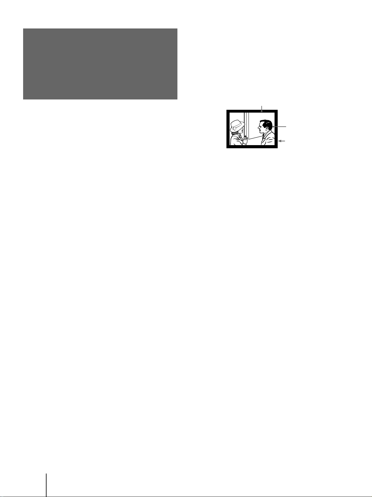
On blanking around the pciture
The monitor displays black masks between the picture
and the screen vessel because the monitor under-scans
to obtain the necessary space on the screen to display
the picture. This is called blanking. Note that the black
masks on each vessel are not uniform.
To adjust the size and position of the picture, see pages
16 and 17.
Blanking
Picture
On safety
• Check that the operating voltage of your unit is
identical with the voltage of your local power
supply.
• One blade of the plug is wider than the other for
safety purposes and will fit into the power outlet
only one way. If you are unable to insert the plug
fully into the outlet, contact your dealer.
• Should any liquid or solid object fall into the
cabinet, unplug the monitor and have it checked by
qualified personnel before operating it further.
• Unplug the monitor from the wall outlet if you are
not going to use it for several days or more. To
disconnect the cord, pull it out by the plug. Never
pull the cord itself.
• The fans inside the monitor continue working for a
while even after the monitor has been turned off.
Do not unplug the monitor from the AC outlet
while the fans are working.
On installation
• To prevent internal heat build-up, do not block the
ventilation openings.
• Do not install the monitor in a hot or humid place,
or in a place subject to excessive dust or mechanical
vibration.
On screen
The screen surface is easily scratched. Do not rub,
touch or tap it with sharp or abrasive objects.
Be especially careful when transporting the monitor.
Screen vessel
On moisture condensation
If the projection monitor is transported directly from a
cold to a warm location, or if the room temperature
has changed suddenly, the picture may be blurred or
show poor color. This is because moisture has
condensed on the lenses inside. If this happens, leave
the power on and let the moisture evaporate before
using the monitor.
On cleaning
• Clean the cabinet of the monitor with a dry soft
cloth. Stubborn stains may be removed with a cloth
slightly dampened with solution of mild soap and
water, then wipe it with a dry soft cloth.
• Do not use any type of solvent such as alcohol,
benzine, thinner or insecticide. Such solvent may
damage the finish of the monitor or erase the
indications on the panel.
• To remove dust from the screen, wipe it gently with
a dry soft cloth.
• Stubborn stains on the screen may be removed with
a soft cloth slightly dampened with solution of mild
soap and water.
• If the picture becomes dark after using the monitor
for a long period of time, it may be necessary to
clean the inside of the monitor. Consult qualified
service personnel.
-GB
4
Page 5
Getting Started
Step 1: Installing
the projection
monitor
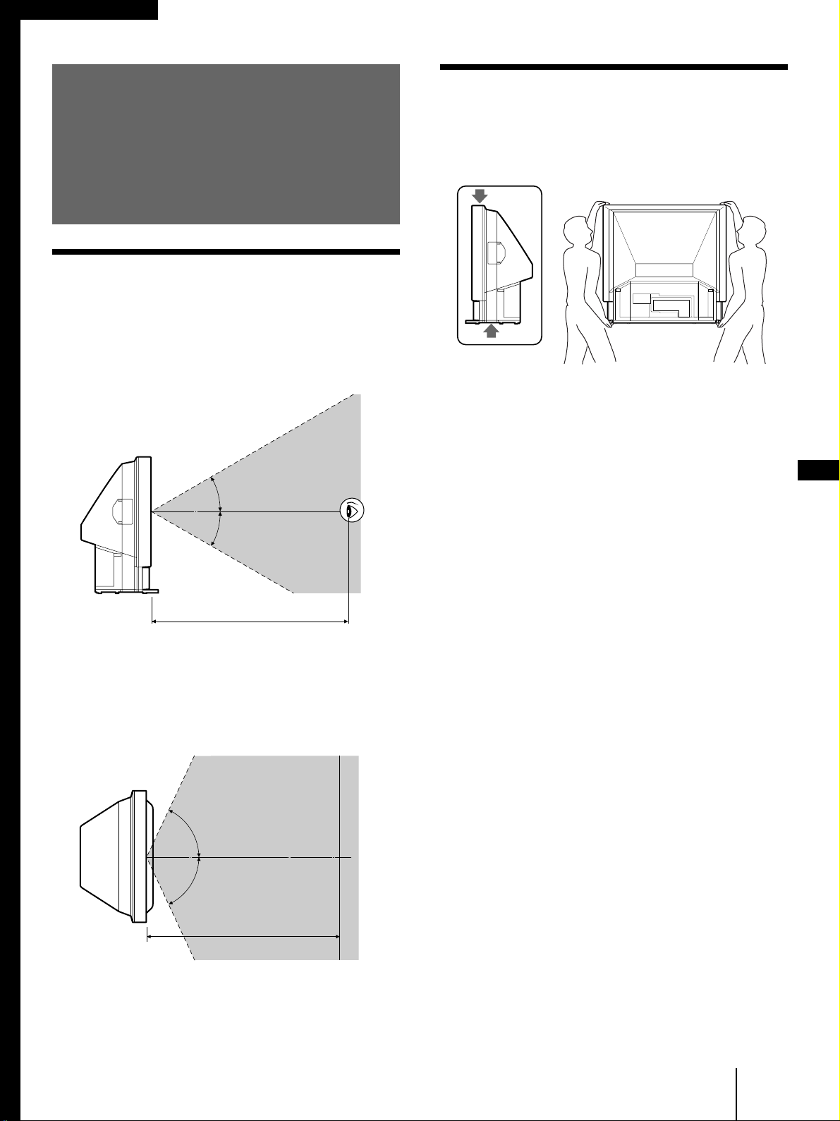
Optimum viewing area
For the best picture quality, install the monitor within
the areas shown below.
Vertical viewing area (side view)
30°
Carrying your monitor
Be sure to grasp only the areas indicated by the arrows
when carrying the monitor, and to use more than two
people.
GB
30°
More than 3.5 m
Horizontal viewing area (top view)
65°
65°
More than 3.5 m
Getting Started
-GB
5
Page 6
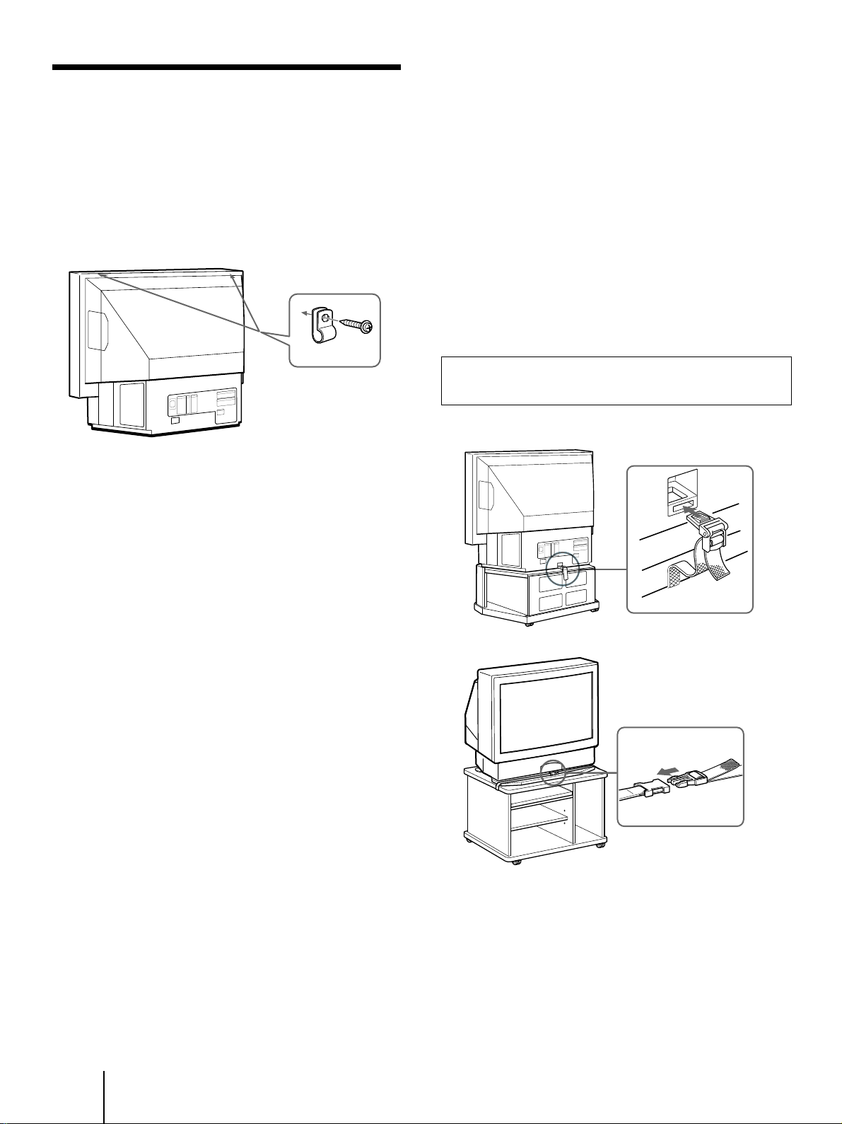
Stabilizing the monitor
For customers in Japan and the U.S.
only
Using the brackets
After setting up, secure the monitor to a wall, etc. with
the supplied brackets.
1 Mount the two supplied brackets with the
screws to the upper rear sides of the
monitor.
Bracket (supplied)
2 Pass a strong cord or a chain through each
bracket mounted in step 1, and then secure
it to a wall or a pillar, etc.
Using the support belts (not supplied)
You can also use the BLT-R10 support belt for the
monitor stand (not supplied) to secure the monitor.
We recommend you use the SU-90 monitor stand with
which the support belts are supplied.
About the SU-90 monitor stand (not supplied)
The dimensions of the stand are 1,050 x 700 x 630 mm
(41 3/8 x 27 5/8 x 24 7/8 inches) (width/height/depth).
Before you purchase this stand, refer to the dimensions
above and check the size of the area where the stand
will be installed.
Customers in Japan should use the stand SU-90T.
Customers in the U.S. should use the stand SU-90U.
Rear
Front
-GB
6
Getting Started
Page 7
Step 2: Hookup
Before making the connection, turn off the power and
disconnect the AC power cords of the monitor and the
equipment to be connected. Refer to the instruction
manual of the equipment you connect.
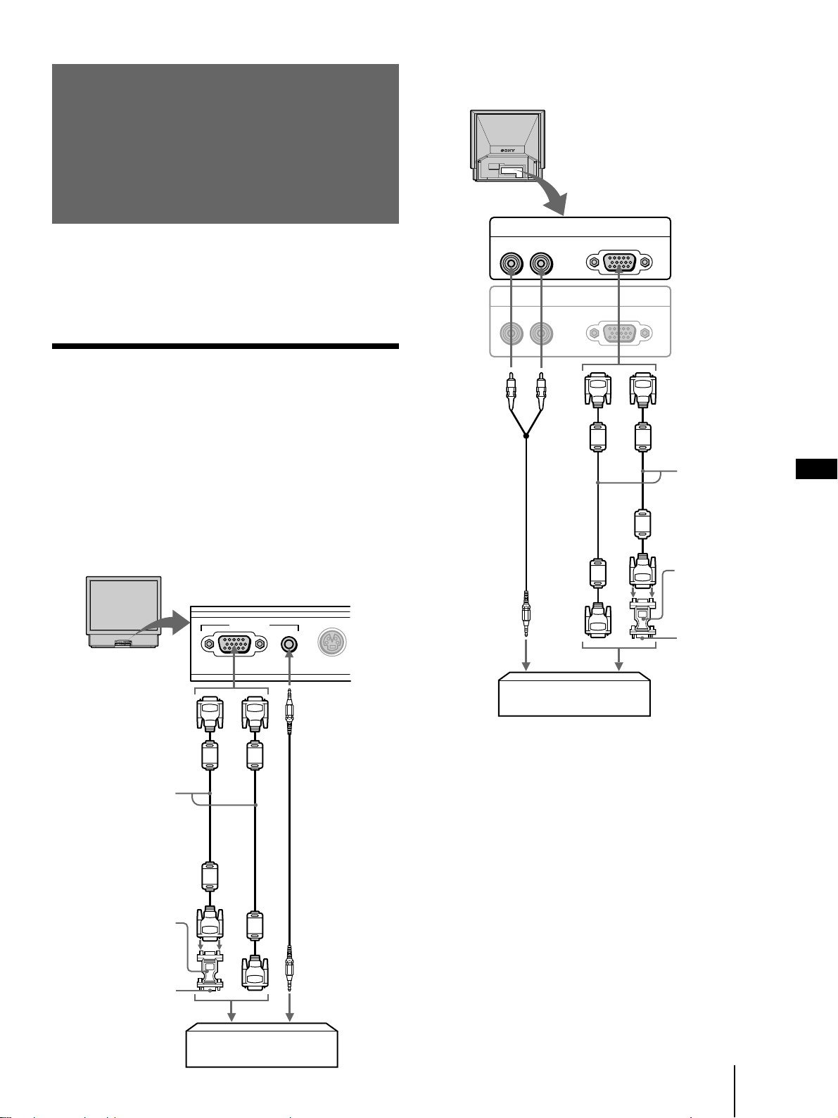
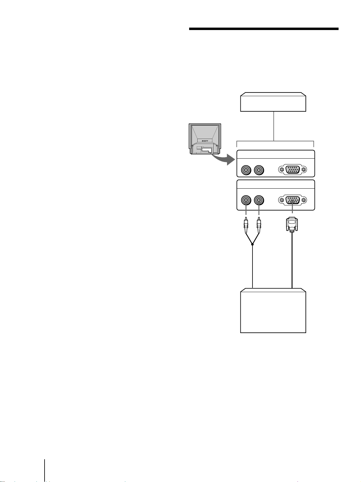
Connecting to an IBM PC/AT or
compatible computer
Connect the RGB 2 IN connector on the front or the
RGB 1 IN connector at the rear of the monitor to the
video output of the computer using the supplied RGB
signal cable (D-sub 15 pin ˜ D-sub 15 pin). Use an
audio connecting cord (not supplied) for the audio
connections.
Using the rear RGB 1 IN connector
Rear of the monitor
RGB 1 IN
RL
RL
Audio connecting
cord (phono plug
× 2 ˜ stereo
miniplug)
(not supplied)
AUDIO
RGB OUT
AUDIO
RGB
RGB
or
RGB signal cable
(supplied)
GB
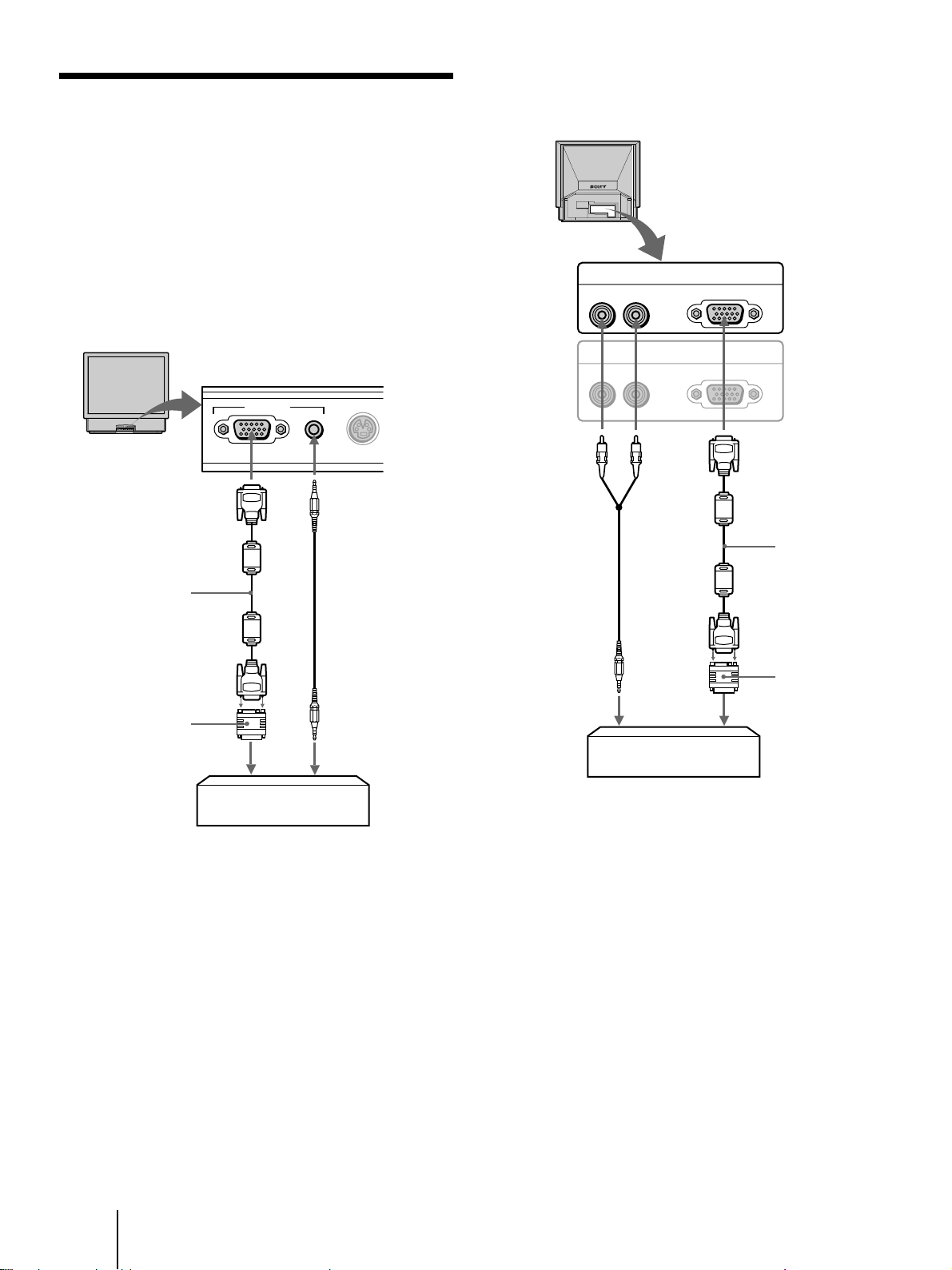
Using the front RGB 2 IN connector
Front of the monitor
RGB 2 IN
RGB
RGB signal cable
(supplied)
or
HD15–HD15 adaptor
(supplied)*
Male side
(without the No.9 pin)
to video output
S VIDEO
AUDIO
Audio connecting
cord
(stereo miniplug ˜
stereo miniplug)
(not supplied)
to audio output
HD15–HD15 adaptor
(supplied)*
Male side (without
the No.9 pin)
to audio output
IBM PC/AT or compatible
computer
to video output
* The HD15–HD15 adaptor (supplied) may be needed for some
models. The male side (without the No. 9 pin) of the adaptor
should be connected to the computer.
For customers using the supplied HD15–HD15
adaptor
This monitor uses a No. 9 pin in the video signal
connector for DDC1 and DDC2B compatibility.
Some PC systems which are not compatible with either
DDC1 or DDC2B may not accept the No. 9 pin. If you
are not sure whether your PC system accepts the No. 9
pin or not, use the HD15 (Female) – HD15 (Male
without the No. 9 pin) adapter (supplied).
IBM PC/AT or compatible
computer
Getting Started
-GB
7
Page 8
Connecting to a Macintosh or
RGB
RGB OUT
RGB 1 IN
RL
AUDIO
RL
AUDIO
RGB
compatible computer
Connect the RGB 2 IN connector on the front or the
RGB 1 IN connector at the rear of the monitor to the
video output of the computer using the supplied RGB
signal cable (D-sub 15 pin ˜ D-sub 15 pin) and the
supplied Macintosh adaptor. Use an audio connecting
cord (not supplied) for the audio connections.
Using the front RGB 2 IN connector
Front of the monitor
RGB 2 IN
Using the rear RGB 1 IN connector
Rear of the monitor
RGB signal cable
(supplied)
Macintosh adaptor
(supplied)
to video output
RGB AUDIO
Macintosh or compatible
computer
S VIDEO
Audio connecting cord
(stereo miniplug ˜
stereo miniplug)
(not supplied)
to audio output
Audio connecting
cord
(phono plug × 2 ˜
stereo miniplug)
(not supplied)
to audio output
Macintosh or compatible
computer
RGB signal cable
(supplied)
Macintosh adaptor
(supplied)
to video output
About the supplied Macintosh adaptor
The supplied Macintosh adaptor is compatible with
Macintosh LC, Performa, Quadra and Power
Macintosh series computers. Macintosh II series and
some version of PowerBook models may need an
another adaptor with micro switches (not supplied).
-GB
8
Getting Started
Page 9
Preset and user modes
The monitor automatically detects input signals with a
horizontal scanning frequency between 24.8 and 85.0
kHz and a vertical scanning frequency between 50 and
85 Hz. However, it is recommended that a signal with a
vertical scanning frequency of 60 Hz is used since the
screen may go blank for a few seconds whenever a
signal other than 60 Hz is input to the monitor.
The monitor is capable of a display resolution of up to
1,024 × 768 dots. When a signal with a higher resolution
is input, it will be processed to display the image at
1,024 × 768 dots.
User modes
When using a video mode that is not one of the preset
modes, some fine tuning may be required to optimize
the display to your preference. Simply adjust the
monitor according to the adjustments instructions on
pages 16 through 18. The adjustments will be stored
automatically and recalled whenever that mode is
used.
Recommended horizontal timing
conditions
Horizontal sync width should be more than 1.0 µsec.
Horizontal blanking width should be more than 3.6
µsec.
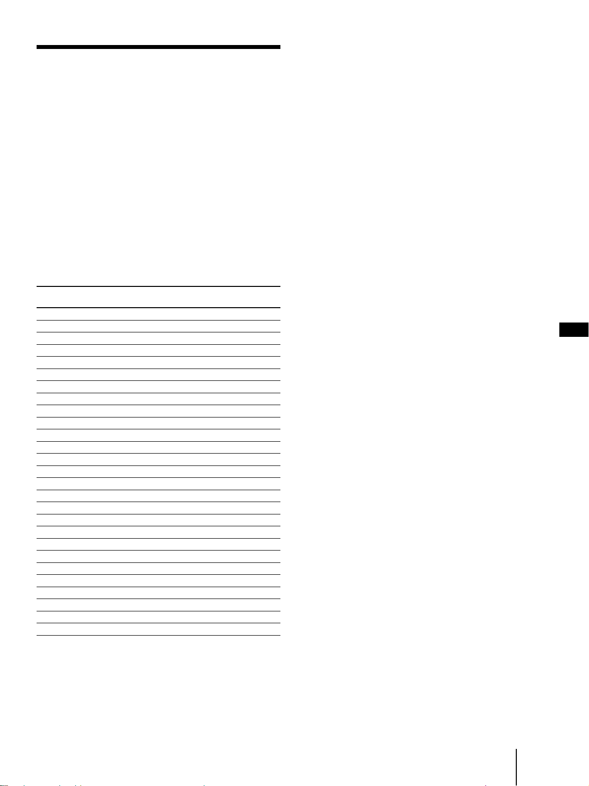
Preset modes
The monitor has the factory preset modes for the most
popular industry standards as shown below.
No.
Resolution
(dots × lines)
1 640 × 350* 31.469 70.086 VGA mode 1 H-pos V-neg
2 640 × 400* 24.823 56.416 PC-9801 Normal H-neg V-neg
3 640 × 480 31.469 59.940 VGA mode 3 H-neg V-neg
4 640 × 480 35.000 66.667 Macintosh 13" H-neg V-neg
5 640 × 480 37.861 72.809 VGA VESA 72 Hz H-neg V-neg
6 640 × 480 37.500 75.000 VGA VESA 75 Hz H-neg V-neg
7 640 × 480 43.269 85.008 VGA VESA 85 Hz H-neg V-neg
8 720 × 400 31.469 70.087 VGA mode 2 H-neg V-pos
9 720 × 400 37.927 85.039 VGA VESA 85 Hz H-neg V-pos
10 800 × 600 35.156 56.250 SVGA VESA 56 Hz H-pos V-pos
11 800 × 600 37.879 60.317 SVGA VESA 60 Hz H-pos V-pos
12 800 × 600 48.077 72.188 SVGA VESA 72 Hz H-pos V-pos
13 800 × 600 46.875 75.000 SVGA VESA 75 Hz H-pos V-pos
14 800 × 600 53.674 85.061 SVGA VESA 85 Hz H-pos V-pos
15 832 × 624 49.727 74.553 Macintosh 16" H-neg V-neg
16 1024 × 768 35.522 43.479 XGA VESA 43 Hz H-pos V-pos
17 1024 × 768 48.363 60.004 XGA VESA 60 Hz H-neg V-neg
18 1024 × 768 56.476 70.069 XGA VESA 70 Hz H-neg V-neg
19 1024 × 768 60.023 75.029 XGA VESA 75 Hz H-pos V-pos
20 1024 × 768 60.241 74.927 Macintosh 19" H-neg V-neg
21 1024 × 768 68.677 84.997 XGA VESA 85 Hz H-pos V-pos
22 1152 × 864 67.500 75.000 SXGA VESA 75 Hz H-pos V-pos
23 1152 × 870 68.681 75.060 Macintosh 21" H-neg V-neg
24 1280 × 960 60.000 60.000 SXGA VESA 60 Hz H-pos V-pos
25 1280 ×1024 46.433 43.436 SXGA VESA 43 Hz H-pos V-pos
26 1280 ×1024 63.981 60.020 SXGA VESA 60 Hz H-pos V-pos
27 1280 ×1024 79.976 75.025 SXGA VESA 75 Hz H-pos V-pos
* The monitor projects the picture in 4:3 aspect ratio.
fH fV Graphics Sync
(kHz) (Hz) mode
If the frequency range of an input
signal is not acceptable for the
monitor
“OUT OF SCAN RANGE” appears on the screen.
The monitor does not accept an interlace mode
signal that is not a preset mode signal. Furthermore,
if you input a signal other than a preset mode signal
with a dot clock of more than 140 MHz, the picture
may be distorted.
Plug & Play
This monitor complies with the DDCTM1 and DDC2B
which are the Display Data Channel (DDC) standards
of VESA.
When a DDC1 host system is connected, the monitor
synchronizes with the V. CLK in accordance with the
VESA standards and outputs the EDID (Extended
Display Identification Data) to the data line.
When a DDC2B host system is connected, the monitor
automatically switches to each communication.
GB
(continued)
Getting Started
-GB
9
Page 10
For customers using Windows 95/98
To maximize the potential of your monitor, install the
new model information file from the supplied
Windows Monitor Information Disk onto your
computer.
This monitor complies with the “VESA DDC” Plug &
Play standard. If your computer/graphic board
complies with DDC, select “Plug & Play Monitor
(VESA DDC)” or this monitor’s model name as the
monitor type in the “Control Panel” of Windows 95/
98. If your computer/graphic board has difficulty
communicating with this monitor, load the Windows
Monitor Information Disk and select this monitor’s
model name as the monitor type.
Connecting another monitor
This monitor outputs the signal input from the RGB 1
IN or RGB 2 IN connector through the RGB OUT
connector, and can display the picture on another
monitor.
See pages 7 and 8 for connecting a computer.
Computer
Rear of the monitor
See pages 7 and 8 for
connecting a
to RGB IN
computer.
For customers using Windows NT4.0
Monitor setup in Windows NT4.0 is different from
Windows 95/98 and does not involve the selection of
monitor type. Refer to the Windows NT4.0 instruction
manual for further details on adjusting the resolution,
refresh rate, and number of colors.
Adjusting the monitor’s resolution and
color number
Adjust the monitor‘s resolution and color number by
referring to your computer’s instruction manual. The
color number may vary according to your computer or
video board. The color palette setting and the actual
number of colors are as follows:
• High Color (16 bit) n 65,536 colors
• True Color (24 bit) n about 16.77 million colors
In true color mode (24 bit), speed may be slower.
RGB 1 IN
AUDIO
RL
RGB OUT
AUDIO
RL
to AUDIO R/L to RGB OUT
to audio input
to RGB input
Another monitor
RGB
RGB
Connection varies
according to the
type of RGB input
connector on the
other monitor.
For details, see the
operating
instructions
supplied with the
monitor.
10
-GB
Getting Started
Note
When connecting another monitor, the picture’s centering may
change. If this happens, adjust the centering of the second
monitor.
Page 11
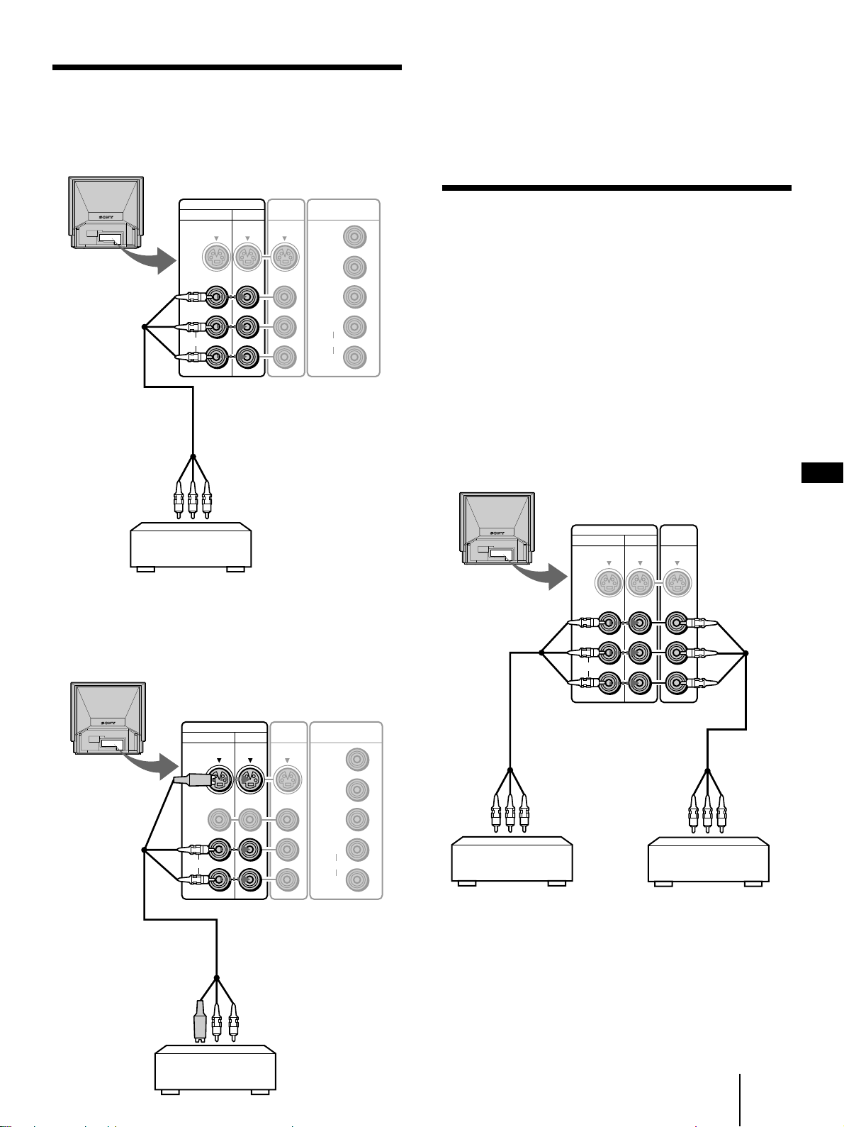
Connecting to video equipment
To a VCR not equipped with an S video
connector
Rear of the monitor
Notes
• You can also use the S VIDEO connector on the VIDEO 2 IN
panel on the front of the monitor.
• When you connect the cable to both the VIDEO jack and the S
VIDEO connector, the picture from the S VIDEO connector is
displayed on the monitor screen.
to VIDEO 1 IN or
VIDEO 3 IN
VMC-810S/820S
(not supplied)
VIDEO IN VIDEO
1 3
S VIDEO
VIDEO
L
AUDIO
R
to video/audio outputs
VCR
OUT
COMPONENT IN
Y
PB/CB/B-Y
PR/CR/R-Y
L
AUDIO
R
You can also use the VIDEO 2 IN jacks on the front of
the monitor for the video/audio connections.
Connecting two VCRs for editing
The monitor outputs the signal input from the VIDEO 1
IN, VIDEO 2 IN or VIDEO 3 IN jacks through the
VIDEO OUT jacks. With two VCRs connected to the
VIDEO IN and VIDEO OUT jacks, you can edit a tape.
Notes
• Signals input from the RGB 1 IN, RGB 2 IN and COMPONENT
IN connectors are not output through the VIDEO OUT jacks.
• Do not connect both the VIDEO IN and VIDEO OUT jacks on
this monitor simultaneously to the video/audio output and
input jacks on a single VCR.
• If no signal is input to the S VIDEO connector on any of the
VIDEO 1, 2 and 3 IN panels, the S VIDEO connector on the
VIDEO OUT panel does not output a signal.
Rear of the monitor
VIDEO IN VIDEO
to VIDEO 1 IN
or VIDEO 3 IN
1 3
S VIDEO
VIDEO
OUT
to VIDEO OUT
GB
To an S video equipped VCR
Rear of the monitor
VIDEO IN VIDEO
to VIDEO 1 IN or
VIDEO 3 IN
YC-810S
(not supplied)
1 3
S VIDEO
VIDEO
L
AUDIO
R
OUT
to S video/audio outputs
COMPONENT IN
Y
PB/CB/B-Y
PR/CR/R-Y
L
AUDIO
R
VMC-810S/820S
(not supplied)
to video/audio
outputs
VCR for playback
L
AUDIO
R
VMC-810S/820S
(not supplied)
to video/
audio
inputs
VCR for recording
VCR
Getting Started
11
-GB
Page 12
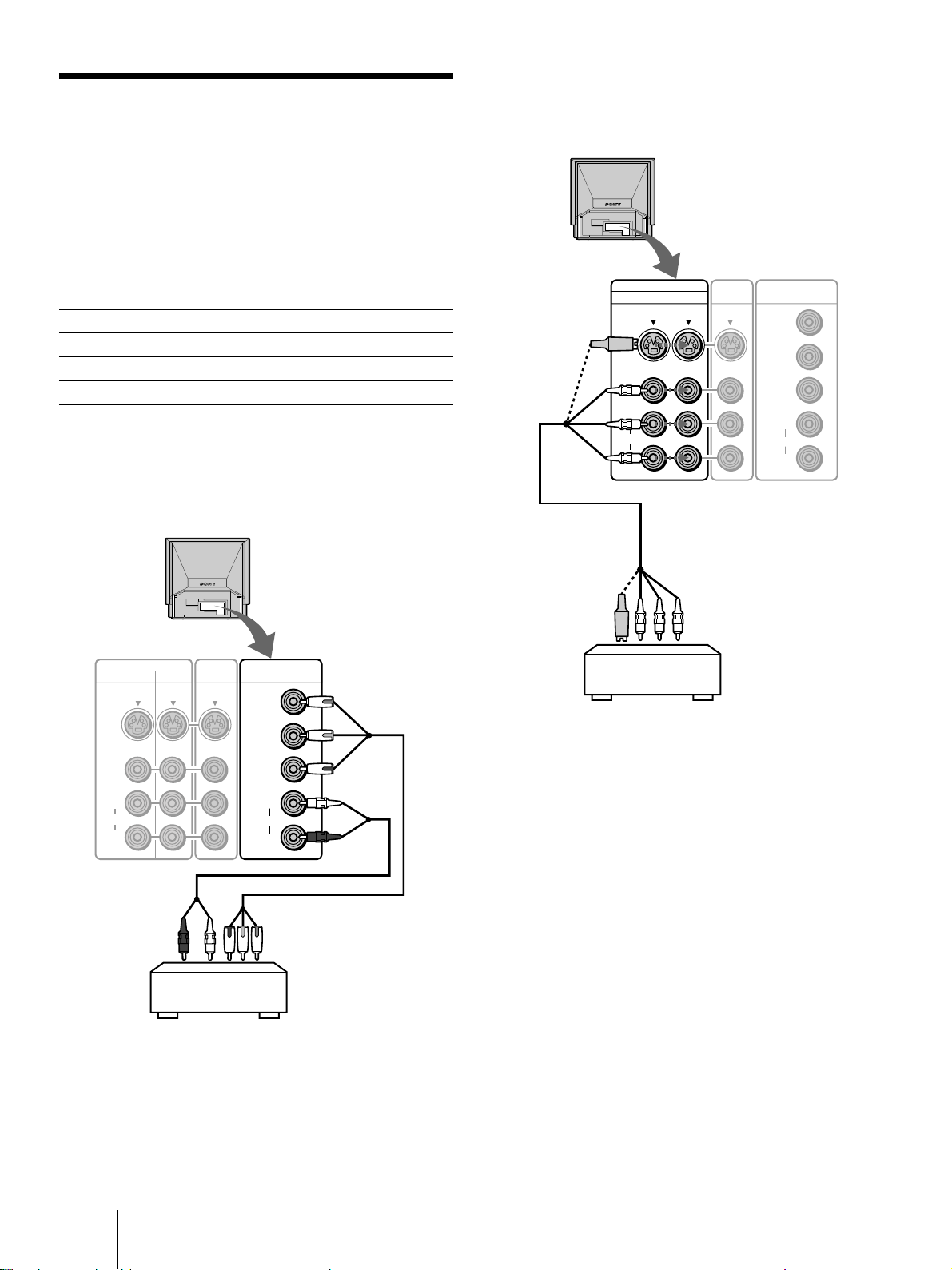
Connecting a DVD Player
Connecting a DVD player without
component video output connectors
If your DVD player has component video output
connectors*, connect them to the COMPONENT IN (Y,
PB/CB/B-Y and PR/CR/R-Y) connectors at the rear of
the monitor for higher quality picture. For details, see
the instructions supplied with the DVD player.
* Some DVD player terminals may be labeled or
colored differently. If so, connect them as follows:
Connect (on the monitor) To (on a DVD player)
Y (green) Y
PB/CB/B-Y (blue) PB, CB, Cb or B-Y
PR/CR/R-Y (red) PR, CR, Cr or R-Y
Connecting a DVD player with
component video output connectors
Rear of the monitor
Rear of the monitor
to VIDEO 1 IN or
VIDEO 3 IN
VIDEO IN VIDEO
1 3
S VIDEO
VIDEO
L
AUDIO
R
VMC-810S/820S
(not supplied)
OUT
COMPONENT IN
Y
PB/CB/B-Y
PR/CR/R-Y
L
AUDIO
R
VIDEO IN VIDEO
1 3
S VIDEO
VIDEO
L
AUDIO
R
to audio
outputs
OUT
DVD player
COMPONENT IN
Y
PB/CB/B-Y
PR/CR/R-Y
L
AUDIO
R
VMC-10HG (not supplied)
to component video outputs
to COMPONENT IN
to audio/video
outputs
DVD player
Note
If you have an S video equipped DVD player, use the S video
connecting cord (not supplied) instead of the yellow video
connecting cord to obtain a higher quality picture.
12
-GB
Getting Started
Page 13
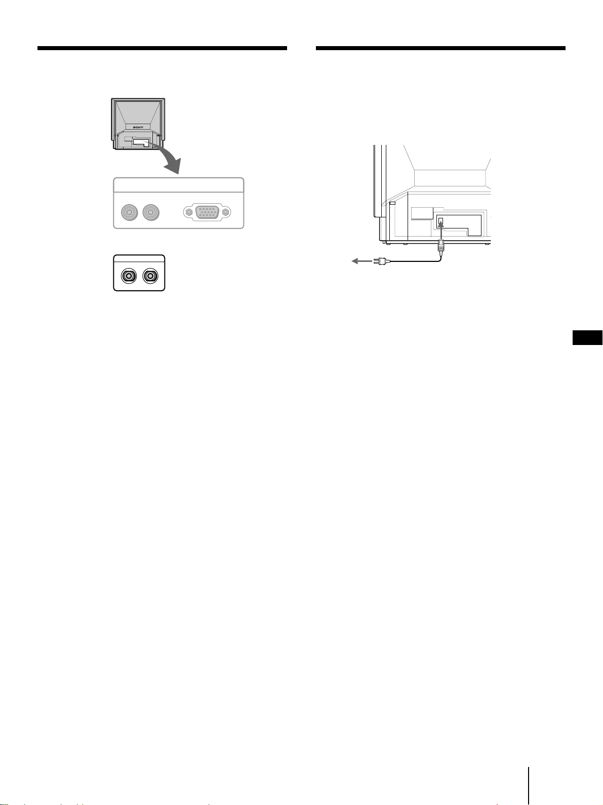
Using the CONTROL S jacks
Connecting the AC power cord
Rear of the monitor
RGB OUT
AUDIO
RL
CONTROL S
IN OUT
RGB
To use the CONTROL S IN jack
You can control this monitor from other equipment by
connecting the CONTROL S IN jack to the CONTROL
S output jack on other equipment. In this case, the
remote control detector on this monitor does not
function.
Connect one end of the supplied power cord to the
monitor’s AC IN socket and the other end to a wall AC
outlet.
Rear of the monitor
to an AC outlet
AC power cord
(supplied)
to AC IN
GB
To use the CONTROL S OUT jack
You can operate this monitor with the remote control
supplied with other equipment by connecting the
CONTROL S OUT jack to the CONTROL S input jack
on other equipment.
Getting Started
13
-GB
Page 14
Step 3: Setting up
MENU ENTER
Changing the menu
the remote
control
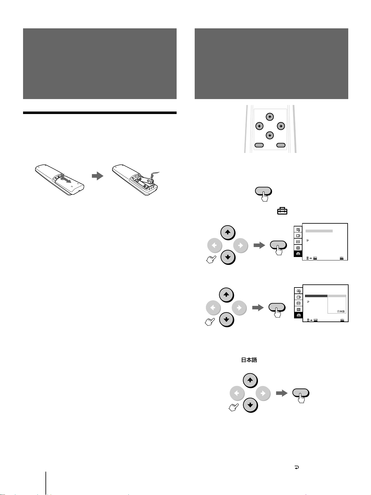
Inserting batteries
Insert two AA (R6) size batteries (supplied) by
matching the + and – on the battery to the diagram
inside the battery compartment.
Notes
• If the remote control does not operate properly, the batteries
may be worn out. When replacing batteries, replace both of
them with new ones.
• Do not mix old batteries with new ones or mix different types
of batteries together.
• If the electrolyte inside the battery should leak, wipe the
contaminated area of the battery compartment with a cloth and
replace the old batteries with new ones. To prevent the
electrolyte from leaking, remove the batteries when you don‘t
plan to use the remote control for a long period of time.
• Do not handle the remote control roughly. Do not drop it, step
on it, or let it get wet.
• Do not place the remote control in direct sunlight, near a
heater, or where the humidity is high.
language
If you prefer Spanish, French, German, Italian or
Japanese to English, you can change the menu language.
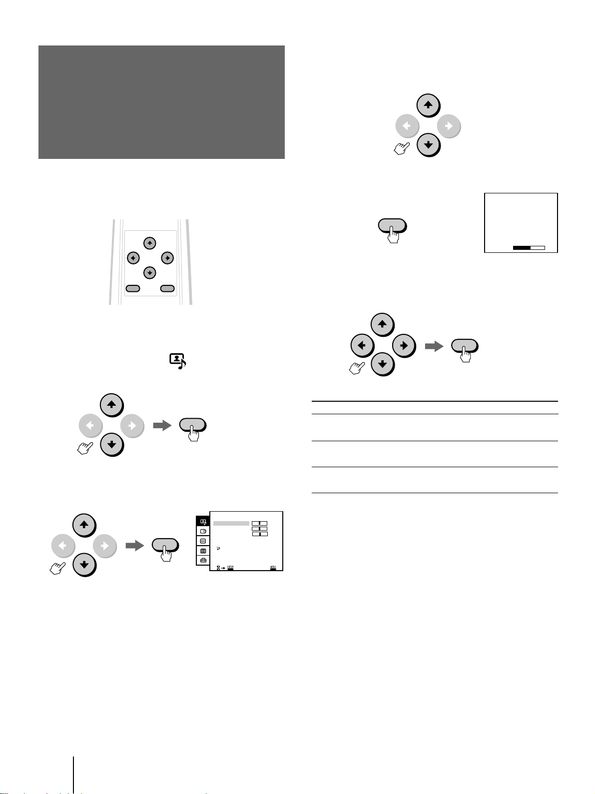
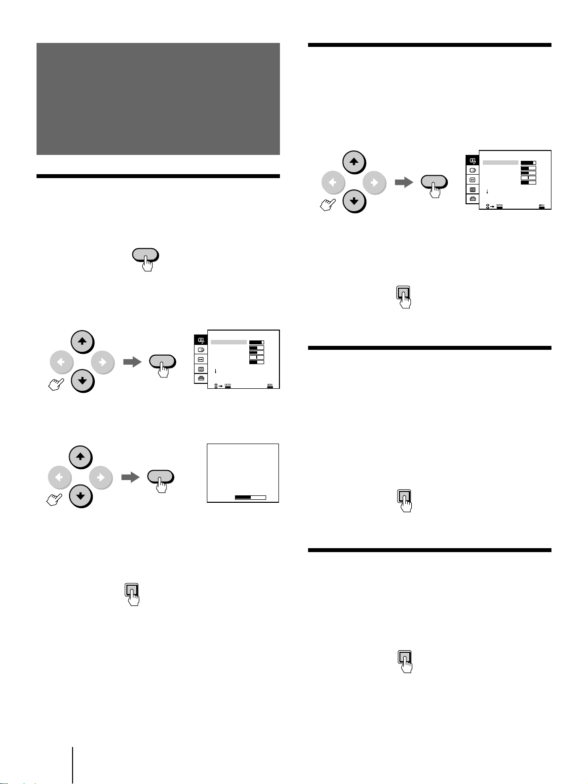
1 Press MENU.
2 Press v or V to select “ (OPTION),” and
press ENTER.
3 Press v or V to select LANGUAGE, and press
ENTER.
MENU
ENTER
ENTER
OPTION
AUTO SHUT OFF:
LANGUAGE:
COLOR SYSTEM:
OPTION
AUTO SHUT OFF:
LANGUAGE:
COLOR SYS
FRANÇAIS
OFF
ENGLISH
AUTO
EXIT
OFF
ENGLISH
ESPAÑOL
DEUTSCH
ITALIANO
-GB
14
Getting Started
EXI T
4 Press v or V to select your favorite language,
ENGLISH, FRANÇAIS (French), DEUTSCH
(German), ESPAÑOL (Spanish), ITALIANO
(Italian) or (Japanese), and press
ENTER.
ENTER
5 Press MENU to return to the original screen.
Notes
• You can operate the menu using the √/◊/ı/∫ and the ENTER
buttons inside the drop-down panel on the front of the monitor.
• You cannot use the AUTO SHUT OFF function for the input
from VIDEO 1/2/3 IN and COMPONENT IN. (See page 24.)
• To get back to the previous menu, select
ENTER.
with v or V and press
Page 15
Operations
COMPONENT
Projecting the
2 Turn on the power of the connected
equipment.
picture
RGB
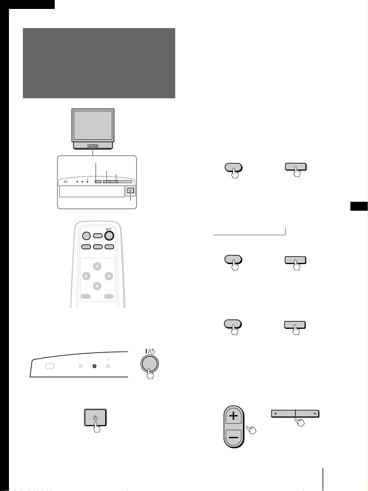
LAMP RGB
STANDBY
u (power) switch
MUTING
DISPLAY
COMPONENT
VIDEO
COMPONENT
VIDEO –VOLUME+
3 Press RGB, VIDEO or COMPONENT on the
remote control or the monitor to select the
input you want to watch.
The selected input indication is displayed on the
screen.
To watch a computer picture input from the
RGB 1/2 IN connector
Each time you press RGB, the display changes as
follows:
RGB 1 ˜ RGB 2
Remote control
RGB
or
To watch a video picture input from the
VIDEO 1/2/3 IN jacks
Each time your press VIDEO, the display changes
as follows:
VIDEO 1 n VIDEO 2 n VIDEO 3
N
Monitor
RGB
GB
COMPONENT
VIDEO
MENU ENTER
RGB
1 If the STANDBY indicator on the front of
the monitor is lit in orange, press 1 /u
(power) on the remote control to turn on
the power.
LAMP
STANDBY
Press the u (power) switch on the monitor if the
STANDBY indicator is not lit.
Remote control Monitor
VIDEO
or
VIDEO
To watch a picture of a DVD player input
from the COMPONENT IN jacks
Press COMPONENT.
Remote control Monitor
COMPONENT
or
The input signal indication will automatically
disappear.
4 Press VOL +/– (VOLUME +/–) to adjust the
volume.
Remote control Monitor
VOL
or
–VOLUME+
The green u (power) indicator flashes, then lights
up.
(continued)
Operations
15
-GB
Page 16
To turn off the monitor
MENU ENTER
Press 1/u on the remote control. The monitor enters
standby mode and the STANDBY indicator lights up.
To turn off the main power, press u switch on the
monitor.
Note
To protect the lamp, the picture and sound will not turn on
immediately if you try to turn on the power more than 5 seconds
after the power has been turned off. If you turn the monitor back
on within about 5 seconds after power-off, the picture and sound
will reappear immediately.
Muting the sound
Press MUTING on the remote control.
“MUTING” appears on the screen.
To restore the sound, press MUTING again, or press
VOL+.
Displaying on-screen information
Press DISPLAY on the remote control to display the
following information on the screen.
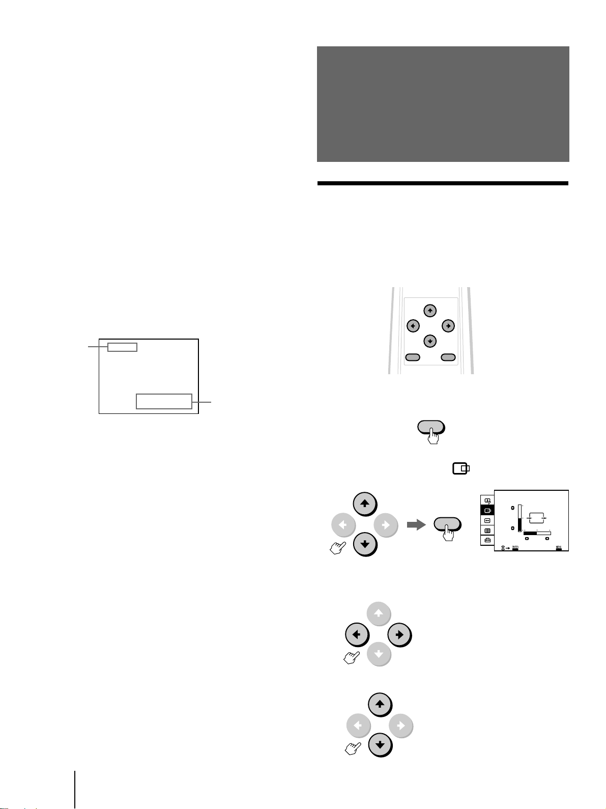
Adjusting the
computer picture
Adjusting the position (CENTER)
After projecting the picture from a computer, you may
need to adjust the position of the picture to fit the
monitor screen. You can also move the picture as you
like. The setting is only for the input signal displayed
on the screen.
Current input
signal
RGB 1
fH: 37.5kHz
fV: 75Hz
*fH: Horizontal frequency
fV: Vertical frequency
“OUT OF SCAN RANGE” appears if the scanning
frequency range is not within the acceptable
limits. (See page 9.)
Current input signal
frequency when
the RGB signal* is
input
To make the on-screen information disappear, press
DISPLAY again.
1 Press MENU.
MENU
2 Press v or V to select “ (CENTER),” and
press ENTER.
CENTER
ENTER
EXI T
3 Press v, V, B or b to adjust the position.
For horizontal adjustment press B or b.
b: to move the picture right
B: to move the picture left
-GB
16
For vertical adjustment press v or V.
V: to move the picture up
v: to move the picture down
Operations
Page 17
The CENTER adjustment screen automatically
disappears after about 80 seconds if you do not press
any button. You can also erase the CENTER adjustment
screen by pressing MENU.
To reset to the factory preset setting
Press RESET on the monitor while the CENTER
adjustment screen is displayed. For details, see page 26.
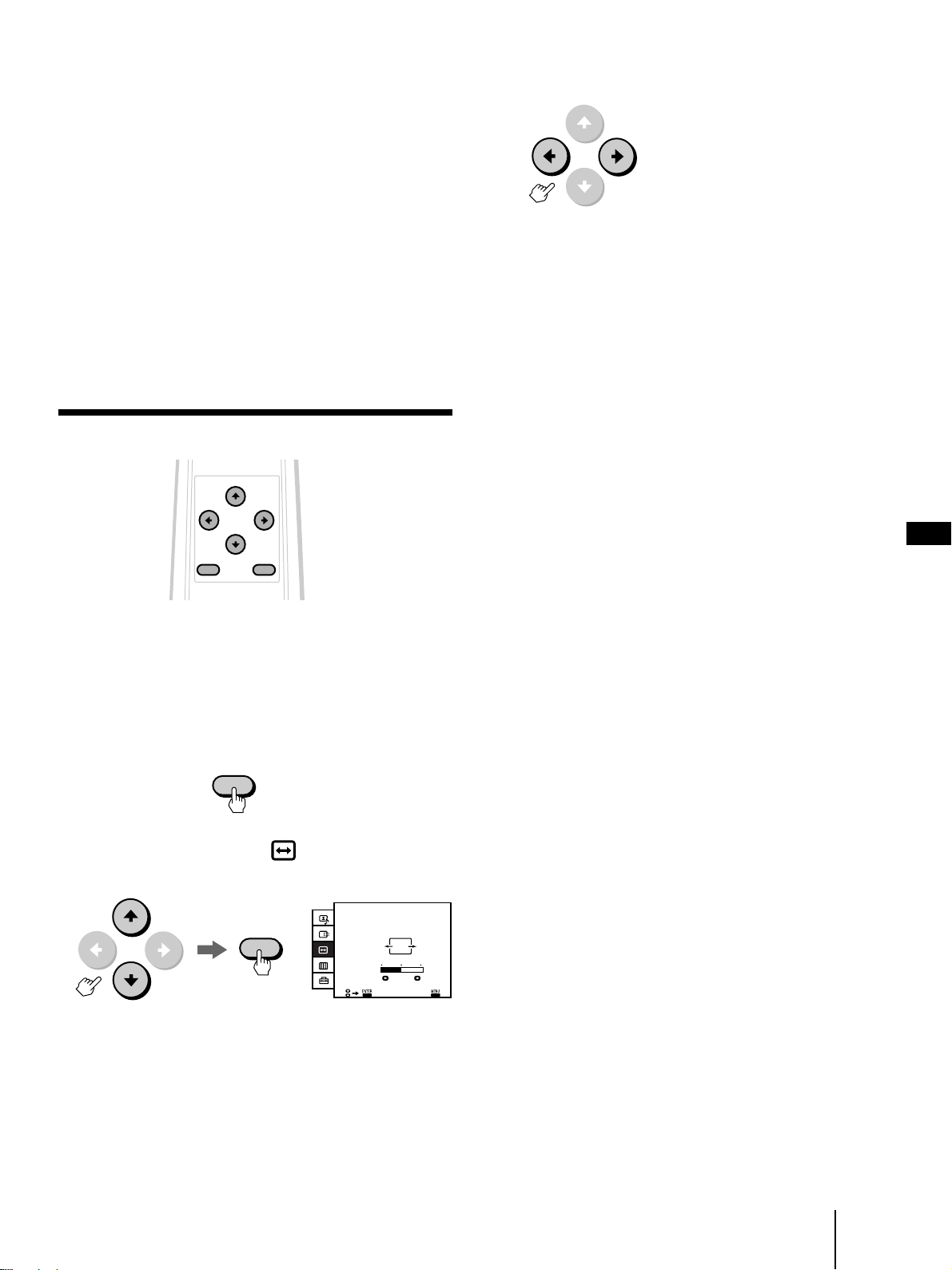
3 Press B or b to adjust the picture size.
b: to increase horizontal size
B: to decrease horizontal size
Notes
• You cannot use this function for the input from VIDEO 1/2/3
IN and COMPONENT IN.
• You can operate the menu using the √/◊/ı/∫ and the ENTER
buttons inside the drop-down panel on the front of the
monitor.
Adjusting the picture size (SIZE)
MENU ENTER
After projecting the picture from a computer, you may
need to adjust the picture size to fit the monitor screen.
The setting is only for the input signal displayed on the
screen.
The SIZE adjustment screen automatically disappears
after about 80 seconds if you do not press any button.
You can also erase the SIZE adjustment screen by
pressing MENU again.
To reset to the factory preset setting
Press RESET on the monitor while the SIZE adjustment
screen is displayed. For details, see page 26.
Notes
• If a signal with resolution of 640 × 350, 640 × 400 or 720 × 400,
or Wide Resolution signal is input, the picture will be enlarged
to fill the screen but will appear lengthened vertically.
• You cannot use this function for the input from VIDEO 1/2/3
IN and COMPONENT IN.
• You can operate the menu using the √/◊/ı/∫ and the ENTER
buttons inside the drop-down panel on the front of the
monitor.
GB
1 Press MENU.
MENU
2 Press v or V to select “ (SIZE),” and press
ENTER.
SIZE
ENTER
EXI T
Operations
17
-GB
Page 18
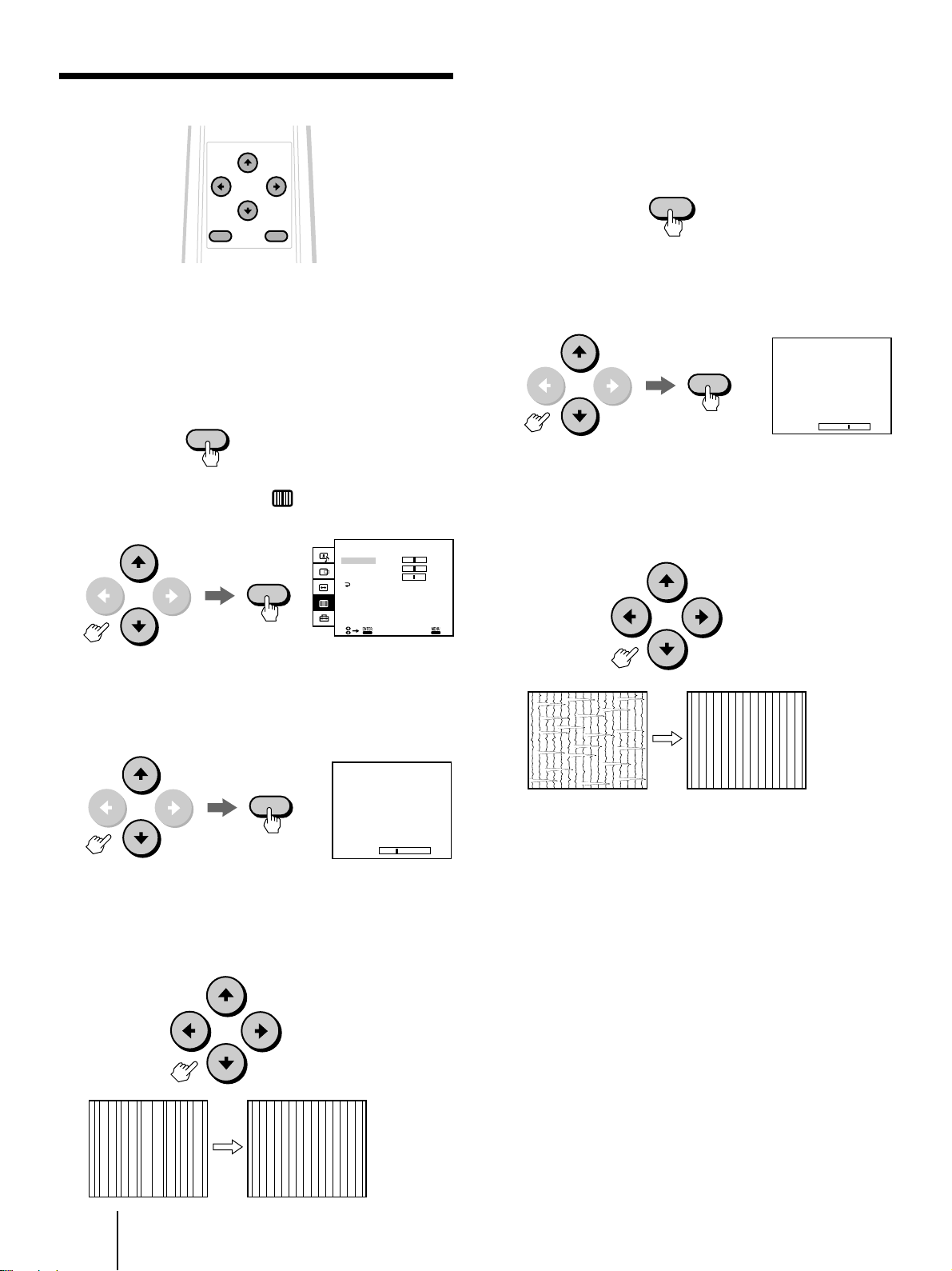
Eliminating flickering or blurring (DOT
ADJUST)
MENU ENTER
If a part of the screen is flickering or blurring, adjust
PITCH and PHASE in the DOT ADJUST menu.
1 Load the Utility Disk (supplied) into your
computer.
2 Press MENU.
MENU
3 Press v or V to select “ (DOT ADJUST),”
and press ENTER.
DOT ADJUST
PHASE
PITCH
ENTER
TIMING
YES
6 Press ENTER.
The DOT ADJUST menu appears.
If notches in the vertical lines or horizontal noise is
observed over the entire screen, adjust PHASE in
the next step.
ENTER
7 Press v or V to select PHASE, and press
ENTER.
The PHASE adjustment screen appears.
ENTER
PHASE
7
8 Press v, V, B or b until the screen becomes
uniform.
Adjust to diminish the notches in the vertical lines
or the horizontal noise on the picture.
7
0
4 Press v or V to select PITCH, and press
ENTER.
The PITCH adjustment screen appears.
ENTER
PITCH
5 Press v, V, B or b until the lines on the
screen become uniform.
Adjust the vertical lines on the screen so that they
are evenly spaced.
EXI T
Using the Utility Disk
– 6
The supplied Utility Disk contains test patterns for
PITCH and PHASE adjustments. These test patterns
will help you confirm that your adjustments are
correct.
If TIMING is set to NO in the DOT ADJUST menu
1 Press v or V to select TIMING, and press ENTER.
The TIMING adjustment screen appears.
2 Press v, V, B or b until TIMING is set to YES.
The PITCH, PHASE or TIMING adjustment screen
automatically disappears after about 80 seconds if you
do not press any button.
You can also erase the screen by pressing MENU again.
18
-GB
Note
You cannot use this function for the input from VIDEO 1/2/3 IN
and COMPONENT IN.
Operations
Page 19
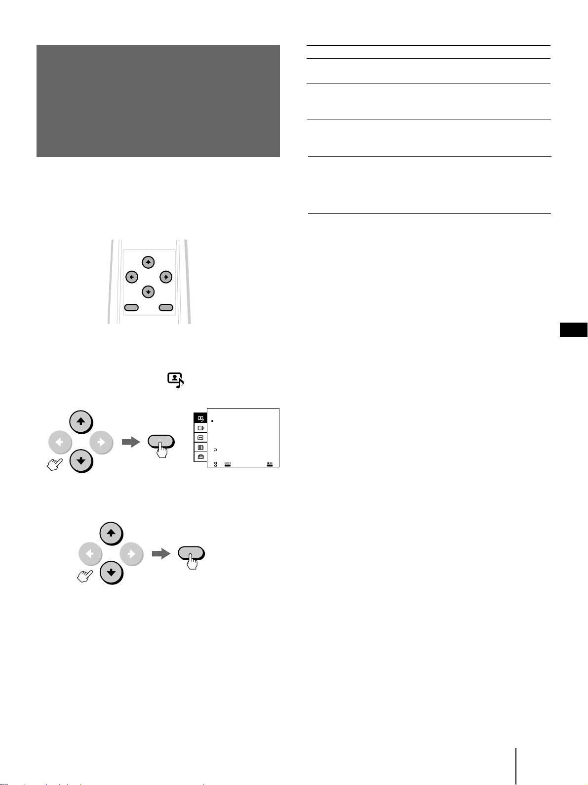
Selecting the preset
picture viewing
mode
The video/audio mode feature allows you to choose
four different modes of picture/sound settings. Choose
the one that best suits the type of program that you
want to watch.
MENU ENTER
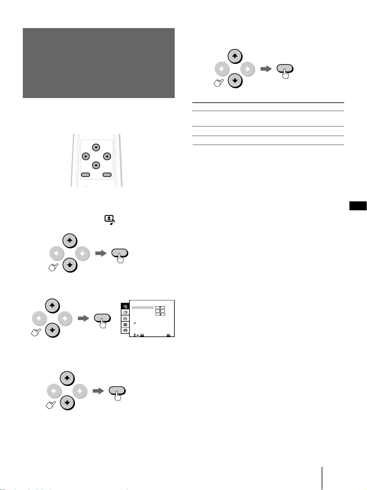
1 Press MENU.
Choose
GRAPHICS
TEXT
MOVIE
AV MEMORY
* COLOR, HUE and H WHITE cannot be adjusted.
To
Watch a picture with
a wide variety of colors.
Watch a picture with
lots of letters or
characters.
Watch a movie using a
computer, video, laser
disk, etc.
Adjust the quality of the
picture/sound to suit
your taste. (For details,
see pages 20 through
22.)
Applicable signal
RGB, video and
component
RGB only
RGB, video and
component
RGB*, video and
component
4 Press MENU to return to the original screen.
To reset to the factory preset setting
See page 26.
Note
You cannot adjust the settings in modes other than AV
MEMORY.
GB
2 Press v or V to select “ (VIDEO/AUDIO),”
and press ENTER.
VIDEO/AUDIO
GRAPHICS
•TEXT
ENTER
•MOVIE
•AV MEMORY
VIDEO ADJUST
AUDIO ADJUST
EXI T
3 Press v or V to select the desired item, and
press ENTER.
ENTER
Operations
19
-GB
Page 20
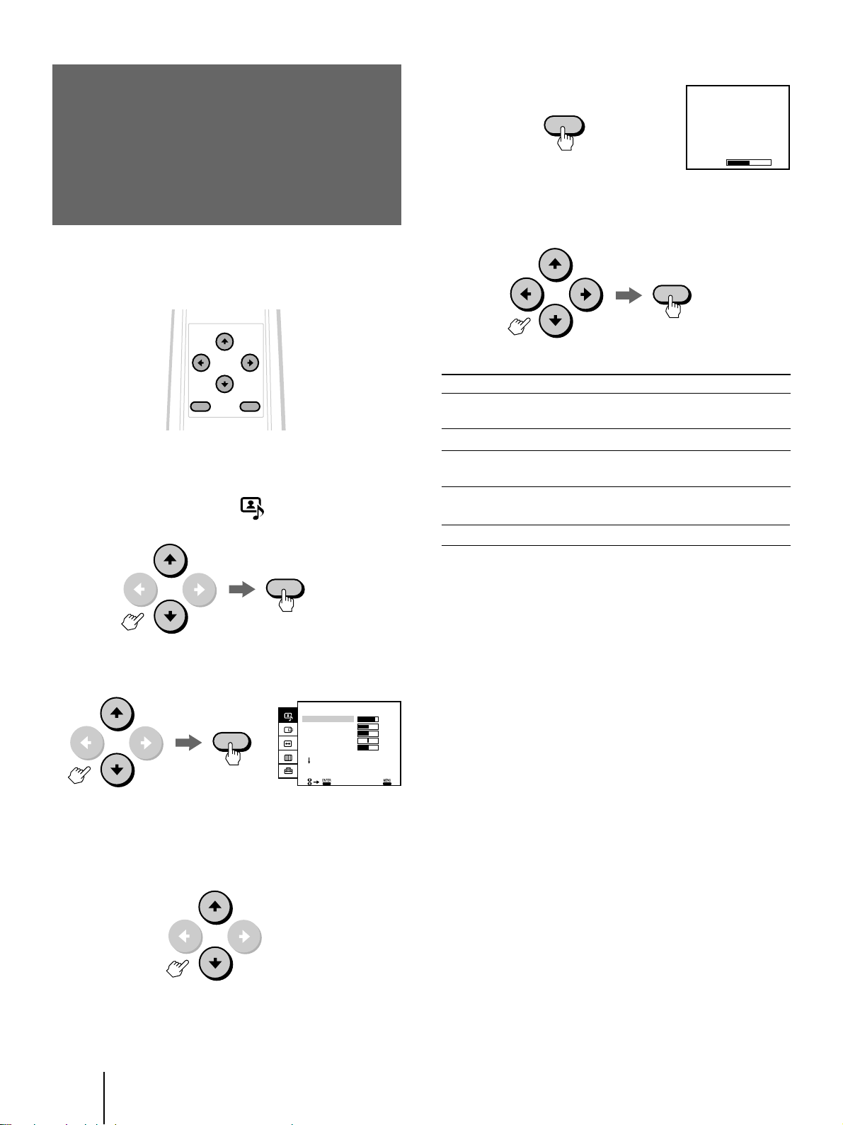
Adjusting the
BRIGHTNESS
50
picture
You can adjust the quality of the picture to suit your
taste and store the settings into AV MEMORY.
(AV MEMORY)
(2) Press ENTER.
ENTER
5 Adjust the selected item.
Press v, V, B or b to adjust the item, and press
ENTER.
ENTER
MENU ENTER
1 Press MENU.
2 Press v or V to select “ (VIDEO/AUDIO),”
and press ENTER.
ENTER
3 Press v or V to select VIDEO ADJUST, and
press ENTER.
VIDEO ADJUST
CONTRAST 80
ENTER
BRIGHTNESS
COLOR
HUE
SHARPNESS
RESET
EXI T
4 Select the item you want to adjust.
For example:
(1) To adjust the brightness, press v or V to select
BRIGHTNESS.
Item
CONTRAST
BRIGHTNESS
COLOR
HUE
SHARPNESS
Press v or B to
Decrease picture
contrast.
Darken the picture.
Decrease color
intensity.
Make picture tones
purplish.
Soften the picture.
Press V or b to
Increase picture
contrast.
Brighten the picture.
Increase color intensity.
Make picture tones
greenish.
Sharpen the picture.
6 To adjust other items, repeat steps 4 and 5.
7 Press MENU to return to the original screen.
To reset to the factory preset setting
Select RESET from the VIDEO ADJUST menu, and
press ENTER. See page 26 for additional reset
50
50
0
50
methods.
Notes
• When an RGB signal is input, COLOR and HUE cannot be
adjusted.
• You can adjust the items in AV MEMORY for each input from
VIDEO 1, 2 and 3 IN, RGB 1 IN, RGB 2 IN, and COMPONENT
IN.
• You can operate the menu using the √/◊/ı/∫ and the ENTER
buttons inside the drop-down panel on the front of the
monitor.
20
-GB
Operations
Page 21
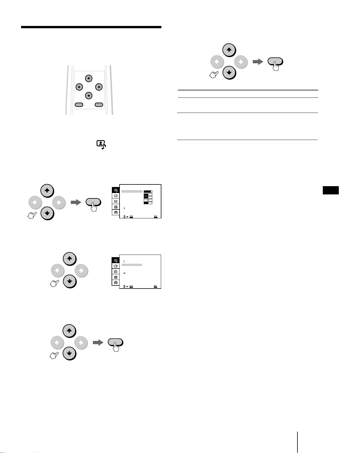
Adjusting the picture in more detail
You can adjust the picture with the H-WHITE and
COLOR TEMP (temperature) options.
6 Press v or V to adjust the item, then press
ENTER.
ENTER
MENU ENTER
1 Press MENU.
2 Press v or V to select “ (VIDEO/AUDIO),”
and press ENTER.
3 Press v or V to select VIDEO ADJUST, and
press ENTER.
VIDEO ADJUST
CONTRAST 80
ENTER
BRIGHTNESS
COLOR
HUE
SHARPNESS
RESET
EXI T
4 Press v or V to scroll down to RESET, then
press v again.
VIDEO ADJUST
H–WHITE:
COLOR TEMP:
RESET
OFF
MEDIUM
Choose
H-WHITE
To
Emphasize the white colors of a
picture by turning it ON.
COLOR TEMP (Color
temperature)
Make the white colors warm
(reddish) in the LOW position or
make the whites cool (bluish) in the
HIGH position.
7 To adjust other items, repeat steps 5 and 6.
8 Press MENU to return to the original screen.
To reset to the factory preset setting
50
50
0
50
Select RESET on the second page of the VIDEO
ADJUST menu, and press ENTER. See page 26 for
additional reset methods.
Notes
• You can adjust the items in AV MEMORY for each input from
VIDEO 1, 2 and 3 IN, RGB 1 IN, RGB 2 IN, and COMPONENT
IN.
• When an RGB signal is input, you cannot adjust H-WHITE.
• You can operate the menu using the √/◊/ı/∫ and the ENTER
buttons inside the drop-down panel on the front of the
monitor.
GB
5 Select the desired item with v or V, then
press ENTER.
ENTER
EXI T
Operations
21
-GB
Page 22
Adjusting the sound
(AV MEMORY)
4 Select the item you want to adjust.
For example:
(1) To adjust the bass, press v or V to select BASS.
You can adjust the quality of the sound to suit you taste
and store the settings into AV MEMORY.
MENU ENTER
1 Press MENU.
2 Press v or V to select “ (VIDEO/AUDIO),”
and press ENTER.
ENTER
3 Press v or V to select AUDIO ADJUST, and
press ENTER.
(2) Press ENTER.
ENTER
BASS
5 Adjust the selected item.
Press v, V, B or b to adjust the item, and press
ENTER.
ENTER
Item
TREBLE
BASS
BALANCE
Press v or B to
Decrease the treble
response.
Decrease the bass
response.
Emphasize the left
speaker’s volume.
Press V or b to
Increase the treble
response.
Increase the bass
response.
Emphasize the right
speaker’s volume.
0
22
-GB
Operations
ENTER
AUDIO ADJUST
TREBLE 0
BASS
BALANCE
EFFECT: OFF
RESET
EXI T
0
0
7 Press MENU to return to the original screen.
To reset to the factory preset setting
Select RESET from the AUDIO ADJUST menu, and
press ENTER. See page 26 for additional reset
methods.
Notes
• You can adjust the items in AV MEMORY for each input from
VIDEO 1, 2 and 3 IN, RGB 1 IN, RGB 2 IN, and COMPONENT
IN.
• You can operate the menu using the √/◊/ı/∫ and the ENTER
buttons inside the drop-down panel on the front of the
monitor.
6 To adjust other items, repeat steps 4 and 5.
Page 23
Selecting the audio
5 Press v or V to select the desired item, and
press ENTER.
effect
(EFFECT)
Audio effect mode allows you to enjoy dynamic threedimensional sound effects.
MENU ENTER
1 Press MENU.
2 Press v or V to select “ (VIDEO/AUDIO),“
and press ENTER.
ENTER
ENTER
Choose
HALL SURROUND 1
HALL SURROUND 2
OFF
To
Receive dynamic three-
dimensional sound.
Watch a movie.
Cancel audio effect.
6 Press MENU to return to the original screen.
To reset to the factory preset setting
Select RESET from the AUDIO ADJUST menu, and
press ENTER. See page 26 for additional reset
methods.
Notes
• You can adjust the items in AV MEMORY for each input from
VIDEO 1, 2 and 3 IN, RGB 1 IN, RGB 2 IN, and COMPONENT
IN.
• You can operate the menu using the √/◊/ı/∫ and the ENTER
buttons inside the drop-down panel on the front of the
monitor.
GB
3 Press v or V to select AUDIO ADJUST, and
press ENTER.
AUDIO ADJUST
TREBLE 0
ENTER
BASS
BALANCE
EFFECT: OFF
RESET
EXI T
4 Press v or V to select EFFECT, and press
ENTER.
ENTER
0
0
Operations
23
-GB
Page 24
Turning the power
off automatically
(AUTO SHUT OFF)
You can set the monitor to turn off after a spcified time
has passed. The timer will start when the sync signal
from the computer shuts off.
MENU ENTER
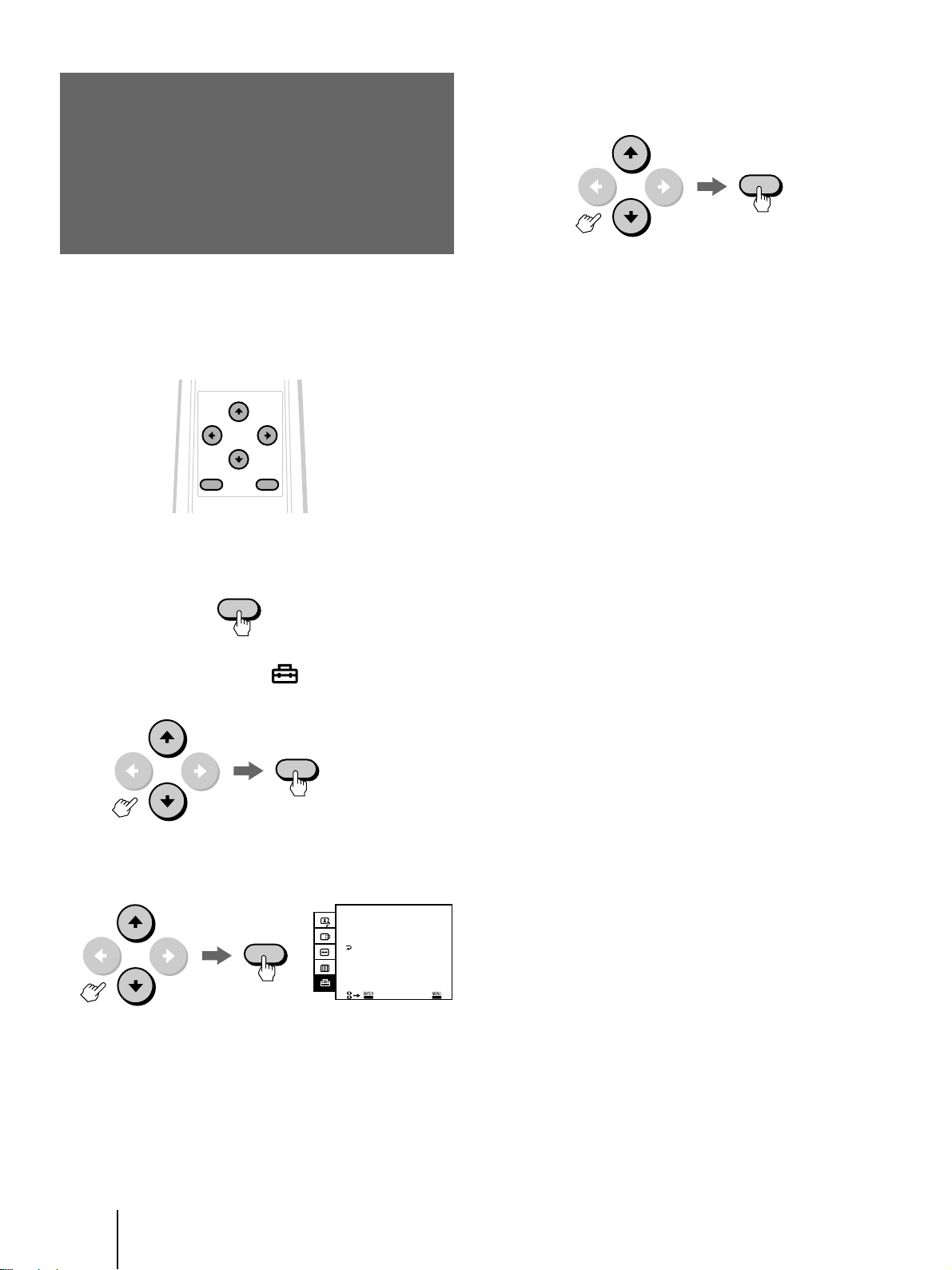
4 Press v or V to select 60 (minutes), 90
(minutes) or 120 (minutes), and press
ENTER.
ENTER
5 Press MENU to return to the original screen.
After the time you specify in step 4 has passed once
the sync signal is cancelled, the power turns off and
the STANDBY and u indicators will light up.
If you press 1/u on the remote control or a signal is
input from the computer again, the power will turn
on.
To cancel the AUTO SHUT OFF function
Select OFF in step 4 above.
Note
You cannot use this function for the input from VIDEO 1/2/3 IN
and COMPONENT IN.
1 Press MENU.
MENU
2 Press v or V to select “ (OPTION),” and
press ENTER.
ENTER
3 Press v or V to select AUTO SHUT OFF, and
press ENTER.
OPTION
AUTO SHUT OFF:
ENTER
LAMGUAGE:
COLOR SYSTEM:
ENGLISH
EXI T
OFF
AUTO
24
-GB
Operations
Page 25
Selecting the color
system
(COLOR SYSTEM)
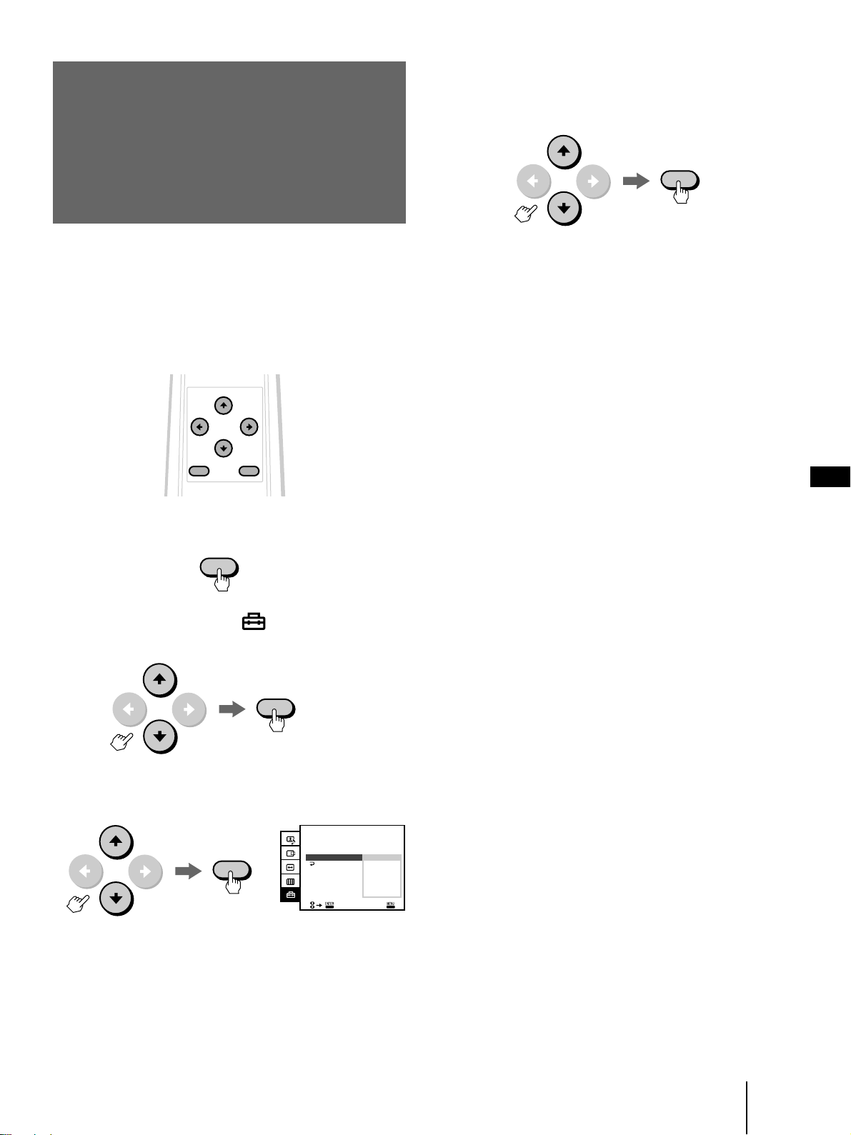
4 Press v or V to select an appropriate color
system, NTSC3.58, NTSC4.43, PAL, PAL M or
SECAM, and press ENTER.
ENTER
Normally, set COLOR SYSTEM to AUTO. The
appropriate color system will be automatically selected
for the input video signal. If the input signal is too
weak and the picture is distorted or colorless, select the
color system manually.
MENU ENTER
1 Press MENU.
MENU
2 Press v or V to select “ (OPTION),” and
press ENTER.
5 Press MENU to return to the original screen.
Notes
• You can operate the menu using the √/◊/ı/∫ and the ENTER
buttons inside the drop-down panel on the front of the
monitor.
• You cannot use this function for the input from RGB 1, 2 IN
and COMPONENT IN.
GB
ENTER
3 Press v or V to select COLOR SYSTEM, and
press ENTER.
OPTION
ENTER
AUTO SHUT OFF:
LANGUAGE:
COLOR SYSTEM:
ENGLISH
NTSC3.58
NTSC4.43
EXIT
OFF
AUTO
PAL
PAL M
SECAM
Operations
25
-GB
Page 26
Resetting the
Resetting all of the items in the menu
at the same time
adjusted items to
the factory preset
levels
Resetting an individual item in the
menu displayed on the screen
1 Press MENU.
MENU
2 Press v or V to select the menu which
contains the item to be reset, and press
ENTER.
VIDEO ADJUST
CONTRAST 80
ENTER
BRIGHTNESS
COLOR
HUE
SHARPNESS
RESET
EXI T
1 Press MENU.
2 Press v or V to select the menu you want to
reset, and press ENTER.
VIDEO ADJUST
ENTER
CONTRAST 80
BRIGHTNESS
COLOR
HUE
SHARPNESS
RESET
EXI T
50
50
0
50
3 Press RESET on the monitor.
All of the items in the menu displayed on the
screen will be restored to the factory preset levels.
RESET
50
50
0
50
Resetting the adjusted items for the
signal currently displayed on the
screen
3 Press v or V to select the item you want to
reset, and press ENTER.
ENTER
BRIGHTNESS
4 Press RESET on the monitor.
The selected item in the menu will be restored to
the factory preset level.
RESET
Press RESET on the monitor while there is no menu on
the screen.
All of the adjusted items for the current signal (other
than VIDEO ADJUST and OPTION) will be restored to
the factory preset levels.
RESET
50
Resetting all of the adjusted items
Press and hold RESET on the monitor for more than 2
seconds.
All of the adjusted items for the monitor will be
restored to the factory preset levels.
RESET
26
-GB
Operations
Page 27
Additional Information
Cleaning the air
filter
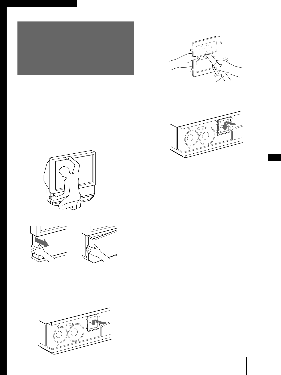
4 Remove the dust from the filter with a
vacuum cleaner.
After about 300-hours of use, the message, “CLEAN
THE FILTER,” will appear on the screen. In this case,
clean the air filter. When it becomes difficult to remove
the dust, replace the filter with a new one. To clean the
filter, follow the steps below.
1 Turn off the power switch on the monitor
and unplug the power cord.
2 Remove the front panel from the monitor.
Hold the monitor tightly.
Vacuum cleaner
5 Attach a new filter to the monitor.
Fit the four projections to the monitor securely.
GB
6 Mount the front panel.
Be careful not to damage the speakers.
Notes
• Clean the air filter when the message, “CLEAN THE FILTER,”
appears on the screen. If you do not, internal heat may build
up.
• Do not use a torn filter. Fit the four projections on the filter to
the monitor securely. Dust inside the monitor may cause
picture distortion and fire.
• Be sure to attach the air filter securely; otherwise, the monitor
will not turn on.
• Contact your Sony dealer for a new filter.
Grasping the left end of the front panel
with your fingers, pull the panel towards
you. Repeat this step with the right end of
the panel. Be careful not to catch your
fingernails.
3 Pull the air filter upwards to remove.
Additional Information
27
-GB
Page 28
Replacing a lamp
If the screen becomes dark, the color looks unusual, or
the LAMP indicator on the front of the monitor flashes,
it is time to replace the lamp with a new one.
Disposal of the Used Lamp
Sony regards protection of the environment as
extremely important.
Kindly put the used lamp in the new lamp’s package
and send it to the sales company whose address
appears on the new lamp’s guaranty card.
Before replacement
• Be sure to use a Sony XL-100 series lamp unit (not supplied)
for replacement. Use of other lamps may damage the monitor.
• Do not remove the lamp for any purpose other than
replacement.
• When replacing the lamp, let it cool down completely as the
surface of the lamp remains extremely hot for at least 30
minutes after the power has been turned off.
• Do not leave the removed lamp near flammable materials.
• Do not pour water onto the removed lamp, nor put any object
inside the lamp.
• Do not put inflammable materials and metal objects inside the
lamp receptacle on the monitor, after removing the lamp. Do
not touch the receptacle.
• Fit the new lamp securely, otherwise the screen may become
dark, or it may cause a fire.
1 Turn off the power switch on the monitor
and unplug the power cord.
Wait at least 30 minutes to allow the lamp to cool
down before replacing it .
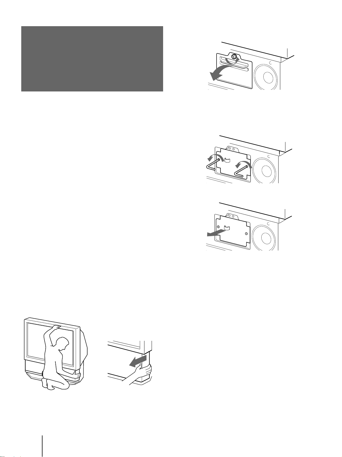
2 Remove the front panel.
3 Loosen the screw with a coin or similar
object to remove the lamp cover.
4 Loosen the two screws that secure the
lamp, then pull out the lamp.
The lamp is very hot immediately after use. Never
touch the front glass of the lamp or the
surrounding parts.
Loosen the two screws with the hexagon
head wrench (supplied with the lamp).
Hold the handle and pull out straight
towards you.
Place the removed lamp into the empty box of the
replacement lamp.
5 Mount the new lamp and tighten the two
screws securely using the hexagon head
wrench.
Hold the monitor tightly.
-GB
28
Additional Information
Grasping the right end of the
front panel with your fingers, pull
the panel towards you. Repeat
this step with the left end of the
panel. Be careful not to catch
your fingernails.
6 Mount the lamp cover and tighten the
screw.
7 Mount the front panel.
Be careful not to damage the monitor’s speakers.
Notes
• Do not touch the front glass of a new lamp or the glass of the
lamp receptacle. This may reduce picture quality or lamp life.
• Be sure to attach the lamp securely; otherwise, the monitor will
not turn on.
• A loud sound may be heard when the lamp burns out. This is
not dangerous.
• Consult your Sony dealer for obtaining the following lamp
units:
XL-100 (for Japan)
XL-100U (for the U.S.)
XL-100E (for Europe)
XL-100M (for all other areas)
Page 29

Troubleshooting
If the problem persists after trying the methods below,
contact your nearest Sony dealer.
No picture
/ Check that the power cord is connected
firmly.
/ Is the power of the monitor turned on?
/ Is the air filter mounted securely? (page 27)
/ Is the lamp cover attached securely? (page
28)
/ Check that the power of the connected
equipment is turned on.
/ Try to press any key on the connected
computer’s keyboard.
/ Check that the RGB signal cable or audio/
video cords are properly connected. (The
supplied HD15-HD15 adaptor may be
needed for some models of IBM PC/AT or
compatible computers. For a Macintosh or
compatible computer, use the supplied
Macintosh adaptor.) (pages 7 and 8)
/ Make sure that no pins on the HD15
connectors are bent.
/ Check that the connected computer’s video
card is seated completely in the proper bus
slot.
/ Check that the frequency range of the input
signal is within that specified for the
monitor. (If not, “OUT OF SCAN RANGE”
appears on the screen.) (page 9)
/ The monitor does not accept an interlace
mode signal that is not a preset mode
signal.
/ For customers using Windows 95/98 — If
“KL-X9200” is not displayed as “Monitor
type” in the device selection screen in
Windows 95/98, select “Plug and Play
monitor (VESA DDC)” as “Monitor type.”
Picture and sound output are delayed
/ When the green u (power) indicator on the
front is flashing, the monitor is warming
up.
/ To protect the lamp, the monitor does not
immediately output the picture and sound
if you try to turn on the power more than 5
seconds after the power has been turned
off.
Good picture, no sound
/ Press VOL+ (VOLUME+).
/ Press MUTING so that “MUTING”
disappears from the screen. (page 16)
/ The volume of the computer may be low.
/ Check that the audio connecting cord is
connected firmly to the audio outputs on
the computer.
Fuzzy picture
/ If you use the monitor in a cold place,
moisture condensation may have occurred.
Leave the monitor as it is to let the
moisture evaporate.
Dark picture
/ Replace the lamp for the light source with a
new one. (page 28)
No color, abnormal color
/ Adjust the picture in the VIDEO ADJUST
menu. (pages 20 and 21)
/ Select an appropriate color system from the
COLOR SYSTEM option in the OPTION
menu to obtain optimum color.
Computer picture not clear
/ Adjust PITCH, then PHASE in the DOT
ADJUST menu. (page 18)
Horizontal lines of the computer picture are
not visible.
/ Check that TIMING in the DOT ADJUST
menu is set to YES. (page 18)
Computer picture not centered or sized
properly
/ Adjust the centering and size so that the
picture fits the screen. (pages 16 and 17)
GB
(continued)
Additional Information
29
-GB
Page 30
Distorted picture
/ Check your video card manual for the
proper monitor setting.
/ Check that the frequency and the graphic
mode of the signal you are trying to input
is within the acceptable range. (page 9)
Even if the signal is within the proper
range, some video cards may have a sync
pulse that is too narrow for the monitor to
sync correctly.
What the indicators on the front of the
monitor mean
No picture, no sound from the connected
equipment
/ Are all of the cords connected correctly?
/ Press the RGB, VIDEO or COMPONENT
button on the remote control. (page 15)
The remote control does not function.
/ Are the batteries worn out?
/ If additional equipment is connected to the
CONTROL S IN jack on the rear of the
monitor, the remote control detector does
not function. Disconnect any equipment
connected to the CONTROL S IN jack.
(page 13)
The humming noise of the fans is heard even
after the monitor has been turned off.
/ The fans installed inside the monitor are
working to prevent internal heat build-up.
They will stop in about 2 minutes.
LAMP
STANDBY
The u (power) (green), STANDBY (orange) and/or
LAMP (orange) indicators indicate the condition of the
monitor and provide warnings by lighting or flashing,
as shown below.
The u indicator lights up.
/ The power of the monitor is on.
The STANDBY indicator lights up.
/ The monitor is in standby mode. The
monitor is turned on by pressing 1/u on
the remote control.
The u and STANDBY indicators light up.
/ The AUTO SHUT OFF function is working.
The monitor has been turned off when the
time you specify has passed after the input
from the computer is cut off.
30
-GB
Additional Information
The u indicator flashes.
/ The lamp is preparing to turn on. Picture
and sound will appear momentarily.
The LAMP and STANDBY indicators flash.
/ The air filter or the lamp cover is not
attached securely. When you secure the
cover, the STANDBY indicator lights up
and the LAMP indicator turns off. (pages
27 and 28)
The LAMP indicator flashes.
/ The lamp for the light source has burnt out.
Replace it with a new one. (page 28)
The LAMP, STANDBY and u indicators flash.
The LAMP and u indicators flash.
The STANDBY and u indicators flash.
/ Contact qualified Sony personnel and
inform them of the monitor’s condition.
Page 31

Specifications
Acceptable signal (Appendix)
NTSC3.58/NTSC4.43/PAL/PAL M
/SECAM video signal, switched
automatically
RGB signal
Projection system 3 LCD panels, 1 lens projection
LCD panel 1.3-inch TFT LCD panel
Lamp XL-100M: HID lamp, 100 W
Lens Large diameter hybrid lens F2.4
Screen size (measured diagonally)
Viewable image size
Frequency range Horizontal: 24.8 to 85 kHz
Inputs/outputs
VIDEO 1, 2 and 3 IN S VIDEO (4-pin mini-DIN):
COMPONENT IN VIDEO (phono jacks):
VIDEO OUT S VIDEO (4-pin mini-DIN):
(For details, see page 9.)
system
Approx. 2.36 million dots
(786,432 pixels)
1,024 × 768 dots × 3 panels
50 inches
Approx. 50 inches (diagonally)
Approx. 1,016 × 762 mm (w/h)
Vertical: 50 to 85 Hz
Y: 1 Vp-p, 75 ohms
unbalanced, sync negative
C: 0.286 Vp-p (NTSC burst
signal), 75 ohms
0.3 Vp-p (PAL burst signal), 75
ohms
VIDEO (phono jacks):
1 Vp-p, 75 ohms unbalanced,
sync negative
AUDIO (phono jacks):
2 channels, 500 mVrms
Impedance: more than 47
kohms
Y: 1 Vp-p, 75 ohms, sync
negative
B/CB/B-Y: 0.7 Vp-p, 75 ohms
P
R/CR/R-Y: 0.7 Vp-p, 75 ohms
P
AUDIO (phono jacks): 500
mVrms (100% modulation)
Impedance: 47 kilohms
Y: 1 Vp-p, 75 ohms
unbalanced, sync negative
C: 0.286 Vp-p (NTSC burst
signal), 75 ohms
0.3 Vp-p (PAL burst signal), 75
ohms
VIDEO (phono jack):
1 Vp-p, 75 ohms unbalanced,
sync negative
AUDIO (phono jacks):
2 channels, 500 mVrms
Impedance: less than 1 kohms
RGB 1, 2 IN
RGB OUT
D-sub 15-pin, female
VIDEO: R, G, B: 0.7 Vp-p,
positive, 75 ohms
SYNC: Sync on Green: 0.3 Vp-p
HD: Composite sync:
TTL, high impedance,
sync positive/negative
Horizontal sync: TTL, high
impedance, sync positive/
negative
VD: Vertical sync: TTL, high
impedance, sync positive/
negative
AUDIO (RGB 1 IN) (phono
jacks)
2 channels, 500 mVrms
Impedance: more than 47 kohms
AUDIO (RGB 2 IN) (stereo
minijack)
500 mVrms
Impedance: more than 47 kohms
D-sub 15-pin, female
VIDEO: R, G, B: 0.7 Vp-p,
positive, 75 ohms
SYNC: Sync on Green: 0.3 Vp-p
HD: Composite sync:
TTL, high impedance,
sync positive/negative
Horizontal sync: TTL, high
impedance, sync positive/
negative
VD: Vertical sync: TTL, high
impedance, sync positive/
negative
AUDIO (phono jacks)
2 channels, 500 mVrms
Impedance: less than 1 kohm
Speaker output Front: 5 W × 2 (L/R)
Power requirement
Power consumption
Dimensions 1,125 × 1,087 × 610 mm (44
Woofer: 15 W
100 to 240 V AC, 50/60 Hz
220 W (MAX)
Standby mode: 4 W
7
/8 × 24 1/8 inches) (w/h/d)
3
/8 × 42
Mass Approx. 43 kg (106 lbs 8 oz)
Supplied accessories
Optional accessories
Design and specifications are subject to change without
notice.
Remote control RM-902 (1)
Size AA (R6) batteries (2)
AC power cord (1)
RGB signal cable (D-sub 15-pin
˜ D-sub 15-pin) (1)
HD15-HD15 (male, without the
No. 9 pin) adaptor (1)
Macintosh adaptor (1)
Windows Monitor Information
Disk/Utility Disk (1)
Macintosh Utility Disk (1)
Brackets (2)
Screws for brackets (2)
Hexagon head wrench (1)
Lamp unit: XL-100 (for Japan)
XL-100U (for the U.S.)
XL-100E (for Europe)
XL-100M (for all other areas)
Monitor stand: SU-90T (only for
Japan), SU-90U (only for the
U.S.)
GB
Additional Information
31
-GB
Page 32

Identifying the
parts
This section briefly describes the buttons and controls
on the monitor and on the remote control. For more
information, refer to the pages next to each description.
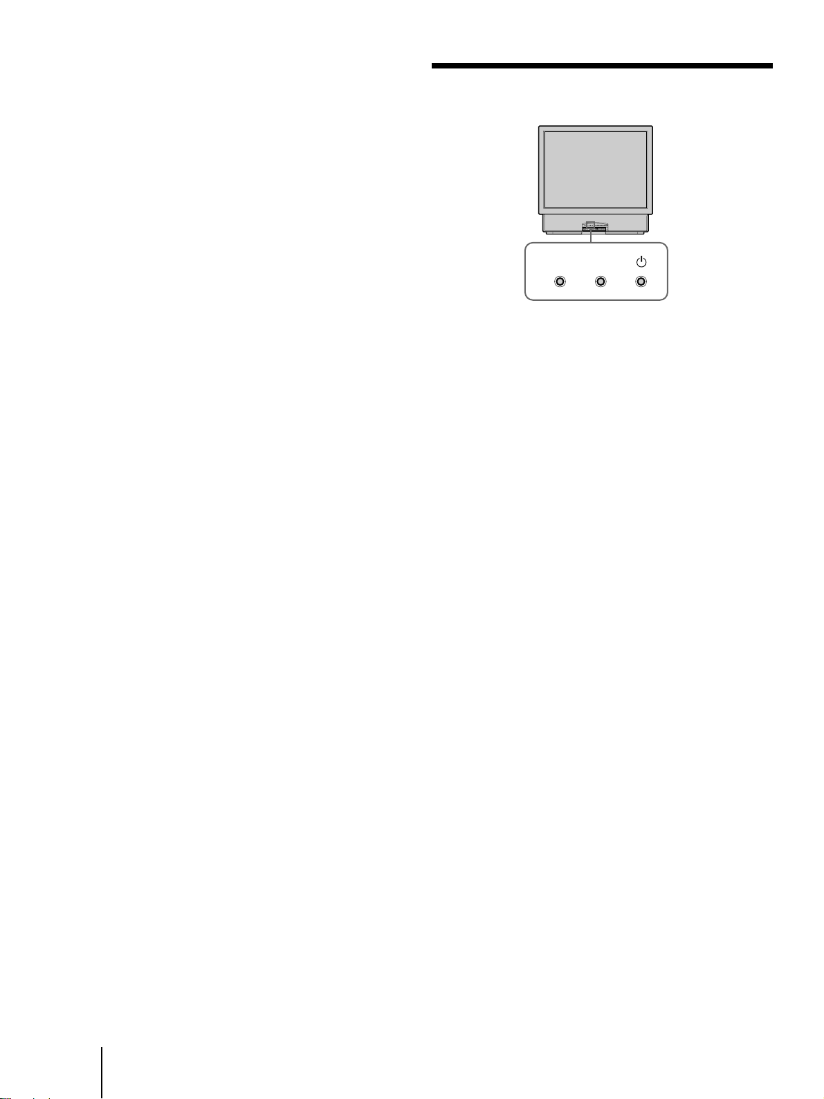
Projection monitor — Front
With the front panel attached
Front panel
LAMP RGB
STANDBY
RGB 2 IN
VIDEO 2 IN
With the front panel removed
Air filter part
(page 27)
COMPONENT
RESET MENU ENTER
VIDEO –VOLUME+
Lamp part
(page 28)
RGB
AUDIO
S VIDEO VIDEO
1 Remote control sensor
2 LAMP indicator (pages 28, 30)
3 STANDBY indicator (pages 15, 24, 30)
4 u (power) indicator (pages 15, 24, 30)
5 RGB button (page 15)
6 COMPONENT button (page 15)
7 VIDEO button (page 15)
8 VOLUME +/– buttons (page 15)
-GB
32
Additional Information
LR
AUDIO
9 RGB 2 IN connector/AUDIO IN jack (pages 7,
8)
!º VIDEO 2 IN jacks (page 11)
!¡ RESET button (pages 17, 26)
!™ MENU button (page 14)
!£ √/◊/ı/∫ buttons (page 14)
!¢ ENTER button (page 14)
!∞ u (power) switch (page 15)
Page 33

Projection monitor — Rear
VIDEO IN VIDEO
13
S VIDEO
VIDEO
L
AUDIO
R
OUT
COMPONENT IN
Y
PB/CB/B-Y
PR/CR/R-Y
L
AUDIO
R
12345 6 7 8
1 AC IN socket (page 13)
2 VIDEO 1 IN jacks (pages 11, 12)
3 VIDEO 3 IN jacks (pages 11, 12)
4 VIDEO OUT jacks (page 11)
5 COMPONENT IN jacks (page 12)
6 RGB 1 IN connector/AUDIO IN jack (pages 7,
8, 10)
7 CONTROL S IN/OUT jacks (page 13)
8 RGB OUT connector/AUDIO OUT jack (page
10)
RGB 1 IN
AUDIO
RL
RGB OUT
AUDIO
RL
CONTROL S
IN OUT
RGB
RGB
GB
(continued)
Additional Information
33
-GB
Page 34

Remote control
MUTING
VIDEO
MENU ENTER
VOL
DISPLAY
COMPONENT
RGB
1 DISPLAY button (page 16)
2 MUTING button (page 16)
3 VIDEO button (page 15)
4 MENU button (page 14)
5 VOL (volume) +/– buttons (page 15)
6 1/u (power) button (page 15)
7 RGB button (page 15)
8 COMPONENT button (page 15)
9 v/V/B/b buttons (page 14)
!º ENTER button (page 14)
34
-GB
Additional Information
Page 35

Index
Adjusting
the audio effect 23
the color temperature 21
the color system 25
the picture 20
the picture in more detail 21
the picture position 16
the picture size 17
the sound 22
Air filter 27
AUDIO ADJUST 22
Audio effect 23
AUTO SHUT OFF 24
AV MEMORY 20, 22
CENTER 16
Changing the menu language 14
COLOR SYSTEM 25
CONTROL S jacks 13
DOT ADJUST 18
DVD player 12, 15
Graphic mode 9
Hookups
to a computer 7, 8
to another monitor 10
to a DVD player 12
to the AC outlet 13
to video equipment 11
Horizontal frequency 9
IBM PC/AT computer 3, 7
Identifying the parts 32
Installing the monitor 5
Lamp
flashing 30
replacement 28
LAMP indicator 28, 30
Macintosh or compatible computer 3, 8
Muting 16
OPTION 14, 24, 25
OUT OF SCAN RANGE 9, 16
PITCH adjustment 18
PHASE adjustment 18
Preset mode 9
Remote control
identifying the parts 34
inserting batteries 14
Plug & Play 9
u (power) indicator 15, 24, 30
Reset 26
Selecting the preset picture viewing mode 19
SIZE 17
Stabilizing the monitor 6
STANDBY indicator 15, 24, 30
Surround 23
S VGA 9
TIMING adjustment 18
User mode 9
Utility Disk 18
Vertical frequency 9
VESA 3, 9
VGA 3, 9
VIDEO ADJUST 20, 21
VIDEO/AUDIO 19–23
Viewing area 5
Watching
the picture 15
Wide Resolution 17
XGA 9
GB
Additional Information
35
-GB
Page 36

AVERTISSEMENT
Afin d’éviter tout risque d’incendie ou
d’électrocution, ne pas exposer cet
appareil à la pluie ou à l’humidité.
CAUTION
RISK OF ELECTRIC SHOCK
DO NOT OPEN
ATTENTION
RISQUE DE CHOC ELECTRIQUE,
NE PAS OUVRIR
PRECAUCION
RIESGO DE CHOQUE ELECTRICO
NO ADRIR
NO ABRIR
ATTENTION
Pour prévenir les chocs électriques, ne pas utiliser cette
fiche polarisée avec un prolongateur, une prise de
courant ou une autre sortie de courant, sauf si les lames
peuvent être insérées à fond sans en laisser aucune
partie à decouvert.
ATTENTION : PUOR REDUIRE LE RISQUE DE DECHARGE ELECTRIQUE.
NE PAS OUVRIR LE COUVERCLE (OU LE PANNEAU ARRIERE).
COMPORTE DES PIECES NE POUVANT ETRE
ENTRETENUES PAR L,UTILISATEUR.
CONFIER L,ENTRETIEN A DES TECHNICIENS QUALIFIES.
Ce sigle vise à signaler à l’utilisateur la
présence d’une “tension dangereuse” non
isolée au sein de l’appareil, dont la puissance
peut être suffisante pour provoquer un risque
d’électrocution.
Ce sigle vise à signaler à l’utilisateur la
présence d’une documentation importante
concernant les instructions de fonctionnement
et d’entretien de cet appareil.
-FR
2
Page 37

Table des matières
4 Précautions
Installation
5 Etape 1: Installation du moniteur de projection
7 Etape 2: Raccordement
14 Etape 3: Réglage de la télécommande
14 Modification de la langue de menu
Utilisation
15 Projection de l’image
16 Réglage de l’image d’un ordinateur
19 Sélection du mode de visionnage d’image
présélectionné
20 Réglage de l’image (MEMOIRE AV)
22 Réglage du son (MEMOIRE AV)
23 Sélection de l’effet audio (EFFET)
24 Mise hors tension automatique (COUPURE AUTO)
25 Sélection du système couleur (STANDARD)
26 Réinitialisation des paramètres réglés aux valeurs
par défaut
FR
•DDC est une marque de commerce de Video
Electronics Standard Association.
•IBM PC/AT et VGA sont des marques de
commerce de International Business Machines
Corporation déposées aux Etats-Unis.
•Macintosh est une marque de commerce brevetée
d’Apple Computer Inc., déposée aux Etats-Unis et
dans d’autres pays.
•VESA est une marque déposée de Video
Electronics Standard Association.
•Windows est une marque de commerce de
Microsoft Corporation déposée aux Etats-Unis et
dans d’autres pays.
•Tous les autres noms de produits mentionnés dans
ce document peuvent être des marques de
commerce ou des marques de commerce déposées
de leurs sociétés respectives.
•Par ailleurs, “” et “” ne sont pas repris à chaque
fois dans ce manuel.
Informations complémentaires
27 Nettoyage du filtre à air
28 Remplacement de la lampe
29 Guide de dépannage
31 Spécifications
32 Identification des composants
35 Index
A-1Dimensions
Les termes entre parenthèses correspondent à des noms de
menus.
-FR
3
Page 38

Welcome!
Précautions
A propos de la suppression
Le moniteur affiche des bandes noires entre l’image et
les bords de l’écran parce que le moniteur procède à un
sous-balayage pour obtenir l’espace nécessaire sur
l’écran à l’affichage de l’image. Ce phénomène
s’appelle suppression. Sachez que les bandes noires sur
chaque bord de l’écran ne sont pas uniformes.
Pour le réglage de la taille et de la position de l’image,
reportez-vous aux pages 16 et 17.
Ce moniteur de projection fonctionne sur une très
haute tension. Veuillez vous conformer aux
précautions ci-dessous afin d’éviter tout risque
d’incendie ou d’électrocution.
Sécurité
• Vérifiez si la tension de service de votre appareil est
identique à la tension d’alimentation secteur locale.
• L’une des lames de la fiche est plus large que les
autres pour des raisons de sécurité et ne s’adapte
dans la prise que dans un seul sens. Si vous ne
parvenez pas à introduire complètement la fiche
dans la prise, prenez contact avec votre distributeur.
• Si un objet liquide ou solide pénètre à l’intérieur du
châssis, débranchez le téléviseur de projection et
faites-le contrôler par un personnel qualifié avant de
le remettre en service.
• Débranchez le cordon de la prise si vous prévoyez
de ne pas utiliser le téléviseur de projection pendant
une période de temps prolongée. Pour débrancher
le cordon, tirez-le par la fiche, jamais par le cordon.
• Les ventilateurs à l’intérieur du moniteur
continuent à tourner pendant un certain temps,
même après que le moniteur est mis hors tension.
Ne débranchez pas le moniteur de la prise secteur
lorsque les ventilateurs tournent.
Installation
• Veillez à assurer une circulation d’air adéquate afin
d’éviter la surchauffe de l’appareil.
• N’installez pas le téléviseur de projection dans un
endroit chaud ou humide ou exposé à une poussière
excessive ou à des vibrations mécaniques.
A propos de l’écran
La surface de l’écran se raye facilement. Ne pas frotter,
heurter ou tapoter l’écran avec des objets pointus ou
abrasifs.
Faites particulièrement attention lors du transport du
moniteur.
Suppression
Image
Bord de l’écran
A propos de la condensation d’humidité
Si le moniteur de projection est transporté directement
d’une pièce froide à une pièce chaude, ou si la
température ambiante varie brusquement, l’image
pourra être floue ou présenter une altération des
couleurs. La raison en est que l’humidité se condense
sur le miroir ou sur les objectifs intérieurs. Si cela se
produit, laissez-le sous tension et attendez que
l’humidité se soit évaporée avant d’utiliser le moniteur.
A propos du nettoyage
• Nettoyez le châssis du moniteur au moyen d’un
chiffon sec et doux. Les taches tenaces peuvent être
éliminées au moyen d’un chiffon légèrement
humidifié avec une solution d’eau et de savon non
corrosif, puis passez avec un chiffon sec et doux.
• N’utilisez aucun type de solvants tels que l’alcool, le
benzène, les diluants et les insecticides. Ces solvants
peuvent endommager la finition du moniteur ou
effacer les indications du panneau.
• Pour éliminer les poussières de l’écran, époussetezle légèrement à l’aide d’un chiffon doux en
imprimant.
• Les taches tenaces de l’écran peuvent être éliminées
au moyen d’un chiffon doux légèrement humidifié
avec une solution d’eau et de savon non corrosif.
• Si l’image s’assombrit après avoir utilisé le moniteur
pendant une période prolongée, il sera peut-être
nécessaire de nettoyer l’intérieur du moniteur.
Adressez-vous à un personnel d’entretien qualifié.
-FR
4
Page 39

Installation
Etape 1: Installation
du moniteur de
projection
Zone de visionnage optimale
Pour une image de meilleure qualité, installez l’écran
comme illustré ci-dessous.
Zone de visionnage verticale (vue de côté)
30°
30°
Transport de votre moniteur
Pour transporter le moniteur, ne le saisissez que par les
parties indiquées par les flèches. Deux personnes au
moins sont nécessaires pour le transport du moniteur.
FR
plus de 3,5 m
Zone de visionnage horizontale (vue du
dessus)
65°
65°
plus de 3,5 m
Installation
-FR
5
Page 40

Stabilisation du moniteur
Pour les clients au Japon et aux EtatsUnis uniquement
Utilisation des supports
Après l’installation, fixez le moniteur contre un mur,
etc. au moyen des supports fournis.
1 Placez les deux supports fournis au moyen
des vis dans les coins supérieurs à l’arrière
du moniteur.
Support (fourni)
2 Passez une grosse corde ou une chaîne à
travers chaque support monté à l’étape 1,
puis fixez-la à un mur ou à une colonne, etc.
Utilisation des sangles de fixation (non
fournies)
Vous pouvez également utiliser la sangle de fixation
BLT-R10 pour le support du moniteur (non fourni) de
manière à maintenir celui-ci.
Nous conseillons l’utilisation du support de moniteur
SU-90 avec lequel les sangles de fixation sont fournies.
A propos du support de moniteur SU-90 (non
fourni)
Les dimensions du support sont de 1.050 × 700 × 630
mm (41 3/8 × 27 5/8 × 24 7/8 pouces) (largeur/hauteur/
profondeur). Avant d’acheter ce support, prenez note
des mesures ci-dessus et vérifiez les dimensions de
l’endroit où vous comptez installer le support.
Les clients au Japon doivent utiliser le support SU90T. Les clients aux Etats-Unis doivent utiliser le
support SU-90U.
Arrière
Avant
-FR
6
Installation
Page 41

Etape 2:
Raccordement
Avant d’effectuer les raccordements, mettez l’appareil
hors tension et débranchez les cordons d’alimentation
du moniteur et de l’équipement à raccorder. Se reporter
au mode d’emploi de l’équipement que vous raccordez.
Raccordement à un ordinateur IBM PC/
AT ou compatible
Branchez le connecteur RGB 2 IN situé à l’avant ou le
connecteur RGB 1 IN situé à l’arrière du moniteur à la
sortie vidéo de l’ordinateur au moyen du câble de
signal RVB fourni (D-sub à 15 broches ˜ D-sub à 15
broches). Utilisez un câble de connexion audio (non
fourni) pour établir les raccordements audio.
Utilisation du connecteur RGB 2 IN
avant
Avant du moniteur
RGB 2 IN
RGB
AUDIO
S VIDEO
Utilisation du connecteur RGB 1 IN
arrière
Arrière du moniteur
RGB 1 IN
RL
RL
Cordon de
raccordement audio
(fiche phono × 2 ˜
minifiche stéréo)
(non fourni)
vers la sortie audio
AUDIO
RGB OUT
AUDIO
RGB
RGB
ou
Adaptateur
HD15–HD15
(fourni)*
vers la sortie vidéo
Câble de signal
RVB (fourni)
Côté mâle
(sans la broche
n°9)
FR
Câble de signal
RVB (fourni)
Adaptateur
HD15–HD15 (fourni)*
Côté mâle
(sans la broche n°9)
vers la sortie vidéo
ou
Cordon de
raccordement audio
(minifiche stéréo ˜
minifiche stéréo)
(non fourni)
vers la sortie audio
Ordinateur IBM PC/AT ou
compatible
Ordinateur IBM PC/AT ou
compatible
* L’adaptateur HD15–HD15 (fourni) sera peut-être nécessaire sur
certains modèles. Le côté mâle (sans la broche n°9) de
l’adaptateur devra être raccordé à l’ordinateur.
Pour les utilisateurs de l’adaptateur HD15–
HD15 fourni
Ce moniteur utilise une broche n°9 dans le connecteur
du signal vidéo pour la compatibilité DDC1 et DDC2B.
Certains ordinateurs non compatibles avec DDC1 ou
DDC2B peuvent ne pas accepter la broche n°9. Si vous
ne savez pas si votre ordinateur accepte la broche n°9
ou non, utilisez l’adaptateur HD15 (femelle) – HD15
(mâle sans broche n°9) (fourni).
Installation
-FR
7
Page 42

Raccordement à un Macintosh ou
RGB
RGB OUT
RGB 1 IN
RL
AUDIO
RL
AUDIO
RGB
ordinateur compatible
Utilisation du connecteur RGB 1 IN
arrière
Branchez le connecteur RGB 2 IN situé à l’avant ou le
connecteur RGB 1 IN situé à l’arrière du moniteur à la
sortie vidéo de l’ordinateur au moyen du câble de
signal RVB fourni (D-sub à 15 broches ˜ D-sub à 15
broches) et de l’adaptateur Macintosh fourni. Utilisez
un câble de connexion audio (non fourni) pour établir
les raccordements audio.
Utilisation du connecteur RGB 2 IN
avant
Avant du moniteur
RGB 2 IN
RGB AUDIO
Câble de signal RVB
(fourni)
S VIDEO
Cordon de
raccordement audio
(minifiche stéréo ˜
minifiche stéréo)
(non fourni)
Arrière du moniteur
Cordon de raccordement
audio
(fiche phono × 2 ˜
minifiche stéréo)
(non fourni)
vers la sortie vidéovers la sortie audio
Câble de signal
RVB (fourni)
Adaptateur
Macintosh
(fourni)
Adaptateur Macintosh
(fourni)
-FR
8
vers la sortie vidéo vers la sortie audio
Installation
Macintosh ou ordinateur
compatible
Macintosh ou ordinateur
compatible
A propos de l’adaptateur Macintosh fourni
L’adaptateur Macintosh fourni est compatible avec les
ordinateurs des séries Macintosh LC, Performa, Quadra
and Power Macintosh. La série Macintosh II et
certaines versions des modèles PowerBook peuvent
nécessiter un autre adaptateur avec
microcommutateurs (non fourni).
Page 43

Mode de présélection et mode
utilisateur
Le moniteur détecte automatiquement les signaux
d’entrée d’une fréquence de balayage horizontal
comprise entre 24,8 et 85,0 kHz et d’une fréquence de
balayage vertical comprise entre 50 et 85 Hz. Nous
conseillons cependant d’utiliser un signal d’une
fréquence de balayage verticale de 60 Hz puisque
l’affichage à l’écran risque de se désactiver pendant
quelques secondes chaque fois qu’un signal d’une
fréquence différente de 60 Hz est entré sur le moniteur.
Le moniteur est capable d’une résolution d’affichage de
1.024 × 768 points. Si un signal d’une résolution
supérieure est entré, il est traité de manière à afficher
l’image suivant une résolution de 1.024 × 768 points.
Modes de présélection
Le moniteur comprend des modes de présélection par
défaut correspondant aux normes industrielles les plus
courantes décrites ci-dessous.
N°
Résolution
(points × lignes)
1 640 × 350* 31,469 70,086 VGA mode 1 H-pos V-neg
2 640 × 400* 24,823 56,416 PC-9801 Normal H-neg V-neg
3 640 × 480 31,469 59,940 VGA mode 3 H-neg V-neg
4 640 × 480 35,000 66,667 Macintosh 13" H-neg V-neg
5 640 × 480 37,861 72,809 VGA VESA 72 Hz H-neg V-neg
6 640 × 480 37,500 75,000 VGA VESA 75 Hz H-neg V-neg
7 640 × 480 43,269 85,008 VGA VESA 85 Hz H-neg V-neg
8 720 × 400 31,469 70,087 VGA mode 2 H-neg V-pos
9 720 × 400 37,927 85,039 VGA VESA 85 Hz H-neg V-pos
10 800 × 600 35,156 56,250 SVGA VESA 56 Hz H-pos V-pos
11 800 × 600 37,879 60,317 SVGA VESA 60 Hz H-pos V-pos
12 800 × 600 48,077 72,188 SVGA VESA 72 Hz H-pos V-pos
13 800 × 600 46,875 75,000 SVGA VESA 75 Hz H-pos V-pos
14 800 × 600 53,674 85,061 SVGA VESA 85 Hz H-pos V-pos
15 832 × 624 49,727 74,553 Macintosh 16" H-neg V-neg
16 1024 × 768 35,522 43,479 XGA VESA 43 Hz H-pos V-pos
17 1024 × 768 48,363 60,004 XGA VESA 60 Hz H-neg V-neg
18 1024 × 768 56,476 70,069 XGA VESA 70 Hz H-neg V-neg
19 1024 × 768 60,023 75,029 XGA VESA 75 Hz H-pos V-pos
20 1024 × 768 60,241 74,927 Macintosh 19" H-neg V-neg
21 1024 × 768 68,677 84,997 XGA VESA 85 Hz H-pos V-pos
22 1152 × 864 67,500 75,000 SXGA VESA 75 Hz H-pos V-pos
23 1152 × 870 68,681 75,060 Macintosh 21" H-neg V-neg
24 1280 × 960 60,000 60,000 SXGA VESA 60 Hz H-pos V-pos
25 1280 × 1024 46,433 43,436 SXGA VESA 43 Hz H-pos V-pos
26 1280 × 1024 63,981 60,020 SXGA VESA 60 Hz H-pos V-pos
27 1280 × 1024 79,976 75,025 SXGA VESA 75 Hz H-pos V-pos
* Le moniteur projette l’image de format 4:3.
Fréquence Fréquence
horizontale verticale
(kHz) (Hz)
Mode graphique Sync
Modes utilisateur
Si vous utilisez un mode vidéo qui n’est pas l’un des
modes par défaut, il est possible que vous deviez
syntoniser finement le moniteur de façon à obtenir la
qualité d’affichage voulue. Il vous suffit pour cela de
régler le moniteur suivant les instructions de réglage
aux pages 16 à 18. Les réglages sont mémorisés
automatiquement et rappelés chaque fois que le mode
afférent est activé.
Conditions de synchronisation
horizontale préconisées
Largeur de synchronisation horizontale de plus de 1,0
µs.
Largeur de neutralisation horizontale de plus de 3,6 µs.
Si un signal d’une plage de fréquence
incompatible avec celle du moniteur
est entré
“HORS PLAGE DE BALAYAGE” apparaît à l’écran.
Le moniteur n’accepte pas un signal en mode
d’entrelacement qui n’est pas un signal de mode de
présélection. Par ailleurs, si vous introduisez un signal
autre qu’un signal de mode présélectionné avec une
horloge de point de plus de 140 MHz, il se peut que
l’image soit distordue.
Fonction Plug & Play
Ce moniteur satisfait aux normes DDCTM1 et DDC2B
qui sont les normes Display Data Channel (DDC) de
VESA.
Si un serveur DDC1 est connecté, le moniteur se
synchronise avec V. CLK suivant les normes VESA et
envoie les données EDID (Extended Display
Identification Data) par la ligne de données.
Si un serveur DDC2B est raccordé, le moniteur
commute automatiquement à chaque communication.
FR
Installation
(suite)
-FR
9
Page 44

Pour les clients utilisant Windows 95/
98
Pour maximaliser le potentiel de votre moniteur,
installez sur votre ordinateur le nouveau fichier
d’informations modèle depuis la disquette “Windows
Monitor Information Disk”.
Ce moniteur est conforme à la norme Plug & Play
“VESA DDC”. Si votre PC/carte graphique est
conforme à la norme DDC, sélectionnez “Plug & Play
Monitor (VESA DDC)” ou la désignation de ce
moniteur comme type de moniteur dans le “Control
Panel” sous Windows 95/98. Si votre PC/carte
graphique a des difficultés à communiquer avec ce
moniteur, chargez la disquette “Windows Monitor
Information Disk” et sélectionnez la désignation de ce
moniteur comme type de moniteur.
Raccordement d’un autre moniteur
Ce moniteur transmet le signal qui est entré par le
connecteur RGB 1 IN ou RGB 2 IN via le connecteur
RGB OUT, et peut afficher l’image sur un autre
moniteur.
Reportez-vous aux pages 7 et 8 pour le raccordement
de l’ordinateur.
Ordinateur
Arrière du moniteur
Voir pages 7 et 8 pour
vers RGB IN
le raccordement de
l’ordinateur.
Pour les clients utilisant Windows
NT4.0
L’installation du moniteur sous Windows NT4.0 est
différente de Windows 95/98 et n’implique pas la
sélection du type de moniteur. Reportez-vous au mode
d’emploi Windows NT4.0 pour plus de détails sur le
réglage de la résolution, le taux de régénération et le
nombre de couleurs.
Réglage de la résolution du moniteur
et du nombre de couleurs
Ajustez la résolution du moniteur et le nombre de
couleurs en vous référant au mode d’emploi de votre
ordinateur. Le nombre de couleurs peut varier selon
votre ordinateur ou votre carte vidéo. Le réglage de la
palette de couleurs et le nombre réel de couleurs se
présentent comme suit:
• High Color (16 bit) n 65.536 couleurs
• True Color (24 bit) n environ 16,77 millions de
couleurs
En mode True Color (24 bit), la vitesse peut étre
inférieure.
RL
RL
vers AUDIO R/L
vers l’entrée audio
RGB 1 IN
AUDIO
RGB OUT
AUDIO
vers l’entrée RGB
Un autre moniteur
RGB
RGB
vers RGB OUT
Le raccordement
varie suivant le type
de connecteur
d’entrée RGB de
l’autre moniteur.
Pour plus de détails,
reportez-vous au
mode d’emploi
fourni avec le
moniteur.
10
-FR
Remaruque
Lorsque vous raccordez un autre moniteur, il se peut que le
centrage de l’image change. Si cela se produit, ajustez le centrage
du second moniteur.
Installation
Page 45

Raccordement à un équipement vidéo
A un magnétoscope non équipé d’un
connecteur S vidéo
Arrière du moniteur
Remarques
• Vous pouvez également utiliser le connecteur S VIDEO du
panneau VIDEO 2 IN à l’avant du moniteur.
• Lorsque vous raccordez le câble à la fois à la prise VIDEO et au
connecteur S VIDEO, l’image du connecteur S VIDEO s’affiche
sur l’écran du moniteur.
vers VIDEO 1 IN ou
VIDEO 3 IN
VMC-810S/820S
(non fourni)
VIDEO IN VIDEO
1 3
S VIDEO
VIDEO
L
AUDIO
R
vers les sorties vidéo/audio
Magnétoscope
OUT
COMPONENT IN
Y
PB/CB/B-Y
PR/CR/R-Y
L
AUDIO
R
Vous pouvez utiliser les prises VIDEO 2 IN situées à
l’avant du moniteur pour effectuer les raccordements
vidéo/audio.
Raccordement de deux magnétoscopes
pour le montage
Le moniteur émet le signal qui est entré par les prises
VIDEO 1 IN, VIDEO 2 IN ou VIDEO 3 IN via les prises
VIDEO OUT. Lorsque deux magnétoscopes sont
raccordés aux prises VIDEO IN et VIDEO OUT, vous
pouvez effectuer le montage d’une cassette.
Remarques
• Les signaux entrés par les connecteurs RGB 1 IN, RGB 2 IN et
COMPONENT IN ne sont pas émis via les prises VIDEO OUT.
• Ne raccordez pas simultanément les prises VIDEO IN et
VIDEO OUT de ce moniteur aux prises de sortie et
d’entrée vidéo/audio d’un seul magnétoscope.
• Si aucun signal n’est entré via le connecteur S VIDEO de l’un
des panneaux VIDEO 1, 2 et 3 IN, le connecteur S VIDEO du
panneau VIDEO OUT ne sort pas de signal.
Arrière du moniteur
VIDEO IN VIDEO
1 3
S VIDEO
OUT
FR
Vers un magnétoscope équipé d’un
connecteur S vidéo
Arrière du moniteur
vers VIDEO 1 IN
ou VIDEO 3 IN
S VIDEO
VIDEO
L
AUDIO
R
YC-810S
(non fourni)
VIDEO IN VIDEO
1 3
vers les sorties S vidéo/audio
OUT
COMPONENT IN
Y
PB/CB/B-Y
PR/CR/R-Y
L
AUDIO
R
vers VIDEO 1 IN
ou VIDEO 3 IN
VMC-810S/820S
(non fourni)
vers les sorties
vidéo/audio
Magnétoscope utilisé
pour la lecture
VIDEO
L
AUDIO
R
vers VIDEO OUT
VMC-810S/820S
(non fourni)
vers les entrées
vidéo/audio
Magnétoscope utilisé
pour l’enregistrement
Magnétoscope
Installation
11
-FR
Page 46

Raccordement d’un lecteur DVD
Raccordement d’un lecteur DVD sans
connecteurs de sortie vidéo composant
Si votre lecteur DVD est doté de connecteurs de sortie
vidéo composant*, raccordez-les aux connecteurs
COMPONENT IN (Y, PB/CB/B-Y et PR/CR/R-Y) à
l’arrière du moniteur de manière à obtenir une image
de plus haute qualité. Pour plus de détails, reportezvous au mode d’emploi fourni avec le lecteur DVD.
* Certaines bornes du lecteur DVD peuvent être
identifiées par une dénomination ou une couleur
différente. Si c’est le cas, établissez le raccordement
comme suit:
Raccordez (sur le moniteur) à (sur le lecteur DVD)
Y (vert) Y
PB/CB/B-Y (bleu) PB, CB, Cb ou B-Y
PR/CR/R-Y (rouge) PR, CR, Cr ou R-Y
Raccordement d’un lecteur DVD doté
de connecteurs de sortie vidéo
composant
Arrière du moniteur
vers VIDEO 1 IN ou
VIDEO 3 IN
VIDEO IN VIDEO
1 3
S VIDEO
VIDEO
L
AUDIO
R
VMC-810S/820S
(non fourni)
OUT
COMPONENT IN
Y
PB/CB/B-Y
PR/CR/R-Y
L
AUDIO
R
Arrière du moniteur
VIDEO IN VIDEO
1 3
S VIDEO
VIDEO
L
AUDIO
R
vers les sorties
audio
OUT
COMPONENT IN
Y
PB/CB/B-Y
PR/CR/R-Y
L
AUDIO
R
VMC-10HG (non fourni)
vers les sorties vidéo composant
vers COMPONENT IN
vers les sorties
audio/vidéo
Lecteur DVD
Remaruque
Si vous disposez d’un lecteur DVD équipé en S-VIDEO, utilisez
un câble de connexion S-VIDEO (non fourni) au lieu du câble de
connexion vidéo jaune de manière à obtenir une meilleure qualité
d’image.
12
-FR
Lecteur DVD
Installation
Page 47

Utilisation des prises CONTROL S
Arrière du moniteur
RGB OUT
AUDIO
RL
CONTROL S
IN OUT
RGB
Pour utiliser la prise CONTROL S IN
Vous pouvez commander ce moniteur au départ d’un
appareil en raccordant la prise CONTROL S IN à la
prise de sortie CONTROL S de l’autre appareil. Dans ce
cas, le détecteur de télécommande du moniteur est
inopérant.
Raccordement du cordon
d’alimentation secteur
Branchez une extrémité du cordon d’alimentation
fourni sur la prise AC IN du moniteur et l’autre
extrémité sur une prise murale (secteur).
Arrière du moniteur
vers une prise secteur
cordon d’alimentation
(fourni)
vers AC IN
FR
Pour utiliser la prise CONTROL S OUT
Vous pouvez commander ce moniteur à l’aide de la
télécommande fournie avec l’autre appareil en
raccordant la prise CONTROL S OUT à la prise de
sortie CONTROL S de l’autre appareil.
Installation
13
-FR
Page 48

Etape 3: Réglage de
MENU ENTER
Modification de la
la télécommande
Mise en place des piles
Insérez deux piles de format AA (R6) (fournies) en
respectant les polarités illustrées par le diagramme
situé à l’intérieur du logement.
Remarques
• Si la télécommande ne fonctionne plus correctement il est
possible que les piles soient épuisées.
Lorsque vous remplacez les piles, remplacez-les toutes les
deux à la fois.
• Ne mélangez pas de vieilles piles avec des nouvelles ou
différents types de piles ensemble.
• Si de l’électrolyte s’échappe de la pile, nettoyez la zone affectée
du compartiment des piles avec un chiffon et remplacez les
vieilles piles par des nouvelles. Afin d’empêcher toute perte
d’électrolyte, retirez les piles en cas d’inutilisation prolongée
de la télécommande.
• Ne manipulez pas la télécommande avec brutalité. Veillez à ne
pas la soumettre à des chocs ni à l’humidité.
• N’exposez pas la télécommande au rayonnement solaire direct
et ne la laissez pas à proximité de sources de chaleur ni dans
un endroit excessivement humide.
langue de menu
Si vous préférez le français, l’espagnol, l’allemand,
l’italien ou le japonais à l’anglais, vous pouvez changer
la langue d’affichage des menus.
1 Appuyez sur MENU.
MENU
2 Appuyez sur v ou V pour sélectionner “
(OPTION)” et appuyez sur ENTER.
ENTER
3 Appuyez sur v ou V pour sélectionner
LANGUAGE et appuyez sur ENTER.
ENTER
OPTION
AUTO SHUT OFF:
LANGUAGE:
COLOR SYSTEM:
OPTION
AUTO SHUT OFF:
LANGUAGE:
COLOR SYS
FRANÇAIS
OFF
ENGLISH
AUTO
EXIT
OFF
ENGLISH
ESPAÑOL
DEUTSCH
ITALIANO
EXI T
-FR
14
Installation
4 Appuyez sur v ou V pour sélectionner la
langue de votre choix, ENGLISH (anglais),
FRANÇAIS, DEUTSCH (allemand), ESPAÑOL
(espagnol), ITALIANO (italien) ou
(japonais) et appuyez ensuite sur ENTER.
ENTER
5 Appuyez sur MENU pour revenir à l’écran
principal.
Remarques
• Vous pouvez exploiter le menu à l’aide des touches √/◊/ı/∫
et ENTER situées sous le volet basculant à l’avant du moniteur.
• Vous ne pouvez pas utiliser la fonction COUPURE AUTO pour
le signal entré via VIDEO 1/2/3 IN et COMPONENT IN (voir
page 24).
• Pour revenir au menu précédent, sélectionnez
appuyez ensuite sur ENTER.
avec v ou V et
Page 49

Utilisation
COMPONENT
VOL
Projection de
l’image
LAMP RGB
STANDBY
Commutateur u (alimentation)
RGB
COMPONENT
COMPONENT
VIDEO
VIDEO –VOLUME+
2 Mettez l’équipement raccordé sous tension.
3 Appuyez sur la touche RGB, VIDEO ou
COMPONENT de la télécommande ou du
moniteur pour sélectionner l’entrée que
vous voulez regarder.
L’indication de l’entrée sélectionnée s’affiche à
l’écran.
Pour regarder l’image d’un ordinateur
entrée par le connecteur RGB 1/2 IN
Chaque fois que vous appuyez sur RGB, l’affichage
change comme suit:
RGB 1 ˜ RGB 2
Télécommande
RGB
ou
Pour visionner une image vidéo entrée par
les prises VIDEO 1/2/3 IN
Chaque fois que vous appuyez sur VIDEO,
l’affichage change comme suit:
Moniteur
RGB
MUTING
DISPLAY
COMPONENT
VIDEO
MENU ENTER
RGB
1 Si le voyant STANDBY situé à l’avant du
moniteur est allumé en orange, appuyez
sur 1/u sur la télécommande pour mettre
l’appareil sous tension.
LAMP
STANDBY
Appuyez sur u (alimentation) du moniteur si le
voyant STANDBY n’est pas allumé.
VIDEO 1 n VIDEO 2 n VIDEO 3
N
Télécommande
VIDEO
ou
Moniteur
VIDEO
Pour visualiser l’image d’un lecteur DVD
transmise via les prises COMPONENT IN
Appuyez sur COMPONENT.
Télécommande
ou
Moniteur
COMPONENT
L’indication du signal entré disparaîtra
automatiquement.
4 Appuyez sur VOL +/– (VOLUME +/–) pour
régler le volume.
Télécommande Moniteur
–VOLUME+
ou
FR
Le voyant vert u (alimentation) clignote, puis
s’allume.
Utilisation
(suite)
-FR
15
Page 50

Pour mettre le moniteur hors tension
Appuyez sur 1/u de la télécommande. Le moniteur
passe en mode de veille et le voyant STANDBY
s’allume. Pour mettre le moniteur tout à fait hors
tension, appuyez sur le commutateur u du moniteur.
Remarque
Pour protéger la lampe, l’image et le son ne sont pas directement
activés lorsque vous mettez l’appareil sous tension plus de 5
secondes après qu’il a été mis hors tension. Si vous remettez le
moniteur sous tension moins d’environ 5 secondes après sa mise
hors tension, l’image et le son réapparaissent immédiatement.
Suppression du son
Appuyez sur MUTING sur la télécommande.
“COUPURE” apparaît à l’écran.
Pour restaurer le son, appuyez de nouveau sur
MUTING ou appuyez sur VOL+.
Affichage des informations sur écran
Appuyez sur DISPLAY sur la télécommande pour
afficher les informations suivantes à l’écran.
Réglage de l’image
d’un ordinateur
Réglage de la position (CENTRAGE)
Après la projection de l’image d’un ordinateur, il se
peut que vous deviez régler la position de l’image pour
l’adapter à l’écran du moniteur. Vous pouvez
également déplacer l’image comme vous le désirez. Le
réglage concerne uniquement le signal d’entrée affiché
à l’écran.
Signal d’entrée
en cours
RGB 1
Fréquence du signal
fH: 37.5kHz
fV: 75Hz
*fH: fréquence horizontale
fV: fréquence verticale
“HORS PLAGE DE BALAYAGE” apparaît si la
fréquence de balayage n’est pas comprise dans les
limites acceptables. (Voir page 9.)
d’entrée en cours
lorsque le signal
RVB* est entré
Pour faire disparaître les informations sur écran,
appuyez de nouveau sur DISPLAY.
MENU ENTER
1 Appuyez sur MENU.
MENU
2 Appuyez sur v ou V pour sélectionner “
(CENTRAGE)” et appuyez ensuite sur ENTER.
CENTRAGE
ENTER
QUITTE
3 Appuyez sur v, V, B ou b pour régler la
position.
Pour un réglage horizontal, appuyez sur B ou b.
b:pour déplacer l’image vers la droite
B:pour déplacer l’image vers la gauche
16
-FR
Pour un réglage vertical, appuyez sur v ou V.
V: pour déplacer l’image vers le haut
v: pour déplacer l’image vers le bas
Utilisation
Page 51

L’écran de réglage CENTRAGE disparaît
automatiquement après environ 80 secondes si vous
n’appuyez sur aucune touche entre-temps. Vous
pouvez également faire disparaître l’écran de réglage
CENTRAGE en appuyant de nouveau sur la touche
MENU.
Pour revenir au réglage par défaut
Appuyez sur la touche RESET du moniteur pendant
que l’écran de réglage CENTRAGE est affiché Pour
plus de détails, voir page 26.
Remarques
• Vous ne pouvez pas utiliser cette fonction pour le signal entré
via VIDEO 1/2/3 IN et COMPONENT IN.
• Vous pouvez exploiter le menu à l’aide des touches √/◊/ı/∫
et ENTER situées sous le volet basculant à l’avant du moniteur.
Réglage de la taille de l’image (TAILLE)
MENU ENTER
3 Appuyez sur B ou b pour régler la taille de
l’image.
b: pour augmenter la taille horizontale
B: pour diminuer la taille horizontale
L’écran de réglage TAILLE disparaît automatiquement
après environ 80 secondes si vous n’appuyez sur
aucune touche entre-temps. Vous pouvez également
faire disparaître l’écran de réglage TAILLE en
appuyant de nouveau sur la touche MENU.
Pour revenir au réglage par défaut
Appuyez sur la touche RESET du moniteur pendant
que l’écran TAILLE est affiché. Pour plus de détails,
voir page 26.
Remarques
• Si un signal d’une résolution de 640 × 350, 640 × 400 ou 720 ×
400, ou un signal à résolution large est entré, l’image sera
élargie de façon à s’adapter à la taille de l’écran mais sera
allongée verticalement.
• Vous ne pouvez pas utiliser cette fonction pour le signal entré
via VIDEO 1/2/3 IN et COMPONENT IN.
• Vous pouvez exploiter le menu à l’aide des touches √/◊/ı/∫
et ENTER situées sous le volet basculant à l’avant du moniteur.
FR
Après avoir projeté l’image d’un ordinateur, il se peut
que vous deviez régler la taille de l’image pour
l’adapter à l’écran du moniteur.
Le réglage concerne uniquement le signal d’entrée
affiché à l’écran.
1 Appuyez sur MENU.
MENU
2 Appuyez sur v ou V pour sélectionner “
(TAILLE)“ et appuyez ensuite sur ENTER.
TAILLE
ENTER
QUITTE
Utilisation
17
-FR
Page 52

Suppression du scintillement ou du
maculage (REGLAGE PHASE)
MENU ENTER
6 Appuyez sur ENTER.
Le menu REGLAGE PHASE apparaît.
Si vous observez des encoches dans les lignes
verticales ou des interférences horizontales sur
toute la surface de l’écran, ajustez PHASE à l’étape
suivante.
ENTER
Si une partie de l’écran scintille ou est maculée, ajustez
les paramètres SIGNAL et PHASE dans le menu
REGLAGE PHASE.
1 Chargez la disquette d’utilitaire (fournie)
sur votre ordinateur.
2 Appuyez sur MENU.
MENU
3 Appuyez sur v ou V pour sélectionner “
(REGLAGE PHASE) “ et appuyez ensuite sur
ENTER.
ENTER
4 Appuyez sur v ou V pour sélectionner
SIGNAL et appuyez ensuite sur ENTER.
L’écran de réglage SIGNAL apparaît.
REGLAGE PHASE
PHASE
SIGNAL
SYNCHRO
OUI
QUITTE
7 Appuyez sur v ou V pour sélectionner
PHASE et appuyez ensuite sur ENTER.
L’écran de réglage PHASE apparaît.
ENTER
PHASE
7
8 Appuyez sur v, V, B ou b jusqu’à ce que
l’écran soit uniforme.
Ajustez ce paramètre pour réduire les indentations
des lignes verticales ou des interférences
horizontales de l’image.
7
0
ENTER
SIGNAL
5 Appuyez sur v, V, B ou b jusqu’à ce que les
lignes à l’écran soient uniformes.
Ajustez les lignes verticales à l’écran de façon à ce
qu’elles soient uniformément espacées.
-FR
18
Utilisation
Pour utiliser la disquette d’utilitaire
– 6
La disquette d’utilitaire fournie contient les mires de
test pour le réglage des paramètres SIGNAL et PHASE.
Ces mires de test vous permettent de vérifier si vos
réglages sont corrects.
Si SYNCHRO est réglé sur NON dans le menu
REGLAGE PHASE
1 Appuyez sur v ou V pour sélectionner SYNCHRO
et appuyez ensuite sur ENTER.
L’écran de réglage SYNCHRO apparaît.
2 Appuyez sur v, V, B ou b jusqu’à ce que
SYNCHRO soit réglé sur OUI.
L’écran de réglage SIGNAL, PHASE ou SYNCHRO
disparaît automatiquement au bout d’environ 80
secondes si vous n’appuyez sur aucune touche.
Vous pouvez également désactiver l’écran en appuyant
à nouveau sur la touche MENU.
Remarque
Vous ne pouvez pas utiliser cette fonction pour le signal entré via
VIDEO 1/2/3 IN et COMPONENT IN.
Page 53

Sélection du mode
de visionnage
d’image
présélectionné
La fonction de mode vidéo/audio vous permet de
choisir entre quatre différents modes de réglage de
l’image et du son. Choisissez celui qui correspond le
mieux au type de programme que vous désirez
regarder.
Choisissez
GRAPHIQUES
TEXTE
CINEMA
MEMOIRE AV
* COULEUR, TEINTE et HYPER BLANC ne peuvent être réglés.
Pour
Regarder l’image avec
une grande variété de
couleurs.
Regarder l’image avec
de nombreuses lettres
ou caractères.
Regarder un film au
départ d’un ordinateur,
d’un appareil vidéo,
d’un disque laser, etc.
Régler la qualité de
l’image/son en
fonction de vos
affinités. (Pour plus de
détails, reportez-vous
aux pages 20 à 22.)
Signal applicable
RGB, vidéo et
composante
RGB uniquement
RGB, vidéo et
composante
RGB*, vidéo et
composante
4 Appuyez sur MENU pour revenir à l’écran
principal.
MENU ENTER
1 Appuyez sur MENU.
2 Appuyez sur v ou V pour sélectionner “
(VIDEO/AUDIO)” et appuyez sur ENTER.
VIDEO/AUDIO
GRAPHIQUES
ENTER
•TEXTE
•CINEMA
•MEMOIRE AV
REGULAGE VIDEO
REGULAGE AUDIO
QUITTE
3 Appuyez sur v ou V pour sélectionner le
paramètre désiré et appuyez sur ENTER.
ENTER
Pour revenir au réglage par défaut
Voir page 26.
Remarque
Vous ne pouvez pas effectuer de réglages des modes autres que
MEMOIRE AV.
FR
Utilisation
19
-FR
Page 54

Réglage de l’image
LUMINOSITE
50
(MEMOIRE AV)
Vous pouvez régler la qualité de l’image en fonction de
vos desiderata et conserver les réglages dans
MEMOIRE AV.
(2) Appuyez sur ENTER.
ENTER
5 Réglez le paramètre sélectionné.
Appuyez sur v, V, B ou b pour régler le paramètre
et appuyez sur ENTER.
ENTER
MENU ENTER
1 Appuyez sur MENU.
2 Appuyez sur v ou V pour sélectionner “
(VIDEO/AUDIO)” et appuyez sur ENTER.
ENTER
3 Appuyez sur v ou V pour sélectionner
REGLAGE VIDEO et appuyez sur ENTER.
REGLAGE VIDEO
CONTRASTE 80
ENTER
LUMINOSITE
COULEUR
TEINTE
NETTETE
REINITIALISATION
QUITTE
Paramètre
CONTRASTE
LUMINOSITE
COULEUR
TEINTE
NETTETE
Appuyez sur v ou
B pour
Diminuer le
contraste de
l’image.
Assombrir l’image.
Diminuer l’intensité
des couleurs.
Rendre les tons de
l’image plus rouges.
Adoucir l’image.
Appuyez sur V ou b
pour
Augmenter le contraste
de l’image.
Eclaircir l’image.
Augmenter l’intensité
des couleurs.
Rendre les tons de
l’image plus verts.
Améliorer la netteté de
l’image.
6 Pour régler d’autres paramètres, répétez les
étapes 4 et 5.
7 Appuyez sur MENU pour revenir à l’écran
principal.
50
50
0
50
Pour revenir au réglage par défaut
Sélectionnez REINITIALISATION dans le menu
REGLAGE VIDEO et appuyez ensuite sur ENTER. Voir
page 26 pour les autres méthodes de réinitialisation.
4 Sélectionnez le paramètre que vous désirez
régler.
Par exemple:
(1) Pour régler la luminosité, appuyez sur v ou V
pour sélectionner LUMINOSITE.
-FR
20
Utilisation
Remarques
• Lorsque le signal RVB est entré, COULEUR et TEINTE ne
peuvent pas être réglés.
• Vous pouvez régler les paramètres dans MEMOIRE AV pour
chaque entrée VIDEO 1, 2 et 3 IN, RGB 1 IN, RGB 2 IN et
COMPONENT IN.
• Vous pouvez exploiter le menu à l’aide des touches √/◊/ı/∫
et ENTER situées sous le volet basculant à l’avant du moniteur.
Page 55

Réglage de l’image plus en détail
Vous pouvez régler l’image avec les options HYPER
BLANC et TEMP (température) COULEUR.
6 Appuyez sur v ou V pour régler le
paramètre, puis appuyez sur ENTER.
ENTER
MENU ENTER
1 Appuyez sur MENU.
2 Appuyez sur v ou V pour sélectionner “
(VIDEO/AUDIO)” et appuyez sur ENTER.
3 Appuyez sur v ou V pour sélectionner
REGLAGE VIDEO et appuyez sur ENTER.
REGLAGE VIDEO
CONTRASTE 80
ENTER
LUMINOSITE
COULEUR
TEINTE
NETTETE
REINITIALISATION
QUITTE
4 Appuyez sur v ou V pour descendre sur
RESET et appuyez ensuite à nouveau sur v.
REGLAGE VIDEO
HYPER BLANC:
TEMP COULEUR
REINITIALISATION
:
MOYEN
QUITTE
NON
5 Sélectionnez le paramètre désiré avec v ou
V, puis appuyez sur ENTER.
Choisissez
HYPER BLANC
Pour
Renforcer les blancs d’une image en
le réglant sur OUI.
TEMP COULEUR
(température des
couleurs)
Rendre la couleur des blancs plus
chaleureuse (plus rougeâtre) en
position BAS ou rendre les blancs
plus froids (bleuâtre) en choisissant
la position HAUT.
7 Pour régler d’autres paramètres, répétez les
étapes 5 et 6.
8 Appuyez sur MENU pour revenir à l’écran
50
50
0
50
principal.
Pour revenir au réglage par défaut
Sélectionnez REINITIALISATION dans la seconde
page du menu REGLAGE VIDEO et appuyez ensuite
sur ENTER. Voir page 26 pour les autres méthodes de
réinitialisation.
Remarques
• Vous pouvez régler les paramètres dans MEMOIRE AV pour
chaque entrée VIDEO 1, 2 et 3 IN, RGB 1 IN, RGB 2 IN et
COMPONENT IN.
• Lorsque le signal RVB est entré vous ne pouvez pas ajuster
HYPER BLANC.
• Vous pouvez exploiter le menu à l’aide des touches √/◊/ı/∫
et ENTER situées sous le volet basculant à l’avant du moniteur.
FR
ENTER
Utilisation
21
-FR
Page 56

Réglage du son
(MEMOIRE AV)
(2) Appuyez sur ENTER.
ENTER
Vous pouvez régler la qualité du son à votre gré et
conserver ces réglages dans MEMOIRE AV.
MENU ENTER
1 Appuyez sur MENU.
2 Appuyez sur v ou V pour sélectionner “
(VIDEO/AUDIO)” et appuyez sur ENTER.
GRAVES
5 Réglez le paramètre sélectionné.
Appuyez sur v, V, B ou b pour régler le paramètre
et appuyez sur ENTER.
ENTER
Paramètre
AIGUS
GRAVES
BALANCE
Appuyez sur v ou B
pour
Diminuer la
reproduction des
aiguës.
Diminuer la
reproduction des
graves.
Intensifier le volume
du haut-parleur
gauche.
Appuyez sur V ou b
pour
Augmenter la
reproduction des
aiguës.
Augmenter la
reproduction des
graves.
Intensifier le volume du
haut-parleur droit.
0
ENTER
3 Appuyez sur v ou V pour sélectionner
REGLAGE AUDIO et appuyez sur ENTER.
REGLAGE AUDIO
AIGUS 0
ENTER
GRAVES
BALANCE
EFFET:
REINITIALISATION
QUITTE
NON
4 Sélectionnez le paramètre que vous désirez
régler.
Par exemple:
(1) Pour régler les graves, appuyez sur v ou V pour
sélectionner GRAVES.
6 Pour régler d’autres paramètres, répétez les
étapes 4 et 5.
7 Appuyez sur MENU pour revenir à l’écran
principal.
Pour revenir au réglage par défaut
0
0
Sélectionnez REINITIALISATION du menu REGLAGE
AUDIO et appuyez ensuite sur ENTER. Voir page 26
pour les autres méthodes de réinitialisation.
Remarques
• Vous pouvez régler les paramètres dans MEMOIRE AV pour
chaque entrée VIDEO 1, 2 et 3 IN, RGB 1 IN, RGB 2 IN et
COMPONENT IN.
• Vous pouvez exploiter le menu à l’aide des touches √/◊/ı/∫
et ENTER situées sous le volet basculant à l’avant du moniteur.
22
-FR
Utilisation
Page 57

Sélection de l’effet
5 Appuyez sur v ou V pour sélectionner le
paramètre désiré et appuyez sur ENTER.
audio
(EFFET)
Le mode d’effet audio vous permet d’exploiter des
effets sonores tridimensionnels dynamiques.
MENU ENTER
1 Appuyez sur MENU.
2 Appuyez sur v ou V pour sélectionner “
(VIDEO/AUDIO)” et appuyez sur ENTER.
ENTER
ENTER
Choisissez
AMBIOPHONIE
SALLE 1
AMBIOPHONIE
SALLE 2
NON
Pour
Recevoir un son dynamique
tridimensionnel.
Regarder un film.
Annuler l’effet audio.
6 Appuyez sur MENU pour revenir à l’écran
principal.
Pour revenir au réglage par défaut
Sélectionnez REINITIALISATION du menu REGLAGE
AUDIO et appuyez ensuite sur ENTER. Voir page 26
pour les autres méthodes de réinitialisation.
Remarques
• Vous pouvez régler les paramètres dans MEMOIRE AV pour
chaque entrée VIDEO 1, 2 et 3 IN, RGB 1 IN, RGB 2 IN et
COMPONENT IN.
• Vous pouvez exploiter le menu à l’aide des touches √/◊/ı/∫
et ENTER situées sous le volet basculant à l’avant du moniteur.
FR
3 Appuyez sur v ou V pour sélectionner
REGLAGE AUDIO et appuyez sur ENTER.
REGLAGE AUDIO
AIGUS 0
ENTER
GRAVES
BALANCE
EFFET:
REINITIALISATION
QUITTE
NON
4 Appuyez sur v ou V pour sélectionner EFFET
et appuyez sur ENTER.
ENTER
0
0
Utilisation
23
-FR
Page 58

Mise hors tension
automatique
4 Appuyez sur v ou V pour sélectionner 60
(minutes), 90 (minutes) ou 120 (minutes) et
appuyez sur ENTER.
(COUPURE AUTO)
Vous pouvez régler le moniteur pour qu’il se mette
hors tension au terme d’un délai spécifié. Le
programmateur démarre lorsque le signal de
synchronisation de l’ordinateur est coupé.
MENU ENTER
1 Appuyez sur MENU.
MENU
ENTER
5 Appuyez sur MENU pour revenir à l’écran
principal.
Une fois le délai spécifié à l’étape 4 écoulé après
l’interruption du signal synchro, le moniteur se met
hors tension et les indicateurs STANDBY et u
s’allument.
Si vous appuyez sur 1/u de la télécommande ou si
un signal est entré de l’ordinateur à nouveau, le
moniteur se mettra sous tension.
Pour annuler la fonction COUPURE AUTO
Sélectionnez NON à l’étape 4 ci-dessus.
Remarque
Vous ne pouvez pas utiliser cette fonction pour l’entrée de
VIDEO 1/2/3 IN et COMPONENT IN.
2 Appuyez sur v ou V pour sélectionner “
(OPTION)” et appuyez sur ENTER.
ENTER
3 Appuyez sur v ou V pour sélectionner
COUPURE AUTO et appuyez sur ENTER.
OPTION
COUPURE AUTO:
ENTER
LANGUE:
STANDARD:
NON
FRANÇAIS
AUTO
QUITTE
24
-FR
Utilisation
Page 59

Sélection du
système couleur
4 Appuyez sur v ou V pour sélectionner un
système couleur appropri NTSC3.58,
NTSC4.43, PAL, PAL M ou SECAM, et
appuyez ensuite sur ENTER.
(STANDARD)
En principe, réglez STANDARD sur AUTO. Le système
couleur approprié est automatiquement sélectionné
pour le signal d’entrée vidéo. Sélectionnez le système
couleur manuellement si l’image est distordue ou ne
comporte aucune couleur en raison de la faiblesse du
signal d’entrée.
MENU ENTER
1 Appuyez sur MENU.
MENU
ENTER
5 Appuyez sur MENU pour revenir à l’écran de
départ.
Remarques
• Vous pouvez exploiter le menu à l’aide des touches √/◊/ı/∫
et ENTER situées sous le volet basculant à l’avant du moniteur.
• Vous ne pouvez pas utiliser cette fonction pour les signaux
entrés via RGB 1, 2 IN et COMPONENT IN.
FR
2 Appuyez sur v ou V pour sélectionner “
(OPTION) “ et appuyez ensuite sur ENTER.
ENTER
3 Appuyez sur v ou V pour sélectionner
STANDARD et appuyez ensuite sur ENTER.
OPTION
COUPURE AUTO:
ENTER
LANGUE:
STANDARD
NON
FRANÇAIS
AUTO
AUTO
NTSC3.58
NTSC4.43
PAL M
SECAM
QUITTE
PAL
Utilisation
25
-FR
Page 60

Réinitialisation des
Réinitialisation simultanée de tous les
paramètres du menu
paramètres réglés
aux valeurs par
défaut
Réinitialisation d’un paramètre du
menu affiché à l’écran
1 Appuyez sur MENU.
MENU
2 Appuyez sur v ou V pour sélectionner le
menu avec le paramètre à réinitialiser et
appuyez ensuite sur ENTER.
REGLAGE VIDEO
CONTRASTE 80
ENTER
LUMINOSITE
COULEUR
TEINTE
NETTETE
REINITIALISATION
QUITTE
1 Appuyez sur MENU.
2 Appuyez sur v ou V pour sélectionner le
menu à réinitialiser et appuyez ensuite sur
ENTER.
REGLAGE VIDEO
ENTER
CONTRASTE 80
LUMINOSITE
COULEUR
TEINTE
NETTETE
REINITIALISATION
QUITTE
50
50
0
50
3 Appuyez sur la touche RESET du moniteur.
Tous les paramètres du menu affiché à l’écran sont
restaurés aux valeurs de réglage par défaut.
RESET
50
50
0
50
Réinitialisation des paramètres ajustés
d’un signal affiché à l’écran
3 Appuyez sur v ou V pour sélectionner le
paramètre à réinitialiser et appuyez ensuite
sur ENTER.
ENTER
LUMINOSITE
4 Appuyez sur la touche RESET du moniteur.
Le paramètre sélectionné dans le menu est restauré
à sa valeur de réglage par défaut.
RESET
Appuyez sur la touche RESET du moniteur alors
qu’aucun menu n’est affiché.
Tous les paramètres réglés pour le signal en cours
(autres que REGLAGE VIDEO et OPTION) sont
ramenés aux valeurs de réglage par défaut.
RESET
50
Réinitialisation de tous les paramètres
ajustés.
Maintenez la touche RESET du moniteur enfoncée
pendant au moins 2 secondes.
Tous les paramètres ajustés du moniteur sont restaurés
aux valeurs de réglage par défaut.
RESET
26
-FR
Utilisation
Page 61

Informations complémentaires
Nettoyage du filtre
à air
4 Eliminez la poussière du filtre à l’aide d’un
aspirateur.
Après environ 300 heures d’utilisation, le message
“NETTOYER LE FILTRE” apparaît à l’écran. Dans ce
cas, nettoyez le filtre à air. Lorsqu’il devient difficile de
retirer la poussière, remplacez le filtre par un neuf.
Pour nettoyer le filtre, suivez les étapes ci-dessous.
1 Appuyez sur le commutateur
d’alimentation du moniteur pour l’éteindre
complètement et débranchez le cordon
d’alimentation.
2 Retirez le panneau frontal du moniteur.
Maintenez le moniteur fermement.
Aspirateur
5 Placez un filtre neuf dans le moniteur.
Adaptez convenablement les quatre ergots sur le
moniteur.
FR
6 Remontez le panneau frontal.
Faites attention de ne pas endommager les hautparleurs.
Remarques
• Nettoyez le filtre à air lorsque le message “NETTOYER LE
FILTRE” apparaît à l’écran. Si vous ne le faites pas, une
surchauffe interne risque de se produire.
• N’utilisez pas de filtre usagé. Adaptez convenablement les six
ergots du filtre sur le moniteur. La poussière accumulée à
l’intérieur du moniteur peut générer des images distordues et
provoquer un incendie.
• Veillez à bien disposer le filtre à air. Sinon, le moniteur ne se
mettra pas sous tension.
• Adressez-vous à votre revendeur Sony pour obtenir un
nouveau filtre.
Tout en saisissant l’extrémité gauche du panneau
avant des doigts, tirez le panneau vers vous.
Répétez cette étape avec l’extrémité droite du
panneau. Veillez à ne pas vous coincer les ongles.
3 Tirez le filtre à air vers le haut pour
l’enlever.
Informations complémentaires
27
-FR
Page 62

Remplacement de
la lampe
3 Desserrez les vis au moyen d’une pièce de
monnaie ou d’un objet similaire pour
retirer le couvercle de la lampe.
Si l’écran s’assombrit, les couleurs n’ont pas l’air
normales ou le voyant LAMP à l’avant du moniteur
clignote, il est temps de remplacer la lampe.
Elimination de la lampe usagée
Sony considère la protection de l’environnement
comme extrêmement importante.
Veuillez dès lors placer l’ampoule usagée dans le
conditionnement de l’ampoule neuve et la remettre à la
société de vente dont l’adresse figure sur la carte de
garantie de la nouvelle ampoule.
Avant de procéder au remplacement
• Pour le remplacement de la lampe, utilisez une lampe de série
XL-100 Sony (non fournie). L’utilisation d’un autre type de
lampe peut endommager le moniteur.
• Ne retirez pas la lampe à d’autres fins que le remplacement.
• Lors du remplacement de la lampe, laissez-la refroidir
complètement, étant donné que la surface de la lampe reste
brûlante pendant au moins 30 minutes après la mise hors
tension.
• Ne laissez pas une lampe que vous venez de déposer à
proximité de matériaux inflammables.
• Ne versez pas d’eau sur une lampe que vous venez de retirer
et ne placez pas d’objets à l’intérieur de la lampe.
• Ne placez pas de matériaux inflammables et d’objets
métalliques à l’intérieur de la douille de la lampe du moniteur
après avoir retiré la lampe. Ne touchez pas la douille.
• Installez la nouvelle lampe correctement, sinon l’écran risque
de s’assombrir, ou elle risque de provoquer un incendie.
1 Appuyez sur le commutateur
d’alimentation du moniteur pour l’éteindre
complètement et débranchez le cordon
d’alimentation.
Attendez au moins 30 minutes avant de remplacer
la lampe pour permettre à la lampe de refroidir.
4 Desserrez les deux vis de fixation de la
lampe, puis sortez la lampe.
La lampe est brûlante après son utilisation. Ne
touchez pas la vitre avant de la lampe ou les pièces
avoisinantes.
Desserrez les deux vis au moyen de la clé
hexagonale (fournie avec la lampe).
Tirez droit vers vous en maintenant la
poignée.
Replacez la lampe que vous venez de retirer dans le
carton vide de la lampe de remplacement.
5 Montez la nouvelle lampe et serrez
fermement les deux vis à l’aide de la clé à
tête hexagonale.
6 Remettez le couvercle de la lampe et serrez
la vis.
2 Retirez le panneau frontal.
Tout en saisissant l’extrémité
droite du panneau avant des
doigts, tirez le panneau vers
Maintenez le moniteur
fermement.
-FR
28
Informations complémentaires
vous. Répétez cette étape
avec l’extrémité gauche du
panneau. Veillez à ne pas
vous coincer les ongles.
7 Mettez le panneau frontal en place.
Faites attention de ne pas abîmer les haut-parleurs
du moniteur.
Remarques
• Ne touchez pas la vitre avant de la nouvelle lampe ou la vitre
de la douille de la lampe. Cela pourrait nuire à la qualité de
l’image ou réduire la durée de vie de la lampe.
• Veillez à fixer la lampe correctement. Sinon, le moniteur ne se
mettra pas sous tension.
• Un bruit sourd peut se produire lorsque la lampe brûle. Ce
n’est pas dangereux.
• Consultez votre revendeur Sony pour obtenir les lampes
suivantes:
XL-100 (pour Japon)
XL-100U (pour les Etats-Unis)
XL-100E (pour l’Europe)
XL-100M (pour les autres régions)
Page 63

Guide de
dépannage
L’image et le son sont décalés
/ Lorsque le voyant vert u (alimentation)
situé à l’avant clignote, c’est que le
moniteur s’échauffe.
/ Pour protéger la lampe, le moniteur ne sort
pas l’image et le son si vous essayez de
mettre l’appareil sous tension plus de 5
secondes après la mise hors tension de
l’appareil.
Si le problème persiste après avoir appliqué les
méthodes ci-dessous, adressez-vous à votre revendeur
Sony.
Absence d’image
/ Assurez-vous que le cordon d’alimentation
est bien raccordé.
/ Le moniteur est-il sous tension?
/ Le filtre à air est-il monté correctement?
(page 27)
/ Le couvercle de la lampe est-il fixé
correctement? (page 28)
/ Assurez-vous que l’équipement raccordé
est bien sous tension.
/ Essayez en appuyant sur n’importe quelle
touche du clavier de l’ordinateur raccordé.
/ Vérifiez si le câble de signal RVB ou les
cordons audio/vidéo sont bien raccordés.
(L’adaptateur HD15-HD15 fourni sera
peut-être nécessaire pour certains modèles
d’ordinateur IBM PC/AT ou compatibles.
Pour un ordinateur compatible Macintosh
ou ordinateur compatible, utilisez
l’adaptateur Macintosh fourni.) (pages 7 et
8)
/ Assurez-vous qu’aucune broche des
connecteurs HD15 n’est pliée.
/ Vérifiez si la carte vidéo de l’ordinateur
raccordé a été introduite complètement
dans la fente de bus appropriée.
/ Assurez-vous que la plage de fréquence du
signal d’entrée correspond à celle spécifiée
pour le moniteur. (Dans le cas contraire,
“HORS PLAGE DE BALAYAG” apparaît à
l’écran.) (page 9)
/ Le moniteur n’accepte pas un signal en
mode d’entrelacement.
/ Pour les clients utilisant Windows 95/98 -
Si “KL-X9200” n’est pas affiché comme
“Type de moniteur” dans la fenêtre de
sélection de périphérique sous Windows
95/98, sélectionnez “Moniteur Plug and
Play (VESA DDC)” comme “Type de
moniteur”.
Bonne image, pas de son
/ Appuyez sur VOL+ (VOLUME+).
/ Appuyez sur MUTING pour faire
disparaître “COUPURE” de l’écran. (page
16)
/ Volume ordinateur est peut être bas.
/ Assurez-vous que le cordon de
raccordement audio est bien raccordé aux
sorties audio de l’ordinateur.
Image floue
/ Si vous utilisez le moniteur dans un endroit
frais, de la condensation peut s’être formée.
Laissez le moniteur et attendez que
l’humidité s’évapore.
Image sombre
/ Remplacez la lampe chargée de la source
lumineuse par une neuve. (page 28)
Absence de couleur, couleur anormale
/ Réglez l’image dans le menu REGLAGE
VIDEO. (pages 20 et 21)
/ Sélectionnez un système de couleur
approprié parmi les options STANDARD
du menu OPTION de façon à obtenir des
couleurs optimales.
L’image de l’ordinateur n’est pas claire
/ Réglez SIGNAL, puis PHASE dans le menu
REGLAGE PHASE. (page 18)
Des lignes horizontales d’une image de
synthèse sont invisibles.
/ Vérifiez si SYNCHRO dans le menu
REGLAGE PHASE est réglé sur OUI. (page
18)
L’image de l’ordinateur n’est pas centrée ou
dimensionnée correctement
/ Réglez le centrage et la taille de sorte que
l’image s’adapte à l’écran. (pages 16 et 17)
(suite)
FR
Informations complémentaires
29
-FR
Page 64

Image distordue
/ Vérifiez le mode d’emploi de la carte vidéo
pour effectuer un réglage correct du
moniteur.
/ Assurez-vous que la fréquence et le mode
graphique que vous utilisez comme entrée
correspond à la plage acceptable. (page 9)
Même dans la plage adéquate, il peut
arriver que certaines cartes vidéo affichent
une impulsion de synchro qui est trop
étroite pour que le moniteur synchronise
correctement.
Absence d’image, de son de l’équipement
raccordé
/ Les câbles sont-ils tous raccordés
correctement?
/ Appuyez sur RGB, VIDEO ou
COMPONENT de la télécommande. (page
15)
La télécommande ne fonctionne pas.
/ Les piles sont-elles encore chargées?
/ Si un appareil supplémentaire est raccordé
à la prise CONTROL S IN à l’arrière du
moniteur, le détecteur de télécommande est
inopérant. Débranchez tout autre appareil
raccordé via la prise CONTROL S IN. (page
13)
Le sifflement des ventilateurs s’entend encore
après la mise hors tension du moniteur.
/ Les ventilateurs montés à l’intérieur du
moniteur empêchent l’accumulation
interne de chaleur. Ils s’arrêtent environ 2
minutes plus tard.
Que signifient les indicateurs à l’avant
du moniteur
LAMP
STANDBY
Les voyants u (alimentation)(vert), STANDBY
(orange) et/ou LAMP (orange) s’allument ou
clignotent pour indiquer l’état du moniteur et les
avertissements comme suit.
Le voyant u s’allume.
/ Le moniteur est sous tension.
Le voyant STANDBY s’allume.
/ Le moniteur est en mode de veille. Le
moniteur s’allume en appuyant sur la
touche 1/u de la télécommande.
Les voyants u et STANDBY s’allument.
/ La fonction de coupure automatique s’est
enclenchée. Le moniteur s’est mis hors
tension lorsque le délai que vous avez
spécifié est écoulé après l’interruption de
l’entrée de l’ordinateur.
Le voyant u clignote.
/ Le témoin est prêt à s’allumer. L’image et le
son apparaissent brièvement.
30
-FR
Informations complémentaires
Les voyants LAMP et STANDBY clignotent.
/ Le filtre à air ou le couvercle de la lampe
n’est pas fixé correctement. Lorsque vous
fixez le couvercle, l’indicateur STANDBY
s’allume et l’indicateur LAMP s’éteint.
(pages 27 et 28)
Le voyant LAMP clignote.
/ La lampe assurant la source lumineuse est
brûlée. Remplacez-la par une neuve. (page
28)
Les voyants LAMP, STANDBY et u clignotent.
Les indicateurs LAMP et u clignotent.
Les indicateurs STANDBY et u clignotent.
/ Adressez-vous à un personnel Sony
qualifié et informez-les de l’état du
moniteur.
Page 65

Spécifications
Signaux acceptés Signal vidéo NTSC3,58 /NTSC4,43/PAL/
Système de projection
Panneau LCD Panneau LCD TFT de 1,3 pouce
Lampe XL-100M: lampe HID, 100 W
Objectif Objectif hybride à large diamètre
Taille de l’écran (mesurée en diagonale)
Taille de l’image visionnable
Fréquence de déflexion
Entrées/sorties
VIDEO 1, 2 et 3 IN S VIDEO (mini-DIN à 4
COMPONENT IN VIDEO (prises phono):
VIDEO OUT S VIDEO (mini-DIN à 4
PAL M/SECAM, commutation
automatique
Signal RVB
(Pour plus de détails, voir page 9.)
3 panneaux LCD, 1 système de
projection par objectif
Approx. 2,36 millions de points
(786.432 pixels)
1.024 × 768 de points × 3
panneaux
F2,4
50 pouces
Approx. 50 pouces
(en diagonale)
Approx. 1.016 × 762 mm (l/h)
Horizontale : 24,8 à 85 kHz
Verticale : 50 à 85 Hz
broches)
Y: 1 Vcc, 75 ohms asymétrique,
synchro négative
C: 0,286 Vcc (NTSC salve), 75
ohms
0,3 Vcc (signal d’impulsion
PAL), 75 ohms
VIDEO (prises phono):
1 Vcc, 75 ohms asymétrique,
synchro négative
AUDIO (prises phono):
2 canaux, 500 mVrms
Impédance: supérieure à 47
kohms
Y: 1 Vcc, 75 ohms, synchro
négative
P
B/CB/B-Y: 0,7 Vp-p, 75 ohms
P
R/CR/R-Y: 0,7 Vp-p, 75 ohms
AUDIO (prises phono):
500 mVrms (modulation 100%)
Impédance: 47 kilohms
broches):
Y: 1 Vcc, 75 ohms asymétrique,
synchro négative
C: 0,286 Vcc (NTSC salve), 75
ohms
0,3 Vp-p (signal d’impulsion
PAL), 75 ohms
VIDEO (prise phono):
1 Vcc, 75 ohms asymétrique,
synchro négative
AUDIO (prises phono):
2 canaux, 500 mVrms
Impédance: inférieure à 1 kohms
RGB 1, 2 IN D-sub à 15 broches, femelle:
RGB OUT D-sub à 15 broches, femelle:
Puissance haut-parleur
Puissance de raccordement
Consommation 220 W (max.)
Dimensions 1.125 × 1.087 × 610 mm
Poids Approx. 43 kg
Accessoires fournis Télécommande RM-902 (1)
Accessoires en option
La conception et les spécifications sont sujettes à modifications
sans préavis.
VIDEO: R, V, B: 0,7 Vcc, positif, 75
ohms
SYNC: Synchronisation sur le
vert: 0,3 Vcc
HD: Synchro composite: TTL, haute
impédance, synchro positive/
négative
Synchro horizontale: TTL, haute
impédance, synchro positive/
négative
VD: synchro verticale: TTL,
haute impédance, sync positive/
négative
AUDIO (RGB 1 IN) (prises phono)
2 canaux, 500 mVrms
Impédance: supérieure à 47 kohms
AUDIO (RGB 2 IN) (miniprise
stéréo)
500 mVrms
Impédance: supérieure à 47 kohms
VIDEO: R, V, B: 0,7 Vcc, positif, 75
ohms
SYNC: Synchronisation sur le
vert: 0,3 Vp-p
HD: Synchro composite: TTL, haute
impédance, synchro positive/
négative
Synchro horizontale: TTL, haute
impédance, synchro positive/
négative
VD: synchro verticale: TTL, haute
impédance, sync positive/négative
AUDIO (prises phono)
2 canaux, 500 m Vrms
Impédance: inférieure à 1 kohm
Avant : 5 W × 2 (G/D)
Woofer : 15 W
100 à 240 V CA, 50/60 Hz
Mode veille : 4 W
3
(44
/8 × 42 7/8 × 24 1/8 pouces) (l/h/p)
(106 livres 8 onces)
Pile AA (R6) (2)
Cordon d’alimentation (1)
Câble de signal RVB (D-sub à 15
broches ˜ D-sub à 15
broches) (1)
Adaptateur HD15-HD15 (mâle,
sans broche n°9) (1)
Adaptateur Macintosh (1)
Windows Moniteur Information
Disk/Disquette d’utilitaire (1)
Disquette d’utilitaire Macintosh (1)
Support (2)
Vis pour le support (2)
Clé hexagonale (1)
Lumpe: XL-100 (pour le Japon)
XL-100U (pour les Etats-Unis)
XL-100E (pour l’Europe)
XL-100M (pour les autres régions)
Support de moniteur: SU-90T (Japon
uniquement)
SU-90U (Etats-Unis uniquement)
FR
Informations complémentaires
31
-FR
Page 66

Identification des
composants
Cette section décrit brièvement les touches et
commandes du moniteur et de la télécommande. Pour
plus d’informations, reportez-vous aux pages
indiquées en regard de chaque description.
Moniteur de projection – Avant
Avec le panneau frontal installé
Panneau frontal
LAMP RGB
STANDBY
RGB 2 IN
VIDEO 2 IN
Avec le panneau frontal détaché
Filtre à air
(page 27)
COMPONENT
RESET MENU ENTER
VIDEO –VOLUME+
Lampe
(page 28)
RGB
AUDIO
S VIDEO VIDEO
1 Capteur de télécommande
2 Voyant LAMP (pages 28, 30)
3 Voyant STANDBY (pages 15, 24, 30)
4 Voyant u (alimentation) (pages 15, 24, 30)
5 Touche RGB (page 15)
6 Touche COMPONENT (page 15)
7 Touche VIDEO (page 15)
8 Touches VOLUME +/– (page 15)
-FR
32
Informations complémentaires
LR
AUDIO
9 Connecteur RGB 2 IN/prise AUDIO IN
!º Prises VIDEO 2 IN (page 11)
!¡ Touche RESET (pages 17, 26)
!™ Touche MENU (page 14)
!£ Touches √/◊/ı/∫ (page 14)
!¢ Touche ENTER (page 14)
!∞ Commutateur u (alimentation) (page 15)
(pages 7, 8)
Page 67

Moniteur de projection — Arrière
VIDEO IN VIDEO
13
S VIDEO
VIDEO
L
AUDIO
R
OUT
COMPONENT IN
Y
PB/CB/B-Y
PR/CR/R-Y
L
AUDIO
R
12345 6 7 8
1 Prise AC IN (page 13)
2 Prises VIDEO 1 IN (pages 11, 12)
3 Prises VIDEO 3 IN (pages 11, 12)
4 Prises VIDEO OUT (page 11)
5 Prises COMPONENT IN (page 12)
6 Connecteur RGB 1 IN/prise AUDIO IN (pages
7, 8, 10)
7 Prises CONTROL S IN/OUT (page 13)
8 Connecteur RGB OUT/prise AUDIO OUT
(page 10)
RGB 1 IN
AUDIO
RL
RGB OUT
AUDIO
RL
CONTROL S
IN OUT
RGB
RGB
FR
Informations complémentaires
(suite)
-FR
33
Page 68

Télécommande
MUTING
DISPLAY
VIDEO
COMPONENT
MENU ENTER
VOL
RGB
1 Touche DISPLAY (page 16)
2 Touche MUTING (page 16)
3 Touche VIDEO (page 15)
4 Touche MENU (page 14)
5 Touches VOL (volume) +/– (page 15)
6 Touche 1/u (alimentation) (page 15)
7 Touche RGB (page 15)
8 Touche COMPONENT (page 15)
9 Touches v/V/B/b (page 14)
!º Touche ENTER (page 14)
34
-FR
Informations complémentaires
Page 69

Index
CENTRAGE 16
COUPURE AUTO 24
Disquette d’utilitaire 18
Effet ambiophonique 23
Effet audio 23
Filtre à air 27
Fréquence horizontale 9
Fréquence verticale 9
HORS PLAGE DE BALAYAGE 9, 16
Identification des composants 32
Installation du moniteur 5
Lecteur DVD 12, 15
MEMOIRE AV 20, 22
Mode de présélection 9
Mode graphique 9
Mode utilisateur 9
Modification de la langue de menu 14
OPTION 14, 24, 25
Ordinateur IBM ou PC/AT 3, 7
Ordinateur Macintosh ou compatible 3, 8
Plug & Play 9
Prises CONTROL S 13
Raccordement
à un autre moniteur 10
à un équipement vidéo 11
à un lecteur DVD 12
à un ordinateur 7, 8
à une prise secteur 13
REGLAGE AUDIO 22
Réglage
de la position de l’image 16
de la taille de l’image 17
de la température de couleur 21
de l’effet audio 23
de l’image 20
de l’image plus en détails 21
du son 22
du système couleur 25
Réglage PHASE 18
REGLAGE PHASE 18
Réglage SIGNAL 18
Réglage SYNCHRO 18
REGLAGE VIDEO 20, 21
Réinitialisation 26
Résolution large 17
Selection du mode de visionnage d’image
présélectionné 19
Stabilisation du moniteur 6
STANDARD 25
Suppression du son 16
S VGA 9
TAILLE 17
Télécommande
identification des composants 34
mise en place des piles 14
VESA 3, 9
VGA 3, 9
VIDEO/AUDIO 19–23
Visionner
l’image 15
Voyant
clignotement 30
remplacement 28
Voyant u (alimentation) 15, 24, 30
Voyant LAMP 28, 30
Voyant STANDBY 15, 24, 30
XGA 9
Zone de visionnage 5
FR
Informations complémentaires
35
-FR
Page 70

ACHTUNG
Um Feuergefahr und die Gefahr eines elektrischen
Schlages zu vermeiden, darf das Gerät weder Regen
noch Feuchtigkeit ausgesetzt werden.
Um einen elektrischen Schlag zu vermeiden, darf das
Gehäuse nicht geöffnet werden. Überlassen Sie
Wartungsarbeiten stets nur einem Fachmann.
Dieses Gerät entspricht den folgenden europäischen
EMV-Vorschriften für Betrieb in Wohngebieten,
gewerblichen Gebieten und Leichtindustriegebieten.
EN55022/1994 A1/95 + A2/97 Klasse A
EN50082-1/1992
EN61000-3-2/1995
Dieses Gerät ist nur für den Gebrauch in Gewerbe und
Leichtindustrie bestimmt. Es entspricht der Klasse A, es
erfüllt nicht die Grenzwerte der Klasse B. In
Deutschland muß der Erwerber eine spezielle
Betriebserlaubnis bei der zuständigen Außenstelle des
BAPT beantragen, um dieses Gerät betreiben zu
dürfen.
-DE
2
Page 71

Inhalt
4 Sicherheitsmaßnahmen
Vorbereitungen
5 Schritt 1: Aufstellen des Projektionsmonitors
7 Schritt 2: Anschließen des Monitors
14 Schritt 3: Vorbereiten der Fernbedienung
14 Auswählen der Sprache für die Menüs
Betrieb
15 Projizieren von Bildern
16 Einstellen des Bildes von einem Computer
19 Auswählen eines voreingestellten
Bildanzeigemodus
20 Einstellen der Bildqualität (AV SPEICHER)
22 Einstellen der Tonqualität (AV SPEICHER)
23 Auswählen eines Klangeffekts (EFFEKT)
24 Automatisches Ausschalten des Monitors (AUTOM.
ABSCH.)
25 Auswählen des Farbsystems (FARBSYSTEM)
26 Zurücksetzen von Optionen auf die werkseitigen
Einstellungen
DE
•DDCTM ist ein Warenzeichen der Video Electronics
Standard Association.
•IBM PC/AT und VGA sind eingetragene
Warenzeichen der International Business Machines
Corporation in den USA.
•Macintosh ist ein Warenzeichen der Apple
Computer, Inc., in den USA und anderen Ländern.
•VESA ist ein Warenzeichen der Video Electronics
Standard Association.
•Windows ist ein eingetragenes Warenzeichen der
Microsoft Corporation in den USA und anderen
Ländern.
•Alle anderen in dieser Anleitung erwähnten
Produktnamen können Warenzeichen oder
eingetragene Warenzeichen der jeweiligen
Eigentümer sein.
•Im Handbuch sind die Warenzeichen und
eingetragenen Warenzeichen nicht überall
ausdrücklich durch “TM” und “” gekennzeichnet.
Weitere Informationen
27 Reinigen des Luftfilters
28 Austauschen der Birne
29 Störungsbehebung
31 Technische Daten
32 Lage und Funktion der Teile und Bedienelemente
35 Index
A-1Abmessungen
Bei den Angaben in Klammern handelt es sich um Menüs.
-DE
3
Page 72

Welcome!
Sicherheitsmaßnahmen
Dieser Projektionsmonitor arbeitet mit extrem hoher
Spannung. Um Feuergefahr und die Gefahr eines
elektrischen Schlags zu vermeiden, beachten Sie bitte
unbedingt die folgenden Sicherheitsmaßnahmen.
Sicherheit
• Achten Sie darauf, daß die Betriebsspannung des
Geräts der lokalen Stromversorgung entspricht.
• Aus Sicherheitsgründen ist ein Stift des Steckers
breiter als der andere. Es gibt daher nur eine
Möglichkeit, den Stecker in die Steckdose zu
stecken. Wenn sich der Stecker nicht ganz in die
Steckdose stecken läßt, wenden Sie sich bitte an
Ihren Händler.
• Sollten Fremdkörper oder Flüssigkeiten in den
Monitor gelangen, trennen Sie ihn von der
Netzsteckdose. Lassen Sie den Monitor von
qualifiziertem Fachpersonal überprüfen, bevor Sie
ihn wieder benutzen.
• Wollen Sie den Monitor einige Tage oder länger
nicht benutzen, ziehen Sie den Netzstecker aus der
Steckdose. Ziehen Sie dabei immer am Stecker,
niemals am Kabel.
• Die Ventilatoren im Monitor laufen nach dem
Ausschalten des Monitors noch eine Weile weiter.
Trennen Sie den Monitor nicht vom Netzstrom,
solange die Ventilatoren laufen.
Aufstellung
• Blockieren Sie die Lüftungsöffnungen nicht, damit
sich im Gerät kein Wärmestau bildet.
• Stellen Sie den Monitor nicht an Orten auf, an
denen er Hitze oder Feuchtigkeit, sehr viel Staub
oder mechanischen Vibrationen ausgesetzt ist.
Projektionsschirm
Die Oberfläche des Projektionsschirms zerkratzt sehr
leicht. Berühren Sie sie nicht mit scharfen, rauhen oder
spitzen Gegenständen.
Besondere Vorsicht ist beim Transportieren des
Monitors erforderlich.
Austastung
Da der Monitor beim Abtasten des für das Bild
erforderlichen Bereichs im Underscan-Modus arbeitet,
erscheinen zwischen dem Bild und dem
Bildschirmträger schwarze Masken. Dies wird als
“Austastung” bezeichnet. Die schwarzen Masken sind
bei den einzelnen Bildschirmträgern nicht gleich.
Wie Sie Größe und Position des Bildes einstellen
können, ist auf Seite 16 und 17 erläutert.
Austastung
Bild
Bildschirmträger
Feuchtigkeitskondensation
Wenn der Projektionsmonitor direkt von einem kalten
an einen warmen Ort gebracht wird oder sich die
Raumtemperatur erheblich ändert, kann das Bild
verschwommen oder etwas farblos sein. In diesem Fall
hat sich Feuchtigkeit auf dem Objektiv im Inneren
niedergeschlagen. Lassen Sie in diesem Fall das Gerät
eingeschaltet, und lassen Sie die Feuchtigkeit
verdunsten, bevor Sie den Monitor benutzen.
Reinigung
• Reinigen Sie das Gehäuse des Monitors mit einem
weichen, trockenen Tuch. Hartnäckige
Verschmutzungen können Sie mit einem Tuch
entfernen, das Sie leicht mit milder Seife
angefeuchtet haben. Reiben Sie das Gehäuse
anschließend mit einem weichen Tuch trocken.
• Verwenden Sie keine Lösungsmittel wie Alkohol,
Benzin, Verdünnung oder Insektizide. Solche
Lösungsmittel können die Oberfläche angreifen,
und die Beschriftungen auf dem Bedienfeld können
sich lösen.
• Entfernen Sie Staub vom Bildschirm mit einem
trockenen, weichen Tuch.
• Hartnäckige Verschmutzungen des Bildschirms
können Sie mit einem Tuch entfernen, das Sie leicht
mit milder Seife angefeuchtet haben.
• Wenn Sie den Monitor lange Zeit benutzt haben
und das Bild dunkel wird, muß der Monitor
eventuell innen gereinigt werden. Wenden Sie sich
bitte an einen qualifizierten Kundendienst.
-DE
4
Page 73

Vorbereitungen
Schritt 1: Aufstellen
des
Projektionsmonitors
Der optimale Betrachtungsbereich
Die beste Bildqualität erzielen Sie, wenn Sie den
Monitor innerhalb der unten abgebildeten Bereiche
aufstellen.
Vertikaler Betrachtungsbereich (Seitenansicht)
Tragen des Monitors
Um den Monitor zu tragen, sind mehr als zwei
Personen erforderlich. Halten Sie dabei den Monitor
ausschließlich an den durch die Pfeile
gekennzeichneten Stellen.
30°
30°
über 3,5 m
Horizontaler Betrachtungsbereich (Draufsicht)
65°
65°
DE
über 3,5 m
Vorbereitungen
-DE
5
Page 74

Stabilisieren des Monitors
Nur für Kunden in Japan und den USA
Halterungen
Nachdem Sie den Monitor aufgestellt haben, befestigen
Sie ihn mit Hilfe der mitgelieferten Halterungen an
einer Wand o.ä.
1 Bringen Sie die beiden mitgelieferten
Halterungen mit Hilfe der Schrauben oben
an der Rückseite des Monitors an.
Halterung
(mitgeliefert)
2 Ziehen Sie eine starke Schnur oder Kette
durch die in Schritt 1 angebrachten
Halterungen, und befestigen Sie die Schnur
bzw. Kette an der Wand, einem Pfeiler o.ä.
Halteriemen (nicht mitgeliefert)
Zur sicheren Aufstellung des Monitors können Sie
auch den Halteriemen BLT-R10 für Monitorständer
(nicht mitgeliefert) verwenden.
Es empfiehlt sich, den Monitorständer SU-90 zu
verwenden. Bei diesem Ständer werden die
Halteriemen mitgeliefert.
Monitorständer SU-90 (nicht mitgeliefert)
Die Abmessungen dieses Ständers betragen 1.050 × 700
× 630 mm (Breite/Höhe/Tiefe). Bevor Sie diesen
Ständer erwerben, überprüfen Sie bitte anhand der
oben angegebenen Maße die Größe des geplanten
Aufstellortes.
Kunden in Japan müssen den Ständer SU-90T
verwenden, Kunden in den USA den Ständer SU90U.
Rückseite
Vorderseite
-DE
6
Vorbereitungen
Page 75

Schritt 2:
Anschließen des
Monitors
Bevor Sie die Anschlüsse vornehmen, schalten Sie den
Monitor und die anzuschließenden Geräte aus und
ziehen die Netzkabel aus der Steckdose. Schlagen Sie
bitte auch in den Bedienungsanleitungen zu den
Geräten nach, die Sie anschließen wollen.
Anschließen an einen IBM PC/AT oder
kompatiblen Computer
Verbinden Sie den Anschluß RGB 2 IN an der
Vorderseite oder den Anschluß RGB 1 IN an der
Rückseite des Monitors über das mitgelieferte RGBSignalkabel (D-Sub, 15polig ˜ D-Sub, 15polig) mit
dem Videoausgang des Computers. Stellen Sie die
Audioverbindungen über ein Audioverbindungskabel
(nicht mitgeliefert) her.
Der Anschluß RGB 2 IN an der
Vorderseite
Vorderseite des Monitors
Der Anschluß RGB 1 IN an der Rückseite
Rückseite des Monitors
RGB 1 IN
RL
RL
Audiokabel
(Cinchstecker × 2
˜
Stereoministecker)
(nicht mitgeliefert)
AUDIO
RGB OUT
AUDIO
RGB
RGB
oder
RGB-Signalkabel
(mitgeliefert)
HD15-HD15-Adapter
(mitgeliefert)*
DE
RGB-Signalkabel
(mitgeliefert)
HD15-HD15-Adapter
(mitgeliefert)*
Männliche Seite
(ohne Stift Nr.9)
an Videoausgang
RGB 2 IN
RGB
oder
S VIDEO
AUDIO
Audiokabel
(Stereoministecker
˜
Stereoministecker)
(nicht mitgeliefert)
an Audioausgang
Männliche Seite
(ohne Stift Nr.9)
an Audioausgang
IBM PC/AT oder
kompatibler Computer
* Bei einigen Modellen ist möglicherweise ein HD15-HD15-
Adapter (mitgeliefert) erforderlich. Die männliche Seite (ohne
Stift Nr. 9) des Adapters schließen Sie an den Computer an.
an Videoausgang
Für Kunden, die den mitgelieferten HD15HD15-Adapter verwenden
Dieser Monitor verwendet Stift Nr. 9 im
Videosignalanschluß für DDC1- und DDC2BKompatibilität.
An einige PC-Systeme, die mit DDC1 oder DDC2B
nicht kompatibel sind, können Sie Stift Nr. 9
möglicherweise nicht anschließen. Wenn Sie nicht
sicher sind, ob Ihr PC-System den Stift Nr. 9
unterstützt, verwenden Sie den mitgelieferten Adapter
HD15 (weiblich) - HD15 (männlich, ohne Stift Nr. 9).
IBM PC/AT oder
kompatibler Computer
Vorbereitungen
-DE
7
Page 76

Anschließen an einen Macintosh oder
RGB
RGB OUT
RGB 1 IN
RL
AUDIO
RL
AUDIO
RGB
kompatiblen Computer
Verbinden Sie den Anschluß RGB 2 IN an der
Vorderseite oder den Anschluß RGB 1 IN an der
Rückseite des Monitors über das mitgelieferte RGBSignalkabel (D-Sub, 15polig ˜ D-Sub, 15polig) und
den mitgelieferten Macintosh-Adapter mit dem
Videoausgang des Computers. Stellen Sie die
Audioverbindungen über ein Audioverbindungskabel
(nicht mitgeliefert) her.
Der Anschluß RGB 2 IN an der
Vorderseite
Vorderseite des Monitors
RGB 2 IN
Der Anschluß RGB 1 IN an der Rückseite
Rückseite des Monitors
RGB-Signalkabel
(mitgeliefert)
Macintosh-Adapter
(mitgeliefert)
an Videoausgang
RGB AUDIO
Audiokabel
(Stereoministecker ˜
Stereoministecker)
(nicht mitgeliefert)
an Audioausgang
Macintosh oder
kompatibler Computer
S VIDEO
Audiokabel
(Cinchstecker × 2
˜
Stereoministecker)
(nicht mitgeliefert)
an Audioausgang
Macintosh oder
kompatibler Computer
RGB-Signalkabel
(mitgeliefert)
Macintosh-Adapter
(mitgeliefert)
an Videoausgang
Der mitgelieferte Macintosh-Adapter
Der mitgelieferte Macintosh-Adapter ist kompatibel
mit Macintosh LC, Performa, Quadra und der Power
Macintosh-Serie. Bei Modellen der Serie Macintosh II
und einigen Power Book-Versionen ist möglicherweise
ein Adapter mit Mikroschaltern (nicht mitgeliefert)
erforderlich.
-DE
8
Vorbereitungen
Page 77

Vordefinierte Modi und Benutzermodi
Der Monitor erkennt automatisch Eingangssignale mit
einer horizontalen Abtastfrequenz zwischen 24,8 und
85,0 kHz und einer vertikalen Abtastfrequenz zwischen
50 und 85 Hz. Es empfiehlt sich jedoch, Signale mit
einer vertikalen Abtastfrequenz von 60 Hz zu
verwenden, da der Bildschirm möglicherweise einige
Sekunden lang dunkel wird, wenn ein Signal mit einer
anderen Abtastfrequenz als 60 Hz in den Monitor
eingespeist wird.
Er unterstützt eine Anzeigeauflösung von bis zu 1.024
× 768 Punkten. Wird ein Signal mit einer höheren
Auflösung eingespeist, wird das Signal so verarbeitet,
daß das Bild mit 1.024 × 768 Punkten angezeigt wird.
Benutzermodi
Wenn Sie mit einem anderen als einem der werkseitig
voreingestellten Videomodi arbeiten, müssen Sie das
Gerät unter Umständen fein einstellen, um die
Bildqualität zu optimieren. Gehen Sie dabei einfach
nach den entsprechenden Erläuterungen auf Seite 16
bis 18 vor. Die Einstellungen werden automatisch
gespeichert und abgerufen, wann immer der
betreffende Modus aktiviert wird.
Empfohlene Werte für das horizontale
Timing
Das horizontale Synchronbreitenverhältnis sollte über
1,0 µSek. liegen.
Die horizontale Austastbreite sollte über 3,6 µSek.
liegen.
Voreingestellte Modi
Dieser Monitor verfügt über werkseitig vordefinierte
Modi für die gängigsten Industriestandards (siehe
unten).
Nr.
Auflösung
(Punkte × Zeilen)
1 640 × 350* 31,469 70,086 VGA mode 1 H-pos V-neg
2 640 × 400* 24,823 56,416 PC-9801 Normal H-neg V-neg
3 640 × 480 31,469 59,940 VGA mode 3 H-neg V-neg
4 640 × 480 35,000 66,667 Macintosh 13" H-neg V-neg
5 640 × 480 37,861 72,809 VGA VESA 72 Hz H-neg V-neg
6 640 × 480 37,500 75,000 VGA VESA 75 Hz H-neg V-neg
7 640 × 480 43,269 85,008 VGA VESA 85 Hz H-neg V-neg
8 720 × 400 31,469 70,087 VGA mode 2 H-neg V-pos
9 720 × 400 37,927 85,039 VGA VESA 85 Hz H-neg V-pos
10 800 × 600 35,156 56,250 SVGA VESA 56 Hz H-pos V-pos
11 800 × 600 37,879 60,317 SVGA VESA 60 Hz H-pos V-pos
12 800 × 600 48,077 72,188 SVGA VESA 72 Hz H-pos V-pos
13 800 × 600 46,875 75,000 SVGA VESA 75 Hz H-pos V-pos
14 800 × 600 53,674 85,061 SVGA VESA 85 Hz H-pos V-pos
15 832 × 624 49,727 74,553 Macintosh 16" H-neg V-neg
16 1024 × 768 35,522 43,479 XGA VESA 43 Hz H-pos V-pos
17 1024 × 768 48,363 60,004 XGA VESA 60 Hz H-neg V-neg
18 1024 × 768 56,476 70,069 XGA VESA 70 Hz H-neg V-neg
19 1024 × 768 60,023 75,029 XGA VESA 75 Hz H-pos V-pos
20 1024 × 768 60,241 74,927 Macintosh 19" H-neg V-neg
21 1024 × 768 68,677 84,997 XGA VESA 85 Hz H-pos V-pos
22 1152 × 864 67,500 75,000 SXGA VESA 75 Hz H-pos V-pos
23 1152 × 870 68,681 75,060 Macintosh 21" H-neg V-neg
24 1280 × 960 60,000 60,000 SXGA VESA 60 Hz H-pos V-pos
25 1280 × 1024 46,433 43,436 SXGA VESA 43 Hz H-pos V-pos
26 1280 × 1024 63,981 60,020 SXGA VESA 60 Hz H-pos V-pos
27 1280 × 1024 79,976 75,025 SXGA VESA 75 Hz H-pos V-pos
fH fV Grafikmodus Synchro(kHz) (Hz) nisation
Wenn ein Signal eingespeist wird, das
außerhalb des für den Monitor
geeigneten Frequenzbereichs liegt
”NICHT IM ABTASTBEREICH” erscheint auf dem
Bildschirm.
Der Monitor unterstützt keine Signale im
Zeilensprungmodus, die nicht einem der
voreingestellten Modi entsprechen. Außerdem kann
das Bild verzerrt sein, wenn Sie ein Signal mit einem
Frequenzzeitgeber von über 140 MHz einspeisen, das
nicht einem der voreingestellten Modi entspricht.
Plug & Play
Dieser Monitor entspr icht den DDC-Standards (DDC =
Display Data Channel) DDCTM1 und DDC2B der VESA.
Ist der Monitor an ein DDC1-Host-System
angeschlossen, wird er gemäß dem VESA-Standard mit
V.CLK synchronisiert und gibt EDID-Signale (EDID =
Extended Display Identification Data) an die
Datenleitung aus.
Ist der Monitor an ein DDC2B-Hostsystem
angeschlossen, schaltet er automatisch auf den
entsprechenden Kommunikationsmodus um.
DE
* Der Monitor projiziert das Bild im Bildseitenverhältnis 4:3.
(Fortsetzung)
Vorbereitungen
-DE
9
Page 78

Für Benutzer von Windows 95/98
Damit Sie den Monitor optimal nutzen können,
installieren Sie die Datei mit den neuen
Modellinformationen von der mitgelieferten Diskette
“Windows Monitor Information Disk” auf Ihrem
Computer.
Dieser Monitor entspricht dem Plug-and-Play-Standard
“VESA DDC”. Wenn Ihr Computer bzw. Ihre
Grafikkarte dem DDC-Standard entspricht, geben Sie
bitte “Plug & Play Monitor (VESA DDC)” oder den
Modellnamen dieses Monitors als Monitortyp in der
“Control Panel” von Windows 95/98 an. Wenn bei der
Kommunikation zwischen Ihrem Computer bzw. Ihrer
Grafikkarte und dem Monitor Probleme auftreten,
legen Sie die Diskette “Windows Monitor Information
Disk” ein, und wählen Sie den Modellnamen dieses
Monitors als Monitortyp aus.
Für Benutzer von Windows NT4.0
Die Installation des Monitors unter Windows NT4.0 ist
anders als unter Windows 95/98. So brauchen Sie z. B.
den Monitortyp nicht auszuwählen. Näheres zum
Einstellen der Auflösung, der Auffrischungsrate und
der Anzahl der Farben finden Sie im
Benutzerhandbuch zu Windows NT4.0.
Anschließen eines anderen Monitors
Bei diesem Monitor wird das über den Anschluß RGB 1
IN oder RGB 2 IN eingespeiste Signal über den
Anschluß RGB OUT ausgegeben. Dieses Signal kann
auf einem anderen Monitor angezeigt werden.
Erläuterungen zum Anschließen des Monitors an einen
Computer finden Sie auf Seite 7 und 8.
Computer
Rückseite des Monitors
an RGB IN
AUDIO
RL
AUDIO
RL
an AUDIO R/L an RGB OUT
Erläuterungen zum
Anschließen des Monitors an
einen Computer finden Sie
auf Seite 7 und 8.
RGB 1 IN
RGB
RGB OUT
RGB
Einstellen der Auflösung des Monitors
und der Anzahl der Farben
Stellen Sie die Auflösung des Monitors und die Anzahl
der Farben anhand der Anweisungen im
Benutzerhandbuch zu Ihrem Computer ein. Die Anzahl
der Farben kann je nach Computer oder Grafikkarte
variieren. Je nach der Einstellung unter “Farbpalette”
werden unterschiedlich viele Farben dargestellt:
• High Color (16 Bit) n 65.536 Farben
• True Color (24 Bit) n ca. 16,77 Millionen Farben
Im True Color-Modus (24 Bit) kann sich die
Geschwindigkeit verringern.
Der Anschluß hängt
vom Typ des RGBEingangs am anderen
Monitor ab.
Näheres dazu schlagen
Sie bitte in der mit
dem Monitor
gelieferten
an Audioeingang
an RGB-Eingang
Anderer Monitor
Bedienungsanleitung
nach.
Hinweis
Wenn Sie einen anderen Monitor anschließen, kann sich die
Bildlage ändern. Stellen Sie in diesem Fall die Bildlage des
zweiten Monitors ein.
10
-DE
Vorbereitungen
Page 79

Anschließen an ein Videogerät
An einen Videorecorder ohne
S-Videoanschluß
Rückseite des Monitors
Hinweise
• Sie können auch die Buchse S VIDEO im Anschlußfeld VIDEO
2 IN an der Vorderseite des Monitors verwenden.
• Wenn Sie an die Buchsen S VIDEO und VIDEO ein Kabel
angeschlossen haben, wird das Signal von der Buchse S VIDEO
auf dem Monitor angezeigt.
an VIDEO 1 IN
oder VIDEO 3 IN
VMC-810S/820S
(nicht mitgeliefert)
Videorecorder
VIDEO IN VIDEO
1 3
S VIDEO
VIDEO
L
AUDIO
R
an Video-/Audioausgänge
OUT
COMPONENT IN
Y
PB/CB/B-Y
PR/CR/R-Y
L
AUDIO
R
Sie können für die Video-/Audioanschlüsse auch die
Buchsen VIDEO 2 IN an der Vorderseite des Monitors
verwenden.
An einen Videorecorder mit
S-Videoanschluß
Anschließen von zwei Videorecordern
für das Schneiden
Bei diesem Monitor wird das über die Buchsen VIDEO
1 IN, VIDEO 2 IN und VIDEO 3 IN eingespeiste Signal
über die VIDEO OUT-Buchsen ausgegeben. Wenn Sie
zwei Videorecorder an die VIDEO IN- und VIDEO
OUT-Buchsen anschließen, können Sie Bänder
schneiden.
Hinweise
• Über die Anschlüsse RGB 1 IN, RGB 2 IN und COMPONENT
IN eingespeiste Signale werden nicht über die VIDEO OUTBuchsen ausgegeben.
• Verbinden Sie nicht die VIDEO IN- und VIDEO OUT-Buchsen
dieses Monitors gleichzeitig mit den Video-/Audioausgängen
und -eingängen eines einzelnen Videorecorders.
• Wenn an keinem der Anschlußfelder VIDEO 1, 2 und 3 IN ein
Signal am Anschluß S VIDEO eingeht, wird am Anschluß S
VIDEO am Anschlußfeld VIDEO OUT kein Signal ausgegeben.
Rückseite des Monitors
VIDEO IN VIDEO
1 3
S VIDEO
OUT
DE
Rückseite des Monitors
an VIDEO 1 IN
oder VIDEO 3 IN
YC-810S
(nicht mitgeliefert)
an S-Video-/Audioausgänge
Videorecorder
VIDEO IN VIDEO
1 3
S VIDEO
VIDEO
L
AUDIO
R
OUT
COMPONENT IN
Y
PB/CB/B-Y
PR/CR/R-Y
L
AUDIO
R
an VIDEO 1 IN
oder VIDEO 3 IN
VMC-810S/820S
(nicht mitgeliefert)
an Video-/
Audioausgänge
Videorecorder für
Wiedergabe
VIDEO
L
AUDIO
R
Vorbereitungen
an VIDEO OUT
VMC-810S/820S
(nicht mitgeliefert)
an Video-/
Audioeingänge
Videorecorder für
Aufnahme
11
-DE
Page 80

Anschließen eines DVD-Players
Anschließen eines DVD-Players ohne
Farbdifferenzsignalausgänge
Wenn der DVD-Player mit
Farbdifferenzsignalausgängen* ausgestattet ist,
verbinden Sie sie mit den COMPONENT INAnschlüssen (Y, PB/CB/B-Y und PR/CR/R-Y) an der
Rückseite des Monitors. So erzielen Sie eine höhere
Bildqualität. Näheres dazu finden Sie in der
Bedienungsanleitung zum DVD-Player.
* Bei manchen DVD-Playern sind die Anschlüsse
möglicherweise anders beschriftet oder farbcodiert.
Verbinden Sie in diesem Fall die folgenden
Anschlüsse miteinander:
Anschluß (am Monitor) Anschluß (am DVD-
Player)
Y (Grün) Y
PB/CB/B-Y (Blau) PB, CB, Cb oder B-Y
PR/CR/R-Y (Rot) PR, CR, Cr oder R-Y
Anschließen eines DVD-Players mit
Farbdifferenzsignalausgängen
Rückseite des Monitors
an VIDEO 1 IN
oder VIDEO 3 IN
VIDEO IN VIDEO
1 3
S VIDEO
VIDEO
L
AUDIO
R
VMC-810S/820S
(nicht mitgeliefert)
OUT
COMPONENT IN
Y
PB/CB/B-Y
PR/CR/R-Y
L
AUDIO
R
Rückseite des Monitors
VIDEO IN VIDEO
1 3
S VIDEO
VIDEO
L
AUDIO
R
an Audioausgänge
OUT
COMPONENT IN
Y
PB/CB/B-Y
PR/CR/R-Y
L
AUDIO
R
VMC-10HG (nicht mitgeliefert)
an Farbdifferenzsignalausgänge
an COMPONENT IN
an Audio-/
Videoausgänge
DVD-Player
Hinweis
Bei einem DVD-Player mit S-Video-Anschluß erzielen Sie eine
höhere Bildqualität, wenn Sie das S-Videoverbindungskabel
(nicht mitgeliefert) statt des gelben Videoverbindungskabels
anschließen.
12
-DE
Vorbereitungen
DVD-Player
Page 81

Die CONTROL S-Buchsen
Anschließen des Netzkabels
Rückseite des Monitors
RGB OUT
AUDIO
RL
CONTROL S
IN OUT
RGB
So verwenden Sie die Buchse CONTROL
S IN
Sie können diesen Monitor über ein anderes Gerät
steuern, wenn Sie die Buchse CONTROL S IN mit der
CONTROL S-Ausgangsbuchse an dem anderen Gerät
verbinden. Der Fernbedienungsdetektor am Monitor
funktioniert in diesem Fall nicht.
Schließen Sie das mitgelieferte Netzkabel an den
Anschluß AC IN am Monitor und dann an eine
Netzsteckdose an.
Rückseite des Monitors
an eine Netzsteckdose
Netzkabel
(mitgeliefert)
an AC IN
DE
So verwenden Sie die Buchse CONTROL
S OUT
Sie können diesen Monitor mit einer Fernbedienung,
die mit einem anderen Gerät geliefert wurde, steuern,
wenn Sie die Buchse CONTROL S OUT mit der
CONTROL S-Eingangsbuchse an dem anderen Gerät
verbinden.
Vorbereitungen
13
-DE
Page 82

Schritt 3:
Auswählen der
Vorbereiten der
Fernbedienung
Einlegen der Batterien
Legen Sie zwei R6-Batterien (Größe AA, mitgeliefert) in
das Batteriefach der Fernbedienung ein. Achten Sie
dabei auf richtige Polarität: Plus- und Minus-Pol der
Batterien müssen den Markierungen im Batteriefach
entsprechen.
Hinweise
• Wenn die Fernbedienung nicht ordnungsgemäß funktioniert,
sind die Batterien möglicherweise erschöpft. Tauschen Sie
immer beide Batterien gegen neue aus.
• Verwenden Sie alte Batterien nicht zusammen mit neuen, und
verwenden Sie auch keine unterschiedlichen Batterietypen
zusammen.
• Sollte Batteriesäure auslaufen, säubern Sie das Batteriefach mit
einem Tuch, und ersetzen Sie die alten Batterien durch neue.
Wenn Sie die Fernbedienung längere Zeit nicht benutzen
wollen, nehmen Sie die Batterien heraus, um Schäden durch
eventuell auslaufende Batteriesäure zu vermeiden.
• Gehen Sie sorgsam mit der Fernbedienung um. Lassen Sie sie
nicht fallen, treten Sie nicht darauf, und schützen Sie sie vor
Nässe.
• Schützen Sie die Fernbedienung vor direktem Sonnenlicht,
und lassen Sie sie nicht in der Nähe von Wärmequellen oder
an Orten mit hoher Luftfeuchtigkeit liegen.
Sprache für die
Menüs
MENU ENTER
Wenn die Menüs in einer anderen Sprache als Englisch
angezeigt werden sollen, können Sie statt dessen
Deutsch, Spanisch, Französisch, Italienisch oder
Japanisch einstellen.
1 Drücken Sie MENU.
2 Wählen Sie mit v oder V “ (OPTION)” aus,
und drücken Sie ENTER.
3 Wählen Sie mit v oder V LANGUAGE
(Sprache) aus, und drücken Sie ENTER.
4 Wählen Sie mit v oder V die gewünschte
Sprache aus: ENGLISH (English), FRANÇAIS
(Französisch), DEUTSCH (Deutsch), ESPAÑOL
(Spanisch), ITALIANO (Italienisch) oder
(Japanisch). Drücken Sie dann ENTER.
MENU
ENTER
ENTER
OPTION
AUTO SHUT OFF:
LANGUAGE:
COLOR SYSTEM:
OPTION
AUTO SHUT OFF:
LANGUAGE:
COLOR SYS
ESPAÑOL
FRANÇAIS
DEUTSCH
OFF
ENGLISH
AUTO
EXIT
OFF
ENGLISH
ITALIANO
EXI T
14
-DE
Vorbereitungen
ENTER
5 Drücken Sie MENU. Der vorherige
Bildschirm wird wieder angezeigt.
Hinweise
• Sie können die Menüs auch mit den Tasten √/◊/ı/∫ und
ENTER an der Innenseite der Klappe an der Vorderseite des
Monitors steuern.
• Die Funktion AUTOM. ABSCHALTUNG steht für
Eingangssignale von VIDEO 1/2/3 IN und COMPONENT IN
nicht zur Verfügung (siehe Seite 24).
• Um zum vorherigen Menü zu gelangen, wählen Sie
oder V aus und drücken dann ENTER.
mit v
Page 83

Betrieb
COMPONENT
Projizieren von
2 Schalten Sie die angeschlossenen Geräte
ein.
Bildern
RGB
LAMP RGB
STANDBY
MUTING
DISPLAY
COMPONENT
VIDEO
COMPONENT
VIDEO
COMPONENT
VIDEO –VOLUME+
Netzschalter u
RGB
3 Wählen Sie mit RGB, VIDEO oder
COMPONENT an der Fernbedienung oder am
Monitor das Eingangssignal aus, das
angezeigt werden soll.
Die Anzeige für den gewählten Eingang erscheint
auf dem Bildschirm.
So zeigen Sie das am Anschluß RGB 1/2 IN
von einem Computer eingespeiste Bild an
Mit jedem Tastendruck auf RGB wechselt die
Anzeige folgendermaßen:
RGB 1 ˜ RGB 2
Fernbedienung
RGB
oder
So zeigen Sie das an den Buchsen VIDEO 1/2/
3 IN von einem Videogerät eingespeiste
Bild an
Mit jedem Tastendruck auf VIDEO wechselt die
Anzeige folgendermaßen:
VIDEO 1 n VIDEO 2 n VIDEO 3
N
Fernbedienung Monitor
VIDEO
oder
Monitor
RGB
VIDEO
DE
MENU ENTER
1 Wenn die Anzeige STANDBY an der
Vorderseite des Monitors orange leuchtet,
schalten Sie den Monitor mit der Netztaste
1/u an der Fernbedienung ein.
LAMP
STANDBY
Drücken Sie den Netzschalter u des Monitors,
wenn die Anzeige STANDBY nicht leuchtet.
Die grüne Netzanzeige u blinkt und leuchtet dann
stetig.
So zeigen Sie das an den Buchsen
COMPONENT IN von einem DVD-Player
eingespeiste Bild an
Drücken Sie COMPONENT.
Fernbedienung Monitor
COMPONENT
oder
Die Eingangssignalanzeige wird automatisch
ausgeblendet.
4 Stellen Sie mit VOL +/– (VOLUME +/–) die
Lautstärke ein.
Fernbedienung Monitor
VOL
oder
–VOLUME+
(Fortsetzung)
Betrieb
15
-DE
Page 84

So schalten Sie den Monitor aus
MENU ENTER
Drücken Sie 1/u an der Fernbedienung. Der Monitor
wechselt in den Bereitschaftsmodus, und die Anzeige
STANDBY leuchtet auf. Um das Gerät vollständig
auszuschalten, drücken Sie den Netzschalter u am
Monitor.
Hinweis
Wenn Sie den Monitor ausschalten und nach mehr als 5
Sekunden versuchen, ihn wieder einzuschalten, werden Bild und
Ton nicht sofort eingeblendet. Dies dient zum Schutz der Birne.
Wenn Sie den Monitor innerhalb von etwa 5 Sekunden nach dem
Ausschalten wieder einschalten, werden Bild und Ton sofort
wieder eingeblendet.
Stummschalten des Tons
Drücken Sie MUTING auf der Fernbedienung.
“STUMMSCHALTUNG” erscheint auf dem Bildschirm.
Wenn der Ton wieder zu hören sein soll, drücken Sie
MUTING nochmals, oder drücken Sie VOL+.
Anzeigen von Bildschirminformationen
Drücken Sie DISPLAY auf der Fernbedienung, um die
folgenden Informationen auf dem Bildschirm
anzuzeigen.
Einstellen des Bildes
von einem
Computer
Einstellen der Bildposition (BILDLAGE)
Wenn Sie das Bild von einem Computer projizieren,
müssen Sie möglicherweise die Bildposition an den
Bildschirm des Monitors anpassen. Sie können das Bild
wie gewünscht verschieben. Die Einstellung gilt nur
für das auf dem Bildschirm angezeigte Eingangssignal.
Aktuelles
Eingangssignal
RGB 1
Aktuelle Eingangs–
fH: 37.5kHz
fV: 75Hz
* fH: Horizontalfrequenz
fV: Vertikalfrequenz
“NICHT IM ABTASTBEREICH” wird angezeigt,
wenn die Abtastfrequenz außerhalb des
zulässigen Bereichs liegt (siehe Seite 9).
signalfrequenz,
wenn ein RGBSignal* eingespeist
wird
Um die Bildschirminformationen auszublenden,
drücken Sie erneut DISPLAY.
1 Drücken Sie MENU.
MENU
2 Wählen Sie mit v oder V “ (BILDLAGE)”
aus, und drücken Sie ENTER.
BILDLAGE
ENTER
ENDE
3 Stellen Sie mit v, V, B oder b die
Bildposition ein.
Die horizontale Einstellung nehmen Sie mit B oder
b vor.
b: Das Bild wird nach rechts
verschoben.
B: Das Bild wird nach links verschoben.
-DE
16
Die vertikale Einstellung nehmen Sie mit v oder V
vor.
V: Das Bild wird nach oben
verschoben.
v: Das Bild wird nach unten
verschoben.
Betrieb
Page 85

Der Einstellbildschirm BILDLAGE wird nach ca. 80
Sekunden automatisch ausgeblendet, wenn Sie keine
weitere Taste drücken. Sie können den
Einstellbildschirm BILDLAGE auch ausblenden, indem
Sie MENU drücken.
So stellen Sie die werkseitigen Einstellungen
wieder her
Drücken Sie am Monitor RESET, solange der
Einstellbildschirm BILDLAGE angezeigt wird.
Einzelheiten dazu finden Sie auf Seite 26.
Hinweise
• Diese Funktion steht für Eingangssignale von VIDEO 1/2/3 IN
und COMPONENT IN nicht zur Verfügung.
• Sie können die Menüs auch mit den Tasten √/◊/ı/∫ und
ENTER an der Innenseite der Klappe an der Vorderseite des
Monitors steuern.
Einstellen der Bildgröße (GRÖSSE)
MENU ENTER
Wenn Sie das Bild von einem Computer projizieren,
müssen Sie möglicherweise die Bildgröße an den
Bildschirm des Monitors anpassen.
Die Einstellung gilt nur für das auf dem Bildschirm
angezeigte Eingangssignal.
3 Stellen Sie mit B oder b die Bildgröße ein.
b: Das Bild wird breiter.
B: Das Bild wird schmaler.
Der Einstellbildschirm GRÖSSE wird nach ca. 80
Sekunden automatisch ausgeblendet, wenn Sie keine
weitere Taste drücken.
Sie können den Einstellbildschirm GRÖSSE auch
ausblenden, indem Sie MENU drücken.
So stellen Sie die werkseitigen Einstellungen
wieder her
Drücken Sie am Monitor RESET, solange der
Einstellbildschirm GRÖSSE angezeigt wird.
Einzelheiten dazu finden Sie auf Seite 26.
Hinweise
• Wenn ein Signal mit einer Auflösung von 640 × 350, 640 × 400
oder 720 × 400 oder ein Signal mit Breitbildauflösung
eingespeist wird, wird das Bild vergrößert, so daß es den
Bildschirm ausfüllt. Das Bild erscheint in diesem Fall jedoch
gestreckt.
• Diese Funktion steht für Eingangssignale von VIDEO 1/2/3 IN
und COMPONENT IN nicht zur Verfügung.
• Sie können die Menüs auch mit den Tasten √/◊/ı/∫ und
ENTER an der Innenseite der Klappe an der Vorderseite des
Monitors steuern.
DE
1 Drücken Sie MENU.
MENU
2 Wählen Sie mit v oder V “ (GRÖSSE)”
aus, und drücken Sie ENTER.
GRÖSSE
ENTER
ENDE
Betrieb
17
-DE
Page 86

Korrigieren eines flimmernden oder
7
PHASE
verschwommenen Bildes (PUNKT
EINST.)
MENU ENTER
Wenn ein Teil des Bildschirms flimmert oder
verschwommen ist, stellen Sie SIGNALABSTAND und
PHASE im Menü PUNKT EINST. ein.
1 Legen Sie die mitgelieferte
Dienstprogrammdiskette (Utility Disk) in
den Computer ein.
2 Drücken Sie MENU.
MENU
3 Wählen Sie mit v oder V “ (PUNKT
EINST.)” aus, und drücken Sie ENTER.
PUNKT EINST.
PHASE
ENTER
SIGNALABSTAND
TIMING
6 Drücken Sie ENTER.
Das Menü PUNKT EINST. erscheint.
Wenn auf dem ganzen Bild ein Treppeneffekt bei
vertikalen Linien oder horizontale Störstreifen zu
sehen sind, stellen Sie im nächsten Schritt PHASE ein.
ENTER
7 Wählen Sie mit v oder V PHASE aus, und
drücken Sie ENTER.
Der Einstellbildschirm PHASE erscheint.
ENTER
8 Drücken Sie v, V, B oder b, bis das Bild
gleichmäßig ist.
Mit dieser Einstellung verringern Sie den
Treppeneffekt bei vertikalen Linien oder
horizontale Störstreifen im Bild.
7
0
JA
ENDE
4 Wählen Sie mit v oder V SIGNALABSTAND
aus, und drücken Sie ENTER.
Der Einstellbildschirm SIGNALABSTAND
erscheint.
ENTER
SIGNALABSTAND
– 6
5 Drücken Sie v, V, B oder b, bis die Linien auf
dem Bildschirm gleichmäßig sind.
Stellen Sie die vertikalen Linien auf dem Bildschirm
so ein, daß der Abstand dazwischen gleichmäßig
ist.
So verwenden Sie die Dienstprogrammdiskette
Die mitgelieferte Dienstprogrammdiskette (Utility
Disk) enthält Testmuster zum Einstellen der Optionen
SIGNALABSTAND und PHASE. Anhand dieser
Testmuster können Sie Ihre Einstellungen überprüfen.
Wenn TIMING im Menü PUNKT EINST. auf NEIN
eingestellt ist
1 Wählen Sie mit v oder V TIMING aus, und drücken
Sie ENTER.
Der Einstellbildschirm TIMING erscheint.
2 Drücken Sie v, V, B oder b, bis TIMING auf JA
eingestellt ist.
Die Einstellbildschirme SIGNALABSTAND, PHASE
und TIMING werden nach ca. 80 Sekunden
automatisch ausgeblendet, wenn Sie keine weitere
Taste drücken.
Sie können den Einstellbildschirm auch ausblenden,
indem Sie MENU drücken.
18
-DE
Betrieb
Hinweis
Diese Funktion steht für Eingangssignale von VIDEO 1/2/3 IN
und COMPONENT IN nicht zur Verfügung.
Page 87

Auswählen eines
voreingestellten
Bildanzeigemodus
Dank der Video-/Audiomodusfunktion können Sie
vier Modi mit verschiedenen Bild-/Toneinstellungen
wählen. Wählen Sie den Modus, der für das jeweilige
Anzeigebild am besten geeignet ist.
MENU ENTER
1 Drücken Sie MENU.
Option Funktion
GRAFIK Anzeigen von Bildern
mit einer Vielzahl
unterschiedlicher
Farben.
TEXT Anzeigen von Bildern
mit vielen Buchstaben
oder Zeichen.
FILM Anzeigen eines Filmes
von Computer, Video,
Laser-Disk usw.
AV SPEICHER Individuelles Einstellen
der Bild-/Tonqualität
(nähere Informationen
dazu finden Sie auf
Seite 20 bis 22).
* FARBE, FARBTON und SUPERWEISS können nicht eingestellt
werden.
Geeignetes Signal
RGB-, Video- und
Farbdifferenzsignal
nur RGB-Signal
RGB-, Video- und
Farbdifferenzsignal
RGB-*, Video- und
Farbdifferenzsignal
4 Drücken Sie MENU. Der vorherige
Bildschirm wird wieder angezeigt.
So stellen Sie die werkseitigen Einstellungen
wieder her
Siehe Seite 26.
2 Wählen Sie mit v oder V “ (VIDEO/
AUDIO)” aus, und drücken Sie ENTER.
VIDEO/AUDIO
GRAFIK
ENTER
•TEXT
•FILM
•AV SPEICHER
BILD EINST.
TON EINST.
ENDE
3 Wählen Sie mit v oder V die gewünschte
Option aus, und drücken Sie ENTER.
ENTER
Hinweis
Sie können die Bild-/Toneinstellungen nur im Modus AV
SPEICHER ändern.
DE
Betrieb
19
-DE
Page 88

Einstellen der
HELLIGKEIT
50
Bildqualität
SPEICHER)
Sie können die Bildqualität individuell einstellen und
die Einstellungen im AV SPEICHER speichern.
(AV
(2) Drücken Sie ENTER.
ENTER
5 Stellen Sie die ausgewählte Option ein.
Drücken Sie zum Einstellen der Option v, V, B oder
b, und drücken Sie dann ENTER.
ENTER
MENU ENTER
1 Drücken Sie MENU.
2 Wählen Sie mit v oder V “ (VIDEO/
AUDIO)” aus, und drücken Sie ENTER.
ENTER
3 Wählen Sie mit v oder V BILD EINST. aus,
und drücken Sie ENTER.
BILD EINST.
KONTRAST 80
ENTER
HELLIGKEIT
FARBE
FARBTON
BILDSCHÄRFE
RESET
ENDE
4 Wählen Sie die einzustellende Option aus.
Beispiel:
(1) Wenn Sie die Helligkeit einstellen wollen,
wählen Sie mit v oder V die Option
HELLIGKEIT aus.
Option
KONTRAST
HELLIGKEIT
FARBE
FARBTON
BILDSCHÄRFE
Funktion von v
bzw. B
Der Kontrast wird
abgeschwächt.
Das Bild wird
dunkler.
Die Farbintensität
wird abgeschwächt.
Der Rotanteil im
Bild wird verstärkt.
Die Bildkonturen
werden weicher.
Funktion von V
bzw. b
Der Kontrast wird
verstärkt.
Das Bild wird heller.
Die Farbintensität
wird verstärkt.
Der Grünanteil im
Bild wird verstärkt.
Die Bildkonturen
werden schärfer.
6 Weitere Optionen können Sie wie in Schritt
4 und 5 erläutert einstellen.
7 Drücken Sie MENU. Der vorherige
Bildschirm wird wieder angezeigt.
50
50
0
50
So stellen Sie die werkseitigen Einstellungen
wieder her
Wählen Sie RESET aus dem Menü BILD EINST., und
drücken Sie ENTER. Ein weiteres Verfahren zum
Zurücksetzen der Einstellungen ist auf Seite 26
erläutert.
Hinweise
• Wenn ein RGB-Signal eingespeist wird, können Sie FARBE und
FARBTON nicht einstellen.
• Die Optionen im Modus AV SPEICHER können Sie für jedes
Eingangssignal von VIDEO 1, 2 und 3 IN, RGB 1 IN, RGB 2 IN
und COMPONENT IN einstellen.
• Sie können die Menüs auch mit den Tasten √/◊/ı/∫ und
ENTER an der Innenseite der Klappe an der Vorderseite des
Monitors steuern.
20
-DE
Betrieb
Page 89

Feineinstellen des Bildes
Sie können das Bild mit den Optionen SUPERWEISS
und FARBTEMP. weiter einstellen.
6 Drücken Sie zum Einstellen der Option v
oder V, und drücken Sie dann ENTER.
ENTER
MENU ENTER
1 Drücken Sie MENU.
2 Wählen Sie mit v oder V “ (VIDEO/
AUDIO)” aus, und drücken Sie ENTER.
3 Wählen Sie mit v oder V BILD EINST. aus,
und drücken Sie ENTER.
BILD EINST.
KONTRAST 80
ENTER
HELLIGKEIT
FARBE
FARBTON
BILDSCHÄRFE
RESET
ENDE
4 Wählen Sie mit v oder V RESET aus, und
drücken Sie erneut v.
BILD EINST.
SUPERWEISS:
FARBTEMP.:
RESET
ENDE
5 Wählen Sie mit v oder V die gewünschte
Option aus, und drücken Sie dann ENTER.
AUS
MITTEL
Option
SUPERWEISS
Funktion
Wählen Sie die Einstellung EIN, um
das Weiß in einem Bild zu betonen.
FARBTEMP.
Die Einstellung NIEDRIG läßt Weiß
wärmer (rötlich) wirken. Die
Einstellung HOCH läßt Weiß kälter
(bläulich) wirken.
7 Weitere Optionen können Sie wie in Schritt
5 und 6 erläutert einstellen.
8 Drücken Sie MENU. Der vorherige
Bildschirm wird wieder angezeigt.
50
50
0
50
So stellen Sie die werkseitigen Einstellungen
wieder her
Wählen Sie auf der zweiten Seite des Menüs BILD
EINST. die Option RESET, und drücken Sie ENTER.
Weitere Verfahren zum Zurücksetzen der
Einstellungen finden Sie auf Seite 26.
Hinweise
• Die Optionen im Modus AV SPEICHER können Sie für jedes
Eingangssignal von VIDEO 1, 2 und 3 IN, RGB 1 IN, RGB 2 IN
und COMPONENT IN einstellen.
• Wenn ein RGB-Signal eingespeist wird, können Sie
SUPERWEISS nicht einstellen.
• Sie können die Menüs auch mit den Tasten √/◊/ı/∫ und
ENTER an der Innenseite der Klappe an der Vorderseite des
Monitors steuern.
DE
ENTER
Betrieb
21
-DE
Page 90

Einstellen der
Tonqualität
(AV
(2) Drücken Sie ENTER.
ENTER
SPEICHER)
Sie können die Tonqualität individuell einstellen und
die Einstellungen im AV SPEICHER speichern.
MENU ENTER
1 Drücken Sie MENU.
2 Wählen Sie mit v oder V “ (VIDEO/
AUDIO)” aus, und drücken Sie ENTER.
ENTER
BÄSSE
5 Stellen Sie die ausgewählte Option ein.
Drücken Sie zum Einstellen der Option v, V, B oder
b, und drücken Sie dann ENTER.
ENTER
Option
HÖHEN
BÄSSE
BALANCE
Funktion von v
bzw. B
Die Höhen werden
abgeschwächt.
Die Bässe werden
abgeschwächt.
Die Lautstärke des
linken
Lautsprechers wird
erhöht.
Funktion von V bzw. b
Die Höhen werden
verstärkt.
Die Bässe werden
verstärkt.
Die Lautstärke des
rechten Lautsprechers
wird erhöht.
0
3 Wählen Sie mit v oder V TON EINST. aus,
und drücken Sie ENTER.
TON EINST.
HÖHEN 0
BÄSSE
ENTER
BALANCE
EFFEKT: AUS
RESET
ENDE
4 Wählen Sie die einzustellende Option aus.
Beispiel:
(1) Wenn Sie die Bässe einstellen wollen, wählen
Sie mit v oder V die Option BÄSSE aus.
6 Weitere Optionen können Sie wie in Schritt
4 und 5 erläutert einstellen.
7 Drücken Sie MENU. Der vorherige
Bildschirm wird wieder angezeigt.
0
0
So stellen Sie die werkseitigen Einstellungen
wieder her
Wählen Sie RESET aus dem Menü TON EINST., und
drücken Sie ENTER. Weitere Verfahren zum
Zurücksetzen der Einstellungen finden Sie auf Seite 26.
Hinweise
• Die Optionen im Modus AV SPEICHER können Sie für jedes
Eingangssignal von VIDEO 1, 2 und 3 IN, RGB 1 IN, RGB 2 IN
und COMPONENT IN einstellen.
• Sie können die Menüs auch mit den Tasten √/◊/ı/∫ und
ENTER an der Innenseite der Klappe an der Vorderseite des
Monitors steuern.
22
-DE
Betrieb
Page 91

Auswählen eines
5 Wählen Sie mit v oder V die gewünschte
Option aus, und drücken Sie ENTER.
Klangeffekts
(EFFEKT)
Mit dem Klangeffektmodus können Sie ein
dynamisches Klangbild mit dreidimensionalen
Klangeffekten erzielen.
MENU ENTER
1 Drücken Sie MENU.
2 Wählen Sie mit v oder V “ (VIDEO/
AUDIO)” aus, und drücken Sie ENTER.
ENTER
ENTER
Option
RAUMKLANG 1
RAUMKLANG 2
AUS
Funktion
Wiedergeben von dynamischem,
dreidimensionalem Ton.
Wiedergeben von Filmen.
Ausschalten des Klangeffekts.
6 Drücken Sie MENU. Der vorherige
Bildschirm wird wieder angezeigt.
So stellen Sie die werkseitigen Einstellungen
wieder her
Wählen Sie RESET aus dem Menü TON EINST., und
drücken Sie ENTER. Weitere Verfahren zum
Zurücksetzen der Einstellungen finden Sie auf Seite 26.
Hinweise
• Die Optionen im Modus AV SPEICHER können Sie für jedes
Eingangssignal von VIDEO 1, 2 und 3 IN, RGB 1 IN, RGB 2 IN
und COMPONENT IN einstellen.
• Sie können die Menüs auch mit den Tasten √/◊/ı/∫ und
ENTER an der Innenseite der Klappe an der Vorderseite des
Monitors steuern.
DE
3 Wählen Sie mit v oder V TON EINST. aus,
und drücken Sie ENTER.
TON EINST.
HÖHEN 0
ENTER
BÄSSE
BALANCE
EFFEKT: AUS
RESET
ENDE
4 Wählen Sie mit v oder V EFFEKT aus, und
drücken Sie ENTER.
ENTER
0
0
Betrieb
23
-DE
Page 92

Automatisches
Ausschalten des
4 Wählen Sie mit v oder V 60 (Minuten), 90
(Minuten) oder 120 (Minuten), und drücken
Sie ENTER.
Monitors
(AUTOM. ABSCH.)
Sie können den Monitor so einstellen, daß er sich nach
einer festgelegten Zeit ausschaltet. Die Zeitzählung
startet, wenn vom Computer kein
Synchronisationssignal mehr eingespeist wird.
MENU ENTER
1 Drücken Sie MENU.
MENU
ENTER
5 Drücken Sie MENU. Der vorherige
Bildschirm wird wieder angezeigt.
Nachdem die in Schritt 4 angegebene Zeit
verstrichen ist, ohne daß ein Synchronisationssignal
eingespeist wurde, schaltet sich der Monitor aus,
und die Anzeigen STANDBY und u leuchten auf.
Wenn Sie an der Fernbedienung 1/u drücken oder
wieder ein Signal vom Computer eingespeist wird,
schaltet sich der Monitor wieder ein.
So beenden Sie die Funktion AUTOM. ABSCH.
Wählen Sie in Schritt 4 oben die Option AUS.
Hinweis
Diese Funktion steht für Eingangssignale von VIDEO 1/2/3 IN
und COMPONENT IN nicht zur Verfügung.
2 Wählen Sie mit v oder V “ (OPTION)” aus,
und drücken Sie ENTER.
ENTER
3 Wählen Sie mit v oder V AUTOM. ABSCH.
aus, und drücken Sie ENTER.
OPTION
ENTER
AUTOM ABSCH.
SPRACHE:
FARBSYSTEM
:
DEUTSCH
:
ENDE
AUS
AUTOM
24
-DE
Betrieb
Page 93

Auswählen des
Farbsystems
4 Wählen Sie mit v oder V das geeignete
Farbsystem (NTSC3.58, NTSC4.43, PAL, PAL
M oder SECAM), und drücken Sie ENTER.
(FARBSYSTEM)
Normalerweise sollte FARBSYSTEM auf AUTOM
eingestellt sein. Je nach eingespeistem Videosignal
wird automatisch das richtige Farbsystem gewählt.
Wenn das Eingangssignal zu schwach und das Bild
daher verzerrt oder farblos ist, wählen Sie das
Farbsystem von Hand aus.
MENU ENTER
1 Drücken Sie MENU.
MENU
ENTER
5 Drücken Sie MENU. Der vorherige
Bildschirm wird wieder angezeigt.
Hinweise
• Sie können die Menüs auch mit den Tasten √/◊/ı/∫ und
ENTER an der Innenseite der Klappe an der Vorderseite des
Monitors steuern.
• Diese Funktion steht für Eingangssignale von RGB 1, 2 IN und
COMPONENT IN nicht zur Verfügung.
DE
2 Wählen Sie mit v oder V “ (OPTION)” aus,
und drücken Sie ENTER.
ENTER
3 Wählen Sie mit v oder V FARBSYSTEM aus,
und drücken Sie ENTER.
OPTION
ENTER
AUTOM ABSCH.
SPRACHE:
FARBSYSTEM
:
:
NTSC3.58
NTSC4.43
ENDE
AUS
ENGLISH
AUTOM
AUTO
PAL
PAL M
SECAM
Betrieb
25
-DE
Page 94

Zurücksetzen von
Zurücksetzen aller Optionen in einem
Menü gleichzeitig
Optionen auf die
werkseitigen
Einstellungen
Zurücksetzen einer einzelnen Option in
einem Menü auf dem Bildschirm
1 Drücken Sie MENU.
MENU
2 Wählen Sie mit v oder V das Menü aus, das
die zurückzusetzende Option enthält, und
drücken Sie ENTER.
BILD EINST.
KONTRAST 80
ENTER
HELLIGKEIT
FARBE
FARBTON
BILDSCHÄRFE
RESET
1 Drücken Sie MENU.
2 Wählen Sie mit v oder V das Menü aus,
dessen Option Sie zurücksetzen wollen, und
drücken Sie ENTER.
BILD EINST.
ENTER
KONTRAST 80
HELLIGKEIT
FARBE
FARBTON
BILDSCHÄRFE
RESET
ENDE
50
50
0
50
3 Drücken Sie am Monitor RESET.
Für alle Optionen des auf dem Bildschirm
angezeigten Menüs gelten wieder die werkseitigen
Einstellungen.
RESET
50
50
0
50
ENDE
3 Wählen Sie mit v oder V die Option aus, die
Sie zurücksetzen wollen, und drücken Sie
ENTER.
ENTER
HELLIGKEIT
4 Drücken Sie am Monitor RESET.
Für die ausgewählte Menüoption gelten wieder die
werkseitigen Einstellungen.
RESET
Zurücksetzen der Optionen für das auf
dem Bildschirm angezeigte
Eingangssignal
Drücken Sie am Monitor RESET, wenn kein
Einstellbildschirm auf dem Bildschirm angezeigt wird.
Alle eingestellten Optionen für das aktuelle Signal mit
Ausnahme der Optionen in den Menüs BILD EINST.
und OPTION werden auf die werkseitigen
50
Einstellungen zurückgesetzt.
RESET
Zurücksetzen aller Optionen
Halten Sie am Monitor RESET mehr als zwei Sekunden
lang gedrückt.
Alle Optionen für den Monitor werden auf die
werkseitigen Einstellungen zurückgesetzt.
26
-DE
RESET
Betrieb
Page 95

Weitere Informationen
Reinigen des
Luftfilters
4 Entfernen Sie den Staub mit einem
Staubsauger.
Nach einer Betriebsdauer von etwa 300 Stunden
erscheint die Meldung “FILTER REINIGEN” auf dem
Bildschirm. Reinigen Sie in diesem Fall den Luftfilter.
Wenn sich der Filter nicht mehr richtig von Staub
reinigen läßt, tauschen Sie ihn gegen einen neuen aus.
Gehen Sie beim Reinigen des Luftfilters wie im
folgenden beschrieben vor:
1 Schalten Sie den Monitor am Netzschalter
aus, und lösen Sie das Netzkabel.
2 Nehmen Sie die Frontplatte ab.
Halten Sie den Monitor dabei gut fest.
Staubsauger
5 Bringen Sie einen neuen Filter am Monitor
an.
Setzen Sie die vier vorstehenden Teile fest in die
entsprechenden Aussparungen am Monitor ein.
6 Bringen Sie die Frontplatte wieder an.
Achten Sie darauf, die Lautsprecher nicht zu
beschädigen.
Hinweise
• Reinigen Sie den Luftfilter, wenn die Meldung “FILTER
REINIGEN” auf dem Bildschirm erscheint. Andernfalls kann
es im Monitor zu einem Wärmestau kommen.
• Verwenden Sie keinen beschädigten Filter. Setzen Sie die vier
vorstehenden Teile fest in die entsprechenden Aussparungen
am Monitor ein. Wenn Staub in den Monitor gelangt, kann das
Bild verzerrt sein, und es besteht Feuergefahr.
• Bringen Sie den Luftfilter korrekt an. Andernfalls läßt sich der
Monitor nicht einschalten.
• Einen neuen Filter erhalten Sie bei Ihrem Sony-Händler.
DE
Fassen Sie mit den Fingern hinter das linke
Ende der Frontplatte, und ziehen Sie die
Frontplatte auf sich zu. Gehen Sie genauso
am rechten Ende der Frontplatte vor. Achten
Sie darauf, daß Sie sich nicht die Finger
verletzen.
3 Ziehen Sie den Luftfilter nach oben, und
nehmen Sie ihn ab.
Weitere Informationen
27
-DE
Page 96

Austauschen der
Birne
3 Nehmen Sie die Birnenabdeckung ab. Lösen
Sie dazu die Schraube mit einer Münze oder
einem ähnlichen Gegenstand.
Wenn der Bildschirm dunkel wird, die Farben nicht
normal angezeigt werden oder die Anzeige LAMP an
der Vorderseite des Monitors blinkt, müssen Sie die
Birne durch eine neue ersetzen.
Entsorgen der gebrauchten Birne
Der Umweltschutz ist für Sony ein äußerst wichtiges
Anliegen.
Verpacken Sie die gebrauchte Birne in der Packung der
neuen Birne, und schicken Sie sie an das
Vertriebsunternehmen, dessen Adresse auf der
Garantiekarte der neuen Birne aufgedruckt ist.
Bevor Sie die Birne austauschen
• Verwenden Sie als Ersatzbirne ausschließlich eine
Birneneinheit der Serie XL-100 von Sony (nicht mitgeliefert).
Bei Verwendung einer anderen Birne kann es zu Schäden am
Monitor kommen.
• Nehmen Sie die Birne nur heraus, wenn Sie sie austauschen
müssen.
• Lassen Sie die gebrauchte Birne vollständig abkühlen, bevor
Sie sie herausnehmen. Die Oberfläche der Birne ist noch
mindestens 30 Minuten nach dem Ausschalten des Monitors
extrem heiß.
• Legen Sie die aus dem Monitor entfernte Birne nicht in der
Nähe von brennbaren Materialien ab.
• Die aus dem Monitor entfernte Birne darf nicht mit Wasser in
Berührung kommen, und lassen Sie keine Fremdkörper in die
Birne gelangen.
• Führen Sie nach dem Herausnehmen der Birne keine
brennbaren Materialien oder metallene Objekte in die
Birnenhalterung des Monitors ein. Berühren Sie die
Birnenhalterung nicht.
• Setzen Sie die neue Birne fest ein. Andernfalls kann der
Bildschirm dunkel werden, und es besteht Feuergefahr.
1 Schalten Sie den Monitor am Netzschalter
aus, und lösen Sie das Netzkabel.
Lassen Sie die Birne mindestens 30 Minuten lang
abkühlen, bevor Sie sie austauschen.
2 Nehmen Sie die Frontplatte ab.
4 Lösen Sie die beiden Schrauben, mit denen
die Birne befestigt ist, und ziehen Sie die
Birne heraus.
Direkt nach Gebrauch ist die Birne sehr heiß.
Berühren Sie auf keinen Fall das Frontglas oder
andere Teile der Birne.
Lösen Sie die beiden Schrauben mit einem
Sechskantschlüssel (mit der Birne
mitgeliefert).
Fassen Sie die Birne am Griff, und ziehen Sie
sie gerade nach vorn auf sich zu.
Legen Sie die aus dem Monitor entfernte Birne in
die leere Packung der Ersatzbirne.
5 Setzen Sie die neue Birne ein, und ziehen
Sie die beiden Schrauben mit dem
Sechskantschlüssel fest an.
6 Bringen Sie die Birnenabdeckung an, und
ziehen Sie die Schraube an.
7 Bringen Sie die Frontplatte wieder an.
Achten Sie darauf, die Lautsprecher nicht zu
beschädigen.
Halten Sie den Monitor
dabei gut fest.
-DE
28
Weitere Informationen
Fassen Sie mit den Fingern hinter
das rechte Ende der Frontplatte,
und ziehen Sie die Frontplatte auf
sich zu. Gehen Sie genauso am
linken Ende der Frontplatte vor.
Achten Sie darauf, daß Sie sich
nicht die Finger verletzen.
Hinweise
• Berühren Sie nicht das Frontglas der neuen Birne und das Glas
der Birnenhalterung. Andernfalls kann sich die Bildqualität
verschlechtern, und die Lebensdauer der Birne kann sich
verkürzen.
• Bringen Sie die Birne korrekt an. Andernfalls läßt sich der
Monitor nicht einschalten.
• Wenn die Birne durchbrennt, ist möglicherweise ein lauter Ton
zu hören. Dies ist nicht gefährlich.
• Folgende Birneneinheiten erhalten Sie bei Ihrem SonyHändler:
XL-100 (für Japan)
XL-100U (für die USA)
XL-100E (für Europa)
XL-100M (für alle anderen Länder)
Page 97

Störungsbehebung
Bild und Ton werden nicht sofort
wiedergegeben
/ Wenn die grüne Netzanzeige u an der
Vorderseite blinkt, befindet sich der
Monitor in der Aufwärmphase.
/ Wenn Sie den Monitor ausschalten und
nach mehr als 5 Sekunden versuchen, ihn
wieder einzuschalten, werden Bild und
Ton nicht sofort eingeblendet. Dies dient
zum Schutz der Birne.
Wenn sich das Problem anhand der folgenden
Maßnahmen nicht beheben läßt, wenden Sie sich an Ihren
Sony-Händler.
Kein Bild
/ Das Netzkabel muß korrekt angeschlossen
sein.
/ Ist der Monitor eingeschaltet?
/ Wurde der Luftfilter korrekt angebracht?
(Seite 27)
/ Wurde die Birnenabdeckung korrekt
angebracht? (Seite 28)
/ Die angeschlossenen Geräte müssen
eingeschaltet sein.
/ Drücken Sie auf der Tastatur des
angeschlossenen Computers eine
beliebige Taste.
/ Das RGB-Signalkabel bzw. die Audio-/
Videokabel müssen korrekt angeschlossen
sein. Bei einigen IBM PC/ATs oder
kompatiblen Computern wird
möglicherweise der mitgelieferte HD15HD15-Adapter benötigt. Bei einem
Macintosh oder kompatiblen Computer
verwenden Sie den mitgelieferten
Macintosh-Adapter. (Seite 7 und 8)
/ Achten Sie darauf, daß am HD15-Adapter
keine Stifte verbogen sind.
/ Die Grafikkarte des angeschlossenen
Computers muß korrekt im richtigen BusSteckplatz sitzen.
/ Der Frequenzbereich des Eingangssignals
muß im für den Monitor angegebenen
Bereich liegen. Andernfalls erscheint
“NICHT IM ABTASTBEREICH” auf dem
Bildschirm. (Seite 9)
/ Der Monitor unterstützt keine Signale im
Zeilensprungmodus, die nicht einem der
voreingestellten Modi entsprechen.
/ Für Benutzer von Windows 95/98 —
Wenn im Geräteauswahlbildschirm in
Windows 95/98 “KL-X9200” nicht als
Bildschirm angezeigt wird, wählen Sie als
Bildschirm “Plug & Play Monitor (VESA
DDC)”.
Gutes Bild, kein Ton
/ Drücken Sie VOL+ (VOLUME+).
/ Drücken Sie MUTING, so daß
“STUMMSCHALTUNG” ausgeblendet
wird. (Seite 16)
/ Die Lautstärke ist am Computer
möglicherweise zu niedrig eingestellt.
/ Das Audiokabel muß fest mit den
Audioausgängen des Computers
verbunden sein.
Das Bild ist verschwommen
/ Wenn Sie den Monitor in einer kalten
Umgebung benutzen, kann sich
Feuchtigkeit niederschlagen. Warten Sie,
bis die Feuchtigkeit verdunstet ist.
Das Bild ist dunkel
/ Ersetzen Sie die als Lichtquelle
verwendete Birne durch eine neue. (Seite
28)
Keine Farbe, unnatürliche Farben
/ Stellen Sie das Bild mit dem Menü BILD
EINST. ein. (Seite 20 und 21)
/ Stellen Sie mit der Option FARBSYSTEM
im Menü OPTION das richtige
Farbsystem ein, damit die Farben
möglichst natürlich erscheinen.
Das Bild vom Computer ist unscharf
/ Stellen Sie im Menü PUNKT EINST.
zunächst den SIGNALABSTAND und
dann die PHASE ein. (Seite 18)
Horizontale Linien sind auf dem Computerbild
nicht zu sehen.
/ Überprüfen Sie, ob TIMING im Menü
PUNKT EINST. auf JA steht (Seite 18).
Das Bild vom Computer ist nicht zentriert, oder
die Bildgröße ist nicht korrekt
/ Stellen Sie Position und Größe des Bildes
so ein, daß das Bild auf den Bildschirm
paßt. (Seite 16 und 17)
DE
(Fortsetzung)
Weitere Informationen
29
-DE
Page 98

Das Bild ist verzerrt
/ Schlagen Sie in der Anleitung zur
Grafikkarte die korrekte
Monitoreinstellung nach.
/ Frequenz und Grafikmodus des Signals,
das Sie einspeisen wollen, müssen
innerhalb des zulässigen Bereichs liegen.
(Seite 9)
Auch innerhalb des korrekten Bereichs
arbeiten einige Grafikkarten mit einem
Synchronisationsimpuls, der für eine
korrekte Synchronisation des Monitors zu
kurz ist.
Kein Bild, kein Ton von angeschlossenen
Geräten
/ Sind alle Kabel korrekt angeschlossen?
/ Drücken Sie die Taste RGB, VIDEO oder
COMPONENT an der Fernbedienung.
(Seite 15)
Bedeutung der Anzeigen an der
Vorderseite des Monitors
LAMP
STANDBY
Der Zustand des Monitors und Warnhinweise werden
mit Hilfe der leuchtenden bzw. blinkenden Anzeigen
u (Netzanzeige) (grün), STANDBY (orange) und/oder
LAMP (orange) wie im folgenden erläutert angezeigt.
Die Fernbedienung funktioniert nicht
/ Müssen die Batterien ausgetauscht
werden?
/ Wenn weitere Geräte an die Buchse
CONTROL S IN an der Rückseite des
Monitors angeschlossen sind, funktioniert
der Fernbedienungsdetektor nicht. Lösen
Sie also gegebenenfalls die an die Buchse
CONTROL S IN angeschlossenen Geräte.
(Seite 13)
Das Summgeräusch der Ventilatoren im
Monitor ist auch nach dem Ausschalten des
Monitors noch zu hören.
/ Die Ventilatoren im Monitor laufen, um
einen Wärmestau im Monitor zu
verhindern. Sie schalten sich nach etwa 2
Minuten aus.
Die Anzeige u leuchtet.
/ Der Monitor ist eingeschaltet.
Die Anzeige STANDBY leuchtet.
/ Der Monitor befindet sich im
Bereitschaftsmodus. Sie können den
Monitor mit der Taste 1/u an der
Fernbedienung einschalten.
Die Anzeigen u und STANDBY leuchten.
/ Die Funktion AUTOM. ABSCH. wurde
ausgelöst. Der Monitor hat sich nach der
von Ihnen festgelegten Zeit ausgeschaltet,
nachdem vom Computer kein
Synchronisationssignal mehr eingespeist
wurde.
Die Anzeige u blinkt.
/ Die Birne schaltet sich bald ein. Bild und
Ton werden in Kürze eingeblendet.
Die Anzeigen LAMP und STANDBY blinken.
/ Der Luftfilter oder die Birnenabdeckung
wurde nicht korrekt angebracht. Sobald
Sie die Abdeckung korrekt angebracht
haben, leuchtet die Anzeige STANDBY
auf, und die Anzeige LAMP erlischt.
(Seite 27 und 28)
30
-DE
Weitere Informationen
Die Anzeige LAMP blinkt.
/ Die als Lichtquelle verwendete Birne ist
ausgebrannt. Ersetzen Sie sie durch eine
neue. (Seite 28)
Die Anzeigen LAMP, STANDBY und u blinken.
Die Anzeigen LAMP und u blinken.
Die Anzeigen STANDBY und u blinken.
/ Wenden Sie sich bitte an qualifiziertes
Personal von Sony, und beschreiben Sie
den Zustand des Monitors.
Page 99

Technische Daten
Unterstützte Signale (Anhang)
Videosignale des Farbsystems NTSC
NTSC
4.43/PAL/PAL M/SECAM,
automatische Umschaltung
RGB-Signale
Einzelheiten dazu finden Sie auf Seite 9.
Projektionssystem
3 LCD-Displays, Projektionssystem mit 1
Objektiv
LCD-Display
1,3-Zoll-TFT-LCD-Display
ca. 2,36 Millionen Punkte (786.432 Pixel)
1.024 × 768 Punkte × 3 Displays
Birne XL-100M: HID-Birne, 100 W
Objektiv Hybridobjektiv F2,4 mit großem Durchmesser
Bildschirmgröße (diagonal gemessen)
50 Zoll
Effektive Bildgröße
ca. 50 Zoll (Diagonale)
ca. 1.016 × 762 mm (B/H)
Frequenzbereich
Horizontal: 24,8 bis 85 kHz
Vertikal: 50 bis 85 Hz
Ein-/Ausgänge
VIDEO 1, 2 und 3 IN
S VIDEO (Mini-DIN, 4polig):
Y: 1 Vp-p, 75 Ohm, unsymmetrisch, syncnegativ
C: 0,286 Vp-p (NTSC-Burstsignal), 75 Ohm
0,3 Vp-p (PAL-Burstsignal), 75 Ohm
VIDEO (Cinchbuchsen): 1 Vp-p, 75 Ohm,
unsymmetrisch, sync-negativ
AUDIO (Cinchbuchsen): 2 Kanäle, 500 mV
effektiver Mittelwert
Impedanz: über 47 kOhm
COMPONENT IN
VIDEO (Cinchbuchsen):
Y: 1 Vp-p, 75 Ohm, sync-negativ
P
B/CB/B-Y: 0,7 Vp-p, 75 Ohm
R/CR/R-Y: 0,7 Vp-p, 75 Ohm
P
AUDIO (Cinchbuchsen): 500 mV
effektiver Mittelwert (100 % Modulation)
Impedanz: 47 kOhm
VIDEO OUT S VIDEO (Mini-DIN, 4polig):
Y: 1 Vp-p, 75 Ohm, unsymmetrisch, syncnegativ
C: 0,286 Vp-p (NTSC- Burstsignal), 75 Ohm
0,3 Vp-p (PAL-Burstsignal), 75 Ohm
VIDEO (Cinchbuchse): 1 Vp-p, 75 Ohm,
unsymmetrisch, sync-negativ
AUDIO (Cinchbuchsen): 2 Kanäle, 500 mV
effektiver Mittelwert
Impedanz: weniger als 1 kOhm
3.58/
RGB 1, 2 IN D-Sub, 15polig, weiblich
VIDEO: R, G, B: 0,7 Vp-p, positiv, 75 Ohm
SYNC: Grünsignal mit Sync: 0,3 Vp-p
HD: Zusammengesetztes
Synchronisationssignal: TTL, hohe
Impedanz, sync-positiv/negativ
Horizontales Synchronisationssignal: TTL,
hohe Impedanz, sync-positiv/negativ
VD: Vertikales Synchronisationssignal:
TTL, hohe Impedanz, sync-positiv/negativ
AUDIO (RGB 1 IN) (Cinchbuchsen)
2 Kanäle, 500 mV effektiver Mittelwert
Impedanz: über 47 kOhm
AUDIO (RGB 2 IN) (Stereominibuchse)
500 mV effektiver Mittelwert
Impedanz: über 47 kOhm
RGB OUT D-Sub, 15polig, weiblich
VIDEO: R, G, B: 0,7 Vp-p, positiv, 75 Ohm
SYNC: Grünsignal mit Sync: 0,3 Vp-p
HD: Zusammengesetztes
Synchronisationssignal: TTL, hohe
Impedanz, sync-positiv/negativ
Horizontales Synchronisationssignal: TTL,
hohe Impedanz, sync-positiv/negativ
VD: Vertikales Synchronisationssignal:
TTL, hohe Impedanz, sync-positiv/negativ
AUDIO (Cinchbuchsen)
2 Kanäle, 500 mV effektiver Mittelwert
Impedanz: weniger als 1 kOhm
Lautsprecher
Vorn: 5 W × 2 (L/R)
Tieftonlautsprecher: 15 W
Betriebsspannung
100 – 240 V Wechselstrom, 50/60 Hz
Leistungsaufnahme
220 W (max.)
Bereitschaftsmodus: 4 W
Abmessungen
1.125 × 1.087 × 610 mm (B/H/T)
Gewicht ca. 43 kg
Mitgeliefertes Zubehör
Fernbedienung RM-902 (1)
R6-Batterien der Größe AA (2)
Netzkabel (1)
RGB-Signalkabel (15poliger D-Sub-Stecker
˜ 15poliger D-Sub-Stecker) (1)
Adapter HD15-HD15 (männlich, ohne Stift
Nr. 9) (1)
Macintosh-Adapter (1)
Windows Monitor Information Disk/
Dienstprogrammdiskette (Utility Disk) (1)
Macintosh-Dienstprogrammdiskette (Utility
Disk) (1)
Halterungen (2)
Schrauben für Halterungen (2)
Sechskantschlüssel (1)
Sonderzubehör
Birneneinheit:
XL-100 (für Japan)
XL-100U (für die USA)
XL-100E (für Europa)
XL-100M (für alle anderen Länder)
Ständer:
SU-90T (nur für Japan)
SU-90U (nur für die USA)
Änderungen, die dem technischen Fortschritt dienen,
bleiben vorbehalten.
DE
Weitere Informationen
31
-DE
Page 100

Lage und Funktion
der Teile und
Bedienelemente
In diesem Abschnitt werden die Tasten und
Bedienelemente am Monitor und an der
Fernbedienung kurz beschrieben. Weitere
Informationen finden Sie auf den in Klammern
angegebenen Seiten.
Projektionsmonitor — Vorderseite
Mit angebrachter Frontplatte
Frontplatte
LAMP RGB
STANDBY
RGB 2 IN
VIDEO 2 IN
Mit abgenommener Frontplatte
Luftfilter
(Seite 27)
COMPONENT
RESET MENU ENTER
VIDEO –VOLUME+
Birne
(Seite 28)
RGB
AUDIO
S VIDEO VIDEO
1 Fernbedienungssensor
2 Anzeige LAMP (Seite 28, 30)
3 Anzeige STANDBY (Seite 15, 24, 30)
4 Netzanzeige u (Seite 15, 24, 30)
5 Taste RGB (Seite 15)
6 Taste COMPONENT (Seite 15)
7 Taste VIDEO (Seite 15)
8 Tasten VOLUME +/– (Seite 15)
-DE
32
Weitere Informationen
LR
AUDIO
9 Anschluß RGB 2 IN/Buchse AUDIO IN (Seite
7, 8)
!º VIDEO 2 IN-Buchsen (Seite 11)
!¡ Taste RESET (Seite 17, 26)
!™ Taste MENU (Seite 14)
!£ Tasten √/◊/ı/∫ (Seite 14)
!¢ Taste ENTER (Seite 14)
!∞ Netzschalter u (Seite 15)
 Loading...