

Sony KL-37W2U Service manual
SERVICE MANUAL
LE-1
CHASSIS
MODEL
KL-37W2U
COMMANDER DEST.
RM-838 UK
MODEL
COMMANDER DEST.
MICROFILM
∗ Please file according to model size. ....
37
TRINITRON® COLOR TV

Specifications
This product complies with the EU Directive 89/336/EEC.
Television system B/G/H, D/K, I, L
Colour system NTSC 3.58/4.43 (VIDEO IN)
Channel coverage See “Receivable channels and
channel displays” at the bottom.
Projected picture size 37 inches
Approx. 94 cm diagonally
Terminals
Rear
Front 3 video input - phono jack
1 21-pin Euro connector
(CENELEC standard) inputs for audio
and video signals
- inputs for RGB
- outputs of TV video and audio
signals
2/ S 2 21-pin Euro connector
- inputs for audio and video signals
- inputs for S video
- outputs for audio and video signals
(selectable)
4/ S 4 21-pin Euro connector
- inputs for audio and video signals
- inputs for S video
- outputs for audio and video signals
(monitor out)
S
2, S 4 S video inputs
- 4 pin DIN
Audio inputs (L, R) - phono jacks
S
S video output 4-pin DIN
Audio outputs - phono jacks
Audio outputs (variable)-phono
jacks
Audio inputs - phono jacks
S
3 S video input - 4-pin DIN
2 Headphone jack: stereo minijack
Sound output 2 × 5 W (RMS)
Centre 1 × 20 W
Power consumption 170W
Dimensions (W × H × D) Approx. 920 × 825 × 390 mm
Weight Approx. 29 kg
Supplied accessories See page 6.
Other features Digital comb filter (High resolution)
PAP (Picture-and-picture)
FASTEXT
Graphic Equalizer
Design and specifications are subject to change without notice.
Receivable Channels and Channel Displays
Indication on the
screen
C02 C03 C04..C12
C21..C69
S01 S02..S41
S42..S46 S01..S10
S11..S20
C11..C69
C02..C12 C21..C69
S01 S02..S41
S42 S43..S46
S02, S03..S17,
S21..S41
C01..C12 C21..C69
C21..C68
B/G/H
CABLE TV (1)
CABLE TV (2)
ITALY
D/K
CABLE TV (1)
CABLE TV (2)
CABLE TV
L
I
Receivable
channels
E2..12 21..69
S1..41
S01..S05 M1..M10
U1..U10
A B C D E F G H H1
H2 21..69
R01..R12 R21..R69
B..Q, S21..41
F2..F10 F21..F69
B21..B68
– 2 –

TABLE OF CONTENTS
Section Title Page
1. GENERAL ................................................... 4
2. DISASSEMBLY
2-1. Rear Cover Removal ........................................ 18
2-2. Chassis Assy Removal ..................................... 18
2-3. Service Position ................................................ 18
2-4. F2 Board and F2 Bracket Removal.................. 18
2-5. BB, B1 and J Boards Removal......................... 19
2-6 Power Block Removal...................................... 19
2-7. Filter Removal .................................................. 19
2-8. Lamp Removal ................................................. 20
2-9. H and F1 Boards Removal ............................... 20
2-10. Screen Frame Removal .................................... 20
2-11. C Board Removal ............................................. 21
2-12. Optical Unit Removal....................................... 21
3. CIRCUIT ADJUSTMENTS
3-1. Electrical Adjustments ..................................... 22
3-2. Test Mode ......................................................... 24
3-3. Error Monitor and Detection ............................ 26
3-4. Registration Adjustment................................... 27
3-5. C Board Adjustment ......................................... 27
3-6. A Board Adjustment......................................... 30
3-7. Sub BRT, Sub PIX Adjsutment ....................... 30
3-8. White Balance Adjustment .............................. 30
Section Title Page
4. DIAGRAMS
4-1. Block Diagrams ................................................ 33
4-2. Frame Schematic Diagram ............................... 42
4-3. Circuit Boards Location ................................... 44
4-4. Schematic Diagrams and Printed
Wiring Boards .............................................. 44
(1) Schematic Diagrams of F1, F2,
G, H, J, TA and TB Boards ............................ 45
(2) Schematic Diagram of A (1/3) Board ................. 55
(3) Schematic Diagram of A (2/3) Board ................. 59
(4) Schematic Diagram of A (3/3) Board ................. 61
(5) Schematic Diagram of B1 (1/3) Board ............... 63
(6) Schematic Diagram of B1 (2/3) Board ............... 66
(7) Schematic Diagram of B1 (3/3) Board ............... 69
(8) Schematic Diagram of C (1/2) Board ................. 73
(9) Schematic Diagram of C (2/2) Board ................. 77
(10) Schematic Diagram of BB (1/3) Board .............. 80
(11) Schematic Diagram of BB (2/3) Board .............. 83
(12) Schematic Diagram of BB (3/3) Board .............. 86
4-5. Semiconductiors ............................................... 88
5. EXPLODED VIEWS
5-1. Chassis .............................................................. 90
5-2. Front Cover....................................................... 91
5-3. Screen Mirror Block and Optics Unit .............. 92
6. ELECTRICAL PARTS LIST .......................... 93
SAFETY-RELATED COMPONENT WARNING!!
COMPONENTS IDENTIFIED BY SHADING AND MARK
! ON THE SCHEMATIC DIAGRAMS, EXPLODED
VIEWS AND IN THE PARTS LIST ARE CRITICAL TO
SAFE OPERATION. REPLACE THESE COMPONENTS
WITH SONY PARTS WHOSE PART NUMBERS APPEAR
AS SHOWN IN THIS MANUAL OR IN SUPPLEMENTS
PUBLISHED BY SONY.
– 3 –
The operating instructions mentioned here are partial abstracts
from the Operating Instruction Manual. The page numbers of
the Operating Instruction Manual remein as in the manual.
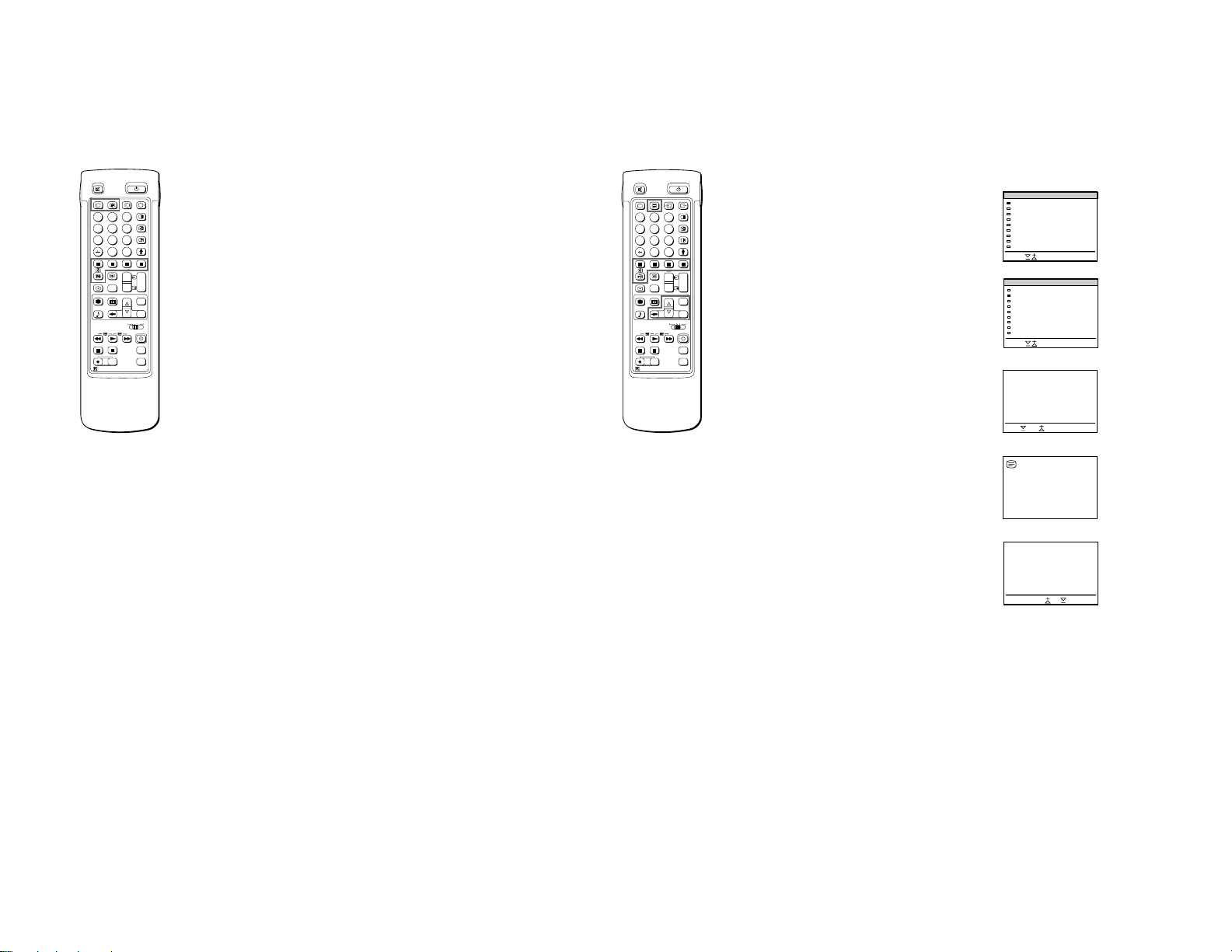
Overview
PROGR
RM-838
1
2
45
3
6
9
8
7
0
PROGR
PROGR
1
1
VTR 1-2-3
MDP
1
2
45
3
6
9
8
7
0
C
SAT
+
+
_
_
MENU
+
_
OK
+
_
RM-838
USE
MEM
RESET
SECTION 1
GENERAL
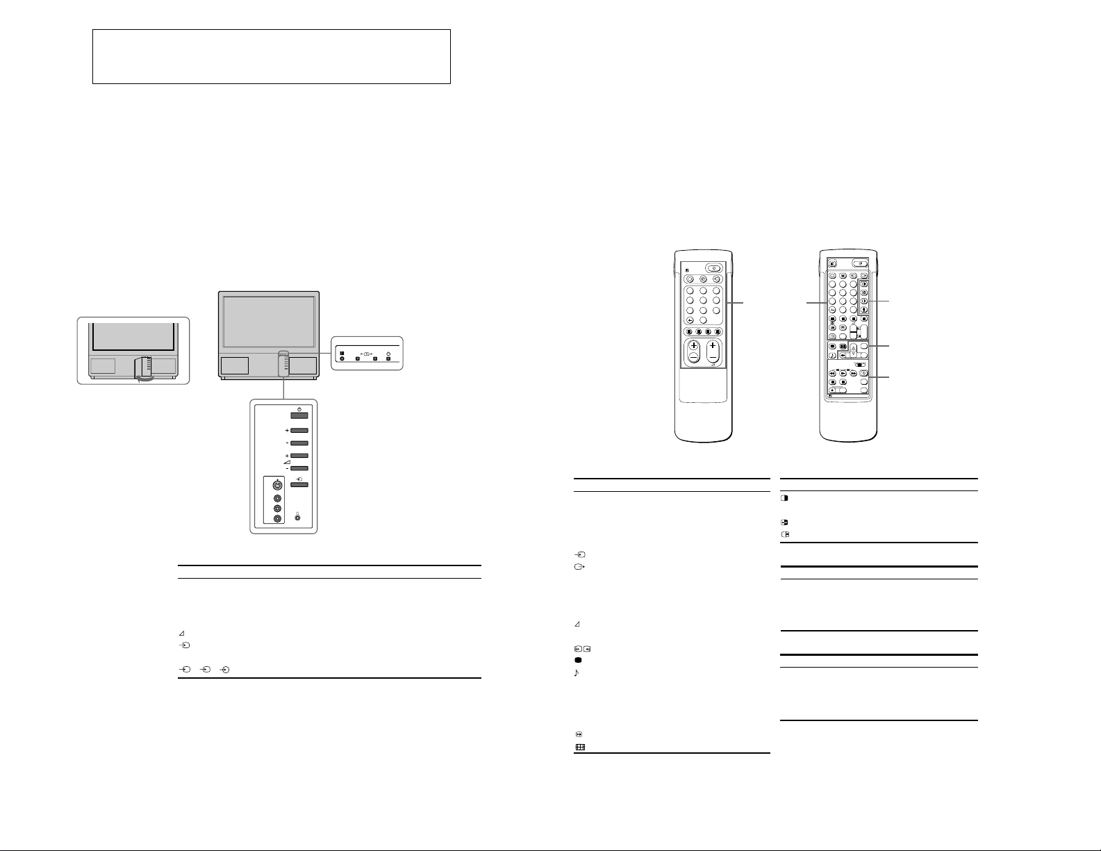
This section briefly describes the buttons and controls on the TV
set and on the Remote Commander. For more information, refer to
the pages given next to each description.
TV set-front
– 4 –
PROGR
Symbol
f
f
A-m -B
PROGR+/–
+/–
l
S
4
3, 3, 3
Name
Main power switch
Standby indicator
Stereo A/B indicators
Programme
Volume buttons
Input select buttons
Headphones jack
Input jacks (S video/video/audio)
AB
Refer to page
14
14
16
14
14
15
23
24
Note
The SAT button does not
operate with this TV.
TV/Teletext operation
Symbol
o
f
O
_
1,2,3,4,5,6,
7,8,9 and 0
–/-C
PROGR +/–
$
[
#
LLLL
Name
Mute on/off button
Standby button
TV power on/TV mode selector
button
Teletext button
Input mode selector
Output mode selector
Number buttons
Double-digit entering button
Direct channel entering button
Volume control button
+/–
Programme selectors
1
1
Teletext page access buttons
Picture adjustment button
Sound adjustment button
On-screen display button
Teletext hold button
Time display button
Fastext buttons
“Freeze” button
Button to change Screen Format
Remote commander
Simple side
Refer to page
15
14
14
15
15
24
14
14
10
14
14
20
16
16
15
20
15
20
15
15
TV/Teletext
operation
Full-Function side
PAP (Picture-and-picture) operation
Symbol
C
Name
PAP on/off button
PAP source selector
Swap button
PAP freeze button
Menu operation
Symbol
MENU
>+/ ?–
OK
@
Name
Menu on/off button
Select buttons
OK(confirming)button
Back button
Video operation
Symbol
VTR1/2/3,
MDP
;; - :: L
J a f
PROGR +/–
Name
Video equipment selector
Video equipment operation
buttons
PAP operation
Menu operation
Video operation
Refer to page
18
18
18
18
Refer to page
7
7
7
7
Refer to page
26
26
5
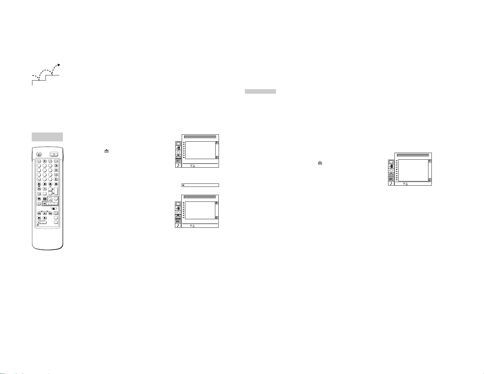
Getting Started
LANGUAGE
English
Deutsch
Français
Italiano
Español
Nederlands
Português
Suomi
Svenska
E ŁvØxÆ
Türkçe
Select and press OK
Select
+
_
OK
Step 2 T uning in to TV Stations
– 5 –
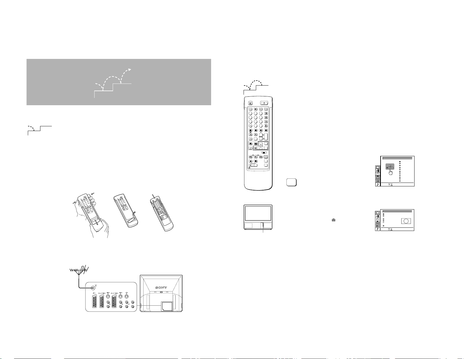
Step 1 Preparation
2
1
1
Check the supplied accessories
When you’ve taken everything
out of the carton, check that you
have these items:
• RM-838 Remote Commander
• One IEC designation R6 battery
• Wrench (1)
• Bracket (2)
• Dust Remover (1)
Insert the battery into the Remote Commander
2
RM-838
3
2
6
1
5
9
4
8
1
7
0
PROGR
Note: Always remember
to dispose of used
batteries in an
enviromental friendly
way.
6
3
Remove the cover. Check the correct
Connect the aerial
Fit an IEC aerial connector attached to 75-ohm coaxial cable (not
supplied) to the ) socket at the rear of the TV.
2
1
1
1
45
7
MEM
RM-838
2
Once you have set up the TV, you can choose the language of the
menu. Then, you should preset the channels (up to 100 channels)
by choosing either the automatic or manual method. The
automatic method is easier if you want to preset all receivable
2
3
6
9
8
0
C
PROGR
+
+
1
_
_
1
SAT
+
MENU
_
OK
VTR 1-2-3
MDP
USE
+
PROGR
RESET
_
channels at once. Use the manual method if you only have a few
channels and want to preset channels one by one.
Before you begin
• Check that the Full-Function side of the Remote Commander is
visible.
• Locate Menu operation buttons on the Remote Commander.
They are shaded in the illustration at the left.
Choose a language
1
1 Press f on the TV.
The TV will switch on. If the standby indicator on the TV is lit, press
O
or a number button on the Remote Commander.
2 Press the MENU button.
The LANGUAGE menu appears. (See Fig. 1.)
MENU
1
RM-838
3
2
1
6
5
4
9
8
7
0
PROGR
4
3
2
6
1
5
9
4
8
C
7
0
PROGR
+
1
+
_
1
3
3
_
MENU
SAT
+
OK
_
MDP
VTR 1-2-3
+
PROGR
RM-838
2
f
Refit the outside cover
making sure that the FullFunction side is visible to use
the menu in step 2.
To go back to main
menu
Keep pressing @.
To go back to the
normal TV picture
Press MENU. Normal
TV picture will be
restored after one
minute if menu functions
are not selected.
Note on the Demo
function
If you choose Demo in
the Installation menu,
you can see a sequential
demonstration of the
menu functions.
Press MENU to stop the
function.
L/G/S/I
R/D/D/D
L/G/S/I
R/D/D/D
polarities.
L/G/S/I
L/G/S/I
R/D/D/D
R/D/D/D
3 Select the language you want with > + or ? – and press OK.
Display the menu
2
Press MENU.
The main menu appears. (See Fig. 2.)
Using > + or ? – select the symbol
and press OK.
Now, choose one of the methods described overleaf:
“Preset Channels Automatically”
or
“Preset Channels Manually”
Fig. 1
SCREEN MODE
Screen Mode
Screen Position
Strobe
PAP
Clip Board
Auto 16:9
Select and press OK
Fig. 2
[ ]zoom
[ ]
0
[on]
[off]
[off]
7
– 6 –
To go back to the main
menu
Keep pressing @.
To stop automatic
channel presetting
Press @ on the Remote
Commander.
Notes
• After presetting the
channels automatically,
you can check which
channels are stored on
which programme
positions.
For details, see
“Displaying the
Programme Table” on
page 15.
• You can sort the
programme positions to
have them appear on
screen in the order you
like. For details, see
“Sorting Programme
Positions” on page 10.
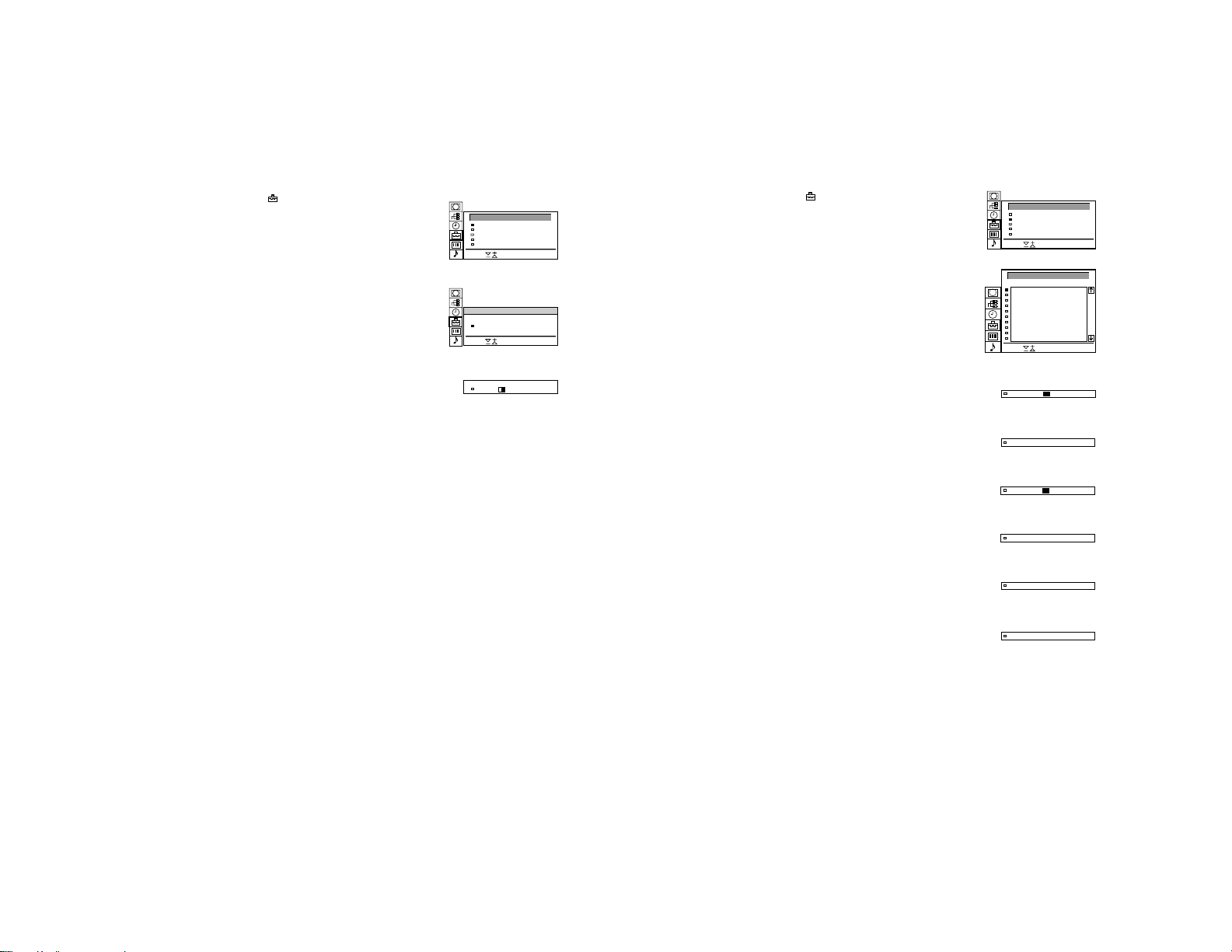
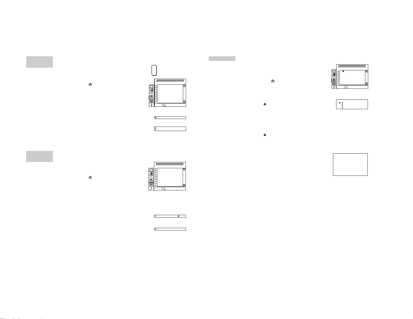
Preset channels automatically
3
1 Select the symbol for “Preset” with >+ or ?– and press OK.
The PRESET menu appears. (See Fig. 3.)
2 Select “Auto Programme” with >+ or ?– and press OK.
The AUTO PROGRAMME menu appears. (See Fig. 4.)
3 Press OK.
Select if necessary the TV broadcast system (B/G for Western
European or D/K for Eastern European countries) with >+ or ?–
and press OK. The first element of the “PROG” number will be
highlighted.
4 Select the programme (number button) from which you want to
start presetting. Select the first element of the double-digit number
with >+ or ?– or the number buttons (e.g., For “04,” select “0”
here) and press OK.
The second element of “PROG” will be highlighted.
5 Select the second element of the double-digit number with >+ or
?– or the number buttons (e.g., For “04,” select “4” here) (See Fig.
5) and press OK.
6 Select “C” or “S” with >+ or ?– and press OK.
The automatic channel presetting starts.
When presetting is finished, the preset menu reappears. All
available channels are now stored on successive number buttons.
Press menu to restore normal TV picture.
PRESET
Auto Programme
Manual Programme Preset
Programme Sorting
Parental Lock
Installation
Select and press OK
Fig. 3
AUTO PROGRAMME
SYS PROG
B/G
Select and press OK
Fig. 4
SYS PROG
B/G
Fig. 5
C25CH–
C25CH–
LABEL
LABEL
Use this method if there
are only a few channels
in your area to preset or if
you want to preset
channels one by one.
You may also allocate
programme numbers to
various video input
sources.
If you have made a
mistake
Press @ to go back to
the previous position.
––––01
––––04
To return to the main
menu
Keep pressing @.
To go back to the
normal TV picture
Press MENU.
To tune in a channel by
frequency
After selecting F in step 6,
enter three digits using
the number buttons.
Preset channels manually
3
1 Select the symbol for “Preset” with >+ or ?– and press OK.
The PRESET menu appears. (See Fig. 6.)
2 Select “Manual Programme Preset” with >+ or ?– and press OK.
The MANUAL PROGRAMME PRESET menu appears. (See Fig.
7.)
3 Using >+ or ?–, select the programme position (number button) to
which you want to preset a channel, and press OK.
4 Select, if necessary the TV broadcast system or a video input
source (EXT)) with >+ or ?–.
5 Then press OK. The CH position will be highlighted. (See Fig. 8.)
6 Using >+ or ?–, select C (to preset a regular channel), S (cable
channel) or F (to tune in by frequency) and press OK.
The first element of the “CH” number will be highlighted.
If you have selected EXT in step 5, select the video input source
with >+ or ?–. (See Fig. 9.)
There are two ways to preset channels, If you know the channel
number, go to step “7-Manual,”
or
If you don’t know the channel number, go to step “7-Search.”
7 Manual
-a Select the first element of the “CH” number with >+ or ?– or the
number buttons and press OK.
The second element of the “CH” number will be highlighted.
-b Select the second element of the number with >+ or ?– or the
number buttons.
The selected number appears. (See Fig. 10.)
-c Press OK
The “SEARCH” position is highlighted and the selected channel is
now stored. (See Fig. 11.)
-d Press OK until the cursor appears by the next programme position.
-e Repeat steps 3 to 7 to preset other channels.
7 Search
-a Press OK repeatedly until the colour of the SEARCH position
changes.
-b Start searching for the channel with >+ (up) or ?– (down).
The CH position changes colour. (See Fig. 12.)
The CH number starts counting up or downwards. When a
channel is found, it stops. (See Fig. 13.)
-c Press OK if you want to store this channel. If not, press >+ or ?–
to continue channel searching.
PRESET
Auto Programme
Manual Programme Preset
Programme Sorting
Parental Lock
Installation
Select and press OK
Fig. 6
MANUAL PROGRAMME PRESET
PROG
SYS
CH
SEARCH LABEL
1
B/G
C21
2
B/G
C34
3
B/G
C33
4
B/G
C45
5
B/G
C02
6
B/G
C08
7
B/G
C10
8
B/G
C12
9
B/G
C20
10
B/G
C59
Select and press OK
Fig. 7
2 C –––––21B/G off
Fig. 8
3 AV1 –––––EXT
Fig. 9
2 C –––––21B/G off
Fig. 10
2 C –––––35B/G off
Fig. 11
2 C –––––35B/G off
Fig. 12
2 C –––––50B/G
Fig. 13
off
-----
off
-----
off
-----
off
-----
off
-----
off
-----
off
-----
off
-----
off
-----
off
-----
4$
-d Press OK until the cursor appears by the next programme position.
-e Repeat steps 3 to 7 to preset other channels.
8
9
– 7 –
FURTHER PROGRAMME PRESET
PROG
1
2
3
4
5
6
7
8
9
10
Select and press OK
ATT
0
0
- 1
- 1
0
- 1
- 1
- 1
- 1
- 1
VOL
on
on
on
on
on
on
on
on
on
on
IN-AMP AFT
on
on
- 1
- 1
on
- 1
- 1
- 1
- 1
- 1
off
off
off
off
off
off
off
off
off
off
Additional Presetting Functions
2
1
PROGRAMME
SORTING
2
1
3
6
45
9
8
7
0
C
PROGR
+
+
1
_
_
1
SAT
+
MENU
_
OK
VTR 1-2-3
MDP
MEM
USE
+
PROGR
RESET
_
RM-838
For higher programme
positions
The display scrolls
automatically.
If you have made a
mistake
Press @ to go back to
the previous position
To go back to main
menu
Keep pressing @.
To go back to the
normal TV picture
Press MENU.
This section shows you additional presetting functions such as
sorting or skipping programme positions, captioning a station
name, manual fine-tuning, and using the parental lock.
Before you begin
• Check that the Full Function side of the Remote
Commander is visible.
• Locate the Menu operation buttons.
Sorting Programme Positions
With this function, you can sort the programme positions to a
preferable order.
1 Press MENU to display the main menu.
2 Select the symbol
The PRESET menu appears.
3 Select “Programme Sorting” with >+ or ?– and press OK.
The PROGRAMME SORTING menu appears. (See Fig. 14.)
4 Using >+ or ?–, select the programme position you want to move
to another and press OK.
The colour of the selected position changes. (See Fig. 15.)
5 Using >+ or ?–, select the programme position to which you want
to move the channel of the programme position selected in step 4
and press OK. Now the programme positions have been sorted.
(See Fig. 16.)
6 Repeat steps 4 and 5 to sort other programme positions.
for “Preset” with >+ or ?– and press OK.
PROGRAMME SORTING
PROG
Move PR 8 to PR - -
Select and press OK
Fig. 14
8 BBC1C15
Fig. 15
PROGRAMME SORTING
PROG
Move PR 1 to PR - -
Select and press OK
Fig. 16
1
2
3
4
5
6
7
8
1
2
3
4
5
6
7
8
CH LABEL
C03
BBC 2
C04
C07
MBC
C09
-----
C12
-----
C13
-----
C14
-----
C15
BBC 1
CH LABEL
C15
BBC 1
C03
BBC 2
C04
C07
MBC
C09
-----
C12
-----
C13
-----
C14
-----
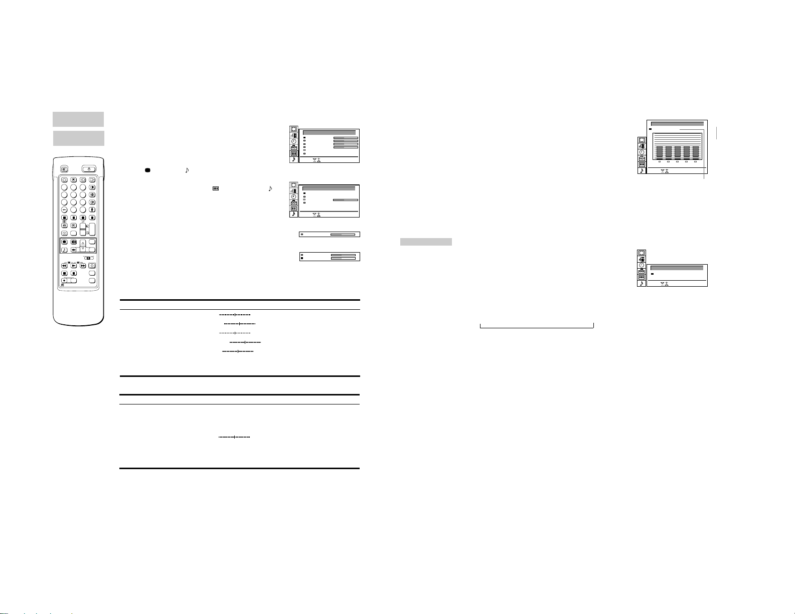
INSTALLATION
Using “Further Programme
Preset”
Using the menu “further Programme Preset” you can
a) in case of a strong local aerial signal (striped picture) attenuate the
signal individually for each programme position (RF attenuator).
b) individually adjust and store the volume level of each channel
(Volume offset).
c) in case of a strong sound signal (distorted sound), attenuate the
sound signal for each programme position.
d) use the manual fine tuning to obtain a better picture reception, if
ITV
ITV
To reactivate AFT
(Automatic Fine
Tuning)
Repeat from the
beginnig and select “ON”
in step 5.
the picture is distorted. Normally the AFT (automatic fine tuning) is
operating.
1 Press MENU to display the main menu.
2 Select the symbol
The PRESET menu appears.
3 Select “Installation” with >+ or ?– and press OK. The
INSTALLATION menu appears.
4 Select “Further Programme Preset” with >+ or ?– and press OK.
The FURTHER PROGRAMME PRESET menu appears (See Fig.
17).
5 Using >+ or ?– select the desired programme position and press
OK once to select a) “ATT” (RF Attenuator), twice to select b)
“VOL” (Volume offset), three times to select c) “IN-AMP” (Input
Amplifier) or four times to select d) AFT (Automatic Fine Tuning).
The selected item changes colour.
for “Preset” with >+ or ?– and press OK.
To adjust or change:
a) RF attenuator (ATT)
Using >+ or ?– select “On” for the selected programme position.
Press OK to confirm the selection. Repeat step 5 to attenuate
other programme positions.
b) Volume offset (VOL)
Using >+ or ?– you can adjust the volume level for the selected
programme position within a range form –7 to +7.
Press OK to store the volume level.
Repeat step 5 to set the volume level for other programme
positions.
c) IN-AMP (input amplifier)
Using >+ or ?– select “Off” for the selected programme position.
Press OK to confirm the selection. Repeat step 5 to switch off the
input amplifier for other programme positions.
d) AFT
Using >+ or ?– you can fine-tune the channel within a range from
–15 to +15. Press OK to store the fine-tuned level. Repeat step 5
to fine-tune the other channels.
6 Press MENU to return to the normal TV mode.
Fig. 17
10
11
– 8 –
MANUAL
PROGRAMME
PRESET
If you have made a
mistake
Press @ to go back to
the previous position.
To go back to main
menu
Keep pressing @.
To go back to the
normal TV picture
Press MENU.
MANUAL
PROGRAMME
PRESET
Skipping Programme Positions
You can skip unused programme positions when selecting
programmes with PROGR +/– buttons. However, the skipped
programmes may still be called up when you use the number
buttons.
1 Press MENU to display the main menu.
2 Select the symbol
The PRESET menu appears.
3 Select “Manual Programme Preset” with >+ or ?– and press OK.
The MANUAL PROGRAMME PRESET menu appears. (See Fig.
18.)
4 Using >+ or ?–, select the programme position which you want to
skip and press OK.
The “SYS” position changes colour.
5 Press >+ or ?– until “– – –” appears in the SYSTEM position.
(See Fig. 19.)
6 Press OK. (See Fig. 20.)
When you select programmes using the PROGR +/– buttons, the
programme position will be skipped.
for “Preset” with >+ or ?– and press OK.
7 Repeat steps 4 to 6 to skip other programme positions.
Captioning a Station Name
Programme names are usually automatically taken from Teletext if
available, You can also “name” a channel or an input video source
using up to five characters (letters or numbers) to be displayed on
the TV screen (e.g. BBC1). Using this function, you can easily
identify which channel or video source you are watching.
1 Press MENU to display the main menu.
2 Select the symbol for “Preset” with >+ or ?– and press OK.
The PRESET menu appears.
3 Select “Manual Programme Preset” with >+ or ?– and press OK.
The MANUAL PROGRAMME PRESET menu appears. (See Fig.
21.)
4 Using >+ or ?–, select the programme position you want to
caption and press OK repeatedly until the first element of the
LABEL position is highlighted.
5 Select a letter or number with >+ or ?– and press OK.
The next element will be highlighted.
Select other characters in the same way. If you want to leave an
element blank, select - and press OK. (See Fig. 22.)
6 After selecting all the characters, press OK repeatedly until the
cursor appears by the next programme position (at the left margin).
Now the caption you chose is stored. (See Fig. 23.)
7 Repeat steps 5 and 6 to caption names for other channels.
PROGR
+
_
MANUAL PROGRAMME PRESET
PROG
SYS
CH
SEARCH LABEL
1
B/G
C21
2
B/G
C24
3
B/G
C25
4
B/G
C27
5
B/G
C28
6
B/G
C22
7
B/G
C26
8
B/G
C25
9
B/G
C23
10
B/G
C29
Select and press OK
Fig. 18
3 –––
Fig. 19
3 –––
4 B/G
Fig. 20
MANUAL PROGRAMME PRESET
PROG
SYS
CH
SEARCH LABEL
1
B/G
C21
2
B/G
C24
3
B/G
C25
4
B/G
C27
5
B/G
C28
6
B/G
C22
7
B/G
C26
8
B/G
C25
9
B/G
C23
10
B/G
C29
Select and press OK
Fig. 21
2 C S––––25B/G off
Fig. 22
2CSONY25B/G off
Fig. 23
PARENTAL LOCK
off
-----
off
-----
off
-----
off
-----
off
-----
off
-----
off
-----
off
-----
off
-----
off
-----
If you try to select a
programme that has
been blocked
The message
“LOCKED” appears on
the blank TV screen.
Parental Lock
You can prevent undesirable broadcasts from appearing on the
screen. We suggest you use this function to prevent children from
watching programmes which you consider unsuitable.
1 Press MENU to display the main menu.
2 Select the symbol
The PRESET menu appears.
3 Select “Parental Lock” with >+ or ?– and press OK.
The PARENTAL LOCK menu appears. (See Fig. 24.)
4 Using >+ or ?–, select the programme position you want to block
and press OK.
The symbol
indicating that this programme is now blocked. (See Fig. 25.)
5 Repeat step 4 to block other programme positions.
for “Preset” with >+ or ?– and press OK.
appears in front of the programme number
PARENTAL LOCK
Select and press OK
Fig. 24
PROG CH LABEL
Fig. 25
PROG
CH LABEL
0
AV1
1
C25
2
C42
3
C26
4
C34
5
C35
6
C36
7
C37
0 AV1 VHS
1 C25 BBC 2
2 C42 BBC 1
3 C26 C 4
BBC 2
BBC 1
-----
-----
-----
VHS
C 4
ITV
Cancelling blocking
1 On the PARENTAL LOCK menu, select the programme position
you want to unblock with >+ or ?–.
2 Press OK.
The symbol
cancelled.
disappears indicating that the blocking has been
T uning in a Channel Temporarily
You can tune in to a channel temporarily, even when it has not
been preset. Use the buttons on the Full-Function side of the
Remote Commander.
off
-----
off
-----
off
-----
off
-----
off
-----
off
-----
off
-----
off
-----
off
-----
off
-----
1 Press C on the Remote Commander. For cable channels, press C
twice.
The indication “C” ( “S” for cable channels) appears on the screen.
(See Fig. 26.)
2 Enter the double-digit channel number using the number buttons
(e.g. for channel 4, first press 0, then 4).
The channel appears.
However, the channel will not be stored.
Fig. 26
C - -
12
13

– 9 –
1
2
3
4
5
6
7
8
9
10
BBC
SAT
TV5
C02
C15
RTL
SKY
S34
AV1
MTV
Operating Instructions
Watc hing the TV
This section explains the basic functions you use while watching
TV. Most of the operations can be done using the simple side of
the Remote Commander.
Switching the TV on and off
Switching on
Depress f on the TV.
Switching off temporarily
Press f on the Remote Commander.
The TV enters standby mode and the standby indicator on the front
of the TV lights up in red.
To switch on again
Press O, PROGR +/–, or one of the number buttons on the
Remote Commander.
When the power is turned on again right after the power is turned
off, the projection TV will enter standby mode with the f (standby)
indicator flashing. After the set cools down, the power will come
on.
Switching off completely
Depress f on the TV and indicator on the front of the TV lights up
in amber.
Selecting TV Programmes
Press PROGR +/– or press the number buttons.
To select a double-digit number
Press -/--, then the numbers.
For example, If you want to choose 23, press -/--, 2 and 3.
Adjusting the V olume
Press +/–.
Operating the TV Using the
Buttons on the TV
To select the programme number, press the PROGR +/– buttons.
To adjust the volume, press the
To select the video input picture, press the
To reset picture and sound controls to the factory preset level
(RESET function), press PROGR +/– buttons simultaneously.
RM-838
2
1
3
6
45
9
8
7
0
PROGR
If no picture appears
when you depress f
on the TV and if the
standby indicator on
the TV is lit, the TV is in
standby mode.
Press O or one of the
number buttons to
switch it on.
14
+/– buttons.
button.
AB
Watching Teletext or Video Input
Watching teletext
1 Press _ to view the teletext.
2 For teletext operation, enter a 3-digit page number with the number
buttons to select a page.
For fastext operation, press one of the coloured buttons.
For both operations, press V (PAGE + ) for the next page or
U (PAGE – ) for the preceding page.
3 To go back to the normal TV picture, press O .
Watching a video input picture
1 Press repeatedly until the desired video input appears.
For details of the teletext
operation, refer to
page 20.
For details of the video
input picture, refer to
page 24.
2 To go back to the normal TV picture, press O.
More Convenient Functions
Use the Full-Function side of the Remote Commander.
Displaying the on screen indications
• Press $ once to display all the indications. They will disappear
after a few seconds.
• Press $ twice to have the programme number and label stay on
screen. Press twice again to make the indications disappear.
PROGR
Muting the sound
Press o.
To resume normal sound, press o again.
2
1
3
6
45
9
8
7
0
C
PROGR
+
+
1
_
_
1
PROGR
SAT
+
MENU
_
OK
VTR 1-2-3
MDP
MEM
USE
+
PROGR
RESET
_
RM-838
Displaying the time
Press #. This function is available only when teletext is broadcast.
To make the time display disappear, press # again.
Displaying the Programme Table
Press OK. A Programme Table will be displayed on the left side of
the TV screen. (See Fig. 27.)
Selecting TV programmes
Press PROGR +/– or select the desired programme position using
>+ or ?– and press OK.
To make the Programme Table disappear, press MENU.
Freezing the Picture
When watching the TV you have the possibility to “freeze” the
picture. Press
TV picture.
. Press the button again to return to the normal
Fig. 27
Changing the Screen format
Press repeatedly to change the Screen mode as follows:
4:3 (4:3 picture)
A Smart (imitation of 16:9 for 4:3 broadcast)
A Zoom (imitation of 16:9 for movies broadcast in
cinemascopic format)
or
A Wide (for 16:9 broadcast).
See also page 19 for more information.
15
Adjusting and Setting the TV Using
the Menu
– 10 –
PICTURE
CONTROL
SOUND
CONTROL
2
1
3
6
45
9
8
7
0
C
PROGR
+
+
1
_
_
1
SAT
+
MENU
_
OK
VTR 1-2-3
MDP
MEM
USE
+
PROGR
RESET
_
RM-838
If you have made a
mistake
Press @ to go back to
the previous position.
To go back to the main
menu
Keep pressing @.
Notes
• HUE is only available for
NTSC colour systems.
When watching a video
input source with
stereo sound
You can select DUAL
SOUND to change the
sound.
Adjusting the Picture and Sound
Although the picture and sound are adjusted at the factory, you can
adjust them to suit your own taste. You can also select dual sound
(bilingual) programmes when available or adjust the sound for
listening with the headphones. Also you have the possibility to
adjust the sound to your individual taste using the Graphic
Equalizer and special Sound effects.
1 Press
2 Using >+ or ?–, select the item you want to adjust and press OK.
3 Adjust the setting with >+ or ?– and press OK.
4 Repeat steps 2 and 3 to adjust other items.
5 Press MENU to return to TV picture.
Effect of each control
PICTURE CONTROL
SOUND CONTROL
Graphic Equalizer
Dual Sound
Headphones:
2 Volume
2 Dual Sound
(for picture) or (for sound) on the Remote Commander.
or
Press MENU and select the symbol
Sound Control, then press OK.
The PICTURE CONTROL or SOUND CONTROL menu appears.
(See Fig. 28 or Fig. 29.)
for Picture Control or
The selected item changes colour. (See Fig. 30.)
The cursor appears beside the next item (at the left margin). (See
Fig. 31.)
For the effect of each control, see the table below.
Effect
Contrast
Brightness
Colour
Hue
Sharpness
RESET
Resolution
Less More
Darker
Less
Greenish
Softer
Brighter
More
Reddish
Sharper
Resets picture to the factory preset levels.
Normal high: obtain a high quality picture
Effect
(See page 17 for more information)
A: channel 1 B: channel 2 Stereo Mono
The selected mode of the A-m-B indicator on the TV lights up.
Less
A: channel 1 n B: channel 2 n PAP (if PAP is switched on you
can select the PAP sound for the headphones)
More
Stereo n Mono
PICTURE CONTROL
Contrast
Brightness
Colour
Sharpness
Reset
Resolution (high)
Select and press OK
Fig. 28
SOUND CONTROL
Grafic Equalizer
Dual Sound
2
Volume
Dual Sound (A)
2
Select and press OK
Fig. 29
Brightness
Fig. 30
Brightness
Colour
Fig. 31
Graphic Equalizer
Using this function you can individually adjust the sound by cutting
and boosting selected frequencies. You can also select between
the following modes:
Note: The modifications
made in “USER” mode
will be stored. All other
settings are reset to
factory-set level when
you change to another
[ ]mono
[ ]mono
mode.
Flat n Pop n Rock n Jazz n Vocal n User
1 Select “Sound Control” in the main menu, then select “Graphic
Equalizer” using >+ or ?– and press OK.
The GRAPHIC EQUALIZER menu appears (See Fig. 32).
2 Press OK. The colour of “Mode” changes. Select the desired
mode with >+ or ?– and press OK.
3 If you want to modify a mode, select the desired bar of a frequency
band using >+ or ?– and press OK. The selected frequency
changes colour. Using >+ or ?– adjust the level of frequency and
press OK. In this way you can adjust all 5 graphic bars.
GRAPHIC EQUALIZER
+
0
–
100 400 1K 4K 10K
Select and press OK
Fig. 32
[User]Mode:
Flat
Pop
Rock
Jazz
Vocal
User
4 Press MENU to return to the normal TV mode.
TIMER
To switch off the timer
Select “OFF” in step 3.
To check the
remaining time
Press $.
To go back to the
normal TV picture
Press MENU.
Using the Sleep Timer
You can select a time period after which the TV automatically
switches into standby mode.
1 Using >+ or ?– select the symbol t for “Timer” and press OK.
The TIMER menu appears (see Fig. 33).
2 Press OK.
The time period option changes colour.
3 Select the time period with >+ or ?–.
The time period (in minutes) changes as follows:
10 n 20 n 30 n 40 n 50 n 60 n 70 n 80 n 90
↑
4 After selecting the time period, press OK.
The cursor moves back to the left margin and the timer starts
counting.
One minute before the TV switches into standby mode, a message
is displayed on the screen.
TIMER
Sleep Timer [ ]10 Min
Select and press OK
Fib. 33
16
17
P AP (Picture and Picture)
off: OK
LIVELIVE
Strobe: Speed:
– 11 –
2
1
3
6
45
9
8
7
0
C
PROGR
+
+
1
_
_
1
SAT
+
MENU
_
OK
VTR 1-2-3
MDP
MEM
USE
+
PROGR
RESET
_
RM-838
Notes
• RGB input source
cannot be displayed in
PAP.
• PAP is not available in
the Zoom mode.
• The sound of the right
screen is only available
via the headphones.
• The picture quality of
the TV screen and
PAP may differ.
With this function you can display two screens at the same time. In
this way you can watch two TV programmes at the same time. Also
you can watch or monitor the video output from any connected
equipment (for example from a VCR) while watching TV or vice
versa. For information about connection of other equipment, refer
to page 23.
Main
TV picture
Switching PAP on and off
Press to display the screens in 8:9 format.
PAP screen
The PAP screen will be displayed next to the main TV screen.
The PAP screen will come from the source chosen when the TV
was last used.
To switch PAP off
Press
repeatedly.
Selecting PAP source
Press >.
The symbol > will be displayed at the bottom, left-hand corner of
the screen.
Press PROGR +/–, the number buttons or … to select the desired
source for the PAP screen.
Swapping screens
Press .
The main screen will switch the picture with the PAP screen.
8: 9 8: 9
AB BA
Freezing the picture
You have the possibility to “freeze” the picture of the PAP screen.
once to freeze and twice to return to the normal screen.
Press
16: 9
8: 9
A
AB
AA
/
AA
/
Freeze
Freeze
2
1
3
6
45
9
8
7
0
C
PROGR
+
+
1
_
_
1
SAT
+
MENU
_
OK
VTR 1-2-3
MDP
MEM
USE
+
PROGR
RESET
_
RM-838
When you want to
select the screen
mode
You can also select the
screen mode by
pressing the
on the Remote
Commander.
button
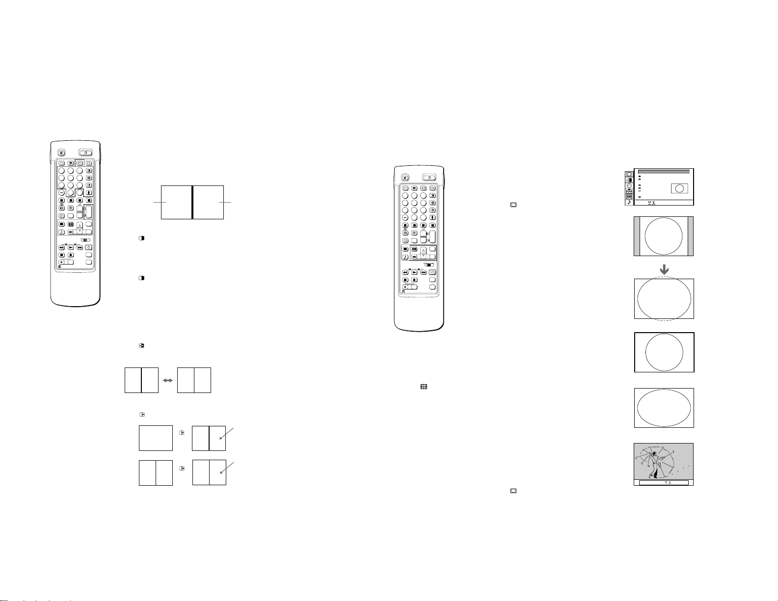
Operating Screen Mode/P AP using
the Menu
Using the Screen Mode menu you have the possibility to change
the aspect ratio for the TV display for wide screen effects, operate
the PAP Mode or reproduce the main picture image by image
(Strobe function).
1 Press MENU to display the main menu.
2 Select the symbol
OK. The SCREEN MODE menu appears (See Fig. 34).
You have the choice among the following modes:
4:3 for normal ratio 4:3 (See Fig. 35).
Smart: imitation of wide screen effect (16:9) for 4:3 broadcasts
Zoom imitation of wide screen effect (16:9) for movies broadcast
Wide: for 16:9 broadcasts (See Fig. 38).
a) Changing the Screen position (only for Zoom mode)
When using the Zoom mode part of the picture at the top and
bottom will be cut off. With the help of the function “Screen
position” you can move the screen up- or downwards in order to
see the cut-off part of the screen (e.g., to read the subtitles).
Using >+ or ?– select “Screen position” and press OK. The
selected item changes colour. Using >+ or ?– adjust the screen
position and press OK.
b) Strobe Mode
Using >+ or ?– select “Strobe” and press OK. Now the TV picture
is displayed image by image, creating a slow motion effect (See
Fig. 39). Using >+ or ?– select the speed of the motion (3
different speeds are available). Press OK to return to the normal
TV mode.
c) Switching PAP on and off
Using >+ or ?– select “PAP” and press OK. Using >+ or ?–
select “ON” to display the PAP screen in 8:9 format and “OFF” to
switch if off and press OK.
d) Freezing the PAP screen
Using >+ or ?– select “Clip Board” and press OK.
Using >+ or ?– select “On” to freeze the PAP screen and “Off” to
restore the normal picture.
for “Screen Mode” with >+ or ?– and press
(See Fig. 36).
in cinemascopic format (See Fig. 37).
or
Auto 16:9
If you preset Auto 16:9 to ON and the 16 : 9 format signal is being
transmitted, the screen mode automatically changes from any
mode to the 16 : 9 mode. When the 16 : 9 format programme is
finished, the screen mode automatically returns to the previous
mode.
1 Press MENU to display the main menu.
2 Select the symbol
OK. The SCREEN MODE menu appears.
3 Select “Auto 16:9” with >+ or ?– and press OK.
4 Select ON or OFF with >+ or ?– and press OK.
for “Screen Mode” with >+ or ?– and press
SCREEN MODE
Screen Mode
Screen Position
Strobe
PAP
Clip Board
Auto 16:9
Select and press OK
Fig. 34
Fig. 35
Fig. 36
Fig. 37
Fig. 38
Fig. 39
[ ]zoom
[ ]
0
[on]
[off]
[off]
18
19
T eletext
TELETEXT MENU
Select and press OK
User Pages
Index
Top/Bottom/Full
Text Clear
Subtitles
Reveal
Time Page
Subpage
Preset User Pages
Top Bottom OK Full
– 12 –
2
1
3
6
45
9
8
7
0
C
PROGR
+
+
1
_
_
1
SAT
+
MENU
_
OK
VTR 1-2-3
MDP
MEM
USE
+
PROGR
RESET
_
RM-838
Note
Teletext errors may
occur if the broadcasting
signals are weak.
With the simple side of
the Remote
Commander
You can switch teletext
on and off, operate
Fastext, and directly
select page numbers.
Note
Fastext operation is only
possible, if the TV station
broadcasts Fastext
signals.
20
TV stations broadcast an information service called Teletext via
the TV channels.Teletext service allows you to receive various
information pages such as weather reports or news at any time
you want. For advanced teletext operation, use the buttons on the
Full-Function side of the Remote Commander.
Direct Access Functions
Switching Teletext on and off
1 Select the TV channel which carries the teletext broadcast you
want to watch.
2 Press _ to switch on teletext.
A teletext page will be displayed (usually the index page).
If there is no teletext broadcast, “No text available” is displayed on
the information line at the top of the screen.
To switch teletext off
Press O.
Selecting a teletext page
With direct page selection
Use the number buttons to input the three digits of the chosen
page number.
If you have made a mistake, type in any three digits. Then re-enter
the correct page number.
With page-catching
1 Select a teletext page with a page overview (e.g. index page).
2 Press OK. Using >+ or ?–, select the desired page. “Page
Catching” will be displayed on the information line. Press OK.
The requested page will appear in a few seconds.
Press _ to resume normal teletext reception.
Accessing next or preceding page
Press g (PAGE+) or G (PAGE-).
The next or preceding page appears.
Superimposing the teletext display on the TV programme
• Press _ once in teletext mode or twice in TV mode.
• Press _ again to resume normal teletext reception.
Preventing a teletext page from being updated
• Press [ (HOLD). The HOLD symbol “[” is displayed on the
information line.
• Press _ to resume normal teletext reception.
Using Fastext
With Fastext you can access pages with one key stroke.
When a Fastext page is broadcast, a colour-coded menu will
appear at the bottom of the screen. The colours of this menu
correspond to the red, green, yellow and blue buttons on the
Remote Commander.
Press the corresponding coloured button on the Remote
Commander which corresponds to the colour-coded menu. The
page will be displayed after a few seconds.
2
1
3
6
45
9
8
7
0
C
PROGR
+
+
1
_
_
1
SAT
+
MENU
_
OK
VTR 1-2-3
MDP
MEM
USE
+
PROGR
RESET
_
RM-838
Note
Some of the features
may not be available
depending on the
teletext service.
Press OK to select “OFF”
for the TIME PAGE
setting to cancel the
request.
Using the T elete xt Menu
This TV is provided with a menu-guided teletext system. When
teletext is switched on, you can use the menu buttons to operate
the teletext menu. Select the teletext menu functions in the
following way:
1 Press MENU. The menu will be superimposed on the teletext
display. (See Fig. 40.)
2 Using >+ or ?–, select the teletext function you want and press
OK. (See Fig. 41.)
USER PAGES/PRESET USER PAGES
See page 22 for information about presetting and operating the
user pages.
INDEX
The index will give you an overview of the contents of the teletext
and the page numbers.
TOP/BOTTOM/FULL
For convenient reading of a teletext page, you can enlarge the
teletext display with the ability to scroll up and down. After having
selected the function, an information line Top/Bottom/Full will be
displayed. (See Fig. 42.)
Press >+ for “Top” to enlarge the upper half. For “Bottom” keep
pressing ?–, to enlarge the lower half. Press OK for “Full” to
resume the normal size.
Press _ to resume normal teletext reception.
TEXT CLEAR
After selecting the function, you can watch a TV programme while
waiting for a teletext page to be captured. (The symbol changes
colour.) (See Fig. 43.)
Press _ to resume normal teletext reception.
SUBTITLES
Your teletext service will inform you if a TV programme is subtitled.
After having selected the function the subtitles will be displayed.
REVEAL
Sometimes pages contain concealed information, such as
answers to a quiz. The reveal option lets you disclose the
information. After having selected the function, an information line
“REVEAL ON/OFF” will be displayed. (See Fig.44.)
Using >+ or ?–, select ON to reveal the information or OFF to
conceal it again.
Press _ to resume normal teletext reception.
TIME PAGE
Your teletext service will inform you, if a time coded page is
available. You may have a page (e.g., an alarm page) displayed at
a certain time.
1 An information window will be displayed at the bottom of the page.
Using >+ or ?– select “ON” and press OK.
2 To select the desired page, enter three digits for the page number
(e.g., 452) using the number buttons.
3 To select the desired time, enter four digits for the desired time
(e.g., 1800) using the number buttons. Press MENU.
The selected time is displayed at the top in the left-hand corner.
At the requested time, the page will be displayed.
Press _ to resume normal teletext mode.
Fig. 40
TELETEXT MENU
User Pages
Index
Top/Bottom/Full
Text Clear
Subtitles
Reveal
Time Page
Subpage
Preset User Pages
Select and press OK
Fig. 41
Fig. 42
Fig. 43
Fig. 44
onReveal off
21
Connecting and Operating Optional
R/D/D/D
L/G/S/I
R/D/D/D
L/G/S/I
R/D/D/D
L/G/S/I
PROGR
R/D/D/D
L/G/S/I
Equipment
– 13 –
To cancel the request
Select Subpage and
press OK.
If two broadcasting
stations use the same
Teletext
You can preset one
bank to 2 different
programme positions.
22
SUBPAGE
You may want to select a particular teletext page from several
subpages which are rotated automatically. After having selected
the function, an information line will be displayed.
To select the desired subpage, enter four digits using PROGR +/–
or the number buttons (e.g., enter 0002 for the second page of a
sequence).
User Page Bank System
You can store up to 30 pages in the “Teletext page band system”.
In this way you have quick access to the pages you watch
frequently.
Storing pages
There are 5 “banks” (A to E) for 5 teletext stations. In each bank
you can store 6 preferred pages (P1 to P6).
1 Press _ (if Teletext is not on already) and MENU to show the
TELETEXT MENU display.
2 Select PRESET USER PAGES with >+ or ?– and press OK.
3 Select the desired bank with >+ or ?– and press OK. The cursor
will go to the first position (P1) of the preferred pages.
4 Input the three digits of your first preferred page with the number
buttons and press OK.
The cursor will go to the second position.
5 Repeat step 4 for the other 5 page numbers you want to preset. If
you do not want to preset all 6 page numbers available, press OK
without inserting any number. After having finished the presetting
press OK repeatedly until the cursor appears besides the next bank
at the left margin.
6 Select Allocate Bank with >+ or ?– and press OK.
7 Select the programme position for which you have preset pages
with >+ or ?– and press OK. (See Fig. 45.)
8 Select the desired bank with >+ or ?– (Banks A to E are available)
and press OK.
9 Repeat steps 3 to 8 for the other 4 banks available.
Displaying User Pages
1 Select MENU.
2 Select User Pages with >+ or ?– and press OK.
A table of the stored preferred pages will be displayed. (See Fig.
46)
3 Select the desired page with >+ or ?– and press OK. The page
will be displayed after some seconds.
or
You can use the coloured buttons on the Remote Commander to
have quick access to the first four User pages. Page 1 corresponds
to the red button, P2 to the green one, P3 to the yellow one and P4
to the blue button.
To select the desired page press the respective coloured button
while you are in TV mode. Now the Page number of this teletext
page will appear in white at the top in the left-handed comer of the
TV screen. When the page number changes colour, the page is
available. Press the coloured button again to display the page.
PRESET USER PAGES
BANK
P1
P2
P3
A
300
255
456
B
200
120
301
C
100
220
300
D
128
321
255
E
400
238
240
Allocate Bank
PROG LABEL BANK PROG LABEL BANK
00
VHS
–
01
BBC1
A
02
BBC2
C
Select and press OK
Fig. 45
USER PAGES - BANK B
PAGE 300
PAGE 200
PAGE 203
PAGE 500
PAGE 234
PAGE 159
Select and press OK
Fig. 46
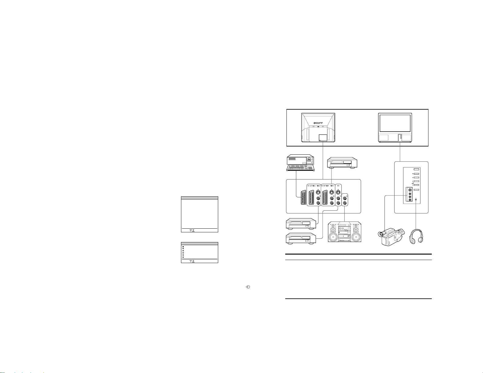
Connecting Optional Equipment
You can connect optional audio-video equipment to this TV such as a
VCR, video disc player, and stereo system.
To connect a VCR
using the ) terminal
Connect the aerial output
of the VCR to the aerial
terminal ) of the TV.
We recommend that you
tune in the video signal to
programme number “0.”
For details see “Preset
channels manually” on
page 9.
If the picture or the
sound is distorted
Move the VCR away from
P4
P5
P6
234
200
179
303
550
345
444
118
127
04
MTV
D
05
SKY
B
06
ITV
C
the TV.
S/video Input
(Y/C input)
Video signals may be
separated into Y
(luminance or brightness)
and C (chrominance)
signals.
Separating the Y and C
signals prevents them
from interfering with one
another, and therefore
improves picture quality
(especially luminance).
This TV is equipped with
3 S Video input jacks
through which these
separated signals can be
input directly.
When connecting a
monaural VCR
Connect only the white
jack to both the TV
and VCR.
Note on playing video
games:
Games that involve
shooting at the screen
with an electronic gun or
similar device cannot be
played with this TV.
1
2
Acceptable input signal
1 Normal audio/video and RGB signal
2 Normal audio/video and S video signal
3 Normal audio/video and S video signal
4 Normal audio/video and S video signal
5 No inputs
6 No inputs
4
3
5
6
Available output signal
Video/audio from TV tuner
Video/audio from selected source
No outputs
Video/audio displayed on TV screen (monitor out)
S/video/audio signal displayed on TV screen (monitor
out)
Audio signal
23
– 14 –
Selecting input with
PROGR +/– or number
buttons
You can preset video
input sources to the
programme positions so
that you can select them
with PROGR +/– or
number buttons. For
details, see “Preset
channels manually” on
page 9.
2
1
3
6
45
9
8
7
0
C
PROGR
+
+
1
_
_
1
SAT
+
MENU
_
OK
VTR 1-2-3
MDP
MEM
USE
+
PROGR
RESET
_
RM-838
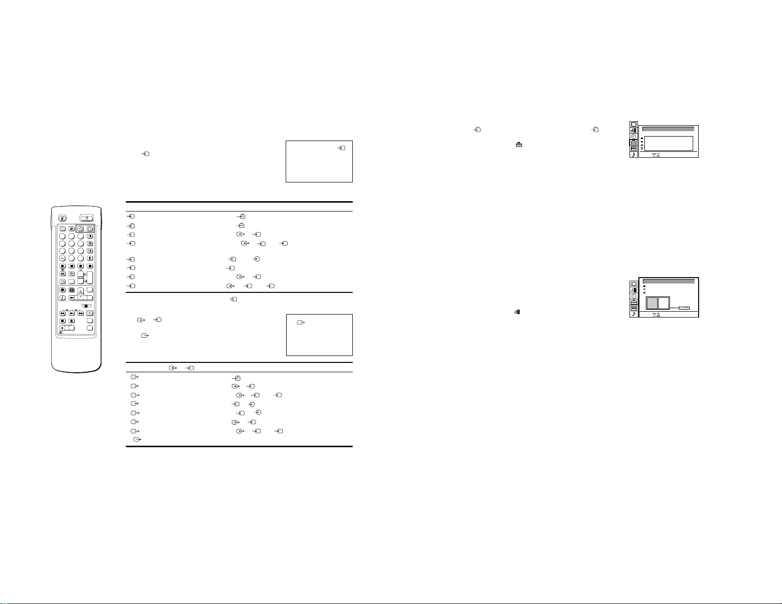
Selecting Input and Output
This section explains how to view the video input picture (of the
video source connected to your TV), and how to select the output
signal using direct access buttons or the menu system.
Selecting input
Press repeatedly to select the input source.
The symbol of the selected input source will appear.
To go back to the normal TV picture
Press O.
Input modes
Symbol
1
2
S
2
3
S
3
4
S
4
You can also select the input mode using the button on the TV.
Selecting the output
The 2 /S 2 connector outputs the source input from the
other connectors.
Press
The symbol of the selected output source appears.
Output modes
Symbol
1
2
S
2
3
S
3
4
S
4
TV
Input signal
Audio/video input through the 1 connector
Audio/RGB input through the
Audio/video input through the
Audio/S video input through the
connector)
Audio/video input through
S video input through the
Audio/video input through the
1 connector
2/ S 2 connector
2/ S 2 or S 2 connector (4-pin
3 and 3 connector on the front
S
3 connector (4-pin connector) at the front
4/ S 4 connector
S video input through the 4 / S 4 or S 4 connector(4-pin connector)
repeatedly to select the output.
2/ S 2 connector outputs
Audio/video signal from the 1 connector
Audio/video signal from the
Audio/S video signal from the
Audio/video signal from the
Audio/S video signal from the
Audio/video signal from the
Audio/S video signal from the
2/ S connector
2/ S 2 or S2 connector (4 pin)
3, 3 connectors
S
3, 3 connectors
4/ S4 connector
4/ S 4 or S4 connector (4 pin)
Audio/video signal from the ) aerial terminal
Using A V Preset
Using this function you can preset the desired input source (e.g.
1, RGB signal) to the respective AV input (AV 1 ). In this
way a connected VTR will automatically switch to the RGB signal.
1
1 Select the symbol
2 Select first “Installation”, then “AV Preset” with >+ or ?– and press
OK.
The AV PRESET menu appears (See Fig. 47).
for “Preset” with >+ or ?– and press OK.
3 Select the desired AV input with >+ or ?– and press OK.
4 Select the desired source with >+ or ?– and press OK.
For the respective AV inputs you have the following possibilities:
AV1 RGB or AV AV3 YC3 or AV
AV2 YC2 or AV AV4 YC4 or AV
5 If you want to name the AV input select “Label” using >+ or ?–
and press OK. Select a letter or a number with >+ or ?– and
press OK. The next element will be highlighted. Select other
characters in the same way. If you want to leave an element blank,
select - and press OK.
After having selected all the characters, press OK repeatedly until
the cursor appears by the next AV input at the left margin.
6 Repeat steps 3 to 6 for the other AV inputs.
Checking and selecting the input and output sources
using the menu
You can display the menu to see which input sources are selected
for the TV screen and PAP screen, and which output source is
selected. You can also select them on the menu display.
1 Select the symbol
1
press OK. The VIDEO CONNECTION menu appears. (See Fig.
48)
You can see which source is selected for the TV and PAP input,
and for the output. If you want to select the input and output on this
menu, go on to the next step.
2 Select TV Screen (input source for the TV screen), PAP (input
source for the PAP screen), or output (output source) with >+ or
?– and press OK. One of the source items changes colour.
3 Select the desired source with >+ or ?–.
For details about each source, see the table on page 24.
4 Press OK.
The selected source is confirmed, and the cursor appears.
for “Video Connection” with >+ or ?– and
5 Repeat steps 2 to 4 to select the source for other inputs or outputs.
AV PRESET
AV-INPUT
AV1
AV2
AV3
AV4
Select and press OK
Fig.47
VIDEO CONNECTION
TV screen [ ]
PAP
Output
TV
Select and press OK
Fig. 48
SOURCE
RGB
Y/C
Y/C
Y/C
VHS 2
LABEL
RGB
YC2
YC2
YC2
TV ----[ ]AV2 VHS 2
[ ]TV -----
TV
24
25

For Your Information
– 15 –
2
1
3
6
45
9
8
7
0
C
PROGR
+
+
1
_
_
1
SAT
+
MENU
_
OK
VTR 1-2-3
MDP
MEM
USE
+
PROGR
RESET
_
RM-838
When recording
when you use the a
(record) button, make
sure to press this button
and the one to the right
of it simultaneously.
Remote Control of Other Sony
Equipment
You can use the TV Remote Commander to control most of Sony
remote-controlled video equipment such as: beta, 8 mm and VHS
VCRs and video disc players.
Tuning the Remote Commander to the equipment
1 Set the VTR 1/2/3 MDP selector according to the equipment you
want to control:
VTR1: Beta VCR
VTR2: 8 mm VCR
VTR3: VHS VCR
MDP: Video disc player
2 Use the buttons indicated in the illustration to operate the
additional equipment.
If your video equipment is furnished with a COMMAND MODE
selector, set this selector to the same position as the VTR 1/2/3
MDP selector on the TV Remote Commander.
If the equipment does not have a certain function, the
corresponding button on the Remote Commander will not operate.
Optimum Viewing Area
For the best picture quality, try to position the projection TV so that you
can view the screen from within the areas shown below.
Vertical viewing area
35˚
35˚
1.5 m and more
Horizontal viewing area
75˚
26
75˚
1.5 m and more
27

– 16 –
Cleaning of the Air Filter
Periodic cleaning of the air filter is necessary. Clean the air
filter once a month. When the filter becomes old and dust
remains on the filter even after cleaning, replace it with a new
one.
• Clean the air filter periodically. If you don’t clean, it may
cause internal heat build-up.
• Never use an air filter which is torn or has holes. Attach the
filter firmly with six tabs. If dust enters the TV, the picture
may become dark.
1 Turn off the power and disconnect the
power cord.
2 Remove the front panel.
Remove the front panel without moving the TV.
Grasping the side of the front panel with your fingers, pull
it forward. Be careful not to catch your fingernails.
3 Pull the filter upward and remove it.
Supplied filter
4 Clean the dust with a vacuum cleaner.
vacuum cleaner
5 Attach the filter.
Attach the six tabs securely.
6 Attach the front panel.
Be careful not to damage the speaker.
Notes
• Attach the filter firmly. If it is not firmly attached, the power will not
turn on.
• Remove the supplied filter in the same way as the attached filter.
• Consult your nearest Sony service center to obtain a new filter.
Replacing the Lamp
When the lamp becomes dark or the picture colour is not
normal, replace with a new lamp.
• Use the lamp XL-100E for replacement. If you use another
lamp, it may cause damage to the TV.
• Do not remove the lamp except when replacing it.
• Before replacing the lamp, turn off the power and disconnect
the power cord.
• Replace the lamp after it becomes cool. The front glass of
the lamp remains 100 °C (212 °F) and more even 30 minutes
after the power is turned off.
• Do not place the removed lamp in proximity to children or
flammable material.
• Do not get the removed lamp wet, or insert objects inside the
lamp. It may cause the lamp to explode.
• Do not place near metal or easily flammable objects, as this
may cause fire. Also, do not put your hand inside the lamp
compartment, as you may be burned.
• Attach the new lamp firmly. If it is not firmly attached, the
picture may become dark.
1
Turn off the power and disconnect the
power cord.
Replace the lamp 30 minutes or more after the power is
turned off.
Prepare the new lamp.
2
Remove the front panel.
Remove the front panel without moving the TV.
Grasping the side of the front panel with your fingers, pull it
forward. Be careful not to catch your fingernails.
3
Loosen the screw with the object such as a
coin and remove the lamp cover.
4
Loosen two screws and pull out the lamp.
The lamp is still too hot just after the power is turned off.
Be careful that you don’t touch the front glass or
surrounding area of the lamp or the glass of the lamp
compartment.
Loosen two screws with the supplied wrench.
Pull out the lamp by the handle.
5
Attach the new lamp.
Fasten two screws tightly.
6
Attach the lamp cover.
Fasten the screws tightly.
7
Attach the front panel.
Be careful not to damage the speaker.
Notes
• Do not touch or stain the front glass of the new lamp or the glass of
the lamp compartment. If the glass become dirty, the picture quality
may deteriorate or the lamp life may shorten.
• Attach the lamp cover firmly. If it is not firmly attached, the power will
not turn on.
• When the lamp burns out, a noise is audible. This does not represent
a damage.
• Consult your nearest Sony service center to obtain a new lamp.
28
29

T roubleshooting
Here are some simple solutions to some problems which may affect the picture and sound.
Problem
No picture (screen is dark), no sound
Poor or no picture (screen is dark), but sound is OK
Poor picture quality when watching an RGB video source
Good picture but no sound
No colour for colour programmes
Remote Commander does not function
If you continue to have problems, have your TV serviced by qualified personnel. Never open the casing yourself.
Solution
• Plug in the TV in.
• Press f on the TV (if f indicator is on, press O or a programme number
on the Remote Commander).
• Check the aerial connection.
• Check if the selected video source is on.
to enter the PICTURE CONTROL menu and adjust the
• Press
brightness, contrast and colour.
repeatedly to select .
• Press
+.
• Press
• If o is displayed on the screen, press o.
to enter the PICTURE CONTROL menu, select RESET, then
• Press
press OK.
• The batteries are weak.
Warning Indicators
When a problem occurs, the indicator flashes as follows.
Attempt the solution recommended for the given problem.
When a problem occurs while operating the set, the f
(standby) indicator flashes first and then warning will be
indicated.
AB
– 17 –
Cause
The lamp burns out or the
quality of the lamp is deficient.
The cover of the filter or the
lamp is removed.
The fan for cooling stops.
Internal heat builds up.
If the lamp flashes in a way not described above, consult your nearest Sony service center.
Indicator flashing patterns
The B indicator flashes twice then A flashes once.
Flashing continues in this manner.
The B indicator flashes three times then A flashes once.
Flashing continues in this manner.
The B indicator flashes four times then A flashes once.
Flashing continues in this manner.
The B indicator flashes five times then A flashes once.
Flashing continues in this manner.
Stabilizing the Projection TV
After setting up, secure the projection TV to a wall, etc., with the supplied brackets, for safety
purposes.
1 Mount the two supplied brackets with the screws to the upper rear side
of the projection TV.
Bracket (supplied)
2 Pass a strong cord or a chain through each bracket mounted in 1, and
then secure to a wall or a pillar, etc.
30
31
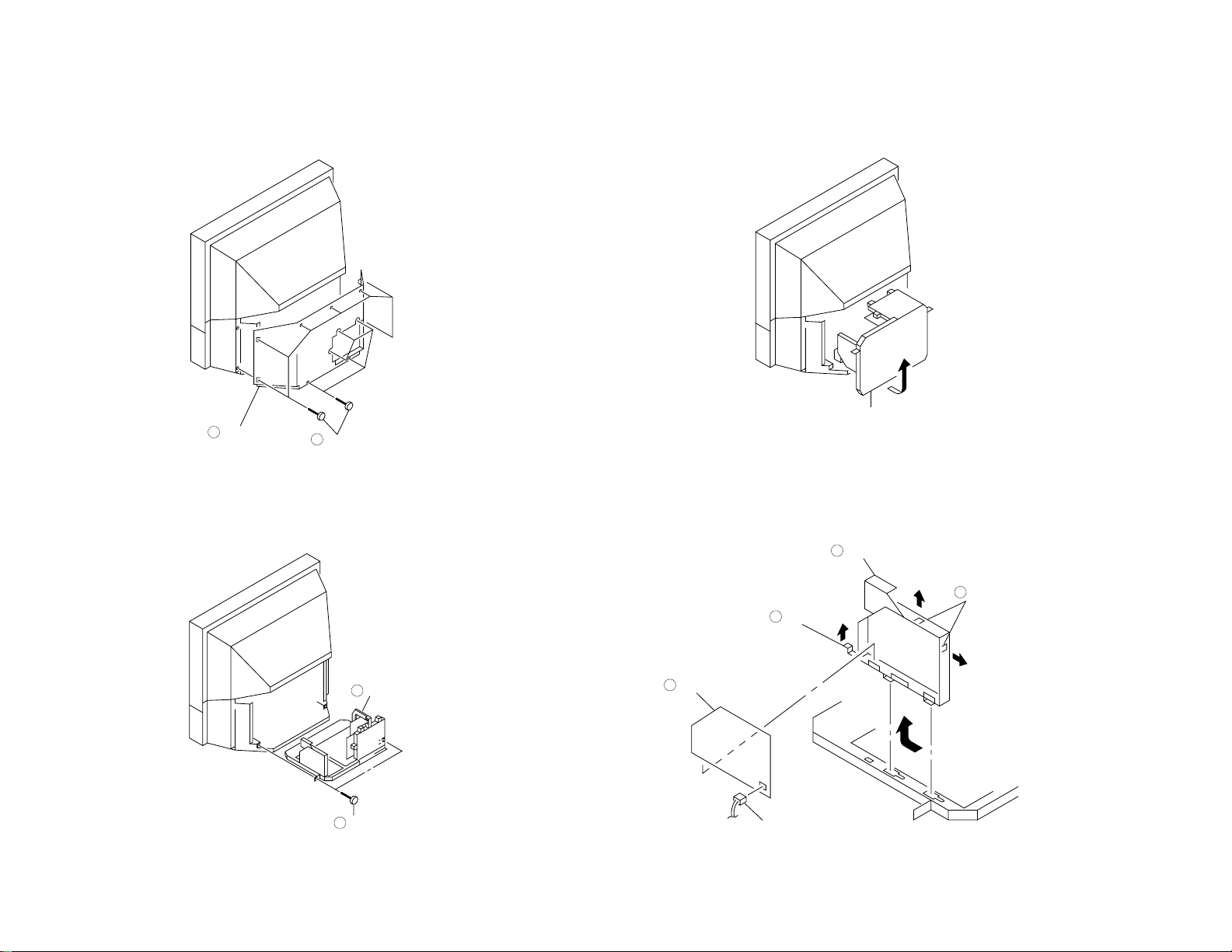
SECTION 2
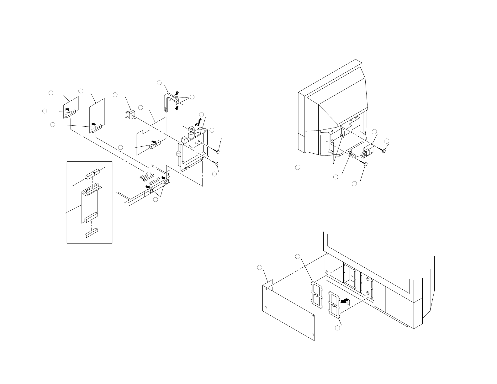
Rear cover
2
Twelve screws
(+BVTP 4 x 16)
1
Chassis assy
2
Two screws
(+BVTP 4 x 16)
1
Chassis assy
CN6504
F2 board
2
Claw
3
F2 bracket
4
Two claws
1
DISASSEMBLY
– 18 –
2-1. REAR COVER REMOVAL
2-2. CHASSIS ASSY REMOVAL
2-3. SERVICE POSITION
2-4. F2 BOARD AND F2 BRACKET REMOVAL
– 19 –
Two claws
1
Holder
2
Claw
3
BB board
4
Claw
5
B1 board
6
Screw
(+B M3 x 8)
7
RF booster
8
Three screws
(+BVTP 4 x 16)
9
Two claws
10
Terminal board
11
Claw
12
J board
13
Extension board
1-589-554-11
Common use
(BB, B1 and
J Boards)
Two printed circuit
board holders
4
Terminal
2
Two screws
(+BVTP 3 x 12)
1
Power block
5
Two screws
(+BVTP 4 x 16)
3
Filter
2
Front panel (L)
1
Filter
(Reserve)
3
2-5. BB, B1 AND J BOARDS REMOVAL
(EXTENSION BOARD)
2-6. POWER BLOCK REMOVAL
2-7. FILTER REMOVAL

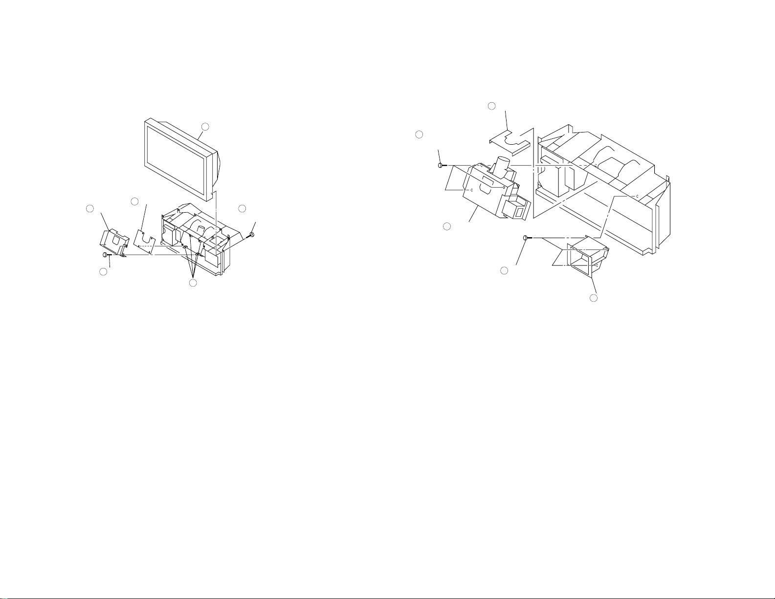
– 20 –
Lamp door
3
Screw
(Ornamental
screw B)
2
Front panel (R)
1
Lamp
5
Two screws
(Hexagon socket bolt 4 x 12)
4
Two screws
(+BVTP 3 x 12)
5
F1 board
6
Eight screws
(+BVTP 4 x 16)
1
Front cover
2
H board
4
Six screws
(+BVTP 3 x 12)
3
Two screws
(+BVTP 4 x 16)
1
Screen frame
3
Eight screws
(+BVTP 4 x 16)
2
2-8. LAMP REMOVAL
2-9. H AND F1 BOARDS REMOVAL
2-10. SCREEN FRAME REMOVAL
– 21 –
Screen mirror
block
2
Six screws
(+BVTP 4 x 16)
1
Four printed circuit
board holders
5
Four screws
(+BVTP 3 x 12)
3
Shield
4
C board
6
Optical shield
1
Three screws
(+BVTP 4 x 16)
4
Optical unit
5
Three screws
(+BVTP 4 x 16)
2
Lamp base
3
2-11.C BOARD REMOVAL
2-12. OPTICAL UNIT REMOVAL
KL-37W2/37W2K RM-838
KL-50W2/50W2K/50W2U RM-838
SECTION 3
CIRCUIT ADJUSTMENTS
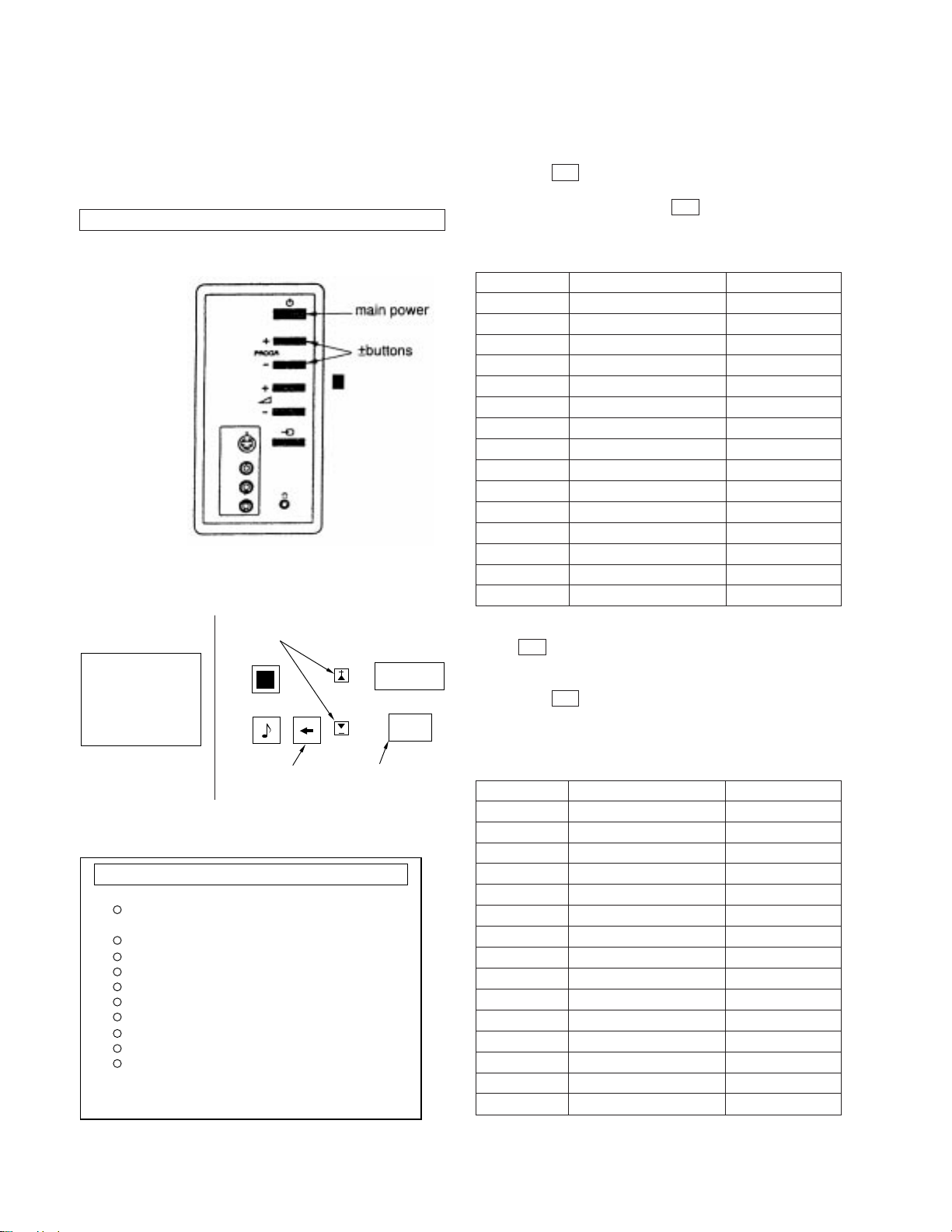
3-1. ELECTRICAL ADJUSTMENTS
Service adjustment to this model can be performed with the supplied remote commander, RM-838.
HOT TO ENTER INTO SERVICE MODE
1. Turn on the main power switch of the set while pressing the +
(plus) and – (minus) buttons on the customer front panel.
Fig. 4-1
2. “TT” will appear on the upper right corner of the screen.
Command operation in service mode
Item selection, data up/down
TT
MENU
OK
4. Press the 4 and % buttons on the remote commander to select
+
the adjustment item.
5. Press the OK button to procced to the next menu.
6. If the adjustment item is Video cont press the % button to
move to Video cont then press OK button.
7. The Menu as indicated in Fig will appear on the screen.
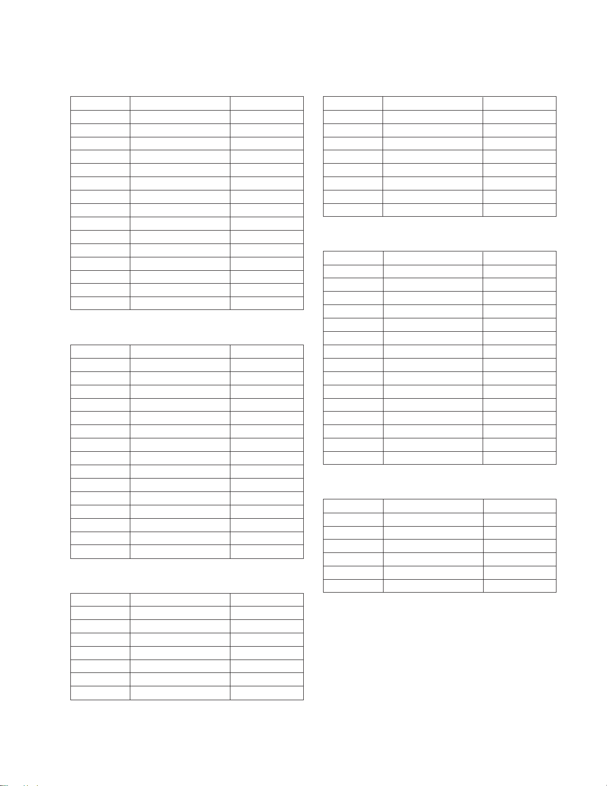
Video Cont. CXA1839
Item No. Adjustment item Data Amount
1 Sub BRT [6]
2 Sub COL1 [15]
3 Sub CON1 [15]
4 PIC [53]
5 HUE [31]
6 COL [31]
7 BRT [31]
8 SHP [31]
9 Sub HUE [6]
10 D COL [off]
11 SHP Lim [off]
12 Age WHT [off]
13 R-Y R [8]
14 R-Y B [13]
15 G-Y R [11]
8. Press the % button to move > to the adjustment item and press
the OK button.
9. Press the 4 and % buttons to change the data in order to com-
+
ply with each standard.
10. Press the OK button to write data into memory.
11. Turn off the power to quit the service mode when adjustments
have been completed.
BACK menu
Fig. 4-2
Selection completion,
data writen-in
Fig. 4-3
3. Press 01 on the commander to get the menu on screen.
Venus V2.07 AE-3 12/03/96
Init
Video Contr
Scan Con.
Video Proc M
Timing Gen.
RGB Interface
PAP
SRC
TDA6812
PALPLUS
CXA1839
CXD2428
CXD2030
CXD2412
CXA2011
CXD2031
CXD2032
TDA6812
Scan Converter CXD2428
Item No. Adjustment item Data Amount
1 H-shift [126]
2 V-shift [14]
3 H-phase [58]
4 V-phase [31]
5 H-SZ-RD (40h) [140]
6 H-SZ-RD (50h) [3]
7 H-SZ-WR (41h) [140]
8 H-SZ-WR (51h) [3]
9 LN-DAT0 [0]
10 MD-DAT0 [3]
11 LN-DAT1 [0]
12 MD-DAT1 [0]
13 LN-DAT2 [0]
14 MD-DAT2 [0]
15 LN-DAT3 [0]
– 22 –
KL-37W2/37W2K RM-838
KL-50W2/50W2K/50W2U RM-838
Video Proc M CXD2030
Item No. Adjustment item Data Amount
1 DNR [on]
2 DNR value [5]
3 TA Sync C1p pls width [16]
4 TB BGP position [50]
5 TD CLP position [25]
6 Foto CD SW [off]
7 BLK porch pos [16]
8 NTSC TD BGP pos [25]
9 PAL TD BGP pos [25]
10 Not Secam TB BGP pos [50]
11 Secam TB BGP pos [50]
12 358 NR Level [3]
13 443 NR Level [5]
14 Color detect Mode [0]
15 Extern Y/C [off]
RGB Interface CXA2011Q
Item No. Adjustment item Data Amount
1 Drive Level [48]
2 Sig Sel [0]
3 Sub Bright [23]
4 Sync Sel [0]
5 Sync SW [3]
6 ABL SW [off]
7 AKB-T [off]
8 HD Sync [on]
9 R Drive [31]
10 G Drive [31]
11 B Drive [31]
12 R Cutoff [124]
13 G Cutoff [124]
14 B Cutoff [123]
15 Gamma Level [0]
TIMING GENERATOR CXD2412QA
Item No. Adjustment item Data Amount
1 SLSH1 [on]
2 SLSH2 [off]
3 SLSH3 [on]
4 BH Bias [252]
5 RH Bias [252]
6 BL Bias [112]
7 RL Bias [122]
PAP CXD2031
Item No. Adjustment item Data Amount
1 Main phase WR start [52]
2 Sub phase WR start [20]
3 Main RD start [43]
4 Brightness sub [8]
5 Twin pic [on]
6 WR inhibit1 [off]
7 WR inhibit0 [off]
8 RD inhibit0 [off]
SRC CXD2032
Item No. Adjustment item Data Amount
1 YCD [0]
2 YDF [0]
3 COF [0]
4 Reference clamp [0]
5 Offset [off]
6 IIR latch [off]
7 BGP Sync SW [0]
8 Clamp [off]
9 50/60 [off]
10 Reference clamp [32]
11 Offset Level [0]
12 System Delay [9]
13 Offset Level [0]
14 FVSW [on]
15 Mask SW [on]
TDA 6812
Item No. Adjustment item Data Amount
1 Stereo-sep [15]
2 Pre-Volume [2]
3 Treble-offset L/R [0]
4 Bass-offset L/R [0]
5 Treble-offset C/S [255]
6 Bass-offset C/S
– 23 –
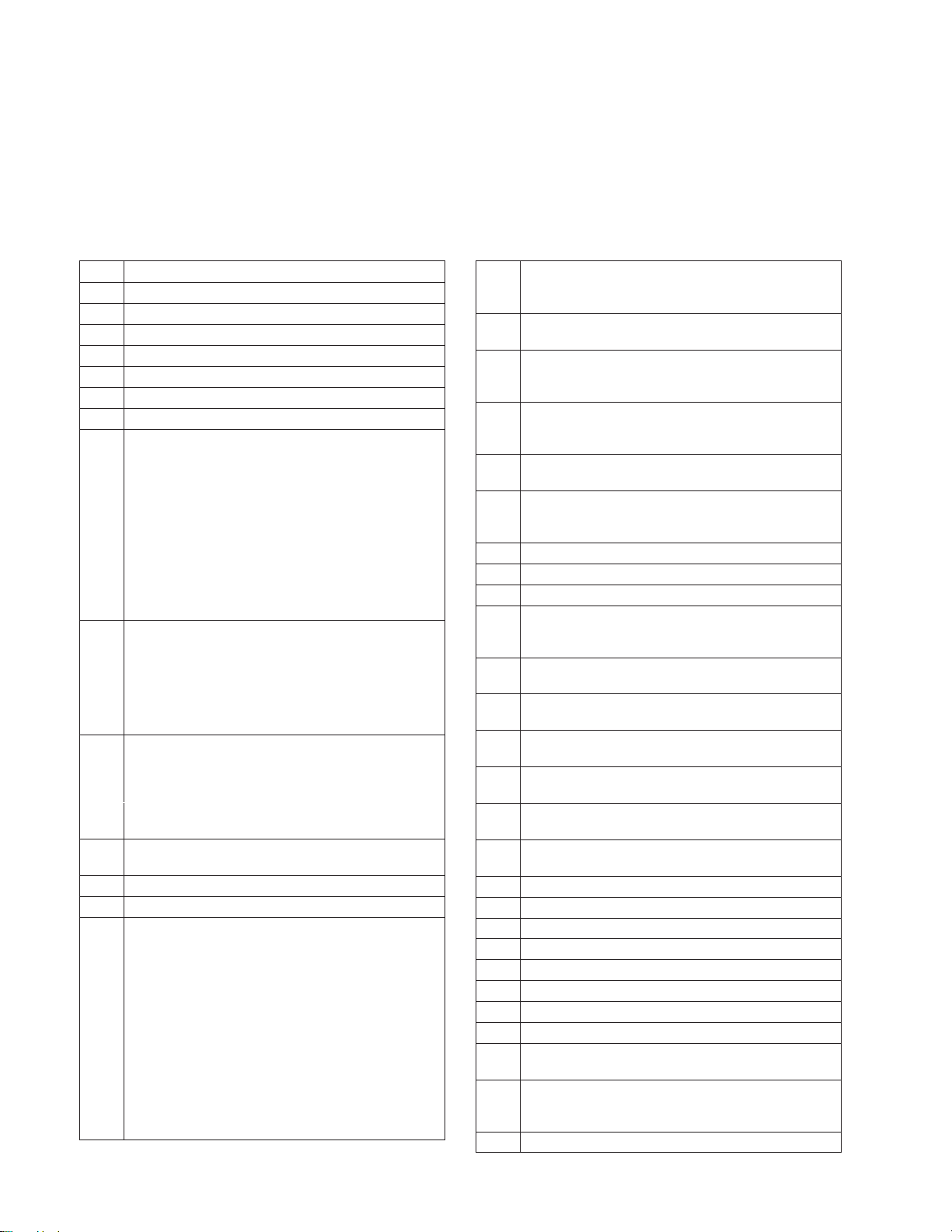
KL-37W2/37W2K RM-838
KL-50W2/50W2K/50W2U RM-838
3-2. TEST MODE
Is available by pressing the Test button twice, OSD “TT” appears. The functions described below are available by pressing the two
numbers. To release Test Mode 2, press 0, 10, 20...twice or switch the TV into Standby Mode. Pressing the two Local Control buttons (+
and –) during Power ON will also switch into “TT” mode.
In TT mode, it is possible to remove the Menu from the screen by pressing the Speaker Off button once. Pressing the Speaker OFF button
a second time will cause the menu to reappear. The Function is kept even when the menu is not displayed!!
00 Switch back to normal mode - TT mode off
01 Switch service menu on
02 no function
03 Set Volume to 30 %
04 Service Menu in “Service Mode”
05 Service Menu in “Production Mode”
06 Set Volume to 80 %
07 Aging mode
08 Shipping condition (Production request)
To ensure that all TV sets leave the Production with
the same pressettings. Programme 1 is selected, AV
IN is set to AV1, AV Out is set to TV Out, Volume and
HP Volume is set to 35 %, Resolution is set to high,
Format is set to 4:3, Pip is set to Top Left position,
Pip is switched off, TT mode is switched off, all
analogue values are set to the reset setting, space
Sound - Equalizer - Loudness = off, DNR off, Dig.
Mode = 1, Wide Zoom Mode for W28 models, Menu
Language Reset, Prog. Pointer table reset Non
Interlace is allowed in Text mode.
09 Language reset. With this function the Menu
Language is set to “unselected” (NVM Bank OAAH
Adress ODCH). The value for the Language Group is
not overwritten (Selection West/East/Common).
The Language Menu appears now automatically
when the TV set is switched ON as long as no new
language is selected.
10 The TT number will be deleted.
All numbers with 0 (10, 20 30, 40, 50, 60, 70, 80, 90)
will reset the TT number. A new number can be
selected. TT display is kept
11 Direct access to Balance. With Cursor Up/Down the
Balance can be controlled (w/o OSD, Menu display)
12 Direct access to Hue. With Cursor Up/Down the Hue
can be controlled (w/o OSD, Menu display)
13 Display of Software Version and TV set configuration
14 Production Info Display
15 Read factory setting from ROM (Program code) and
store this data at Last Power Memory data location
(The previous last power memory data is overwritten)
AE3 has 3 packages of Analogue data:
1. Last Power memory data. This data is sent
continiously to the corresponding IC’s (TDA1839, SC,
TDA6812) with this data the TV picture/sound
appears.
2. Reset data. By pressing “Reset” in the menu this
data is transfered from Reset Data location to the
Last Power data location in the NVM.
That means the previous Last Power Memory Data is
overwritten by the Reset data last Power memory and
Reset data are now the same.
15 3. Factory fixed data. In the ROM code of the micro
processor are also analogue datas which are fixed
(ROM can’t be changed)
16 Save actual Last Power Memory data at Reset Data
location (The previous Reset data is overwritten)
15/16 With these two functions, it is possible to preset user
defined Reset values (just TT16) or to preset factory
defined Reset values (first TT15 then TT16)
17 This functions presets the Labels for the AV sources:
The Labels are AV1, RGB, AV2, YC2, AV3, YC3,
AV4, YC4.
18 Text possible On/Off selection of Text (toggle
function)
19 Direct access to Stereo Separation
With cursor Up/Down the Stereo separation can be
adjusted (w/o OSD, Menu display)
20 see TT10
21 no function
22 Operating Timer and Error Monitor display
23 Direct access to Sub Brightness Adjustment
With cursor Up/Down the Sub BRT can be adjusted
(w/o OSD, Menu display)
24 Direct access to Sub Color. With Cursor Up/Down the
Sub Color can be adjusted.
25 Status menu display (SubController, CXA1840
Status, Main Controller.)
26 Text Character set selection (Char set 06 -> West
Europe)
27 Text Character set selection (Char set 38 -> East
Europe)
28 Text Character set selection (Char set 40 -> West
Europe) US English
29 Text Character set selection (Char set 55 -> West
Europe) Turkish
30 see TT10
31 Increase V-Aperture
32 Decrease V-Aperture
33 no function
34 no function
35 no function
36 Mtx Register 112 = intern display clock
37 Mtx Register 112 = extern display clock
38 Automatic selection of Screen Modes: 4:3 -> Zoom ->
Zoom up -> Zoom down -> smart -> wide.
39 Reset Programme Table (NVM Bank 0ACH) The
sorting of programmes in “Programme Sorting Menu”
is reset.
40 see TT10
– 24 –
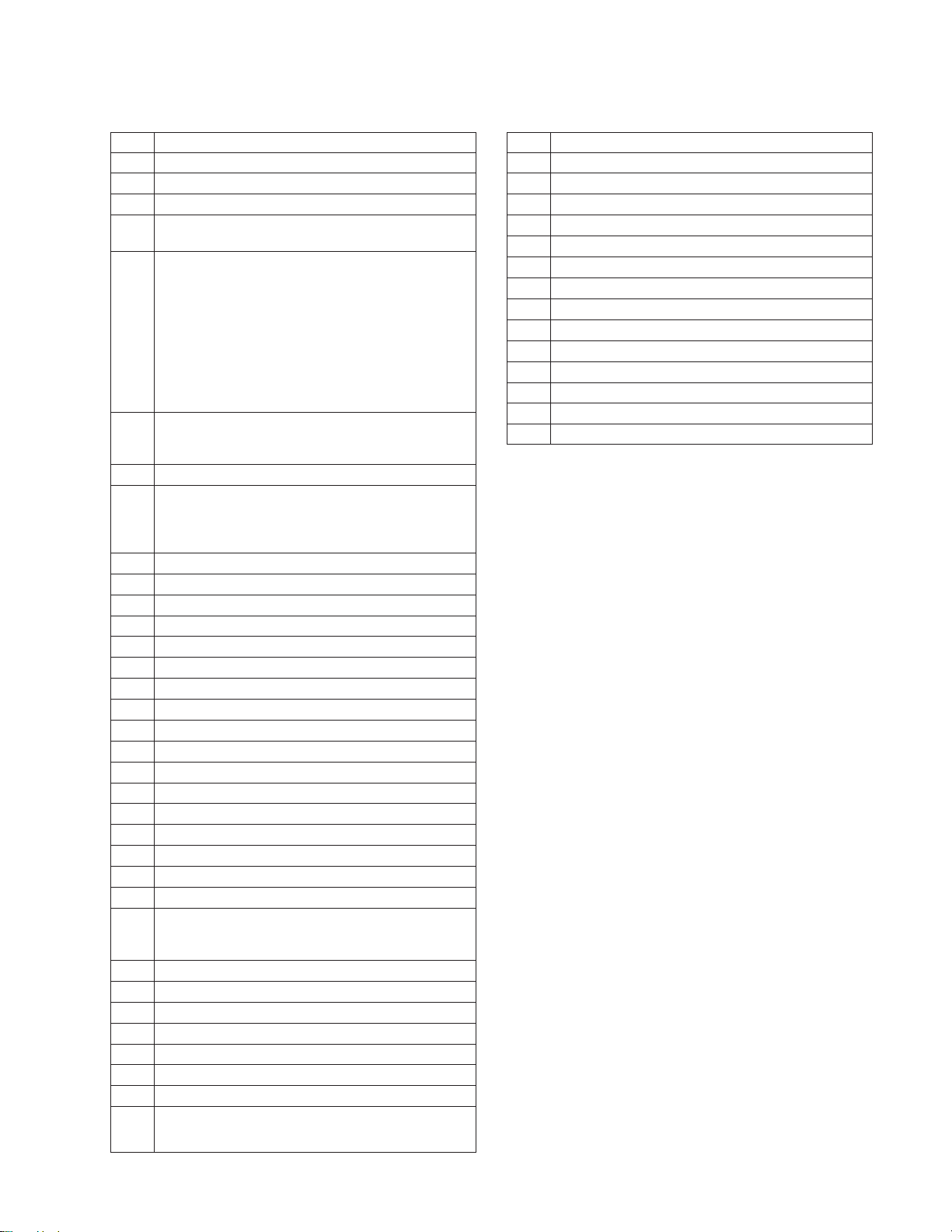
KL-37W2/37W2K RM-838
KL-50W2/50W2K/50W2U RM-838
41 Picture min
42 no function
43 no function
44 no function
45 Set NVM to Protect mode (Bank 0AEH Adr. 0FFH
write with 0)
46 IR Channel Pressetting Mode. The channel pressetting
can be done by a Special IR transmitter (Deatiled INFO
about IR transmitter from SEC)
Sequence: TT46 -> --PR Number select display
appears Select Prog. No from where
the channel shall be stored.
--> Now TV is waiting for IR sequence <--
--> If no IR transmission starts TT46 is
released after 20 secs <-- !Note: When TT46 is active,
any transmission will be interpreted as PROG data !
47 Direct access to Headphone Source Selection with
Cursor Up/Down the Source of Headphone can be
selected (w/o OSD, Menu display)
48 no function
49 The EEPROM Testbyte is erased. After Power OFF
-> ON the complete EEPROM data (exept channel
tables) are overwritten. EEPROM Protection byte is
set to 0 protection mode
50 see TT10
51 Strobo mode is activated.
52 no function
53 no function
54 no function
55 MTX Slicer Control “Low Pass” (only Sys L))
56 MTX Slicer Control “No Compensation”
57 Megatext Service Menu ON
58 MTX Small Framing Code Window
59 MTX Wide Framing Code Window
60 see TT10
61 no function
62 ACI disable.
63 ACI enable.
64 Reset all IIC Slave commands
65 Reset stored error codes in NVM.
66 Reset for Sub Controller.
67 Direct access to Headphone Volume. With cursor Up/
Down the Headphone volume can be controlled (w/o
OSD, menu display)
68 ignore errors.
69 reset ignore errors (show errors)
70 see TT10
71 Picture Rotation Function On/Off toggle.
72 no function
73 Megatext RGB textlevel one step decreased
74 Megatext RGB textlevel one step decreased
75 reserved for TT command Network ID, not
inplemented yet
76 CXD2030 Default data setting.
77 CXD 2031 Default data setting.
78 CXD 2032 Default data setting.
79 CXD 2428 Default data setting.
80 see TT10
81 Default data setting CXA2011
82 no function
83 no function
84 CXA 1839 Default data setting
85 Default data setting CXD 2412
86 no function
87 Default data setting CXD 2030
88 Text character set Russian/East
89 Text character set Russian/West
90 see TT10
– 25 –

KL-37W2/37W2K RM-838
KL-50W2/50W2K/50W2U RM-838
3-3. ERROR MONITOR AND DETECTION
In the menu ‘Error Monitor’, information about the error status of
the set is displayed.
• Actual operating time
• Last five errors which are stored in the NVM
• Actual error
Erroe Monitor
Operating Time
000355 h 35min
Saved Errors
1. 40h=D1 Board
2. 60h=Q Board
3. 70h=T Board
4. 00h=no error occured
5. 00h=no error occured
Actual Error
-> 00h=no error occured
to reset the NVM press ‘TT’ 65
Additionally the Error Reader can be connected to the service connector to read out the actual errors.
The device check itself is active while the TV set is running out of
stand-by mode. The devices are checked by sending an I2C start
sequence and if there is no acknowledgement back from the devices it is regarded as an error. Each device is checked three times
and if at every attempt there is no reply from the relevant device an
error is given. To read the error codes press ‘TT’ followed by 22
on the commander to view the Error Monitor menu.
To reset the error codes in the NVM press ‘TT’ followed by 65 on
the remote commander.
TABLE OF ERROR CODES
Error
Code
000h
001h
002h
003h
010h
020h
030h
040h
050h
060h
070h
011h
012h
Device
no device
IIC 1 and IIC 2
IIC 1
IIC 2
A Board
A1 Board
BX-Board
(B, B1, B2)
D1 Board
J Board
Q Board
T Board
CXP85332
ST24C16
Description
no error has occured
IIC 1 and IIC 2 blockaded
IIC 1 is blockaded
IIC 2 is blockaded
A Board is defective
A1 Board is defective
B, B1, or B2 Board is
defective
D1 Board defect
J Board defect
Q Board defect
T Board defect
No response from the
Subcontroller
No response from the NVM
Board
–
–
–
–
–
–
–
–
–
–
–
A
A
Error
Code
013h
014h
015h
016h
017h
018h
019h
021h
022h
031h
032h
033h
034h
035h
036h
037h
041h
051h
061h
071h
072h
Device
SDA5273
TDA6812
SAA7283
UV916H
CXA1839Q
CXA1840
RGB8443
TDA6622
TDA7317
CXD2030R
CXD2031R
CXD2032R
CXD2033R
CXD2035R
TDA9160
TDA9145
CXA1526
CXA1855
83C65202
UV1316/
TSA5526
CXA1875
Description
No response from the
Megatext IC
No response from the
Sound Processor
No response from the
Nicam Decoder
No response from the Main
Tuner
No response from the Video
Controller
No response from the CRT
Driver
No response from RGB/
YUV
Audio processor of the
Center and Surround
channel in the case of
Dolby Prologic does not
respond.
No reponse from the
Equalizer.
No response from the
Digital Video
Processor.
No response from the Twin
Picture IC.
No response from the
Digital Sampling Rate
Converter.
No response from the
Picture in Picture IC.
No response from the
Aspect Converter.
No response from the
Chroma Decoder.
No response from the
Chroma Decoder (on
French models only.)
No response from the
Convergence IC.
No response from the AVSwitch
No response from the Local
Controller.
No response from the
Subtuner.
No response from the Port
Expander.
Board
A
A
A
A
A
A
A
A1
A1
B/B1
B1
B/B1
B
B/B1
B/B1
B2
D1
J
Q
T
T
– 26 –

KL-37W2/37W2K RM-838
KL-50W2/50W2K/50W2U RM-838
3-4. REGISTRATION ADJUSTMENT
Preparation
• Aspect ratio...................................... 16:9
• Image quality adjusting menu.......... Standard
Note: In adjusting the registration, the registration fixing block is
secured with an adhesive, and therefore the PANEL
BLOCK ASSY is required.
• Tools and Kit
Hex. wrench keys (2 mm, 1.5 mm)
PANEL BLOCK ASSY (Refer to SECTION 5. EXPLODED VIEWS)
1. Entering G monochrome crosshatch signal or B monochrome
crosshatch signal, adjust the registration between B and G.
Overlay B image on the G image as shown, while turning the
registration adjusting screws in the order of θ → X → Y.
2. Enter full black signal to the B panel, then the R monochrome
crosshatch signal to adjust the registration of R and G.
3. Tighten tentatively the registration fixing screws on the R and
B panels, and secure the registration blocks A and B with an
adhesive.
4. Tighten the registration fixing screws.
Registration block A
X adjusting
screw
Fixing screw
(2mm)
Y adjusting screw
θ adjusting
screw
Registration
block B
B
G
X
B
Y
G
LENS FOCUS ADJUSTMENT
1. Loose screw of LENS focus.
2. Adjust LENZ focus so that best focus.
G
B
q
Adjust the lower right as rotational reference
q adjustment
X adjustment (horizontal)
No
Y adjustment (vertical)
within specification?
Yes
Fix the registration
3-5. C BOARD ADJUSTMENT
1. PLL f0 Adjustment
(1) WIDE Mode
1) Change to “WIDE Mode”.
2) Input to monoscope signal.
3) Change “H. SYNC input” CN5202 1pin input to open (no
signal).
4) Connect 100 Ω resister between 2pin of IC5004 and
TP5009, then connect frequency counter to 1pin of
IC5004.
5) Turn L5002 and adjust to 13.67 ± 0.1 MHz.
6) Input H. SYNC for PAL double speed.
7) Confirm that the waveform for TP5007 <RPD2> shall be
Fig.
13.67 ± 0.1 MHz
2.3 ± 0.3 V
31.78 µs
(2) 4.3 Mode
1) Change to “4 : 3 Mode”.
2) Input to monoscope signal.
3) Change H. SYNC CN5202 1pin input to open (no signal).
4) Connect 100 Ω resister between 2pin of IC5004 and
TP5009, then connect frequency counter to 1pin of
IC5004.
5) Turn L5004 and Adjust to 10.22 ± 0.05 MHz.
6) Input H. SYNC for PAL double speed.
7) Confirm that the waveform of TP5004 <RPD1> shall be
Fig.
10.22 ± 0.05 MHz
2.5 ± 0.3 V
2. r curve adjustment
(1) Change to “WIDE Mode”.
(2) Input PAL double speed signal 10 step.
2.0 ± 0.02 Vp-p
– 27 –
2.7 ± 0.02 V
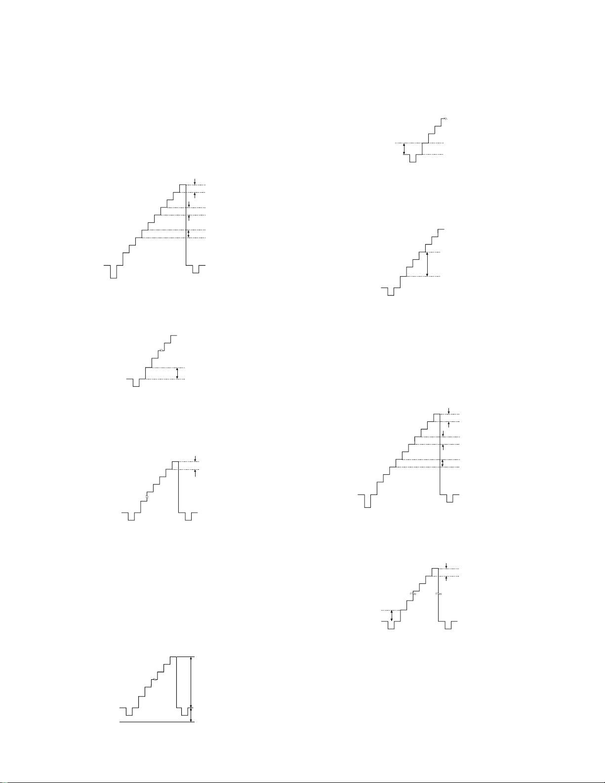
KL-37W2/37W2K RM-838
KL-50W2/50W2K/50W2U RM-838
(3) R ch
1) Connect Oscilloscope to TP5201 <R>.
2) Add 2.25 ± 0.02 V to TP5211 <RLBS>
3.95 ± 0.02 V to TP5210 <RHBS>
by DC power supply.
3) Confirm that the signal level under 10 IRE and above 80
IRE is increased with above condition.
60 mV
40 mV
60 mV
4) Adjust RV5201 <RL, GAIN> so that signal level of
“0 IRE ~ 10 IRE” might be 130 ± 10 mV.
10 IRE
0 IRE
R ch 130 mV
4) Turn RV5401 <GL, GAIN> to the right direction and ad-
just so that “0 IRE ~ 10 IRE” might be 180 ± 10 mV.
180 mV
10 IRE
0 IRE
5) Change TP5411 <GLBS>, TP5410 <GHBS> to OPEN.
6) Turn RV5402 <GL, BIAS> to the left direction and adjust
so that “10 IRE ~ 40 IRE” might be 380 ± 10 mV.
40 IRE
G ch 380 mV
10 IRE
(5) B ch
1) Connect Oscilloscope to TP5601 <B>
2) Add 2.20 ± 0.02 V to TP5611 <BLBS>
3.95 ± 0.02 V to TP5610 <BHBS>
by DC power supply.
3) Confirm that the signal level under 10 IRE and above 80
IRE is increased with above condition
5) Turn RV5209 <RH GAIN> to the left direction by aplox
150° and adjust so that “90 IRE ~ 100 IRE” might be minimum.
minimum
(In Case that “100 IRE ~ GND” is above 3.7 V ; Adjustment is N.G)
(4) G ch
1) Connect Oscilloscope to TP5401 <G>.
2) Add 2.25 ± 0.02 V to TP5411 <GLBS>
3.95 ± 0.02 V to TP5410 <GHBS>
by DC power supply.
3) Confirm that the signal level under 10 IRE and above 90
IRE is increased with above condition.
2.0 ± 0.02 Vp-p
60 mV
40 mV
60 mV
4) Turn RV5601 <BL, GAIN> to the right direction and ad-
just so that “0 IRE ~ 10 IRE”might be “160 ± 10 mV”
65 mV
90 IRE
10 IRE
B ch 160 mV
2.7 ± 0.02 V
– 28 –
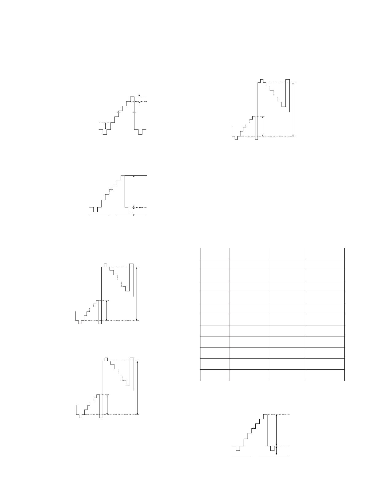
KL-37W2/37W2K RM-838
KL-50W2/50W2K/50W2U RM-838
5) Turn RV5609 <BH, GAIN> and adjust so that “90 IRE ~
100 IRE” might be “65 ± 10 mV”
(RV5609 can be adjusted at mechanical center of the VR
to obtain above metioned condition. In case that “100 IRE
~ GND” is above 3.7 V Adjustment is N.G)
65 mV
90 IRE
10 IRE
B ch 160 mV
(6) IC level adjustment (R ch)
1) Change to “WIDE Mode”.
2) Input PAL double speed signal 10 step waveforms.
2.0 ± 0.02 Vp-p
2.7 ± 0.02 V
GND
3) Add 0 V to TP5211 <RLBS> and 9 V to TP5210 <RHBS>
by DC power supply.
4) Adjust the level by RV5205 <R-GAIN> as “0 IRE ~ 100
IRE” on TP5203 <R-sig2> is 1.50 ± 0.02 Vp-p.
7) By RV5204 <R-S, GAIN2> & RV5208 <R-S, BIAS2>,
adjust the waveform for TP5204 <R-sig3> to the waveform for TP5203 <R-sig2>. (within ± 0.02 V)
R ch
6.2 ± 0.02 Vp-p
G ch
9.6 ± 0.02 Vp-p
B ch
R ch 1.50 ± 0.02 Vp-p
G ch 3.10 ± 0.02 Vp-p
B ch 1.50 ± 0.02 Vp-p
6.7 ± 0.02 Vp-p
8) Confirm that the waveform for TP5203 <R-sig2> is
within standard mentioned.
(7) IC Level Adjustment (G ch)
1) Proceed 4) ~ 8) by the same way as R ch.
2) Proceedure 3) to add external voltage must not be done.
As for “related VR” and “output terminal” please refer to
the Fig.
(8) IC Level Adjustment (B ch)
1) Proceed 3) ~ 8) by the same way as R ch.
As for “related VR” and “output terminal” please refer to
the Fig.
R ch
G ch
B ch
R ch
6.2 ± 0.02 Vp-p
G ch
9.6 ± 0.02 Vp-p
B ch
R ch 1.50 ± 0.02 Vp-p
G ch 3.10 ± 0.02 Vp-p
B ch 1.50 ± 0.02 Vp-p
6.7 ± 0.02 Vp-p
5) Adjust by RV5206 <R-BIAS> so that “Positive polarity 0
IRE ~ Negative polarity 0 IRE” might be 6.2 ± 0.02 Vp-p.
R ch
6.2 ± 0.02 Vp-p
G ch
9.6 ± 0.02 Vp-p
B ch
R ch 1.50 ± 0.02 Vp-p
G ch 3.10 ± 0.02 Vp-p
B ch 1.50 ± 0.02 Vp-p
6.7 ± 0.02 Vp-p
6) By RV5203 <R-S, GAIN1>, RV5207 <R-S, BIAS1>, adjust the waveform for TP5202 <R-sig1> to the waveform
TP5203 <R-sig2>. (within ± 0.02 V)
-Sig 1
-Sig 2
-Sig 3
LBS
HBS
-GAIN
-BIAS
-S.GAIN 1
-S.BIAS 1
-S.GAIN 2
-S.BIAS 2
TP5202
TP5203
TP5204
TP5211
TP5210
RV5205
RV5206
RV5203
RV5207
RV5204
RV5208
TP5402
TP5403
TP5404
TP5411
TP5410
RV5405
RV5406
RV5403
RV5407
RV5404
RV5408
(9) V com Adjustment
1) Change to “WIDE Mode”.
2) Input PAL double speed signal 10 steps waveform.
2.0 ± 0.02 Vp-p
GND
2.7 ± 0.02 V
TP5602
TP5603
TP5604
TP5611
TP5610
RV5605
RV5606
RV5603
RV5607
RV5604
RV5608
– 29 –
 Loading...