

Sony KDL-32R505C, KDL-40R557C, KDL-40R550C, KDL-40R555C, KDL-48R510C Service Manual
...
SERVICE MANUAL
Version Date Subject
1.0 02/2015 Original manual issue.
LCD TV
9-888-173-A1
HISTORY INFORMATION FOR THE FOLLOWING MANUAL:
ORIGINAL MANUAL ISSUE DATE: 02/2015
GN1S CHASSIS
Segment: SE2N
SERVICE MANUAL
LCD TV
GN1S CHASSIS
Segment: SE2N
9-888-173-A1

KDL-32R500C, 505C, 507C, 40/48R510C, 550C, 555C, 557C
3
MODEL LIST
MODEL COLOR COMMANDER DEST.
KDL-32R500C Black RMT-TX102U (UC2)
US/CND
KDL-32R505C Black RMT-TX102B (CR1)
COSTA RICA
(ECU)
ECUADOR
(LA8)
CHILE
PERU
VENEZUELA
KDL-32R507C Black RMT-TX102B (CO1)
COLOMBIA
KDL-40R510C Black RMT-TX102U (U2)
US
KDL-40R550C Black RMT-TX102U (LA1)
MX
(UC2)
US/CND
KDL-40R555C Black RMT-TX102B (CR1)
COSTA RICA
(ECU)
ECUADOR
(LA8)
CHILE
PERU
VENEZUELA
MODEL COLOR COMMANDER DEST.
KDL-40R557C Black RMT-TX102B (CO1)
COLOMBIA
KDL-48R510C Black RMT-TX102U (U2)
US
KDL-48R550C Black RMT-TX102U (LA1)
MX
(UC2)
US/CND
KDL-48R555C Black RMT-TX102B (BR6)
BRAZIL
(CR1)
COSTA RICA
(ECU)
ECUADOR
(LA8)
CHILE
PERU
VENEZUELA
KDL-48R557C Black RMT-TX102B (CO1)
COLOMBIA

CAUTION
These servicing instructions are for use by qualified service personnel only.
To reduce the risk of electric shock, do not perform any servicing other than that contained in the operating instructions unless you are qualified to do so.
WARNING!!
An isolation transformer should be used during any service to avoid possible shock hazard, because of live chassis.
The chassis of this receiver is directly connected to the ac power line.
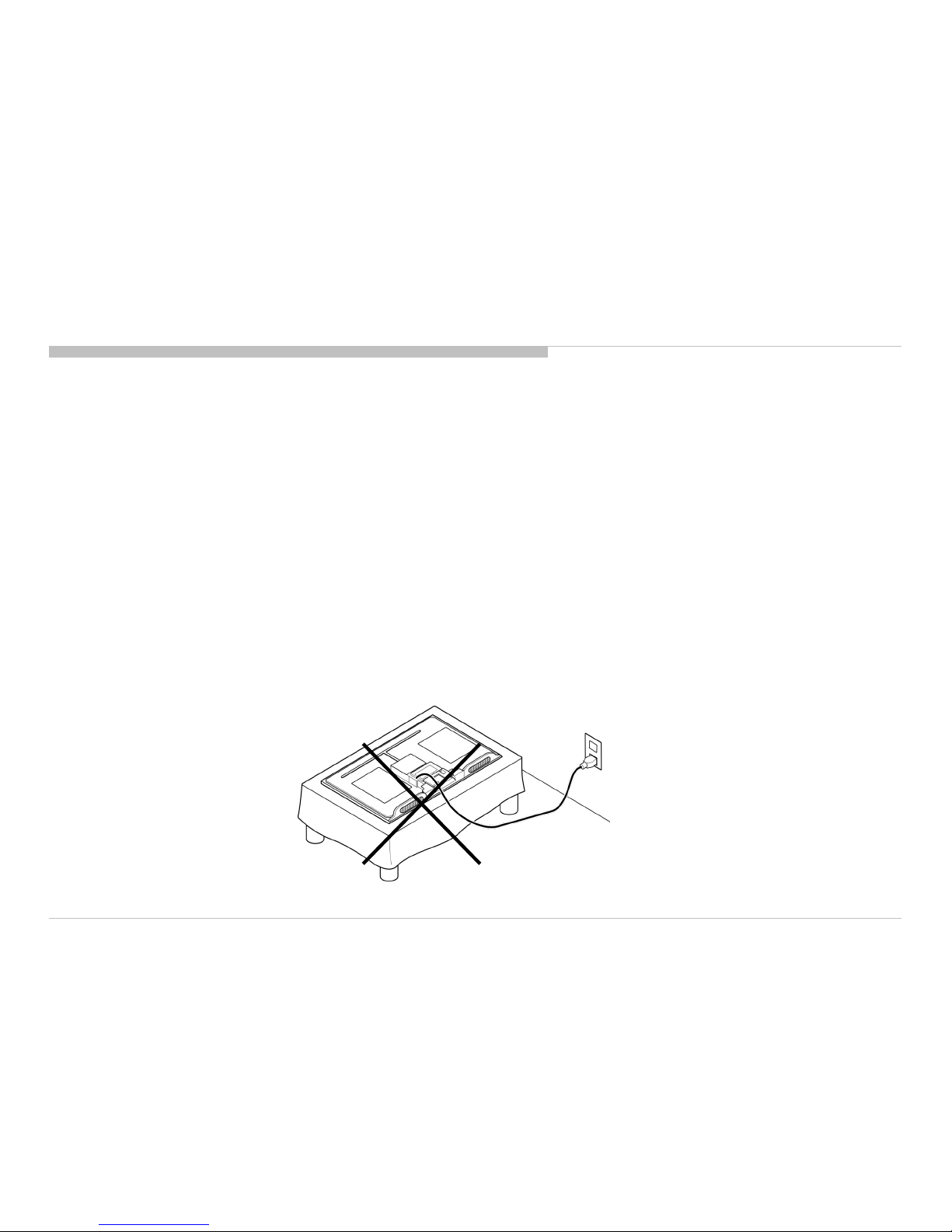
CARRYING THE TV
Be sure to follow these guidelines to protect your property and avoid causing serious injury.
• Carry the TV with an adequate number of people; larger size TVs require two or more people.
• Correct hand placement while carrying the TV is very important for safety and to avoid damages.
SAFETY-RELATED COMPONENT WARNING!!
Components identified by shading and mark on the schematic diagrams, exploded views, and in the parts list are critical for safe operation. Replace these components with Sony
parts whose part numbers appear as shown in this manual or in supplements published by Sony. Circuit adjustments that are critical for safe operation are identified in this manual.
Follow these procedures whenever critical components are replaced or improper operation is suspected.
CAUTION ABOUT THE LITHIUM BATTERY
• Danger of explosion if battery is incorrectly replaced. Replace only with the same or equivalent type.
• Outer case broken battery should not contact to water.
KDL-32R500C, 505C, 507C, 40/48R510C, 550C, 555C, 557C
4 4
WARNINGS AND CAUTIONS - ENGLISH

ATTENTION!!
Ces instructions de service sont à l’usage du personnel de service qualifi é seulement.
Pour prévenir le risque de choc électrique, ne pas faire l’entretien autre que celui contenu dans le Mode d’emploi à moins que vous soyez qualifi é faire ainsi.
WARNING!!
Afi n d’eviter tout risque d’electrocution provenant d’un chássis sous tension, un transformateur d’isolement doit etre utilisé lors de tout dépannage. Le chássis de ce récepteur est
directement raccordé à l’alimentation du secteur.
POUR TRANSPORTER LE TÉLÉVISEUR
Tenez compte de ce qui suit pendant l’installation du téléviseur :
• Débranchez tous les câbles avant de transporter le téléviseur.
• Transportez le téléviseur avec le nombre de personnes approprié ; un téléviseur de grande taille doit être transporté par au moins deux personnes.
• Lors du transport du téléviseur, l’emplacement des mains est très important pour votre sécurité, ainsi que pour éviter de causer des dommages.
ALERTE!!
Afi n d’eviter tout risque d’electrocution provenant d’un chassis sous tension, un transformateur d’isolement doit etre utilise lors de tout depannage. Le chassis de ce recepteur est
directement raccorde a l’alimentation du secteur.
ATTENTION AUX COMPOSANTS RELATIFS A LA SECURITE!!
Les composants identifi es par une trame et par une marque sur les schemas de principe, les vues explosees et les listes de pieces sont d’une importance critique pour la securite
du fonctionnement. Ne les remplacer que par des composants Sony dont le numero de piece est indique dans le present manuel ou dans des supplements publies par Sony. Les
reglages de circuit dont l’importance est critique pour la securite du fonctionnement sont identifi es dans le present manuel. Suivre ces procedures lors de chaque remplacement de
composants critiques, ou lorsqu’un mauvais fonctionnement suspecte.
KDL-32R500C, 505C, 507C, 40/48R510C, 550C, 555C, 557C
5 5
WARNINGS AND CAUTIONS - FRENCH
KDL-32R500C, 505C, 507C, 40/48R510C, 550C, 555C, 557C
6
WARNINGS AND CAUTIONS
USE CAUTION WHEN HANDLING THE LCD PANEL
When repairing the LCD panel, be sure you are grounded by using a wrist band.
When repairing the LCD panel on the wall, the LCD panel must be secured using the 4 mounting holes on the rear cover.
1) Do not press on the panel or frame edge to avoid the risk of electric shock.
2) Do not scratch or press on the panel with any sharp objects.
3) Do not leave the module in high temperatures or in areas of high humidity for an extended period of time.
4) Do not expose the LCD panel to direct sunlight.
5) Avoid contact with water. It may cause a short circuit within the module.
6) Disconnect the AC power when replacing the backlight (CCFL) or inverter circuit. (High voltage occurs at the inverter circuit at 650Vrms.)
7) Always clean the LCD panel with a soft cloth material.
8) Use care when handling the wires or connectors of the inverter circuit. Damaging the wires may cause a short.
9) Protect the panel from ESD to avoid damaging the electronic circuit (C-MOS).
10) It is recommended not to exceed 1 hour of Power-On nor Burn-in period with LCD panel face down condition, in repair activity.

KDL-32R500C, 505C, 507C, 40/48R510C, 550C, 555C, 557C
7 7
SAFETY CHECK-OUT
After correcting the original service problem, perform the following safety checks before releasing the set to the customer:
1. Check the area of your repair for unsoldered or poorly soldered connections. Check the entire board surface for solder splashes and bridges.
2. Check the interboard wiring to ensure that no wires are “pinched” or touching high-wattage resistors.
3. Check that all control knobs, shields, covers, ground straps, and mounting hardware have been replaced. Be absolutely certain that you have replaced all the insulators.
4. Look for unauthorized replacement parts, particularly transistors, that were installed during a previous repair. Point them out to the customer and recommend their replacement.
5. Look for parts which, though functioning, show obvious signs of deterioration. Point them out to the customer and recommend their replacement.
6. Check the line cords for cracks and abrasion. Recommend the replacement of any such line cord to the customer.
7. Check the antenna terminals, metal trim, “metallized” knobs, screws, and all other exposed metal parts for AC leakage. Check leakage as described below.
8. For safety reasons, repairing the Power board and/or Inverter board is prohibited.
KDL-32R500C, 505C, 507C, 40/48R510C, 550C, 555C, 557C
8 8
SAFETY CHECK-OUT
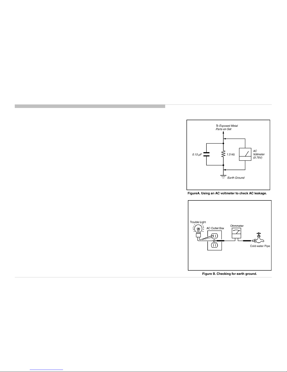
Leakage Test
The AC leakage from any exposed metal part to earth ground and from all exposed metal parts to any exposed
metal part having a return to chassis, must not exceed 0.5 mA (500 microamperes).
Leakage current can be measured by any one of three methods.
1. A commercial leakage tester, such as the Simpson 229 or RCA WT-540A. Follow the manufacturers’
instructions to use these instructions.
2. A battery-operated AC milliampmeter. The Data Precision 245 digital multimeter is suitable for this job.
3. Measuring the voltage drop across a resistor by means of a VOM or battery-operated AC voltmeter. The
“limit” indication is 0.75 V, so analog meters must have an accurate low voltage scale.
The Simpson’s 250 and Sanwa SH-63TRD are examples of passive VOMs that are suitable. Nearly all
battery-operated digital multimeters that have a 2 VAC range are suitable (see Figure A).
How to Find a Good Earth Ground
A cold-water pipe is a guaranteed earth ground; the cover-plate retaining screw on most AC outlet boxes is also
at earth ground.
If the retaining screw is to be used as your earth ground, verify that it is at ground by measuring the resistance
between it and a cold-water pipe with an ohmmeter. The reading should be zero ohms.
If a cold-water pipe is not accessible, connect a 60- to 100-watt trouble- light (not a neon lamp) between the hot
side of the receptacle and the retaining screw. Try both slots, if necessary, to locate the hot side on the line; the
lamp should light at normal brilliance if the screw is at ground potential (see Figure B).
9 9
SAFETY CHECK-OUT
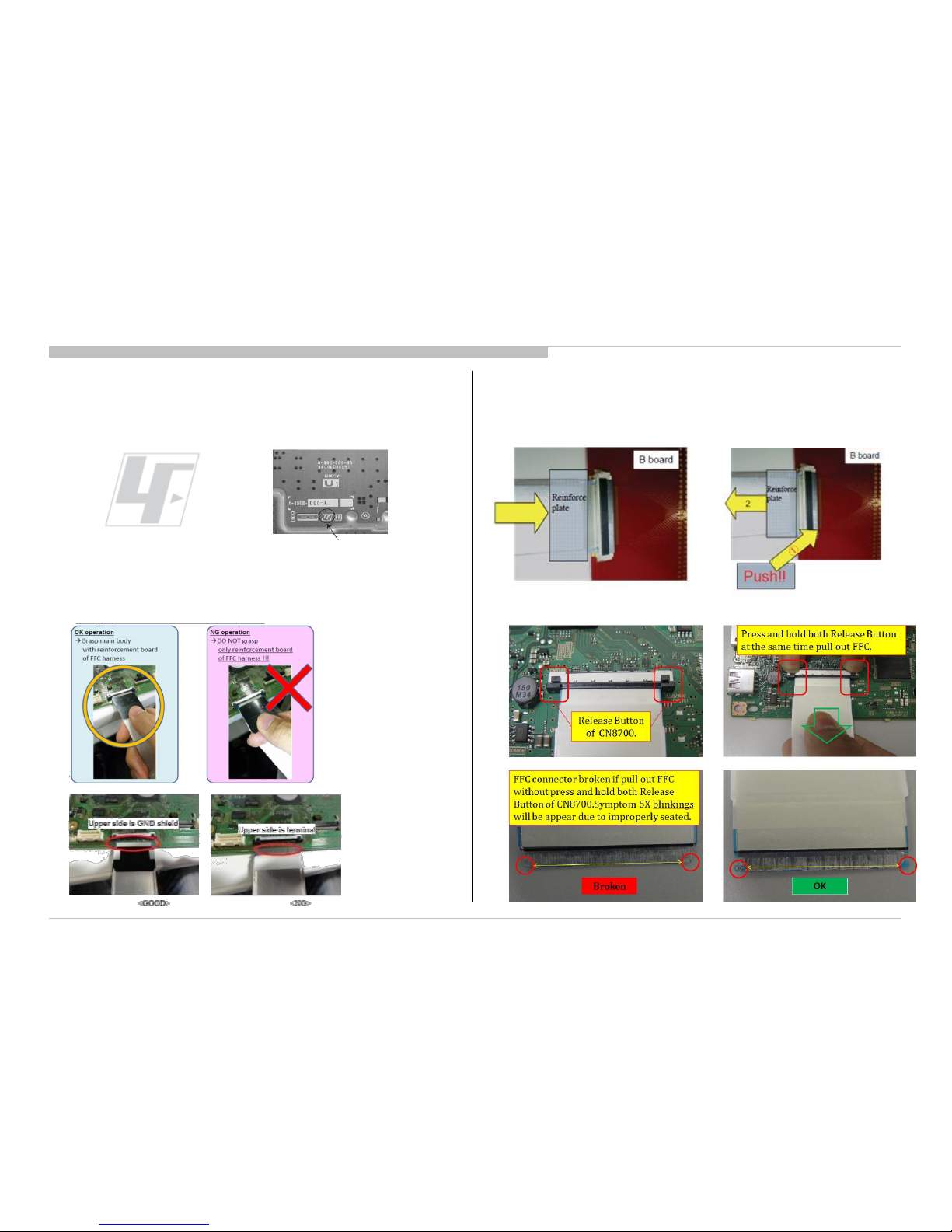
Lead Free Information
The circuit boards used in these models have been processed using Lead Free
Solder. The boards are identified by the LF logo located close to the board
designation.
Handling the FLEXIBLE FLAT CABLE (FFC)
When you insert / pull out FFC, please grasp a reinforcement board and main
body of FFC
Figure 4: LF Logo
Figure 5: LF logo on circuit board
Please hold reinforcement board and plunge
it to depths.
Please pull out FFC while pushing the
button of both ends at the same time.
< Insertion>
<Pull out>
KDL-32R500C, 505C, 507C, 40/48R510C, 550C, 555C, 557C
KDL-32R500C, 505C, 507C, 40/48R510C, 550C, 555C, 557C
10
SELF DIAGNOSIS FUNCTION
ABOUT ILLUMINAITION LED
OUTLINE OF SELF DIAGNOSIS FUNCTION
The units in this manual contain a self-diagnostic function. If an error occurs, the STANDBY LED will automatically begin to flash.
The number of times the LED flashes translates to a probable source of the problem.
A definition of the STANDBY LED flash indicators is listed in the instruction manual for the user’s knowledge and reference.
If an error symptom cannot be reproduced, the remote commander can be used to review the failure occurrence data stored in memory to reveal past problems and
how often these problems occur.
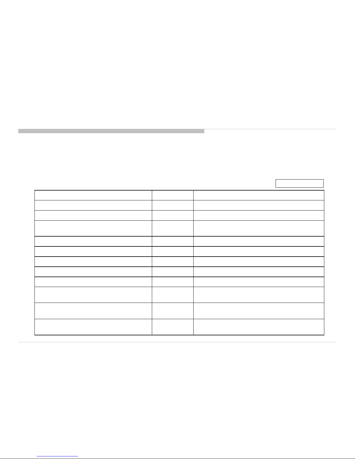
Status LED Color Remarks
Power Off ( AC Off and *1) OFF *1 power switch off (by touch button)
Power On Green
Standby(by remote control off and Side Key off) OFF
Picture Off Green
Set "Sleep Timer" Amber
Set "On Timer” ( Power On ) Amber
Set "On Timer”( Standby ) Amber
Picture Frame Amber
Failure Red Blinking The number of LED blinking indicates cause of failure.
Error of panel ID
Amber/Green
Blinking
Blinking:0.5sec Amber/ 0.5sec Green
Software Updating
Amber
Blinking
Blinking: 1sec On / 1sec Off
Amber = Red + Green
SELF DIAGNOSIS FUNCTION
KDL-32R500C, 505C, 507C, 40/48R510C, 550C, 555C, 557C
11
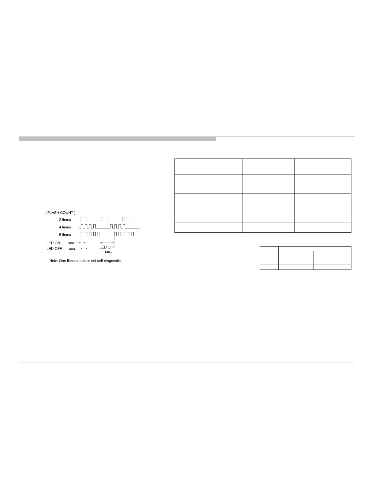
DIAGNOSTIC TEST INDICATORS
When an error occurs, the STANDBY LED will flash a set number of times to
indicate the possible cause of the problem.
If there is more than one error, the LED will identify the first of the problem areas.
Result for all of the following diagnostic items are displayed on screen.
If the screen displays a “0”, no error has occurred .
0.5
0.5
3
DISPLAY OF STANDBY LED FLASH COUNT
The Number of Standby LED
(RED blinking)
Error Detection Error Location
2 Main Power Error AC adapter Error
3 Audio Error B* board Error
4 Panel Power Error B* board Error
5 Panel I2C COMM Error B* or Source board Error
6 Backlight Error B* board Error
7 Subwoofer Error B* board Error
Size
B* Board Type
PAN ASIA,AMERICA
EUROPE
32” BA BE
40” BA BE
i+ (info)
KDL-32R500C, 505C, 507C, 40/48R510C, 550C, 555C, 557C
12
SELF DIAGNOSIS FUNCTION
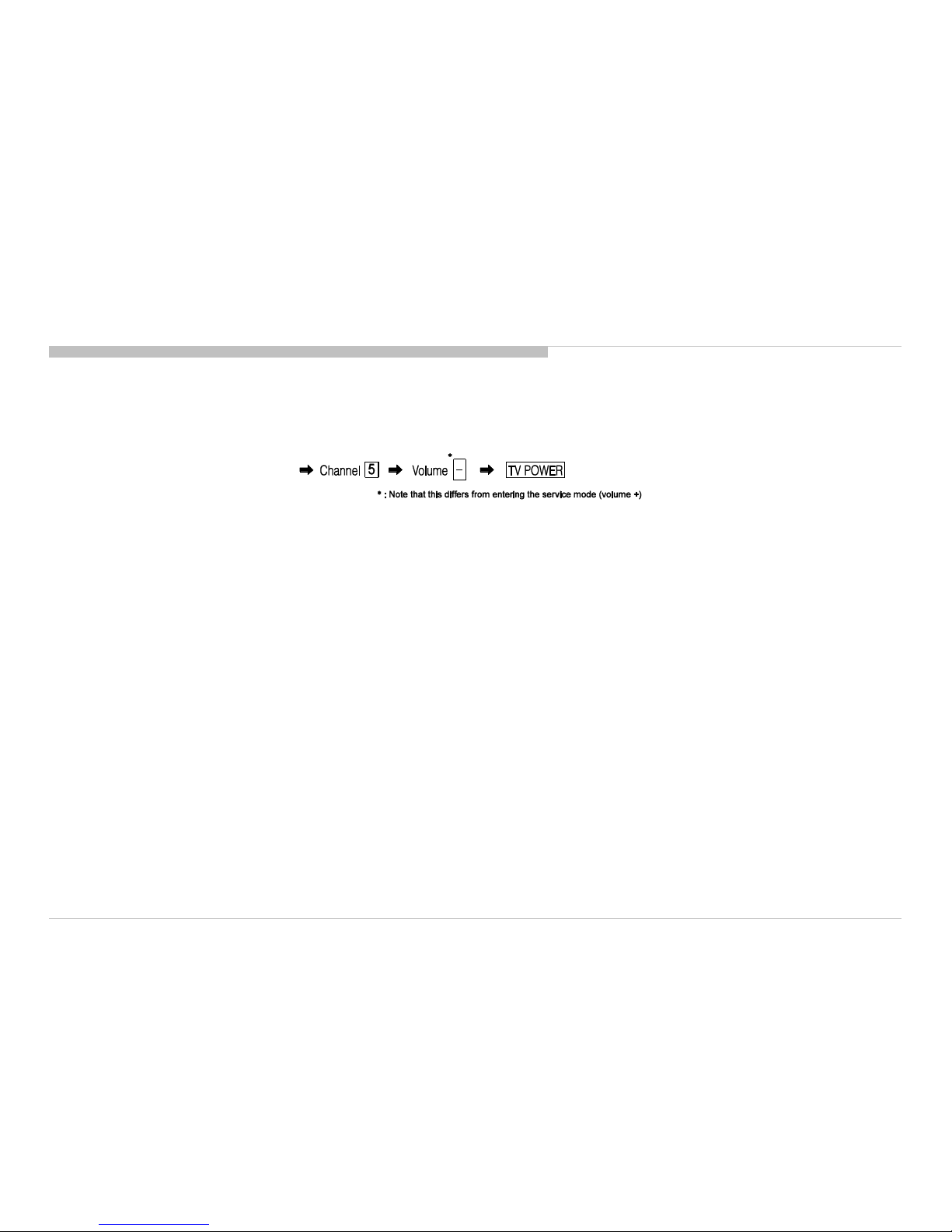
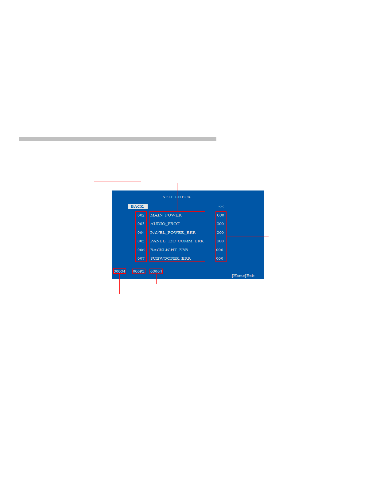
SELF-DIAGNOSTIC SCREEN DISPLAY
For errors with symptoms such as “power sometimes shuts off” or “screen sometimes goes out” that cannot be confirmed, it is p ossible to bring up past occurrences of failure for
confirmation on the screen:
[To Bring Up Screen Test]
In standby mode, press buttons on the remote commander sequentially in rapid succession as shown below:
Since the diagnostic results displayed on the screen are not automatically cleared, always check the self-diagnostic screen.
After you have completed the repairs, clear the result display to “0”.
Clearing the Self Check Diagnostic List
1. Error history and Error count : Press the Channel 8 => Channel 0 .
2. Panel operation time : Press the Channel 7 => Channel 0 .
Exiting the Self-diagnostic screen
To exit the Self Diagnostic screen, turn off the power to the TV by pressing the POWER button on the remote or the POWER button on the TV.
KDL-32R500C, 505C, 507C, 40/48R510C, 550C, 555C, 557C
13
SELF DIAGNOSIS FUNCTION
[SELF DIAGNOSTIC SAMPLE SCREEN DISPLAY]
Error count
Error name
Number of Standby
LED flashings
Total operation time by hour (MAX:65535)
Boot count (MAX:65535)
Panel operation time by hour (MAX:65535)
0- indicates no error was
detected.
1- indicates an error was
detected.
• Items with no part number and no description are not stocked because they are seldom required for routine service.
• The construction parts of an assembled part are indicated with a collation number in the remark column.
• Items marked " * " are not stocked since they are seldom required for routine service. Some delay should be anticipated when ordering these items.
14
SEC 1. DISASSEMBLY AND PARTS LIST
KDL-32R500C, 505C, 507C, 40/48R510C, 550C, 555C, 557C
Note: About the rear cover disassembly method, please refer to “APPENDIX-2”.
15
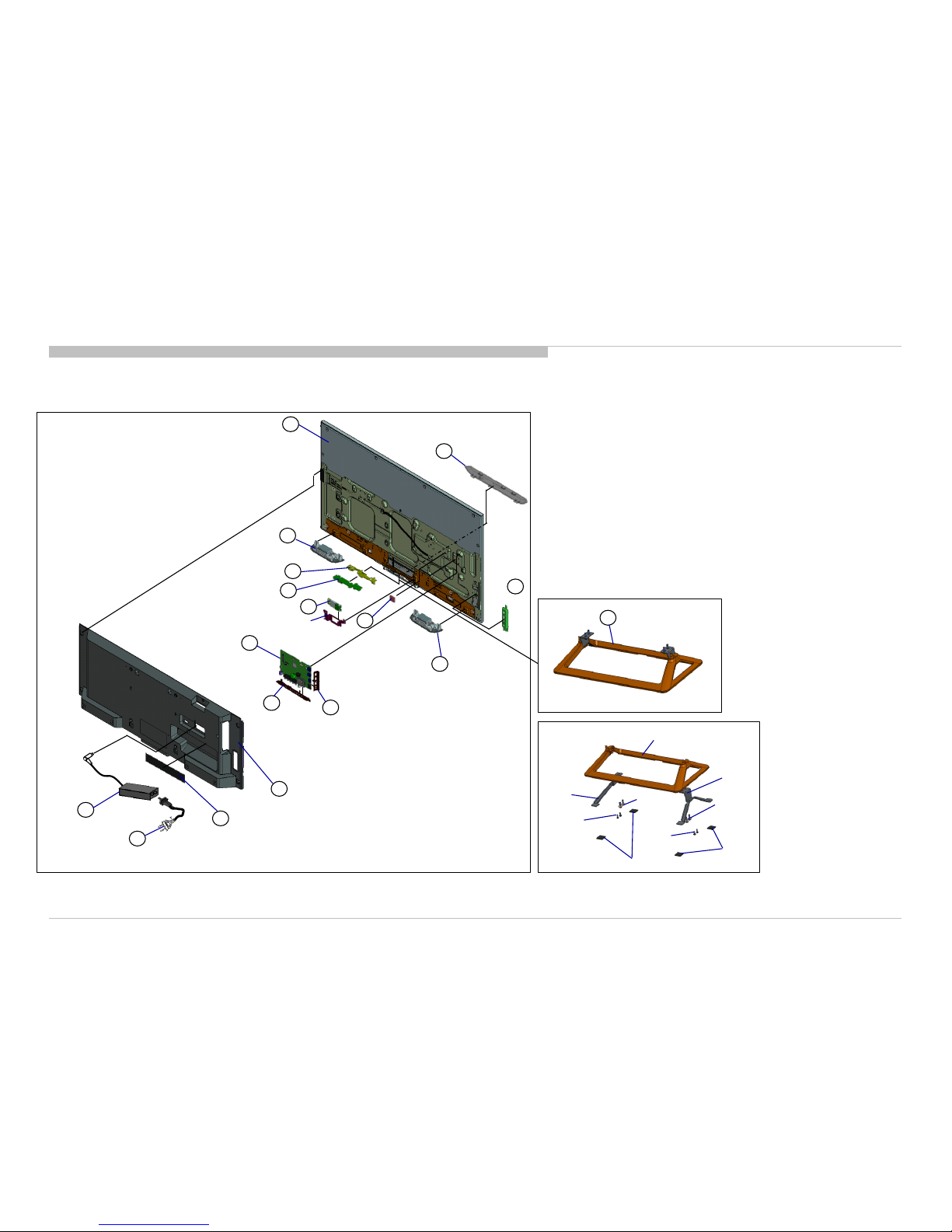
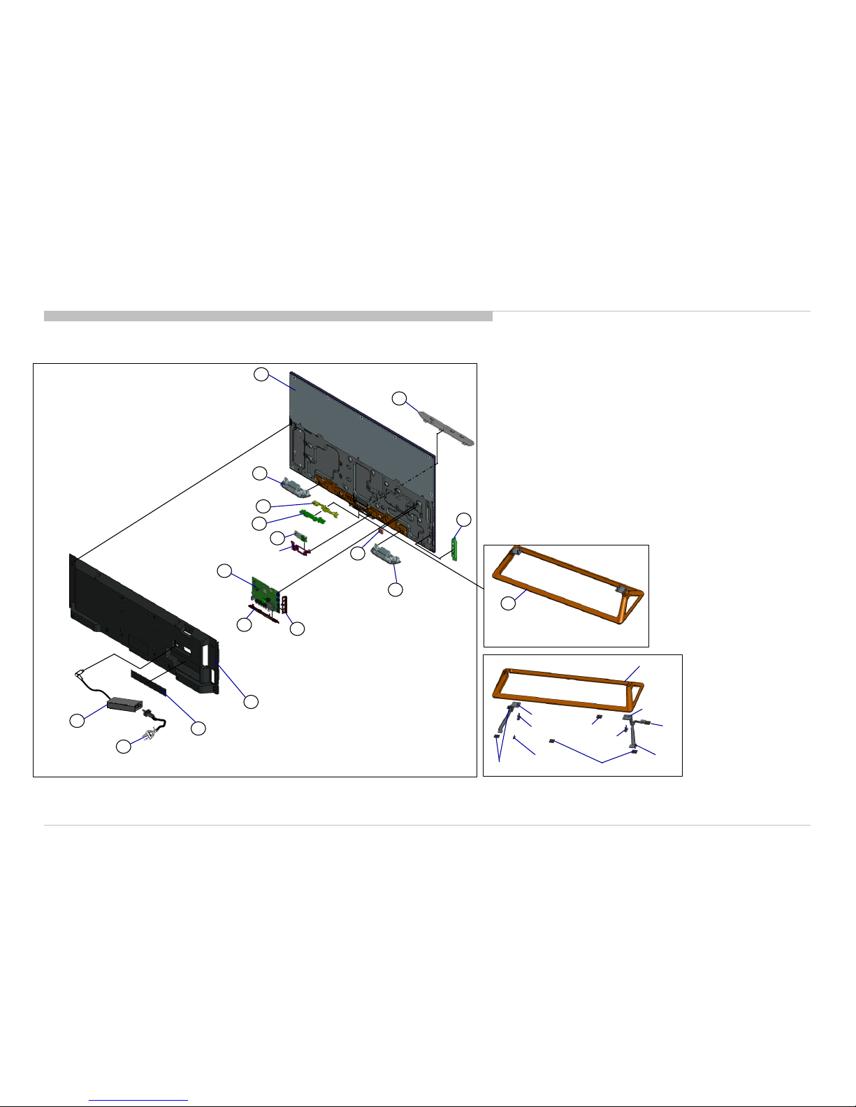
1-1. KDL-32R500C/505C/507C
1-1-1. Disassembly, Exploded View
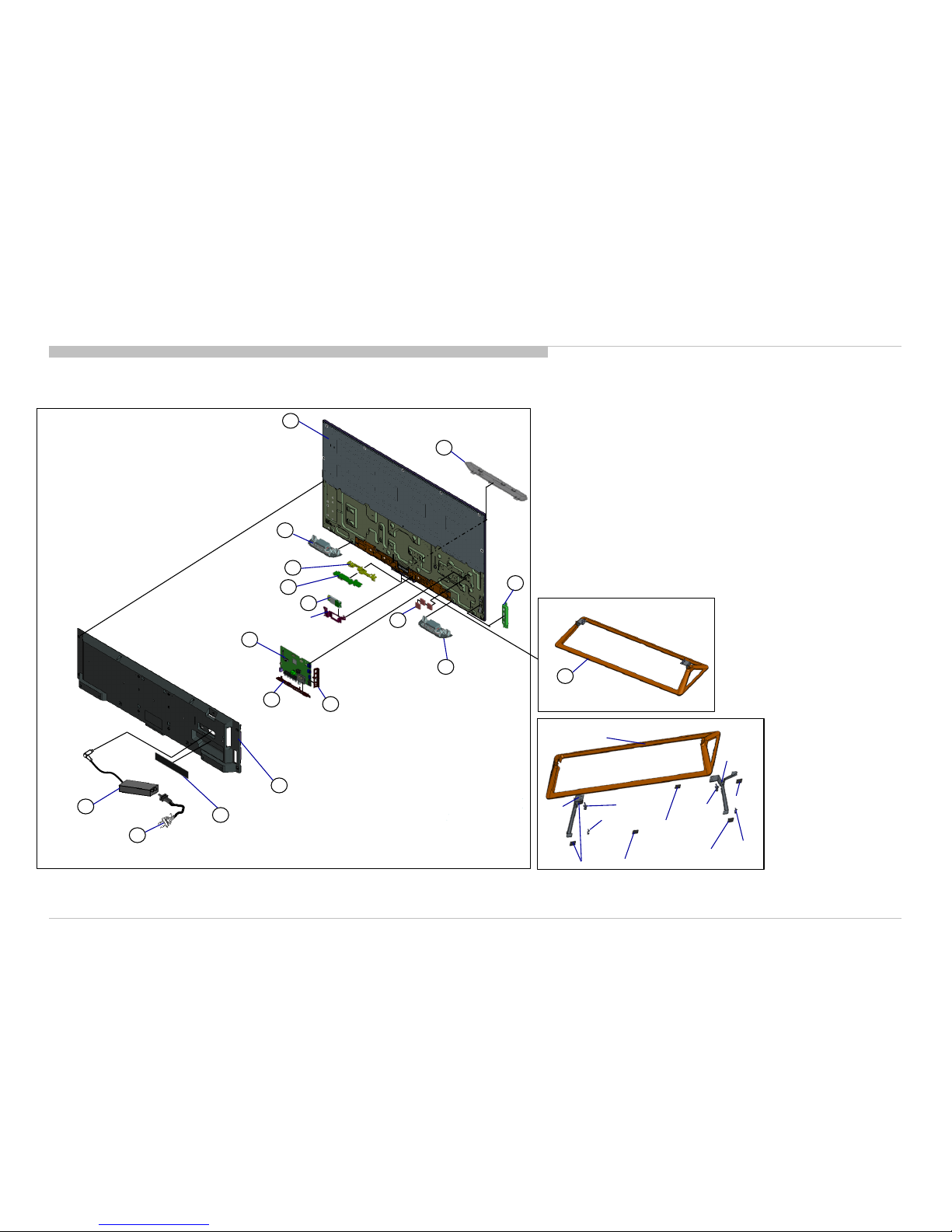
DISASSEMBLY AND PARTS LIST
KDL-32R500C, 505C, 507C, 40/48R510C, 550C, 555C, 557C
9
BA BOARD
8
BRACKET SIDE
7
BRACKET UNDER
P-MOD
15
5
REAR COVER
4
LABEL, UNDER TERMINAL
POWER SUPPLY CORD
2
SHEET,
THERMAL
3
6
SWITCH
UNIT
10
LOUDSPEAKER
11
PANEL,
ORNAMENTAL
LOUDSPEAKER
11
1
AC ADAPTOR
This part is not stocked. The purpose of
indicated in this illustrator is just f or
reference only.
12
CARD, WIRELESS LAN
13
HKK BOARD
14
LIGHT, GUIDE
STAND BLOCK
STAND BASE ASSY S
71
STAND BASE S
STAND
METAL L S
SCREW,
+PSW
M4X12
FOOT,STAND
SCREW
+BVTP
3X10
SCREW,
+PSW
M4X12
STAND METAL R S
FOOT,STAND
SCREW
+BVTP
3X10
REF. No. PART No. DESCRIPTION MARK
1 1-492-997-11 AC ADAPTOR (45W)
2 1-846-090-31 CORD SET, POWER-SUPPLY CO1/UC2
2 1-846-420-11 CORD SET, POWER-SUPPLY LA8/CR1/ECU
3 4-566-496-01 PANEL, ORNAMENTAL (OWL)
4 4-549-627-01 LABEL, UNDER TERMINAL UC2
4 4-549-627-11 LABEL, UNDER TERMINAL CO1/LA8/CR1/ECU
5 4-566-589-01 REAR COVER (32OWL) A UC2
5 4-566-589-11 REAR COVER (32OWL) A CO1/LA8/CR1/ECU
6 1-492-517-21 SWITCH UNIT
7 4-565-427-01 BRACKET, UNDER (OWL) UC2
7 4-565-427-11 BRACKET, UNDER (OWL) CO1/LA8/CR1/ECU
8 4-565-416-11 BRACKET, SIDE (OWL)
9 A-2066-876-B COMPL SVC BA_SE2N_BR_32W LA8/CR1/ECU
9 A-2066-906-B COMPL SVC BA_SE2N_LA_32W CO1
9 A-2066-938-B COMPL SVC BA_SE2N_UC_32W UC2
10 4-564-765-01 SHEET,THERMAL(5595)
11 1-859-099-11 LOUDSPEAKER
12 1-458-751-21 CARD, WIRELESS LAN
13 A-2066-599-A HKK(MOUNT)
14 4-566-498-01 LIGHT, GUIDE (OWL)
15 A-2069-838-A P-MOD (IS5F320VNO0101)
16
1-1. KDL-32R500C/505C/507C
1-1-1. Disassembly, Exploded View
REF. No. PART No. DESCRIPTION MARK
71 4-566-394-21 STAND BASE ASSY S (OWL)
DISASSEMBLY AND PARTS LIST
KDL-32R500C, 505C, 507C, 40/48R510C, 550C, 555C, 557C
17
Ref Part No
Description
4-167-019-21
SCREW, +PSW M3X8
2-580-602-01
SCREW, +PSW M4X12
2-990-421-41
SCREW (+PSW) (M3X6)
7-685-647-79
SCREW +BVTP 3X10 TYPE2 IT
-3
1-1. KDL-32R500C/505C/507C
1-1-2. Screws
DISASSEMBLY AND PARTS LIST
KDL-32R500C, 505C, 507C, 40/48R510C, 550C, 555C, 557C

18
REF. No. PART No. DESCRIPTION MARK
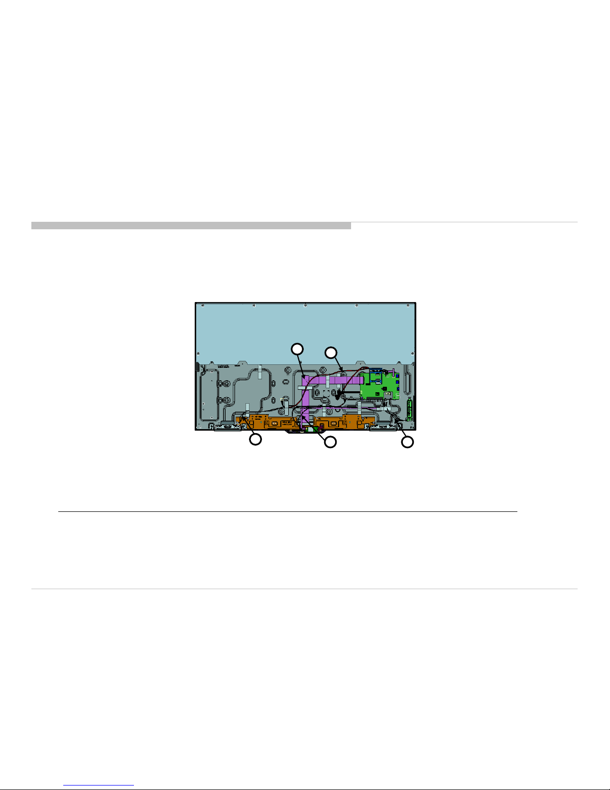
81 1-910-805-23 CONNECTOR ASSY 10P [CN9000(BA/BE)-(LS) (1)]
82 1-910-805-19 HARNESS ASSY [CN9700(BA)-(H-BOARD)-(TACT KEY) / CN4001(BA)-(SP) (1)]
83 1-848-838-11 FLEXIBLE FLAT CABLE 5P [CN9701(BA/BE)-(WIFI) (1)]
84 1-848-853-11 FLEXIBLE FLAT CABLE 30P [CN8601(BA/BE)-(SOURCE BOARD) (1)]
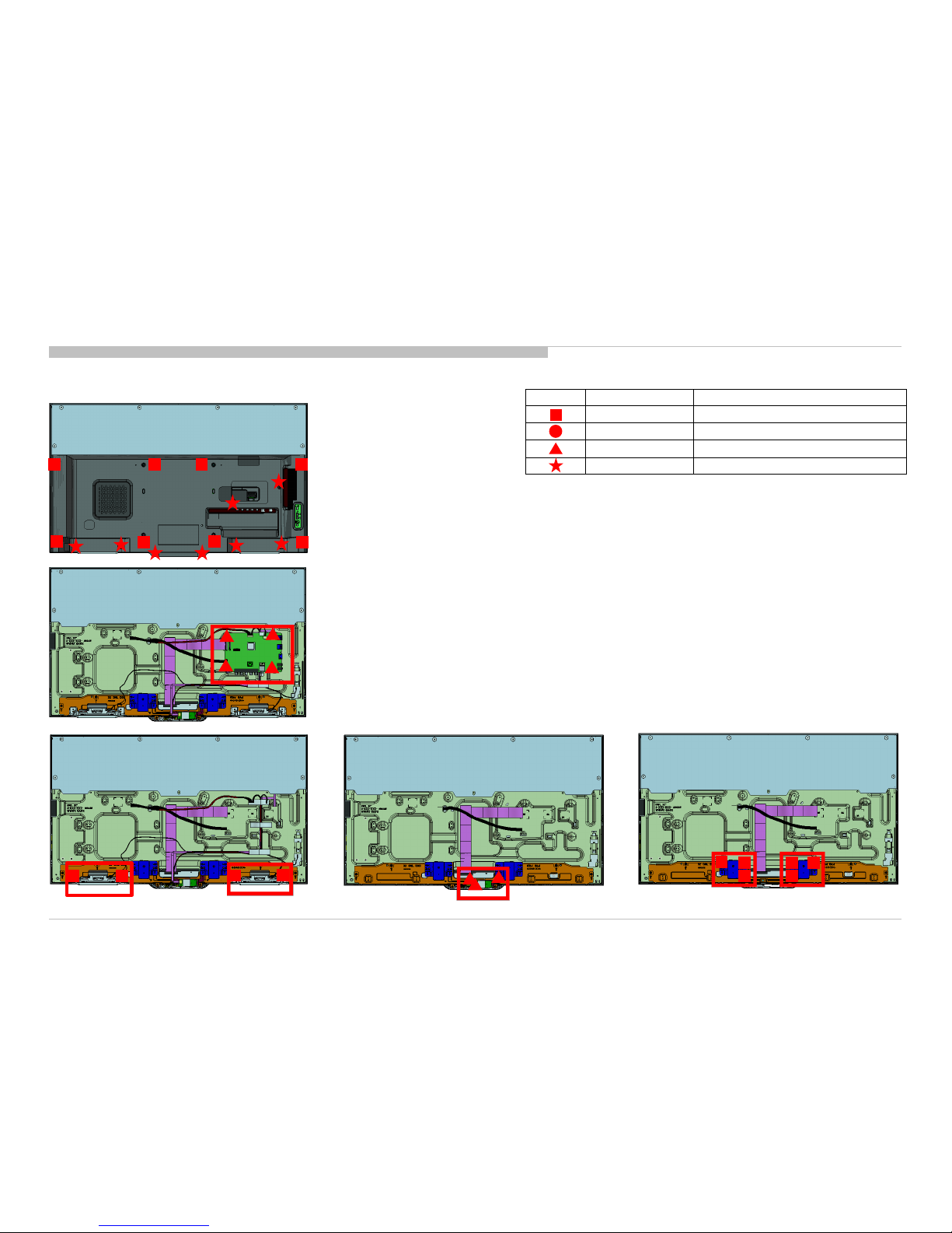
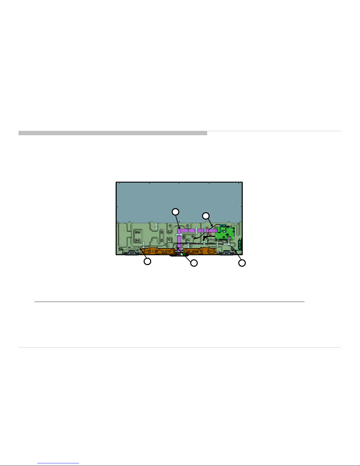
1-1. KDL-32R500C/505C/507C
1-1-3. Connectors
DISASSEMBLY AND PARTS LIST
KDL-32R500C, 505C, 507C, 40/48R510C, 550C, 555C, 557C
83
81
84
82
82
19
1-2. KDL-40R510C/550C/555C/557C
DISASSEMBLY AND PARTS LIST
1-2-1. Disassembly, Exploded View
KDL-32R500C, 505C, 507C, 40/48R510C, 550C, 555C, 557C
9
BA BOARD
8
BRACKET SIDE
7
BRACKET UNDER
19
P-MOD
15
5
REAR COVER
4
LABEL, UNDER TERMINAL
POWER SUPPLY CORD
2
SHEET,
THERMAL
3
6
SWITCH
UNIT
10
LOUDSPEAKER
11
PANEL,
ORNAMENTAL
LOUDSPEAKER
11
STAND BLOCK
1
AC ADAPTOR
This part is not stocked. The purpose of
indicated in this illustrator is just f or
reference only.
12
CARD, WIRELESS LAN
13
HKK BOARD
14
LIGHT, GUIDE
STAND BASE M
STAND
METAL L M
SCREW,
+PSW
M4X12
SCREW
+BVTP
3X10
FOOT,STAND
FOOT,STAND
FOOT,STAND
SCREW
+BVTP
3X10
SCREW, +PSW
M4X12
STAND METAL R M
FOOT,STAND
71
STAND BASE ASSY M
REF. No. PART No. DESCRIPTION MARK
1 1-493-001-11 AC ADAPTOR (60W)
2 1-846-090-31 CORD SET, POWER-SUPPLY CO1/U2/UC2/LA1
2 1-846-420-11 CORD SET, POWER-SUPPLY LA8/CR1/ECU
3 4-566-496-01 PANEL, ORNAMENTAL (OWL)
4 4-549-627-01 LABEL, UNDER TERMINAL U2/UC2/LA1
4 4-549-627-11 LABEL, UNDER TERMINAL LA8/CO1/CR1/ECU
5 4-566-593-01 REAR COVER (40OWL) A U2/UC2/LA1
5 4-566-593-11 REAR COVER (40OWL) A LA8/CO1/CR1/ECU
6 1-492-517-21 SWITCH UNIT
7 4-565-427-01 BRACKET, UNDER (OWL) U2/UC2/LA1
7 4-565-427-11 BRACKET, UNDER (OWL) LA8/CO1/CR1/ECU
8 4-565-416-11 BRACKET, SIDE (OWL)
9 A-2066-880-B COMPL SVC BA_SE2N_BR_40F LA8/CR1/ECU
9 A-2066-910-B COMPL SVC BA_SE2N_LA_40F CO1
9 A-2066-942-B COMPL SVC BA_SE2N_UC_40F U2/UC2/LA1
10 4-564-765-01 SHEET,THERMAL(5595)
11 1-859-099-11 LOUDSPEAKER
12 1-458-751-21 CARD, WIRELESS LAN
13 A-2066-599-A HKK(MOUNT)
14 4-566-498-01 LIGHT, GUIDE (OWL)
15 A-2069-842-A P-MOD (NS5F400VND0101)
20
DISASSEMBLY AND PARTS LIST
1-2. KDL-40R510C/550C/555C/557C
1-2-1. Disassembly, Exploded View
REF. No. PART No. DESCRIPTION MARK
71 4-566-395-21 STAND BASE ASSY M (OWL)
KDL-32R500C, 505C, 507C, 40/48R510C, 550C, 555C, 557C
Ref Part No
Description
7-685-647-79
SCREW +BVTP 3X10 TYPE2 IT
-3
2-990-421-41
SCREW (+PSW) (M3X6)
4-167-019-21
SCREW, +PSW M3X8
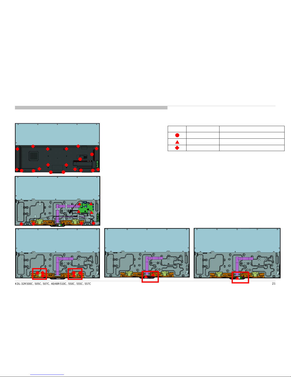
21
1-2. KDL-40R510C/550C/555C/557C
1-2-2. Screws
KDL-32R500C, 505C, 507C, 40/48R510C, 550C, 555C, 557C
DISASSEMBLY AND PARTS LIST
22
REF. No. PART No. DESCRIPTION MARK
81 1-910-805-29 CONNECTOR ASSY 10P [CN9000(BA/BE)-(LS) (1)]
82 1-910-805-25 HARNESS ASSY [CN9700(BA)-(H-BOARD)-(TACT KEY) / CN4001(BA)-(SP) (1)]
83 1-848-839-11 FLEXIBLE FLAT CABLE 5P [CN9701(BA/BE)-(WIFI) (1)]
84 1-848-842-11 FLEXIBLE FLAT CABLE 51P [CN8600(BA/BE)-(SOURCE BOARD)(1)]
1-2. KDL-40R510C/550C/555C/557C
1-2-3. Connectors
KDL-32R500C, 505C, 507C, 40/48R510C, 550C, 555C, 557C
DISASSEMBLY AND PARTS LIST
83
81
84
82
82
23
1-3. KDL-48R510C/550C/555C/557C
DISASSEMBLY AND PARTS LIST
1-3-1. Disassembly, Exploded View
KDL-32R500C, 505C, 507C, 40/48R510C, 550C, 555C, 557C
23
9
BA BOARD
8
BRACKET SIDE
7
BRACKET UNDER
P-MOD
15
5
REAR COVER
4
LABEL, UNDER TERMINAL
POWER SUPPLY CORD
2
SHEET,
THERMAL
3
6
SWITCH
UNIT
10
LOUDSPEAKER
11
PANEL,
ORNAMENTAL
LOUDSPEAKER
11
STAND BLOCK
1
AC ADAPTOR
This part is not stocked. The purpose of
indicated in this illustrator is just f or
reference only.
12
CARD, WIRELESS LAN
13
HKK BOARD
14
LIGHT, GUIDE
STAND BASE ML
STAND METAL
L ML
SCREW,
+PSW M4X12
FOOT,STAND
FOOT,STAND
SCREW
+BVTP
3X10
SCREW, +PSW
M4X12
FOOT,STAND
FOOT,
STAND
STAND
METAL R
ML
71
STAND BASE ASSY ML
REF. No. PART No. DESCRIPTION MARK
1 1-492-996-12 AC ADAPTOR (85W) ECU
1 1-493-000-11 AC ADAPTOR (85W) except ECU
2 1-846-090-31 CORD SET, POWER-SUPPLY CO1/U2/UC2/LA1
2 1-846-420-11 CORD SET, POWER-SUPPLY LA8/CR1/ECU
2 1-846-607-11 POWER-SUPPLY CORD (SET) BR6
3 4-548-878-01 PANEL, ORNAMENTAL (OWL) BR6
3 4-566-496-01 PANEL, ORNAMENTAL (OWL) except BR6
4 4-549-627-01 LABEL, UNDER TERMINAL U2/UC2/LA1
4 4-549-627-11 LABEL, UNDER TERMINAL CO1/LA8/CR1/ECU/BR6
5 4-566-597-01 REAR COVER (48SGL) A U2/UC2/LA1
5 4-566-597-11 REAR COVER (48SGL) A CO1/LA8/CR1/ECU
5 A-2074-142-A REAR COVER (48SGL) A BR6 BR6
6 1-492-517-21 SWITCH UNIT
7 4-547-840-61 BRACKET, UNDER (OWL) BR6
7 4-565-427-01 BRACKET, UNDER (OWL) U2/UC2/LA1
7 4-565-427-11 BRACKET, UNDER (OWL) CO1/LA8/CR1/ECU
8 4-547-839-41 BRACKET, SIDE (OWL) BR6
8 4-565-416-11 BRACKET, SIDE (OWL) except BR6
9 A-2066-884-B COMPL SVC BA_SE2N_BR_48F LA8/CR1/ECU/BR6
9 A-2066-914-B COMPL SVC BA_SE2N_LA_48F CO1
9 A-2066-952-B COMPL SVC BA_SE2N_UC_48F U2/UC2/LA1
10 4-564-765-01 SHEET, THERMAL(5595)
11 1-859-101-11 LOUDSPEAKER except BR6
11 A-2073-687-A LOUD SPEAKER ASSY SE2N 48INCH BR6
12 1-458-751-21 CARD, WIRELESS LAN except BR6
12 1-458-751-41 CARD, WIRELESS LAN BR6
13 A-2066-599-A HKK (MOUNT)
14 4-549-024-01 LIGHT, GUIDE (OWL) BR6
14 4-566-498-01 LIGHT, GUIDE (OWL) except BR6
15 A-2061-934-A P-MOD (NS5S480VND0101) BR6
15 A-2069-846-A P-MOD (NS5F480VND0101) except BR6
24
DISASSEMBLY AND PARTS LIST
1-3. KDL-48R510C/550C/555C/557C
1-3-1. Disassembly, Exploded View
REF. No. PART No. DESCRIPTION MARK
71 4-566-396-21 STAND BASE ASSY ML (SGL) except BR6
71 A-2072-349-A STAND BASE ASSY ML (SGL) BR6
KDL-32R500C, 505C, 507C, 40/48R510C, 550C, 555C, 557C
Ref Part No
Description
2-580-602-01
SCREW, +PSW M4X12
2-990-421-41
SCREW (+PSW) (M3X6)
4-167-019-21
SCREW, +PSW M3X8
4-472-518-01
SCREW, +PSW M3X6
7-685-647-79
SCREW +BVTP 3X10 TYPE2 IT
-3
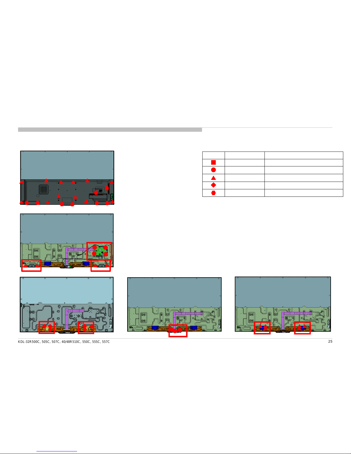
25
1-3. KDL-48R510C/550C/555C/557C
1-3-2. Screws
KDL-32R500C, 505C, 507C, 40/48R510C, 550C, 555C, 557C
DISASSEMBLY AND PARTS LIST
26
REF. No. PART No. DESCRIPTION MARK
81 1-910-805-35 CONNECTOR ASSY 10P [CN9000(BA/BE)-(LS) (1)]
82 1-910-805-31 HARNESS ASSY [CN9700(BA)-(H-BOARD)-(TACT KEY) / CN4001(BA)-(SP) (1)]
83 1-848-840-11 FLEXIBLE FLAT CABLE 5P [CN9701(BA/BE)-(WIFI) (1)]
84 1-848-844-11 FLEXIBLE FLAT CABLE 51P [CN8600(BA/BE)-(SOURCE BOARD) (1)] except BR6
84 1-848-904-11 FLEXIBLE FLAT CABLE 51P [CN8600(BA/BE)-(SOURCE BOARD) (1)] BR6
1-3. KDL-48R510C/550C/555C/557C
1-3-3. Connectors
KDL-32R500C, 505C, 507C, 40/48R510C, 550C, 555C, 557C
DISASSEMBLY AND PARTS LIST
83
81
84
82
82

PART No. DESCRIPTION MARK PART No. DESCRIPTION MARK
3-876-036-71 UNI-LABEL, BLANK 1-492-977-21 REMOTE COMMANDER (RMT-TX102B) CO1/LA8/
4-262-708-04 CLAMPER, CABLE CR1/ECU
2-580-602-01 SCREW, +PSW M4X12 1-492-977-31 REMOTE COMMANDER (RMT-TX102B) BR6
7-600-031-96 TAPE (3M 1350FW-1)15MMX66M WHT 1-492-980-11 REMOTE COMMANDER (RMT-TX102U) U2/UC2/LA1
7-600-031-97 TAPE (3M 1350FB-1)15MMX66M BLK 1-785-504-21 ADAPTOR, CONVERSION LA8/CR1/ECU
* 4-562-276-11 MANUAL, INSTRUCTION BR6
* 4-562-279-11 MANUAL, INSTRUCTION U2/UC2
* 4-562-282-31 MANUAL, INSTRUCTION LA8
* 4-562-284-31 MANUAL, INSTRUCTION CO1
* 4-562-287-31 MANUAL, INSTRUCTION LA1
* 4-566-298-31 MANUAL, INSTRUCTION CR1/ECU
27
1-4. OTHER PART
1-4-1. MISCELLANEOUS 1-4-2. ACCESSORIES
DISASSEMBLY AND PARTS LIST
KDL-32R500C, 505C, 507C, 40/48R510C, 550C, 555C, 557C
i+ (info)
KDL-32R500C, 505C, 507C, 40/48R510C, 550C, 555C, 557C
28
SEC 2. ADJUSTMENT
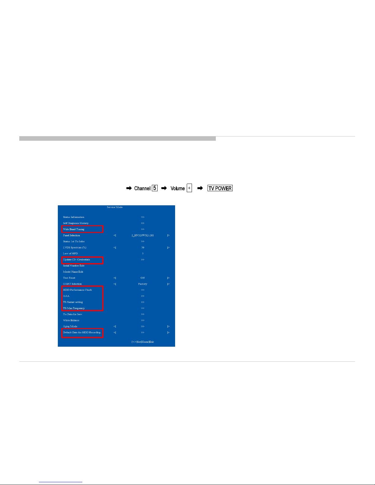
HOW TO ENTERING SERVICE MODE
1) Turn on the main power switch to place this set in standby mode.
2) Press the buttons on the remote commander as follows, and entering service mode.
3) Service mode display.
4) After entering service mode, then turn off the power switch.
KDL-32R500C, 505C, 507C, 40/48R510C, 550C, 555C, 557C
29
ADJUSTMENT
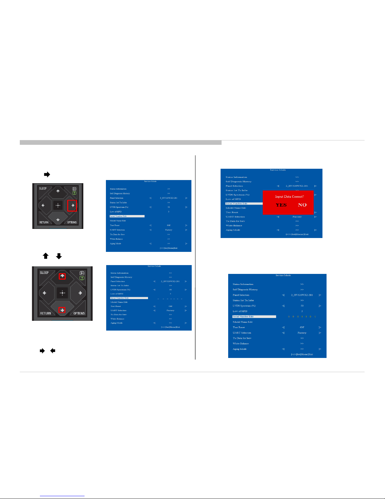
ACCESSING SERIAL NUMBER EDIT
3) Serial Number can be set ONLY ONCE.
After user input data , press <Enter>.
Pop dialog will appear to inform user to confirm data.
Press or button to select YES or NO.
Select YES if input data is correct.
Select NO if input data is incorrect.
Press <Enter> to save answer.
1) Press button on Remote to edit Serial Number.
Remote Commander
2) Press or button to select number.
Note: * The font color of YES is change to black when it is selected.
4) If YES is selected, the input data is saved into EEPROM.
SERIAL NUMBER EDIT is grayed out and the serial number that has
been input is displayed.
User will not able to edit anymore.
Note : * The font color of SERIAL NUMBER is change to orange
after YES is selected.
Remote Commander
* The font color of YES is change to black when it is selected.
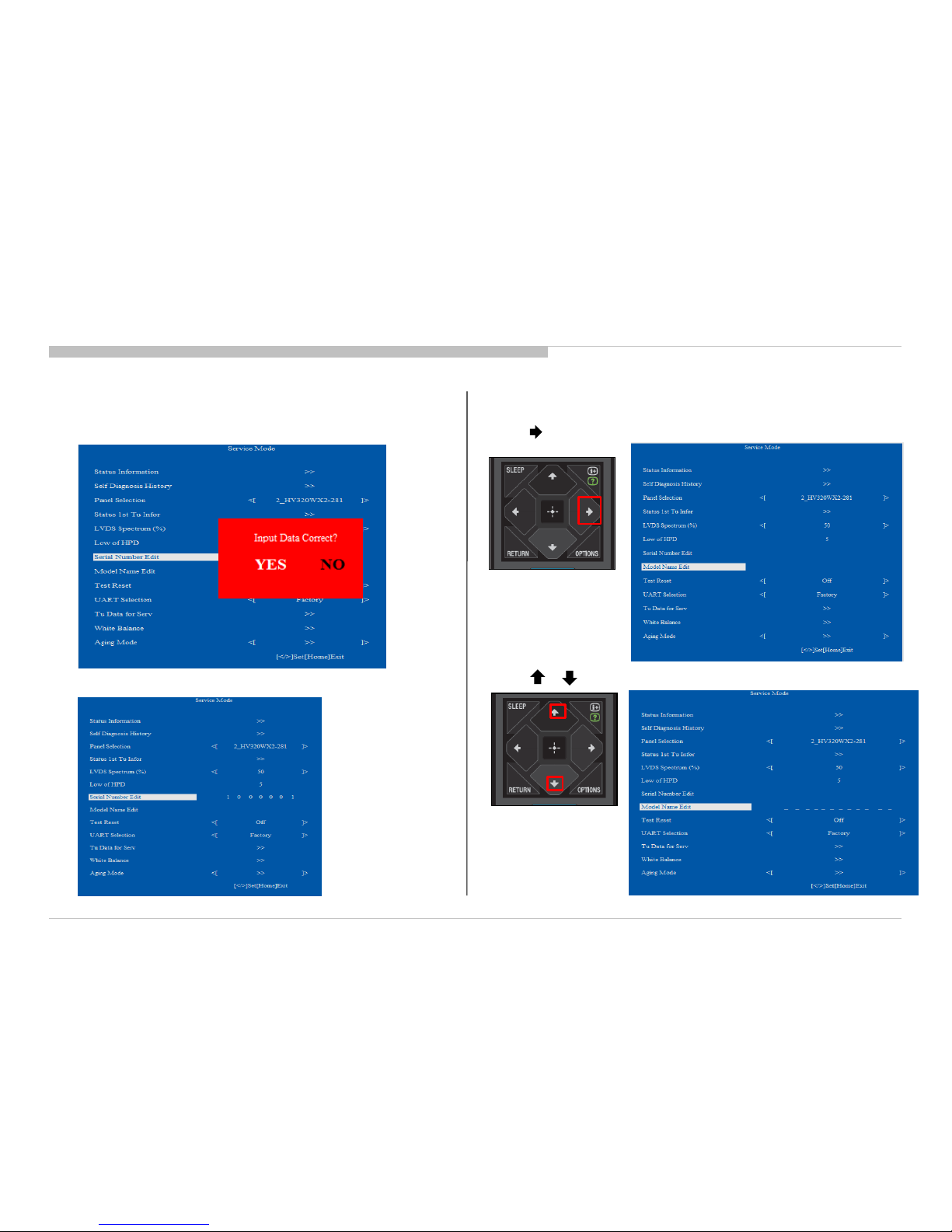
5) If NO is selected, the input data is not saved into EEPROM.
The serial number that has been input is displayed.
User can still edit the Serial Number.
KDL-32R500C, 505C, 507C, 40/48R510C, 550C, 555C, 557C
30
ADJUSTMENT
Note : * The font color of NO is change to black when it is selected.
Note : * The font color of SERIAL NUMBER is white after NO is selected.
1) Press button on Remote to edit Model Name.
2) Press or button on Remote to select character.
Remote Commander
Remote Commander
ACCESSING MODEL NAME EDIT
 Loading...