

Page 1
HISTORY INFORMATION FOR THE FOLLOWING MANUAL:
SERVICE MANUAL
ORIGINAL MANUAL ISSUE DATE: 3/2013
Version Date Subject
1.0 3/2013 Original manual issue.
1.1 10/2013 Correction of Panel Selection in Service mode. (P.19)
RB1FKCHASSIS
Segment: BA
LCD Digital Color TV
9-888-532-02
Page 2

SERVICE MANUAL
LCD Digital Color TV
RB1FKCHASSIS
Segment: BA
9-888-532-02
Page 3

MODEL LIST
MODEL COLOR COMMANDER DEST.
KDL-32R420A Black RM-ED054 AEP
KDL-32R421A Black RM-ED054 AEP
KDL-32R423A Black RM-ED054 AEP/UK
KDL-32R424A Black RM-ED054 AEP
KDL-40R470A Black RM-ED054 AEP
KDL-40R471A Black RM-ED054 AEP
KDL-40R473A Black RM-ED054 AEP/UK
KDL-40R474A Black RM-ED054 AEP
KDL-46R470A Black RM-ED054 AEP
KDL-46R473A Black RM-ED054 AEP/UK
MODEL COLOR COMMANDER DEST.
KDL-32R420A/421A/423A/424A , 40R470A/471A/473A/ 474A, 46R470A/473A(A EP/UK)
3
Page 4

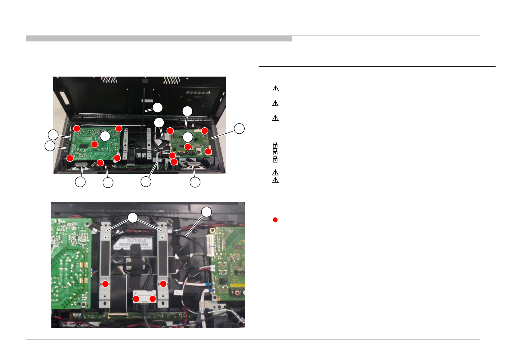
WARNINGS AND CAUTION S - ENGLISH
CAUTION
These servicing instructions are for use by qualified service personnel only.
To reduce the ri sk o f ele ct ri c sho c k, d o not perfo r m a ny se rvi ci ng other than that c o nta ine d i n the op e ra ti ng instr uc tio ns unless you are qualified to do so.
WARNING!!
An isolation transformer should be used during any service to avoid possible shock hazard, because of live chassis.
The chassis of this receiver is directly connected to the ac power line.
CARRYING THE TV
Be sure to follow these guidelines to protect your prop e r ty and avoid causing serious injury.
• Carry the TV with an adequate number of people; larger size TVs require two or more people.
• Correct hand placement while carrying the TV is very important for safety and to avoid damages.
SAFETY-RELATED COMPONENT WARNING!!
Components identified by shading and ! mark on the schematic diagrams, exploded views, and in the parts list are critical for safe operation. Replace these components with Sony
parts whose part numbers appear as shown in this manual or in supplements published by Sony. Circuit adjustments that are critical for safe operation are identified in this manual.
Follow these procedures whenever critical components are replaced or improper operation is suspected.
KDL-32R420A/421A/423A/424A , 40R470A/471A/473A/ 474A, 46R470A/473A(A EP/UK)
4
Page 5

WARNINGS AND CAUTION S - FRENCH
ATTENTION!!
Ces instructions de service sont à l’usage du personnel de service qualifi é seulement.
Pour prévenir le risque de choc électrique, ne pas faire l’entretien autre que celui contenu dans le Mode d’emploi à moins que vous soyez qualifi é faire ainsi.
WARNING!!
Afi n d’eviter tout risque d’electrocution provenant d’un chássis sous tension, un transformateur d’isolement d oit etre utilisé lors de tout dépannage. Le chássis de ce récep teur est
directement raccordé à l’alimentation du secteur.
POUR TRANSPORTER LE TÉLÉVISEUR
Tenez compte de ce qui suit pendant l’installation du téléviseur :
• Débranchez tous les câbles avant de transporter le téléviseur.
• Transportez le téléviseur avec le nombre de personnes approp r ié ; un téléviseur de grande taille doit être transporté par au moins deux per so nnes .
• Lors du transport du téléviseur, l’emplacement des mains est très important pour votre sécurité, ainsi que pour éviter de causer des dommages.
ALERTE!!
Afi n d’eviter tout risque d’electrocution provenant d’un chassis sous tension, un transformateur d’isolement d oit etre utilise lors de tout depannage. Le chassis de ce recep teur est
directement raccorde a l’alimentation du secteur.
ATTENTION AUX COMPOSANTS RELATIFS A LA SECURITE!!
Les composants identifi es par une trame et par une marque ! sur les schemas de principe, les vues explosees et les listes de pieces sont d’une importance critique pour la securite du
fonctionnement. Ne les remplacer que par des composants Sony dont le numero de piece est indique dans le present manuel ou dans des supplements publies par Sony. Les reglages
de circuit dont l’importance est critique pour la securite du fonctionnement sont identifi e s dans le present manuel. Suivre ces procedures lors de chaque remplacement de
composants cri tiques, ou lorsqu’un mauvais fonct ionnement suspe cte.
KDL-32R420A/421A/423A/424A , 40R470A/471A/473A/ 474A, 46R470A/473A(A EP/UK)
5
Page 6
USE CAUTION WHEN HANDLING T HE LCD PANEL
When repa ir ing the LCD p a nel, b e sure you ar e gro und ed b y using a wrist b and .
When repa ir ing the LCD p a nel o n the wall, the LCD panel must b e secur ed usi ng t he 4 mounting ho l es o n the r ea r c o ver .
1) Do not press on the panel or frame edge to avoid the risk of electric shock.
2) Do not scratch or press on the panel with any sharp objects.
3) Do not leave the module in high temperatures or in areas of high humidity for an extended period of t ime.
4) Do not expose the LCD panel to direct sunlight.
5) Avoid contact with water. It may c ause a short circuit within the module.
6) Disconnect the AC power when replacing the backlight (CCFL) or inverter circuit. (High voltage occurs at the inverter circuit at 650Vrms.)
7) Always clean the LCD panel with a soft cloth material.
8) Use care when handling the wires or connectors of the inverter circuit. Damaging the wires may cause a short.
9) Protect the panel from ESD to avoid damaging the electronic circuit (C-MOS).
10) It is recommended not to exceed 1 hour of Power-On nor Burn-in period with LCD panel face down condition, in repair activity.
WARNINGS AND C AUT IO NS
KDL-32R420A/421A/423A/424A , 40R470A/471A/473A/ 474A, 46R470A/473A(A EP/UK)
6
Page 7

SAFETY CHECK-OUT
After correcting the original service problem, perform the following safety checks before releasing the set to the customer:
1. Check the area of your repair for unsoldered o r poorly soldered connections. Check the entire board surface for solder splashes and bridges.
2. Check the interboard wiring to ensure that no wires are “pinched” or touching high-wattage resistors.
3. Check that all control knobs, shields, covers, ground straps, and mounting hardware have been replaced. B e absolutely certain that you have replaced all the insulators.
4. Look for unauthorized replacement parts, parti c ularly transistors, that were installed during a previous repair . Point them out to the customer and recommend their replacement.
5. Look for par ts which, though functioning, show obvio us signs o f d et er io r at io n. P o i nt them out to the custo mer and recommend their replacement.
6. Check the line cords for cracks and abrasion. Recommend the replacement of any such line cord to the customer.
7. Check the antenna terminals, metal trim, “metallized” knobs, screws, and all other exposed metal parts for AC leakage. Check leakage as described below.
8. For safety reasons, repairing the Power board and/or Inv ert er board is prohibited.
KDL-32R420A/421A/423A/424A , 40R470A/471A/473A/ 474A, 46R470A/473A(A EP/UK)
7
Page 8
Leakage Test
The AC leakage from any exposed metal part to earth ground and from all exposed m etal parts to any exposed
metal part having a return to chassis, must not exceed 0.5 mA (500 microamperes).
Leakage current can be m easured by any one of three m ethod s.
1. A commercial leakag e tester, such as the Simpson 229 or RCA WT-540A. Follow the manufacturers’
instructions to use these instructions.
2. A battery-operated AC milliampm ete r. The Data Precision 245 digital m ultim eter is suitable fo r this job.
3. Measuring the voltage d rop across a resistor by means of a VOM or battery-operated AC voltmeter. The
“limit” indication is 0.75 V, so analog meters must hav e an accurate low voltage scale.
The Simpson’s 250 and Sanwa SH-63TRD are examples of passive VO Ms that are suita bl e. Nearly all
battery-operated dig ital multim eters that have a 2 VAC range are suitable (see Figure A).
How to Find a Good Earth Ground
A cold-water pipe is a guaranteed earth ground; the cover-plate retaining screw on most AC outlet boxes is also
at earth ground.
If the retaining screw is to be used as your earth ground, verify that it is at ground by measuring the resistance
between it and a cold-water pipe with an ohmmeter. The reading should be zero ohms.
If a cold-water pipe is not accessible, connect a 60- to 100-watt trouble- light (not a neon lamp) between the hot
side of the receptacle and the retaining screw. Try both slots, if necessary, to locate the hot side on the line; the
lamp should light at normal brilliance if the screw is at ground potential (see Figure B).
SAFETY CHECK-OUT
KDL-32R420A/421A/423A/424A , 40R470A/471A/473A/ 474A, 46R470A/473A(A EP/UK)
8
Page 9
SELF DIAGNOSIS FUNCTION
STBY LED
F lash time
Service men u Item
name
(Screen Displ ay)
D iagn ostic Item D escript ion
2 MAIN_POWER Detect power boar d 12V. ( V_DROP_DET )
TUNER_ERR Detect TS signal Error.
AUDIO_PROT Det ec t A udio Amp Error .
DC_ALERT1 Detect +3. 3V+5V Drop. (V_DROP _DE T)
4
BALANCER_ERR Not used
TCON_ERR Not used
PANEL_POWE Not used
6 BACKLIGHT_ERR Detec t panel backlight r eady.
7
TEMP_ERR Not used
8 - Not used
9 - Not used
10 - Not used
11 - Not used
12 - Not used
3
5
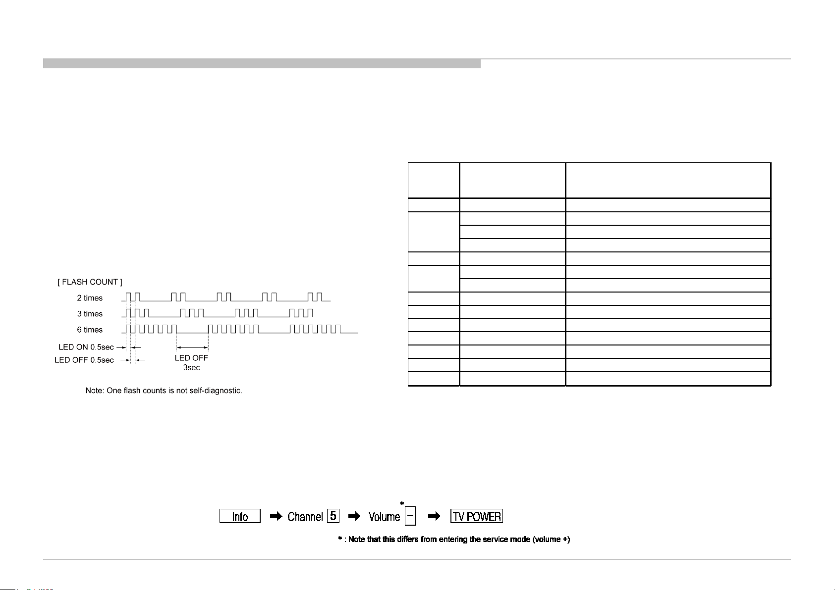
The units in this manual contain a self-diagnostic function. If an error occurs, the STANDBY LED will automatically b egin to flash.
The number of times the LED flashes translates to a probable source of the problem.
A definition of the STANDBY LED flash indicators is listed in the instruction manual for the user’s knowledge and r eference.
If an error symptom cannot be reproduced, the remote commander can be used to review the failure occurrence data stored in memory to reveal past problems and how often these
problems occur.
DIAGNOSTIC TEST INDICATORS
When an error occurs, the STANDBY LED will flash a set number of times to
indicate the possible cause of the problem.
If there is more than one error, the LED will identify the first of the problem areas.
Result for all of the following diagnostic items are displayed on screen.
If the screen displays a “0”, no error has occurred .
DISPLAY OF STANDBY LED FLASH COUNT
SELF-DIAGNOSTIC SCREEN DISPLAY
For errors with symptoms such as “power sometimes shuts off” or “screen sometimes goes out” that cannot be confirmed, it is possible to bring up past occurrences of failure for
confirmation on the screen:
[To Bring Up Screen Test]
In standby mode, press buttons on the remote commander sequentially in rapid succession as shown below:
KDL-32R420A/421A/423A/424A , 40R470A/471A/473A/ 474A, 46R470A/473A(A EP/UK)
9
Page 10
[SELF DIAGNOSTIC SCREEN DISPL AY]
SELF DIAGNOSIS FUNCTION
Item name
BACK <<
002 MAIN_POWER 000
003 TUNER_ERR 000
003 AUDIO_PROT 000
003 DC_ALERT1 000
SELF CHECK
STBY LED flash time
004 BALANCER_ERR 000
Error count
005 TCON_ERR 000
005 PANEL_POWE 000
006 BACKLIGHT_ERR 000
007 TEMP_ERR 000
12345-67891-23456
[Home] Exit
Panel operation time by hour
Boot count
Total operation time by hour
Since the diagnostic results displayed on the screen are not automatically cleared, always check the self-diagnostic screen.
After you have completed the repairs, clear the result display to “0”.
Clearing the Self Check Diagnostic List
1. Error history and Error count : Press the Channel 8 => Channel 0 .
2. Panel operation time : Press the Channel 7 => Channel 0 .
Exiting the Self-diagnostic screen
To exit the Self Diagnostic screen, turn off the power to the TV by pressing the POWER button on the remote or the POWER button on the TV.
KDL-32R420A/421A/423A/424A , 40R470A/471A/473A/ 474A, 46R470A/473A(A EP/UK)
10
Page 11

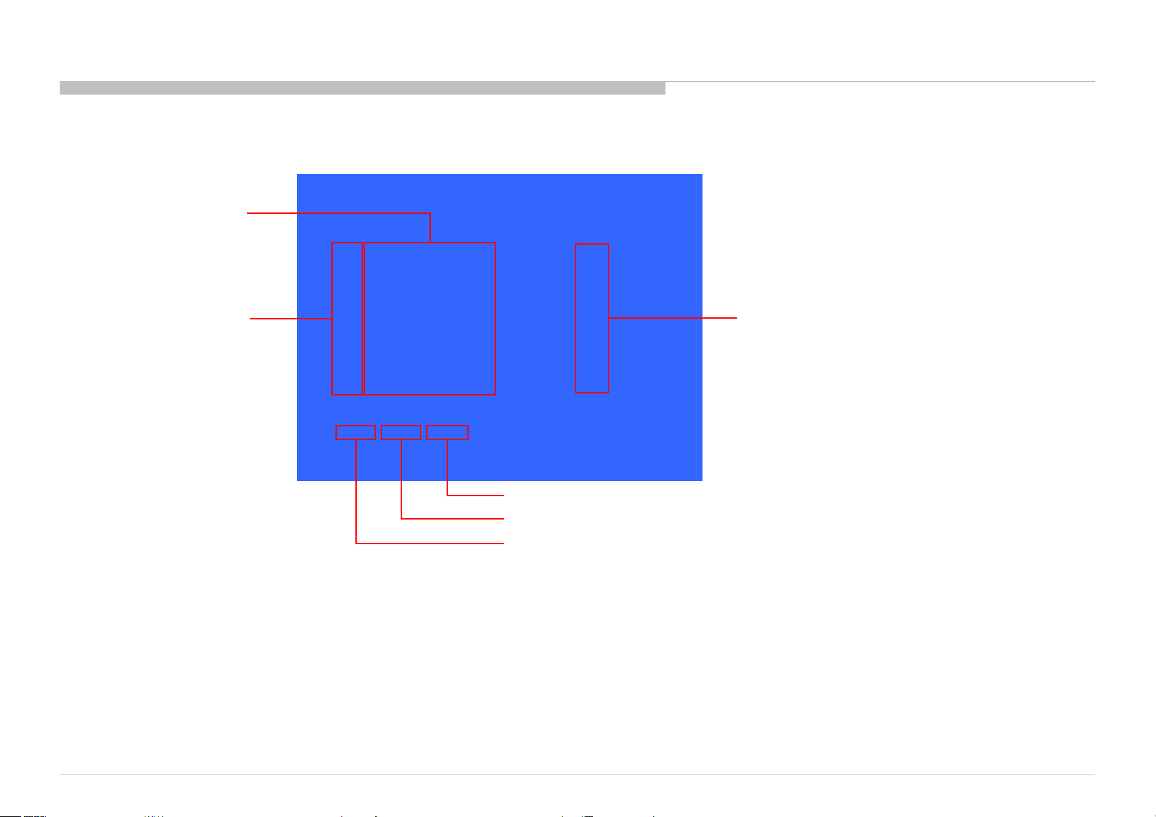
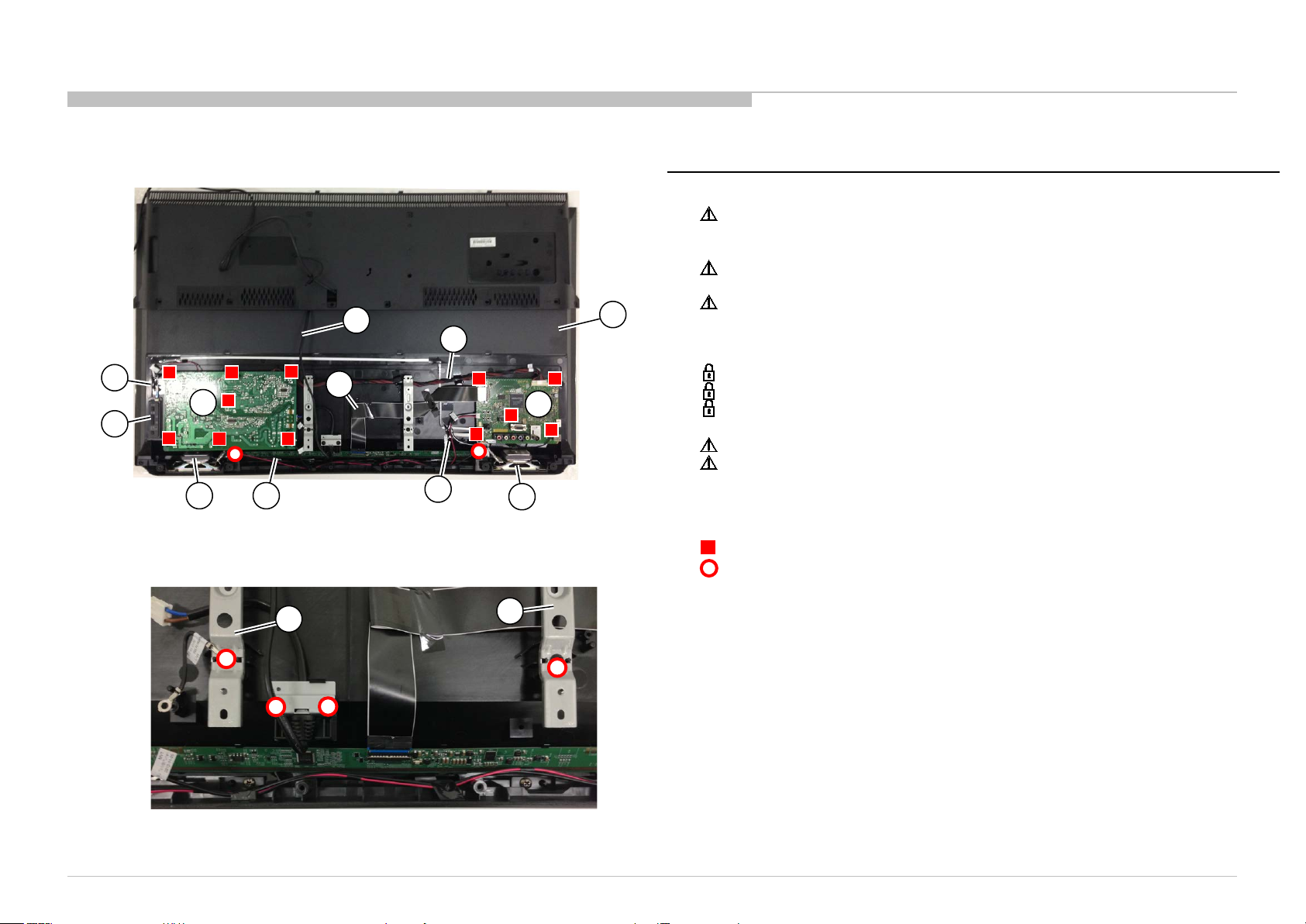
SEC 1. DISASSEMBLY AND PARTS LIST
• Items with no part number and no description are not stocked because they are seldom required for roution service.
• The construction parts of an assembled part are indicated with a collation number in the remark co lum.
• Items marked " * " are not stocked since they are seldom required for routine service. Some delay should be anticipated when ordering these items.
Note: About the wire dressing, please refer to “APPENDIX-1”.
Note: About the tape position, please refer to “APPENDIX-2”.
Note: About the procedure of switch unit disassembly method, please refer to “APPENDIX-3”.
KDL-32R420A/421A/423A/424A , 40R470A/471A/473A/ 474A, 46R470A/473A(A EP/UK)
11
Page 12
REF. No . PART No . DESCRIPTION MARK
1 4-446-634-01 STAND SHAFT (M2)
2 4-459-441-51 COV E R, UNDER (32F ANF ) for KDL-32R423A(UK )
4-459-441-61 COVER, UNDE R ( 32 FANF) for KDL- 32R420A/421A/
423A(A E P ) /424A
2-580-608-11 SCREW, +PSW M5X16
2-580-639-01 SCREW, +BV T P 4X12 TYPE2 IT-3
7-685-647-79 SCREW +BVT P 3X10 TYPE2 IT-3
1-1. KDL-32R420A/421A/423A/424A
1-1-1. STAND SHAFT
DISASSEMBLY AND PARTS LIST
1
1-1-2. COVER, UNDER
KDL-32R420A/421A/423A/424A , 40R470A/471A/473A/ 474A, 46R470A/473A(A EP/UK)
2
12
Page 13
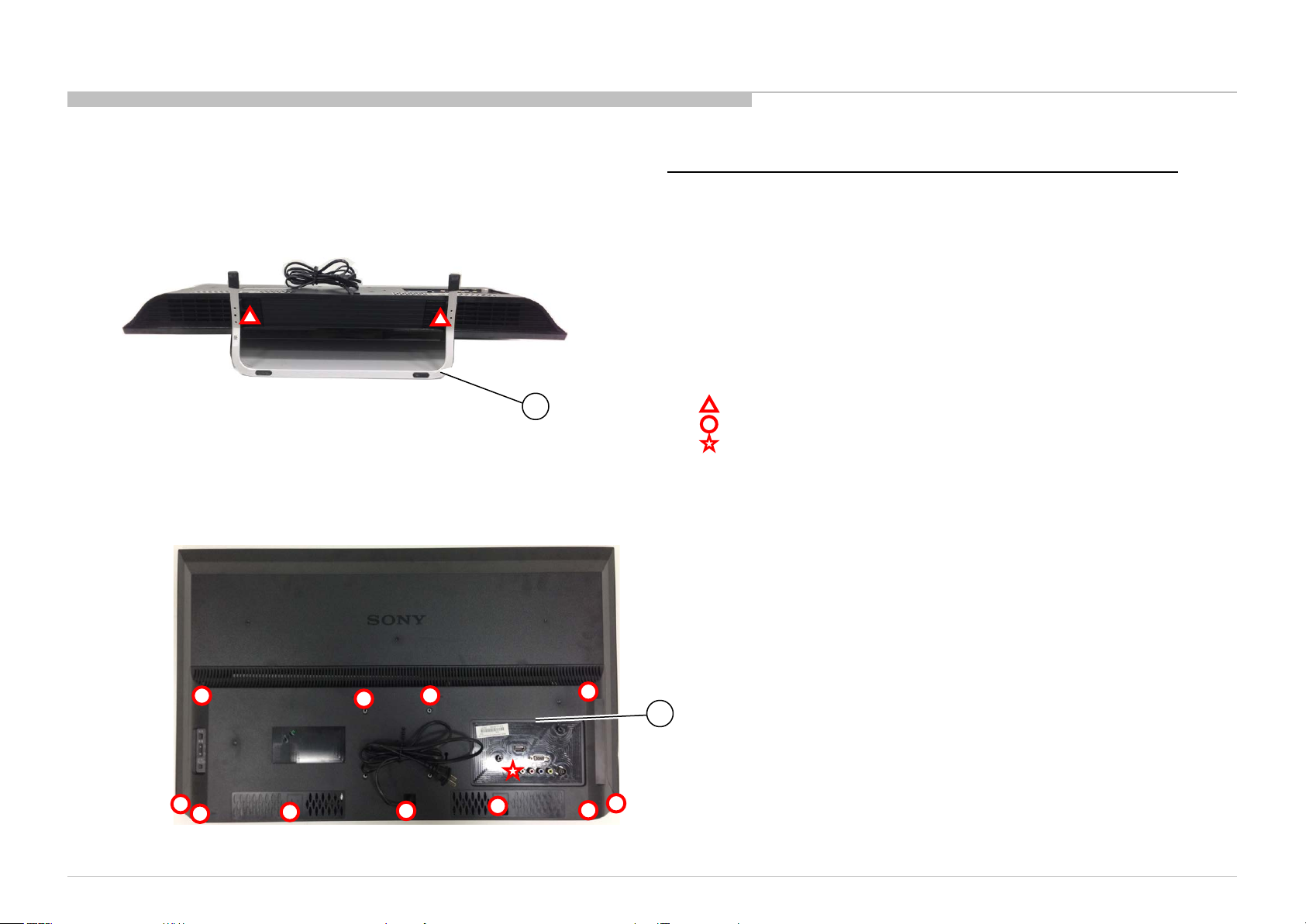
REF. No . PART No . DESCRIPTION MARK
3 1-492-329-21 SWITCH UNIT
4 1-910-108-04 FFC CABLE 32 MB-KEY 6P
5 1-858-888-21 LOUD SPEAKER (R) 40X100MM
6 1-474-486-11 GL3(ID)-STATIC CONVERTER(TV)
7 1-910-107-98 CONNECTOR ASSY 32 MB-SP LR 4P
8 1-846-662-11 POWER-SUPPLY CORD for KDL-32R420A/421A
/423A(AEP) /424A
1-846-663-11 POWER-SUPPLY CORD for K DL- 32R423A(UK )
9 1-910-108-02 FFC CABLE 32 MB- T CON 30P
10 1-910-108-03 FFC CABLE 32 MB- IR 10P
11 1-910-107-97 CONNECTOR A SSY 32 MB-PSU 14P
12 1-895-375-11 MOUNTED PWB A for K DL- 32R420A/ 421A
1-895-375-21 M O UNTED PWB A for K DL- 32R423A(AEP) /424A
1-895-375-31 M O UNTED PWB A for K DL- 32R423A(UK)
13 1-858-888-11 LOUD SPEA KER (L) 40X100MM
14 A-1939-532-A LCM ASSY (32FANFY MR) EU for K DL- 32R420A/ 423A
A-1939-533-A LCM ASSY (32FANFY HL) EU for K DL- 32R421A/ 424A
15 4-459-475-21 BRACKET, V ESA (FANF)
16 1-910-107-99 G ROUND CABLE 32 MB-PSU (M )
7-685-646-79 SCREW +BVT P 3X8 TYPE2 IT -3
1-1. KDL-32R420A/421A/423A/424A
1-1-3. GL3 BOARD, A BOARD, SPEAKER AND VESA BRACKET
DISASSEMBLY AND PARTS LIST
8
9
4
3
5
6
7
10
11
12
13
15
14
16
KDL-32R420A/421A/423A/424A , 40R470A/471A/473A/ 474A, 46R470A/473A(A EP/UK)
13
Page 14
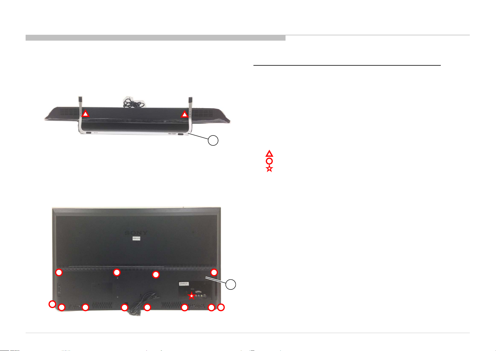
1-2. KDL-40R470A/471A/473A/474A
REF. No . PART No . DESCRIPTION MARK
1 4-446-635-01 STAND SHAFT (ML2)
2 4-459-446-51 COV E R, UNDER (40F ANF ) for KDL-40R473(UK )
4-459-446-61 COVER, UNDE R ( 40FA NF) for K DL- 40R470A/ 471A
/473(AEP ) /474A
2-580-608-11 SCREW, +PSW M 5X16
2-580-639-01 SCREW, +BV T P 4X12 TYPE2 IT-3
7-685-647-79 SCREW +BVT P 3X10 TYPE2 IT-3
1-2-1. STAND SHAFT
DISASSEMBLY AND PARTS LIST
1
1-2-2. COVER, UNDER
KDL-32R420A/421A/423A/424A , 40R470A/471A/473A/ 474A, 46R470A/473A(A EP/UK)
2
14
Page 15
REF. No . PART No . DESCRIPTION MARK
3 1-910-108-12 FFC CABLE 40 MB-KEY 6P
4 1-492-329-21 SWITCH UNIT
5 1-474-487-11 GL4(CH)-STAT I C CONV ERTER (TV)
6 1-858-888-21 LOUD SPEAKER (R) 40X100MM
7 1-910-108-06 CONNECTOR ASSY 40 MB-SP LR 4P
8 1-846-662-11 POWER-SUPPLY CORD for K DL- 40R470A/ 471A
/473A(AEP) /474A
1-846-663-11 POWER-SUPPLY CORD for K DL- 40R473A(UK )
9 1-910-108-10 FFC CABLE 40 MB- T CON 51P
10 1-910-108-05 CONNECTOR A SSY 40 MB-PSU 14P
11 1-910-108-11 FFC CABLE 40 MB- IR 10P
12 1-895-375-41 MOUNTED PWB A for K DL- 40R470A/ 471A
1-895-375-51 M O UNTED PWB A for K DL- 40R473A(AEP) /474A
1-895-375-61 M O UNTED PWB A for K DL- 40R473A(UK)
13 1-858-888-11 LOUD SPEA KER (L) 40X100MM
14 A-1939-535-A LCM ASSY (40FANFY MR) EU f or K DL- 40R470A/ 473A
A-1939-536-A LCM ASSY (40FANFY HL) EU for KDL-40R471A/474A
15 4-459-475-21 BRACKET, V ESA (FANF)
7-685-646-79 SCREW, +BV T P 3X8 TYPE2 IT -3
2-580-639-01 SCREW, +BV T P 4X12 TYPE2 IT-3
1-2. KDL-40R470A/471A/473A/474A
1-2-3. GL4 BOARD, A BOARD AND SPEAKER
DISASSEMBLY AND PARTS LIST
8
10
3
5
4
1-2-4. VESA BRACKET
6
7
15
9
11
14
12
13
15
KDL-32R420A/421A/423A/424A , 40R470A/471A/473A/ 474A, 46R470A/473A(A EP/UK)
15
Page 16
REF. No . PART No . DESCRIPTION MARK
1 4-446-636-01 STAND SHAFT (L2)
2 4-459-473-51 COV E R, UNDER (46F ANF ) for KDL- 46R473A(UK )
4-459-473-61 COVER, UNDE R ( 46FA NF) for K DL- 46R470A/ 473A(AEP )
2-580-608-11 SCREW, +PSW M 5X16
2-580-639-01 SCREW, +BV T P 4X12 TYPE2 IT-3
7-685-647-79 SCREW +BVT P 3X10 TYPE2 IT-3
1-3. KDL-46R470A/473A
1-3-1. STAND SHAFT
1-3-2. COVER, UNDER
DISASSEMBLY AND PARTS LIST
1
KDL-32R420A/421A/423A/424A , 40R470A/471A/473A/ 474A, 46R470A/473A(A EP/UK)
2
16
Page 17

REF. No . PART No . DESCRIPTION MARK
3 1-492-329-21 SWITCH UNIT
4 1-910-108-20 FFC CABLE 46 MB-KEY 6P
5 1-474-488-11 GL5(CH)-STAT I C CONV ERTER (TV)
6 1-858-888-21 LOUD SPEAKER (R) 40X100MM
7 1-910-108-14 CONNECTOR ASSY 46 MB-SP LR 4P
8 1-846-662-11 POWER-SUPPLY CORD for K DL- 46R470A/ 473A(AEP)
1-846-663-11 POWER-SUPPLY CORD for K DL-46R473A(UK )
9 1-910-108-18 FFC CABLE 46 MB- TCON 51P
10 1-910-108-19 FFC CABLE 46 MB- IR 10P
11 1-910-108-13 CONNECTOR A SSY 46 MB-PSU 14P
12 1-895-375-41 MOUNTED PWB A for K DL- 40R470A
1-895-375-51 M O UNTED PWB A for K DL- 46R473A(AEP)
1-895-375-61 M O UNTED PWB A for K DL- 46R473A(UK)
13 1-858-888-11 LOUD SPEA KER (L) 40X100MM
14 A-1939-537-A LCM ASSY (46FANFY MR) EU for KDL- 46R470A/473A
15 4-459-475-31 BRACKET, V ESA (FANF)
7-685-646-79 SCREW, +BV T P 3X8 TYPE2 IT -3
4-465-806-01 GEAR SCREW M 3X5 22
2-580-639-01 SCREW, +BV T P 4X12 TYPE2 IT-3
7-685-647-79 SCREW +BVT P 3X10 TYPE2 IT-3
1-3. KDL-46R470A/473A
1-3-3. GL5 BOARD, A BOARD AND SPEAKER
DISASSEMBLY AND PARTS LIST
14
8
4
5
3
1-3-4. VESA BRACKET
6
7
9
10
15
11
12
13
15
KDL-32R420A/421A/423A/424A , 40R470A/471A/473A/ 474A, 46R470A/473A(A EP/UK)
17
Page 18

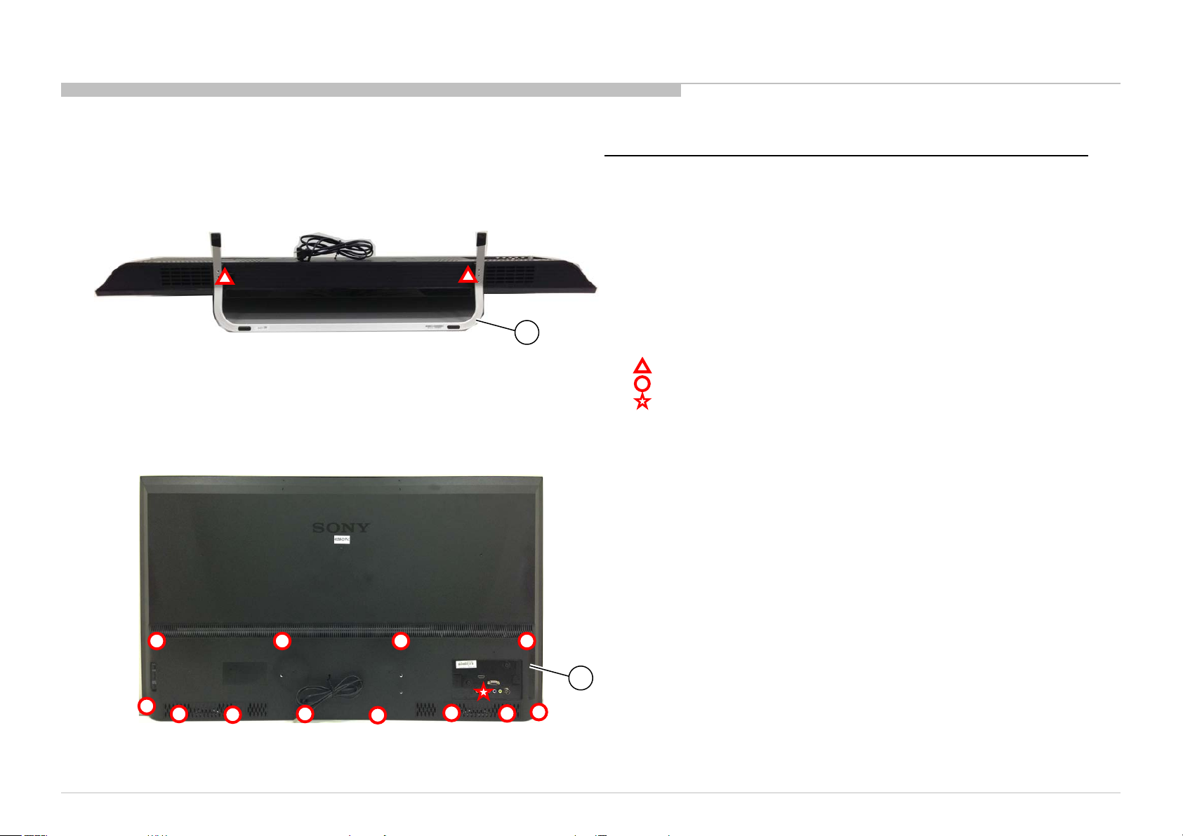
1-4. OTHER PART
PART No . DESCRIPTION MARK
1-492-067-11 REMOTE CO MMANDER (RM-E D054)
4-458-514-11 MA NUAL, INSTRUCTION GB
4-458-514-21 MA NUAL, INSTRUCTION FR/ES/NL/DE/PT
4-458-514-31 MA NUAL, INSTRUCTION NO/FI/DK/SE
4-458-514-41 MA NUAL, INSTRUCTION PL/HU/CZ/SK/RO/BG/GR/IT
4-458-514-91 MA NUAL, INSTRUCTION RU/UA
4-459-474-21 BRACKET, VESA T O P LO NG A (46FAN) for wall mount (46inch only)
2-580-602-01 SCREW, +PSW M4X12 (V ESA L FA N) for wall mount (46inc h only)
1-4-1. MISCELLANEOUS
DISASSEMBLY AND PARTS LIST
KDL-32R420A/421A/423A/424A , 40R470A/471A/473A/ 474A, 46R470A/473A(A EP/UK)
18
Page 19
SEC 2. ADJUSTMENT
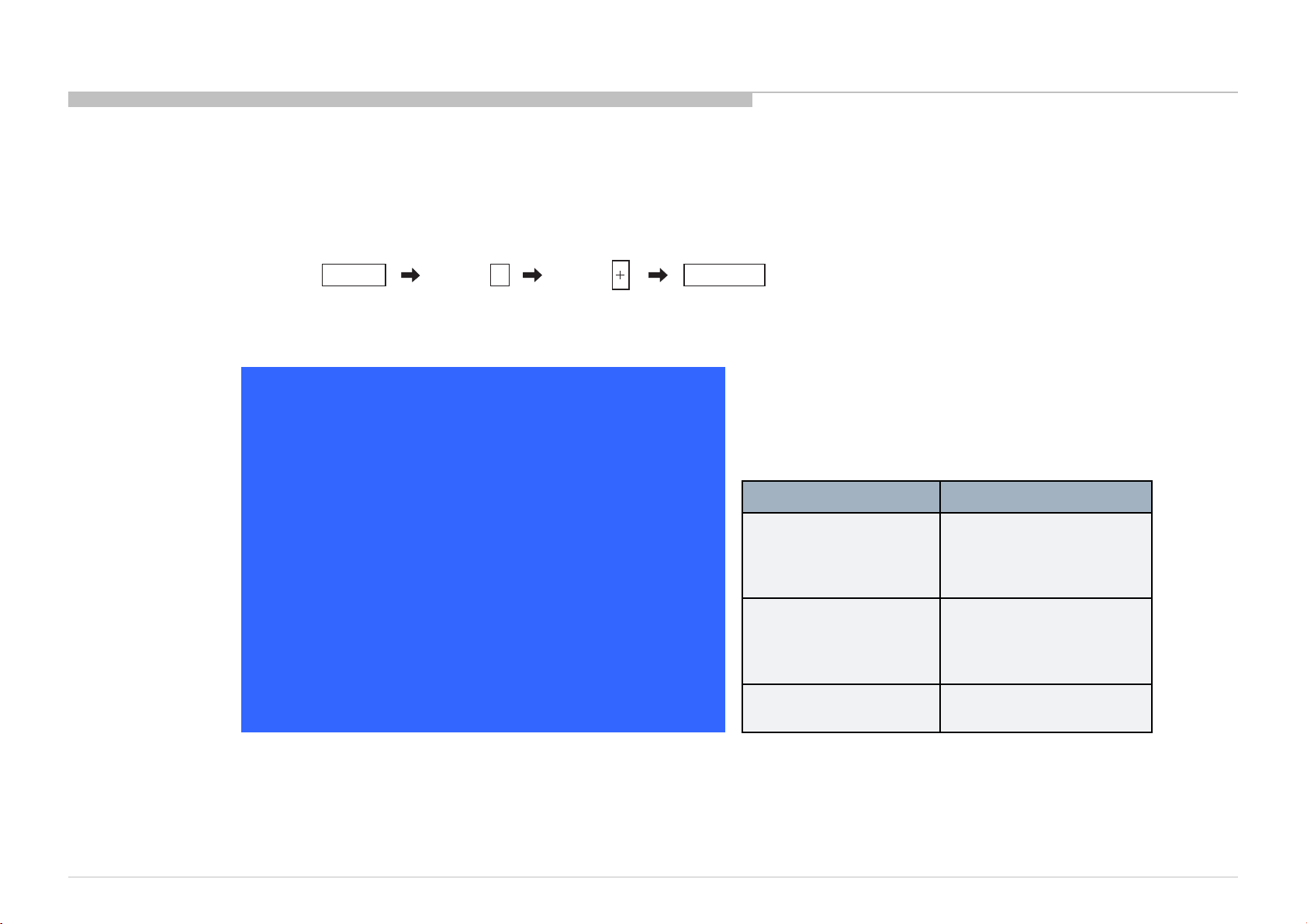
HOW TO ENTERING SERVICE MODE
1) Turn on the main power switch to place this set in standby mode.
2) Press the buttons on the remote commander as follows, and entering servi ce mode.
3) Service mode display.
Info TV POWERChannel Volume
Service Mode
Status Information >>
Self diagnosis history >>
Panel Selection <[ 19_S320DB3-1_EU ]>
NO_SIGNAL_MUTE <[ Off ]>
TUNING SYSTEM <[ AUTO ]>
LVDS Spectrum (%o) <[ 30 ]>
Low of HPD <[ 5 ]>
UART Selection <[ Usb Fact ]>
SERIAL NUMBER EDID 6000001
MODEL NAME EDID KDL-32R420A
5
[</>]Set[Home]Exit
Panel Selection MODEL NAME EDID
19_S320DB3-1_EU KDL-32R420A
KDL-32R421A
KDL-32R423A
KDL-32R424A
18_S400DH1-1_EU KDL-40R470A
KDL-40R471A
KDL-40R473A
KDL-40R474A
48_S460DH1-1_EU KDL-46R470A
KDL-46R473A
- When replace Main Board or panel, please confirm "Panel Selection" and "MODEL NAME EDID" in service mode.
If they are different, please select a suitable thing.
- Change of SERIAL NUMBER EDID and MODEL NAME EDID are possible only once when they are white character.
Note: About the software data update, please refer to “APPENDIX-4”.
KDL-32R420A/421A/423A/424A, 40R470A/471A/473A/474A, 46R470A/473A(AEP/UK)
19
Page 20
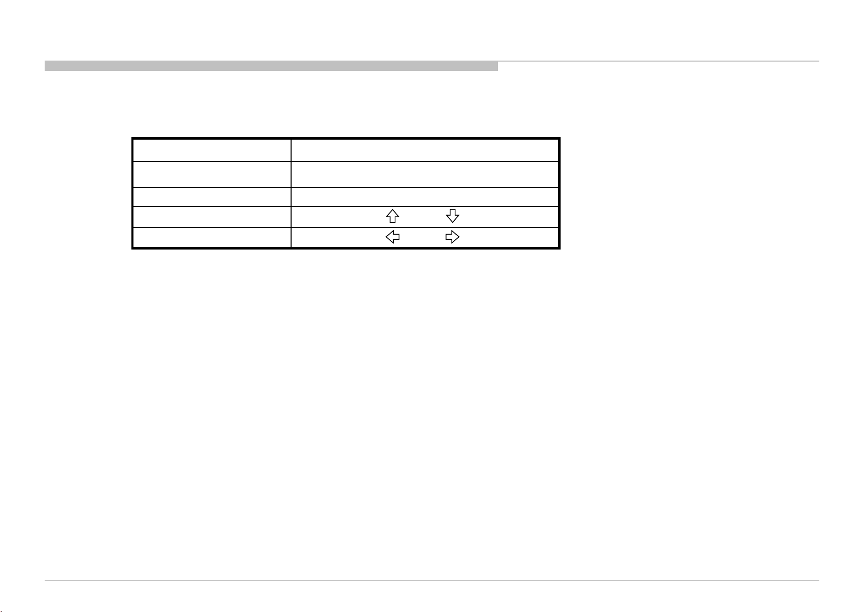
4) How to use the remote commander.
Function The flow of control
Service mode on <Info><5><Vol Up><Power>
Service mode off <Other> / <Power off + on>
Adjustment Item up / down /
Data Value up / down /
5) After entering service mode, then turn off the power switch.
ADJUSTMENT
KDL-32R420A/421A/423A/424A , 40R470A/471A/473A/ 474A, 46R470A/473A(A EP/UK)
20
Page 21
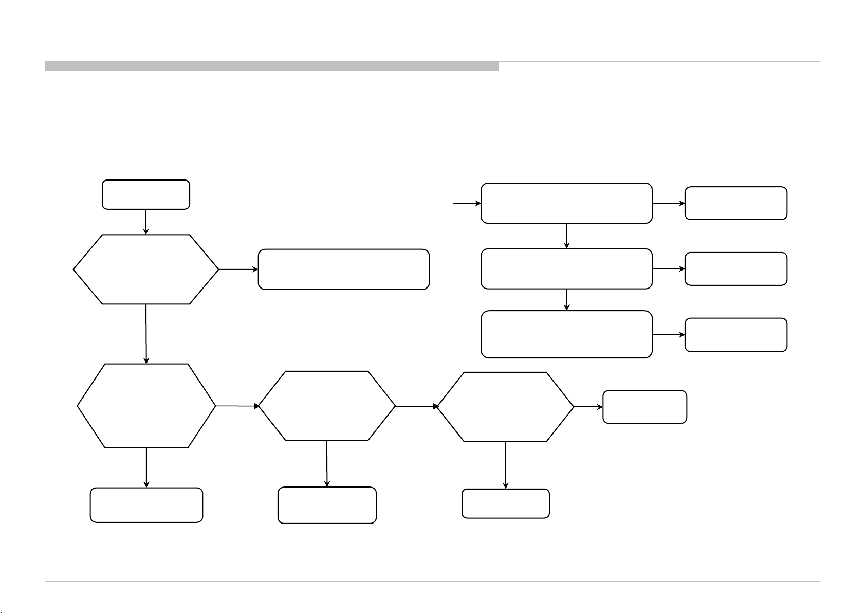
SEC 3. TROUBLE SHOOTING
3-1. NO POWER
No power
Long AC off(> 15 min.)
and then
Power On
NG
Check SB_3.3V
at 1 pin of CN201
on the Main board
Between 3.14~3.45V
OK
OK
NG
Enter Service Mode and check
Self diagnosis history
Check the harne ss
PSU to M/B
connection
NG
OK
IF MAIN_POWER > 0 or
DC_ALERT1 > 0
IF AUDIO_PROT > 0
BACKLIGHT_ERR > 0
Replace the harness
between PSU and
Main board
OK
Symptom
improvement
No
No
NG
Change
PSU
Yes
Yes
Yes
Change
Main board
Change
Main board
Change
Panel
Change
Main board
KDL-32R420A/421A/423A/424A , 40R470A/471A/473A/ 474A, 46R470A/473A(A EP/UK)
Fix the harness
connection
Harness issue
21
Page 22

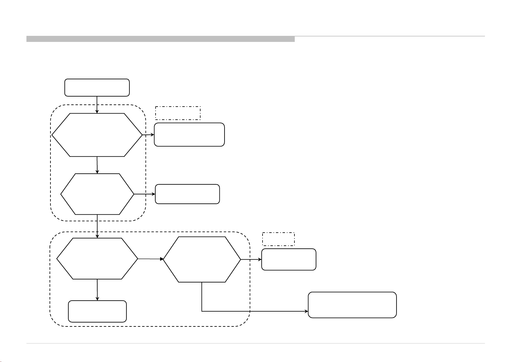
3-2. STANDBY LED BLINK
1) 2 times blinking (Main Power Error)
2-time blinking
TROUBLE SHOOTING
Check REG+12V at
CN201_Pin-3/8 on
NG
Main board
(11.8~13.2V)
OK
Change
Main board
KDL-32R420A/421A/423A/424A , 40R470A/471A/473A/ 474A, 46R470A/473A(A EP/UK)
Check PSU_EN# at
CN201_Pin-6 on
Main board
<2.6V
Change
Main board
>=2.6V
Check the harne ss
PSU to M/B
connection
NG
Fix the harness
connection
OK
Replace the harness
between PSU and
Main board
Symptom
OK
improvement
Harness issue
NG
Change
PSU
22
Page 23
2) 3 times blinking (Main Board Error)
3-time blinking
Check PWM_5V at
NG
L202 pin-2 on Main board
(4.75~5.25V)
OK
TROUBLE SHOOTING
DC_ALERT
U202, L202, etc
Change Main board
Check SYS_3.3V
at U204_Pin-6
on Main Board
NG
U204, etc
Change Main board
(3.135~3.465V)
OK
Check the harne ss
M/B to Speaker
connection
NG
OK
Check the speaker
Impedance at the
SP Connector
(8ohm+/-15%)
OK
Fix the harness
connection
KDL-32R420A/421A/423A/424A , 40R470A/471A/473A/ 474A, 46R470A/473A(A EP/UK)
AUDIO
NG
Change Speaker
Demo, Audio, Tuner, etc
Change Main board
23
Page 24

3) 6 times blinking (Backlight Erro r)
6-time blinking
TROUBLE SHOOTING
Check PSU_B L_EN #
at CN201_Pin-14
on the Main board
>=2.4V
Check PSU_BL_ERR#
at CN201_Pin-13
on the Main board
>=1.8V
Check the harne ss
PSU to M/B
connection
OK
Replace the harness
PSU to Main board
<2.4V
<=0.7V
NG
Symptom
improvement
OK
Change
Main board
Change
Main board
Fix the harness
connection
Harness issue
Check the FFC(LV DS)
Between
PSU and Panel
connection
OK
Replace the
FFC(LVDS) Between
PSU and Panel
NG
Replace PSU
NG
Change
Panel
NG
Fix the FFC(LVDS)
connection
OK
OK
FFC(LVDS)
issue
PSU issue
NG
KDL-32R420A/421A/423A/424A , 40R470A/471A/473A/ 474A, 46R470A/473A(A EP/UK)
24
Page 25

3-3. NO PICTURE
No picture
TROUBLE SHOOTING
Press HOME Key.
Menu displayed?
Yes
Change Equipment
Or Player to check
TV display
OK
Signal or Equipment
Problem
No
No display
Check the harne ss
PSU to Panel
connection
NG
Fix the harness
connection
Change
Main board
OK
Replace
PSU to Panel
Harness
Symptom
OK
improvement
Harness issue
NG
Check the FFC(LV DS)
Fix the FFC(LVDS)
Change PSU
Symptom
OK
improvement
PSU issue
PSU to Panel
connection
NG
connection
NG
OK
Replace the
FFC(LVDS) Between
PSU and Panel
OK
FFC(LVDS) issue
Change
Panel
NG
Change
Main board
OK
Main board issue
NG
KDL-32R420A/421A/423A/424A , 40R470A/471A/473A/ 474A, 46R470A/473A(A EP/UK)
25
Page 26

3-4. NO SOUND
No Sound
TROUBLE SHOOTING
Check if TV is
set to Mute
No
Check the
“Speakers setting”
“TV Speakers”
Change the speaker
harness
OK
Symptom
improvement
Speaker Harness
issue
Yes
“Audio System”
NG
Change to
Un-mute
Change to
“TV Speaker”
Replace
Main board
NG
Change
Speaker
Symptom
improvement
Main board issue
OK
KDL-32R420A/421A/423A/424A , 40R470A/471A/473A/ 474A, 46R470A/473A(A EP/UK)
26
Page 27

3-5. TV COMMANDER BUTTONS MALFUNCTION
1) TV button malfunction
Button malfunction
on the TV
TROUBLE SHOOTING
Replace the harness
between Main board
and Key module
Symptom
OK
improvement
Harness issue
NG
Change
Key module
NG
Change
Main board
Symptom
improvement
Key module issue
OK
KDL-32R420A/421A/423A/424A , 40R470A/471A/473A/ 474A, 46R470A/473A(A EP/UK)
27
Page 28

2) IR remote commander malfunction
TV isn’t controlled
by remote commander
TROUBLE SHOOTING
Green LED li ght
at power indicator
OK
Green LED blinks at power indicator
when using commander
near sensor’s windo w
NG
Symptom
Change Main board to
IR board FFC
improvement
OK
IR FFC
issue
NG
Symptom
improvement
Change IR board IR board issue
OK
NG
Change
Main board
NG
OK
Change
Remote Control
battery
KDL-32R420A/421A/423A/424A , 40R470A/471A/473A/ 474A, 46R470A/473A(A EP/UK)
28
Page 29

SEC 4. DIAGRAMS
4-1. BLOCK DIAGRAM
KDL-32R420A/421A/423A/424A , 40R470A/471A/473A/ 474A, 46R470A/473A(A EP/UK)
29
Page 30

4-2. CONNECTOR DIAGRAM
DIAGRAMS
Panel
Key Pad
CN6401
Power Board
Speaker
GROUND
CABLE (32)
T-Con Board
IR Board
CN4001(32)
CN4002(40/46)
CN8001
CN4006
CN4003
CN950
CN201
Main Board
Speaker
KDL-32R420A/421A/423A/424A , 40R470A/471A/473A/ 474A, 46R470A/473A(A EP/UK)
30
Page 31

4-3. CIRCUIT BOARDS LOCATION
DIAGRAMS
Switch Unit
KDL-32R420A/421A/423A/424A
GL3 Board
KDL-46R470A/473A
A Board
H Board
Switch Unit
KDL-40R470A/471A/473A/474A
GL4 Board
A Board
H Board
GL5 Board
Switch Unit
KDL-32R420A/421A/423A/424A , 40R470A/471A/473A/ 474A, 46R470A/473A(A EP/UK)
A Board
H Board
31
Page 32

END
Home Entertainment &Sound
9-888-532-02
KDL-32R420A/421A/423A/424A, 40R470A/471A/473A/474A, 46R470A/473A(AEP/UK)
Sony Corporation
Business Group
English
2013CL08-Data
Made in Japan
© 2013. 03
32
Page 33

APPENDIX-1
WIRE DRESSING
1. KDL-32R420A/421A/423A/424A
Keypad wire dressing
KDL-32R420A/421A/423A/424A , 40R470A/471A/473A/ 474A, 46R470A/473A(A EP/UK)
33
Page 34

1. KDL-32R420A/421A/423A/424A
PSU->MB dressing-1
APPENDIX-1
KDL-32R420A/421A/423A/424A , 40R470A/471A/473A/ 474A, 46R470A/473A(A EP/UK)
34
Page 35

1. KDL-32R420A/421A/423A/424A
PSU->MB dressing-2
Dress the cloth tape as
showed area.
Align the harness black
tape.
0~3mm.
APPENDIX-1
Part Name: ACETATE CLOTH TAPE W10
Part Number: 4-468-753-01
Part Name: ACETATE CLOTH TAPE W20
Part Number: 4-468-753-11
KDL-32R420A/421A/423A/424A , 40R470A/471A/473A/ 474A, 46R470A/473A(A EP/UK)
35
Page 36

1. KDL-32R420A/421A/423A/424A
Speaker and GND combine dressing-1
APPENDIX-1
KDL-32R420A/421A/423A/424A , 40R470A/471A/473A/ 474A, 46R470A/473A(A EP/UK)
36
Page 37

1. KDL-32R420A/421A/423A/424A
Speaker and GND combine dressing-2
APPENDIX-1
KDL-32R420A/421A/423A/424A , 40R470A/471A/473A/ 474A, 46R470A/473A(A EP/UK)
37
Page 38

1. KDL-32R420A/421A/423A/424A
Speaker and GND combine dressing-3
APPENDIX-1
KDL-32R420A/421A/423A/424A , 40R470A/471A/473A/ 474A, 46R470A/473A(A EP/UK)
38
Page 39

1. KDL-32R420A/421A/423A/424A
Speaker and GND combine dressing-4
APPENDIX-1
NG
OK
Note:
Speaker & Ground wire combined harness need keep
away with S-board, speaker harness keep close to
Speaker Baffle i nside of gr ound harness .
KDL-32R420A/421A/423A/424A , 40R470A/471A/473A/ 474A, 46R470A/473A(A EP/UK)
NG
39
Page 40

1. KDL-32R420A/421A/423A/424A
IR dressing
APPENDIX-1
KDL-32R420A/421A/423A/424A , 40R470A/471A/473A/ 474A, 46R470A/473A(A EP/UK)
40
Page 41

1. KDL-32R420A/421A/423A/424A
LVDS dressing
APPENDIX-1
KDL-32R420A/421A/423A/424A , 40R470A/471A/473A/ 474A, 46R470A/473A(A EP/UK)
41
Page 42

1. KDL-32R420A/421A/423A/424A
GND dressing
APPENDIX-1
KDL-32R420A/421A/423A/424A , 40R470A/471A/473A/ 474A, 46R470A/473A(A EP/UK)
42
Page 43

1. KDL-32R420A/421A/423A/424A
AC dressing
APPENDIX-1
KDL-32R420A/421A/423A/424A , 40R470A/471A/473A/ 474A, 46R470A/473A(A EP/UK)
Note:
AC CORE must dressed hor izontally, at
the FFC harness top.
43
Page 44

1. KDL-32R420A/421A/423A/424A
Overview
APPENDIX-1
KDL-32R420A/421A/423A/424A , 40R470A/471A/473A/ 474A, 46R470A/473A(A EP/UK)
44
Page 45

2. KDL-40R470A/471A/473A/474A
Keypad wire dressing-1
APPENDIX-1
KDL-32R420A/421A/423A/424A , 40R470A/471A/473A/ 474A, 46R470A/473A(A EP/UK)
45
Page 46

2. KDL-40R470A/471A/473A/474A
Keypad wire dressing-2
APPENDIX-1
KDL-32R420A/421A/423A/424A , 40R470A/471A/473A/ 474A, 46R470A/473A(A EP/UK)
46
Page 47

2. KDL-40R470A/471A/473A/474A
PSU->MB dressing
APPENDIX-1
KDL-32R420A/421A/423A/424A , 40R470A/471A/473A/ 474A, 46R470A/473A(A EP/UK)
47
Page 48

2. KDL-40R470A/471A/473A/474A
Speaker and GND combine dressing-1
APPENDIX-1
KDL-32R420A/421A/423A/424A , 40R470A/471A/473A/ 474A, 46R470A/473A(A EP/UK)
48
Page 49

2. KDL-40R470A/471A/473A/474A
Speaker and GND combine dressing-2
APPENDIX-1
KDL-32R420A/421A/423A/424A , 40R470A/471A/473A/ 474A, 46R470A/473A(A EP/UK)
49
Page 50

2. KDL-40R470A/471A/473A/474A
Speaker and GND combine dressing-3
APPENDIX-1
KDL-32R420A/421A/423A/424A , 40R470A/471A/473A/ 474A, 46R470A/473A(A EP/UK)
50
Page 51

2. KDL-40R470A/471A/473A/474A
IR dressing
APPENDIX-1
KDL-32R420A/421A/423A/424A , 40R470A/471A/473A/ 474A, 46R470A/473A(A EP/UK)
51
Page 52

2. KDL-40R470A/471A/473A/474A
LVDS dressing
APPENDIX-1
KDL-32R420A/421A/423A/424A , 40R470A/471A/473A/ 474A, 46R470A/473A(A EP/UK)
52
Page 53

2. KDL-40R470A/471A/473A/474A
AC dressing
Part Name: ACETATE CLOTH TAPE W20
Part Number: 4-468-753-11
APPENDIX-1
KDL-32R420A/421A/423A/424A , 40R470A/471A/473A/ 474A, 46R470A/473A(A EP/UK)
53
Page 54

2. KDL-40R470A/471A/473A/474A
Overview
APPENDIX-1
KDL-32R420A/421A/423A/424A , 40R470A/471A/473A/ 474A, 46R470A/473A(A EP/UK)
54
Page 55

3. KDL-46R470A/473A
Keypad wire dressing-1
APPENDIX-1
KDL-32R420A/421A/423A/424A , 40R470A/471A/473A/ 474A, 46R470A/473A(A EP/UK)
55
Page 56

3. KDL-46R470A/473A
Keypad wire dressing-2
APPENDIX-1
KDL-32R420A/421A/423A/424A , 40R470A/471A/473A/ 474A, 46R470A/473A(A EP/UK)
56
Page 57

3. KDL-46R470A/473A
PSU->MB dressing-1
APPENDIX-1
KDL-32R420A/421A/423A/424A , 40R470A/471A/473A/ 474A, 46R470A/473A(A EP/UK)
57
Page 58

3. KDL-46R470A/473A
Speaker and GND combine dressing-1
APPENDIX-1
KDL-32R420A/421A/423A/424A , 40R470A/471A/473A/ 474A, 46R470A/473A(A EP/UK)
58
Page 59

3. KDL-46R470A/473A
Speaker and GND combine dressing-2
APPENDIX-1
KDL-32R420A/421A/423A/424A , 40R470A/471A/473A/ 474A, 46R470A/473A(A EP/UK)
59
Page 60

3. KDL-46R470A/473A
Speaker and GND combine dressing-3
APPENDIX-1
KDL-32R420A/421A/423A/424A , 40R470A/471A/473A/ 474A, 46R470A/473A(A EP/UK)
60
Page 61

3. KDL-46R470A/473A
IR dressing
APPENDIX-1
KDL-32R420A/421A/423A/424A , 40R470A/471A/473A/ 474A, 46R470A/473A(A EP/UK)
61
Page 62

3. KDL-46R470A/473A
LVDS dressing
APPENDIX-1
KDL-32R420A/421A/423A/424A , 40R470A/471A/473A/ 474A, 46R470A/473A(A EP/UK)
62
Page 63

3. KDL-46R470A/473A
AC dressing
APPENDIX-1
KDL-32R420A/421A/423A/424A , 40R470A/471A/473A/ 474A, 46R470A/473A(A EP/UK)
63
Page 64

3. KDL-46R470A/473A
Overview
APPENDIX-1
KDL-32R420A/421A/423A/424A , 40R470A/471A/473A/ 474A, 46R470A/473A(A EP/UK)
Part Name: HIMELON (FANF)
Part Number: 4-466-473-61
Part Name: ACETATE CLOTH TAPE W20
Part Number: 4-468-753-11
64
Page 65

APPENDIX-2
TAPE POSITION
1. KDL-32R420A/421A/423A/424A
Must cover the plastic cover area
0~2 mm
SPK baffle edge
0~2 mm
SPK edge
Part Name: HIMELON (FANF)
Part Number: 4-466-473-41
KDL-32R420A/421A/423A/424A , 40R470A/471A/473A/ 474A, 46R470A/473A(A EP/UK)
Part Name: TAPE GASKET (FANF)
Part Number: 4-468-429-01
Gap: Label & Sponge
1 mm or less
0~1 mm
Part Name: CUSHION (FANF)
Part Number: 4-468-430-01
65
Page 66

1. KDL-32R420A/421A/423A/424A
285 mm ±4
APPENDIX-2
70 mm ±4
80 mm ±4
260 mm ±4
Paste 1 pcs tape on Vesa Bracket BTM picture red
mark area
Part Name: HEMELON (FANF)
Part Number: 4-466-473-01
KDL-32R420A/421A/423A/424A , 40R470A/471A/473A/ 474A, 46R470A/473A(A EP/UK)
NWF must apply cover the
CORE top side
Part Name: HEMELON (FANF)
Part Number: 4-466-473-71
0~1 mm
NWF must apply under
the SPK core
Part Name: HEMELON (FANF)
Part Number: 4-466-473-61
66
Page 67

1. KDL-32R420A/421A/423A/424A
APPENDIX-2
0~1 mm
0~5 mm
0~5 mm
Part Name: CUSHION (FANF)
Part Number: 4-468-430-01
Part Name: HIMELON (FANF)
Part Number: 4-466-473-51
KDL-32R420A/421A/423A/424A , 40R470A/471A/473A/ 474A, 46R470A/473A(A EP/UK)
CORE
TAPE GASKET(FANF)
RC
TAPE GASKET(FANF) MUST UNDER CORE
67
Page 68

1. KDL-32R420A/421A/423A/424A
APPENDIX-2
Align the line at PSU, can not
over line to bottom
0~3mm
KDL-32R420A/421A/423A/424A , 40R470A/471A/473A/ 474A, 46R470A/473A(A EP/UK)
Part Name: CUSHION (FANF)
Part Number: 4-468-430-01
68
Page 69

2. KDL-40R470A/471A/473A/474A
APPENDIX-2
Can not over METAL EDGE
0~5 mm
0~5 mm
Part Name: HIMELON (FANF)
Part Number: 4-466-473-51
KDL-32R420A/421A/423A/424A , 40R470A/471A/473A/ 474A, 46R470A/473A(A EP/UK)
0~2 mm
Check no peel off
Part Name: CUSHION, RUBBER (FANF)
Part Number: 4-467-119-21
0~2 mm
New must stick on the
EMI core top side
Part Name: HIMELON (FANF)
Part Number: 4-466-473-61
69
Page 70

2. KDL-40R470A/471A/473A/474A
APPENDIX-2
Part Name: HIMELON (FANF)
Part Number: 4-466-473-01
KDL-32R420A/421A/423A/424A , 40R470A/471A/473A/ 474A, 46R470A/473A(A EP/UK)
0~1 mm
NWF must apply under
the SPK core
Part Name: HIMELON (FANF)
Part Number: 4-466-473-71
Gap: Label & Sponge
1 mm or less
0~1 mm
Part Name: CUSHION (FANF)
Part Number: 4-468-430-01
70
Page 71

3. KDL-46R470A/473A
APPENDIX-2
3~6 mm
-1~1 mm
Part Name: HIMELON(FANF)
Part Number: 4-466-473-41
KDL-32R420A/421A/423A/424A , 40R470A/471A/473A/ 474A, 46R470A/473A(A EP/UK)
Can not hide the
screw hole
Part Name: HIMELON (FANF)
Part Number: 4-466-473-01
New must stick on the EMI
core top side
Part Name: HIMELON (FANF)
Part Number: 4-466-473-61
71
Page 72

3. KDL-46R470A/473A
APPENDIX-2
Gap: Label & Sponge
1 mm or less
NG
0~5 mm
0~5 mm
Assy. Speaker should be
pushed to flat
Part Name: HIMELON (FANF)
Part Number: 4-466-473-51
KDL-32R420A/421A/423A/424A , 40R470A/471A/473A/ 474A, 46R470A/473A(A EP/UK)
NG OK
OK
Speaker cable can’t be
clamped by bracket
0~1 mm
Part Name: CUSHION (FANF)
Part Number: 4-468-430-01
72
Page 73

4. SMALL PARTS LIST
KDL-32R420A/421A/423A/424A
Part name Part number T (mm) W (mm) L (mm) Qty/Set Primary part ( Adherence)
HIMELON (F ANF ) 4-466-473-41 0.7 8 110 2 SPEAKER
TAPE GA SKET (F ANF) 4-468-429-01 10 35 1 ESD BKT
CUSHI ON (FANF) 4-468-430-01 1 8 20 2 MB TUNER/ LE D CORE
HIMELON (F ANF ) 4-466-473-01 0.25 8 25 1 V ESA BKT
HIMELON (F ANF ) 4-466-473-61 0.5 8 25 1 A C CORE
HIMELON (F ANF ) 4-466-473-51 0.4 8 70 2 SIDE KEY
CUSHI ON (FANF) 4-468-430-11 6 8 20 1 PSU
HIMELON (F ANF ) 4-466-473-71 0.4 8 20 1 SPEAKER CORE
KDL-40R470A/471A/473A/474A
Part name Part number T (mm) W (mm) L (mm) Qty/Set Primary part ( Adherence)
CUSHI ON, RUBB E R ( FANF) 4-467-119-21 5 20 50 2 SPEAKER
CUSHI ON (FANF) 4-468-430-01 1 8 20 1 MB TUNER
HIMELON (F ANF ) 4-466-473-01 0.25 8 25 1 V ESA BKT
HIMELON (F ANF ) 4-466-473-51 0.4 8 70 2 SIDE KEY
HIMELON (F ANF ) 4-466-473-61 0.5 8 25 1 A C CORE
HIMELON (F ANF ) 4-466-473-71 0.4 8 20 1 SPEAKER CORE
KDL-46R470A/473A
Part name Part number T (mm) W (mm) L (mm) Qty/Set Primary part ( Adherence)
HIMELON (F ANF ) 4-466-473-41 0.7 8 110 2 SPEAKER
CUSHI ON (FANF) 4-468-430-01 1 8 20 1 MB TUNER
HIMELON (F ANF ) 4-466-473-01 0.25 8 25 1 V ESA BKT
HIMELON (F ANF ) 4-466-473-51 0.4 8 70 2 SIDE KEY
HIMELON (F ANF ) 4-466-473-61 0.5 8 25 1 A C CORE
COMMON
Part name Part number T (mm) W (mm) L (mm) Qty/Set Primary part ( Adherence)
ACETATE CLOTH TAPE W10 4-468-753-01 10 1
ACETATE CLOTH TAPE W20 4-468-753-11 20 1
APPENDIX-2
KDL-32R420A/421A/423A/424A , 40R470A/471A/473A/ 474A, 46R470A/473A(A EP/UK)
73
Page 74

APPENDIX-3
SWITCH UNIT DISASSEMBLY
KDL-32R420A/421A/423A/424A , 40R470A/471A/473A/ 474A, 46R470A/473A(A EP/UK)
74
Page 75

APPENDIX-4
SOFTWARE DATA UPDATE
THE CONFIRMATION OF THE SOFTWARE VERSION OF THE TV SET
Entering product information of setting menu.
Please use the latest s oft ware.
1: KDL-xxRxxxx
2: xxxxxxx
[HOME] - [Settings] - [Set-up] - [Product Informatio n]
SOFTWARE DOWNLOAD
The downloaded software may be compressed(.zip).
If the downloaded software was compressed(.zip), please unzip it.
Store the software package to USB memory. (Applicable USB memory : Format by FAT32, USB2.0 type )
However, please store only the following one file to USB memory for software update.
BA (EU) : sony_fw_2013_xxxx_AEUF1.pkg
3: vx.xxx
Note: When changing Main board, Model Name and Serial Number will not be
displayed.
1. Model Name
2. Serial Number
3. Software Version
KDL-32R420A/421A/423A/424A , 40R470A/471A/473A/ 474A, 46R470A/473A(A EP/UK)
75
Page 76

SOFTWA RE UPDATE BY USB MEMORY
1. Turn on the TV.
2. Unplug the AC power code.
3. Connect the USB memory.
APPENDIX-4
Starting update
Lights up Red LED and Orange LED is flashing. (1-2min)
Note: Do not connect USB memory i n s tandby mode.
4. Plug the AC power cord then update starts automatically.
Lights up Green LED. (no picture)
KDL-32R420A/421A/423A/424A , 40R470A/471A/473A/ 474A, 46R470A/473A(A EP/UK)
Finish update
Lights up Green LED again and TV is turned on.
5. Unplug AC power cord and disconnect USB memory.
6. Plug the AC power cord then turn on the TV.
CONFIRM SOFTWARE VERSION
Please confirm whether it is the latest software.
Product information of setting menu.
[HOME] - [Settings] - [Set-up] - [Product Information]
76
 Loading...