

Page 1

SERVICE MANUAL
*Table of contents is on the last page. Please also utilize "Bookmarks“ function / "Find" function on Acrobat PDF data.
XE85 Series
ORIGINAL MANUAL ISSUE DATE: 3/2017
SI2C013500 - 1/5/2022 12:13 PM
Version Date Subject
1.0 3/2017 Original manual issue.
GN3TR CHASSIS
KH Segment
LCD TV
9-888-821-01
Page 2

MODEL LIST
MODEL COLOR COMMANDER DEST.
KD-55XE8505 Black RMF-TX300E CEI/UKA
KD-55XE8577 Silver RMF-TX300E UKA/RU3
RMF-TX301E CEI
KD-55XE8588 Black RMF-TX201ES CEI
KD-55XE8596 Black RMF-TX300E CEI/UKA/RU3
KD-55XE8599 Black RMF-TX201ES CEI
KD-65XE8505 Black RMF-TX300E CEI/UKA
KD-65XE8577 Silver RMF-TX300E UKA/RU3
RMF-TX301E CEI
KD-65XE8588 Black RMF-TX201ES CEI
KD-65XE8596 Black RMF-TX300E CEI/UKA/RU3
KD-65XE8599 Black RMF-TX201ES CEI
FW-65XE8501 Black RMF-TX300E CEI/UKA
RMT-TX210E
MODEL COLOR COMMANDER DEST.
KD-75XE8596 Black RMF-TX300E CEI/UKA/RU3
FW-75XE8501 Black RMF-TX300E CEI/UKA
RMT-TX210E
KD-55/65/75XE8505,8577,8588,8596,8599,FW-65/75XE8501
2
Page 3

WARNINGS AND CAUTIONS - ENGLISH
CAUTION
These servicing instructions are for use by qualified service personnel only.
To reduce the risk of electric shock, do not perform any servicing other than that contained in the operating instructions unless you are qualified to do so.
WARNING!!
An isolation transformer should be used during any service to avoid possible shock hazard, because of live chassis.
The chassis of this receiver is directly connected to the ac power line.
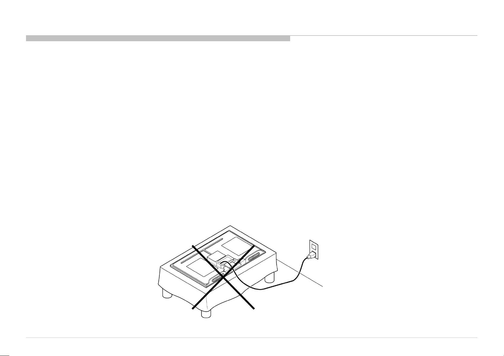
CARRYING THE TV
Be sure to follow these guidelines to protect your property and avoid causing serious injury.
SI2C013500 - 1/5/2022 12:13 PM
• Carry the TV with an adequate number of people; larger size TVs require two or more people.
• Correct hand placement while carrying the TV is very important for safety and to avoid damages.
SAFETY-RELATED COMPONENT WARNING!!
Components identified by shading and ! mark on the schematic diagrams, exploded views, and in the parts list are critical for safe operation. Replace these components with Sony
parts whose part numbers appear as shown in this manual or in supplements published by Sony. Circuit adjustments that are critical for safe operation are identified in this manual.
Follow these procedures whenever critical components are replaced or improper operation is suspected.
CAUTION ABOUT THE LITHIUM BATTERY
• Danger of explosion if battery is incorrectly replaced. Replace only with the same or equivalent type.
• Outer case broken battery should not contact to water.
IMPORTANT REMINDER FOR TV MAINBOARD REPLACEMENT
It is mandatory for service centers to confirm the TV's system information after each repair carried out with Mainboard replacement.
Whenever a TV Mainboard is replaced, the correct TV Model and Serial number must be reinserted into memory.
This is a MANDATORY procedure that each service center must apply.
Please refer to the chapter of ADJUSTMENT in this service manual to find out how to set the model number and serial number in service mode.
KD-55/65/75XE8505,8577,8588,8596,8599,FW-65/75XE8501
3
Page 4

WARNINGS AND CAUTIONS - FRENCH
ATTENTION!!
Ces instructions de service sont à l’usage du personnel de service qualifi é seulement.
Pour prévenir le risque de choc électrique, ne pas faire l’entretien autre que celui contenu dans le Mode d’emploi à moins que vous soyez qualifi é faire ainsi.
WARNING!!
Afi n d’eviter tout risque d’electrocution provenant d’un chássis sous tension, un transformateur d’isolement doit etre utilisé lors de tout dépannage. Le chássis de ce récepteur est
directement raccordé à l’alimentation du secteur.
POUR TRANSPORTER LE TÉLÉVISEUR
Tenez compte de ce qui suit pendant l’installation du téléviseur :
• Débranchez tous les câbles avant de transporter le téléviseur.
• Transportez le téléviseur avec le nombre de personnes approprié ; un téléviseur de grande taille doit être transporté par au moins deux personnes.
• Lors du transport du téléviseur, l’emplacement des mains est très important pour votre sécurité, ainsi que pour éviter de causer des dommages.
ALERTE!!
Afi n d’eviter tout risque d’electrocution provenant d’un chassis sous tension, un transformateur d’isolement doit etre utilise lors de tout depannage. Le chassis de ce recepteur est
directement raccorde a l’alimentation du secteur.
ATTENTION AUX COMPOSANTS RELATIFS A LA SECURITE!!
Les composants identifi es par une trame et par une marque sur les schemas de principe, les vues explosees et les listes de pieces sont d’une importance critique pour la securite
du fonctionnement. Ne les remplacer que par des composants Sony dont le numero de piece est indique dans le present manuel ou dans des supplements publies par Sony. Les
reglages de circuit dont l’importance est critique pour la securite du fonctionnement sont identifi es dans le present manuel. Suivre ces procedures lors de chaque remplacement de
composants critiques, ou lorsqu’un mauvais fonctionnement suspecte.
KD-55/65/75XE8505,8577,8588,8596,8599,FW-65/75XE8501
4
Page 5
USE CAUTION WHEN HANDLING THE LCD PANEL
When repairing the LCD panel, be sure you are grounded by using a wrist band.
When repairing the LCD panel on the wall, the LCD panel must be secured using the 4 mounting holes on the rear cover.
1) Do not press on the panel or frame edge to avoid the risk of electric shock.
2) Do not scratch or press on the panel with any sharp objects.
3) Do not leave the module in high temperatures or in areas of high humidity for an extended period of time.
4) Do not expose the LCD panel to direct sunlight.
5) Avoid contact with water. It may cause a short circuit within the module.
6) Disconnect the AC power when replacing the backlight (CCFL) or inverter circuit. (High voltage occurs at the inverter circuit at 650Vrms.)
7) Always clean the LCD panel with a soft cloth material.
8) Use care when handling the wires or connectors of the inverter circuit. Damaging the wires may cause a short.
9) Protect the panel from ESD to avoid damaging the electronic circuit (C-MOS).
10) It is recommended not to exceed 1 hour of Power-On nor Burn-in period with LCD panel face down condition, in repair activity.
WARNINGS AND CAUTIONS
KD-55/65/75XE8505,8577,8588,8596,8599,FW-65/75XE8501
5
Page 6

SAFETY CHECK-OUT
After correcting the original service problem, perform the following safety checks before releasing the set to the customer:
1. Check the area of your repair for unsoldered or poorly soldered connections. Check the entire board surface for solder splashes and bridges.
2. Check the interboard wiring to ensure that no wires are “pinched” or touching high-wattage resistors.
3. Check that all control knobs, shields, covers, ground straps, and mounting hardware have been replaced. Be absolutely certain that you have replaced all the insulators.
4. Look for unauthorized replacement parts, particularly transistors, that were installed during a previous repair. Point them out to the customer and recommend their replacement.
5. Look for parts which, though functioning, show obvious signs of deterioration. Point them out to the customer and recommend their replacement.
6. Check the line cords for cracks and abrasion. Recommend the replacement of any such line cord to the customer.
7. Check the antenna terminals, metal trim, “metallized” knobs, screws, and all other exposed metal parts for AC leakage. Check leakage as described below.
8. For safety reasons, repairing the Power board and/or Inverter board is prohibited.
KD-55/65/75XE8505,8577,8588,8596,8599,FW-65/75XE8501
6
Page 7
SI2C013500 - 1/5/2022 12:13 PM
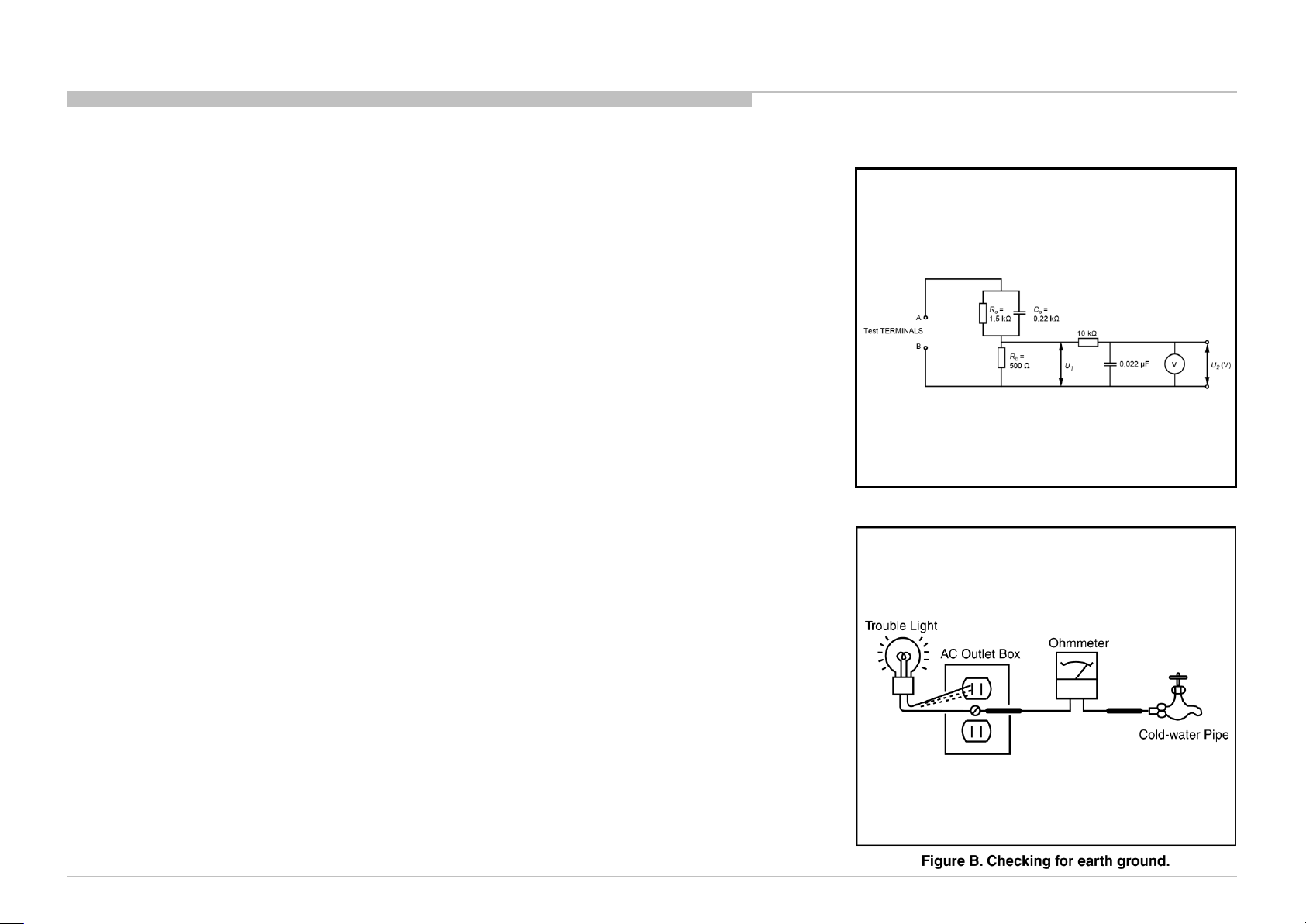
Leakage Test
(To protect electric shock when customer touch the terminal.)
Leakage current can be measured by V: Voltmeter or oscilloscope (r.m.s. or peak reading)
Stabilized power supply instrument and isolated voltage transformer:
Use too much current capacity and isolated voltage transformer does not need to use stabilized power supply
equipment
Specification of RMS volt meter: Input resistance > 1 Mohm, Input capacitance < 200 pF,
Frequency range: 15 Hz – 1MHz (Refer Figure A). Isolated type volt -meter (FLUKE 8921A etc *1)
*1 Not use FLUKE 8920A that connected to protective earth by diode
# Leakage current of measurement instrument is less than 10μArms when under test equipment AC plug is
opened
# Set up the following condition and turn on the set.
Applied voltage: Nominal input voltage (Description on Nameplate)
# Measure the leakage current between one phase conductor and neutral for terminal A and terminal B.
Read rms value, and then calculate to peak value PEAK VALUE =√2 RMS VALUE
Comply with the following requirement
Class II equipment (2-pin plug):
for each terminal, the worst value of measurement must not exceed AC 350uA peak).
Note: including AC adaptor, AC adaptor/DC operated unit combination
How to Find a Good Earth Ground
A cold-water pipe is a guaranteed earth ground; the cover-plate retaining screw on most AC outlet boxes is also
at earth ground.
If the retaining screw is to be used as your earth ground, verify that it is at ground by measuring the resistance
between it and a cold-water pipe with an ohmmeter. The reading should be zero ohms.
If a cold-water pipe is not accessible, connect a 60- to 100-watt trouble- light (not a neon lamp) between the hot
side of the receptacle and the retaining screw. Try both slots, if necessary, to locate the hot side on the line; the
lamp should light at normal brilliance if the screw is at ground potential (see Figure B).
SAFETY CHECK-OUT
Figure A. Measuring network for Leakage Current
KD-55/65/75XE8505,8577,8588,8596,8599,FW-65/75XE8501
7
Page 8

SELF DIAGNOSIS FUNCTION
The units in this manual contain a self-diagnostic function. If an error occurs, the Smart Core Red LED will automatically begin to flash.
The number of times the LED flashes translates to a probable source of the problem.
A definition of the Smart Core Red LED flash indicators is listed in the instruction manual for the user’s knowledge and reference.
If an error symptom cannot be reproduced, the remote commander can be used to review the failure occurrence data stored in memory to reveal past problems and how often these
problems occur.
DIAGNOSTIC TEST INDICATORS
When an error occurs, the Smart Core Red LED will flash a set number of times to indicate the possible cause of the problem.
If there is more than one error, the LED will identify the first of the problem areas.
Result for all of the following diagnostic items are displayed on screen.
If the screen displays a “0”, no error has occurred .
RED LED blinking count Detection Items
2x
3x
4x
5x
6x
7x
8x
<B/G> Main 12V over voltage [MAIN_POWER]
<B/G> Main 5.0V failure [DC_ALERT]
<B/S/G> Audio amp. protection [AUD_ERR]
None
<P/T/G/B> Panel ID EEPROM I2C No ACK (Also panel power failure is a suspect) [P_ID_ERR]
<G/P/B/LD> Backlight failure [BACKLIGHT]
Over temperature protection [TEMP_ERR]
<B/P> Temp. sensor I2C No ACK [TEMP_ERR]
<B> 4KPQ Error (4KPQ WDT)
<G>: Power supply board, <B>: Main board, <T>: T-con board, <LD> LD board,
<P>: Panel module, <S>: Speaker, <Tu>: Tuner board
The following items will be recorded and displayed on screen although they do not carry out the RED LED blinking count.
Record Only Item Detection Items
TU_DEMOD
TCON_ERR <T> T-CON device I2C communication failure
FRCTC_I2C
AUD_ERR_I2C <B> Audio amp I2C communication failure
4KPQ_ERR_I2C
Blue italic: detect at startup sequence only.
KD-55/65/75XE8505,8577,8588,8596,8599,FW-65/75XE8501
<B/Tu> Tuner & Demodulator I2C communication failure
Tuner board set detect signal monitoring
<B> FRC device is not finished Initial sequence
FRC device I2C communication failure
<B> 4KPQ device I2C communication failure
8
Page 9
SI2C013500 - 1/5/2022 12:13 PM
SELF DIAGNOSIS FUNCTION
[SELF DIAGNOSTIC SCREEN DISPLAY]
Format of error timestamps
YYMMDDhh mmss (in UTC)
Example :
120823132523 -> Aug 23 2012 13:25:23 UTC
* On ly whe n time is set, an err or times tam p is s ave d.
Smart Core Red LED blinking count
• Panel Ope rat ion Ti me is recorded ever y 30 min,
but Total Operation Ti me is recorded eve ry 1 h r .
Ther efo re, the panel op. time might bec ome l arg er t han th e total op. tim e.
Total Operation Time [hr] – Boot Count – Panel Operation Time [hr]
For errors with symptoms such as “power sometimes shuts off” or
“screen sometimes goes out” that cannot be confirmed,
it is possible to bring up past occurrences of failure for confirmation on the screen:
In standby mode, press buttons on the remote commander sequentially in rapid
succession as shown below:
Error Item
SELF CHECK
Back
<<
002 MAIN POWER 000000000000 000000000000 000000000000 000
003 DC ALERT 000000000000 000000000000 000000000000 000
003 AUD ERR 150101000018 150101000018 150101000018 003
003 AUD ERR I2C 000000000000 000000000000 000000000000 000
003 TU DEMOD 150101000218 150101000223 150101000105 003
004 LD ERR 000000000000 000000000000 000000000000 000
004 BCM ERR 000000000000 000000000000 000000000000 000
005 TCON ERR 150101000504 000000000000 000000000000 001
005 P ID ERR 000000000000 000000000000 000000000000 000
005 FRCTC I2C 000000000000 000000000000 000000000000 000
006 BACKLIGHT ERR 000000000000 000000000000 000000000000 000
007 TEMP ERR 150101000200 150101000002 000000000000 002
008 4KPQ ERR 000000000000 000000000000 000000000000 000
008 4KPQ ERR I2C 000000000000 000000000000 000000000000 000
00005 00414 00002
[Home]Exit
Error
timestamp
for last
recorded
error
Error
timestamp
for 2nd last
recorded
error
Error count
Error
timestamp
for 3rd last
recorded
error
Since the diagnostic results displayed on the screen are not automatically cleared, always check the self-diagnostic screen.
After you have completed the repairs, clear the result display to “0”.
Panel Operation Time clear : Press the Channel 7 => Channel 0 .
Timestamps and Error Count clear : Press the Channel 8 => Channel 0 .
Total Operation Time and Boot Count clear: Press the Channel 9 => Channel 0 .
To exit the Self Diagnostic screen...
*If you want to finish service mode app, do AC OFF/ON → Service mode app is disabled perfectly
*if you want to move home menu, push <HOME>button → Service mode app do background(not disable perfectly)
KD-55/65/75XE8505,8577,8588,8596,8599,FW-65/75XE8501
9
Page 10
ADJUSTMENT
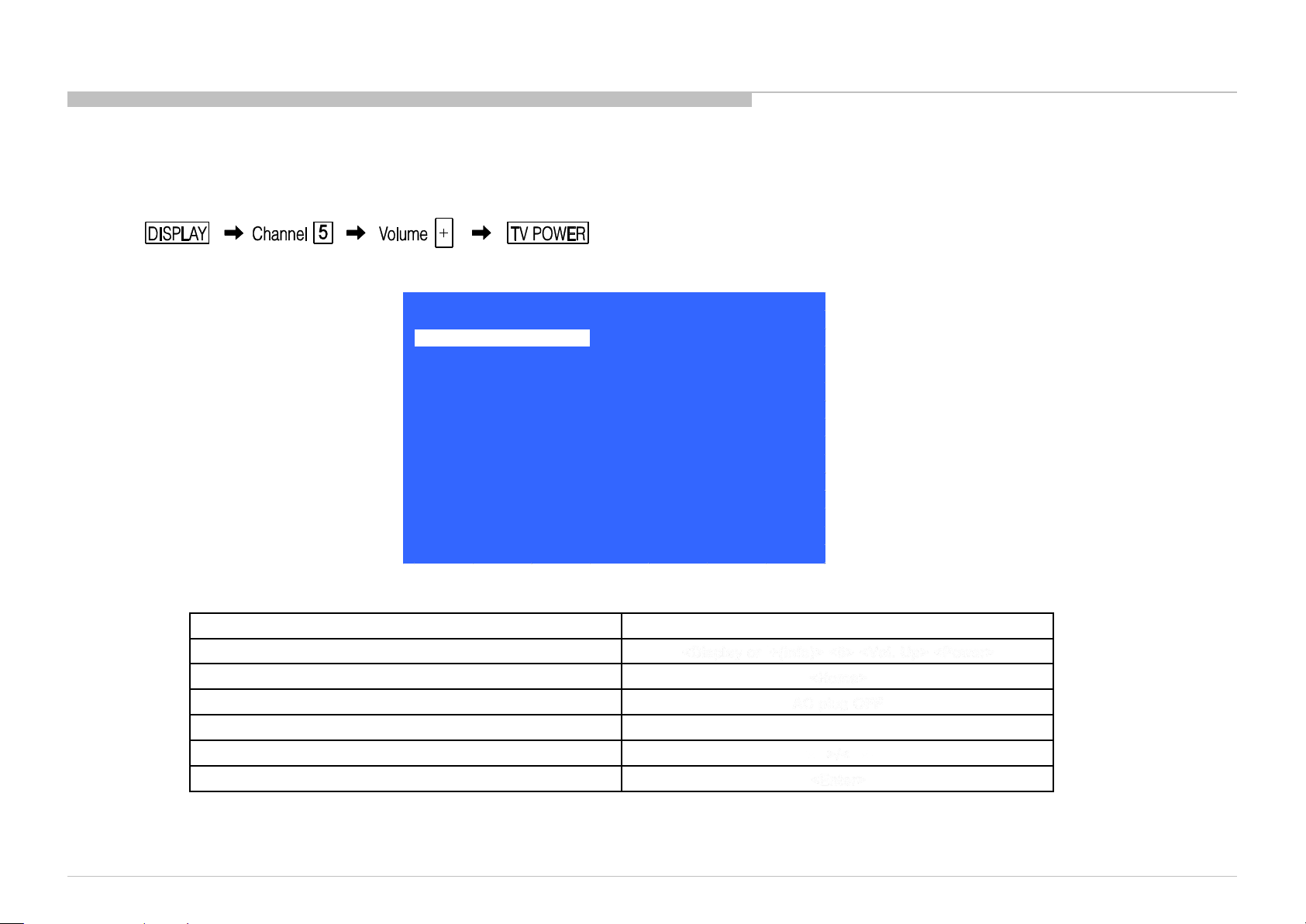
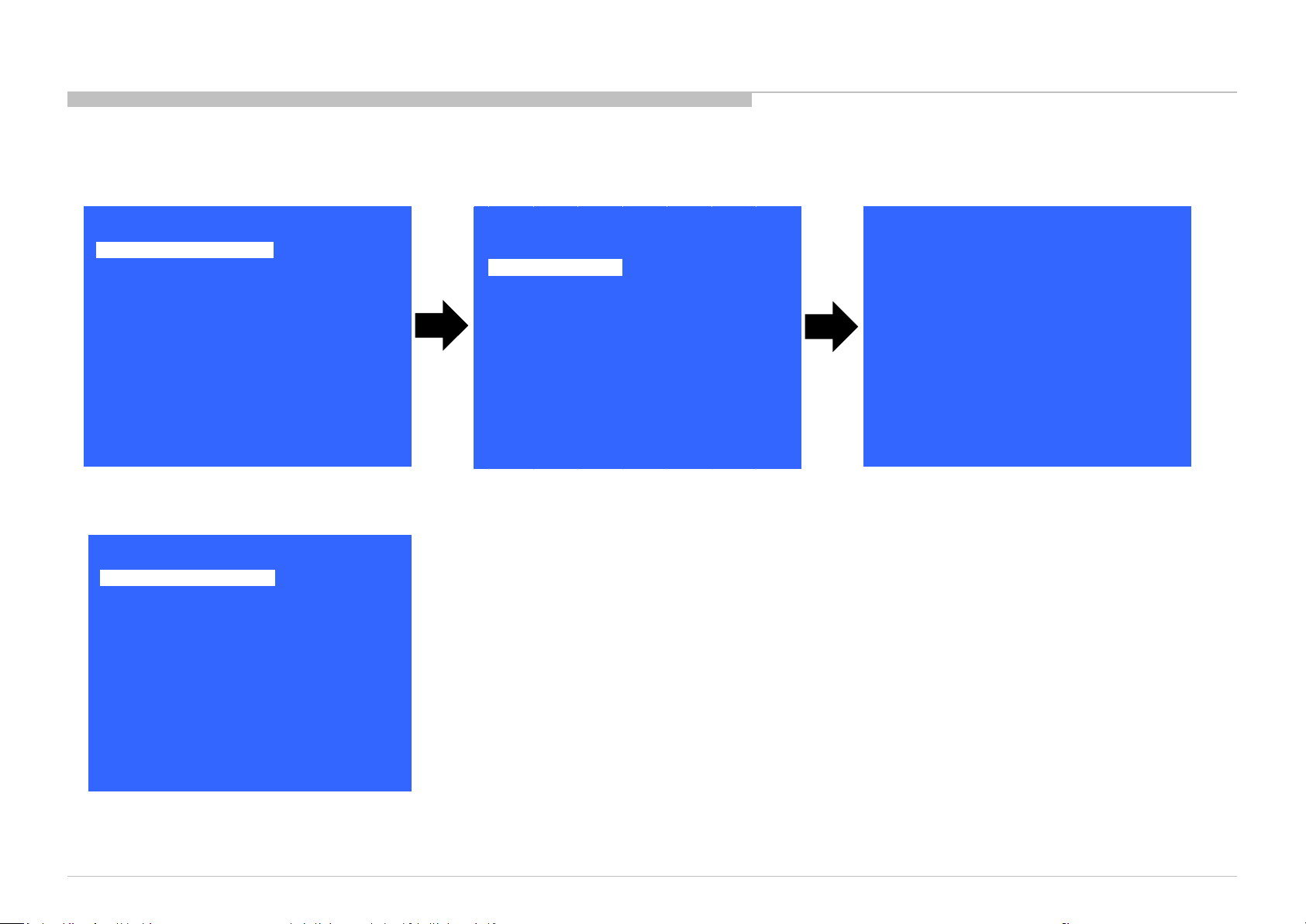
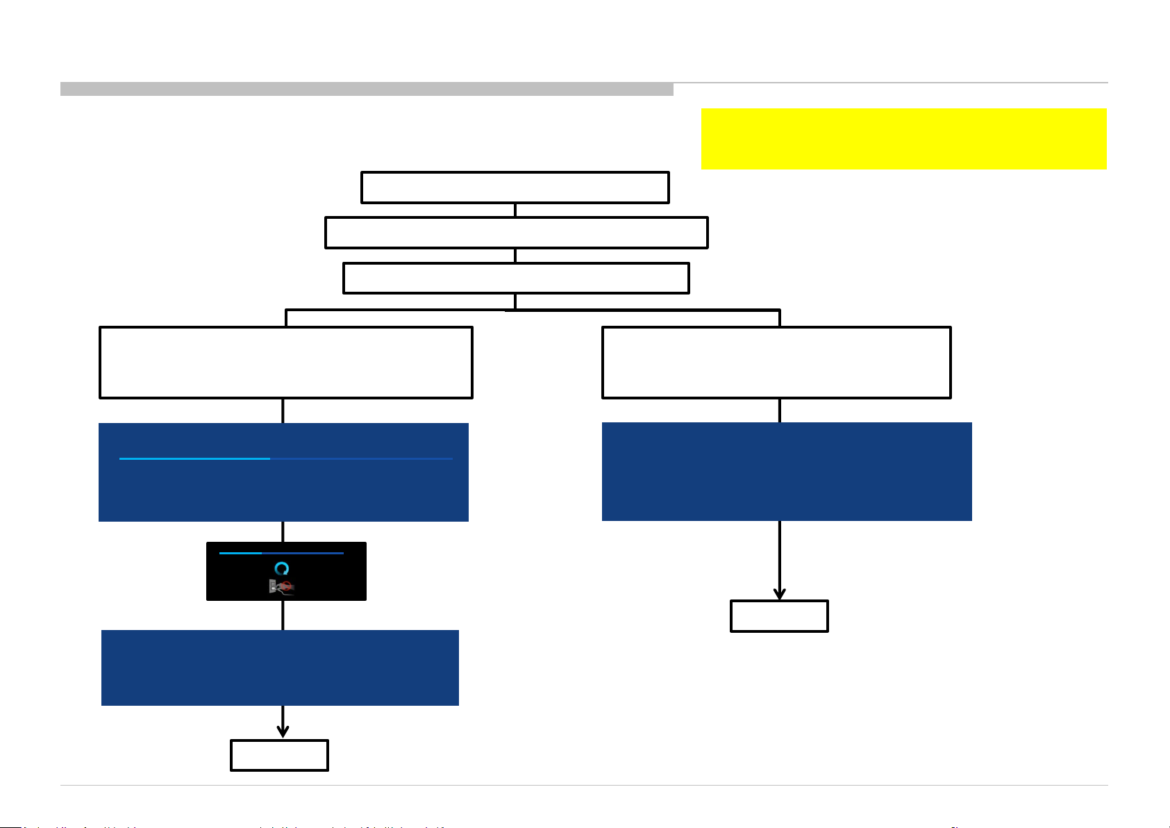
HOW TO ENTERING SERVICE MODE
1) Turn on the main power switch to place the set in standby condition.
2) Press the buttons on the remote commander as follows, and entering service mode.
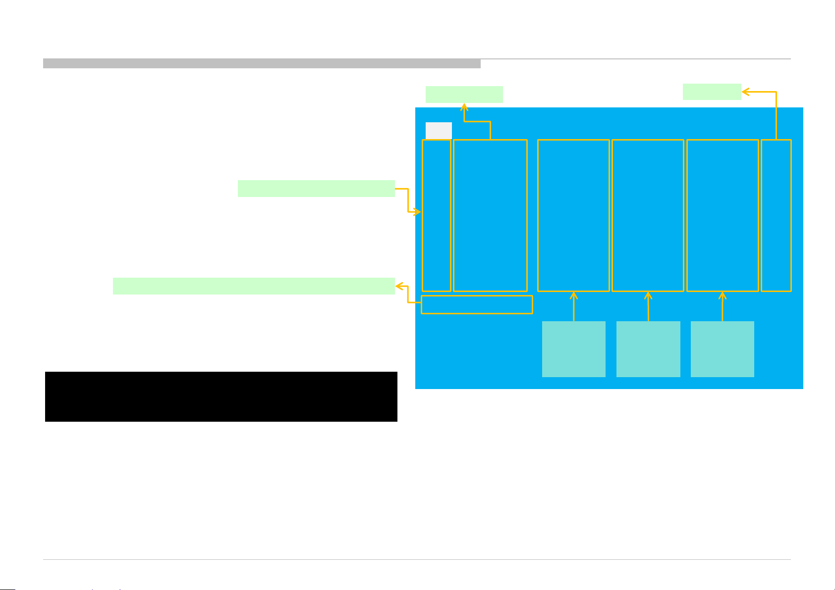
3) Service mode display.
Service Mode
Model Information
Self diagnosis History
Video / Audio
Panel / PQ
General Setting
Tuner
Wi-Fi / BT
>>
>>
>>
>>
>>
>>
>>
>> SDB Service Menu
4) How to use the remote commander.
Function The flow of control
Service mode on <Display or i+ (in fo)> <5> <Vol. Up> <Power>
Close S ervice men u <Home>
Service mode off AC plu g OFF
Item up / down <↑>/ <↓ >
Item select left/right
Execute <Enter>
*When finished the operation of service mode, please AC Plug OFF/ON the TV set.
If you don’t do AC plug OFF/ON, remain the Service Mode App and User can see the Service Mode after RC ON.
(Refer the previous page.)
KD-55/65/75XE8505,8577,8588,8596,8599,FW-65/75XE8501
[Home]Exit
<←>/<→>
10
Page 11
SOFTWARE VERSION
1) In Service Mode, select “Model Information”, press “Enter” or “→” button to enter Status Information.
ADJUSTMENT
Model Information
Self diagnosis History
Video / Audio
Panel / PQ
General Setting
Tuner
Wi-Fi / BT
Service Mode
>>
>>
>>
SI2C013500 - 1/5/2022 12:13 PM
>>
>>
>>
>>
>> SDB Service Menu
[</>] Set [Home]Exit
2) Press “Enter” or “BACK” button to return to Service Mode.
Service Mode
Model Information
Self diagnosis History
Video / Audio
Panel / PQ
General Setting
Tuner
Wi-Fi / BT
>>
>>
>>
>>
>>
>>
>>
>> SDB Service Menu
Model
Status Information
Model Information
Model Number Setting
SERIAL NUMBER EDIT
>>
>>
>>
[</>] Set [Home]Exit
Main Micro
SW Version:
NVM Version:
Boot Version:
PQ Version:
AQ Version:
<ex>
exFRC:
CameraVID:
CameraPIC:
CameraFW:
<4k BE>
MLFW:
MAFW:
ADSP:
NDAT:
PDAT:
BDAT:
BCM:
FDAT:
UDAT:
BDIX:
PKG1.1.0.03.26.1.00.0
0043 CEI
V1.00000000
02000001
AQ2.5030
00.00.00.00
0
0
0
SF0.114
SF2.550
SF0.201
SD2.550
SP2.550
SD2.550
SF------SD0.001
SD0.000
SD2.550
[</>] Set [Home]Exit
KD-55/65/75XE8505,8577,8588,8596,8599,FW-65/75XE8501
11
Page 12
ADJUSTMENT
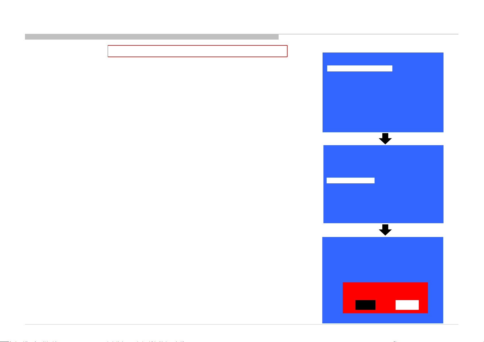
SERIAL NUMBER EDIT (1)
This step is MANDATORY after Main board replacement.
1) In “Service Mode”, select “Model Information” by pressing “↑” or “↓” button then pressing “Enter” or
“→” button to enter inside.
2) Select “Serial Number Edit” by pressing “↑” or “↓” button then pressing “→” button.
3) Press “↑” or “↓” button to input numbers.
4) After user input data, press <Enter> .
• Pop-up dialog appear to confirm input data correct
• Serial Number can be set ONLY ONCE
5) Press “→” or “←” button to select YES or NO.
Select YES if input data is correct.
Select NO if input data is incorrect.
Press <Enter> to save answer.
Model Information
Self diagnosis History
Video / Audio
Panel / PQ
General Setting
Tuner
Wi-Fi / BT
Status Information
Model Information
Model Number Setting
Serial Number Edit
Service Mode
>>
>>
>>
>>
>>
>>
>>
>> SDB Service Menu
[</>] Set [Home]Exit
Model
>>
>>
>>
_ _ _ _ _ _ _
[</>] Set [Home]Exit
* The font color of YES/NO is change to black when it is selected.
KD-55/65/75XE8505,8577,8588,8596,8599,FW-65/75XE8501
Model
Status Information
Model Information
Model Number Setting
Serial Number Edit 9 9 9 9 9 9 9
>>
>>
>>
Input Data correct?
Yes
No
[</>] Set [Home]Exit
12
Page 13

ADJUSTMENT
SERIAL NUMBER EDIT (2)
This step is MANDATORY after Main board replacement.
If YES is selected, the input data is saved into EEPROM.
SERIAL NUMBER EDIT is grayed out and the serial number that has been input is displayed.
Operator will not able to edit anymore.
SI2C013500 - 1/5/2022 12:13 PM
If NO is selected, the input data is not saved into EEPROM.
The serial number that has been input is displayed.
Operator can still edit the Serial Number.
Model
Status Information
Model Information
Model Number Setting
Serial Number Edit 9999999
Model
Status Information
Model Information
Model Number Setting
Serial Number Edit 9 9 9 9 9 9 9
>>
>>
>>
[</>] Set [Home]Exit
>>
>>
>>
Input Data correct?
Yes
No
>>
KD-55/65/75XE8505,8577,8588,8596,8599,FW-65/75XE8501
[</>] Set [Home]Exit
*The font color of YES/NO is change to black when it is selected.
>>
13
Page 14
ADJUSTMENT
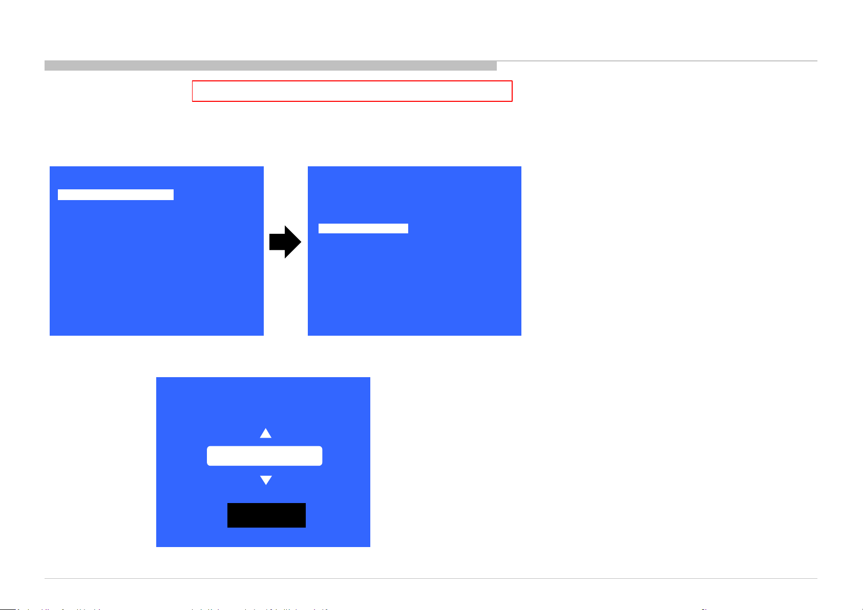
MODEL NUMBER SETTING
This step is MANDATORY after Main board replacement.
1) In “Service Mode”, select “Model Information” by pressing “↑” or “↓” button then pressing “Enter” or “→” button to enter inside.
2) Select “Model Number Setting” by pressing “↑” or “↓” button then pressing “Enter” or “→” button.
3) Press “↑” or “↓” button to scroll Product Name Candidate.
Service Mode
Model Information
Self diagnosis History
Video / Audio
Panel / PQ
General Setting
Tuner
Wi-Fi / BT
>>
>>
>>
>>
>>
>>
>>
>> SDB Service Menu
Status Information
Model Information
Model Number Setting
SERIAL NUMBER EDIT
Model
>>
>>
>>
[</>] Set [Home]Exit
[</>] Set [Home]Exit
4) Select one Product Name from the list. After that select “[OK]” and press “Enter” button.
[MODEL_NUMBER_SETTING]
_ _ _ _ _ _ _ _ _ _ _ _
OK
KD-55/65/75XE8505,8577,8588,8596,8599,FW-65/75XE8501
14
Page 15

SI2C013500 - 1/5/2022 12:13 PM
ADJUSTMENT
WB ADJUSTMENT (If necessary)
In “Panel/PQ” service mode.
a. Go to “WB Adjustment” category by “↑” or “↓”.
Model Information
Self diagnosis History
Video / Audio
Panel / PQ
Tuner
Wi-Fi / BT
SDB Service Menu
Service Mode
>>
>>
>>
>>
>> General Setting
>>
>>
>>
[</>] Set [Home]Exit
b. To select “WB Adjustment”, press “→” button.
Panel / PQ
Back
WB Adjustment
WB/Mura/CUC data transfer
<<
>>
>>
c. To change data, press “←” or “→” button on remote commander.
Back
R WB Gain
<<
<[ 0 ]>
<[ 0 ]> G WB Gain
<[ 0 ]> B WB Gain
<[ 0 ]> R WB Offset
<[ 0 ]> G WB Offset
<[ 0 ]> B WB Offset
[</>] Set [Home]Exit
[</>] Set [Home]Exit
KD-55/65/75XE8505,8577,8588,8596,8599,FW-65/75XE8501
15
Page 16
ADJUSTMENT
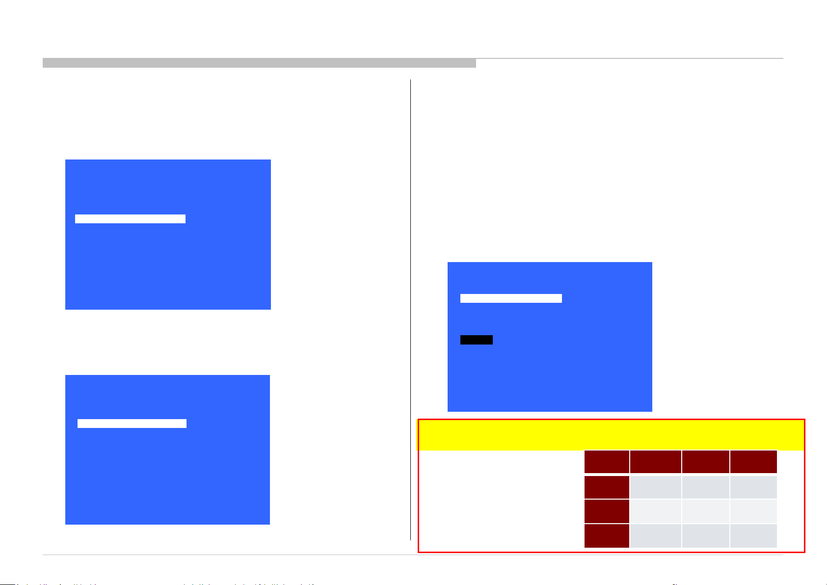
WB/MURA/CUC DATA TRANSFER
(Please apply Main board or panel is replaced.)
1. In “Panel/PQ” service mode.
a. Go to “WB/Mura/CUC data transfer” category by “↑” or “↓”.
Model Information
Self diagnosis History
Video / Audio
Panel / PQ
Tuner
Wi-Fi / BT
SDB Service Menu
Service Mode
>>
>>
>>
>>
>> General Setting
>>
>>
>>
[</>] Set [Home]Exit
b. To select “WB/Mura/CUC data transfer”, press “→” button.
c. To change data, press “←” or “→” button on remote commander.
2. In “WB/Mura/CUC data transfer”.
a. Select “WB/Gamma data transfer” by pressing “↑” or “↓” button on remote commander.
b. To change the items, press “←” or “→” button on remote commander and press “Enter”
button.
Selectable items are:
0. SoC to T-con
1. T-con to SoC
2. No action
c. Similarly, to select the items in Mura and CUC data.
d. Select “[start]” and press “Enter” button to start transfer.
Back
WB / Gamma data transfer
Mura data transfer
Start
<<
<[ 0.Soc to T-con ]>
<[ 0.Soc to T-con ]>
<[ 0.Soc to T-con ]> CUC data transfer
Panel / PQ
Back
WB Adjustment
WB/Mura/CUC data transfer
<<
>>
>>
[</>] Set [Home]Exit
KD-55/65/75XE8505,8577,8588,8596,8599,FW-65/75XE8501
[</>] Set [Home]Exit
*Please refer to another manual “Service Procedure for Panel, Board and Software Change /
Upgrade(P/N:98881800x)” for details. GN3TR chassis is the same as GN1T chassis basically.
WB/
Gamma
Mura
CUC
B-board
replace
1.T-con to
SoC
1.T-con to
SoC
1.T-con to
SoC
T-con
replace
0.SoC to
T-con
0.SoC to
T-con
0.SoC to
T-con
Panel
replace
0.SoC to
T-con
1.T-con
to SoC
1.T-con
to SoC
16
Page 17

HDD PERFORMANCE CHECK
ADJUSTMENT
1. In “Service Mode”, select “General Setting” by pressing “↑” or “↓” button then
pressing “Enter” or “→” button to enter inside.
Model Information
Self diagnosis History
Video / Audio
Panel / PQ
Tuner
Wi-Fi / BT
SDB Service Menu
Service Mode
>>
>>
>>
>>
>> General Setting
>>
>>
>>
[</>] Set [Home]Exit
SI2C013500 - 1/5/2022 12:13 PM
2. Select “HDD Performance check ” by pressing “↑” or “↓” button then pressing
“Enter” or “→” button to enter inside.
General Setting
Back
Aging mode
Ship Confirm
HDD Performance Ch
Update CI+ Credent
ECS_Enable
SCART RGB VREF
<<
<[ Off ]>
>>
>>
>> AAA
>>
<[ Off ]>
<[ Auto ]>
3. A message "Please wait" is displayed during performance check processing.
HDD Performance Check
Please wait…
[</>] Set [Home]Exit
4. Result OK or NG will be displayed after performance of HDD is checked.
HDD Performance Check
<[ ]>
Result
Back
<[ NG ]>
<<
[</>] Set [Home]Exit
[</>] Set [Home]Exit
KD-55/65/75XE8505,8577,8588,8596,8599,FW-65/75XE8501
17
Page 18
HDD RE-REGISTRATION
1. In “Service Mode”, select “General Setting” by pressing “↑” or “↓” button then pressing “Enter” or “→” button to enter inside.
2. Select “AAA” by pressing “↑” or “↓” button then pressing “Enter” or “→” button to enter inside.
ADJUSTMENT
Model Information
Self diagnosis History
Video / Audio
Panel / PQ
Tuner
Wi-Fi / BT
SDB Service Menu
Service Mode
>>
>>
>>
>>
>> General Setting
>>
>>
>>
General Setting
Back
Aging mode
Ship Confirm
HDD Performance Ch
Update CI+ Credent
ECS_Enable
SCART RGB VREF
[</>] Set [Home]Exit
3. Result OK or NG will be displayed after HDD re-registration is succeed/failed.
HDD Re-Register
Result
Back
<[ NG ]>
<<
<<
<[ Off ]>
>>
>>
>> AAA
>>
<[ Off ]>
<[ Auto ]>
[</>] Set [Home]Exit
[</>] Set [Home]Exit
KD-55/65/75XE8505,8577,8588,8596,8599,FW-65/75XE8501
18
Page 19
USB UPDATE
*Please refer to another manual “Service Procedure for Panel, Board
and Software Change / Upgrade(P/N:98881800x)” for details.
GN3TR chassis is the same as GN1T chassis basically.
1:Download USB image and unzip file.
2: copy unzipped file to USB memory root folder.
3: Insert USB memory into USB port on TV.
4-a:USB image is newer soft version.
Automatically show message and start update.
Please follow directions.
System software update
SI2C013500 - 1/5/2022 12:13 PM
Copying USB update file. Please wait…
Preparing for system software update. During the system software update, the TV will
automatically restart. Please do not remove the USB device until an update complete
message is displayed . The update may take up to 15 minutes to complete.
System software update
The system software update is complete .
Some user settings may have changed during the update.
Please remove the USB device and select ”OK” to exit
KD-55/65/75XE8505,8577,8588,8596,8599,FW-65/75XE8501
5: finished
OK
46%
4-b:USB image is not newer soft version.
Automatically show message.
Please follow directions.
System software update
Your software is up to date
Please remove the USB device and select [OK] to exit
OK
5: finished
Caution:
Do not power off while the update is in progress.
19
Page 20
TROUBLE SHOOTING
Remote
Bluetooth (BT)
TU_
DEM
OD
TCON
_ERR
FRCTC
_I2C
AUD_
4KPQ_
No White Power
LED & does not
remote (Dead
Stationary
dots
No video
No video
all Inputs
No Remote
Smart Core no LED
Power
Power
(Backlight)
TEMP
4KPQ
Audio
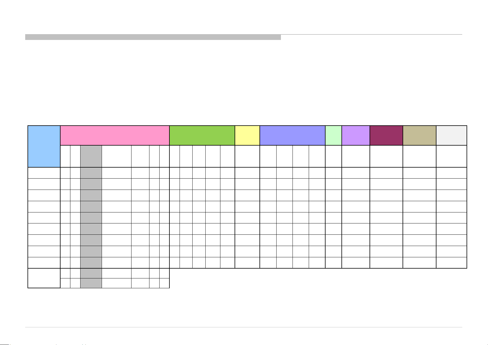
TRIAGE
1. Confirm the symptom from the customer.
2. Select that symptom from the chart.
3. Bring all the boards and cables listed for that symptom.
4. Follow the troubleshooting charts in the technical guides to isolate the board.
5. Chart Color Code.
RED DOT: Most likely defective part
BLUE TRIANGLE: Secondary possible defective part
BLACK TEXT: Board that may correct the symptom
Symptoms - Shutdown. Power LED
blinking red diagnostics sequences
Reference
2 3 4 5 6 7 8
B* Board
G* Board
H* Board
Speaker
Tuner board
Wifi & BT
Module
V By One FFC
Tcon
LCD Panel
Problem
KD-55/65/75XE8505,8577,8588,8596,8599,FW-65/75XE8501
p l
l p
p p l l p p l l l p p l l l p p l p p
p l
p
p
l
p l p
LD
BCM
Panel
(Communication)
Panel
Symptoms - no shutdown
Error log record only
ERR_
l
p
l
I2C
ERR_
I2C
No
Power
respond to
Set)
l
p
Video
- missing or distorted
colored
One of
lines or
Inputs
p l
p
p
l
NO RF
input
Network Audio Smart Core
Wireless
can't connect
p
p
p
l
l
No Audio
p
l
(Set is still alive)
l
Bluetooth /
Voice Remote
can't connect
l
20
Page 21
FLOW
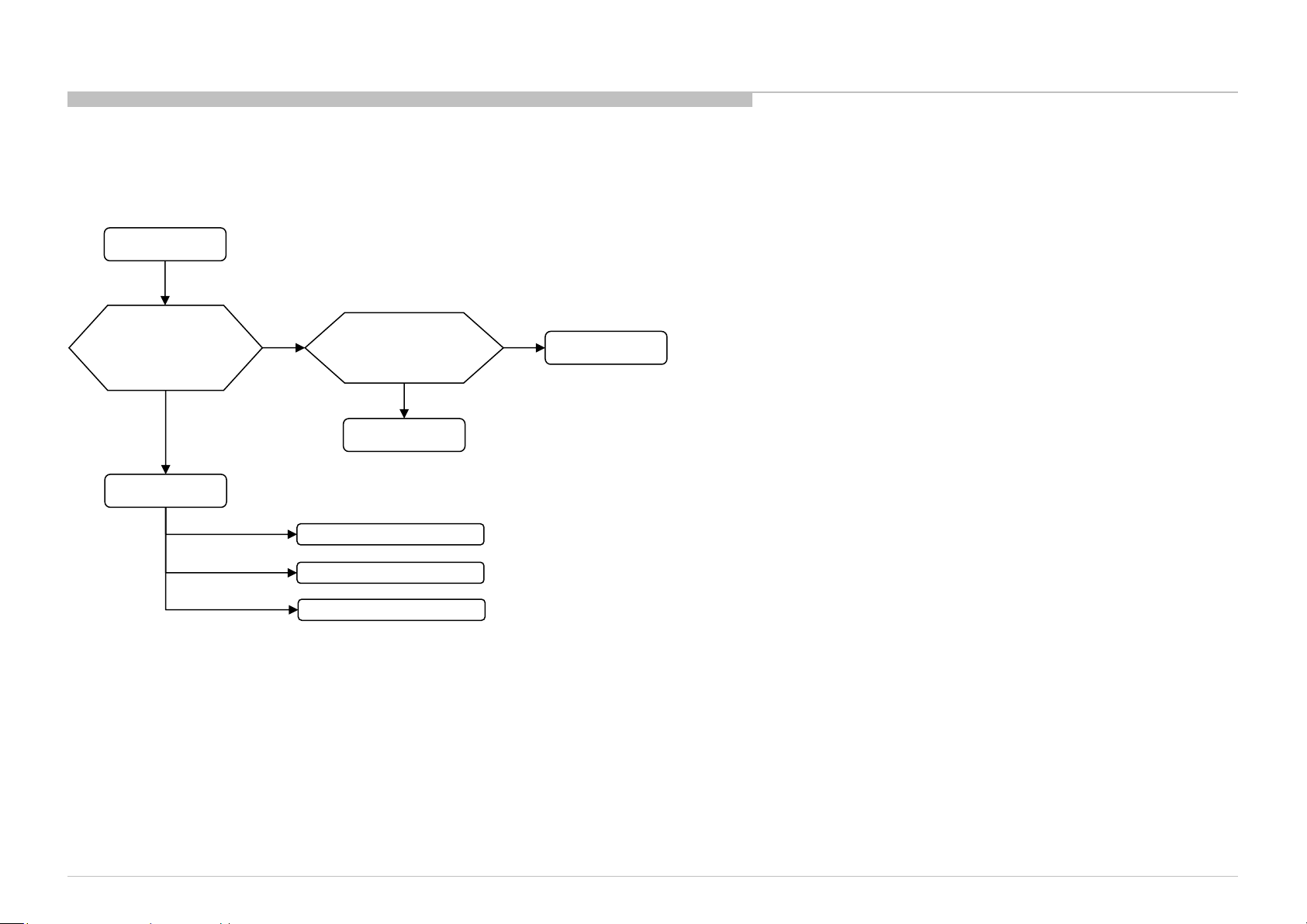
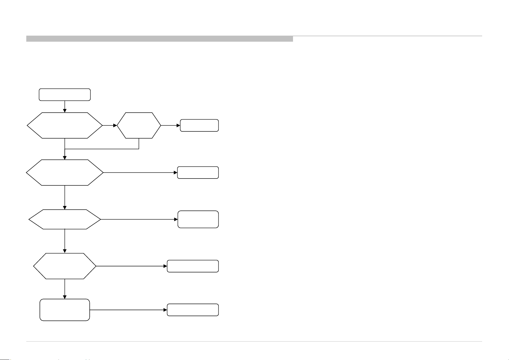
1-1. NO POWER
WITH G* BOARD
No Power
TROUBLE SHOOTING
SI2C013500 - 1/5/2022 12:13 PM
Check STBY 3.3V
C518
near CN400
on B* board
OK
B* board
NG
Replace
Between G* board to
B* board Harness
OK
Harness
u-Com Failure
DDCON/LDO
Main Device Failure
NG
G* board
KD-55/65/75XE8505,8577,8588,8596,8599,FW-65/75XE8501
21
Page 22
FLOW
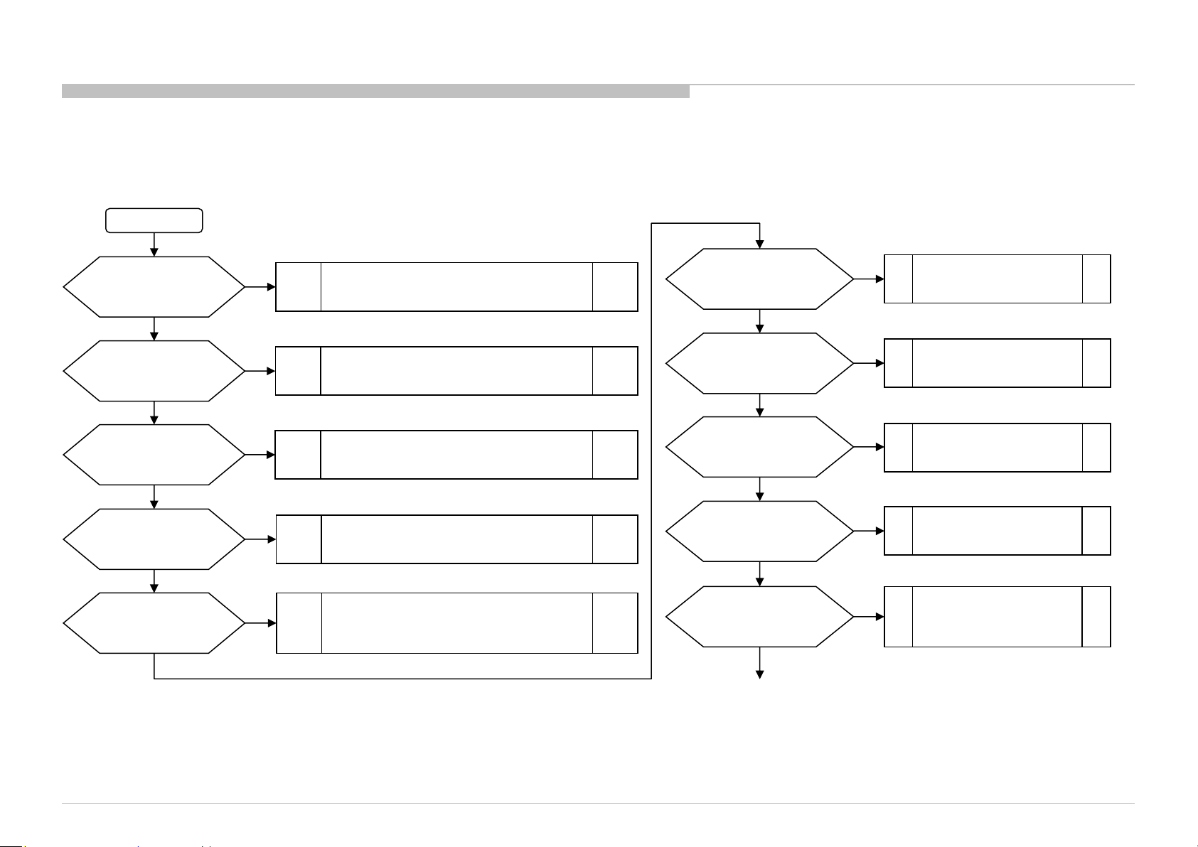
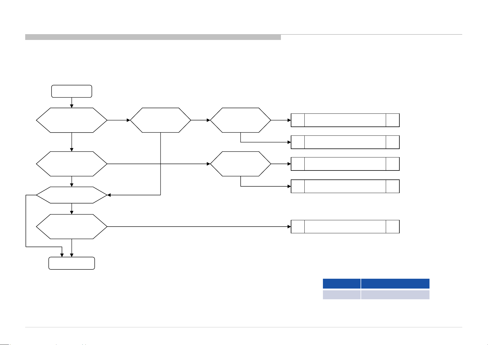
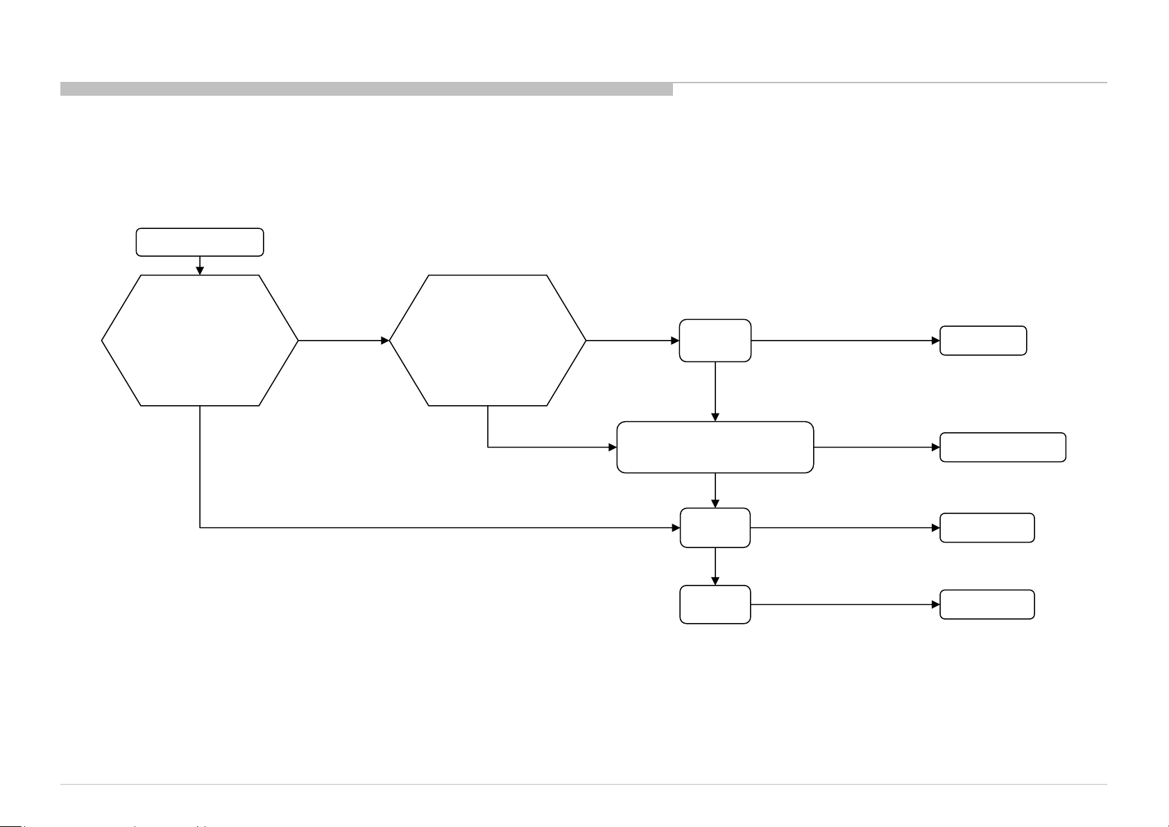
1-2. NO POWER U-COM FAILURE
START
TROUBLE SHOOTING
Check VDD
C506 Voltage.
Is the voltage >3.0V?
yes
(only for AC-ADP model)
Check TYPE_DET
C503 Voltage.
Is the voltage 0V?
yes
(only for G-board model)
Check TYPE_DET
C503 Voltage.
Is the voltage 2.6±0.2V?
yes
Check OPWRSB
R443 Voltage.
Is the voltage 0V?
yes
Check POWER_ON
R526 or P-on ucom #pin10
Is the voltage >3.0V?
yes
no
no
no
no
no
Check +3.3V_STBY LIne (C521, CN400 #14pin)
And (only for AC-ADP model)
3.3V_DDCON (IC403)
Type Detection Circuit problem.
Check TYPE_DET Line (R521, R522, R523).
Check Power supply harness (CN400 #9pin,10pin).
Type Detection Circuit problem.
Check TYPE_DET Line (R521, R522, R523).
Check Power supply harness (CN400 #9pin,10pin).
SOC
Muffin 2
problem
Try AC Off and On after few minutes.
If #pin19 keep Low, change IC401.
If #pin19 goes High few seconds and downs to Low,
Check +12V_MAIN Line (G board or JK board).
Check 12V_MON
R446 Voltage.
Is the voltage >2.6V?
yes
(only for AC-ADP model)
Check DC_MON
R439 Voltage.
Is the voltage >1.8V?
yes
Check DC_OFF_DET
R448 or P-on ucom #pin3
is >3.0V?
yes
Check P_ON_#1
CL418 or P-on ucom #pin12
is >3.0V?
yes
Check PGOOD_1
R440 Voltage.
Is the voltage >3.0V?
yes
no
no
no
no
no
Check +12V_MAIN Line
(G board or JK board).
Check POWER_MAIN Line
(JK board).
Change IC401
Change IC401
No POWER - DDCON/LDO
Check 1.0V DDCON (IC604)
And (only for AC-ADP model)
12V DDCON (IC9000 on JK).
KD-55/65/75XE8505,8577,8588,8596,8599,FW-65/75XE8501
Continue next page
22
Page 23

FLOW
1-2. NO POWER U-COM FAILURE
Previous page
SI2C013500 - 1/5/2022 12:13 PM
Check P_ON_#2
CL417 or P-on ucom #pin13
is >3.0V?
yes
no
Change IC401
TROUBLE SHOOTING
Check P_ON_HL
CL414 or P-on ucom #pin18
is >3.0V?
yes
Check ORESETB
CL416 or P-on ucom #pin14
Is the voltage >3.0V?
yes
Check X_SYSTEM_RST
CL412 or P-on ucom #pin20
Is the voltage >3.0V?
yes
If X_BL_MUTE (R441) is >3.0V
Check BL_ON
R527 or P-on ucom #pin7
Is the voltage >3.0V?
yes
no
Change IC401
no
Change IC401
no
Change IC401
no
Change IC401
END
Ucom IC401 is working OK
KD-55/65/75XE8505,8577,8588,8596,8599,FW-65/75XE8501
23
Page 24
FLOW
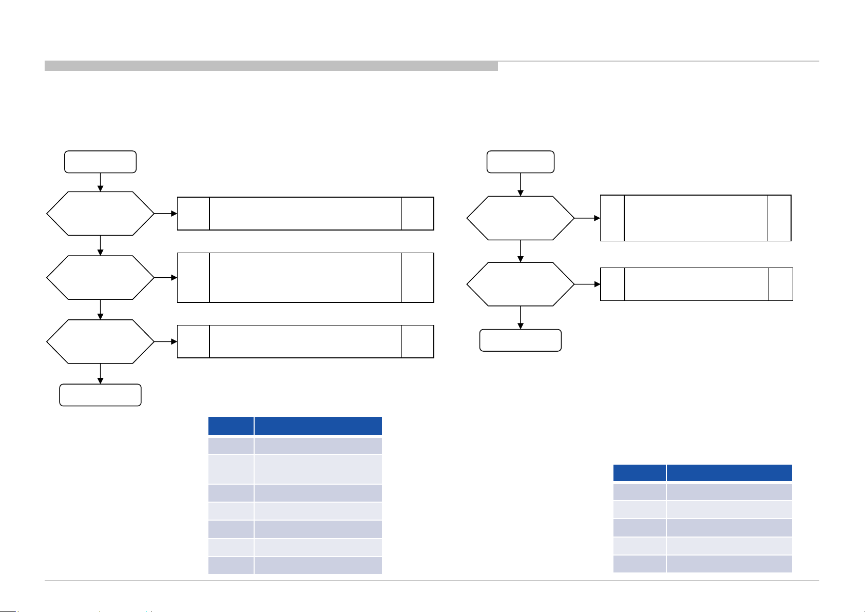
1-3. NO POWER DDCON/LDO
DDCON CHECK
START
TROUBLE SHOOTING
Check IC402 Vcc voltage
Is voltage >12V?
Check Vcc voltage
Is voltage >4V?
Is IC600 mounted?
no
Check Enable
IC600 #pin1
Is voltage >2.5V?
Change DDCON
C423
C602
IC601
yes
yes
yes
yes
no
no
no
Check Vcc voltage
C602
Is voltage >3V?
yes
no
Check
D600
Is diode alive?
yes
Check
D601
Is diode alive?
yes
no
Change D600
Check +3.3V_STBY.
G* board or IC403
no
Change D601
Check +5V_MAIN DDCON (IC402)
Change IC600
KD-55/65/75XE8505,8577,8588,8596,8599,FW-65/75XE8501
IC Ref Voltage supply
IC601 +1.5V_DDR
24
Page 25
FLOW
1-3. NO POWER DDCON/LDO
TROUBLE SHOOTING
DDCONs CHECK
START
Check fuse
F4xx or F6xx
Is fuse OK?
yes
Check Vcc voltage
C4xx or C6xx
Is voltage >12.0V?
yes
Check Enable pin
voltage
Is voltage >2.5V?
SI2C013500 - 1/5/2022 12:13 PM
yes
Change DDCON IC
no
no
no
Change Fuse
1) Check POWER_ON P-on ucom #pin10
(Refer to No Power U-Com Failure)
2) Check G* board
3) Check IC9000 on JK* (only AC-ADP Models)
No Power U-Com Failure
or
Enable source
LDOs CHECK
START
Check Vcc voltage
C6xx
Is voltage >3V?
yes
Check Enable pin
voltage
Is voltage >3V?
yes
Change LDO IC
no
no
Check +3.3V_DDC_OUT
DDCON (IC403)
or
+3.3V_STBY (G* board)
No Power U-Com Failure
or
Enable source
IC Ref Voltage supply
IC402 +5.0V_VBUS/+5V_MAIN
IC403
IC405 +1.8V_TU/+1.8V_BE
IC404 +1.0V_BE
IC409 +1.5V_FRC
IC410 +0.95V_FRC
IC604 +1.0V_M2
KD-55/65/75XE8505,8577,8588,8596,8599,FW-65/75XE8501
+3.3V_STBY (AC-ADP only)
/+3.3V_MAIN
IC Ref Voltage supply
IC602 +1.05V_M2_STBY
IC603 +1.05V_M2_A_1
IC605 +1.05V_M2_ST_ET
IC606 +1.05V_M2_A_2
IC607 VCC3IO_EMMC (1.8V)
25
Page 26
FLOW
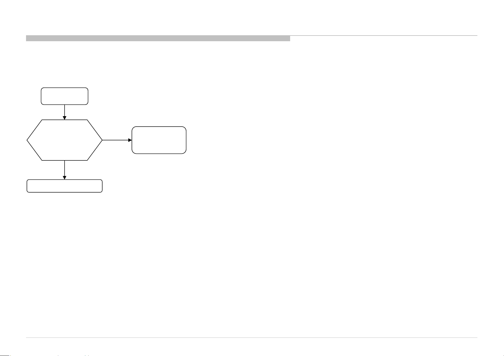
2-1. LED BLINKING 2X (MAIN POWER ERROR)
LED 2x blinking
TROUBLE SHOOTING
Check “+12V_MAIN”
at pin 11/13 of CN400
on B* board,
Voltage > 13.2V ?
No
BMKS / BMKP board
Yes
G board
JK board
AC Adaptor
KD-55/65/75XE8505,8577,8588,8596,8599,FW-65/75XE8501
26
Page 27

FLOW
2-2. LED BLINKING 3X (DC ALERT AND AUDIO ERROR)
TROUBLE SHOOTING
DC_ALERT
3-times blinking
(DC Alert)
Check “POWER_MAIN”
at pin 17/19 of CN400
on B* board,
Voltage = 18.0~20.0V or
22.5~24.5V ?
NG
G board
JK board
AC Adaptor
OK
Check “+5.0V_VBUS”
at C431 on B* board
4.959V<Voltage<5.285V?
NG
BMKS / BMKP board
OK
Other flows
AUDIO ERROR
3-times blinking
(Audio Error)
Go to No Sound (Power Off Check)
Go to No Sound (Power On Check)
Power Off Check
Power On Check
Replace
G board or JK board
or AC Adaptor
NG
Measure the Speaker
impedance by multi-meter
Less than 3Ω ?
No
OK
Yes
G or JK board
or AC Adaptor
Replace
Speaker
KD-55/65/75XE8505,8577,8588,8596,8599,FW-65/75XE8501
Speaker Harness
27
Page 28
FLOW
2-3. LED BLINKING 5X (PANEL ID READ ERROR)
5-times blinking
TROUBLE SHOOTING
Check
“+12.5V_TCON”
at C400 on BMKS
OK
Replace the Harness
Between G/JK board
and BMKS
NG
Replace
the V-By-One FFC
NG
Replace
BMKS board
NG
NG
Symptom improve
Symptom improve
Symptom improve
Replace
G/JK board
NG
OK
G/JK board
Harness
V-By-One FFC
is suspicious
BMKS board
Replace
Panel (T-con)
KD-55/65/75XE8505,8577,8588,8596,8599,FW-65/75XE8501
Symptom improve
G/LD Board: G board or LD board
Panel (T-Con)
28
Page 29
SI2C013500 - 1/5/2022 12:13 PM
FLOW
2-4. LED BLINKING 6X (BACKLIGHT ERROR)
6-times blinking
Check Voltage of
“BL_LD_ERR_DET”
at CL1038 on BMKS
Voltage ≥ 1.9 V
harness/connection
G/LD board to BMKS
Check
Harness /
Connection
broken
Replace
harness
No
improvement
Symptom
Improvement
TROUBLE SHOOTING
Harness
Voltage < 1.9 V
KD-55/65/75XE8505,8577,8588,8596,8599,FW-65/75XE8501
Harness /
Connection OK
LED driver or G board
Replace LD board or G board.
No
improvement
Replace
BMKS
No
Improvement
Replace
Panel
Symptom
Improvement
Symptom
Improvement
Symptom
Improvement
G/LD Board: G board or LD board
LD board/G board
BMKS Board
Panel
29
Page 30

FLOW
2-5. LED BLINKING 7X (TEMPERATURE ERROR)
TROUBLE SHOOTING
2-6. LED BLINKING 8X (4KPQ ERROR)
7-times blinking
Ambient conditions
(temperature , ventilation, etc.)
are OK?
Yes
Replace BMKS/BMKP
board, and Aging a few
hours
Symptom
improvement
BMKS/BMKP board
No
NG
Set to another
location, etc.
Panel
8-times blinking
Replace
BMKS board
Symptom
Improvement
BMKS board
No
improvement
Other flows
KD-55/65/75XE8505,8577,8588,8596,8599,FW-65/75XE8501
30
Page 31

FLOW
3-1. NO SOUND
No Sound
Without LED 3x
TROUBLE SHOOTING
AV receiver is connected
to HDMI in ?
No
[Speakers] setting is
[Audio System] ?
No
Headphone is connected to
HP/Audio Out terminal ?
SI2C013500 - 1/5/2022 12:13 PM
[Headphone Speaker Link]
setting is [On] ?
(POWER OFF CHECK)
No
[Sound]
No
Go to
NO SOUND
Yes
Yes
Yes
Yes
Select [External Inputs]
[BRAVIA Sync Settings]
[BRAVIA Sync Control] [off]
Change the setting to
[TV Speakers]
Disconnect the Headphone
Change [Sound]
[Headphone Speaker Link]
to [Off], OK ?
Yes
HP/Audio out terminal
or Headphone detect
GPIO may be broken
No
Replace B board
No sound only
Analog RF and Digital RF ?
No
No sound only HDMI ?
No
Replace B board
Yes
Yes
NO SOUND ( TUNER)
Go to
Go to
NO SOUND (HDMI)
KD-55/65/75XE8505,8577,8588,8596,8599,FW-65/75XE8501
31
Page 32

FLOW
Speaker Impedance
3-2. NO SOUND (POWER OFF CHECK)
Power Off Check
From LED BLINKING 3X
(AUDIO ERROR)
Power Off Check
From NO SOUND
TROUBLE SHOOTING
3-3. NO SOUND (POWER ON CHECK)
PVDD (POWER_AU) voltage is
Power On Check
From LED BLINKING 3X
(AUDIO ERROR)
240W AC Adaptor model : 24.0V
200W AC Adaptor model : 19.5V
Built-in power supply model : 12.5V
Measurement point is same as (1) PVDD-GND
short check.
PVDD-GND short ?
LDO out short ?
Fuse broken ?
KD-55/65/75XE8505,8577,8588,8596,8599,FW-65/75XE8501
(1) B board
No
(2) B board
No
(3) B board
No
Yes
Yes
Yes
Replace B board
KP woofer 4ohm less than 3.2ohm
KP front 6ohm less than 4.8ohm
KS/KH 8ohm less than 6.4ohm
Rated Impedance NG Value
Measure the Speaker
impedance by multi-meter.
NG value of
right table?
No
Confirm the speaker
harness
Cut or shorted
to the chassis ?
No
Return to
LED BLINKING 3X
(AUDIO ERROR)
or NO SOUND
Yes
Yes
Replace Speaker
Replace Speaker Harness
(4) PVDD check
PVDD is supplied to
B board for a moment
before LED 3x blinking ?
Replace Power-Supply *
Return to LED BLINKING 3X
(AUDIO ERROR)
*Power-Supply is
AC Adaptor model : JK board & AC Adaptor
built-in power supply model : G board
No
No
OK ?
No
Yes
Yes
Finish
32
Page 33

FLOW
3-4. NO SOUND (AUDIO HP/AUDIO OUT)
TROUBLE SHOOTING
3-5. NO SOUND ( TUNER)
No Sound Audio
HP/Audio out
[Sound]
[Headphone/Audio out]
is set to ?
[Audio Out (Fixed)]
[Audio Out (Variable)]
[Subwoofer]
SI2C013500 - 1/5/2022 12:13 PM
[Headphone]
Headphone Volume
is set to MIN?
No
Volume
is set to MIN?
Yes
Increase Headphone Volume
Replace B* board
Replace B* board
Yes
Increase Volume
No
Replace B* board
Set [Headphone/Audio Out]
to [Headphone] or [Audio Out]
No Sound with normal picture
Only RF tuner input?
YES
Check IC1000 (SoC)
NO
Please refer Audio
troubleshooting
KD-55/65/75XE8505,8577,8588,8596,8599,FW-65/75XE8501
33
Page 34

FLOW
3-6. NO SOUND (HDMI)
No Sound
TROUBLE SHOOTING
Check the picture
OK
Check the mode
of Source equipment
HDMI
Does this model have
Analog Audio In
(Stereo minijack)?
NO
Check Sound by other TV set
which is same model
NG
Is Distributor used ?
YES
Connect Source
equipment directly
NG
DVI
YES
NO
Refer to NO PICTURE (HDMI)
Does this model have
Analog Audio In
(Stereo minijack)?
No
“HDMI/DVI Audio Source”
setting is?
Auto or HDMI Audio
OK
Check Source equipment
by Reference TV set
(For example, RB2, RB1)
Check the settings of
Source equipment
YES
Analog Audio In
NG
OK
Connect Stereo minijack cable between Source and the TV,
And Change “HDMI/DVI Audio Source” to Auto or Analog Audio In.
Change the mode of Source equipment to HDMI
Change “HDMI/DVI Audio Source” to Auto or HDMI Audio In
Refer to No Sound
Change B board.
KD-55/65/75XE8505,8577,8588,8596,8599,FW-65/75XE8501
34
Page 35

FLOW
4-1. NO PICTURE
No Picture
TROUBLE SHOOTING
SI2C013500 - 1/5/2022 12:13 PM
BL_ON (L or H): IC401 #7pin (for 4K BMKS/BMKP board)
Got Any Normal
Display?
Yes
Check Other
Portion:
Tuner - No Picture
No
Ext. Video Input -
No Picture
HDMI - No Picture
Check Smart Core
Behavior
(5x Blinking)
Yes
5x Blinking
No
Check
BL_ON
on the B board
BL_ON:L
Backlight
BL_ON:H
Video Analog Signal Path
Video2/Component
(Back/Side)
the V by One FFC
VIDEO_DET
CR_DET
Replace
Harness
Symptom
improvement
V by One FFC
Harness
NG
Replace
The B board
Symptom
improvement
B board NG
SCART_FB/COMP_Y
CVBS2P
SCART_SB/COMP_Y
SCART_SG/COMP_PB
SCART_SR/COMP_PR
NG
LCD Panel
AT35:GPIO56
N35:SOY0
M35:CVBS2P
M38:Y0P
L38:PB0P
L37:PR0P
A16:SD_CLK
(T-CON)
M2
IC1000
KD-55/65/75XE8505,8577,8588,8596,8599,FW-65/75XE8501
Video1
(Side Mini Jack)
CVBS3P
VIDEO2_DET
L36:CVBS3P
G16:GPIO66
35
Page 36

FLOW
4-2. NO PICTURE (VIDEO 1/VIDEO 2/COMPONENT)
VIDEO 1
No Picture
Video 1
No Picture
TROUBLE SHOOTING
Check if input OSD
is GRAY OUT
OK if it is highlighted
Check wave between
C2628 and IC1000
OK
OK (Vpp: 1 V)
Muffin [IC1000]
Problem
NG
NG (Vpp: 0 V)
* Check J2601
Connection,
VIDEO_DET
At R2631
OK (Vpp: 3.3 V)
** Detailed check all
parts at VIDEO2_DET
signal Path [R2630]
OK (Vpp: 3.3V)
J2601
Connector
Problem
NG (Vpp: 0V)
NG (Vpp: 0V)
** Detailed check all parts
at CVBS3P signal path
[D2609/R2629/R2621/C2612
C2628/R2643/VD207]
OK
J2601
Connectivity
Problem
* OK Condition : No solder splash can be seen
NG Condition : Solder splash can be seen
NG
Parts Broken
** OK Condition : No part short-circuited
NG Condition : Part short-circuited
KD-55/65/75XE8505,8577,8588,8596,8599,FW-65/75XE8501
36
Page 37

FLOW
4-2. NO PICTURE (VIDEO 1/VIDEO 2/COMPONENT)
COMPONENT / VIDEO 2
No Picture
TROUBLE SHOOTING
Component
No Picture
SI2C013500 - 1/5/2022 12:13 PM
Check if input OSD
is GRAY OUT
OK if it is highlighted
OK
Check wave
Between
C2602/C2605/C2607
and IC1000
OK (Vpp: 1 V)
Muffin [IC1000]
Problem
NG
* Check J2600 Con
VIDEO_DET at R2626,
CR_DET at R2650
** Detailed check all
parts at VIDEO_DET
signal path [R2627]
signal path [R2637]
NG (Vpp: 0 V)
OK (Vpp: 3.3 V)
and CR_DET
OK (Vpp: 3.3 V)
J2600
Connector
Problem
NG (Vpp: 0 V)
NG (Vpp: 0 V)
R2639/R2604/VD2602/C2602]
PB0P : [VD2603/R2603/C2601/
PR0P : [VD2601/R2610/C2606/
J2600
Connectivity
Problem
** Detailed check all parts
at signal path of:
Y0P : [D2601/R2606/C2603/
R2638/R2607/C2605]
R2611/C2607]
OK
NG
Parts Broken
Video 2
No Picture
Check if input OSD
is GRAY OUT
OK if it is highlighted
OK
Check wave between
C2611 and IC1000
OK (Vpp: 1 V)
Muffin [IC1000]
Problem
NG
** Detailed check all
parts at VIDEO_DET
signal Path [R2627]
NG (Vpp: 0 V)
* Check J2600
Connection,
VIDEO_DET
At R2626
OK (Vpp: 3.3 V)
OK (Vpp: 3.3 V)
J2600
Connector
Problem
NG (Vpp: 0 V)
NG (Vpp: 0 V)
Connectivity
J2600
Problem
** Detailed check all parts
at CVBS2P signal path
[D2601/R2606/C2603/
R2640/R2619/
C2611/VD2602]
OK
NG
Parts Broken
KD-55/65/75XE8505,8577,8588,8596,8599,FW-65/75XE8501
* OK Condition : No solder splash can be seen
NG Condition : Solder splash can be seen
** OK Condition : No part short-circuited
NG Condition : Part short-circuited
37
Page 38

FLOW
4-3. NO PICTURE (TUNER)
RF input no picture / noisy picture
Check RF source cable
and antenna, OK?
OK
Check Tuner power line:
3.3V at JL2800 = 3.3V?
1.8V at JL2801 = 1.8V?
A_RESET value at JL2807 = 3.3V?
OK
All broadcasting channel
cannot be received?
NO
NG
YES
NG
Change RF cable and antenna
Please refer DDCON
troubleshooting
Check part mounting condition
for I2C SDA & SCL line. (Refer Note I2C)
And
Check Tuner module connection.(CN2800)
OK
Notes: I2C
I2C line for all tuners except Japan_SKP
- Parts for I2C SDA line: R2800, C2803.
- Parts for I2C SCL line : R2801, C2804.
I2C line for Japan_SKP
- Parts for I2C SDA line: R2804
- Parts for I2C SCL line : R2805
NG
Change NG parts
connected to I2C bus
TROUBLE SHOOTING
Digital
Analog
Refer Analog Tuning
KD-55/65/75XE8505,8577,8588,8596,8599,FW-65/75XE8501
Refer Digital Tuning 1
Terrestrial/Cable
For TW, NA-ATSC(MX/UC),
JP_SKP(Opticast) and LA-ISDB-T
Refer Digital Tuning 2
OK
For AEP_W, JP_SKP, PA_T2,
CH/HK, and LA-T2(COL)
Check Tuner power line
12V at JL2822 = 12V?
Satellite
NG
12V LNB Voltage Checking
38
Page 39

FLOW
4-4. NO PICTURE (TUNER)
FOR 12V LNB VOLTAGE CHECKING
+12V_LNB Voltage Checking
TROUBLE SHOOTING
Check fuse F2800
NG
Change the fuse
OK
Check LNB power line
+12V_MAIN at R495 = 12V?
NG
AC adaptor or G-board
G-board
SI2C013500 - 1/5/2022 12:13 PM
Check harness between
B-Board and G-board
OK
Please refer G-board
troubleshooting
OK
AC adaptor
NG
Check P_ON_HL signal line
at R451 (CL414) = 3.3V?
NG
Please refer DDCON
troubleshooting
Harness broken
OK
MOSFET Q408/Q409
broken
KD-55/65/75XE8505,8577,8588,8596,8599,FW-65/75XE8501
39
Page 40

FLOW
4-4. NO PICTURE (TUNER)
FOR ANALOG TUNING
Analog Tuning
For LA-ISDB(BR/AR), LA-T2(COL) and TW only
TROUBLE SHOOTING
For Other destination
Can it preset broadcast?
Check part mounting condition
for analog control line
“IFOUT_N, IFOUT_P, IFAGC”
Change NG parts
Confirm ANT or Cable connection
NG
NG
OK
OK
OK
NG
A
Tuner module connection (CN2800)
Notes:
- Parts for IFOUT_N line : FB2801, C2807, C2826
- Parts for IFOUT_P line : FB2802, C2808, C2825
- Parts for IFAGC line : R2838, C2827
: Insert correct signal in correct terminal. A
Check IC1000 (SoC)
Check IC1000 (SoC) &
KD-55/65/75XE8505,8577,8588,8596,8599,FW-65/75XE8501
40
Page 41

FLOW
4-4. NO PICTURE (TUNER)
FOR DIGITAL TUNING 2
TROUBLE SHOOTING
Digital Tuning 2
LA-T2(COL)
Confirm ANT or Cable connection Confirm ANT or Satellite connection
OK
Digital cable/ Terrestrial
Cable
Refer to Digital Tuning 1
SI2C013500 - 1/5/2022 12:13 PM
NG
A A A
Terrestrial
Sound is normal?
Display the service mode screen
Check part mounting condition for digital data line
“TU1_TS_DATA0, TU1_TS_CLK,
TU1_TS_VALID, TU1_TS_SYNC”
(Refer Notes)
Change NG parts
For PA_T2 and
CH/HK
OK
No sound
CASE B
TS_LOCK ?
UEC ?
CASE A
NG
For AEP-W
OK
Check IC1000 (SoC)
Change Tuner module
OK
Check IC1000 (SoC) &
Confirm an insertion state of the
connector
For JP_SKP
NG NG
All except SKP_Opticast
Confirm ANT or Satellite connection
OK
BS/CS or SKP_Opticast/
SKP_Premium or terrestrial
SKP_Opticast
Refer to Digital Tuning 1
Notes:
- Parts for TU1_TS_DATA0 line : R2847
- Parts for TU1_TS_CLK line : R2844
- Parts for TU1_TS_VALID line : R2845
- Parts for TU1_TS_SYNC line : R2846
- CASE A : TS _LOCK = LOCK and UEC constant
- CASE B : TS _LOCK = UNLOCK or UEC is increasing
A
: Insert correct signal in correct terminal.
KD-55/65/75XE8505,8577,8588,8596,8599,FW-65/75XE8501
41
Page 42

FLOW
4-5. NO PICTURE (HDMI)
HDMI1
No Picture
TROUBLE SHOOTING
Check other
HDMI input
All Inputs are NG
Check Picture by other TV set
which is same model
Target board & other TV set
both NG
Is Distributor used ?
NO
Check Source equipment
by Reference TV set
(For example, RB1)
Reference TV set
NG
Check the settings of
Source equipment
Other Input is OK
Other TV set
OK
YES
Reference TV Set
OK
Replace
IC1000
Connect Source
equipment directly
Change B* board.
And inform the designer of it
+5V line only NG
Spec:4.7~5.3V
Replace
R3646
Check the below point at
Connector side
- Check +5V line
- Check HPD line
- Check DDC lines
- Check TMDS lines
+5V line is OK
and HPD line is NG
Spec:2.4~5.3V
Replace
R3627,R3634,R3639,
R3643,Q3602
NG
Replace IC1000.
And inform the designer of it
All lines
are NG
DDC lines
only NG
Replace
RB3603,R3664,R3665
NG
Replace
CN3603
TMDS lines
only NG
Replace
RB3619,RB3620,
RB3611,RB3612
NG
NG
KD-55/65/75XE8505,8577,8588,8596,8599,FW-65/75XE8501
42
Page 43

TROUBLE SHOOTING
FLOW
4-5. NO PICTURE (HDMI)
HDMI2
No Picture
Check other
HDMI input
Check Picture by other TV set
which is same model
Is Distributor used ?
Check Source equipment
by Reference TV set
(For example, RB1)
SI2C013500 - 1/5/2022 12:13 PM
All Inputs are
NG
Target board & other TV
set both NG
NO
Reference TV set
NG
Other Input is OK
Other TV set
OK
YES
Reference TV Set
OK
Replace
IC1000
Connect Source
equipment directly
Change B* board.
And inform the designer of it
+5V line only NG
Spec:4.7~5.3V
Replace
R3647
Check the below point at
Connector side
- Check +5V line
- Check HPD line
- Check DDC lines
- Check TMDS lines
+5V line is OK
and HPD line is NG
Spec:2.4~5.3V
Replace
R3619
NG
Replace IC1000.
And inform the designer of it
All lines
are NG
DDC lines
only NG
Replace
RB3604,R3658,R3659
NG
Replace
CN3600
TMDS lines
only NG
Replace
RB3613,RB3614,
RB3605,RB3606
NG
NG
Check the settings of
Source equipment
KD-55/65/75XE8505,8577,8588,8596,8599,FW-65/75XE8501
43
Page 44

FLOW
4-5. NO PICTURE (HDMI)
HDMI3
No Picture
TROUBLE SHOOTING
Check other
HDMI input
All Inputs
are NG
Check Picture by other TV set
which is same model
Target board & other TV
set both NG
Is Distributor used ?
NO
Check Source equipment
by Reference TV set
(For example, RB1)
Reference TV set
NG
Check the settings of
Source equipment
Other Input is OK
Other TV set
OK
YES
Reference TV Set
OK
Replace
IC1000
Connect Source
equipment directly
Change B* board.
And inform the designer of it
+5V line only NG
Spec:4.7~5.3V
Replace
R3644
Check the below point at
Connector side
- Check +5V line
- Check HPD line
- Check DDC lines
- Check TMDS lines
+5V line is OK
and HPD line is NG
Spec:2.4~5.3V
Replace
R3625,R3632,R3637,
R3641,Q3600
NG
Replace IC1000.
And inform the designer of it
All lines
are NG
DDC lines
only NG
Replace
RB3601,R3660,R3661
NG
Replace
CN3601
TMDS lines
only NG
Replace
RB3615,RB3616,
RB3607,RB3608
NG
NG
KD-55/65/75XE8505,8577,8588,8596,8599,FW-65/75XE8501
44
Page 45

FLOW
4-5. NO PICTURE (HDMI)
HDMI4
No Picture
TROUBLE SHOOTING
Check other
HDMI input
All Inputs
are NG
Check Picture by other TV set
which is same model
Target board & other TV
set both NG
Is Distributor used ?
NO
Check Source equipment
by Reference TV set
(For example, RB1)
Reference TV set
NG
Check the settings of
Source equipment
Other Input is OK
Other TV set
OK
YES
Reference TV Set
OK
Check the below point at
Connector side
- Check +5V line
- Check HPD line
- Check DDC lines
- Check TMDS lines
Replace
IC1000
SI2C013500 - 1/5/2022 12:13 PM
Connect Source
equipment directly
Change B* board.
And inform the designer of it
+5V line only NG
Spec:4.7~5.3V
Replace
R3645
R3626,R3633,R3638,
Replace IC1000.
And inform the designer of it
+5V line is OK
and HPD line is NG
Spec:2.4~5.3V
Replace
R3642,Q3601
NG
All lines are
NG
DDC lines
only NG
Replace
RB3602,R3662,R3663
NG
Replace
CN3602
TMDS lines
only NG
Replace
RB3617,RB3618,
RB3609,RB3610
NG
NG
KD-55/65/75XE8505,8577,8588,8596,8599,FW-65/75XE8501
45
Page 46

FLOW
5. KEY SWITCH BUTTONS ERROR
TROUBLE SHOOTING
Side key buttons error
Resistor value
[BMKS]
R1108 : 0 [ohm]
R1049 : 47k [ohm]
R1222 : 4.7k [ohm]
[BMKP]
R250 : 0 [ohm]
R232 : 47k [ohm]
R1222 : 4.7k [ohm]
Resistor value
[BMKS]
R1028 : 4.7k [ohm]
R1107 : 0 [ohm]
R1050 : 20k [ohm]
R1051: 22k [ohm]
[BMKP]
R1028 : 4.7k [ohm]
R249 : 0 [ohm]
R230 : 20k [ohm]
R231: 22k [ohm]
Check harness connection
between B*board and switch
Change harness between B*
Check resistor value on B*
Check resistor value on B*
module
NG
board to switch module
harness
NG
Change switch module Switch module issue
NG
board
OK
In case that power key error
board
In case that buttons error except power key
OK
OK
OK
OK
NG
NG
Harness connection issue
B* board to switch module harness
issue
Parts issue
Main device issue
Change B* board
KD-55/65/75XE8505,8577,8588,8596,8599,FW-65/75XE8501
46
Page 47

FLOW
6. IR REMOTE COMMANDER ERROR
TROUBLE SHOOTING
SI2C013500 - 1/5/2022 12:13 PM
Resistor value
[BMKS]
R1110 : 0 [ohm]
R1259 : 47k [ohm]
[BMKP]
R252 : 0 [ohm]
R1259 : 47k [ohm]
IR remote commander does not
respond
Center white LED blinks when
pushing buttons of remote
commander at close to IR
sensor.
NG
Check harness connection
between B*board and Smart
Core
NG
Change harness between B*
board to Smart Core harness
NG
Change Smart Core Smart Core issue
NG
Check resistor value on B*
board
OK
OK
OK
OK
OK
NG
Battery of remote commander
Harness connection
B* board to Smart Core harness
Change B* board
Main device issue
could be weak.
Change battery.
issue
issue
Parts issue
KD-55/65/75XE8505,8577,8588,8596,8599,FW-65/75XE8501
47
Page 48

FLOW
7. LIGHT SENSOR ERROR
Backlight level does not change
when ambient light changed
TROUBLE SHOOTING
Check UI setting and make
sure light sensor setting is
“ON”
Setting is “OFF”
Setting issue
Change setting to “ON”
Resistor value
[BMKS]
R1109 : 0 [ohm]
R1052 : 150k [ohm]
[BMKP]
R251 : 0 [ohm]
R233 : 150k [ohm]
Setting is “ON”
Check harness connection
between B*board and Smart
Core
NG
Check harness connection
between B*board and H-
board
NG
Change harness between B*
board to Smart Core harness
NG
Change Smart Core Smart Core issue
NG
Check resistor value on B*
board
OK
OK
OK
OK
OK
NG
Battery of remote commander
could be weak.
Change battery.
Harness connection
issue
B* board to Smart Core harness
issue
Parts issue
Change B* board
Main device issue
KD-55/65/75XE8505,8577,8588,8596,8599,FW-65/75XE8501
48
Page 49

FLOW
8. NETWORK MALFUNCTION
ETHERNET (WIRED)
[Network Set-up]
>[Wired Set-up]
on the TV
TROUBLE SHOOTING
Connection Results
Cable Connection
Check cable
Ethernet Cable
B Board
CHK1
Any scratches
along
TX+/-, RX+/-
lines?
Failed
NG
YES
OK
OK
NO
B* board
CHK2
Check Ethernet
Connector pins
Soldering
Check
OK
Auto
NG
Check
Local router
DHCP server
OK
Connection Results
Local Access
Failed
Wired Set-up
IP address setting
SI2C013500 - 1/5/2022 12:13 PM
Check IP address
Local router setting
OK
J3400
NG NG
Manual
&
CHK3
Pulse Transformer
soldering
T3400,T3401
Connection Results
Internet Access
CHK4
Check CMF
Soldering
L3400
Failed
Proxy setting
OK
OK
B* board
IC1000 problem.
Change B* board
Change B* board
KD-55/65/75XE8505,8577,8588,8596,8599,FW-65/75XE8501
Change
Ethernet Connector
Change Pulse Trans
Change CMF
49
Page 50

FLOW
9. NETWORK MALFUNCTION
INTERNAL WIRELESS NETWORK MALFUNCTION
Wireless Network
on the TV
TROUBLE SHOOTING
Error message or no scan result appear in
the network setting?
Yes
Hardware defect suspected
Check harness
connection is OK
between Wi-Fi and B*
OK
Check with another Wi-Fi module
OK
Wi-Fi module
NG
NG
No
Is the Wi-Fi radio
strength too weak
or even No signal?
Yes
Check with another Wi-Fi
module
OK
Connect properly
NG
Change harness
between B* board and Wi-Fi
OK
Main Harness
OK
NG
No
NG
B* board
Access Point
WiFi module
Loose harness
B* board
If Wi-Fi malfunction happens,
・Wi-Fi module
・Harness between WiFi and B*
・B* board
are suspected.
KD-55/65/75XE8505,8577,8588,8596,8599,FW-65/75XE8501
50
Page 51

FLOW
10. BLUETOOTH MALFUNCTION
TROUBLE SHOOTING
Voice Remote doesn’t work
Bluetooth Keyboard/Mouse doesn’t work
Home > Settings >
Bluetooth Settings
NG
else
Check harness
connection is OK
between BT and B*
OK
Change BT module
or
OK
Can read
Near discoverable
Bluetooth Device
NG
NG
Check BT antenna
Connection is OK
Connect properly
NG
Between B* board and BT
NG
Change harness
OK
NG
Connect properly
OK
NG
OK
Loose harness
Change B* board
Please refer
Voice Remote manual
or
Bluetooth Keyboard/Mouse operation manual
Loose BT antenna
connection
OK
BT module
KD-55/65/75XE8505,8577,8588,8596,8599,FW-65/75XE8501
OK
Main Harness
51
Page 52

PCB PARTS MAP
BMKS (A side view)
cam013
cam001
cam033
1
cam027
2
2
R4083
4
cam003
KA002
43
42
44 4
5 4
6
400
CN4
4
7 4
8
49
141
51
50
53
52 61
5
1
4
CN4401
5
95
1
60
1
CN4000
2313
03
R11
R1101
R1100
S1000
ON
30
CN400
2
F3200
C414
cam004
KJ001 KJ002
R4071
R4081
R4077
R4072
R4066
IC4002
CN4001
CN4003
1
5 6
cam026
IRM002
D4400
R4408
Q4400
R4414
D4401
R4416
Q4401
R4412
cam021
CL4417
R4439
CL4418
R4440
CL4419
CL4436
C4411
CL4420
R4441
CL4421
C4412
R4241
CL4422
R4442
CL4
C4413
423
CL4424
R4443
C4414
CL4425
R4239
CL4426
R4444
C4415
CL4427
R4445
CL4428
C4416
R4452
CL4429
R4446
CL4430
C4417
CL4431
CL4437
R4451
C4418
CL4432
RB4400
RB4402
RB4401
RB4403
R1079
R1080
R1081
R1082
TP209
R1083
84
R10
cam022
RB4404
RB4405
RB4406
RB4407
C4402
R4425
CL4402
R4426
CL4403
C4403
R4427
CL4404
CL4406
R4429
R4428
CL4405
CL1214
R4430
C4408
CL4407
R4405
R4431
C4404
C4405
CL4408
R4432
R4406
CL1213
RB4408
C4409
R4418
R4062
R4433
R4058
C4410
R4434
CL4434
CL4433
CL4412
CL4413
CL4414
CL4415
C4406
R4436
R4435
R4437
R4438
C4407
R4449
C40
R4057
C4420
C4419
C4085
R4447
C4071
C4068
C3816
C3812
C3806
C3804
R4424
C4069
C3818
C3802
C3800
C3810
C3814
CL4416
C3808
R3803
R3804
R4422
R4423
R4421
R4059
C4094
R4041
C4065
CL4045
R4036
R4052
RB4000
C4063
R546
CM406
cam44
C4088
C4084
C4080
C4070
66
C40
C4075
C4091
C4082
C4067
C4077
C4073
C4086
R4045
C4025
C4026
R4012
C4027
CL4053
C4059
C4061
C4064
R4013
C4028
R4014
CL4043
CL4042
C4029
R4015
R4037
R4043
R4042
R4016
C4030
R4022
R4018
C4031
R4029
C4019
C4032
C4033
R4098
C4034
R482
C450
R480
R483
02
C449
8 5
C451
R481
9
IC404
C453
41
C454
C452
F402
cam50
L403
cam002
cam100007
C400
29
C401
C405
R403
C402
R400
C407
R405
C403
R401
C408
R406
C404
R402
C411
R407
C406
R404
C412
R408
C409
C410
D402
C517
C516
TP204
C518
C515
R409
C417
R411
R522
C492
R410
C416
R412
R523
C415
56
14
1
R413
cam043
C433
cam45
C413
C3243
R3239
R3242
611
C3244
1732
C3252
C3254
C3274
C3249
L3203
C3275
L3201
C3276
C3265
cam012
cam32
1 4
cam005
5 6
cam901
cam006
CN4200
R4079
54815
R4065
R4064
13
R4082
14
14
R4086
R4063
R4090
CL4051
C4104
1
ET212
C4235
C4234
R4240
C4237
C4232
C4233
R4213
R4211
CL4210
CL4208
cam039
C4230
R4212
CL4209
CL4211
C4231
R4214
C4228
C4229
C4226
C4227
C4224
C4225
C4222
C4223
C4220
C4221
C4218
C4219
C4216
C4217
C3851
C3857
C3893
C3885
C3891
C3888
C3892
C3852
C3856
R4225
5
ET21
1
R4224
R4256
R4257
CM4201
CM4200
C4248
X4200
31
45
R4060
R4061
C471
2
C472
IC408
cam55
R423
CM404
R424
R429
CM405
R3801
92
C4089
C3819
C3817
C4087
C3815
C3813
C4081
C3809
C3811
C3807
C3805
C4078
C3801
C3803
C4076
C4074
RB4006
RB4007
C4072
C3833
C3828
C4060
C3823
RB4005
RB4004
C4058
CL4046
R4053
R4101
C4097
C3820
C3825
C3830
C3831
C3821
C3826
C4096
R4054
IC4001
X4000
R4056
C4095
R4055
C4098
C4099
2
C406
C3945
R4038
C3946
R4023
CL4039
R4030
R4024
cam52
CL4038
9
C410
C4108
C4020
C4046
C4043
C4042
C4047
C4052
C4053
C4039
C4021
C4022
C4044
C4049
C4045
C4048
C4051
C4054
C4055
C4050
R4034
R486
R4100
R538
R4099
C456
R485
R4094
R4091
R438
Q4005
C4107
D4003
R4093
Q4003
R4097
R4102
R4096
R4095
Q4004
R4092
C4105
C4106
Q4006
C623
C624
R621
C622
cam51
R625
22
18
R620
17
1
L601
R623
IC604
R622
12
6
11
7
R624
C614
R626
C621
C620
C625
C619
R627
C626
C618
R628
C627
R629
C616
R630
C628
C615
C629
C617
F600
C434
C435
F401
C446
C447
R473
R472
R470
R450
R471
Q406
C521
L400
R476
R475
C448
R521
Q407
R520
R519
CM403
CN1201
R479
R478
CL3218
CL3217
CL3219
CL3220
C3245
C3246
cam3
CM400
CL403
C3273
33
IC3202
C3250
C3251
C3253
R417
Q403
R418
Q402
C3248
cam048
Q401
C418
R414
R419
L3202
C3260
C3259
L3200
R1314
CL1216
C3258
C3257
C3263
C3266
R1303
R1302
C3264
17
18
CN3201
cam095
cam029
cam034
R4204
R4205
1
56
481
R4221
CN4201
14
IC4201
R421
9
C4249
13
D4200
R4218
cam203
CL4202
FB38
02
C4238
C4239
C4243
C4246
C4247
C4242
C3909
C3915
C3913
C3914
C4236
C4245
C4244
C4241
C4240
C3911
C3912
cam025
IC4600
R4206
CL4200
R4220
R4208
R4207
CL4201
C4202
C4203
C4207
R4223
R4229
R4226
R4230
C4200
C4201
C4204
C4205
C4250
R4222
R4228
R4227
R4231
CL4048
CL4049
C4103
CL4050
C4102
C3841
C3839
C3829
R3802
C3838
C3840
C3824
C3832
C4100
C3827
R4070
C3822
R4073
X4001
R4075
R4084
R4068
C4101
R4069
C3835
R4067
C3837
R4007
C4016
C3836
C4018
C3834
R4009
CL2005
R4044
C4017
R4008
R4010
CL4052
CL4009
C4037
R4033
R4028
C4035
R4032
C4038
R4027
R4025
C4036
C4024
R4026
R4021
C4023
R4031
CL4041
C4090
R4051
CL4040
C4093
R4050
R4046
1
ET217
C4083
CL4044
C4056
C4057
R4049
R4048
R4039
C4079
R4040
R4047
S4000
C632
ON
cam040
5
2
IC606
314
R633
R4089
R4085
R4087
R4088
R465
Q4000
D4000
R4002
R463
R464
R469
C439
R468
C440
R467
R466
cam041
C441
51
18
6
C443
IC403
15
9
C436
14 10
C442
C438
C437
C444
C445
L402
TP211
R3221
R3223
R4258
R3207
C1258
R4262
5 4
IC4601
1
3
C425
6
5 4
R3222
IC1207
1
3
Q4202
R4260
R4261
cam024
R1326
R1325
R1327
cam010
CL418
CL400
CL410
R425
CL401
R499
R447
C419
R525
R439
R524
C505
R437
R446
C504
R426
CL402
11
15
R434
R440
1016
C497
R427
R428
IC401
R445
C503
6520
R441
C498
1
R451
R527
C507
C506
C499
C500
C502
CL414
CL411
R443
R442
R430
R449
R448
CL406
R422
cam47
R431
C420
CL405
R432
1
CL42
CL412
CL404
4
1
IC400
3
2
D400
R1306
R1291
4
cam10000
CL1215
cam100003
R1313
1
1
3
3
4
4
6
6
IC1202
IC1203
R1295
R1294
C1237
R1292
R1293
D120
6
R1266
C1251
D1207
R1329
C1244
VD1202
VD1203
CN1200
cam10005
DM001
cam030
F404
C3944
FB3804
FB3801
C3925
C3923
C3907C3908
C3922
C3926
C3905C3906
24
C39
R4232
C4215
C4214
C4206
C4210
C4211
R4200
C4213
C4212
C4209
C4208
R4203
R4251
R4078
R4080
R4076
R4074
C1433
01
R16
2
C161
C1440
FL1800
C1454
C1603
C1441
FL1804
C1828
C1416
C1410
C1438
FL1801
C1423
C1443
C1622
FL1
802
C1424
C1439
R632
C633
R474
C1070
R1129
CL416
CL417
CL2004
R421
CL419
R526
CL407
CL409
R435
Q410
CL408
C1200
R433
R1296
CL420
R1074
CL1038
R1073
R1232
R547
cam30
1 3
46
D1202
IC1200
D1201
R1112
R1113
R1114
R1115
R1111
C1057
C1058
C1059
C1060
C1056
cam36
C1077
1
2
cam001
cam020
DM
15x9
1
ET213
R3806
R3807
R3808
C3894
R4234
C3943
C3886
C3887
C3941
R4235
C4253
C4252
R4233
C4251
C4254
C3889
C3942
C3890
C3869
C3866
C3860
C3862
R3813
CM3800
C3870
C3868
C3858
C3864
C3901
C3899
C3903
FB3800
C3902
C3900
C3919
C3917
C3921
FB3803
C39
20
C3918
C3859
C3863
C3867
FB3805
65
C38
C3861
C3938
C3936
C3937
FB3806
C3931
C3928
C3930
R3817
C3927
C3929
1
ET214
C3935
C3934
C3932
R3818
R4216
R4217
R4215
C4255
R4255
R4259
R4253
R4247
R4248
R4249
R4244
R4202
R4254
R4250
R4243
C1446
R4201
R4242
R4252
C1447
C1823
C1829
C1830
1
ET200
C1445
C1435
C1814
C1815
C1437
C1827
C1807
C1808
FL1807
C1436
C1605
C1450
C1812
C1452
R160
0
C16
11
C1607
C1614
C1449
cam028
cam073
cam153
IC1600
C1601
C1602
C1606
C1613
R1603
C1600
C1604
R1605
R1606
C1620
C1418
cam100005
C1820
C1810
C1621
C1615
C1610
C1616
cam123
IC1601
cam10019
cam098
C1617
C1618
C1619
C1832
R1604
C1608
R1607
R1608
C1425
C1609
C1429
C1831
C1419
C1422
C1442
C1417
C1444
RB4008
RB4001
RB4002
RB4003
C4003
R4003
C4005
R4004
CM1000
R3209
R1062
CM2862
R2862
C2831
R3210
R3212
R3211
CL1030
CL1028
CL1035
CL1027
CL1029
C4012
C4013
C4015
C4014
CL4004
CL4005
CL4006
CL4007
R1147
CL1015
C4011
C4010
C4009
C4008
CL1206
CL4003
CL4002
CL4001
CL4000
CL1205
CL1225
CL1019
1
R1138
ET202
R1280
C1075
R1279
C1022
R1289
R1290
R1026
R1094
C1246
C1245
CL1218
C1204
R1090
CL1000
R1047
C1213
R1277
78
R12
CL3215
C1225
R1297
C1032
R1222
R127
6
R1217
R1275
R1068
62
R12
R1299
R1260
C1210
R1208
CL1227
R1259
C1220
R1263
C1221
C1227
R1228
R1229
R1205
CM1200
R1146
R1309
R1311
R1206
C1205
C1219
R1312
C1081
CL1033
R1261
C1216
R1120
C1231
CL1207
CL1208
R1063
R1086
CL1023
CL1210
CL1209
C1209
L406
Q1203
R1328
Q1204
R1052
R1069
R1137
D1000
D1200
R1051
R1106
R1145
R1124
R1050
R1122
VD1000
C1042
C1044
R1049
R1144
R1060
R1058
CL1017
VD1002
R1123
R1301
VD1001
R1143
D1002
D1001
CL1024
C1069
C1045
C1052
C1050
C1043
R1109
R1300
R1107
C1079
C1046
R1108
C1051
C1062
R1110
29
00
CN10
30
32
S300
cam5
R508
R300
F400
R301
F405
C483
C482
C484
C485
C522
C486
C487
C496
C494
C495
C493
C501
R512
R511
R510
R509
C474
cam036
1
C478
R436
IC409
46
3
L405
R501
R513
R514
R500
C475
C476
X2400
C2402
C2401
R2409
R2404
R2419
1
cam65
1 8
R2410
6 9
C240
3
C2405
C2404
IC2401
R2407
C2417
R2414
C2406
R2413
R2408
R2403
R2406
C2421
C2420
R2405
R2411
R2412
201011
C2400
C2425
CL4212
TP207
IC2400
CL4214
RB2220
CL4213
1
R2402
D4201
C2418
R2401
cam64
R4236
R2400
Q4200
R609
R4005
D4001
Q4001
D4202
R4237
D600
D601
D4002
Q4002
R4006
Q4201
cam57
C606
R603
L600
1
4
R607
C602
9
C603
IC601
C604
8 5
R608
R606
C609
R611
R602
R605
R604
Q601
C636
C607
CL1400
C1448
C1804
C1849
C1818
C1431
C1434
C1420
C1817
C1415
C1811
C1458
C1453
C1819
C1821
C1822
C1430
C1824
C1412
C1463
R1409
R1410
C1461
C1460
C1451
C1427
C807
CL1016
R1236
R1247
C1230
C1232
C1249
R1257
R1201
R1057
CL10
CL1004
C1055
1
2 31
C1404
R1411
C1459
C1409
C1408
R1412
C1457
cam176
R1402
R1401
IC1401
C1414
C1407
C14
C1464
C1462
C1402
C1809
C1816
C1421
C1837
C1836
cam050
R1602
C1455
CL1401
CM1402
R1407
R4001
C4006
C4007
CL3216
R3204
C2004
C2006
C810
C811
C2005
C803
C805
C806
C812
07
C20
C804
R801
C3610
R2007
C2008
R4000
C1036
C802
C801
C800
C2023
C2003
C4000
R3653
R2011
C4004
C4002
C4001
R1231
R1061
R2644
R1230
C1208
R1085
R800
C808
R1203
C809
R1204
C1211
RB2005
R1040
CL1200
C1207
CL1204
R1264
R200
6
C1217
R1288
R1209
RB2006
R1235
R1234
R1233
R1267
R1256
C1250
R1200
CL1219
R1246
R1244
R1245
R1202
C1247
R1239
R1207
R2014
R1240
C1248
R1251
C1226
C1228
R1250
C1236
C1235
R1258
C1222
CL1228
CM1
201
C1224
R1310
RB1200
R1028
C1229
C1014
C2014
C2013
CL1226
R2010
R1265
CM2008
CM2007
R613
RB2004
CM2006
CM2005
C631
CM2004
CM2003
R618
IC605
31452
RB2003
CM2002
CM2001
C630
cam100002
R2012
R2016
C2603
D2615
R2650
R2626
C2600
R2606
R2603
R2601
R2627
R2628
D2614
C2601
R2610
VD2600
R2637
38
R26
R2639
R2640
R2641
D2600
VD2614
D2601
D2604
VD2601
VD2603
VD2602
J2600
C519
R517
R1072
R1071
Q404
R1070
R1056
R504
R1104
R1105
R516
C520
Q405
R1103
CL1002
03
CL1001
C1053
C1054
cam29
R518
C1048
R1142
C1047
cam38
RB1001
6
11
5 1
CN1002
10
7
89
DM
cam014
cam10006
15x9
cam035
R507
R505
C488
C491
6
1
C490
7
22
RB2217
R502
IC410
11
18
12
17
C489
R2237
L407
R503
R506
R515
C473
C2414
4
5
IC2403
3
2
1
C2415
R2418
cam61
1
3
cam62
R2424
5 4
IC2203
C2212
R2423
RB2219
R601
C605
C600
2
3
IC600
1
4
cam56
Q600
FL1803
C1813
C1406
IC1400
03
IC1000
C2625
C2624
R2635
R1150
R3205
R1273
R1039
C1223
CL1022
R1036
C3418
C1031
R1001
R1149
R1000
R2861
CM2861
R1033
CL1039
R3426
R3420
C1028
D3400
C2017
C2020
C2009
C2001
C2024
R2015
cam100006
R2625
CL2600
C2606
R2651
VD2605
D2616
C2608
R2609
D1205
R1322
C1257
IC1206
R1324
6
RB1201
C1082
cam044
R2238
2322
1312
7
0
8653
34
4212
411
RB2211
RB2210
R2256
TP
203
C1805
C1806
C1432
C1826
C1800
C1843
C1842
R1404
R1801
C1801
C1844
R1803
R1403
R1802
R1800
C1848
FL1806
C1405
C1401
C1411
cam10208
C1834
C1400
C1835
IC1800
C1413
C1856
C1847
R1400
cam018
C1860
C1861
C1456
cam58
C1039
C1041
CL2810
C3613
C3611
CL3202
C1068
R3400
C2828
CL3203
04
CL32
CM2863
R2863
C3208
CL2616
CL2614
C3205
CL2615
C3425
C3408
C1033
R1038
CL2617
CL2618
C2623
R3202
R3200
R1029
X1000
R2826
CM2601
R2633
C262
8
C2611
C2627
C2605
C2607
C2602
C260
4
CM2600
C1076
CL2601
CL2800
R1035
R2643
R2604
R2607
R2619
R2608
R2642
R2611
C1034
R1041
R2616
R1139
R2615
R2837
R1140
R1034
CL2801
CL2802
C10
17
C2626
C1029
CM2835
CM2836
R2836
R2835
R2649
C3407
R3404
C3401
C2825
C2826
C3402
C2830
R3430
C3426
C3427
C3409
CM2852
CM2853
R2852
R2853
R3428
R3418
Q3401
C3421
R3419
R1003
C1020
Q3402
R1030
C1030
R100
5
R1002
R1141
R1004
CL1021
C2002
R2002
cam34
R2001
R2017
R636
C635
5
1
C634
2
IC607
4
3
R2009
R634
R635
C2022
IC2001
C2019
C2021
R2624
C2018
C2618
C2616
C2615
L2600
D2610
D2611
D2602
VD26
VD2611
10
C2609
cam28
R1255
11
VD1204
R1059
C1243
C1242
IC1201
R1252
R1254
VD1201
12010
R1253
C1239
R1323
cam37
4
3
C1238
C1240
C124
1
cam016
1
C1253
cam777
VD1205
m4
ca
D1203
R1315
R1316
C1254
IC1205
cam10002
C2424
CM2201
RB2215
C1845
R1805
cam10003__
C814
C815
C3416
C3417
R2850
CL2
CL2809
R3
R3234
R3233
R3201
R3203
R2632
CL2602
R2623
C261
7
R495
C466
Q409
CM2202
CM2203
R2257
R2236
R2239
R2203
C1803
C1859
C1858
C1857
C1839
C1851
C1840
C1838
C1852
C1841
C1853
C1854
C1802
R1804
cam091
R1053
CM1401
R1408
CL1402
R1066
R1054
C813
R802
RB2204
CL2803
R1098
CL2804
CL2806
CL2808
R2848
811
R2851
R2849
214
R321
C3209
cam054
4 5
R494
Q408
F2800
FB2804
CM2865
cam15
R2202
C2200
C2201
D2400
C2408
58
4
5
IC2200
31
2
9
IC2402
cam59
1 4
R2204
C2202
C2409
R2252
R2253
C2203
R2425
C2427
R2415
R2417
R2416
R2255
R2254
C2419
C2422
C2423
15 18
5 8
cam66
A2200
RB2216
RB2234
RB2233
R2200
CN2400
CN2401
CN2200
9
9
11 14
1 4
10
RB2209
10
85
C2416
R2422
1 4
cam031
C428
C429
R452
R455
18
cam48
1
R454
IC402
5
6
R456
R457
FL1805
C1850
C1428
C1846
C1855
C1426
C1825
ET2
RB2206
R1119
C1038
R1075
CL1025
CL2805
CL2807
R2845
R2847
R2846
R2844
RB3606
RB3605
RB3608
RB3607
RB3610
RB3609
RB3612
RB3611
CL3208
3
CL3207
C3204
C3203
C3206
CM3201
CL3201
C3202
C3201
cam019
1
2
IC3200
ET203
1
C3233
C3232
R3219
R3432
C3230
R3217
cam100001
C3228
R3208
R3220
VD3203
1 2 3
cam27
cam26
C426
C423
C422
C421
1
01
RB2205
R2215
RB2232
R3401
R1037
C1037
CL3618
C3612
4
5
3
CL3200
C3200
IC603
C613
C3231
R3216
R3218
J3201
CN3200
J1200
C2818
C2817
R2841
R1067
C2829
CM2200
CL1036
R2840
2839
R
R1065
C1080
CL4008
RB22
12
CL2812
C1040
R1076
R1126
R1064
RB2208
C2827
R2838
R3403
CL3631
CL3641
R3402
CL1026
R1087
R1077
C3620
C3621
Q3603
CL1037
R3655
C1065
CL3625
R1097
CL3630
R3654
C3406
C3619
R3652
C3400
C3616
R3644
R3649
32
R3641
R36
Q3600
CL3619
R3637
CL3633
CL3615
CL3614
C3617
CL3620
C3614
R3657
CM3202
CM3200
VD3612
CL3609
R3613
R3206
CL3621
R1238
C1234
R2843
R1237
R1248
R1249
C1233
R2842
R610
C612
CL1211
C611
C3618
IC602
CL1212
31452
34
R3651
5
CL3635
1 2
R614
C610
R612
R3643
R3646
R3639
cam100000
C3229
VD3204
R1308
Q1200
Q3602
Q1201
R3634
R3627
R1307
CL3616
CL3617
CL3640
Q1202
R3664
R3665
C1252
RB3603
5 4
IC1204
1
3
CL3629
R3614
R3607
cam051
VD3603
C3604
VD3607
VD3611
23
19
22
CN3603
21
1
20
C3227
L404
F403
cam39
C461
FB2803
C463
1 3
46
C460
IC405
R490
C464
R489
C458
R488
R487
C459
cam003
cam10003
cam086
cam008
TP206
C2407
8
VD3400
CN3400
VD3401
C2411
RB3403
1 2 3 4
5
C3419
cam40
R3417
R3413
VD3410
C3424
C2410
5
4
IC3402
1
2
3
TP200
cam70
C3431
C3423
5 4
IC3408
C3223
1
CM3203
96
1
1
20
R3423
cam032
19
C2426
RB2218
C427
15
1
4
10
9
L401
C425
C424
C430
R458
C431
R459
R460
C432
R461
CM401
CM402
TP210
CL3612
CL3613
CL3610
CL3611
R3625
TP205
cam22
cam042
cam023
TP202
C3006
X3000
C3005
cam33
C3004
C3000
R3001
CL3000
CL3004
L3400
RB3619
RB3620
cam25
C2805
R2813
cam21
C2812
R2860
CM2821
CM2825
C2814
CM2819
R2855
C2822
CM2820
C2821
CM2855
R2820
CM2856
CM2857
CM2854
C2815
C2813
CM2814
1
11
21
6
7
CN2800
2
10 20
3
RB3202
RB3203
C3422
C3222
R3424
cam037
R3224
R3225
C3210
C3211
C3212
C3213
RB3200
R3227
R3226
4
22
C3
RB3201
VD3200
R3228
R3229
C3214
C3215
C3216
C3217
cam73
cam60
14
CM3204
1
C3225
C3219
VD3201
IC3201
R3230
8
7
C3226
VD3202
C3220
C3221
C3218
R3232
R3231
cam038
1
3
R3422
R3421
5 4
IC3407
4
3
IC3406
1
5
C3429
C3430
cam052
VD3411
15
16
RB3402
VD3412
4
13
VD3408
5
6
409
VD3
CN3401
D3401
L3401
1
10
VD3406
VD3407
0
1
1
9 5
VD3402
VD3403
14
17
C3428
cam41
R3411
R3406
R3409
R3408
C3420
VD3404
VD3405
C3411
5
C3413
2
C3410
cam67
IC3401
C3412
314
cam42
cam68
3
1452
IC3404
RB3614
C3414
RB3613
C3415
VD3604
VD3608
C3601
3602
R
RB3604
CL3636
CL3637
VD3600
R3647
R3604
R3658
R3659
C361
5
R36
48
R3619
CL3624
cam43
RB3616
RB3615
CL3623
VD3601
R3605
CL3627
VD3605
R3603
VD3609
R3661
RB3601
R3660
C3602
CL3638
TP201
CL3622
cam10007
cam007
cam1
cam017
cam8
RB3618
RB3617
cam045
cam056
VD3606
VD3610
63
R36
RB3602
662
R3
R3645
R3650
C3603
R3612
R3642
L3634
C
CL3639
R36
33
R3638
CL3628
R3635
CL3626
VD3602
R3606
R3626
Q3601
R3622
R3623
R3636
C3608
CL3632
R3631
VD2613
R2653
C2621
C2622
D2613
cam13
D2612
R2652
VD2612
C2619
C2620
R2629
VD2607
D2607
D2609
D2608
R2621
C26
12
R2622
R2631
630
R2
cam14
VD3001
CL3008
R3014
R3013
R3017
R3016
CL3007
VD3000
CL3001
C3001
R3000
R3005
C3002
C3003
R3007
R3023
Q30
00
R3002
R3006
24
19
18
1
R3012
R3022
R3011
25
C3001
I
R3003
13
6
12
7
VD3002
CL3003
Q3001
CL3009
CL3005
CL3006
R3004
CL3002
cam20
T3400
C3403
R3412
C3404
J3400
T3401
C3405
RB3400
R2827
CM2803
R2800
R2801
CM2802
TP208
CM2811
R2810
R2831
R2832
Q2800
CL2813
R2822
R2830
R2818
2824
R
3382MC3082C
C2804
C2806
R2833
R2828
C2807
C2808
R2812
R2804
R2805
R2809
C2823
C2824
C2819
C2820
CM2808
R2808
cam201
FB2801
FB2802
FB2800
CM286
4
C2811
C2810
C2809
C2802
CM28
CM2815
CM2817
CM2816
07
CM2834
CM2806
C2816
R2815
R2834
R2806
R2807
C2801
KA001
IRM001
C2800
75
77
74
cam006
cam10004
TROUBLE SHOOTING
cam002
7
6
J3200
21
20
119
CN3600
23
22
21
20
1
CN3601
19
23
22
21
20
119
CN3602
23
22
J2601
J3000
cam015
cam005
KD-55/65/75XE8505,8577,8588,8596,8599,FW-65/75XE8501
52
Page 53

PCB PARTS MAP
SI2C013500 - 1/5/2022 12:13 PM
BMKS (B side view)
cam009
cam008
JL1228 JL1229
JL1204
JL1209
JL3200 JL3201 JL3202 JL3203
JL1227
JL1205
TROUBLE SHOOTING
KJ003KJ004
cam17
cam210
cam208
JL1223JL1226
JL1207
JL1217
JL1218
JL1024
JL1215
JL1216
JL1202JL1203
JL1023
JL1200
JL1201
20JL1
221JL1222
JL12
JL1206
JL1208
JL1214
JL1231
JL1232
JL1233
JL1027
JL1213
JL1230
cam209
JL1020
JL1017
JL1001
JL1004
JL1006
JL1008
JL1022
JL1003
JL1002
JL1007
JL1005
JL1016
JL1000
JL1018
JL1019
JL1021
cam23
JL1026
025
JL1
cam096
092
cam093
cam
cam046cam047
JL2602
JL609
JL2600
cam16
JL424
cam10
JL2830
JL2816
JL2813
JL2808
JL2822
JL425
JL2824 JL2825 JL2826
JL2807
JL2817
JL2801
JL2833
JL2831
JL2823
JL2818
JL2821
JL2819
JL2820
JL2805
cam202
JL2800
JL2809
JL2802
JL2814
JL2810 JL2811
JL2803 JL2804
KB001
JL2812
JL2806
IRM003
JL2829
JL2828
JL2827
JL3410
JL3409
JL3408
JL3407
JL2815
JL2832
JL3605
JL3608
JL400
JL431
JL433
JL427
JL412
JL421
JL430
JL417
JL429
JL415
JL441
JL426
JL416
JL414
JL410
JL411
JL413
JL409
JL408
JL432
JL434
JL407
JL406
JL405
JL404
JL402
JL403
JL401
JL422
CL4031
C3947
JL423
JL436
JL4400
JL1009
cam204
JL435
1
ET209
JL1015
JL1014
JL1013
JL1012
JL1011
JL1010
1
ET210
JL4015
IRM004
KB002
JL4001
JL4014
JL4004
JL4017
JL4002
JL4011
JL4016
JL4003
JL4006
JL4005
JL4018
JL4012
JL4209
JL420
JL606
JL607
JL4007 JL4008JL4009
JL4010
C4110
14
C3940
C3939
JL4216
1
ET211
JL4000
JL4013
JL4214
JL4208
JL4213
JL4207
JL4210
JL4212
JL4205
JL4204
JL4206
JL4215
JL610JL611
CN4002
1213
1
cam053
ET208
DM002
JL437
JL4217
JL4203
JL4200 JL
4201 JL4202
JL4211
JL608
JL800
1
ET206
CM1400
1
ET216
JL601
JL600
JL438
JL440
CL1800
cam10008
JL439
ET204
1
JL3204
JL3206
JL603
JL3205
JL605
JL602
1
ET205
CL3205
JL604
1
ET207
JL419
JL418
JL3609
JL36
04
JL3603
JL3607
JL3601
JL3602
JL3606
JL3424
JL3412
JL
3411
JL3403
JL3402
JL3422
JL3425
JL3423
JL3413
JL3414
JL3401
JL34
15
CM3205
JL3400
JL3420
JL3404
JL3405
JL3406
JL3421
KD-55/65/75XE8505,8577,8588,8596,8599,FW-65/75XE8501
53
Page 54

BLOCK DIAGRAMS
* depend on destinations.
* IR In
* CAS/CI
* RF
Component/
Composite
Composite
HDMI
* DVI Audio In/
IR Pass Through
USB3.0
USB2.0
WiFi/BT
(J20H084.02)
Ethernet
Optical
Out
HP/Line Out
* IR Blaster
* RS232C
Test point
S/PDIF
IRB Micro
CEC
IR
USB HS
S/PDIF
UART
Video out
2x6G
2x3G
Main
SoC
(Muffin2)
eMMC
16GB
DDR3
4Gibit x 5
UART
DDCs
Power
Micro
(STM8S103F2U6)
I2S
Temp
Sensor
(I2C)
Video signal
Audio signal
Control Bus
Vx1 8-lane
UART
I2C
I2C
I2C
SPI Flash
32Mibit
4K
PQ
(PiQ)
Backlight
PWM
Vx1 8-lane
Some control lines are left out.
BMKS board
SPI Flash
16Mibit
FRC
(MFC11)
D-Amp.
(TAS5760)
Vx1 16-lane
4K/120p
Center Key RGBW LEDs
Light Sens. L/R Keys
IR Rx
GLx
board
(PSU + LED Driver)
Panel
Tcon
I2C
2-ch
SP
SP
KD-55/65/75XE8505,8577,8588,8596,8599,FW-65/75XE8501
54
Page 55

CONNECTOR DIAGRAMS
CN1 CN4401 U1
Switch Unit HUS_GND 1 15
#30
GND 1 51 GND
1-474-647-12 HUS_K EY_AD 2 12
#30
P_Vx1_7P 2 50 VBTX7P
HUS_POWER_KEY 3 14
#30
P_Vx1_7N 3 49 VBTX 7N
1-474-647-11 1-821-900-11 GND 4 48 GND
JAM SZ15-03WLR JAM SZ15-03HGR P_Vx1_6P 5 47 VBTX6P
P_Vx1_6N 6 46 VBTX 6N
GND 7 45 GND
P_Vx1_5P 8 44 VBTX5P
P_Vx1_5N 9 43 VBTX 5N
GND 10 42 GND
P_Vx1_4P 11 41 VB TX4P
CN1000 P_Vx 1_4N 12 40 V BTX4N
6 1 WIFI_STBY_3.3V GND 13 39 GND
2 2 X_WIFI_BT_RST P_Vx1_3P 14 38 VBTX3P
1 3 SC_STBY_3.3V P_Vx1_3N 15 37 VBTX3N
3 4 X_WIFI_WAKEUP GND 16 36 G ND
1 5 WIFI_GND P_Vx1_2P 17 35 VB TX2P
4 6 X_BT_WAKEUP P_Vx1_2N 18 34 VBTX2N
5 7 WIFI_GND GND 19 33 GND
11 8 3D_LR P_Vx1_1P 20 32 VBTX1P
CN001 9 9 WIFI_GND P_Vx1_1N 21 31 VBTX1N
STBY3.3V 1 3 10 10 X_BT_WAKE2 GND 22 30 GND
5V_MAIN 2 13 13 11 WIFI_GND P_Vx1_0P 23 29 VBTX0P
GND 3 17 2 12 KEY_AD P_Vx1_0N 24 28 VBTX0N
LED_AMBER 4 20 2 13 5V_MAIN GND 25 27 GND
LED_PWM_W 5 22 3 14 POWER_KEY P_LOCKN(Low_ACT) 26 26 VBTXLOCKN0
LEY_PWM_R 6 28 1 15 WIFI_GND P _HTPDN(Low_ACT) 27 25 VBTXHTPDN0
LED_PWM_B 7 26 11 16 SC_OPT_SENSE GND 28 24 GND
LED_PWM_G 8 24 3 17 SC_GND NC(DeMura_ST) 29 23 NC
GND 9 21 12 18 SC_SIRCS NC(Hi_Aging) 30 22 NC
MAIN_3.3V 10 19 10 19 SC_MAIN_3.3V BITSEL 31 21 B ITSEL
OPT_SENSE 11 16 4 20 SC_LED_AMBER /WP_ BINT_(Hi_ACT) 32 20 /WP/(BINT)
SIRCS 12 18 9 21 SC_GND SCL 33 19 SCL
1-821-139-11
1-821-126-11
5 22 SC_LED_PWM_W SDA 34 18 SDA
JAM SYT10-12WS SYT10-12HG NC 23 KEY_GND 3D_EN_MUTE(Hi_ACT) 35 17 3D_EN
8 24 SC_LED_PWM_G 3D_SYNC_To_P 36 16 3D_SYNC_IN
NC 25 (TS_SCL) 3D_SYNC _From_P 37 15 3D_SYNC_OUT
7 26 SC_LED_PWM_B GND 38 14 GND
NC 27 TS_GND PANEL_DET(Low_ACT) 39 13 PANEL_DET
6 28 SC_LED_PWM_R GND 40 12 GND
USB Cable
NC 29 (TS_SDA/TS_TEMP) NC/GND 41 11 NC/GND
GND 1
5
#30
NC 30
(TS_MAIN_3.3V) NC/G ND
42 10 NC
RST_L 2
2
#30
1-819-455-11 1-818-693-22
NC
43 9 NC
WOW_L 3
4
#30
SHLDP-30V-S-1 (B) JST SM30B-SHLDS-GANF-1-TF(LF)(S N)
NC/12V
44 8 NC/12V
WOBT1_L 4
6
#30
NC/12V
45 7 NC/12V
GND 5
7
#30
NC/12V
46 6 NC/12V
VCC 6
1
#30
NC/12V
47 5 NC/12V
VCC 7
5 1
BLK#28
NC/12V
48 4 NC/12V
VCC 8
1 1
RED#28
NC/12V
49 3 NC/12V
GND 9
9
#30
CN1002
NC/12V
50 2 NC/12V
WOBT2_L 10
10
#30
USB 8 1
WIFI_STBY_3.3V (VBUS) NC/12V
51 1 NC/12V
VSYNC 11
8
#30
USB 14 2
WIFI_USB_M (D-)
1-819-812-11
GND 12
Shell 1
Shield #28
USB 15 3
WIFI_USB_P (D+)
JAE/FI-RE51S-HF
GND 13
11
#30
USB NC 4
NC (ID)
FFC Direct Connector :IPEX
DM 14
2 1
WHT#28
USB 7 5
WIFI_STBY_3.3V (GND)
DP 15
3 1
GRN#28
USB 12 Shell
WIFI_GND
1-819-332-11 1-819-502-11 1-849-997-11 1-844-049-11 CN4400 U2
JST SM15B-GHS-TB(LF)(SN) GHR-15V-S ACON u-USB Plug SMK CSS5305-6H02E
NC
1 41 NC
NC 2 40 NC
NC
3 39 NCNC4 38 NC
SPI_CS(Low_ACT)
5 37 NC
SPI_CK
6 36 NC
SPI_EN_B(Hi_ACT)
7 35 NCNC8 34 NCNC9 33 NC
NC
10 32 NCNC11 31 NC
VCA(Hi_ACT)
12 30 NC
BUS_SW(Hi_ACT)
13 29 NC
CN400
SPI_MODI(P_F_DO)
14 28 NC
NC 30
TCON_VCC12V SPI_MIDO(P_F_DI)
15 27 NC
4 29
PWM2_DIMMER SPI_EN_A(Hi_ACT)
16 26 NC
NC 28
TCON_VCC12V GND
17 25 GND
8 27
BL_ERR P_Vx1_15P
18 24 RxP15
10 26
GND P_Vx 1_15N
19 23 RxN15
3 25 DC_DIMMER GND 20 22 GND
7 24 BL_ON P_Vx1_14P 21 21 RxP14
1 23 BLINKING P _Vx1_14N 22 20 Rx N14 CON3
6 22 PWM3_DIMMER GND 23 19 GND GND Ground
1 23
AWG#22
11 21 GND P_Vx1_13P 24 18 RxP13 GND Ground
2 24
AWG#22
2 20 PWM1_DIMMER P_Vx1_13N 25 17 RxN13 PWR Power V12 IN
3 NC
18 19 POWER_MAIN GND 26 16 GND PWR Power V12 IN
4 27
AWG#22
NC 18 FB_REF P_Vx1_1 2P 27 15 RxP12 PWR Power V12 IN
5 28
AWG#22
17 17 POWER_MAIN P_Vx1_12N 28 14 RxN12 1-822-322-11 1-820-264-11
NC 16 PGOOD GND 29 13 GND JST SM05B-PASS-TBT(LF)(SN) PAP-05V-S
12 15 GND P_Vx1_11P 30 12 RxP11
5 14 STBY_3.3V_IN P_Vx1_11N 31 11 RxN11
16 13 REG_12V GND 32 10 GND
9 12 POWER_ON P_Vx1_10P 33 9 RxP10
15 11 REG_12V P_Vx1_10N 34 8 RxN10 3
NC 10
DC_DET_VTH_2 GND
35 7 GND
SP-BOX ASSY
L+ 1 4
#22
NC 9
DC_DET_VTH_1 P_Vx1_9P
36 6 RxP9
L- 2 3
#22
19 8
GND P_Vx 1_9N
37 5 RxN9
Lch
JST SMP-02VF-N 26 7
TCON_ON GND
38 4 GND
1-784-991-21 NC 6
STBY_3.3V_OUT P_Vx1_8P
39 3 RxP8
NC 5 CUR_MON P_Vx1_8N 40 2 RxN8
14 4
POWER_AU GND
41 1 GND
21 3
GND
1-844-642-11 Molex,(BM10) 1-819-564-11
SP-BOX ASSY
R+ 1 1
#22
13 2
POWER_AU
or 1-843-699-11, IPEX(BM11) JAE/FI-RE41S-HF
R- 2 2
#22
22 1
GND
Rch
JST SMP-02VF-N 1-843-925-11 1 -843-917-11 CN4000
1-784-991-21 PBDP-30V-S JST SM30B-PBDS S-TF
GND1N.C(OPEN) 2
N.C(OPEN) 3
LD_ERR_DET 4
CN3201 N.C (OPEN) 5
1 1 SP_MAIN_RP N.C(OPEN) 6
2 2 SP_MAIN_RN N.C(OPEN) 7
2 3 SP_MAIN_LN N .C(OPEN) 8
1 4 SP_MAIN_LP N.C(OPEN) 9
1-842-593-11 1-842-566-12 TM_RDY_MON 10
PBVP04V-S
SM04B-PBVSS-TB(LF)(SN)(PS)
N.C(OPEN) 11
N.C(OPEN) 12
P_SENS_MON 13
TM_DRV_EMIT 14
TM_SPI_SYNC 15
GND 16
N.C(OPEN) 17
N.C(OPEN) 18
CN6401 N.C(OPEN) 19
1-842-551-11 N.C(OPEN) 20
SJM20-28WLB/JAM GND 21
BLINKING
1 23
#26
TM_DRV_SPI_MOSI_00 22
PWM1_DIMMER
2 20
#26
TM_DRV_SPI_MISO_00 23
DC_DIMMER
3 25
#26
TM_DRV_SPI_SCK_00 24
PWM2_DIMMER
4 29
#26
TM_DRV_SPI_NSS_00 25
STBY3.3V
5 14
#22
GND 26
PWM3_DIMMER
6 22
#26
N.C(OPEN) 27
BL_ON
7 24
#26
SA_MODE 28
BL_ERR
8 27
#26
N.C(OPEN) 29
POWER_ON
9 12
#26
BL_ON 30
GND
10 26
#22
1-843-858-71
GND
11 21 #22 IMSA-9637S-30-Y800
GND
12 15
#22
REG12V
13 2
#22
REG12V
14 4
#22
REG12V
15 11
#22
REG12V
16 13
#22
REG12V
17 17
#22
REG12V
18 19
#22
GND
19 8
#22
GND
20 NC
GND
21 3
#22
GND
22 1
#22
GND
23 1
#22
GND
24 2
#22
TCON_VCC12V
25 NC
TCON_ON
26 7
#26
TCON_VCC12V
27 4
#22
TCON_VCC12V
28 5
#22
SJM20-28HG
1-842-598-11
CN6101
SFP79-02WLB/JAM
1-822-908-11
AC-N
1 1
AC-L 2 2
1-822-906-11
SFP79-02HG
DVI OUT
CN1001
1-844-527-11 Molex(BM10)
or 1-842-546-21, IPEX(BM11)
Harness Assy (MAIN)
1-910-112-38
GN1 Smart Core
BMKS Board
HSC3-S Board
FLEXIBLE FLAT CABLE 51P
1-849-955-11
T-con
Board
(55)
Wifi/BT
FY16
BT Antena
AC Code
GL71 Board
Connector Assy 30P
1-910-112-39
Harness Assy (MAIN)
1-910-112-38
SWITCH UNIT(3M-P)
FLEXIBLE FLAT CABLE 41P
1-849-960-11
KD-55XE8505/8577/8588/8596/8599
SI2C013500 - 1/5/2022 12:13 PM
KD-55/65/75XE8505,8577,8588,8596,8599,FW-65/75XE8501
55
Page 56

CONNECTOR DIAGRAMS
CN1 CN4401 U1
Switch Unit HUS_GND 1 15
#30
GND 1 51 GND
1-474-647-12 HUS_K EY_AD 2 12
#30
P_Vx1_7P 2 50 VBTX7P
HUS_POWER_KEY 3 14
#30
P_Vx1_7N 3 49 VBTX7N
1-474-647-11 1-821-900-11 GND 4 48 GND
JAM SZ15-03WLR JAM SZ15-03HGR P_Vx1_6P 5 47 VBTX6P
P_Vx1_6N 6 46 VBTX6N
GND 7 45 GND
P_Vx1_5P 8 44 VBTX5P
P_Vx1_5N 9 43 VBTX5N
GND 10 42 GND
P_Vx1_4P 11 41 VBTX4P
CN1000 P_Vx 1_4N 12 40 VBTX4N
6 1 WIFI_STBY_3.3V GND 13 39 GND
2 2 X_WIFI_BT_RST P_Vx1_3P 14 38 VBTX3P
1 3 SC_STBY_3.3V P_Vx1_3N 15 37 VBTX3N
3 4 X_WIFI_WAKEUP GND 16 36 GND
1 5 WIFI_GND P_Vx1_2P 17 35 VBTX2P
4 6 X_BT_WAKEUP P_Vx1_2N 18 34 VBTX2N
5 7 WIFI_GND GND 19 33 GND
11 8 3D_LR P_Vx1_1P 20 32 VBTX1P
CN001 9 9 WIFI_GND P_Vx1_1N 21 31 VBTX1N
STBY3.3V 1 3 10 10 X_BT_WAKE2 GND 22 30 GND
5V_MAIN 2 13 13 11 WIFI_GND P_Vx1_0P 23 29 VBTX0P
GND 3 17 2 12 KEY_AD P _Vx1_0N 24 28 VBTX0N
LED_AMBER 4 20 2 13 5V_MAIN GND 25 27 GND
LED_PWM_W 5 22 3 14 POWER_KEY P_LOCKN(Low_ACT) 26 26 VBTXLOCKN0
LEY_PWM_R 6 28 1 15 WIFI_GND P_HTPDN(Low_ACT) 27 25 VBTXHTPDN0
LED_PWM_B 7 26 11 16 SC_OPT_SENSE GND 28 24 GND
LED_PWM_G 8 24 3 17 SC_GND NC(DeMura_ST) 29 23 NC
GND 9 21 12 18 SC_SIRCS NC(Hi_Aging) 30 22 NC
MAIN_3.3V 10 19 10 19 SC_MAIN_3.3V BITSEL 31 21 BITSEL
OPT_SENSE 11 16 4 20 SC_LED_AMBER /WP_ BINT_(Hi_ACT) 32 20 /WP/(BINT)
SIRCS 12 18 9 21 SC_GND SCL 33 19 SCL
1-821-139-11 1-821-126-11 5 22 SC_LED_PWM_W SDA 34 18 SDA
JAM SYT10-12WS SYT10-12HG NC 23 KEY_GND 3D_EN_MUTE(Hi_ACT) 35 17 3D_EN
8 24 SC_LED_PWM_G 3D_SYNC_To_P 36 16 3D_SYNC_IN
NC 25 (TS_SCL) 3D_SYNC _From_P 37 15 3D_SYNC_OUT
7 26 SC_LED_PWM_B GND 38 14 GND
NC 27 TS_GND PANEL_DET(Low_ACT) 39 13 PANEL_DET
6 28 SC_LED_PWM_R GND 40 12 GND
USB Cable
NC 29 (TS_SDA/TS_TEMP) NC/GND 41 11 NC/GND
GND 1
5
#30
NC 30
(TS_MAIN_3.3V) NC/G ND
42 10 NC
RST_L 2
2
#30
1-819-455-11 1-818-693-22
NC
43 9 NC
WOW_L 3
4
#30
SHLDP-30V-S-1 (B) JST SM30B-SHLDS -GANF-1-TF(LF)(SN)
NC/12V
44 8 NC/12V
WOBT1_L 4
6
#30
NC/12V
45 7 NC/12V
GND 5
7
#30
NC/12V
46 6 NC/12V
VCC 6
1
#30
NC/12V
47 5 NC/12V
VCC 7
5 1
BLK#28
NC/12V
48 4 NC/12V
VCC 8
1 1
RED#28
NC/12V
49 3 NC/12V
GND 9
9
#30
CN1002
NC/12V
50 2 NC/12V
WOBT2_L 10
10
#30
USB 8 1
WIFI_STBY_3.3V (VBUS) NC/12V
51 1 NC/12V
VSYNC 11
8
#30
USB 14 2
WIFI_USB_M (D-)
1-819-812-11
GND 12
Shell 1
Shield #28
USB 15 3
WIFI_USB_P (D+)
JAE/FI-RE51S-HF
GND 13
11
#30
USB NC 4
NC (ID)
FFC Direct Connector :IPEX
DM 14
2 1
WHT#28
USB 7 5
WIFI_STBY_3.3V (GND)
DP 15
3 1
GRN#28
USB 12 Shell
WIFI_GND
1-819-332-11 1-819-502-11 1 -849-997-11 1-844-049-11 CN4400 U2
JST SM15B-GHS-TB(LF)(SN) GHR-15V-S ACON u-USB Plug SMK CSS5305-6H02E
NC
1 41 NC
NC 2 40 NC
NC
3 39 NCNC4 38 NC
SPI_CS(Low_ACT)
5 37 NC
SPI_CK
6 36 NC
SPI_EN_B(Hi_ACT)
7 35 NCNC8 34 NCNC9 33 NC
NC
10 32 NCNC11 31 NC
VCA(Hi_ACT)
12 30 NC
BUS_SW(Hi_ACT)
13 29 NC
CN400
SPI_MODI(P_F_DO)
14 28 NC
NC 30
TCON_VCC12V SPI_MIDO(P_F_DI)
15 27 NC
4 29
PWM2_DIMMER SPI_EN_A(Hi_ACT)
16 26 NC
NC 28
TCON_VCC12V GND
17 25 GND
8 27
BL_ERR P_Vx1_15P
18 24 RxP15
10 26
GND P_Vx 1_15N
19 23 RxN15
3 25 DC_DIMMER GND 20 22 GND
7 24 BL_ON P_Vx1_14P 21 21 RxP14
1 23 BLINKING P _Vx1_14N 22 20 RxN14 CON3
6 22 PWM3_DIMMER GND 23 19 GND GND Gro und
1 23
AWG#22
11 21 GND P_Vx1_13P 24 18 RxP13 GND Ground
2 24
AWG#22
2 20 PWM1_DIMMER P_Vx1_13N 25 17 RxN13 PWR Power V12 IN
3 NC
18 19 POWER_MAIN GND 26 16 GND P WR Power V12 IN
4 27
AWG#22
NC 18 FB_REF P_Vx1_1 2P 27 15 RxP12 PWR Power V12 IN
5 28
AWG#22
17 17 POWER_MAIN P_Vx1_12N 28 14 RxN12 1-822-322-11 1-820-264-11
NC 16 PGOOD GND 29 13 GND JST SM05B-PASS-TBT(LF)(SN) PAP-05V-S
12 15 GND P_Vx1_11P 30 12 RxP11
5 14 STBY_3.3V_IN P_Vx1_11N 31 11 RxN11
16 13 REG_12V GND 32 10 GND
9 12 POWER_ON P_Vx1_10P 33 9 Rx P10
15 11 REG_12V P_Vx1_10N 34 8 RxN10
NC 10
DC_DET_VTH_2 GND
35 7 GND
SP-BOX ASSY, W25(L)-E
L+ 1 4
#22
NC 9
DC_DET_VTH_1 P_Vx1_9P
36 6 RxP9
L- 2 3
#22
19 8
GND P_Vx 1_9N
37 5 RxN9
Lch
JST SMP-02VF-N 26 7
TCON_ON GND
38 4 GND
1-784-991-21 NC 6
STBY_3.3V_OUT P_Vx1_8P
39 3 RxP8
NC 5 CUR_MON P_Vx1_8N 40 2 R xN8
14 4
POWER_AU GND
41 1 GND
21 3
GND
1-844-642-11 Molex,(BM10) 1-819-564-11
SP-BOX ASSY, W25(L)-E
R+ 1 1
#22
13 2
POWER_AU
or 1-843-699-11, IPEX(BM11) JAE/F I-RE41S-HF
R- 2 2
#22
22 1
GND
Rch
JST SMP-02VF-N 1-843-925-11 1-843-917-11 CN4000
1-784-991-21 PBDP-30V-S JST SM30B-PBDS S-TF
GND1N.C(OPEN) 2
N.C(OPEN) 3
LD_ERR_DET 4
CN3201 N.C (OPEN) 5
1 1 SP_MAIN_RP N.C(OPEN) 6
2 2 SP_MAIN_RN N.C(OPEN) 7
2 3 SP_MAIN_LN N .C(OPEN) 8
1 4 SP_MAIN_LP N.C(OPEN) 9
1-842-593-11 1-842-566-12 TM_RDY_MON 10
PBVP04V-S
SM04B-PBVSS-TB(LF)(SN)(PS)
N.C(OPEN) 11
N.C(OPEN) 12
P_SENS_MON 13
TM_DRV_EMIT 14
TM_SPI_SYNC 15
GND 16
N.C(OPEN) 17
N.C(OPEN) 18
CN6401 N.C(OPEN) 19
1-842-551-11 N.C(OPEN) 20
SJM20-28WLB/JAM GND 21
BLINKING
1 23
#26
TM_DRV_SPI_MOSI_00 22
PWM1_DIMMER
2 20
#26
TM_DRV_SPI_MISO_00 23
DC_DIMMER
3 25
#26
TM_DRV_SPI_SCK_00 24
PWM2_DIMMER
4 29
#26
TM_DRV_SPI_NSS_00 25
STBY3.3V
5 14
#22
GND 26
PWM3_DIMMER
6 22
#26
N.C(OPEN) 27
BL_ON
7 24
#26
SA_MODE 28
BL_ERR
8 27
#26
N.C(OPEN) 29
POWER_ON
9 12
#26
BL_ON 30
GND
10 26
#22
1-843-858-71
GND
11 21 #22 IMSA-9637S-30-Y800
GND
12 15
#22
REG12V
13 2
#22
REG12V
14 4
#22
REG12V
15 11
#22
REG12V
16 13
#22
REG12V
17 17
#22
REG12V
18 19
#22
GND
19 8
#22
GND
20 NC
GND
21 3
#22
GND
22 1
#22
GND
23 1
#22
GND
24 2
#22
TCON_VCC12V
25 NC
#22
TCON_ON
26 7
#26
TCON_VCC12V
27 4
#22
TCON_VCC12V
28 5
#22
SJM20-28HG
1-842-598-11
CN6101
SFP79-02WLB/JAM
1-822-908-11
AC-N
1 1
AC-L 2 2
1-822-906-11
SFP79-02HG
DVI OUT
CN1001
1-844-527-11 Molex(BM10)
or 1-842-546-21, IPEX(BM11)
Harness Assy (MAIN)
1-910-112-40
GN1 Smart Core
BMKS Board
HSC3-S Board
FLEXIBLE FLAT CABLE51P
1-849-956-11
T-con
Board
(65)
Wifi/BT
FY16
BT Antena
AC Code
GL72 Board
Connector Assy 30P
1-910-112-41
SWITCH UNIT(3M-P)
Harness Assy (MAIN)
1-910-112-40
FLEXIBLE FLAT CABLE41P
1-849-961-11
KD-65XE8505/8577/8588/8596/8599, FW-65XE8501
KD-55/65/75XE8505,8577,8588,8596,8599,FW-65/75XE8501
56
Page 57

SI2C013500 - 1/5/2022 12:13 PM
CN1 CN440 1 U1
Switch Unit HUS_G ND 1 15
#30
GND 1 51 GND
1-474-647-12 HU S_KEY_AD 2 12
#30
P_Vx1_7P 2 50 VBTX7P
HUS_POWER_KEY 3 14
#30
P_Vx1_7N 3 49 VB TX7N
1-474-647-11 1-821-900-11 GND 4 48 GND
JAM SZ15-03WLR JAM SZ15-03HGR P_Vx1_6P 5 47 VBTX6P
P_Vx1_6N 6 46 VB TX6N
GND 7 45 GND
P_Vx1_5P 8 44 VBTX5P
P_Vx1_5N 9 43 VB TX5N
GND 10 42 GND
P_Vx1_4P 11 41 VBTX4P
CN1000 P_Vx1_4N 12 40 VBTX4N
6 1 WIFI_STBY_3.3V GND 13 39 GND
2 2 X_WIFI_BT_RST P_Vx1_3P 14 38 VBTX3P
1 3 SC_STBY_3.3V P_Vx1_3N 15 37 VBTX3N
3 4 X_WIFI_WAKEUP GND 16 36 GND
1 5 WIFI_GND P_Vx1_2P 17 35 VBTX 2P
4 6 X_BT_WAKEUP P _Vx1_2N 18 34 VBTX2N
5 7 WIFI_GND GND 19 33 GND
11 8 3D_L R P_Vx1_1P 20 32 VBTX1P
CN001 9 9 WIFI_GND P_Vx 1_1N 21 31 VBTX1N
STBY3.3V 1 3 10 10 X _BT_WAKE2 GND 22 30 GND
5V_MAIN 2 13 13 11 WIFI_GND P_Vx1_0P 23 29 VBTX0P
GND 3 17 2 12 KEY_AD P_Vx1_0N 24 28 VBTX0N
LED_AMBER 4 20 2 13 5V_MAIN GND 25 27 GND
LED_PWM_W 5 22 3 14 POWER_KEY P_LOCK N(Low_ACT) 26 26 VBTXLOCKN0
LEY_PWM_R 6 28 1 15 WIFI_GND P_HTPDN(Low_ACT) 27 25 VBTXHTPDN0
LED_PWM_B 7 26 11 16 SC_OP T_SENSE GND 28 24 GND
LED_PWM_G 8 24 3 17 SC_GND NC(DeMura_ST) 29 23 NC
GND 9 21 12 18 SC_SIRCS NC(Hi_Aging) 30 22 NC
MAIN_3.3V 10 19 10 19 SC_MAIN_3.3V BITSEL 31 21 BITSEL
OPT_SENSE 11 16 4 20 SC_LED_AMBER /WP_BINT_(Hi_ACT) 32 20 /WP/(BINT)
SIRCS 12 18 9 21 SC_GND SCL 33 19 SCL
1-821-139-11 1-821-126-11 5 22 SC_LED_PWM_W SDA 34 18 SDA
JAM SYT10-12WS SYT10-12HG NC 23 KEY_GND 3D_EN_MUTE(Hi_ACT) 35 17 3D_EN
8 24 SC_LED_PWM_G 3D_SYNC_To_P 36 16 3D_SYNC_IN
NC 25 (TS_SCL) 3D_SYNC_From_P 37 15 3D_SYNC_OUT
7 26 SC_LED_PWM_B GND 38 14 GND
NC 27 TS_GND PANEL_DET(Lo w_ACT) 39 13 PANEL_DET
6 28 SC_LED_PWM_R GND 40 12 GND
USB Cable
NC 29 (TS_SDA/TS_TEMP) NC/GND 41 11 NC/GND
GND 1
5
#30
NC 30
(TS_MAIN_3.3V) NC/GND
42 10 NC
RST_L 2
2
#30
1-819-455-11 1-818-693-22
NC
43 9 NC
WOW_L 3
4
#30
SHLDP-30V-S-1 (B) JST SM30B-SHLD S-GANF-1-TF(LF)(SN)
NC/12V
44 8 NC/12V
WOBT1_L 4
6
#30
NC/12V
45 7 NC/12V
GND 5
7
#30
NC/12V
46 6 NC/12V
VCC 6
1
#30
NC/12V
47 5 NC/12V
VCC 7
5 1
BLK#28
NC/12V
48 4 NC/12V
VCC 8
1 1
RED#28
NC/12V
49 3 NC/12V
GND 9
9
#30
CN1002
NC/12V
50 2 NC/12V
WOBT2_L 10
10
#30
USB 8 1
WIFI_STBY_3.3V (VBUS) NC/12V
51 1 NC/12V
VSYNC 11
8
#30
USB 14 2
WIFI_USB_M (D-)
1-819-812-11
GND 12
Shell 1
Shield #28
USB 15 3
WIFI_USB_P (D+)
JAE/FI-RE51S-HF
GND 13
11
#30
USB NC 4
NC (ID)
FFC Direct Connector :IPEX
DM 14
2 1
WHT#28
USB 7 5
WIFI_STBY_3.3V (GND)
DP 15
3 1
GRN#28
USB 12 Shell
WIFI_GND
1-819-332-11 1-819-502-11 1-849-998-11 1-844-049-11 CN4400 U2
JST SM15B-GHS-TB(LF)(SN) GHR-15V-S ACON u-USB Plug SMK CSS5305-6H02E
NC
1 41 NC
NC 2 40 NC
NC
3 39 NCNC4 38 NC
SPI_CS(Low_ACT)
5 37 NC
SPI_CK
6 36 NC
SPI_EN_B(Hi_ACT)
7 35 NCNC8 34 NCNC9 33 NC
NC
10 32 NCNC11 31 NC
VCA(Hi_ACT)
12 30 NC
BUS_SW(Hi_ACT)
13 29 NC
CN400
SPI_MODI(P_F_DO)
14 28 NC
NC 30
TCON_VCC12V SPI_MIDO(P_F_DI)
15 27 NC
4 29
PWM2_DIMMER SPI_EN_A(Hi_A CT)
16 26 NC
NC 28
TCON_VCC12V GND
17 25 GND
8 27
BL_ERR P_Vx1_15P
18 24 RxP15
10 26
GND P_Vx1_15N
19 23 RxN15
3 25 DC_DIMMER G ND 20 22 GND
7 24 BL_ON P_Vx1_14P 21 21 Rx P14
1 23 BLINKING P_Vx1_14N 22 20 RxN14
6 22 PWM3_DIMMER GND 23 19 GND
11 21 GND P_Vx1_13P 24 18 RxP13
2 20 PWM1_DIMMER P_Vx1_13N 25 17 RxN 13
18 19 POWER_MAIN GND 26 16 G ND
NC 18 FB_REF P_Vx1_12P 27 15 RxP12
17 17 POWER_MAIN P_Vx1_12N 28 14 RxN12
NC 16 PGOOD GND 29 13 GND
12 15 GND P_Vx1_11P 30 12 RxP11
5 14 STBY_3.3V_IN P_Vx1_11N 31 11 RxN11
16 13 REG_12V GND 32 10 GND
9 12 POWER_ON P_Vx1_10P 33 9 RxP10
15 11 REG_12V P_Vx1_10N 34 8 RxN10
NC 10
DC_DET_VTH_2 GND
35 7 GND
SP-BOX ASSY, W25XL-L CH-ND
L+ 1 4
#22
NC 9
DC_DET_VTH_1 P_Vx1_9P
36 6 RxP9 CON3
L- 2 3
#22
19 8
GND P_Vx1_9N
37 5 RxN9 GND Ground
1 23
AWG#22
JST SMP-02VF-N 26 7
TCON_ON GND
38 4 GND GND Ground
2 24
AWG#22
1-784-991-21 NC 6
STBY_3.3V_OUT P_Vx1_8P
39 3 RxP8 PWR Power V12 IN
3 25
NC 5 CUR_MON P_Vx1_8N 40 2 RxN8 PWR Power V12 IN
4 27
AWG#22
14 4
POWER_AU GND
41 1 GND PWR Power V12 IN
5 28
AWG#22
21 3
GND
1-844-642-11 Molex,(BM10) 1-819-564-11 1-822-322-11 1-820-264-11
13 2
POWER_AU
or 1-843-699-11, IPEX(BM11) JAE/FI-RE41S-HF JST SM05B-PASS-TBT(LF)(SN) PAP-05V-S
22 1
GND
1-843-925-11 1-843-917-11 CN4000
PBDP-30V-S JST SM30B-PBDSS-TF
GND1N.C(OPEN)2N.C(OPEN) 3
LD_ERR_DET 4
CN3201
N.C(OPEN)
5
SP-BOX ASSY, W25XL-R CH-ND
R+ 1 1
#22
1 1 SP_MAIN_RP
N.C(OPEN)
6
NC 2 NC 2 2 SP_MAIN_RN
N.C(OPEN)
7
R- 3 2
#22
2 3 SP_MAIN_LN
N.C(OPEN)
8
JST SMP-03VF-N 1 4 SP_MAIN_LP
N.C(OPEN)
9
1-818-961-21 1-842-593-11 1-842-566-12 TM_RDY_MON 10
PBVP04V-S
SM04B-PBVSS-TB(LF)(SN)(PS)
N.C(OPEN) 11
N.C(OPEN) 12
P_SENS_MON 13
TM_DRV_EMIT 14
TM_SPI_SYNC 15
GND 16
N.C(OPEN) 17
N.C(OPEN) 18
CN6401 N.C (OPEN) 19
1-842-551-11 N.C (OPEN) 20
SJM20-28WLB/JAM GND 21
BLINKING
1 23
#26
TM_DRV_SPI_MOSI_00 22
PWM1_DIMMER
2 20
#26
TM_DRV_SPI_MISO_00 23
DC_DIMMER
3 25
#26
TM_DRV_SPI_SCK_00 24
PWM2_DIMMER
4 29
#26
TM_DRV_SPI_NSS_00 25
STBY3.3V
5 14
#22
GND 26
PWM3_DIMMER
6 22
#26
N.C(OPEN) 27
BL_ON
7 24
#26
SA_MODE 28
BL_ERR
8 27
#26
N.C(OPEN) 29
POWER_ON
9 12
#26
BL_ON 30
GND
10 26
#22
1-843-858-71
GND
11 21 #22 IMSA-9637S-30-Y800
GND
12 15
#22
REG12V
13 2
#22
REG12V
14 4
#22
REG12V
15 11
#22
REG12V
16 13
#22
REG12V
17 17
#22
REG12V
18 19
#22
GND
19 8
#22
GND
20 NC
GND
21 3
#22
GND
22 1
#22
GND
23 1
#22
GND
24 2
#22
TCON_VCC12V
25 3
#22
TCON_ON
26 7
#26
TCON_VCC12V
27 4
#22
TCON_VCC12V
28 5
#22
SJM20-28HG
1-842-598-11
CN6101
SFP79-02WLB/JAM
1-822-908-11
AC-N
1 1
AC-L 2 2
1-822-906-11
SFP79-02HG
DVI OUT
CN1001
1-844-527-11 Molex(BM10)
or 1-842-546-21, IPEX(BM11)
Harness Assy (MAIN)
1-910-112-42
GN1 Smart Core
BMKS Board
HSC3-S Board
FLEXIBLE FLAT CABLE 5 1P
1-849-957-11
T-con
Board
(75)
Wifi/BT
FY16
BT Antena
AC Code
GL73 Board
Connector Assy 30P
1-910-112-43
SWITCH UNIT(3M-P)
Harness Assy (MAIN)
1-910-112-42
FLEXIBLE FLAT CABLE 4 1P
1-849-962-11
CONNECTOR DIAGRAMS
KD-75XE8596, FW-75XE8501
KD-55/65/75XE8505,8577,8588,8596,8599,FW-65/75XE8501
57
Page 58

BOARD LOCATION
KD-55XE8505/8577/8588/8596/8599
GL71B
T-CON(55)
SMART CORE(H) UNIVERSAL SIL-TU
KD-75XE8596, FW-75XE8501
BMKS
SWITCH UNIT
KD-65XE8505/8577/8588/8596/8599, FW-65XE8501
GL72
T-CON(65)
SMART CORE(H65)
BMKS
SWITCH UNIT
UNIVERSAL SIL-TU
GL73
KD-55/65/75XE8505,8577,8588,8596,8599,FW-65/75XE8501
CONTROL
SMART CORE(H)
BMKS
SWITCH UNIT
UNIVERSAL SIL-TU
SMART CORE(H65) SMART CORE(H)
WLAN/BT MODULE(11AC) HSC3_S_M
WLAN/BT MODULE(11AC) HSC3_S_M
58
Page 59

WIRE DRESSING
SI2C013500 - 1/5/2022 12:13 PM
*This page is only the information which shows each rough location.
KD-55XE8505/8577/8588/8596/8599
VA Tape x12
・Fix wire
Harness Tie x3
• Fix wire
KD-75XE8596, FW-75XE8501
Slide Clamp x2
• Hold wires
KD-65XE8505/8577/8588/8596/8599, FW-65XE8501
VA Tape x16
・Fix wire
Harness Tie x1
• Fix wire
Slide Clamp x2
• Hold wires
VA Tape x13
・Fix wire
KD-55/65/75XE8505,8577,8588,8596,8599,FW-65/75XE8501
Harness Tie x6
• Fix wire
Slide Clamp x1
• Hold wires
59
Page 60

DISASSEMBLY
• There are clutch in the yellow frame[ ]. Therefore please be careful in the case of the disassembly or assembly of parts.
• [ ] indicates the part to disconnect or remove from the connectors or clampers.
1. KD-55XE8505/8577/8588/8596/8599
1-1. STAND, NECK (L FRE) AND STAND BASE (L FRE) A, N
1 2
4 screws (SCREW, +PSW M5X14) P/N: 4-694-261-01
3
STAND, NECK (L FRE)
STAND BASE (L FRE) A, N
KD-55/65/75XE8505,8577,8588,8596,8599,FW-65/75XE8501
2 screws (SCREW, +PSW M5X14) P/N: 4-694-261-01
L/R Symmetry
60
Page 61

DISASSEMBLY
1. KD-55XE8505/8577/8588/8596/8599
1-2. LABEL, REAR TERMINAL (SBT) AND LABEL, SIDE TERMINAL (HDN L)
SI2C013500 - 1/5/2022 12:13 PM
LABEL, SIDE TERMINAL (HDN L)
LABEL, REAR TERMINAL (SBT)
KD-55/65/75XE8505,8577,8588,8596,8599,FW-65/75XE8501
61
Page 62

1. KD-55XE8505/8577/8588/8596/8599
1-3. CLAMPER, CABLE AND AC COVER AND POWER-SUPPLY CORD (WITH CONN.)
DISASSEMBLY
AC COVER
1
CLAMPER, CABLE
P/N: 4-262-708-04
5 4
2
3
Screw (SCREW M3X3.0 STEP) P/N: 4-579-926-01
6
POWER-SUPPLY CORD (WITH CONN.)
KD-55/65/75XE8505,8577,8588,8596,8599,FW-65/75XE8501
62
Page 63

1. KD-55XE8505/8577/8588/8596/8599
1-4. REAR COVER (L_HDN) A
DISASSEMBLY
1
NOTE:
4 screws (SCREW, ORNAMENTAL M6X12) P/N: 4-268-126-02
3 screws (SCREW +BVTP 3X10 TYPE2 IT-3) P/N: 7-685-647-79
13 screws (SCREW M3X3.0 STEP) P/N: 4-579-926-01
SI2C013500 - 1/5/2022 12:13 PM
2 3
REAR COVER (L_HDN) A
6 place
KD-55/65/75XE8505,8577,8588,8596,8599,FW-65/75XE8501
63
Page 64

1. KD-55XE8505/8577/8588/8596/8599
1-5. TAPE
DISASSEMBLY
TAPE
KD-55/65/75XE8505,8577,8588,8596,8599,FW-65/75XE8501
TAPE
64
Page 65

1. KD-55XE8505/8577/8588/8596/8599
1-6. TAPE AND SP-BOX ASSY
SI2C013500 - 1/5/2022 12:13 PM
DISASSEMBLY
1 2
TAPE
TAPE
3 4 5
KD-55/65/75XE8505,8577,8588,8596,8599,FW-65/75XE8501
SP-BOX ASSY
65
Page 66

1. KD-55XE8505/8577/8588/8596/8599
1-7. WIRE DRESSING AND SP-BOX ASSY
DISASSEMBLY
1 2
3
KD-55/65/75XE8505,8577,8588,8596,8599,FW-65/75XE8501
4
5
SP-BOX ASSY
66
Page 67

SI2C013500 - 1/5/2022 12:13 PM
1. KD-55XE8505/8577/8588/8596/8599
1-8. TAPE AND BT ANTENNA
DISASSEMBLY
3
NOTE:
4 5 6
1
TAPE TAPE
2
Screw (SCREW, +PSW M3X6) P/N: 4-472-518-11
KD-55/65/75XE8505,8577,8588,8596,8599,FW-65/75XE8501
BT ANTENNA
67
Page 68

1. KD-55XE8505/8577/8588/8596/8599
1-9. WIRE DRESSING
1 2
DISASSEMBLY
KD-55/65/75XE8505,8577,8588,8596,8599,FW-65/75XE8501
68
Page 69

1. KD-55XE8505/8577/8588/8596/8599
DISASSEMBLY
1-10. SMART CORE(H)
NOTE:
SI2C013500 - 1/5/2022 12:13 PM
1 2 3
2 screws (SCREW, +PSW M3X6) P/N: 4-472-518-11
KD-55/65/75XE8505,8577,8588,8596,8599,FW-65/75XE8501
SMART CORE (H)
69
Page 70

1. KD-55XE8505/8577/8588/8596/8599
1-11. SWITCH UNIT (3M-P) AND HOLDER SIDE SW(JDE)
1 2 3
DISASSEMBLY
4 5 6 7
KD-55/65/75XE8505,8577,8588,8596,8599,FW-65/75XE8501
SWITCH UNIT (3M-P)
HOLDER SIDE SW(JDE)
70
Page 71

1. KD-55XE8505/8577/8588/8596/8599
1-12. HARNESS ASSY (MAIN) AND CONNECTOR ASSY 30P
DISASSEMBLY
HARNESS ASSY (MAIN)
P/N: 1-910-112-38
1 2
KD-55/65/75XE8505,8577,8588,8596,8599,FW-65/75XE8501
CONNECTOR ASSY 30P
P/N: 1-910-112-39
71
Page 72

1. KD-55XE8505/8577/8588/8596/8599
1-13. SPACER(26)+C AND GL71B
DISASSEMBLY
4 5
1
2
6 screws (SCREW, +PSW M3X6 W12) P/N: 4-256-393-12
NOTE:
SPACER(26)+C
3
6
GL71B
KD-55/65/75XE8505,8577,8588,8596,8599,FW-65/75XE8501
72
Page 73

1. KD-55XE8505/8577/8588/8596/8599
1-14. SHEET, INSULATION(HRN L)
NOTE:
SI2C013500 - 1/5/2022 12:13 PM
DISASSEMBLY
1
KD-55/65/75XE8505,8577,8588,8596,8599,FW-65/75XE8501
2
SHEET, INSULATION(HRN L)
73
Page 74

1. KD-55XE8505/8577/8588/8596/8599
1-15. TAPE
DISASSEMBLY
3
4
NOTE:
1
TAPE
5 6
TAPE
2
TAPE
TAPE
KD-55/65/75XE8505,8577,8588,8596,8599,FW-65/75XE8501
TAPE
TAPE
74
Page 75

1. KD-55XE8505/8577/8588/8596/8599
1-16. FLEXIBLE FLAT CABLE 51P AND FLEXIBLE FLAT CABLE 41P
1
DISASSEMBLY
FLEXIBLE FLAT CABLE 51P
P/N:1-849-955-11
KD-55/65/75XE8505,8577,8588,8596,8599,FW-65/75XE8501
2
FLEXIBLE FLAT CABLE 41P
P/N:1-849-960-11
75
Page 76

1. KD-55XE8505/8577/8588/8596/8599
1-17. SLIDE, CLAMP
DISASSEMBLY
1 2
1 2
SLIDE, CLAMP
KD-55/65/75XE8505,8577,8588,8596,8599,FW-65/75XE8501
SLIDE, CLAMP
76
Page 77

1. KD-55XE8505/8577/8588/8596/8599
1-18. BRACKET, SIDE (SBT)
SI2C013500 - 1/5/2022 12:13 PM
DISASSEMBLY
1
KD-55/65/75XE8505,8577,8588,8596,8599,FW-65/75XE8501
3 2
BRACKET, SIDE (SBT)
77
Page 78

1. KD-55XE8505/8577/8588/8596/8599
1-19. BRACKET, CARD SLOT
DISASSEMBLY
1
KD-55/65/75XE8505,8577,8588,8596,8599,FW-65/75XE8501
3 2
BRACKET, CARD SLOT
78
Page 79

1. KD-55XE8505/8577/8588/8596/8599
1-20. UNIVERSAL SIL-TU
DISASSEMBLY
1
2 screws (SCREW, +PSW M3X6) P/N: 4-472-518-11
KD-55/65/75XE8505,8577,8588,8596,8599,FW-65/75XE8501
3 2
UNIVERSAL SIL-TU
79
Page 80

1. KD-55XE8505/8577/8588/8596/8599
1-21. BMKS
DISASSEMBLY
1
7 screws (SCREW, +PSW M3X6) P/N: 4-472-518-11
KD-55/65/75XE8505,8577,8588,8596,8599,FW-65/75XE8501
3 2
BMKS
80
Page 81

1. KD-55XE8505/8577/8588/8596/8599
1-22. SHEET, THERMAL (TU AEP)
SI2C013500 - 1/5/2022 12:13 PM
DISASSEMBLY
NOTE:
KD-55/65/75XE8505,8577,8588,8596,8599,FW-65/75XE8501
SHEET, THERMAL (TU AEP)
81
Page 82

1. KD-55XE8505/8577/8588/8596/8599
1-23. SHEET, THERMAL(BM) AND SHEET, THERMAL (TPZ BBE)
DISASSEMBLY
NOTE:
KD-55/65/75XE8505,8577,8588,8596,8599,FW-65/75XE8501
SHEET, THERMAL (TPZ BBE) SHEET, THERMAL(BM)
82
Page 83

1. KD-55XE8505/8577/8588/8596/8599
1-24. PLATE, MAIN S (SBT)
DISASSEMBLY
1 2
2 screws (SCREW, +LH M3X3 (PUC)) P/N: 4-690-738-01
3 4 5 6
PLATE, MAIN S (SBT)
2 screws (SCREW, +LH M3X3 (PUC)) P/N: 4-690-738-01
KD-55/65/75XE8505,8577,8588,8596,8599,FW-65/75XE8501
PLATE, MAIN S (SBT)
83
Page 84

1. KD-55XE8505/8577/8588/8596/8599
1-25. BRACKET, VESA(HWK)
DISASSEMBLY
1
2 screws (SCREW, +PSW M4X10) P/N: 4-159-298-01
KD-55/65/75XE8505,8577,8588,8596,8599,FW-65/75XE8501
3 2
BRACKET, VESA(HWK)
84
Page 85

1. KD-55XE8505/8577/8588/8596/8599
1-26. STAND BRACKET (L) AND LCD PANEL
SI2C013500 - 1/5/2022 12:13 PM
DISASSEMBLY
1
4 screws (SCREW, +PSW M3X6) P/N: 4-472-518-11
2
KD-55/65/75XE8505,8577,8588,8596,8599,FW-65/75XE8501
3 4
LCD PANEL
STAND BRACKET (L)
85
Page 86

1. KD-55XE8505/8577/8588/8596/8599
1-27. TAPE, CONDUCTIVE AND T-CON SHIELD
DISASSEMBLY
[ 7 ]
[ 5 ]
1
3 2
TAPE, CONDUCTIVE
T-CON SHIELD
[ 4 ]
[ 2 ]
[ 3 ]
7 screws (SCREW, M3X5) P/N: 4-698-735-01
KD-55/65/75XE8505,8577,8588,8596,8599,FW-65/75XE8501
[ 6 ]
[ 1 ]
86
Page 87

SI2C013500 - 1/5/2022 12:13 PM
1. KD-55XE8505/8577/8588/8596/8599
DISASSEMBLY
1-28. FERRITE CORE, FFC AND FFC AND TAPE, CORE AND T-CON(55)
1 2
FERRITE CORE
3
4
FFC
T-CON (55)
NOTE:
Make sure that this protrusion
firmly engages with the connector
of the board.
If engages well, it creates the
clicking sound.
TAPE, CORE
5
FERRITE CORE, FFC
KD-55/65/75XE8505,8577,8588,8596,8599,FW-65/75XE8501
87
Page 88

2. KD-65XE8505/8577/8588/8596/8599, FW-65XE8501
2-1. STAND (2L HDN) A AND NECK, STAND (2L HDN) A
1 2
4 screws (SCREW, +PSW M5X12) P/N: 2-580-607-01
DISASSEMBLY
3
NECK, STAND (2L HDN) A
STAND (2L HDN) A
KD-55/65/75XE8505,8577,8588,8596,8599,FW-65/75XE8501
2 screws (SCREW, +PSW M5X12) P/N: 2-580-607-01
L/R Symmetry
88
Page 89

DISASSEMBLY
2. KD-65XE8505/8577/8588/8596/8599, FW-65XE8501
2-2. LABEL, REAR TERMINAL (SBT) AND LABEL, SIDE TERMINAL (SBT)
SI2C013500 - 1/5/2022 12:13 PM
LABEL, SIDE TERMINAL (SBT)
LABEL, REAR TERMINAL (SBT)
KD-55/65/75XE8505,8577,8588,8596,8599,FW-65/75XE8501
89
Page 90

2. KD-65XE8505/8577/8588/8596/8599, FW-65XE8501
2-3. CLAMPER, CABLE AND AC COVER(PDT 2L) AND POWER-SUPPLY CORD (WITH CONN.)
DISASSEMBLY
AC COVER(PDT 2L)
1
CLAMPER, CABLE
P/N: 4-262-708-04
5 4
2
Screw (SCREW M3X3.0 STEP) P/N: 4-579-926-01
6
POWER-SUPPLY CORD (WITH CONN.)
3
KD-55/65/75XE8505,8577,8588,8596,8599,FW-65/75XE8501
90
Page 91

2. KD-65XE8505/8577/8588/8596/8599, FW-65XE8501
2-4. REAR COVER (2L_HDN) A
DISASSEMBLY
1
NOTE:
SI2C013500 - 1/5/2022 12:13 PM
4 screws (SCREW, ORNAMENTAL M6X12) P/N: 4-268-126-02
3 screws (SCREW +BVTP 3X10 TYPE2 IT-3) P/N: 7-685-647-79
13 screws (SCREW M3X3.0 STEP) P/N: 4-579-926-01
2 3
REAR COVER (2L_HDN) A
6 place
KD-55/65/75XE8505,8577,8588,8596,8599,FW-65/75XE8501
91
Page 92

2. KD-65XE8505/8577/8588/8596/8599, FW-65XE8501
2-5. TAPE
DISASSEMBLY
TAPE
KD-55/65/75XE8505,8577,8588,8596,8599,FW-65/75XE8501
TAPE
92
Page 93

2. KD-65XE8505/8577/8588/8596/8599, FW-65XE8501
2-6. TAPE
SI2C013500 - 1/5/2022 12:13 PM
DISASSEMBLY
TAPE
TAPE
KD-55/65/75XE8505,8577,8588,8596,8599,FW-65/75XE8501
TAPE
TAPE
93
Page 94

2. KD-65XE8505/8577/8588/8596/8599, FW-65XE8501
DISASSEMBLY
2-7. SP-BOX ASSY, W25(L)-E
2
1
3
SP-BOX ASSY, W25(L)-E
KD-55/65/75XE8505,8577,8588,8596,8599,FW-65/75XE8501
94
Page 95

SI2C013500 - 1/5/2022 12:13 PM
2. KD-65XE8505/8577/8588/8596/8599, FW-65XE8501
2-8. TAPE AND WIRE DRESSING
DISASSEMBLY
TAPE
TAPE
TAPE
TAPE
KD-55/65/75XE8505,8577,8588,8596,8599,FW-65/75XE8501
95
Page 96

2. KD-65XE8505/8577/8588/8596/8599, FW-65XE8501
DISASSEMBLY
2-9. SP-BOX ASSY, W25(L)-E
2
1
3
SP-BOX ASSY, W25(L)-E
KD-55/65/75XE8505,8577,8588,8596,8599,FW-65/75XE8501
96
Page 97

2. KD-65XE8505/8577/8588/8596/8599, FW-65XE8501
2-10. BT ANTENNA
SI2C013500 - 1/5/2022 12:13 PM
DISASSEMBLY
1 2 3
Screw (SCREW, +PSW M3X6) P/N: 4-472-518-11
KD-55/65/75XE8505,8577,8588,8596,8599,FW-65/75XE8501
BT ANTENNA
97
Page 98

2. KD-65XE8505/8577/8588/8596/8599, FW-65XE8501
2-11. WIRE DRESSING
1 2
DISASSEMBLY
KD-55/65/75XE8505,8577,8588,8596,8599,FW-65/75XE8501
<2> <3>
<1>
98
Page 99

SI2C013500 - 1/5/2022 12:13 PM
2. KD-65XE8505/8577/8588/8596/8599, FW-65XE8501
DISASSEMBLY
2-12. SMART CORE(H65)
1 2 3
NOTE:
2 screws (SCREW, +PSW M3X6) P/N: 4-472-518-11
KD-55/65/75XE8505,8577,8588,8596,8599,FW-65/75XE8501
SMART CORE (H65)
99
Page 100

2. KD-65XE8505/8577/8588/8596/8599, FW-65XE8501
2-13. SWITCH UNIT (3M-P) AND HOLDER SIDE SW (PDT)
1 2 3
Screw (SCREW M3X3.0 STEP) P/N: 4-579-926-01
DISASSEMBLY
4 5 6 7
KD-55/65/75XE8505,8577,8588,8596,8599,FW-65/75XE8501
SWITCH UNIT (3M-P)
HOLDER SIDE SW (PDT)
100
 Loading...