

Sony JumboTron JTC-C200, JumboTron JTC-P200, JumboTron JTA-LS200 Operating Instructions Manual

J umboTr on
Image Contr ol
System
3-864-848-11 (1)
Operating Instructions
Before operating the unit, please read this manual
thoroughly and retain it for future reference.
JTC-C200 ICU Controller
JTC-P200 Image Control Unit
JTA-LS200 ABC Sensor Unit
1998 by Sony Corporation

Owner’s Record
The model and serial numbers are located on the rear.
Record these numbers in the spaces provided below.
Refer to them whenever you call upon your Sony dealer
regarding this product.
Model No. ______________ Serial No. _______________
WARNING
To prevent fire or shock hazard, do not
expose the unit to rain or moisture.
For the customers in the U.S.A.
This equipment has been tested and found to comply with
the limits for a Class A digital device, pursuant to Part 15 of
the FCC Rules. These limits are designed to provide
reasonable protection against harmful interference when the
equipment is operated in a commercial environment. This
equipment generates, uses, and can radiate radio frequency
energy and, if not installed and used in accordance with the
instruction manual, may cause harmful interference to radio
communications. Operation of this equipment in a residential
area is likely to cause harmful interference in which case the
user will be required to correct the interference at his own
expense.
For JTC-C200 and JTC-P200
To avoid electrical shock, do not open the
cabinet. Refer servicing to qualified
personnel only.
Attention – when the product is installed
in a rack:
• Elevated operating ambient temperature
If installed in a closed or multi-unit rack assembly, the
operating ambient temperature of the rack environment
may be greater than room ambient.
Therefore, consideration should be given to installing
the equipment in an environment compatible with the
manufacturer’s maximum rated ambient temperature of
0 to 45°C (Tmra).
• Reduced air flow
Installation of the equipment in a rack should be such
that the amount of air flow required for safe operation of
the equipment is not compromised.
• Mechanical loading
Mounting of the equipment in the rack should be such
that a hazardous condition is not achieved due to
uneven mechanical loading.
• Circuit overloading
Consideration should be given to the connection of the
equipment to the supply circuit and the effect that
overloading of circuits might have on overcurrent
protection and supply wiring.
Appropriate consideration of equipment nameplate
ratings should be used when addressing this concern.
• Reliable earthing
Reliable earthing of rack-mounted equipment should be
maintained. Particular attention should be given to
supply connections other than direct connections to the
branch circuit (e.g., use of power strips).
2

Table of Contents
Overview
About This Manual ............................................................ 4
Precautions ........................................................................ 4
Overview of the JumboTron System ............................... 5
Images to be displayed on the JumboTron screen ..................5
Structure of the JumboTron screen .........................................6
Configuration of the JumboTron system ................................7
Features.............................................................................. 8
Locations and Functions of Parts and Controls
Locations and Functions of Parts and Controls ............ 9
JTC-P200 ICU (Image Control Unit)......................................9
JTC-C200 ICU controller......................................................11
JTA-LS200 ABC sensor unit ................................................13
Connections
Connections..................................................................... 14
JumboTron system configuration..........................................14
Setting the ID number of the JTC-C200 ICU controller.......15
Operation
Displaying Images on the Screen .................................. 16
Preparing the system .............................................................16
Displaying images.................................................................16
Checking the operation time .................................................18
Selecting the brightness of the screen ...................................19
Selecting the picture size/shift on the screen ........................20
Setting the type of the video input signal..............................21
Menu Displays ................................................................. 22
Switching the normal display and the menu display.............22
Main menu items...................................................................22
Adjusting the Brightness of the Screen ........................ 23
Adjusting the brightness........................................................23
Adjusting the brightness automatically (Auto Brightness
Control) ............................................................................24
Adjusting and presetting the brightness ................................25
Adjusting the Picture on the Screen.............................. 27
Controlling the Equipment Connected to the ICU........ 29
Getting Information about the Input Signal .................. 30
Others
Troubleshooting .............................................................. 31
Specifications .................................................................. 32
Table of Contents 3

About This Manual
Precautions
On safety
This instruction manual is aimed at the ICU operator and it explains how
to display the images on the JumboTron screen using the JTC-P200 ICU
(Image Control Unit) and the JTC-C200 ICU controller of the JumboTron
system.
The operator is also required to have knowledge of image output
equipment, such as VCRs, video cameras and computers. For the
operation of these pieces of equipment, refer to their operation manuals.
For the maintenance and adjustment of the JumboTron System, consult
with qualified Sony service personnel.
On cleaning
•Do not forcibly bend the power cord. Do not place or drop any heavy
object on it. If the power cord has been damaged, a fire or electric shock
hazard may occur.
•To disconnect the power cord, pull it out by the plug. Never pull the cord
itself.
•Do not use a damaged power cord.
•Do not drop any liquid or solid object into the cabinet.
•Do not open the cabinet.
•Do not use or leave the unit at extremely high or low temperatures.
•Do not use or leave the unit in high humidity.
•Clean the case and front panel with a dry soft cloth, or a soft cloth
slightly moistened with a mild detergent solution. Do not use any organic
solvents, such as alcohol or benzine which might damage the finish.
•Be sure to unplug the unit before cleaning.
4 Overview
Overview
Overview of the JumboTron System
The JumboTron system displays video images on a large screen
(JumboTron screen) located either outdoors or indoors. Images from video
sources such as a VCR, video camera and computer can be displayed on
the screen.
The JumboTron system provides superb bright images with high
resolution, regardless of whether it is day or night, indoors or outdoors.
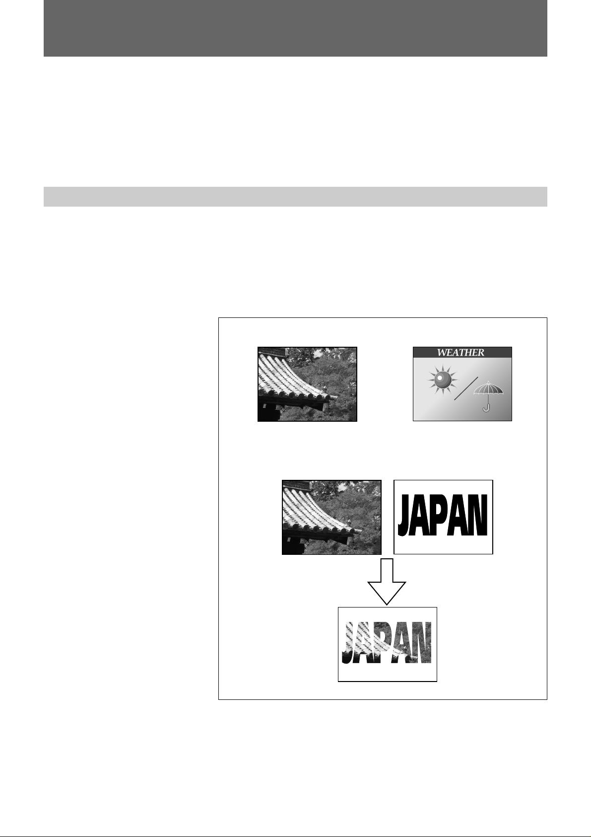
Images to be displayed on the JumboTron screen
The JumboTron system can display the following three types of images:
[a] Video images input from equipment such as a VCR, video camera
and video disc (INPUT 1)
[b] Computer graphics (INPUT 2)
[c] Mixed images of INPUT 1 and INPUT 2
(INPUT 1 images are superimposed on the monochrome area of the
INPUT 2 images.)
[a] INPUT 1 [b] INPUT 2
[c] Mixed images
INPUT 1
Mixed images
INPUT 2
Table of Contents 5
Overview
Overview of the JumboTron System
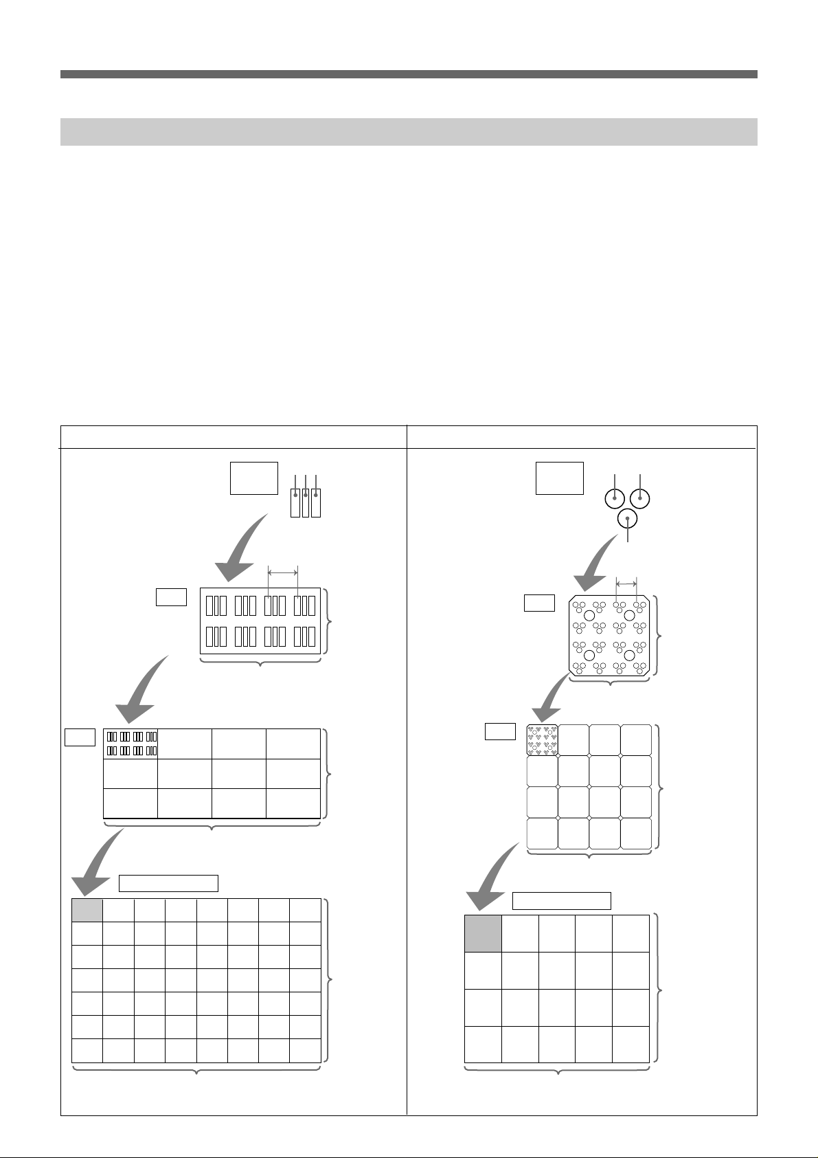
Structure of the JumboTron screen
Two types of the JumboTron screen are available. One is the conventional
CRT type screen in which light emitting bodies of three primary colors (R,
G and B), “Trinilite,” are used as the light emitting element. The other is
the new LED type screen in which light emitting diodes of the three
primary colors are used.
The basic element of the JumboTron screen is an RGB trio (dot).
A “cell” consists of the dots arranged at a certain interval (picture element
pitch) and a “unit (JumboTron display unit)” consists of 12 cells for the
CRT type and 16 cells for the LED type.
There are three unit types, the JTU-35 series (with 35-mm picture element
pitch) and JTU-17 series (with 17.5-mm pitch) of the CRT type, and the
LDU-15 series (with 15-mm pitch) of the LED type. You can configure a
large JumboTron screen by arranging the JumboTron display units
vertically and horizontally to suit various uses or locations.
CRT type (JTU-35 series) LED type
Unit
Cell
4 cells (16 dots)
JumboTron screen
RGB trio
(dot)
4 dots
B R G
Picture element pitch
2 dots
3 cells
(6 dots)
RGB trio
(dot)
Cell
Unit
JumboTron screen
GBR
Picture element pitch
4 dots
4 dots
4 cells (16 dots)
4 cells (16 dots)
NTSC: max. 40 units (160 cells = 640 dots)
PAL: max. 48 units (192 cells = 768 dots)
6 Overview
Overview
NTSC:
max. 80 units
(240 cells =
480 dots)
PAL:
max. 96 units
(288 cells =
576 dots)
NTSC:
max. 30 units
(120 cells =
480 dots)
PAL:
max. 36 units
(144 cells =
576 dots)
NTSC: max. 40 units (160 cells = 640 dots)
PAL: max. 48 units (192 cells = 768 dots)
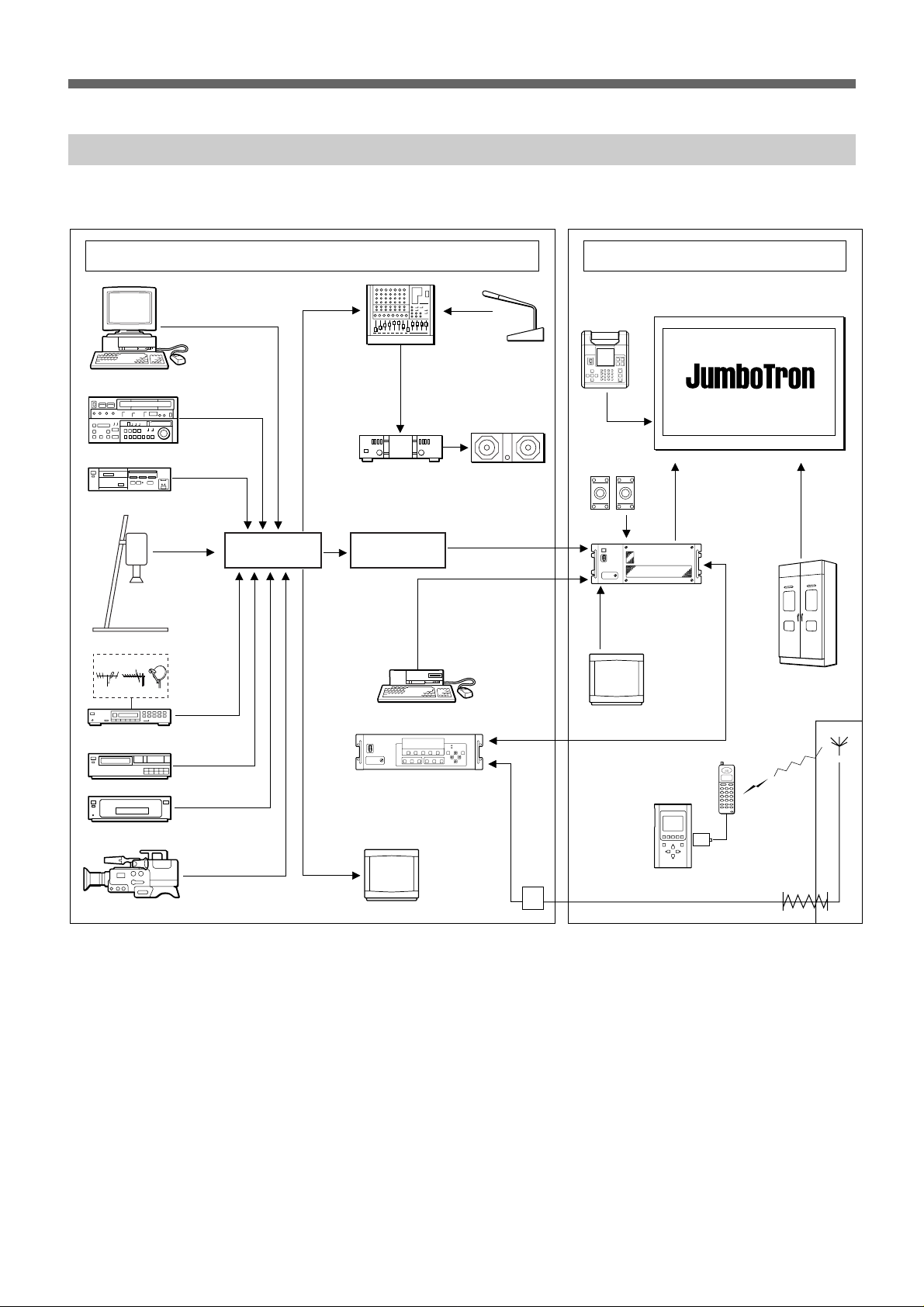
Configuration of the JumboTron system
The following is the suggested configuration of the JumboTron system.
Computer
VCR
Still image player
Video presenter
Control room
AV switcher
Audio mixer
Audio amplifier Speaker system
Frame
synchronizer
Microphone
JME-UA200
unit alignment
controller
JTA-LS200
ABC sensor
unit
JTC-P200 image
control unit (ICU)
Screen site
JumboTron screen
Power source
TV tuner
Video disc player
DVD player
Video camera
Computer
JTC-C200 ICU
controller
Monitor
Modem
Monitor
JME-SA200
screen
alignment
controller
Digital
data
card
Cellular
phone
Public
telephone
line
Table of Contents 7
Overview

Features
JTC-C200 ICU controller
The JTC-C200 ICU controller is the remote controller for the JTC-P200
ICU (Image Control Unit) which controls the images on the JumboTron
screen. Using the ICU controller, you can control the ICU from a control
room at a distance of up to 500 m (1640 feet). The main functions of the
JTC-C200 are as follows:
Turning on/off the ICU and screen
You can turn the ICU and the JumboTron screen on and off.
Selection of screen display mode
You can select the images to be displayed on the JumboTron screen from
among three modes: INPUT 1 (video images), INPUT 2 (computer
graphics) and MIX (mixed images).
Adjustments of the images on the screen
You can adjust the brightness, hue, color and sharpness of the images on
the screen.
The brightness can be automatically adjusted according to the ambient
light with the JTA-LS200 ABC sensor unit. You can also set the desired
brightness level manually, and four brightness levels can be stored in the
memory and recalled at a touch.
JTC-P200 ICU (Image Control Unit)
The JTC-P200 controls the images on the JumboTron screen.
JTA-LS200 ABC sensor unit
The JTA-LS200 ABC (Automatic Brightness Control) sensor unit
connected to the ICU senses the ambient light for the automatic brightness
control.
8 Overview
Overview
Locations and Functions of Parts and Controls
JTC-P200 ICU (Image Control Unit)
Front panel
12 3
45
1 POWER switch
Turns the ICU on/off.
2 Power lamp
Lights when the ICU is turned on.
3 Connector panel
The CONTROL 4 connector is inside. When using the
connector, open the connector panel by loosening the
screw.
4 CONTROL 4 connector (D-sub 15-pin)
This is an RS-422 input port. Connect it to peripheral
equipment such as the JTC-C200 ICU controller for
maintenance.
To remove/attach the front panel
When attaching, insert
the projecting part on the
front panel into the slot
on the ICU.
When removing, loosen the four screws.
5 Front cover
To remove the panel, loosen the four screws.
Table of Contents 9Locations and Functions of Parts and Controls
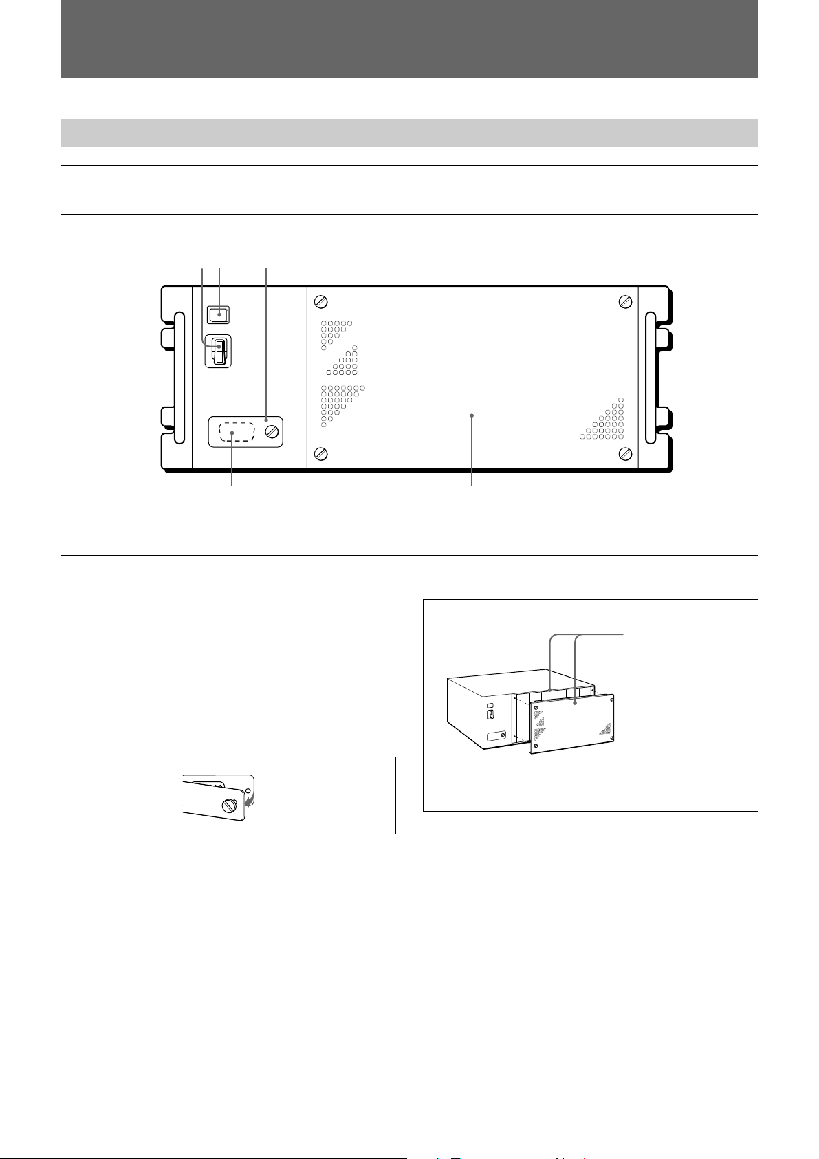
Locations and Functions of Parts and Controls
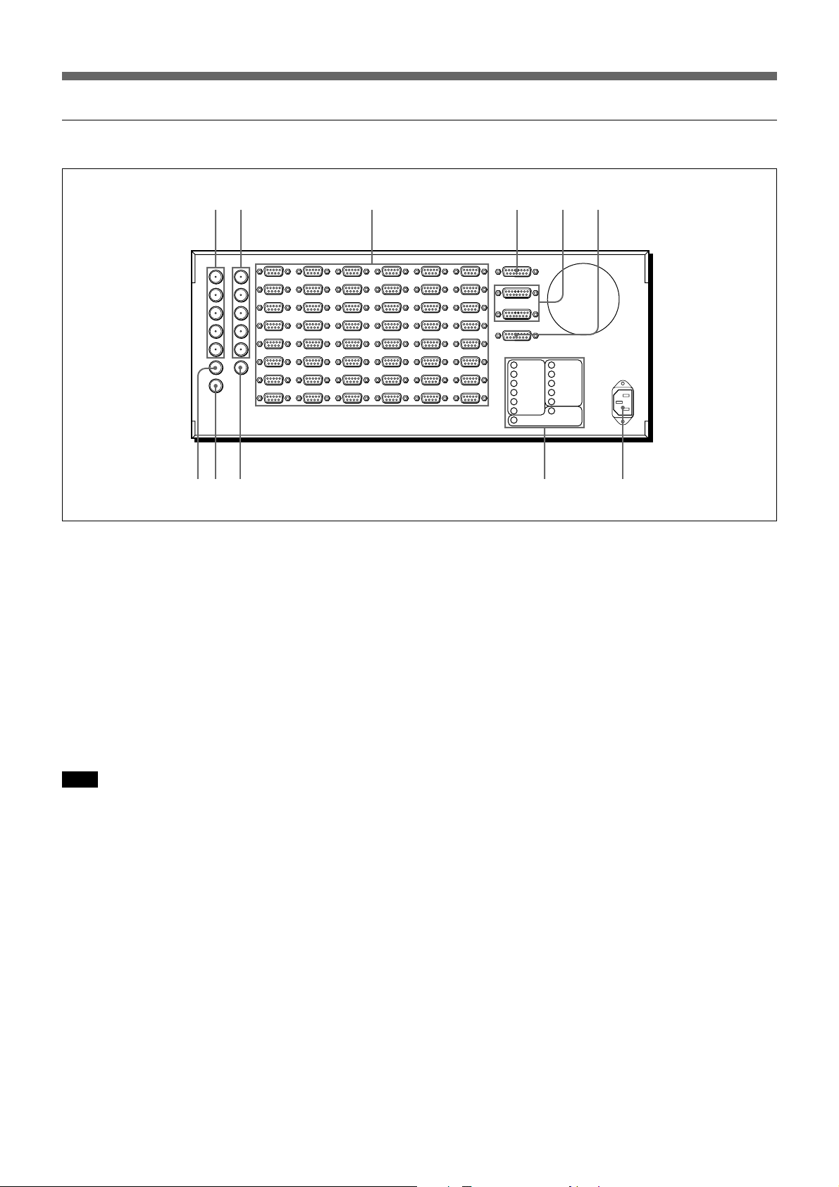
Rear panel
12 3 4 5 6
78 9 0 !¡
1 INPUT 1 (R/R-Y, G/Y, B/B-Y, HD/COMP, VD)
connectors (BNC type)
Connect to the AV switcher to which video equipment,
such as VCRs and video cameras are connected.
2 INPUT 2 (R, G, B, HD/COMP, VD) connectors
(BNC type)
Connect to a computer.
If the computer has a H/V separate sync signal,
connect it to the HD/COMP and VD connectors. If the
computer has a composite sync signal, connect it to the
HD/COMP connector only.
Note
When a computer with a sync signal on G-signal is
connected and an external sync signal is input, the hue
of the images may change. In this case, use the
internal sync signal.
3 SIGNAL OUT connectors (High-density D-sub
15-pin)
Connect to the JumboTron display units using the
JCC-L10/L20/L30 connecting cable (not supplied).
5 CONTROL 2 and CONTROL 3 connectors (Dsub 15-pin)
Connect to the JTC-C200 ICU controller.
6 EXTERNAL CONTROL connector (D-sub 15pin)
Connect to the power distribution panel of the system,
etc.
7 VIDEO IN connector (BNC type)
This is a composite video input connector.
8 VIDEO OUT connector (BNC type)
This is a loop-through output for the VIDEO IN
connector.
9 MONITOR OUT connector (BNC type)
Connect to the video input connector of the video
monitor.
0 Input/output connector indications
Indicates the location of the input/output connectors at
the right end of the rear panel.
4 CONTROL 1/LS (sensor) connector (D-sub 15pin)
Connect to the JTA-LS200 ABC sensor unit using the
specified connecting cable (not supplied). The JTCC200 ICU controller can also be connected to this
connector.
10 Overview
Locations and Functions of Parts and Controls
!¡ AC IN connector
Connect to an AC power supply of 100 - 240 V AC.
Use the supplied AC power cord which fits the AC
outlet in your area.
JTC-C200 ICU controller
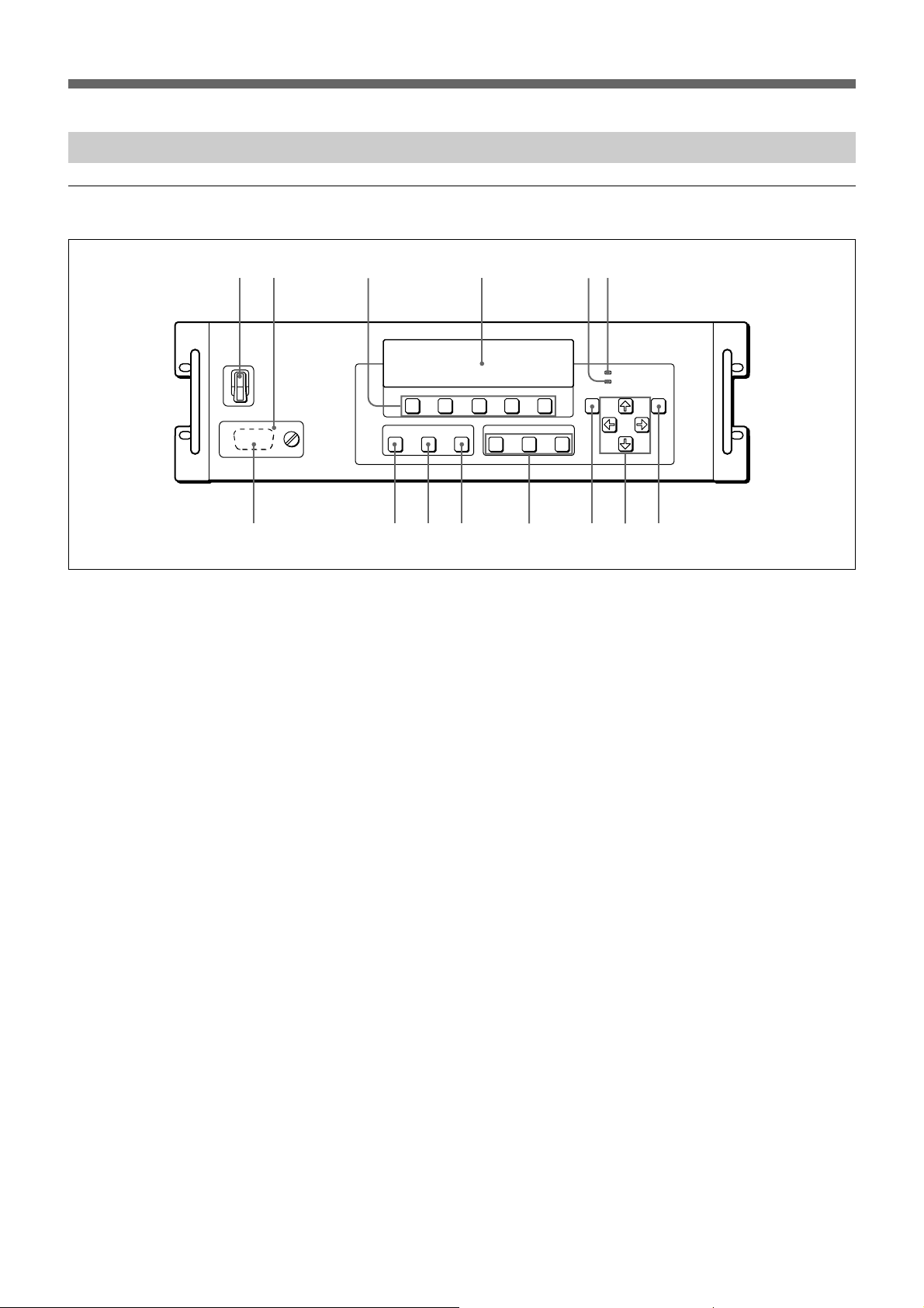
Front panel
12 3 4 56
7 8 9 0 !¡ !™ !£ !¢
1 POWER switch
Turns the ICU controller on/off.
2 Connector panel
The CONTROL 2 connector is inside. When using the
connector, open the connector panel by loosening the
screw.
3 Function buttons (F1 – F5)
The functions of the buttons change with the stage of
the operation. The current functions are indicated in
the display window.
For details, see the chapter “Operation.”
4 Display window
Indicates the menus and the functions of the function
buttons.
5 REMOTE lamp
Currently not used. This is provided for future
extended use.
6 INFORMATION lamp
Lights when a screen abnormality is detected.
7 CONTROL 2 connector (D-sub 15-pin)
Connect to the CONTROL connector of the JMESA200 screen alignment controller for wired control.
8 ICU power button and lamp
Hold down the button for more than a second to turn
the power of the JTC-P200 ICU connected to the
CONTROL 1 connector of the ICU controller on and
off. The button lights when the ICU is turned on.
9 SCREEN power button and lamp
Hold down the button for more than a second to turn
the power of the screen on and off. The button lights
when the screen is turned on.
0 UTILITY button and lamp
Turns the power of the equipment connected to the
EXTERNAL CONTROL connector on and off. The
button lights when the connected equipment is turned
on.
!¡ Display mode buttons and lamps
Selects the image mode to be displayed on the screen.
The selected button lights.
INPUT 1: Displays the images selected via the AV
switcher connected to the INPUT 1 connectors of
the ICU.
INPUT 2: Displays the computer graphics from the
computer connected to the INPUT 2 connectors of
the ICU.
MIX: Displays the video images superimposed on the
monochrome areas of the computer graphics.
!™ MENU button
Displays the menu in the display window or returns to
the menu in the upper directory.
!£ CURSOR ◊/√/ı/∫ buttons
Selects the menu items in the display window or
changes the set values.
!¢ ENTER button
Confirms the selected item and stores the set value.
Locations and Functions of Parts and Controls
Table of Contents 11
 Loading...