

Page 1
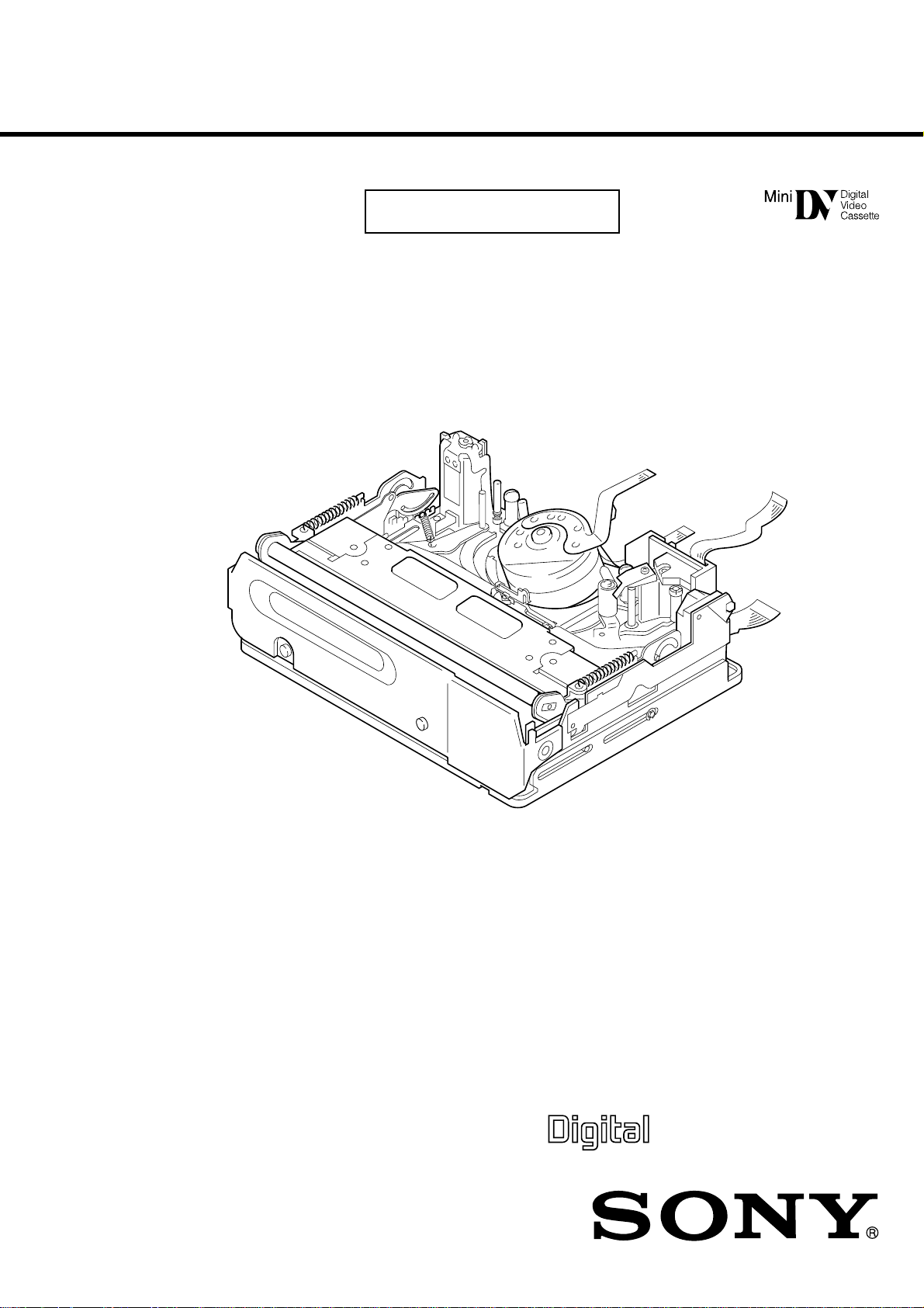
DV MECHANICAL ADJUSTMENT MANUAL VI
Ver 1.0 2000. 3
J MECHANISM
Please use this manual with the service manual of the respective models.
MECHANISM DECK
Page 2

TABLE OF CONTENTS
1. Preparations for Check, Adjustment and
Replacement of Mechanism Block
1-1. Cassette Compartment Assy, Damper Assy ······················· 3
2. Periodic Inspection and Maintenance
2-1. Rotary Drum Cleaning ······················································· 4
2-2. Tape Path System Cleaning ················································ 4
(Refer to Fig. 2-1.)······························································4
2-3. Periodic Inspection List······················································5
2-4. Service Jigs and Tools ························································ 6
2-5. Mode Selector II Operating Procedure······························· 8
4. Tape Path Adjustment
4-1. Adjustment Preparation ···················································· 32
4-2. Tracking Adjustment ························································ 33
4-3. TG3 Guide Adjustment ····················································33
4-4. TG7 Guide Adjustment ····················································34
4-5. Check upon Completion of Adjustment ··························· 34
5. Exploded View
5-1. Cassette Compartment Block Assy, Drum Assy Block ···· 36
5-2. LS Chassis Block Assy····················································· 37
5-3. Mechanism Chassis Block Assy······································· 38
3. Check, Adjustment and Replacement of
Mechanical Parts
3-1. Drum················································································· 12
3-2. L. Motor Holder Block Assy (Loading) and
FP-228 Flexible Wiring Board (DEW Sensor)················· 13
3-3. Retainer Plate Assy, LED Retainer···································14
3-4. Brake-T Block Assy, T-reel Table Assy,
Gooseneck Gear Assy·······················································15
3-5. TG1 Assy, Tension Coil Spring (Tension Regulator) ······· 16
3-6. TG1 FWD Position Adjustment ······································· 17
3-7. FWD Back-tension Adjustment········································ 18
3-8. Reel Torque Check ··························································· 18
3-9. TG3 Guide Zenith Adjustment········································· 18
3-10. TG6 Guide Zenith Adjustment········································· 19
3-11. LS Cam Plate Position Adjustment ·································· 19
3-12. LS Chassis Block Assy, LS Guide Retainer····················· 20
3-13. LS Cam Plate, Tension Coil Spring (Brake-S), Brake-S,
Torsion Coil Spring (Brake Arm), Cassette Position Set-S,
Brake-S Driving Arm Assy··············································· 21
3-14. TG7 Block Assy, Torsion Coil Spring
(TG7 Return, Pinch Return), Pinch Arm Assy ················· 22
3-15. Layout Diagram of FP-102 Flexible Wiring Board·········· 23
3-16. TG1 Cam Slider, LS Arm, LS Roller,
Mode Gear Assy, LS Guide Roller··································· 24
3-17. Guide Rail········································································· 25
3-18. Gear Cover B, GL Driving Gear ······································ 26
3-19. Drum Base Block Assy, Coaster-S Block Assy,
Coaster-T Block Assy·······················································27
3-20. DC Motor (Capstan), Conversion Gear, Relay Gear ········ 28
3-21. Gear Cover C, Pinch Driving Arm Assy, Cam Gear B····· 29
3-22. Gear Cover A, FP-100 Flexible Wiring Board ················· 30
3-23. Deceleration Gear, Mode Gear Assy,
FP-100 Flexible Wiring Board, Cam Gear A ··················· 31
6. Printed Wiring Boards and
Schematic Diagrams ·············································· 39
7. Electrical Parts List················································· 41
— 2 —
Page 3
1. Preparations for Check, Adjustment and Replacement of Mechanism Block
Removal method of
damper assy
1 Claw
1 Claw
Damper assy
Holder arm
Damper shaft
Holder arm
While pressing
toward the inside
Cassette compartment
slide shaft
Cassette compartment
slide shaft
D Groove
Holder arm
LS chassis block assy
LS frame pivots
(two pivots in the right and left)
LS chassis block assy
LS chassis block assy
Cassette compartment
block assy
D Groove
F Notch
While pressing
toward the inside
Cassette compartment
block assy
LS frame
2 Two screws (M1.4 × 2)
Dowel
Slot of damper arm
A
C
B
E
E
* Be careful not to
deform here.
* Be careful not to
deform here.
LS chassis block assy
LS frame
• Refer to the “DISASSEMBLY” section of the SERVICE MANUAL of the respective models for details of removing cabinets and
printed wiring boards.
• When making any adjustment to a mechanism or r eplacing mechanical parts, be sure to use the Mode Selector II and select the appropriate
status of the mechanical deck such that the mechanical status is suitable for the desired work. Refer to section “2-5. Mode Selector II”
for details on how to enter the mode shown in a rectangle [ ] mode in subsequent paragraphs of this manual.
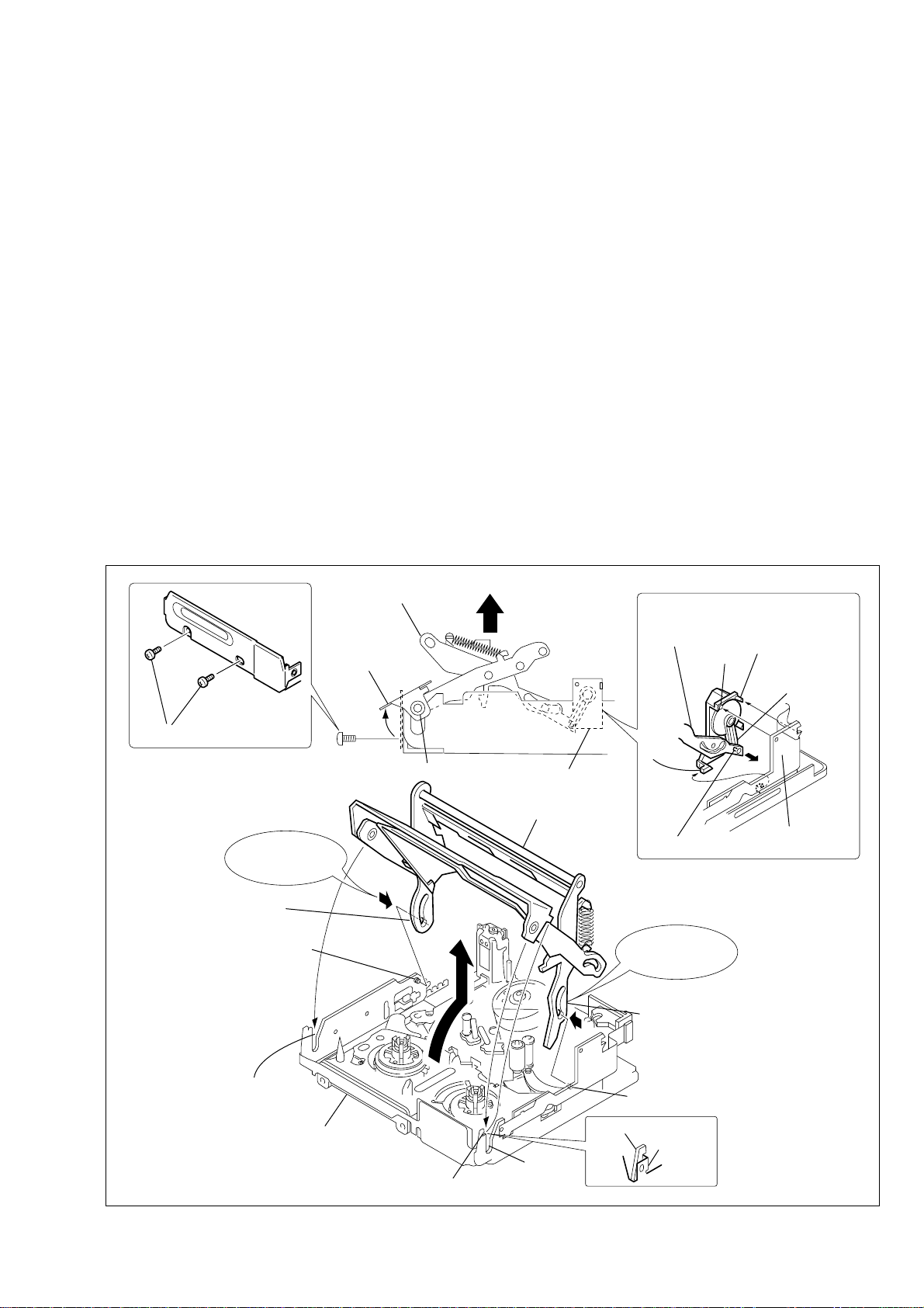
1-1. Cassette Compartment Assy, Damper Assy
1. Removal Procedure
1) Set the [EJ] mode.
2) When the cassette compartment moves up in the direction of
the arrow B, establish the [ULE] mode.
3 Release the two claws 1 and dowel of the damper assy and
remove the damper assy.
4) Remove the shaft of the holder arm from the damper arm.
5) Remove the two screws (M1.4 × 2) 2.
6) Lift up the LS frame in the direction of the arrow C.
7) Lift up the cassette compartment block assy in the direction of
the arrow A. While pushing the holder arm in the direction of
the inside arrow E, remove the cassette compartment block
assy.
2. Attachment procedure
1) Set the [ULE] mode.
2) Attach the holder arm of the cassette compartment block assy
to the cassette compartment slide shaft on both sides of the LS
chassis block assy from inside.
3) Install the LS frame pivot into the groov e D of the LS chassis.
Drop down the LS frame in the direction opposite to C.
4) Hook the LS frame T -side bent portion on the LS chassis notch
F.
5) Attach the LS frame with two screws (M1.4 × 2) 2.
Tightening torque: 0.054 ± 0.01 N•m (0.6 kg•cm).
6) While inserting the damper shaft of the cassette compartment
block assy into slot of the damper arm, engage the two claws
1 with the notch of the LS chassis block assy, and fix the
dowel to the corresponding hole of the LS chassis block assy
respectively.
Note: Check that the two claws 1 and dowel do not come off.
Fig. 1-1
— 3 —
Page 4
2. Periodic Inspection and Maintenance
t
• Be sure to perform the following maintenance and inspection so
that the machine delivers its full performance and functions, and
to protect the machine and tape. Also, perform the following
maintenance items after completing the repair work, regardless
of the number of hours the machine has been operated by the
user.
2-1. Rotary Drum Cleaning
1) Press a wiping cloth (Ref. No. J-2) moistened with cleaning
fluid (Ref. No. J-1) lightly against the rotary drum. Rotate the
upper drum with a super-fine applicator slowly in the counter clockwise direction to clean the rotary drum.
Caution: Never rotate the rotary drum by turning on the main power of
the motor or rotate it in the clockwise direction. Never move the
cloth vertically against the head tip, as this will surely damage
the video head; the video head must not be cleaned by any other
different methods.
TG2
TG1
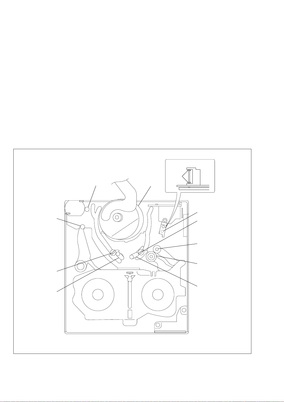
2-2. Tape Path System Cleaning
(Refer to Fig. 2-1.)
1) Set the EJECT state. Clean the tape running path (TG-1, -2, 3, -4, -5, -6 and -7, pinch roller and capstan shaft) and lower
drum with a super-fine applicator (Ref. J-3) moistened with
cleaning fluid.
Note 1: Be careful not to allow oil or grease of the various link mechanisms
to get on the super-fine applicator (Ref. J-3).
Note 2: Once the super-fine applicator has been moistened with alcohol,
do not use it to clean other mechanical parts such as the tape guide.
However, the pinch roller is cleaned with alcohol.
Note 3: When cleaning the capstan shaft, be carefull not to move the oil
seal. If the oil seal is moved, oil will leak.
Capstan shaft cleaning
Oil seal
Drum
Capstan shaf
TG6
TG3
TG4
TG7
Pinch roller
TG5
Fig. 2-1
— 4 —
Page 5
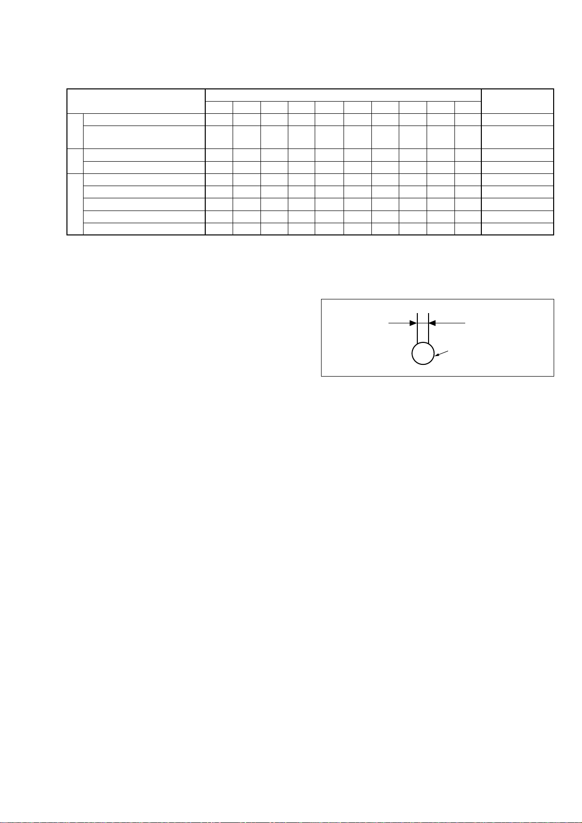
2-3. Periodic Inspection List
r
Maintenance and inspection item
Tape running surface cleaning
Rotary drum cleaning and
degaussing
Capstan bearing
Loading motor
Drive
mechanism
Abnormal sound
Back-tension measurement
Brake system
Brake system
FWD/RVS torque measurement
Performance check
Note 1: When the machine is overhauled, replace the parts referring to the
Note 2: Grease
above list.
• Be sure to use the specified grease only. (If grease of different
viscosity is used, it can cause various troubles.)
• The grease used for bearings must not contain any dust or other
matter, otherwise excessive abr asion and seizure of the bearing
could occur.
• A drop of grease means the amount of grease as shown in the
illustration, which is the amount that is attracted to the tip of a
rod of 2 mm diameter.
• FLOIL grease (SG-941): Part No. 7-662-001-39
500
a
a
—
—
✩
—
—
—
—
1000
a
a
✩
✩
✩
✩
✩
✩
✩
1500
a
a
—
—
✩
—
—
—
—
Operating hours (H)
2000
2500
3000
a
a
a
a
a
a
✩
—
✩
✩
—
✩
✩
✩
✩
✩
—
✩
✩
—
✩
✩
—
✩
✩
—
✩
3500
a
a
—
—
✩
—
—
—
—
4000
a
a
✩
✩
✩
✩
✩
✩
✩
4500
a
a
—
—
✩
—
—
—
—
2 mm diamete
Fig. 2-2
5000
a
a
Remarks
Be careful not to attach oil
Be careful not to attach oil
✩
✩
✩
✩
✩
✩
✩
a: Cleaning, ✩: Check
Grease
— 5 —
Page 6

2-4. Service Jigs and Tools
Ref. No.
J-1
Cleaning fluid
J-2
Wiping cloth
Super-fine applicator
J-3
(made by Nippon Applicator (P752D))
J-4
Mirror (small oval type)
J-5
Tracking tape (XH2-1) (NTSC, PAL)
J-6
Mini DV torque cassette
J-7
TG1 adjustment jig (FWD position adjustment)
J-8
TG1 FWD adjustment screwdriver
J-9
Dummy drum (for TG36) (J mechanism)
J-10
TG36 gauge
J-11
Torque screwdriver
J-12
Tape path screwdriver
Adjustment remote commander
J-13
(RM-95 upgraded) * Note 1
J-14
Mode Selector II
J-15
Mode Selector II conversion board (J)
Mode Selector II ROM (supporting J mechanism)
J-16
* Note 2
Other required equipment: Oscilloscope
Note 1: If the microprocessor in the adjustment remote commander is not
the new one (UPD7503G-C56-12), the pages cannot be switched.
In this case, replace it with the new microprocessor (8-759-148-
35).
Name
Y-2031-001-0
7-741-900-53
J-6080-840-A
8-967-997-01
J-6082-360-A
J-6082-492-A
J-6082-364-A
J-6082-490-A
J-6082-491-A
J-9049-330-A
J-6082-026-A
J-6082-053-B
J-6082-282-B
J-6082-493-A
J-6082-314-E
Part code
—
Jig inscription
GD-2038
Used for
Tape path
Tape path
For TG1 FWD position adjustment
For tape path adjustment
General adjustment (ROM version 1.7)
ROM for Mode Selector II
Note 2: This is the ROM used for upgrading the version of Mode Selector
II to enable it to be used for the J mechanism.
— 6 —
Page 7
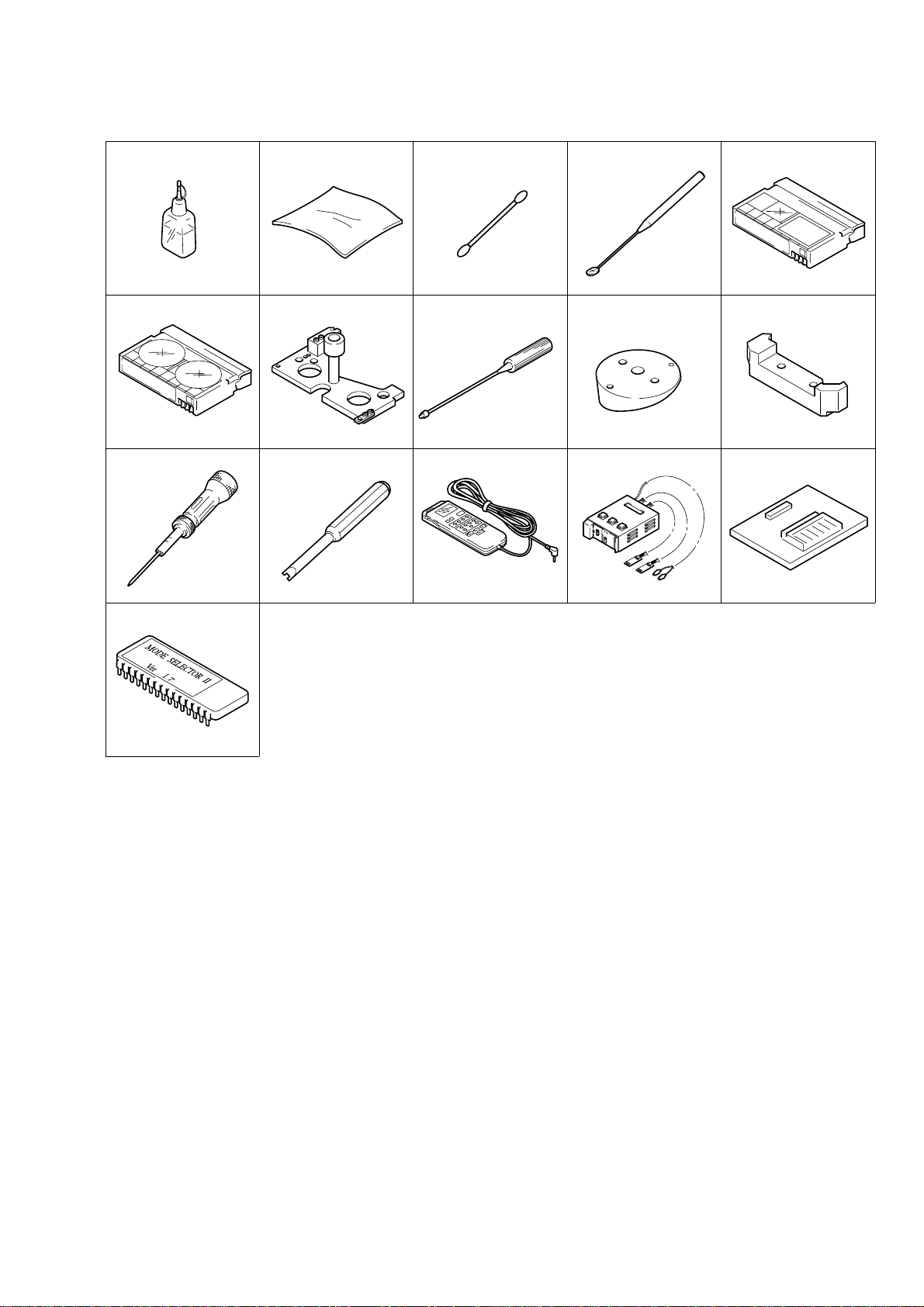
J-1 J-2 J-3 J-4 J-5
J-6 J-7 J-8 J-9 J-10
J-11 J-12 J-13 J-14 J-15
J-16
Fig. 2-3
— 7 —
Page 8
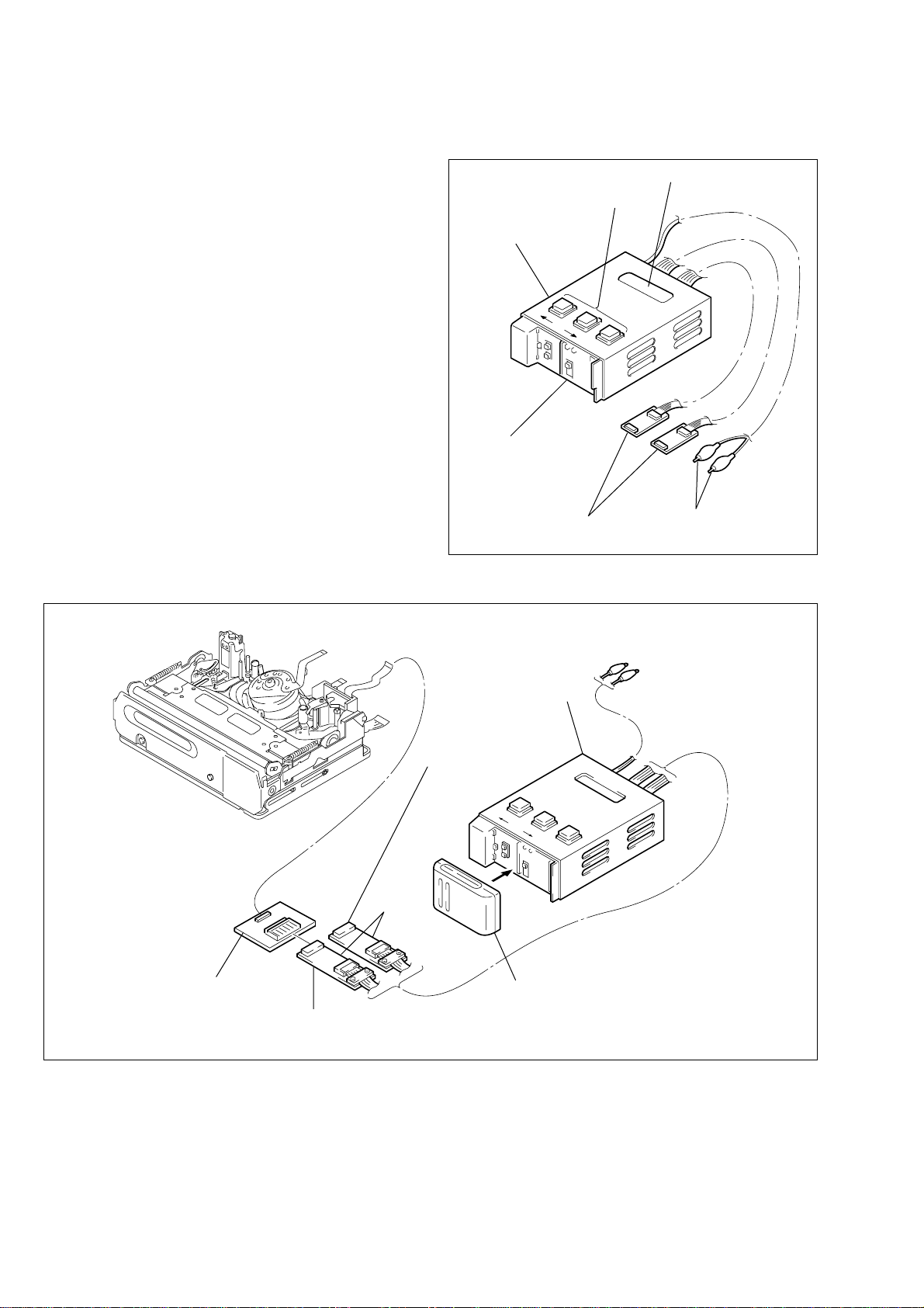
2-5. Mode Selector II Operating Procedure
2-5-1. Introduction
The Mode Selector II is a mechanism drive tool that assists
maintenance work of the various mechanism decks. It has the
following functions.
1. Manual Test
In this mode, the motor of the mechanism deck is powered only
during the period while the switch is turned on manually. Using the
Manual Test, the operator can freely control the motor of the
mechanism deck.
2. Step Test
In this mode, the motor of the mechanism deck is kept turned on
until the mechanical status is changed from the present mechanical
status that is obtained from the sensor information. The Step T est is
used to confirm a series of movements of the mechanism deck.
LCD display screen
Selector button
Mode Selector II
(Ref. No. J-14)
RVS
FF
SEL
3. Auto Test
The Mode Selector II stores the status transition table in its memory
as data indicating the respective modes of the mechanism deck.
The status transition table can be used to confirm whether a
mechanism deck is operating normally or has abnormality from a
series of movements of a mechanism deck. If an abnormal status
transition is detected during operation, the “NG” indication appears
and the mechanism stops moving.
Mode Selector II (J-6082-282-B) connection diagram
J mechanism
External battery is
connected here as
a power supply
Relay board
(already connected)
Mode Selector II
Connector (black) 6-pin
(not used in J mechanism)
Alligator clip
Fig. 2-4
Alligator clip
(not used in J mechanism)
Mode Selector II
conversion board (J)
(Ref. No. J-15)
Relay board
Battery such as NP-55, NP-77
(power supply)
Connector (white) 6-pin
Fig. 2-5
— 8 —
Page 9
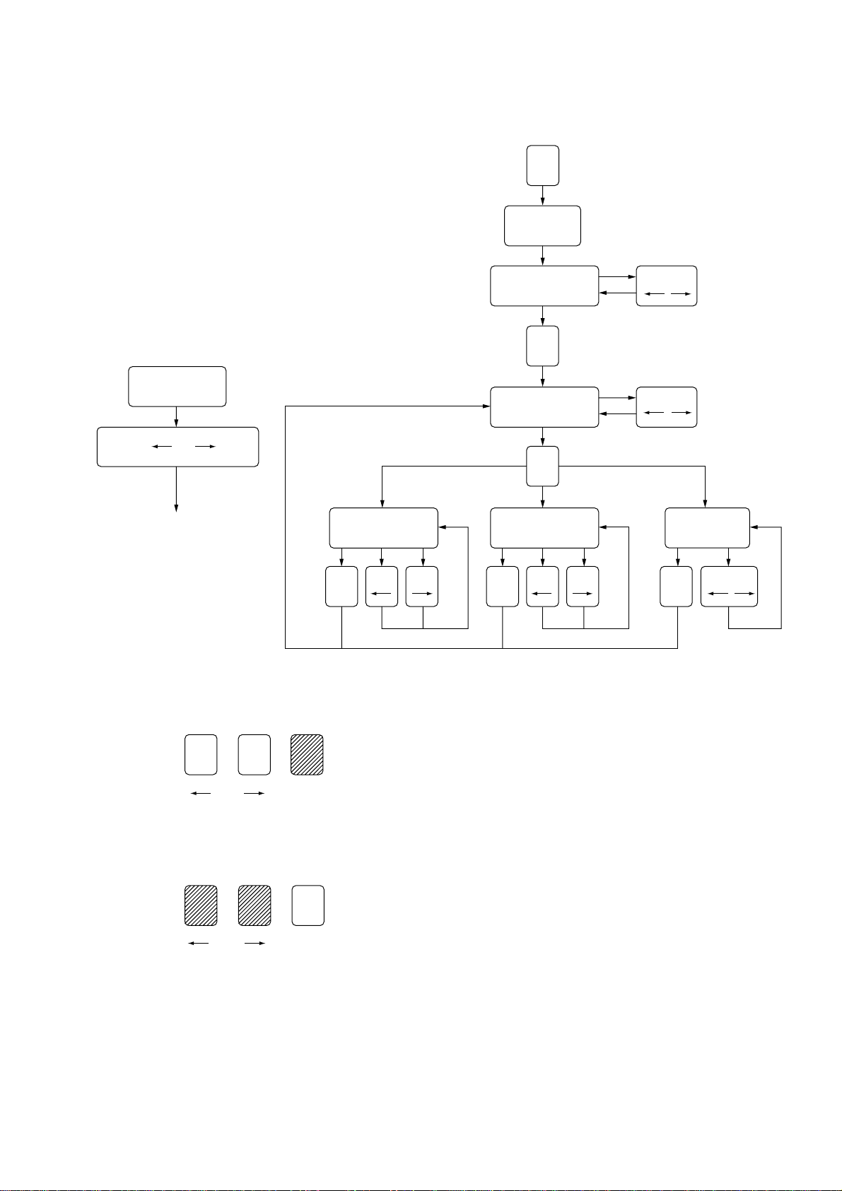
2-5-2. Operation
SEL
SEL
SEL
STEP TEST
MANUAL TEST
AUT O TEST
POWER ON
MECHA SELECT
MODE SELECT
From any status
Press RVS and FF for
2 sec. simultaneously
Main power is
turned off
RVS, FF
RVS, FF
RVS, FFSELRVS FFSELRVS FFSEL
1. Operation Flow Chart
Note: The ROM in the Mode Selector II supports the J mechanism.
2. Mode Selector II Power On
Turn on the main power of the Mode Selector II as follows.
Press the SEL button.
3. Mode Selector II Power Off
Turn off the main power of the Mode Selector II as follows.
Press the RVS and FF buttons at the same time for 2 seconds or
longer while the power is on.
RVS FF SEL
RVS FF SEL
— 9 —
Page 10
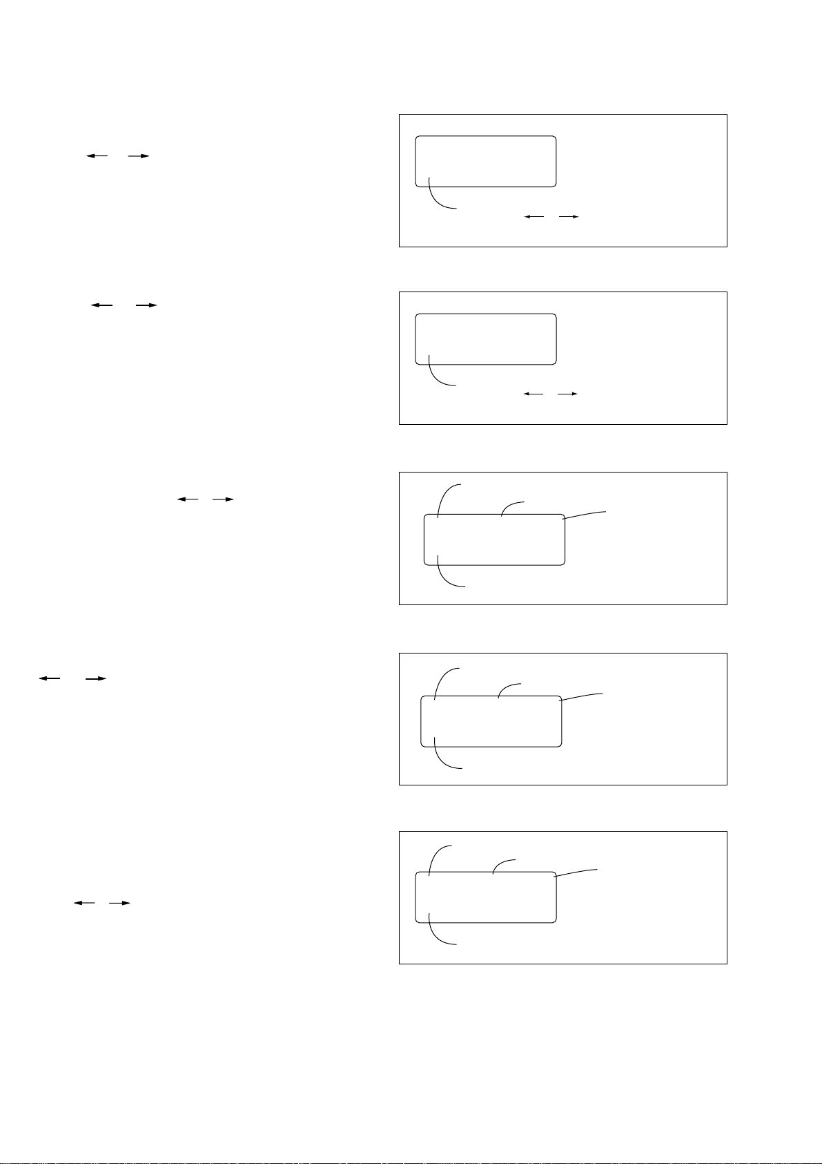
4. Mecha Select
)
)
)
When the main power is turned on, the MECHA SELECT display
appears on the LCD screen. Select the desired mechanism name
using the R VS and FF buttons. Selection is complete when the SEL
button is pressed. (Fig. A shows the J mechanism.)
5. Test Type Select
Using the RVS and FF buttons, select a desired test type from the
three types of “MANUAL”, “STEP” and “AUTO”. Selection is
complete when the SEL button is pressed.
6. Manual Test
In this test, the motor of the mechanism deck is turned on only
during the period while the RVS or FF button is pressed manually.
MECHA SELECT
J
Pressing the RVS or FF button
changes the mechanism name.
Fig. a
TEST TYPE SELECT
MANUAL
Pressing the RVS or FF button cycles
among MANUAL, STEP, AUTO in this order.
Fig. b
Mechanism name
Present mode
Motor ON/OFF
J MANUAL OFF
STATUS
7. Step Test
In this test, the direction of motor movement is determined by the
RVS and FF buttons. The motor of the mechanism deck is kept
turned on until the mechanical status is changed from the present
mechanical status that is obtained from the sensor information.
8. Auto Test
In this test, the mechanism deck is tested as to whether it performs
a series of movements correctly in accordance with the operation
sequence that is memorized earlier for each type of deck, by checking
the output signals from sensors with the stored memory. Turning
on the RVS or FF button performs the same operation.
Present status of sensor appears. (example: EJ
Fig. c
Mechanism name
Present mode
Motor ON/OFF
J STEP OFF
STATUS
Present status of sensor appears. (example: EJ
Fig. d
Mechanism name
Present mode
Motor ON/OFF
J AUTO OFF
STATUS
Present status of sensor appears. (example: EJ
Fig. e
— 10 —
Page 11
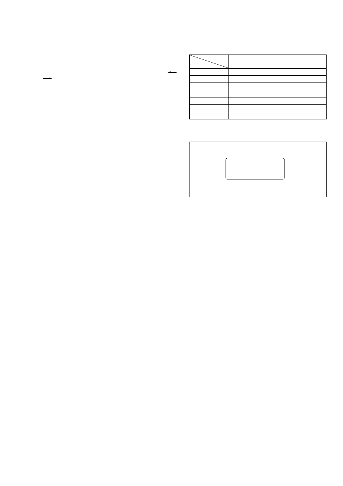
2-5-3. Mechanism Status (Position) Transition Table Using Mode Selector II
After selecting a mechanism deck, select either the MANUAL or
STEP test (not AUTO) using the Mode Selector II. The desired
mechanism status (position) can be specified by pressing the RVS
or FF button. (The selected status appears on STATUS.)
EJyULEySRyGLySTOPyRP
2-5-4. Battery Alarm Indication
When the level of the battery used to supply power to this system
decreases, this display appears asynchronously . When this happens,
all operations are disabled and the battery must be replaced.
MD name
Code
ABC
001
101
100
110
010
011
J Mechanism
1
EJ
2
ULE
3
SR
4
GL
5
STOP
6
RP
BATT DOWN
CHANGE PLEASE
Fig. f
— 11 —
Page 12
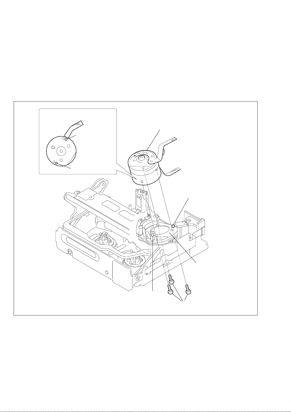
3. Check, Adjustment and Replacement of Mechanical Parts
y
3-1. Drum
1. Removal procedure
1) Loosen the three screws (M1.4 × 2) 1 fixing the drum and
remove the drum.
Drum (rear view)
Slot (reference hole A)
Hole (reference hole B)
2. Attachment procedure
1) Align the two reference holes A and B on the rear of the drum
with the position setting reference pins A and B of the drum
base assy.
2) Install the drum with the three screws (M1.4 × 2) 1 and tighten
the screws in order from A, then B and finally C.
Tightening torque: 0.059 ± 0.01 N•m (0.6 kg•cm)
3) Clean the drum referring to section 2-1.
4) Perform the tape path adjustment. (Refer to section 4, “Tape
Path Adjustment”.)
Drum
Reference pin B
Fig.3-1
Reference pin A
Drum base block ass
C
A
B
1 Three screws (M1.4 × 2)
— 12 —
Page 13
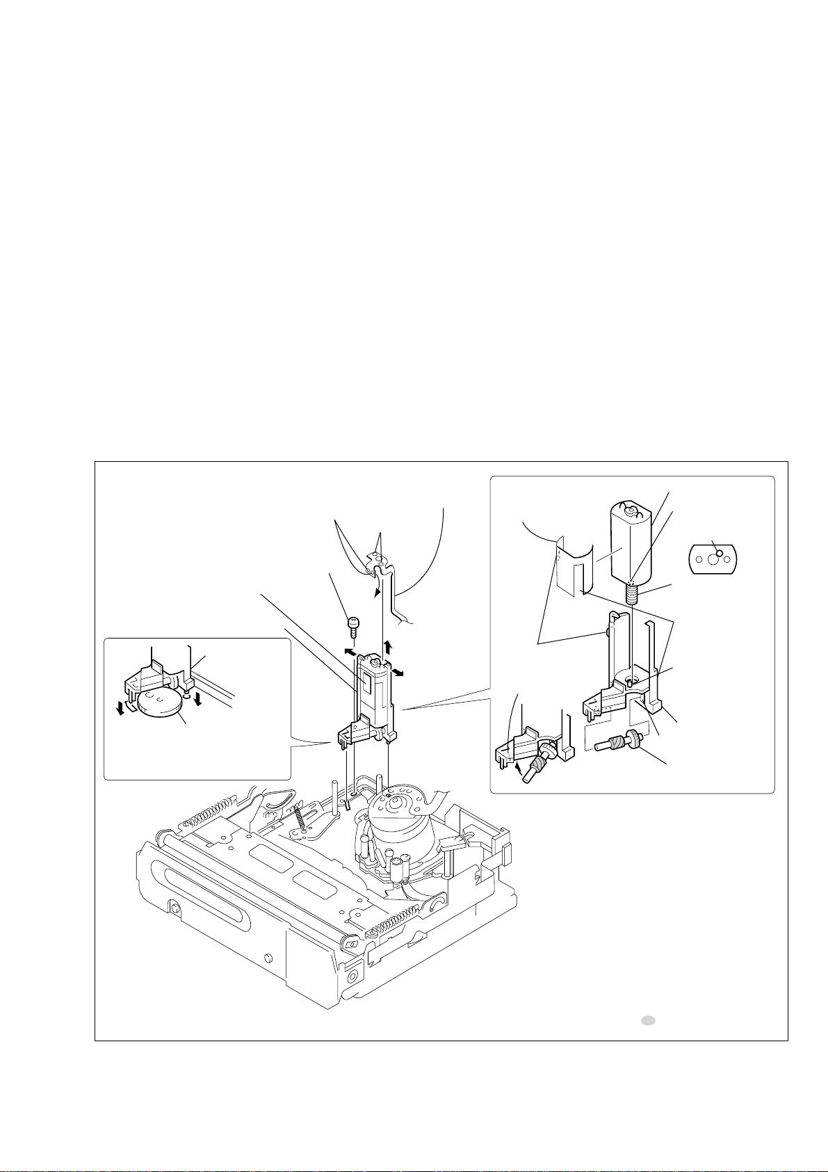
3-2. L. Motor Holder Block Assy (Loading) and
1 Screw (M1.4 × 2.5)
2 Remove
soldering.
3 Remove soldering.
L motor holder block assy
FP-100 flexible wiring board
L motor block assy (loading)
Motor holder
Pin
(The pin must enter
into the polarity
marking hole.)
FP-228 flexible wiring board
(DEW sensor)
Worm shaft
Motor shield
L motor holder
block assy
Deceleration gear
Align the chassis's two square holes
with the round holes.
Note: Be careful not to override.
C Polarity
marking hold
Polarity marking hold
Motor worm
When attaching it,
align the notch with
the dowel.
When attaching it,
align the notch with
the protrusion.
A
A
B
E Claw
D
When attaching it, coat the hatched portion with grease.
FP-228 Flexible Wiring Board (DEW Sensor)
1. Removal procedure
1) Remove soldering 2 from the L motor holder block assy
(loading). Remove the FP-100 flexible wiring board.
2) Remove soldering 3 from the flexible wiring board FP-100.
Remove the FP-228 flexible wiring board (DEW sensor).
Note: Since the FP-228 flexible wiring board (DEW sensor) is attached to
the motor shield by adhesive agent, be careful not to break the flexible
board when removing soldering.
3) Remove the screw (M1.4 × 2.5) 1.
4) Remove the L motor holder block assy.
5) Unlock the claw E and remove the worm shaft.
6) Remove the motor shield.
7) Unlock the two claws A of the motor holder. Remove the L
motor block assy (loading) in the direction of B.
Note: Be careful not to touch the DEW sensor.
2. Attachment procedure
1) Check the direction of the polarity marking C of the L motor
block assy (loading). Attach the L motor block assy (loading)
to the motor holder so that the L motor block assy (loading)
faces the worm shaft side.
2) While aligning the slot and dowel with the motor shield, attach
the motor holder to the motor holder.
3) Apply grease (1/2 drop) between the worm shaft gear and gear
tooth.
4) While the worm gear is engaged with the worm shaft gear,
insert the worm shaft tip into the groove B and fix the worm
shaft under the claw E.
5) While aligning the chassis’s two square holes with the two round
holes, attach the motor holder block assy with the screw (M1.4
× 2.5) 1.
Tightening torque: 0.059 ± 0.01 N•m (0.6 kg•cm)
6) Connect FP-228 (DEW sensor) to the FP-100 flexible wiring
board by soldering. Attach the DEW sensor to the motor shield.
7) Connect the FP-100 flexible wiring board to the motor holder
block assy (loading) by soldering.
Fig. 3-2
— 13 —
Page 14
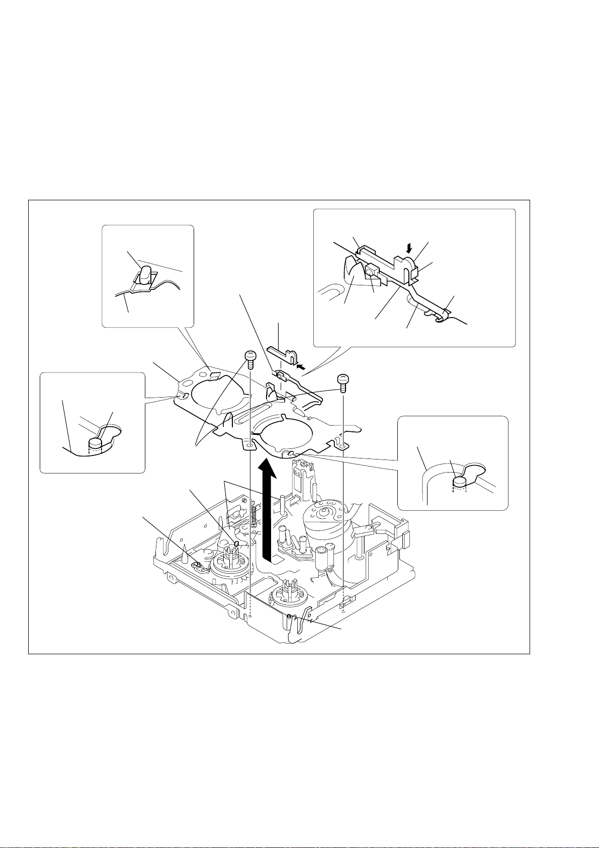
3-3. Retainer Plate Assy, LED Retainer
1. Removal procedure
1) While pressing the claw of the LED retainer in the direction of
the arrow A, remove the LED retainer.
2) Remove the LED portion 2 of the FP-102 flexible wiring
board.
3) Remove the two screws (M1.4 × 1.4) 1.
4) In order to remove the retainer plate assy, because it is hooked
with shaft A, shaft B and shaft C, remove the retainer plate
assy while moving it in the direction of the arrow B.
Notch A
Claw on top of TG1 assy
2 FP-102 flexible wiring board
Shaft A
Retainer plate assy
Retainer plate assy
Notch B
Retainer plate assy
Brake-S pivot shaft
LED retainer
2. Attachment procedure
1) Hook shaft A, shaft B and shaft C on notch A, notch B and
notch C of the retainer plate assy in this order.
2) Attach the retainer plate assy with two screws (M1.4 × 1.4) 1.
Tightening torque: 0.059 ± 0.01 N•m (0.6 kg•cm)
3) Route the FP-102 flexible wiring board as shown and install
the LED into the prism as shown.
4) Hook the LED retainer on D, attach it to E and fix them.
Routing the FP-102 flexible wiring board
D
LED
Prism
Flexible board is routed
under the LED retainer.
A
LED retainer
E
Route it so that the
flexible board is placed
above the LED retainer.
2 FP-102 flexible wiring board
Shaft B
Shaft B
1 T wo screws
(M1.4 × 1.4)
TG1 ASSY
Shaft A
B
Fig. 3-3
Notch C
Retainer plate assy
Brake-T pivot shaft
Shaft C
Shaft C
— 14 —
Page 15
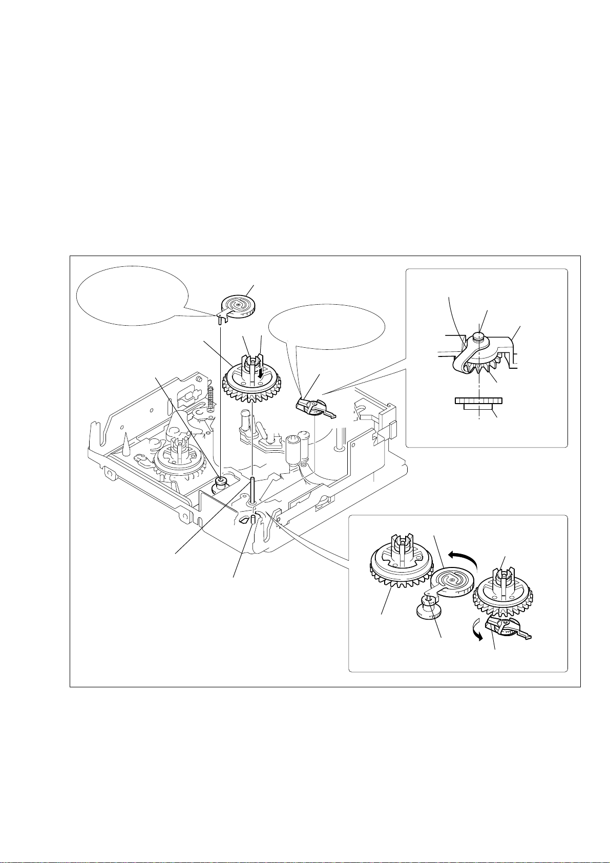
3-4. Brake-T Block Assy, T-reel Table Assy, Gooseneck Gear Assy
1. Removal procedure
1) Remove the brake-T block assy from the brake-T pivot shaft.
2) While pressing the reel claw retainer A of the T-reel table assy
down in the direction of B, remove the reel claw C.
3) Remove the gooseneck assy from the relay gear shaft.
Note: Be careful not to break the reel claw.
When attaching it,
bend the gooseneck gear
assy to the S-reel table
assy side.
T-reel table assy
Relay gear shaft
Gooseneck gear assy
Move the brake-T
counter-clockwise so that
A
C
the T-brake is freed.
B
Brake-T block assy
2. Attachment procedure
1) Insert the gooseneck gear assy into the center hole of the relay
gear shaft. Bend the gooseneck gear assy to the S-reel table
assy side.
2) Attach the brake-T block assy to the brake-T pivot shaft D.
3) Move the brake-T counter-clockwise so that T-brake is freed.
While pressing down the reel claw of the T-reel assy, fix the Treel to the reel shaft-T by rotating the reel.
4) Check that the brake spring-T works correctly by rotating the
T-reel table assy 30 degrees in the clockwise and counterclockwise directions.
Note: The retainer on top of the brake spring-T must be hooked on the
brake-T pivot shaft D and moved down to the groove.
Brake-T block assy
Brake spring-T
D Brake-T pivot shaft
Brake-T
Brake gear-T
E Reel shaft-T
D Brake-T pivot shaft
Brake gear-T must be positioned so that
its steps face downward.
Gooseneck gear assy
T-reel table assy
S-reel table assy
Relay gear shaft
Move the brake-T counter-clockwise
so that the T-brake is freed.
Fig. 3-4
— 15 —
Page 16
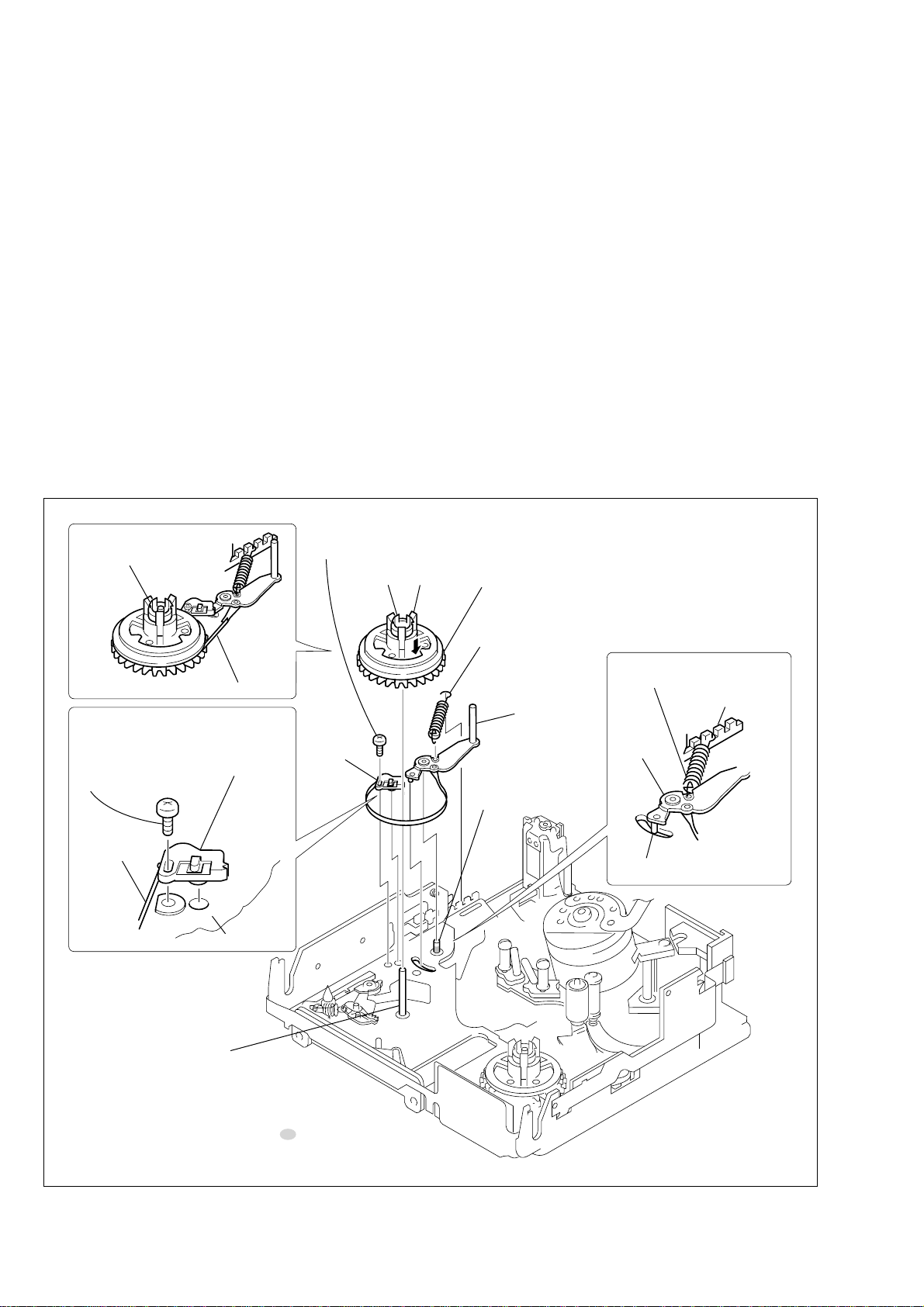
3-5. TG1 Assy, Tension Coil Spring (Tension Regulator)
1. Removal procedure
1) Remove the screw (M1.4 × 2.5) 1.
2) Remove the tension coil spring.
3) Remove the TG1 assy tension regulator band.
4) Remove the (FWD) adjustment plate from the S-reel table.
Place it between the T-reel table assy and pinch arm assy.
5) While pressing down the reel claw retainer A of the S-reel
table assy in the direction of B, remove the reel claw C.
Note 1: Be careful not to deform the tension regulator band.
Note 2: Be careful that grease does not attach to the tension regulator band.
S-reel table assy
1 Screw (M1.4 × 2.5)
CA
2. Attachment procedure
1) Coat the root and its surroundings on TG1 piv ot shaft A with
grease (1/4 drop). (Strictly observe the coating position and
specified amount of grease.)
2) Attach the S-reel table assy to the reel shaft-S.
3) Attach the TG1 assy to the TG1 pivot shaft A. Note that the
TG1 drive shaft has entered the groove of the LS block assy at
this moment.
4) Wrap the tension regulator band around the S-reel table assy.
Fix it with the screw (M1.4 × 2.5) 1 while ensuring that
direction of the (FWD) adjustment plate is correct as shown.
5) Hook the tension coil spring 2 on the TG1 assy and on the LS
chassis block assy.
6) Clean the tip of the TG1 pivot shaft with a super -fine applicator
(Ref. J-3) moistened with cleaning fluid.
7) Perform the (FWD) position adjustment referring to section 3-
6.
8) Perform the FWD back-tension adjustment referring to section
3-7.
9) Perform the reel torque check referring to section 3-8.
S-reel table assy
Tension regulator band
Confirm that the direction
of the (FWD) adjustment plate is
correct.
1 Screw (M1.4 × 2.5)
Tension
regulator band
Correct direction
of attachment
LS chassis
block assy
Reel shaft-S
(FWD)
adjustment
plate
B
2Tension coil spring (tension regulator)
2Tension coil spring
(tension regulator)
LS chassis block assy
TG1 Assy
TG1 Assy
A TG1 pivot shaft
Be sure that the arm shaft has
entered the groove.
When attaching it, coat the hatched portion with grease.
FLOIL grease (SG-941): Part No. 7-662-001-39
Fig. 3-5
— 16 —
Page 17
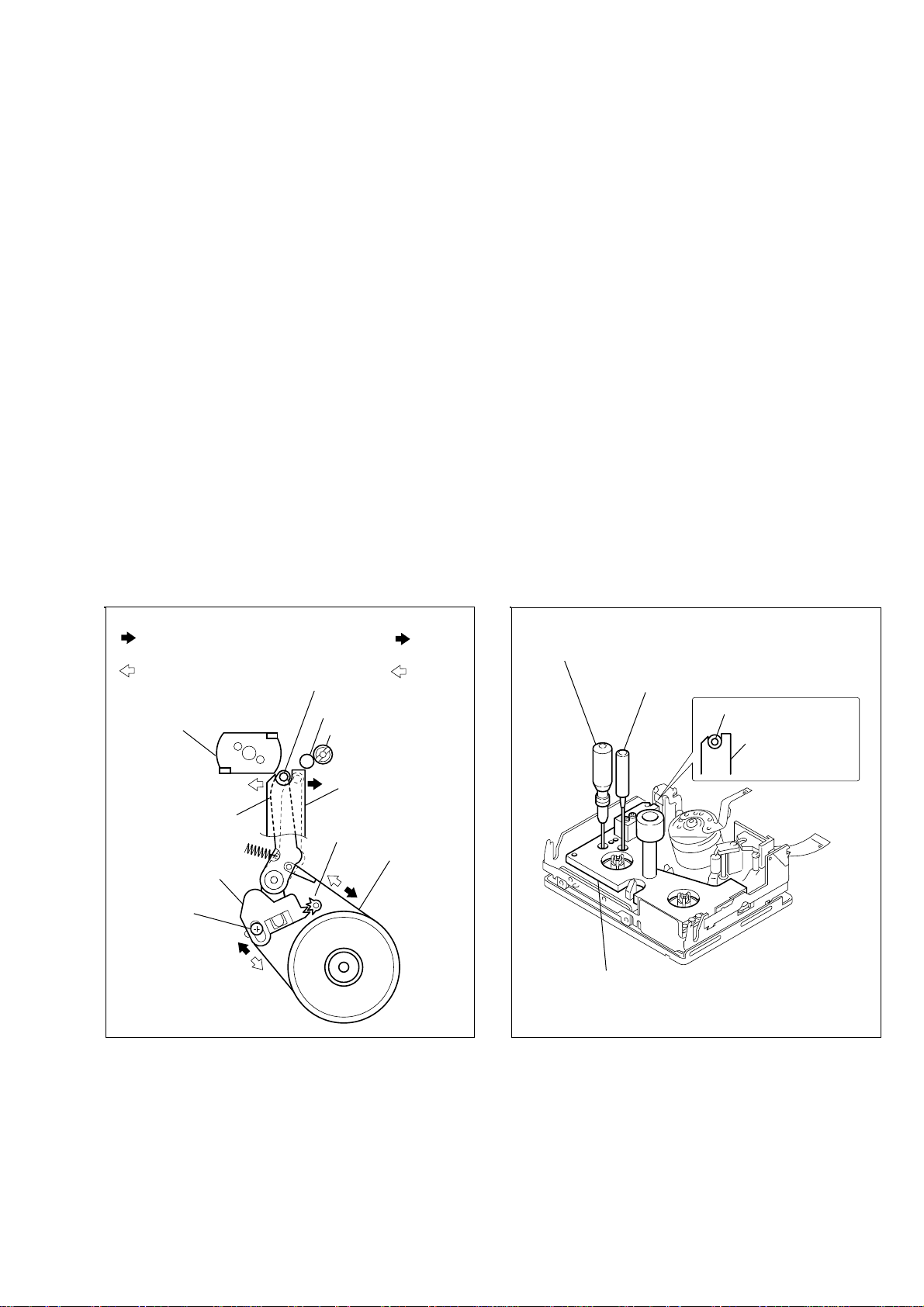
3-6. TG1 FWD Position Adjustment
l
TG1 FWD adjustment screwdriver (Ref. No. J-8)
TG1 FWD position adjustment jig (Ref. No. J-7)
Torque screwdriver (Ref. No. J-11)
TG1 guide
TG1 FWD position
adjustment jig
(Ref. No. J-7)
When the TG1 assy or S-reel table is replaced, or when a part
constituting these parts is replaced, perform the following
adjustment.
• TG1 FWD Position Adjustment
• FWD Back-tension Adjustment (Refer to section 3-7.)
• Reel table (RVS) torque check (Refer to section 3-8.)
1. Adjustment procedure
1) Establish the [RP] mode.
2) Install the TG1 adjustment jig (Ref. No. J-7) as specified by
the S/T position setting.
Note: Be careful not to damage the flexible wiring board.
3) Attach the torque screwdriver (Ref. No. J-11) and the TG1 FWD
adjustment screwdriv er (Ref. No. J-8) to the adjustment screw
block.
4) While rotating the adjustment screwdriv er a little, press it down
lightly so that it is aligned with the gear of the (FWD)
adjustment plate.
5) Loosen the adjustment screw that is tentatively tightened by
the torque screwdriver . Perform adjustment so that TG1 comes
to the center of the gauge’s groo ve when vie wed from directly
above the TG1 adjustment jig (Ref. No. J-7). Then tighten the
adjustment screw.
Tightening torque: 0.0588 N•m (0.6 kg•cm).
6) Check again that the TG1 position remains in the correct
position, then remove the jig.
When clearance in the L motor holder block assy (loading) side is smal
•
Move the position in the direction of the arrow .
• When clearance in the TG2 guide side is small
Move the position in the direction of the arrow .
L motor holder
block assy (loading)
(FWD) adjustment plate
Adjustment screw
TG1 assy
A
Fig. 3-6
TG1 guide
TG2 guide
TG3 guide
TG1 FWD position
adjustment
jig (Ref. No. J-7)
TG1 FWD adjustment
screwdriver (Ref. No. J-8)
Tension regulator band
S-reel table
assy
Fig. 3-7
— 17 —
Page 18
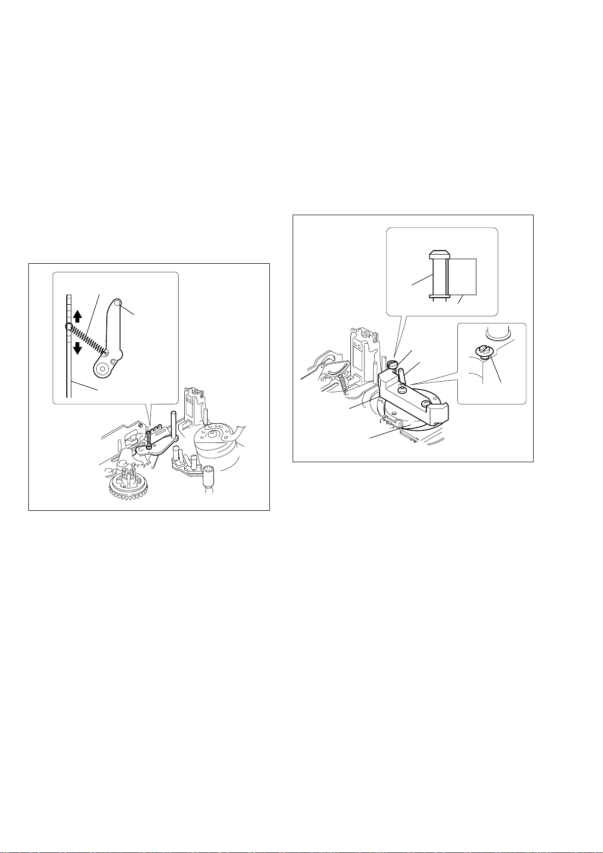
3-7. FWD Back-tension Adjustment
3-9. TG3 Guide Zenith Adjustment
1. Adjustment procedure
1) Install the Mini DV torque cassette (Ref. No. J-6).
2) Set the [RP] mode. Confirm that the torque reading of the
supply side is in the range of 0.45 to 0.55 mN•m (4.5 to 5.6
g•cm) including fluctuation. If the torque reading is outside
the specified range, perform the following adjustment.
• If the torque reading value is higher than the specification:
(Reduce the spring tension as follows.)
Shift the hook position of the tension coil spring in the direction
of A.
• If the torque reading value is lower than the specification:
(Increase the spring tension as follows.)
Shift the hook position of the tension coil spring in the direction
of B.
Tension coil spring
(tenstion regulator)
B
TG1 assy
A
LS block assy
1) Remove the drum referring to section 3-1. Install the dummy
drum (Ref. No. J-9).
2) Install the TG36 gauge (Ref. No. J-10) on top of the dummy
drum. Rotate the slant adjustment zenith screw until the TG3
guide and TG36 gauge (Ref. No. J-10) become parallel.
3) Remove all the jigs. Attach the original drum back in its original
position referring to section 3-1.
4) Clean the TG3 and TG4 guides referring to section 2-2.
5) Perform the tape path adjustment. (Refer to section 4, “Tape
Path Adjustment”.)
Roller and TG36 gauge must
be parallel.
TG3 guide
TG36 gauge
TG3 guide
TG4 guide
Slant adjustment
zenith screw
TG36 gauge
Fig. 3-8
3-8. Reel T orque Check
1. Check procedure
[FWD torque]
1) Install the Mini DV torque cassette (Ref. No. J-6).
2) Set the FWD mode. Confirm that the center of the T-reel table
torque reading value is 0.54 to 1.32 (mN•m) (5.5 to 13.5 g•cm)
and the fluctuation value is 0.39 to 0.40 (mN•m) (3.9 to 4.0
g•cm).
[RVS torque]
1) Install the Mini DV torque cassette (Ref. No. J-6).
2) Set the R VS mode (by using the EDIT SEARCH (–) button of
the machine). Confirm that the center of the S-reel table torque
reading value is 1.37 to 2.11 (mN•m) (14 to 21.5 g•cm) and the
fluctuation value is 0.39 to 0.40 (mN•m) (3.9 to 4.0 g•cm).
Dummy drum
Fig. 3-9
If either of the above specifications is not satisfied, c heck whether
the tension regulator band has any abnormality. If it has no
abnormality, replace the corresponding reel table.
— 18 —
Page 19
3-10.TG6 Guide Zenith Adjustment
w
Press the LS block assy
with force of 100 to 200 gf
(0.98 to 1.96 N)
Mechanism chassis block assy
LS cam plate
LS cam plate fixing screw
Dowel of LS arm
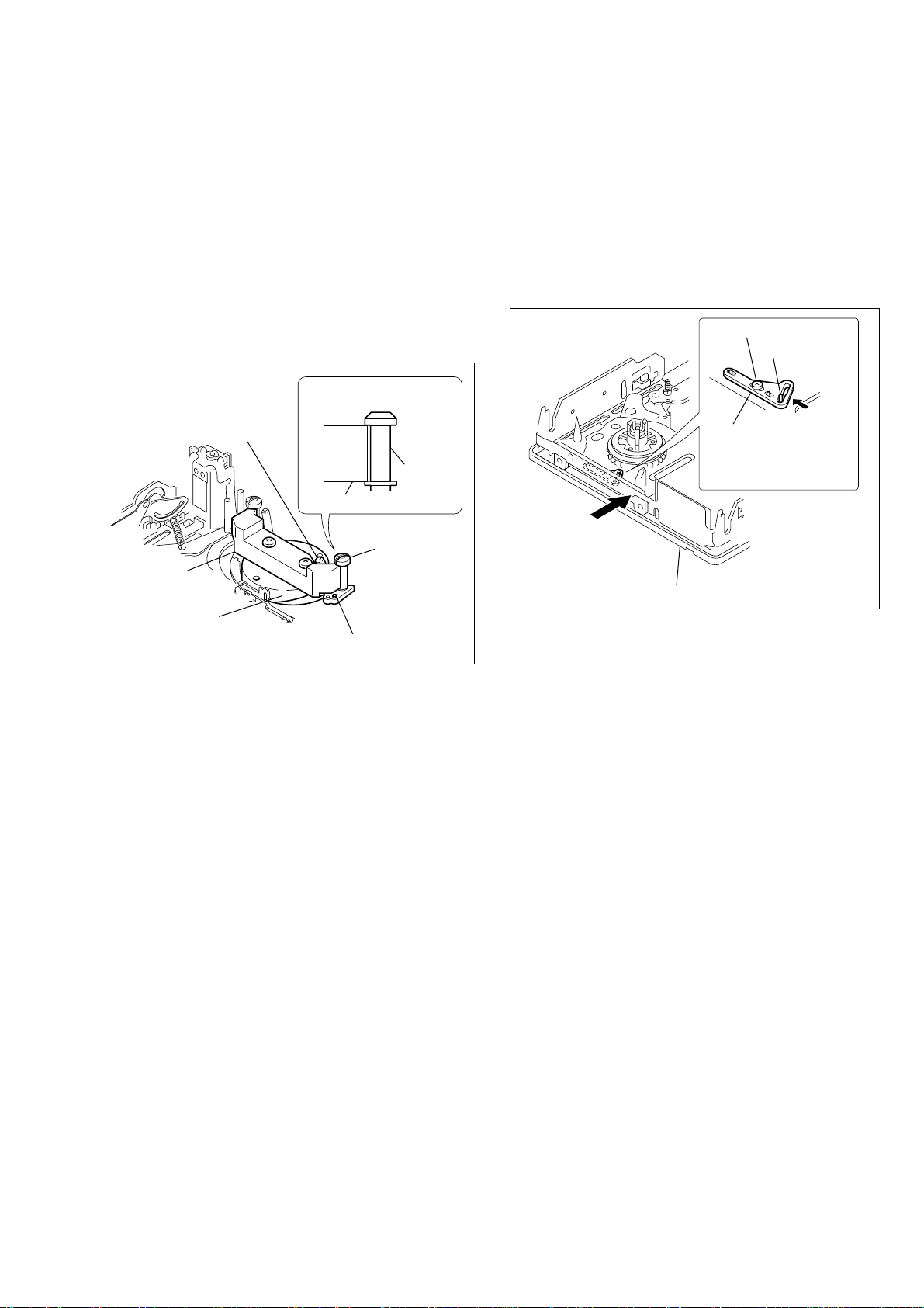
Press the LS cam plate
with force of 500 to 1000 gf
(4.9 to 9.8 N)
3-11.LS Cam Plate Position Adjustment
1. Adjustment procedure
1) Remove the drum referring to section 3-1. Install the dummy
drum (Ref. No. J-9).
2) Install the TG36 gauge (Ref. No. J-10) on top of the dummy
drum. Adjust the slant of the TG6 guide.
3) Rotate the slant adjustment zenith screw until the TG6 guide
and TG36 gauge (Ref. No. J-10) become parallel.
4) Remove all the jigs. Attach the orig inal drum back in its original
position referring to section 3-1.
5) Clean the TG5 and TG6 guides referring to section 2-2.
6) Perform tape path adjustment. (Refer to section 4, “T ape Pa th
Adjustment”.)
TG6 guide and TG36 gauge
must be parallel.
TG5 guide
TG6 guide
TG36 gauge
TG6 guide
TG36 gauge
1. Adjustment procedure
1) Loosen the LS cam fixing screw (M1.4 × 4) 1 by 180 degrees.
2) Establish the [STOP] mode.
3) While pressing down the center of the LS chassis block assy
with force of 100 to 200 gf (0.98 to 1.96 N), move the LS cam
plate toward the S-reel side and tighten the LS cam plate fixing
screw (M1.4 × 4) 1 with force of 500 to 1000 gf (4.9 to 9.8
N).
Tightening torque: 0.059 to 0.01 N•m (0.6 kg•cm).
Dummy drum
Slant adjustment zenith scre
Fig. 3-11
Fig. 3-10
— 19 —
Page 20
3-12.LS Chassis Block Assy, LS Guide Retainer
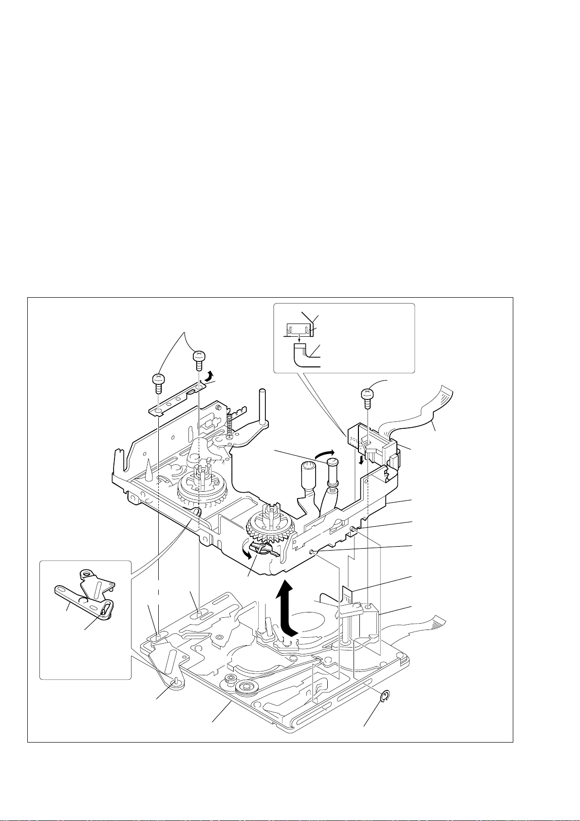
d
1. Removal procedure
1) Remove the FP-100 flexible wiring board from the FPC
connector on the FP-102 flexible wiring board.
2) Remove the screw (M1.4 × 2.5) 2. Remove the FPC holder
from DC motor (capstan).
3) Remove the two screws (M1.4 × 2) 1.
4) Remove the LS retainer in the direction of the arrow A on the
top.
5) Remove the E-type stop ring 1.5 3.
6) Remove the LS chassis block assy in the direction of the arrow
B.
1 Two screws (M1.4 × 2)
A
LS guide retainer
2. Attachment procedure
1) Confirm that the brake-T block assy has been moved in the
counter-clockwise direction C. While pressing the TG7 block
in the direction of the arrow D, insert the LS guide shafts T1
and T2 of the LS chassis block assy into the slots of the
mechanism chassis with slanted angle.
2) While inserting the LS arm dowel into the LS cam plate groove,
insert the LS guide shafts S1 and S2 into the slots of the LS
chassis block assy as shown.
3) Insert the LS guide retainer from the top, align it with the LS
guide shafts S1 and S2 and fix it with the screw (M1.4 × 2) 1.
Tightening torque: 0.059 to 0.01 N•m (0.6 kg•cm).
4) Confirm that the LS guide retainer has play, is not lifted up, is
not installed in opposite direction and has not been deformed.
5) Attach the E-type stop ring 1.5 3 into the LS guide shaft T1.
6) Insert the FPC holder into DC motor (capstan) in the direction
of the arrow E and fix it with the screw (M1.4 × 2.5) 2.
7) Connect the flexible wiring board coming from the FP-100
flexible wiring board into the FPC connector.
FP-102 flexible wiring board
FPC connector
FP-100 flexible wiring board
2 Screw (M1.4 × 2.5)
LS cam plate
Dowel of LS arm
Insert dowel of the LS
arm into the LS cam
plate groove
LS guide shaft S1
LS guide shaft
S2
Dowel of LS arm
TG7 block assy
C
Brake-T block assy
B
D
FP-102 flexible wiring board
FPC holder
E
LS chassis block assy
LS guide shaft T1
LS guide shaft T2
FP-100 flexible wiring boar
DC motor (capstan)
Mechanism chassis block assy
Fig. 3-12
— 20 —
3 E-type stop ring 1.5
Page 21
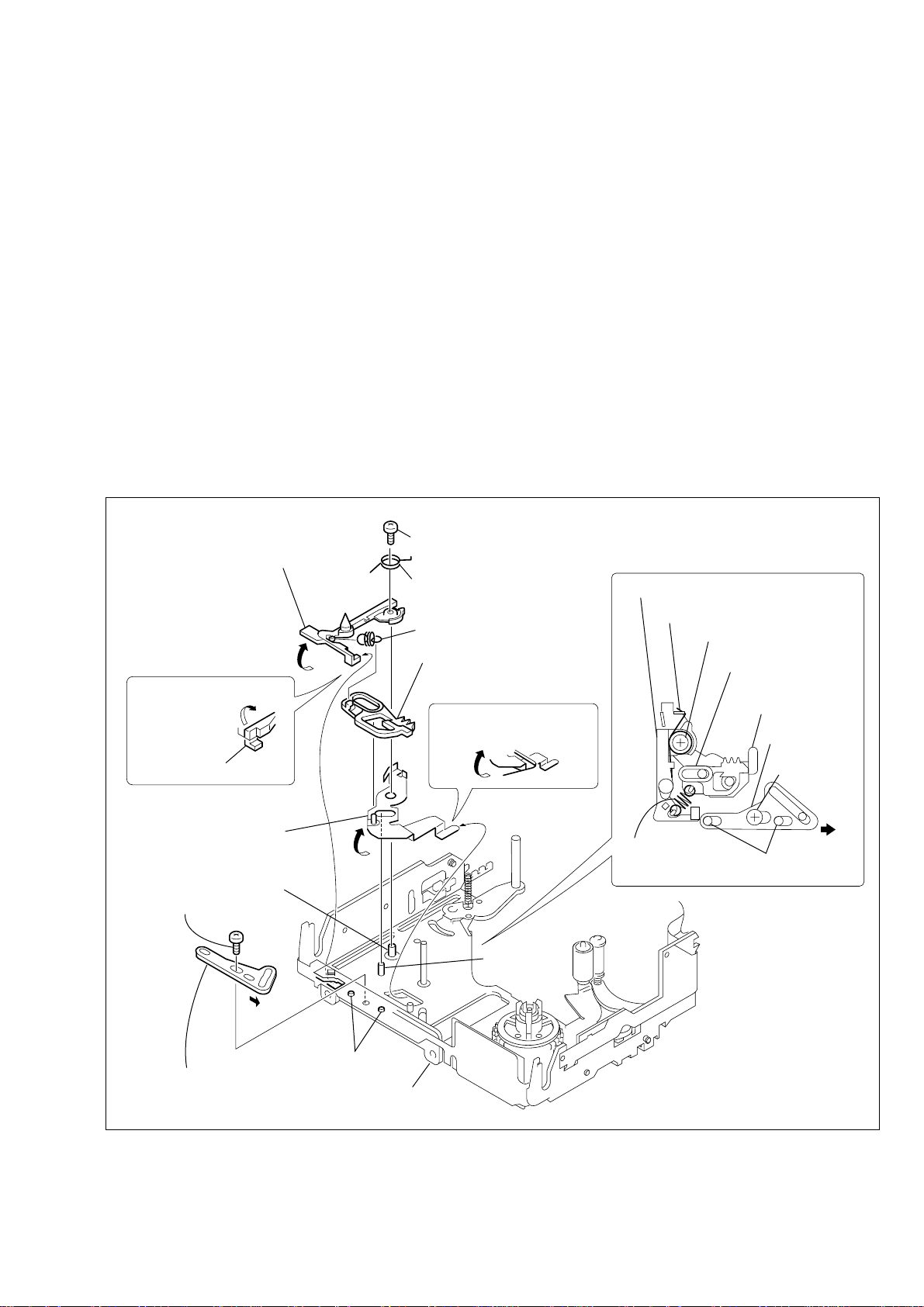
3-13.LS Cam Plate, Tension Coil Spring (Brake-S), Brake-S,
LS cam plate
Tension coil spring
(brake-S)
Tension coil spring (brake-S)
Brake-S drive arm assy
Brake-S
Torsion coil spring (brake arm)
Cassette position set-S
2 Screw (M1.4 × 2)
Screw (M1.4 × 2)
1 Screw (M1.4 × 1.4)
1 Screw
(M1.4 × 1.4)
Cassette position set-S
Cassette position set-S
Brake-S
Brake-S drive arm assy
LS cam plate
LS chassis block assy
Torsion coil spring (brake arm)
Insert the brake-S drive arm
assy under groove of the LS
chassis block assy.
Brake-S arm shaft
Brake-S pivot
shaft
Dowel
Dowel of LS chassis
block assy
Insert the cassette position
set-S under the
groove of the LS
chassis block assy.
A
B
B
C
C
Torsion Coil Spring (Brake Arm), Cassette P osition Set-S,
Brake-S Driving Arm Assy
1. Removal procedure
1) Remove the screw (M1.4 × 1.4) 1.
2) Remove the LS cam plate.
3) Remove the tension coil spring (brake-S).
4) Remove the brake-S.
5) Remove the screw (M1.4 × 2) 2.
6) Remove the torsion coil spring (brake arm).
7) Remove the cassette position set-S from groove of the LS block
assy in the direction of the arrow A.
8) Remove the brake-S drive arm assy from groove of the LS
block assy in the direction of the arrow B.
2. Attachment procedure
1) Insert the brake-S drive arm assy under groove of the LS chassis
block assy. Attach the brake-S drive arm assy to the brake-S
arm shaft and to the brake-S pivot shaft.
2) Insert the cassette position set-S under the groove of the LS
chassis block assy. Attach the cassette position set-S to the
brake-S arm shaft.
3) Attach the torsion coil spring (brake arm).
4) Attach the screw (M1.4 × 2) 2 to the brake-S arm shaft.
5) Attach the brake-S to the brake-S arm bearing and to the brakeS pivot shaft.
6) Hook the tension coil spring (brake-S) to the spring stay of the
cassette position set-S and the spring stay of the brake-S.
7) Align the slot of the LS cam plate with the dowel. Move then
in the direction toward the arrow C and attach the scre w (M1.4
× 1.4) 1.
8) Perform the LS cam plate position adjustment referring to
section 3-11.
Fig. 3-13
— 21 —
Page 22
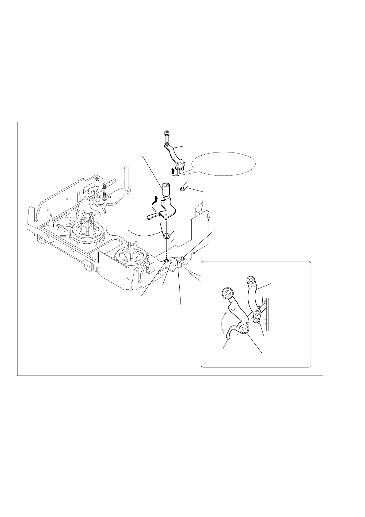
3-14.TG7 Block Assy, Torsion Coil Spring (TG7 Return, Pinch Return), Pinch Arm Assy
1. Removal procedure
1) Remove the TG7 block assy in the direction of the arrow A.
2) Remove the torsion coil spring (TG7 return) 1.
3) Remove the pinch arm assy in the direction of the arrow B.
4) Remove the torsion coil spring (pinch roller return) 2.
Pinch arm assy
B
2 T orsion coil
spring
(pinch roller return)
2. Attachment procedure
1) Install the torsion coil spring (pinch roller return) 1. (Insert
the 90-degree-bent portion of the torsion spring into the square
hole of the LS chassis block assy.)
2) Attach the pinch arm assy to the pinch arm bearing.
3) Attach the torsion coil spring (TG7 return) 1.
4) While aligning the TG7 block assy with the groove of the LS
chassis block assy, install the TG7 block assy into the TG7
block assy bearing.
TG7 block assy
Insert into groove of the
A
LS chassis block assy
1 Torsion coil spring (TG7 return)
TG7 arm bearing
Square hole
Pinch arm bearing
Groove of LS chassis
block assy
Fig. 3-14
Attachment position of
torsion coil spring
Longer one
Pinch arm assy
TG7 block assy
1 Torsion coil spring
(TG7 return)
2 Torsion coil spring
(pinch roller return)
— 22 —
Page 23
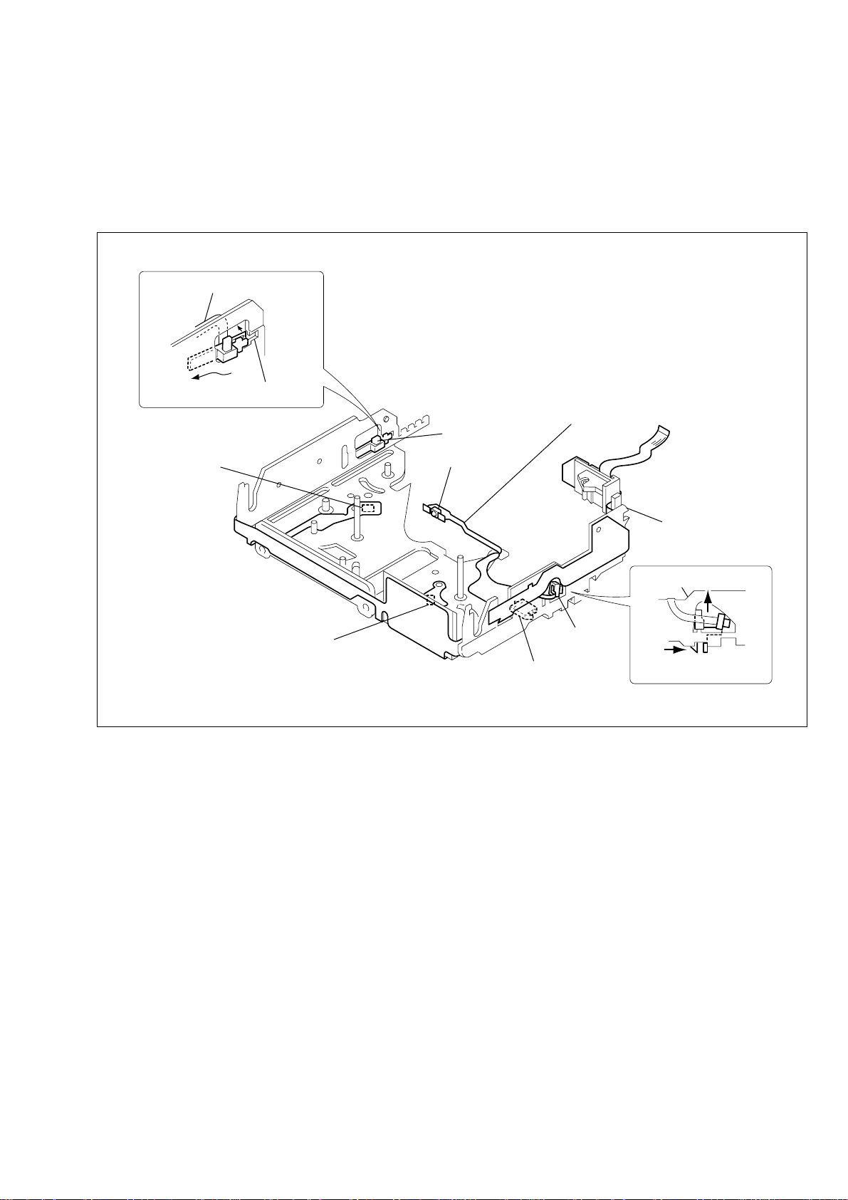
3-15.Layout Diagram of FP-102 Flexible Wiring Board
y
1. Removal procedure
1) Remove the sensor holder-T from groove of the LS chassis
block assy in the direction of the arrow A.
2) Remove the cassette holder-S by pushing out the hook under
the LS chassis block assy towards the direction of the arrow
B.
FP-102 flexible wiring board
B
LS chassis block assy
Sensor holder-S
FP-102 flexible wiring board
H901 HALL element
H902 HALL element
D901 diode
Fig. 3-15
Sensor holder-T
S903 push lever switch
LS chassis block ass
LS chassis block assy
A
Push out the hook.
— 23 —
Page 24
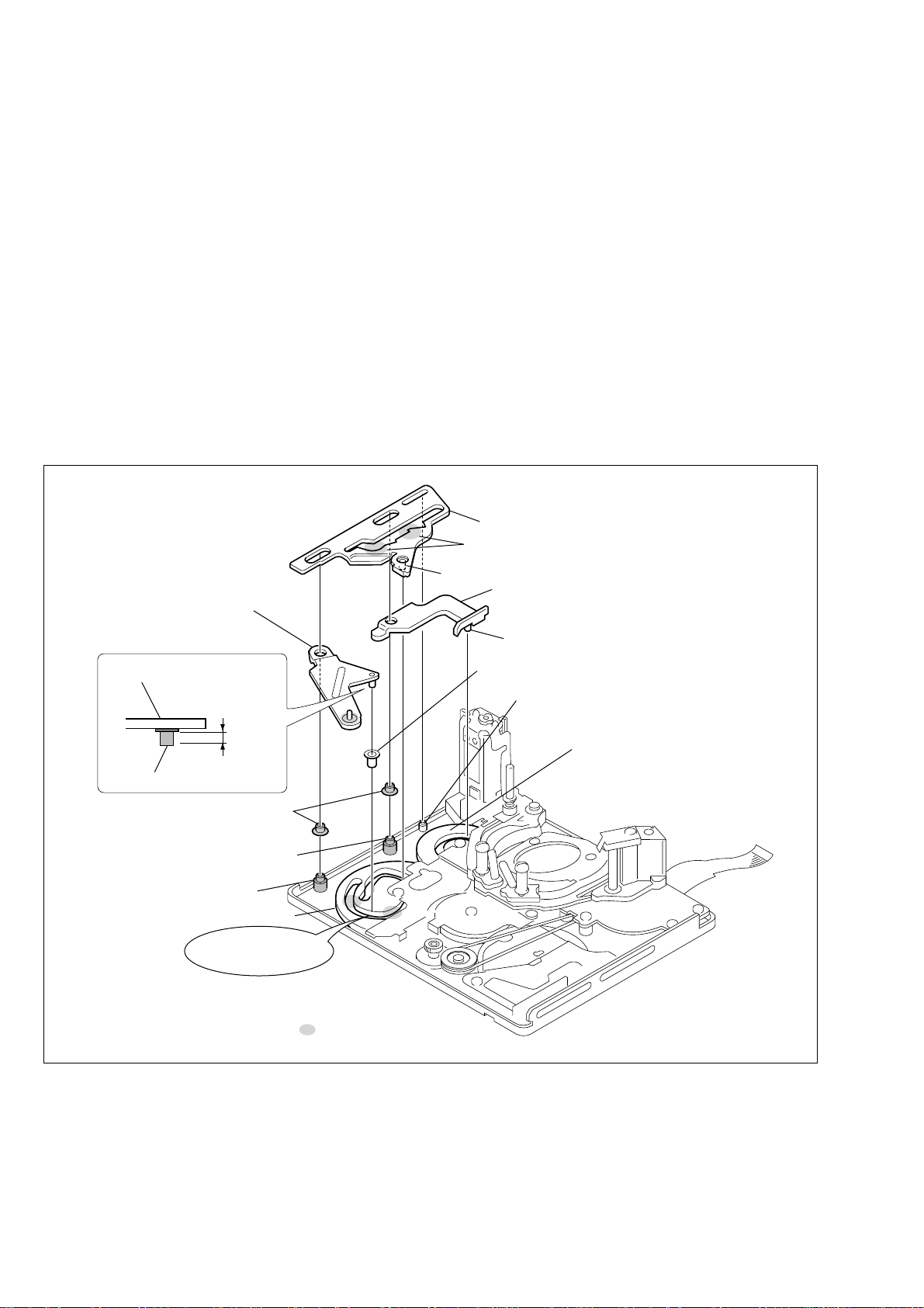
3-16.TG1 Cam Slider, LS Arm, LS Roller, Mode Gear Assy, LS Guide Roller
1. Removal procedure
1) Remove the TG1 cam slider.
2) Remove the LS arm. (At this moment, be careful that the LS
roller can come out of cam gear A groove.)
3) Remove the LS roller from the LS arm.
4) Remove the LS guide roller.
LS arm
2. Attachment procedure
1) Coat inside the LS guide roller with grease (1/4 drop of grease)
and insert it into the LS guide shafts S1 and S2.
2) Coat outside the LS guide roller with grease (1/2 drop of grease)
at the two points as shown.
3) While aligning dowel of the TG1 dri ve arm with groo ve of the
mode gear assy, insert the TG1 drive arm into the LS guide
shaft S1.
4) Coat the portion A of the LS arm with grease (1/4 drop of
grease) and insert the LS guide roller.
5) Coat both sides of the groove of the cam gear A with grease (1/
2 drop of grease). Insert the LS guide roller into groove of the
cam gear A and insert the LS arm into the LS guide shaft S2.
6) Insert the TG1 cam slider into the three positions of the LS
guide shaft S1, S2 and slider guide shaft. Insert dowel of the
TG1 cam slider into groove of the cam gear A.
7) Be careful that greasing points are correct, amount of grease is
correct and the LS arm and the TG1 drive arm are not floating.
TG1 cam slider
Overlap it with gear and coat them with grease
Dowel
TG1 drive arm
LS arm
Coat outside the LS guide
shaft S2 with grease
When attaching it, coat the hatched portion with grease.
Coat the area of
0 to 1 mm or less
from the end surface
of top of shaft
Shaft
Coat inside the LS guide
roller with grease
Coat outside the LS guide
shaft S1 with grease
Cam gear A
Insert the LS roller into
LSR J MAAa
groove of cam gear A
ίB
A
Fig. 3-16
Dowel
LS roller
Slider guide shaft
Mode gear assy
— 24 —
Page 25
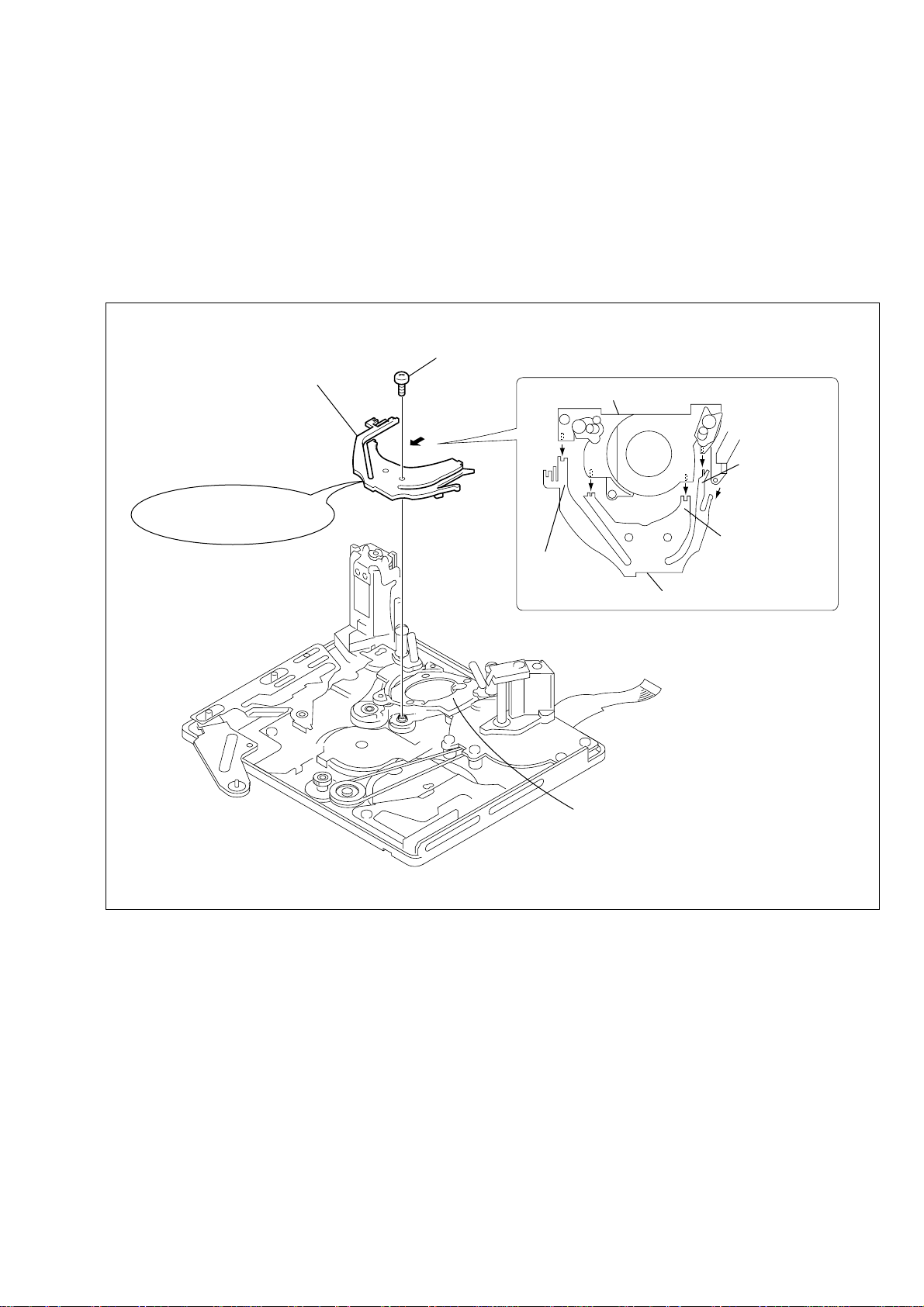
3-17.Guide Rail
1. Removal procedure
1) Remove the screw (M1.4 × 2) 1.
2) When removing the guide rail, be careful that claws of the drum
base block assy are fully released. Remove the S-side rail, Tside rail and rail of DC motor side in this order.
1 Screw (M1.4 × 2)
Guide rail
Remove it in the direction
of the arrow while being
careful not to break claw.
2. Attachment procedure
1) Engage the claws of the guide rails with the claws of the drum
base block assy starting engaging the claw from the T-side rail
and S-side rail.
Note: There must no deformation of guide rail, claws must not be
broken, claws must not override, claws must not become white,
not be stained or have no play.
2) Fix the guide rail with the screw (M1.4 × 2) 1.
Tightening torque: 0.059 ± 0.01 N•m (0.6 kg•cm)
Drum base block assy
Rail of DC motor
side (capstan)
T-side rail
S-side rail
Guide rail
Fig. 3-17
Drum base block assy
— 25 —
Page 26
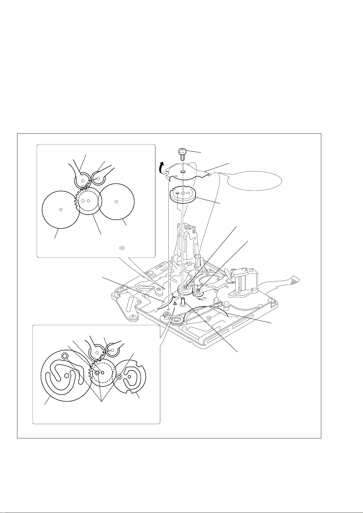
3-18.Gear Cover B, GL Driving Gear
1. Removal procedure
1) Remove the screw (M1.4 × 2) 1.
2) Remove the gear cover B in the direction of the arrow A.
3) Remove the GL drive gear.
Fig. 2
Cam gear A
When attaching it, coat the hatched portion
with grease.
Coaster-S block assy
Coaster-T block assy
Cam gear B
3 GL drive gear
2. Attachment procedure
1) Coat the cam gear A and the GL drive gear with grease (1/2
drop). (Refer to Fig. 2.)
2) Refer to Fig. 1. While adjusting phase of the GL dri ve gear as
shown, insert the GL drive gear into the GL dri ve shaft. (Insert
it while moving the GL drive gear in the clockwise direction.)
3) Insert the two claws of the gear cover B into the square holes
of mechanism chassis.
4) Fix the GL drive shaft with the scre w (M1.4 × 2) 1. Be sure
that the gear cover B must not have any play.
Tightening torque: 0.059 ± 0.01 N•m (0.6 kg•cm)
A
1 Screw (M1.4 × 2)
Gear cover B
Insert them into the
two grooves.
GL drive gear
Coaster-S block assy
Coaster-T block assy
Cam gear A
Fig. 1
GL drive shaft
Hole of the GL
drive gear
Cam gear A
In-phase markings of the
coaster-T block assy
Hole of mechanism
chassis
Phase adjustment of the GL drive gear
Hole of cam
gear B
Cam gear B
Cam gear B
GL drive shaft
Fig. 3-18
— 26 —
Page 27
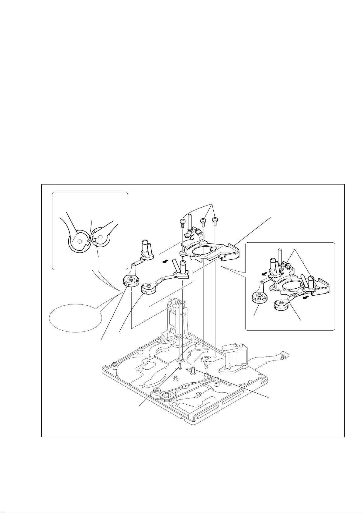
3-19.Drum Base Block Assy, Coaster-S Block Assy, Coaster-T Block Assy
Three screws (M1.4 × 2.5)
Drum base block assy
Coaster-T block assy
Groove of drum base block assy
Coaster-S block assy
GL gear shaft-T
GL gear shaft-S
Coaster-S block assy
Coaster-T block assy
In-phase marking
of coaster-T assy
Spring of coaster
S block assy
Phase adjustment of
coaster-S/T block assy
Phase must be
adjusted exactly
during installation
A
C
B
A
1. Removal procedure
1) Remove three screws (M1.4 × 2.5).
2) Move the coaster-S block assy and coaster-T block assy out
from the drum base groove in the direction of the arrow A.
3) Remove the drum base block assy.
4) Remove the coaster-S block assy from the GL gear shaft-S.
5) Remove the coaster-T block assy from the GL gear shaft-T.
2. Attachment procedure
1) Insert a coaster-S block assy and coaster-T block assy into the
drum base groove.
2) Place a drum base block assy on top of the mechanism chassis
assy. Insert a coaster-T block assy into the GL gear shaft-T.
3) Insert a coaster-S block assy in the oblique direction. While
adjusting phase so that the spring of coaster-S block assy agrees
with the GL gear lever marking of the coaster-T block assy,
insert a coaster-S block assy into the GL gear shaft-S.
Note: • There must be no phase difference.
• Do not remove coaster-S block assy and coaster-T block assy
from the drum base block assy.
4) Determine the exact position of the drum base block assy that
has been tentatively placed, on the mechanism chassis assy.
Tighten the screws at A, B and C in this order.
Tightening torque: 0.059 ± 0.01 N•m (0.6 kg•cm)
Note: Be careful that the position setting boss of drum base block assy
does not override on the mechanism chassis.
Fig. 3-19
— 27 —
Page 28
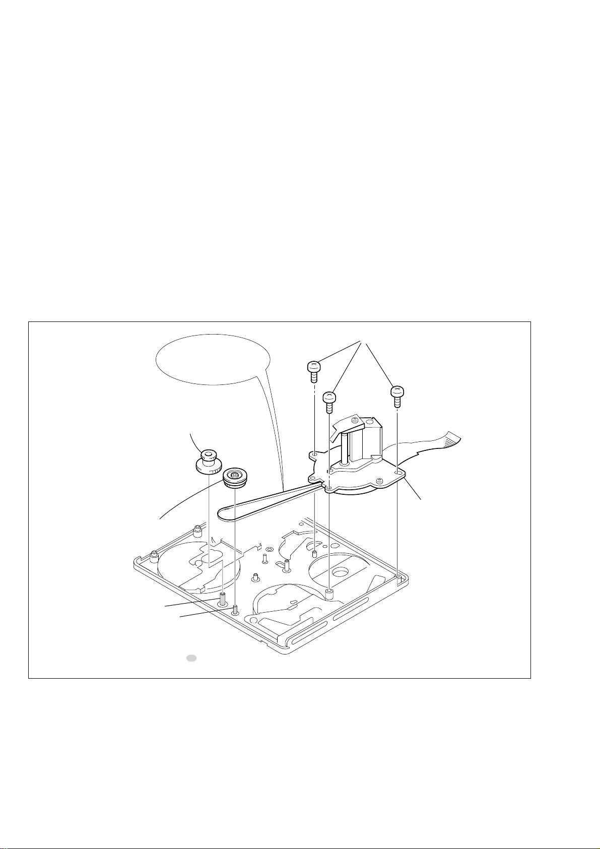
3-20.DC Motor (Capstan), Conversion Gear, Relay Gear
1. Removal procedure
1) Remove the three screws (M1.4 × 2) 1.
2) Remove DC motor (capstan). Remove belt from the pulle y of
conversion gear.
3) Remove conversion gear.
4) Remove relay gear.
Belt must be completely
free from twist or stain
when it is installed.
2. Attachment procedure
1) Coat relay gear shaft and conversion gear shaft with grease (1/
8 drop). (Amount of grease must be strictly controlled.)
2) With the larger gear of the relay gear positioned down, attach
the relay gear to the relay gear shaft.
3) With the pulley side of the conversion gear positioned up,
engage the conversion gear teeth with the relay gear teeth, and
install them.
4) Before installing the DC motor (capstan (including belt)), check
that belt is not twisted. Hook a belt on the pulley block of
conversion gear. Align three shafts with corresponding holes.
At this moment, confirm that belt does not override on the shaft.
5) Install DC motor (capstan) with three screws (M1.4 × 2) 1 in
the order of A, B and C.
A, B, C tightening torque
A tightening torque: 0.059 ± 0.01 N•m (0.6 kg•cm)
B and C tightening torque: 0.038 ± 0.01 N•m (0.4 kg•cm)
Note: Be careful that gears and belts are not damaged or dust is not attached.
Be careful also not to splash grease.
1Three screws (M1.4 × 2)
A
C
B
Relay gear
Conversion gear
Relay gear shaft
Conversion gear shaft
When attaching it, coat the hatched portion with grease.
Fig. 3-20
DC motor (capstan)
(including belt)
— 28 —
Page 29
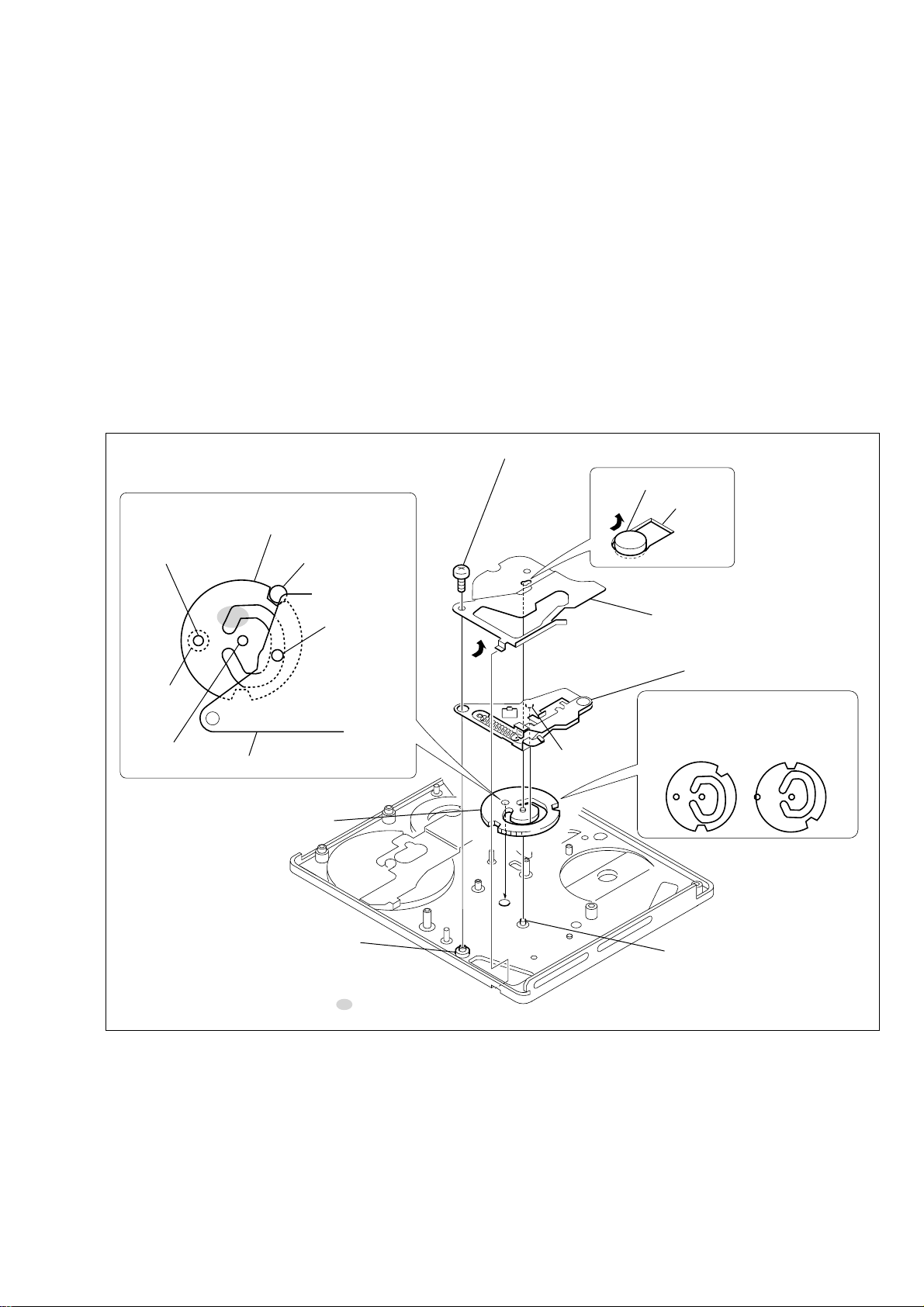
3-21.Gear Cover C, Pinch Driving Arm Assy, Cam Gear B
1. Removal procedure
1) Remove the screw (M1.4 × 2) 1.
2) Move the key slot of the gear cover C in the direction of the
arrow A and remove the gear cover C.
3) Remove the pinch drive arm assy.
4) Remove the cam gear B.
Setting the cam gear B position
Hole of the phasing
pin alignment gear
Cam gear B
Phasing pin alignment
position (hole of chassis)
2. Attachment procedure
1) Identify the front side and the rear side of a cam gear B. Align
the cam gear B shaft, the gear phasing hole and the LS chassis
hole. Then attach the cam bear B. coat groove of a cam gear
with grease (1/2 drop).
2) Align the pinch drive arm assy with the pinch driv e pivot shaft.
While aligning dowel with the cam groove of the cam gear B,
insert the pinch drive arm assy.
3) Insert the “one-step bent portion” of gear cover C into notch of
the chassis, insert the cam gear B shaft into the key hole of the
gear cover. C.
4) Insert the gear cover C into the pinch drive pivot shaft and fix
it with the screw (M1.4 × 2) 1. After tightening the screw
(M1.4 × 2) 1, move the gear cover C in or der to conf irm that
there is a little play.
Tightening torque: 0.059 ± 0.01 N•m (0.6 kg•cm)
1 Screw (M1.4 × 2)
Cam gear B shaft
Gear cover C
A
Dowel
Hole of
chassis
Cam gear B shaft
Pinch drive arm assy
Cam gear B
Pinch drive pivot shaft
When attaching it, coat the hatched portion with grease.
Fig. 3-21
Dowel
Gear cover C
Pinch drive arm assy
Identify the front side and
the rear side of a cam gear B.
Front
(correct direction)
Cam gear B shaft
Rear
(incorrect direction)
— 29 —
Page 30
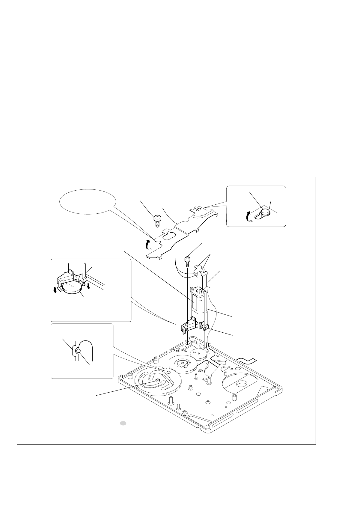
3-22.Gear Cover A, FP-100 Flexible Wiring Board
1. Removal procedure
1) Remove the screw (M1.4 × 2) 1.
2) Remove the gear cover A in the direction of the arrow A.
3) Remove the screw (M1.4 × 2.5) 2.
4) Remove soldering from the motor terminal and FP-228 flexible
wiring board (DEW sensor) that are used to connect the FP100 flexible wiring board with the motor holder block assy.
5) Remove the motor holder block assy.
Align the U-groove
with the cam gear
A shaft.
1
Screw (M1.4 × 2)
Gear cover A
2. Attachment procedure
1) Align the motor holder block assy position with the chassis
square hole and round hole. The press the motor holder block
assy with finger.
Note: Coat the worm shaft with grease (1/2 size of a rice gain).
2) Fix the motor holder block assy with the screw (M1.4 × 2.5)
2.
Tightening torque: 0.059 ± 0.01 N•m (0.6 kg•cm)
3) Install the gear cover A as follows: Hook the shaft with the k ey
slot and align the U-groove with the cam gear A shaft. Confirm
at this time that there is a play.
4) Attach the gear cover A to the cam gear A shaft and fix them
with the screw (M1.4 × 2) 1.
Tightening torque: 0.059 ± 0.01 N•m (0.6 kg•cm)
5) Connect the FP-100 flexible wiring board with the motor holder
block assy (motor terminal and FP-228 flexible wiring board
(DEW sensor)) by soldering.
Note: Do not touch the DEW sensor.
Deceleration gear A shaft
Gear cover A
FP-228 flexible wiring board
(DEW sensor)
Motor holder
block assy
Deceleration gear
Align the two points that are square
hole of chassis and round hole.
Note: Be careful not to override.
Phasing check
Gear cover A
Position where hole of the
gear is visible
Cam gear A shaft
A
Soldering
point
2
Screw (M1.4 × 2.5)
Soldering point
FP-100 flexible wiring board
Motor holder block assy
Worm shaft
When attaching it, coat the hatched portion with grease.
Fig. 3-22
— 30 —
Page 31
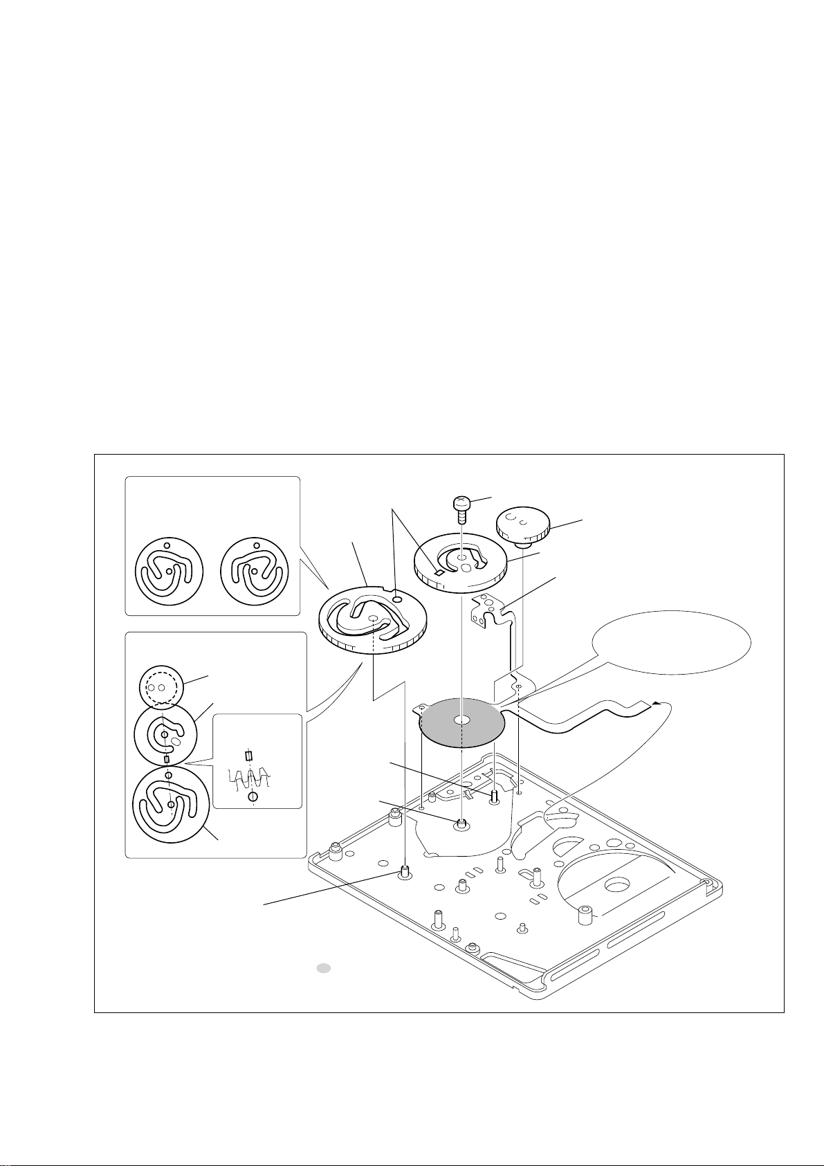
3-23.Deceleration Gear, Mode Gear Assy, FP-100 Flexible Wiring Board, Cam Gear A
1 Screw (M1.4 × 2)
Mode gear assy
Mode gear assy
Phase-matching of mode
gear assy and cam gear A
Deceleration gear
Deceleration gear
FP-100 flexible wiring board
Cam gear A
Cam gear A
Identify the front and rear
sides of cam gear A
Phase matching
position of gear
tooth
Phase matching
position of gears
When attaching it, coat the hatched portion with grease.
Coat the entire contacting
area uniformly with grease
uniformly
Cam gear A shaft
Mode gear shaft
Deceleration
gear A shaft
Front side
(correct side)
Rear side
(incorrect side)
1. Removal procedure
1) Remove the deceleration gear.
2) Remove the screw (M1.4 × 2) 1.
3) Remove the cam gear A.
4) Remove the mode gear assy.
5) Remove the FP-100 flexible wiring board.
Note 1: Do not touch the foil pattern area of the FP-100 flexible wiring
board. Any foreign materials must not be adhered.
Note 2: Do not remove the mode gear assy unnecessarily.
2. Attachment procedure
1) Install the FP-100 flexible wiring board to the mechanism
chassis. Confirm that flexible wring board is not stained,
broken, bent or damaged.
2) Coat the entire contact points of the mode pattern area of the
FP-100 flexible wiring board with the contact-point grease
(equivalent to 1.5 drops). (Any foreign materials must not be
mixed in the contact-point grease.)
3) Attach the mode gear assy to the mode gear shaft.
4) Install the deceleration gear as follows: Position the deceleration
gear with its small gear down, and engage the small gear tooth
with the mode gear tooth. Rotate the gear tooth until the phasing
marking of the mode gear assy arrives at the phasing position
of the cam gear A.
5) Identify the front and rear sides of the cam gear A. Confirm
that the marking of the cam gear A and that of the mode gear
assy agree.
6) Attach the screw (M1.4 × 2) 1 of the mode gear assy.
Tightening torque: 0.059 ± 0.01 N•m (0.6 kg•cm)
7) Connect the FP-100 flexible wiring board to the motor holder
block assy by soldering in accordance with section "3-22 [2.
Attachment procedure] step 7.
Note 1: If the FP-100 flexible wiring board is removed, replace it with a
new FP-100 board, and do not use the removed FP-100 flexible
wiring board.
Note 2: Cautions when attaching the FP-100 flexible wiring board:
1 It must not override on the mode gear shaft.
2 It must be aligned with the position setting hole.
3 It must no float, must not have stain or must not be broken.
4 Never touch the foil pattern area with hand.
Fig. 3-23
— 31 —
Page 32
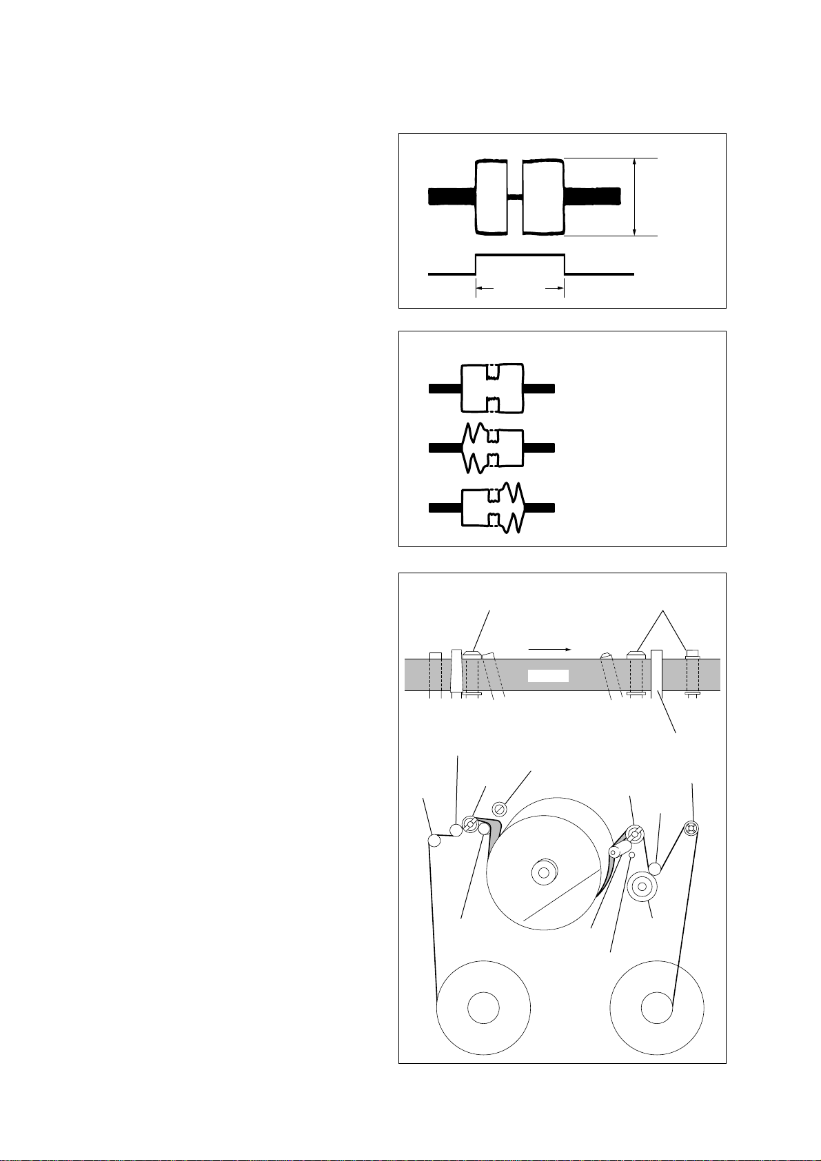
4. Tape Path Adjustment
t
e
4-1. Adjustment Preparation
1) Clean the tape running surface (tape guides, drum, capstan,
pinch roller) referring to Service Manual.
2) Connect adjustment remote commander (Ref. No. J-13) to the
LANC terminal of the machine. Set the HOLD switch to ON.
3) Connect an oscilloscope to the VC-240 board CN009 via the
CPC-8 jig (J-082-388-A). (in the case of DCR-TRV20).
Scope channel 1: VC-240 board CN009 pin w; (Note)
External trigger: VC-240 board CN009 pin qj
Note: Connect CN009 pin w; and pin ql (GND) with 75 Ω resistor
(1-247-804-11).
4) Play the tracking alignment tape (XH2-1)(Ref. No. J-5) back.
5) Select page: 3, address: 33 and data: 08. (Note)
6) Select page: 3, address: 26 and data: 31. (Note)
7) Confirm that RF waveform on scope is flat in both entrance
side and exit side. (Refer to Fig. 4-2 A).
If RF waveform is not flat in entrance side and exit side, perform
the adjustment of section 4-2. and later. (Refer to Fig. 4-2 B
and C).
8) When the required conditions of step 7) are satisfied and
adjustment/check are complete, perform [Required work upon
completion of adjustment] as described below.
[Required work upon completion of adjustment]
1) Connect adjustment remote commander (Ref. No. J-13) to the
LANC terminal of the machine. Set the HOLD switch to ON.
2) Select page: 3, address: 26 and data: 00. (Note)
3) Select page: 3, address: 33 and data: 00. (Note)
CH1
CH2
(Trigger)
Entrance side
3.3 msec
Exit side
Fig. 4-1
A
Normal
B
Entrance side is defectiv
C
Exit side is defective
Envelope
must be fla
Note: Page and address numbers differ depending on each model. Please
refer to Service Manual of respective models. Those of DCR-TR V20
are described above.
Fig. 4-2
Tape runs while keeping
contact with upper flange
TG2
TG1 TG3 TG4 TG5 TG6 TG7
TG2 guide
TG1 guide
TG3 guide
TG4 guide
FWD
Tape
TG3 and TG4 zenith
adjustment screw
Drum
TG6 guide zenith
adjustment screw
Tape runs while keeping
contact with upper flange
TG6 guide
TG5 guide
Pinch roller
Capstan
Capstan
TG7 guide
S-reel
Fig. 4-3
T-reel
— 32 —
Page 33
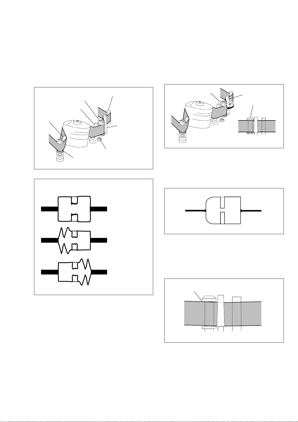
4-2. Tracking Adjustment
e
Adjustment nut (TG3)
TG2 guide
TG1
TG3
TG2
Upper flange
4-3. TG3 Guide Adjustment
1) Play the tracking alignment tape (XH2-1) (Ref. No. J-5) back.
2) Adjust TG3 guide until the envelope of entrance side w aveform
becomes flat.
3) Adjust TG6 guide until the envelope of exit side waveform
becomes flat.
Note: Do not touch or adjust TG3 and TG4 guide zenith adjustment screw .
TG3 guide
TG4 guide
TG5 guide
TG6 guide
TG1 guide
TG2 guide
TG3 and TG4 guide zenith
adjustment screw.
(Do not touch or rotate.)
Fig. 4-4
Entrance side
Exit side
1) Play the tracking alignment tape (XH2-1) (Ref. No. J-5) back.
2) Run the tape in FWD mode. Confirm that tape runs while
keeping contact with upper flange of TG3. If any clearance is
found between top flange and tape, rotate the adjustment nut
in clockwise direction until tape runs while keeping contact
with upper flange of TG3.
Fig. 4-6
When tape runs while keeping contact with upper flange of
TG3, confirm that the tracking waveform does not change. If
the tracking waveform has poor amplitude at the entrance side
as shown, perform tracking adjustment of entrance side.
Fig. 4-5
Normal
Entrance side is
defective
Exit side is defectiv
Fig. 4-7
After entrance side is adjusted, establish the R VS mode. Make
an attempt to rotate the TG3 adjustment nut by 180 degrees in
the counter-clockwise direction in order to confirm that tape
rises upward. Upon confirmation, return the TG3 adjustment
nut to the original position.
Upper flange
TG2
TG1TG3
Fig. 4-8
— 33 —
Page 34
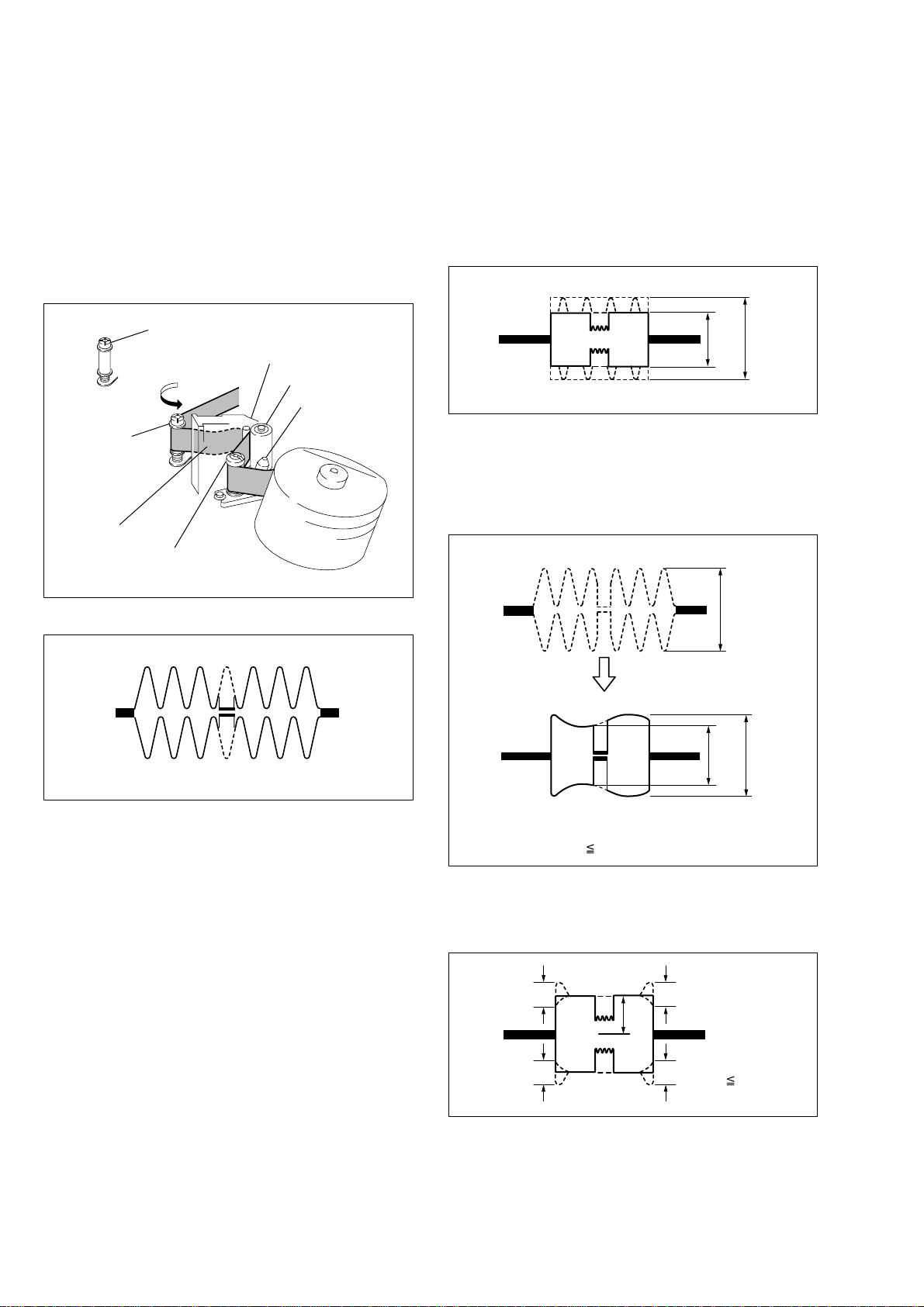
4-4. TG7 Guide Adjustment
%
x
A
1) Establish the FWD mode. Confirm that tape slack does not
occur in between capstan and TG7 guide. (Specification value:
0.5 mm or less of tape slack) If any tape slack occurs, rotate
the tG7 guide to remove the tape slack.
2) Establish the REV mode. Confirm that RF waveform at exit
side is normal. (Refer to Fig. 4-10.)
3) If the RF waveform at exit side has abnormality , rotate the TG7
nut by 90 degrees in counter-clockwise direction. Then perform
steps 1) and 2) again.
4-5. Check upon Completion of
Adjustment
1. Tracking Check
1) Play the tracking alignment tape (XH2-1) (Ref. No. J-5) back.
2) Confirm that RF waveform has amplitude of about 0.65A (65%)
in the FWD mode taking the waveform amplitude during CUE/
REV mode as A (= 100%). (Refer to Fig. 4-11.)
TG7 guide
Tape slack
TG7 nut
TG6 guide
Capstan motor
Fig. 4-9
Pinch roller
TG5 guide
0.65A
A
A: 100
Fig. 4-11
3) Confirm that difference between the minimum amplitude
(E.min) and the maximum amplitude (E.max) of RF waveform
in the FWD mode is 30% or more taking the waveform
amplitude during CUE (or REV) mode as A (= 100%).
CUE or REV mode
A=100%
FWD mode
E min E ma
Fig. 4-10
E.min: Minimum amplitude
E.max: Maximum amplitude
(E.min – E.min) 30% or (3/10 × A)
Fig. 4-12
4) Confirm that the RF waveform does not have excessive
fluctuation.
C
C
C
A
C
C 1/8 ×
Fig. 4-13
— 34 —
Page 35
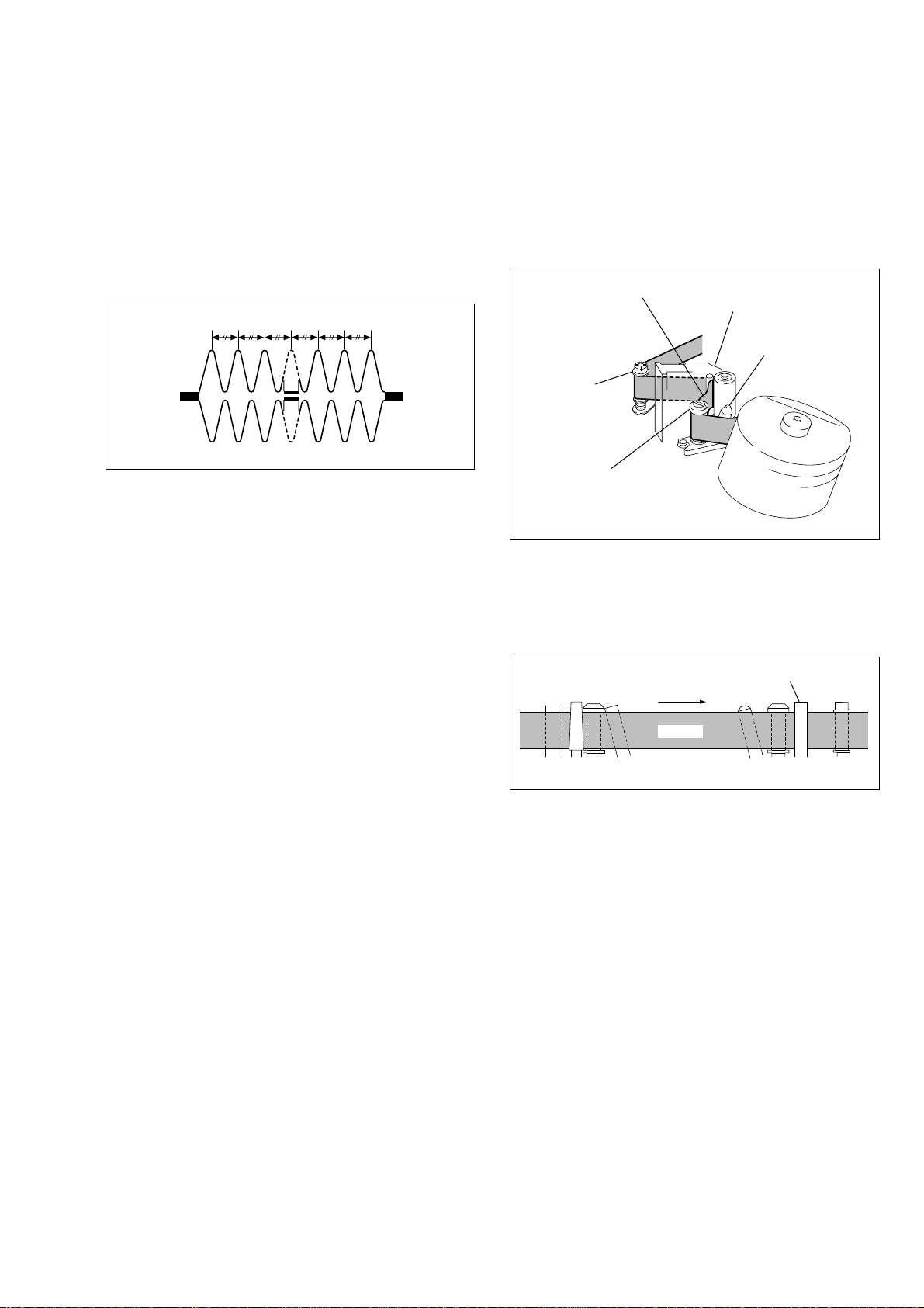
2. CUE/REV Check
Capstan motor
Tape slack
TG7 guide
TG6 guide
TG5 guide
Capstan
FWD
TG1 TG3 TG4 TG5 TG6 TG7
TG2
Tape
1) Play the tracking alignment tape (XH2-1) (Ref. No. J-5) back
and enter the REV mode. Confirm that pitches between peaks
of RF waveform are equally spaced. (Refer to Fig. 4-14.)
If pitches between peaks of RF waveform are not equal, perform
sections "4-2 Tracking Adjustment" and "4-4. TG7 Guide
Adjustment".
2) Enter the CUE mode. Confirm that pitches between peaks of
RF waveform are equally spaced. (Refer to Fig. 4-14.) If
pitches between peaks of RF waveform are not equal, perform
sections "4-2 Tracking Adjustment".
Fig. 4-14
3. Rise-up Check
1) Play the tracking alignment tape (XH2-1) (Ref. No. J-5) back.
2) Establish the FWD playback mode. Confirm that RF waveform
rises up in two seconds or less. Confirm also at this time that
tape slack does not occur at around pinch roller.
3) Run a tape in CUE/REV mode and FF/REW mode. After that
play the tape back and confirm that RF waveform rises up in
two seconds or less.
4) Repeat steps 2) and 3) repeatedly.
Fig. 4-15
4. Tape Run Check
Run a tape in CUE/REV mode. Confirm to see that major tape curl
does not occur at TG2 lower taper, TG3 upper flange, TG6 upper
flange and TG7 upper flange during CUE/REV mode.
Fig. 4-16
— 35 —
Page 36
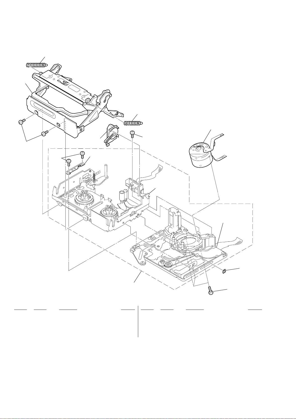
5. Exploded View
5-1. Cassette Compartment Block Assy, Drum Assy Block
703
Note: Type name and part code number of the M901 drum
702
differ depending on models. Refer to Service Manual
of the respective models.
704
M901
(Note)
701
701
705
709
706
LS chassis block
assembly
(See page 37)
Mechanism chassis block
assembly
(See page 38)
707
708
Ref. No. Part No. Description Remarks Ref. No. Part No. Description Remarks
701 3-703-816-14 SCREW (M1.4)
702 X-3950-369-2 CASSETTE COMPARTMENT ASSY
703 3-059-082-01 SPRING, TENSION
704 3-059-208-01 SPRING (CASSETTE COMPARTMENT T)
705 X-3950-370-2 DAMPER ASSY
706 3-059-101-01 RETAINER, LS GUIDE
707 7-624-102-04 STOP RING 1.5, TYPE -E
708 A-7028-133-A MD(J100) SUB ASSY (Y)
709 3-703-816-41 SCREW (M1.4X2.5), SPECIAL HEAD
M901 — Note — DRUM
701
— 36 —
Page 37
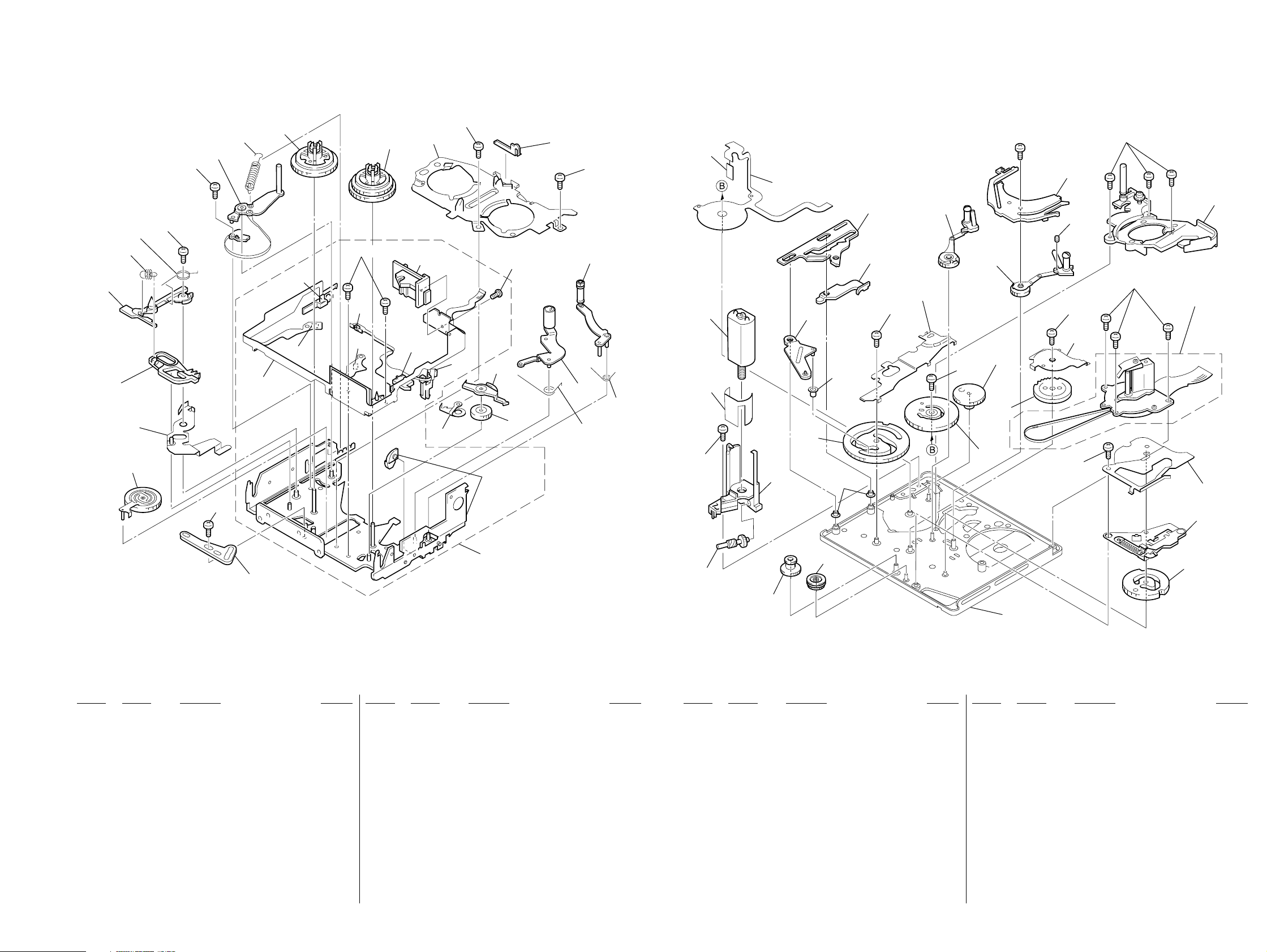
5-2. LS Chassis Block Assy
)
5-3. Mechanism Chassis Block Assy
757 @
756 @
755 @
758 @
754 @
753 @
759 @
760 @
762 @
761 @
752 @
763 @
FP-102
(Note)
Q901
H901
764 @
not supplied @@@
D901
H902
765 @
not supplied @@@
S903
774
752 @
Q902
772
not supplied @@@
766
not supplied @@@
768
770
773
771
752 @
769
811
M903
808
807
812
804
810
806
809
805
813
814
815
816
820
815
821
817
819
818
815
822
815
825
815
807
824
823
815
M902 (Including belt
826
827
775
751 @
Note: FP-102 is included in the LS sub assy and is attached
to chassis by hot-press.
Because installation of FP-102 requires a very high
accuracy, FP-102 is not supplied as an independent
service parts.
Ref. No. Part No. Description Remarks Ref. No. Part No. Description Remarks
751 3-059-173-01 PLATE, LS CAM
752 3-059-100-01 SCREW (M1.4X1.4), SPECIAL HEAD
753 X-3950-364-1 GEAR ASSY, GOOSENECK
754 X-3950-371-1 ARM ASSY, BRAKE (S) DRIVING
755 3-059-166-01 BRAKE (S)
756 3-059-146-01 POSITIONING (S), CASSETTE
757 3-059-167-01 SPRING (BRAKE S), TENSION COIL
758 3-059-169-01 SPRING (BRAKE S ARM), TORSION
759 3-703-816-14 SCREW (M1.4)
760 3-059-090-01 SCREW (M1.4X2.5), SPECIAL HEAD
761 X-3950-358-2 TG1 ASSY
762 3-059-156-01 SPRING (TENSION REGULATOR)
763 X-3950-365-2 TABLE ASSY, S REEL
764 X-3950-366-1 TABLE ASSY, T REEL
765 X-3950-361-1 PLATE ASSY, RETAINER
766 3-059-093-01 RETAINER, LED
768 A-7094-819-A TG7 BLOCK ASSY
769 3-059-165-01 SPRING (TG7 RETURN), TORSION
770 X-3950-359-1 ARM ASSY, PINCH
771 3-059-161-01 SPRING (PINCH RETURN), TORSION
772 3-059-170-01 BRAKE (T)
773 3-059-171-01 GEAR (T), BRAKE
774 3-059-172-01 SPRING (T), BRAKE
775 A-7094-816-A LS BLOCK ASSY
D901 8-719-078-71 DIODE LA57A,SO (TAPE LED)
H901 8-719-067-74 ELEMENT, HOLE HW-105A-CDE-T (S REEL)
H902 8-719-067-74 ELEMENT, HOLE HW-105A-CDE-T (T REEL)
Q901 8-729-028-71 TRANSISTOR PN 166, SO (TAPE END)
Q902 8-729-028-71 TRANSISTOR PN 166, SO (TAPE TOP)
S903 1-771-326-41 SWITCH, PUSH LEVER (1 KEY) (CC DOWN)
801
803
828
802
not supplied @@@
Ref. No. Part No. Description Remarks Ref. No. Part No. Description Remarks
801 3-059-211-01 GEAR, CONVERSION
802 3-059-220-01 GEAR, RELAY
803 3-059-187-01 SHAFT, WORM
804 3-059-186-03 HOLDER, MOTOR
805 3-060-002-01 ROLLER, LS GUIDE
806 3-059-189-01 GEAR (A), CAM
807 3-703-816-41 SCREW (M1.4X2.5), SPECIAL HEAD
808 3-059-225-01 SHIELD, MOTOR
809 3-059-191-01 ROLLER, LS
810 3-059-190-01 ARM, LS
811 1-677-049-11 PWB, FP-228 FLEXIBLE
812 1-677-084-11 PWB, FP-100 FLEXIBLE
813 3-059-149-01 SLIDER, TG1 CAM
814 3-059-148-01 ARM, TG1 DRIVING
815 3-703-816-14 SCREW (M1.4)
816 3-059-117-01 COVER (A), GEAR
817 X-3950-367-1 GEAR ASSY, MODE
818 3-059-139-01 GEAR, GL DRIVING
819 3-059-188-01 GEAR, DECELERATION
820 A-7094-818-A COASTER (S) BLOCK ASSY
821 A-7094-817-A COASTER (T) BLOCK ASSY
822 3-059-126-01 RAIL, GUIDE
823 3-962-914-01 SCREW (M1.4X2)
824 A-7094-822-A DRUM BASE BLOCK ASSY
825 3-059-118-01 COVER (B), GEAR
826 3-059-083-01 COVER (C), GEAR
827 X-3950-368-1 ARM ASSY, PINCH DRIVING
828 3-059-192-01 GEAR (B), CAM
M902 8-835-685-01 MOTOR, DC SCD18A/C-NP (INCLUDING BELT)
M903 A-7094-823-A MOTOR BLOCK ASSY, L
— 37 — — 38 —
Page 38
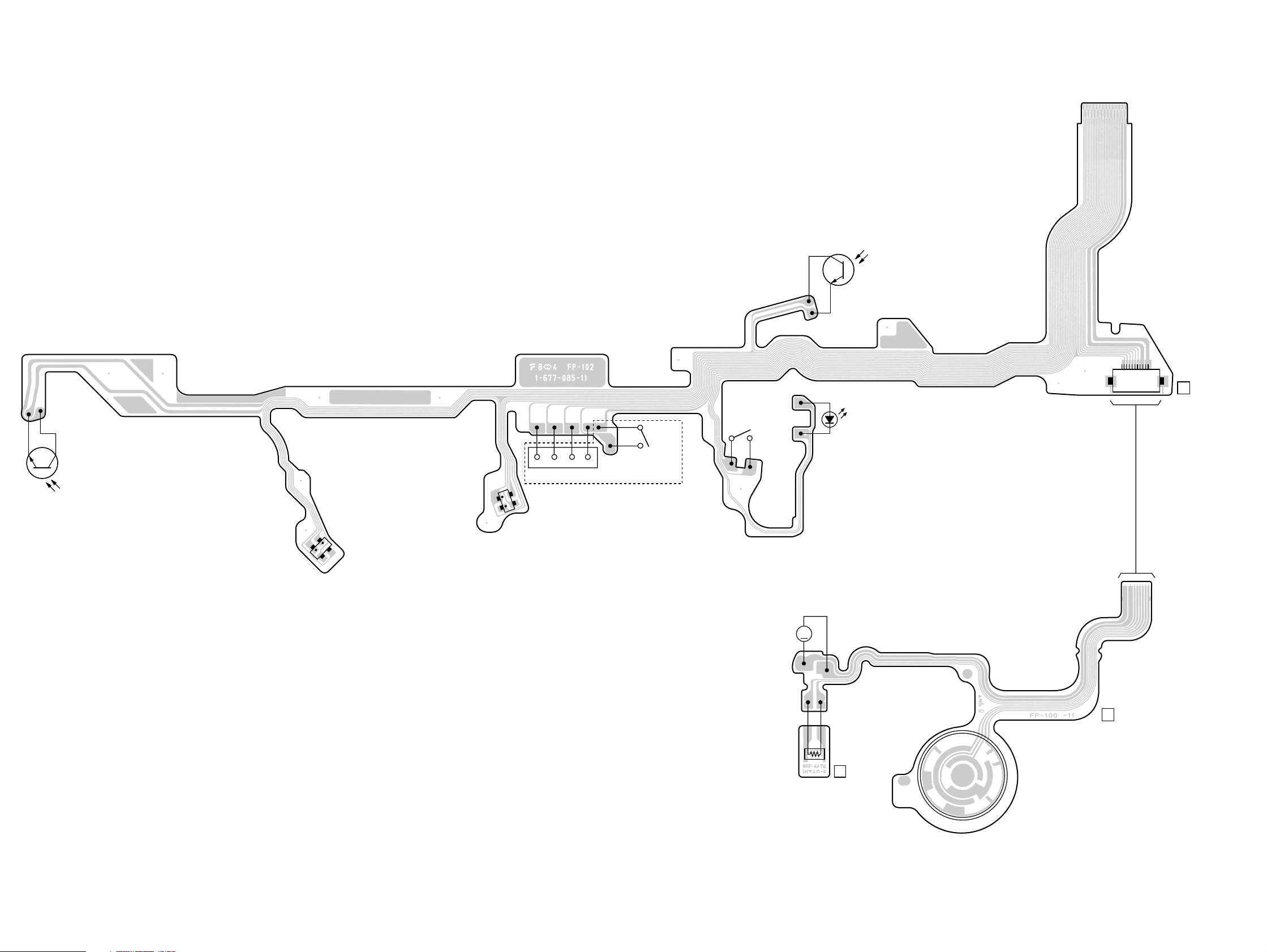
6. Printed Wiring Boards and Schematic Diagrams
FP-102 FLEXIBLE BOARD
127
Q902
TAPE TOP
SENSOR
Q901
TAPE END
SENSOR
H901
S REEL
SENSOR
H902
T REEL
SENSOR
CN901
S901
(REC PROOF)
S903
(CC DOWN)
M903
LOADING
MOTOR
10
1-677-085-
D901
(TAPE LED)
1
11
101
FP-100 FLEXIBLE BOARD
M
DEW
SENSOR
11
1-677-049-
FP-228
FLEXIBLE BOARD
— 39 — — 40 —
11
1-677-084-
S902
MODE SWITCH
Page 39
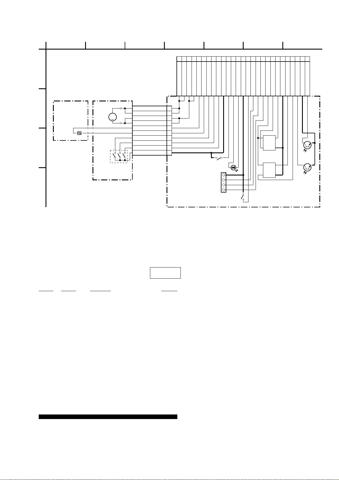
1
4
73265
123456789
DEW-
A
B
C
FP-228
FLEXIBLE
DEW
SENSOR
M903
LOADING
MOTOR
S902
MODE
SWITCH
M
LM_LOAD
1LM_LOAD
2LM_LOAD
3LM_UNLOAD
4LM_UNLOAD
5DEW+
6DEW-
7MODE A
8MODE B
9MODE C
10SW_COM
LM_LOAD
LM_UNLOAD
DEW+
LM_UNLOAD
S903
(CC DOWN)
FP-100
FLEXIBLE
D
FP-102
FLEXIBLE
16
1011121314151617181920212223242526
CHIME_SCK
CHIME_SDA
XMODE_SW_A
XMODE_SW_B
D901
(TAPE LED)
CN901
4P
XMODE_SW_C
SW_COM/SW_GND
S901
(REC PROOF)
TAPE_LED_A
TAPE_LED_K
XCCDOWN_SW
MIC/REC_SW_GND
XREC_PROOF
CHIME_VDD
Vcc -
+G
H902
T REEL
SENSOR
H901
S REEL
SENSOR
TREEL+
HALL_VCC
-Vcc
G+
TREEL-
SREEL-
HALL_GND
SREEL+
TAPE_END
TOP/END_GND
Q902
TAPE TOP
SENSOR
Q901
TAPE END
SENSOR
27
27P
TAPE_TOP
7. Electrical Parts List FP-102
Ref. No. Part No. Description Remarks
FP-102 FLEXIBLE (Not supplied)
**************************
< DIODE >
D901 8-719-078-71 DIODE LN57A.SO
< HOLE ELEMENT >
H901 8-719-067-74 DIODE HW-105A-CDE-T
H902 8-719-067-74 DIODE HW-105A-CDE-T
< TRANSISTOR >
Q901 8-729-028-71 TRANSISTOR PN166.SO
Q902 8-729-028-71 TRANSISTOR PN166.SO
< SWITCH >
S903 1-771-326-41 SWITCH, PUSH (1KEY) (CC DOWN)
***********************************************************
(Ref.No.;6000Series)
— 41 —
Page 40

DV MECHANICAL ADJUSTMENT MANUAL VI
9-929-807-11
Sony Corporation
Personal VIDEO Products Company
— 42 —
Printed in Japan © 2000.3
2000C1671-1
Published by Safety & Service Engineering Dept.
 Loading...