

Sony JumboTron Operating Instructions Manual
J umboTr on
Unit Alignment
Contr oller
3-864-807-13 (1)
Operating Instructions
Before operating the unit, please read this manual
thoroughly and retain it for future reference.
JME-UA200
1998 by Sony Corporation
1

Owner’s Record
The model and serial numbers are located on the rear.
Record the serial number in the space provided below.
Refer to these numbers whenever you call upon your Sony
dealer regarding this product.
Model No. JME-UA200 Serial No.
WARNING
To prevent fire or shock hazard, do not
expose the unit to rain or moisture.
To avoid electrical shock, do not open the
cabinet. Refer servicing to qualified
personnel only.
For the customers in the U.S.A.
This equipment has been tested and found to comply with
the limits for a Class A digital device, pursuant to Part 15 of
the FCC Rules. These limits are designed to provide
reasonable protection against harmful interference when the
equipment is operated in a commercial environment. This
equipment generates, uses, and can radiate radio frequency
energy and, if not installed and used in accordance with the
instruction manual, may cause harmful interference to radio
communications. Operation of this equipment in a residential
area is likely to cause harmful interference in which case the
user will be required to correct the interference at his own
expense.
You are cautioned that any changes or modifications not
expressly approved in this manual could void your authority
to operate this equipment.
For the customers in Europe
This product with the CE marking complies with both the
EMC Directive (89/336/EEC) and the Low Voltage Directive
(73/23/EEC) issued by the Commission of the European
Community.
Compliance with these directives implies conformity to the
following European standards:
• EN60950: Product Safety
• EN55103-1: Electromagnetic Interference (Emission)
• EN55103-2: Electromagnetic Susceptibility (Immunity)
This product is intended for use in the following
Electromagnetic Environment(s):
E1 (residential), E2 (commercial and light industrial), E3
(urban outdoors) and E4 (controlled EMC environment, ex.
TV studio).
2

Table of Contents
Overview
About This Manual............................................................. 4
Precautions ........................................................................ 4
Overview of the JumboTron System................................ 5
Images to be displayed on the JumboTron screen ..................5
Structure of the JumboTron screen .........................................6
Configuration of the JumboTron system.................................8
Features.............................................................................. 9
Locations and Functions of Parts and Controls
Locations and Functions of Parts and Controls........... 10
Front panel ............................................................................10
Rear panel ............................................................................. 11
Connections
Connections..................................................................... 12
Connecting a JumboTron display unit ..................................12
Connecting several JumboTron display units .......................12
Adjustments and Checkings
Displaying a Test Signal on a JumboTron Display Unit 13
Adjusting the Luminance Manually ............................... 18
Displaying the Luminance Level before Adjustment/
Displaying the Factory Preset Data/Storing the Currently
Displayed Data.................................................................26
Adjusting the Luminance Automatically Using a Unit
Alignment Sensor (JTU-35, LDU-15 and LDU-30
Only)............................................................................... 29
When Using the Unit Alignment Sensor JME-US35C,
JME-US1515 or JME-US1540 ........................................30
When Using the Unit Alignment Sensor JME-US30L .........36
Checking the JumboTron Display Unit Functions........ 44
Selecting the check mode......................................................44
Resetting the microprocessor in a JumboTron display unit to
its initial condition (UNIT Reset) ....................................46
Checking the operation of the indicator on the rear of a
JumboTron display unit (LED Check).............................46
Checking the blinking or lighting operation of a JumboTron
display unit (Cursor Check Menu)...................................48
Checking the operation of the test signal generator in a
JumboTron display unit (UNIT SPG)..............................49
Checking the communication between the controller and a
JumboTron display unit (Ask UNIT Type)......................50
Checking the revised light emission data of each dot, HV
current value of a unit or a defective cell (Revise Data
Menu)...............................................................................51
Checking the present conditions of the JumboTron display
unit (Unit Condition) (LDU-15, LDU-30 only)...............55
Changing the fan speed of a JumboTron display unit (Fan
Speed) (LDU-15 only) ..................................................... 56
Others
Specifications ....................................................back cover
3

About This Manual
Precautions
On safety
This instruction manual is mainly aimed at the maintenance/service
personnel.
It explains how to use the JME-UA200 unit alignment controller, which is
used to adjust and inspect the JumboTron display units of the JumboTron
system.
•Do not forcibly bend the power cord. Do not place or drop any heavy
object on it. If the power cord has been damaged, a fire or electric shock
hazard may occur.
•To disconnect the power cord, pull it out by the plug. Never pull the cord
itself.
•Do not use a damaged power cord.
•Do not drop any liquid or solid object into the cabinet.
On cleaning
•Clean the case and front panel with a dry soft cloth, or a soft cloth
slightly moistened with a mild detergent solution. Do not use any organic
solvents, such as alcohol or benzine which might damage the finish.
•Be sure to unplug the unit before cleaning.
4
Overview of the JumboTron System
The JumboTron system displays video images on a large screen
(JumboTron screen) located either outdoors or indoors. Images from video
sources such as a VCR, video camera and computer can be displayed on
the screen.
The JumboTron system provides superb bright images with high
resolution, regardless of whether it is day or night, indoors or outdoors.
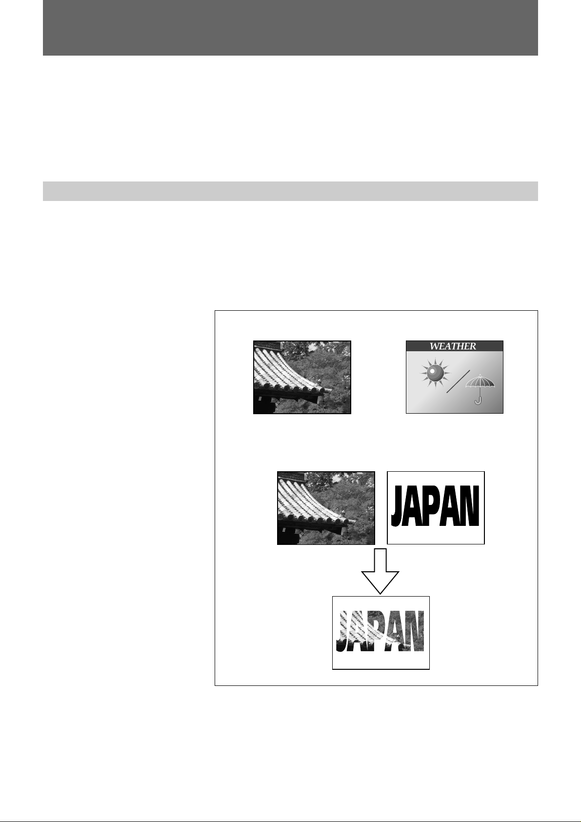
Images to be displayed on the JumboTron screen
The JumboTron system can display the following three types of images:
[a] Video images input from equipment such as a VCR, video camera
and video disc (INPUT 1)
[b] Computer graphics (INPUT 2)
[c] Mixed images of INPUT 1 and INPUT 2
(INPUT 1 images are superimposed on the monochrome area of
INPUT 2 images.)
[a] INPUT 1 [b] INPUT 2
[c] Mixed images
INPUT 1
Mixed images
INPUT 2
5
Overview of the JumboTron System
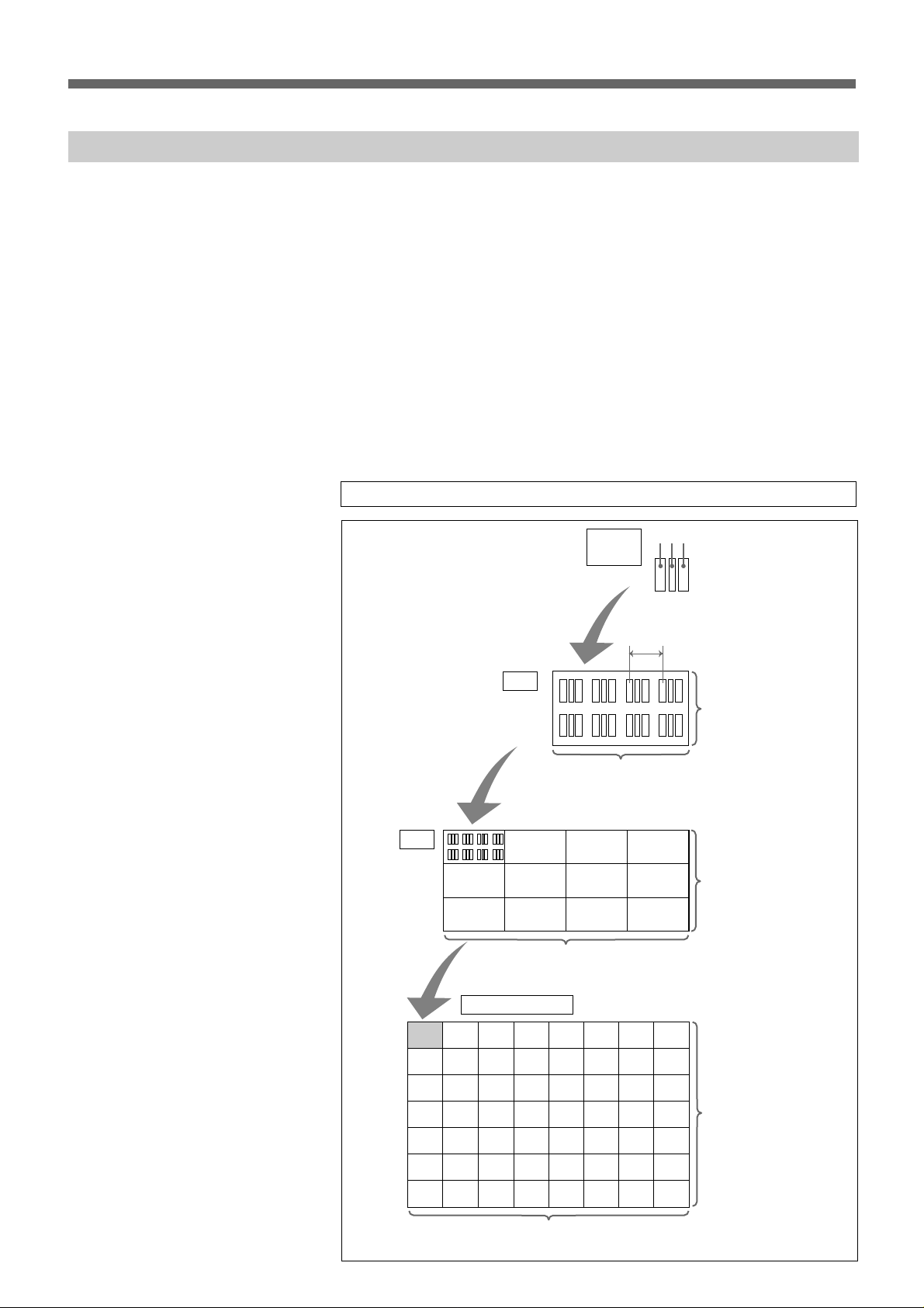
Structure of the JumboTron screen
Two types of the JumboTron screen are available. One is the conventional
CRT type screen in which light emitting bodies of three primary colors (R,
G and B), “Trinilite,” are used as the light emitting element. The other is
the new LED type screen in which light emitting diodes of the three
primary colors are used.
The basic element of the JumboTron screen is an RGB trio (dot).
A “cell” consists of the dots arranged at a certain interval (picture element
pitch) and a “unit (JumboTron display unit)” consists of 12 cells for the
CRT type and 16 cells for the LED type.
There are four unit types, the JTU-35 series (with 35-mm picture element
pitch) and JTU-17 series (with 17.5-mm pitch) of the CRT type, and the
LDU-15 series (with 15-mm pitch) and LDU-30 series (with 30-mm pitch)
of the LED type. You can configure a large JumboTron screen by
arranging the JumboTron display units vertically and horizontally to suit
various uses or locations.
CRT type
JTU-35 series
Unit
Cell
4 cells (16 dots)
RGB trio
(dot)
4 dots
B R G
Picture element pitch
2 dots
3 cells
(6 dots)
JumboTron screen
NTSC:
max. 80 units
(240 cells =
480 dots)
PAL:
max. 96 units
(288 cells =
576 dots)
NTSC: max. 40 units (160 cells = 640 dots)
PAL: max. 48 units (192 cells = 768 dots)
6
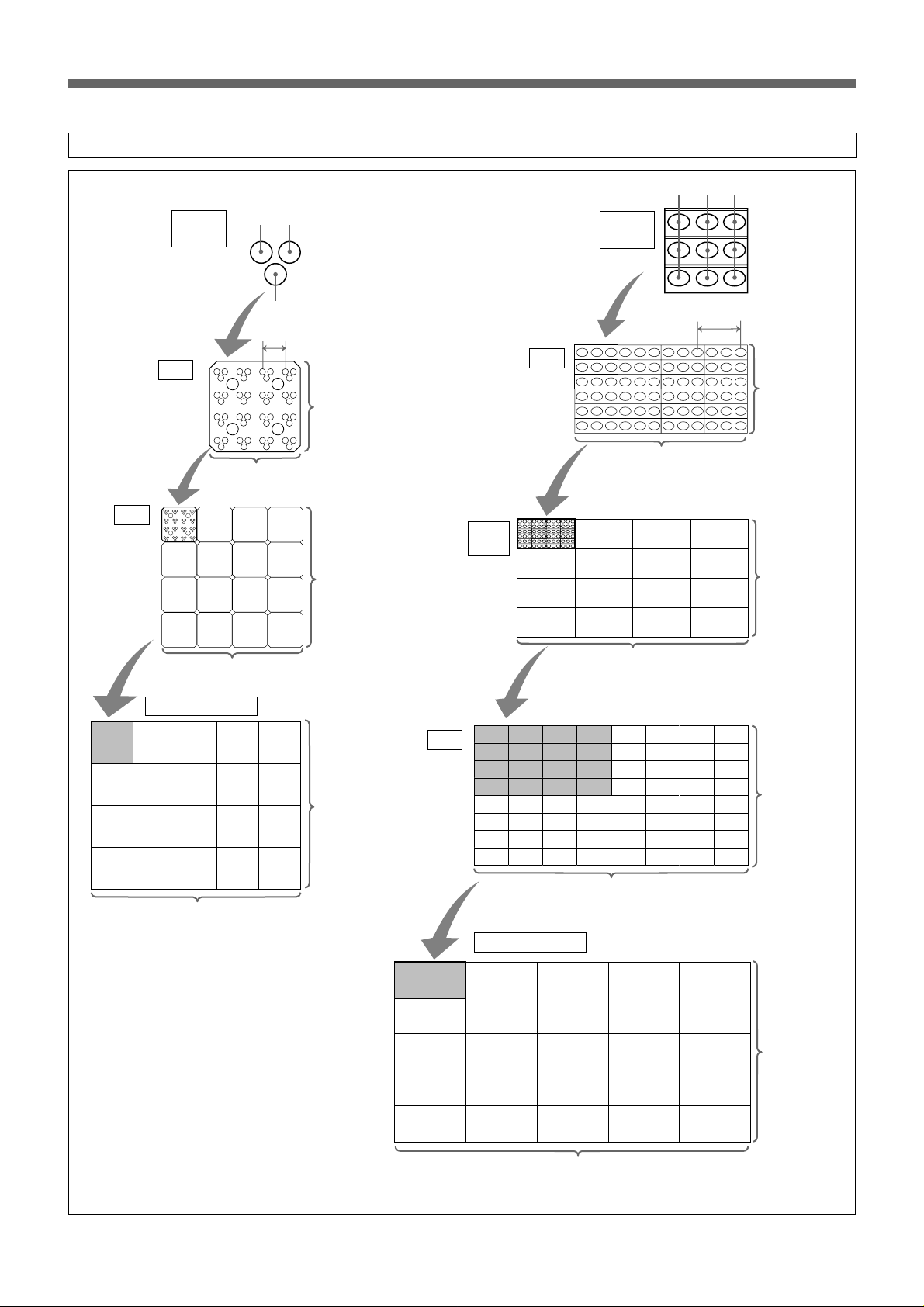
LED type
LDU-15 series
Cell
Unit
RGB trio
(dot)
GBR
Picture element pitch
4 dots
4 dots
4 cells (16 dots)
LDU-30 series
Front
panel
BRG
RGB trio
(dot)
Picture element pitch
Cell
2 dots
4 dots
4 cells
(8 dots)
4 cells (16 dots)
JumboTron screen
NTSC: max. 40 units (160 cells = 640 dots)
PAL: max. 48 units (192 cells = 768 dots)
NTSC:
max. 30 units
(120 cells = 480
dots)
PAL:
max. 36 units
(144 cells = 576
dots)
4 cells (16 dots)
Unit
2 panels
(16 dots)
2 panels (32 dots)
JumboTron screen
NTSC:
max. 30 units
(480 dots)
PAL:
max. 36 units
(576 dots)
NTSC: max. 20 units (640 dots)
PAL: max. 24 units (768 dots)
7
Overview of the JumboTron System
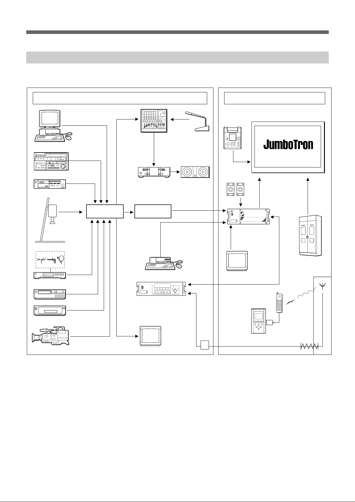
Configuration of the JumboTron system
The following is the suggested configuration of the JumboTron system.
Computer
VCR
Still image player
Video presenter
Control room
Audio mixer
Switcher
Microphone
Audio amplifier Speaker system
Frame
synchronizer
JME-UA200
unit alignment
controller
JTA-LS200
ABC sensor
unit
JTC-P200 image
control unit (ICU)
Screen site
JumboTron screen
Power source
TV tuner
Video disc player
DVD player
Video camera
Computer
JTC-C200 ICU
controller
Monitor
Modem
Monitor
JME-SA200
screen
alignment
controller
Digital
data
card
Cellular
phone
Public
telephone
line
8

Features
The JME-UA200 unit alignment controller is designed to adjust the
luminance of a JumboTron display unit, cell or pixel and to check their
operations.
The main functions of the JME-UA200 are as follows:
Eleven types of test signals
The built-in test signal generator of the controller displays eleven types of
test signals, allowing you to check various circuits and functions of a
JumboTron display unit.
Luminance adjustment of a cell and pixel as well as the whole unit
You can specify a cell or pixel (a single light emitting element of R, G and
B) which composes a JumboTron display unit and adjust its lumincance.
This allows you to obtain luminance uniformity of the whole screen.
Automatic luminance adjustment
After measuring the data of a cell which is emitting light correctly using a
unit alignment sensor (not supplied), you can adjust other cells
automatically to the same data as the correct cell.
Function check of a JumboTron display unit
You can check whether a JumboTron display unit is operating properly, or
check the current conditions of a unit.
Demonstration
The controller can display a test signal automatically on a small screen,
which is a combination of several units (up to 16 units), for a
demonstration.
9
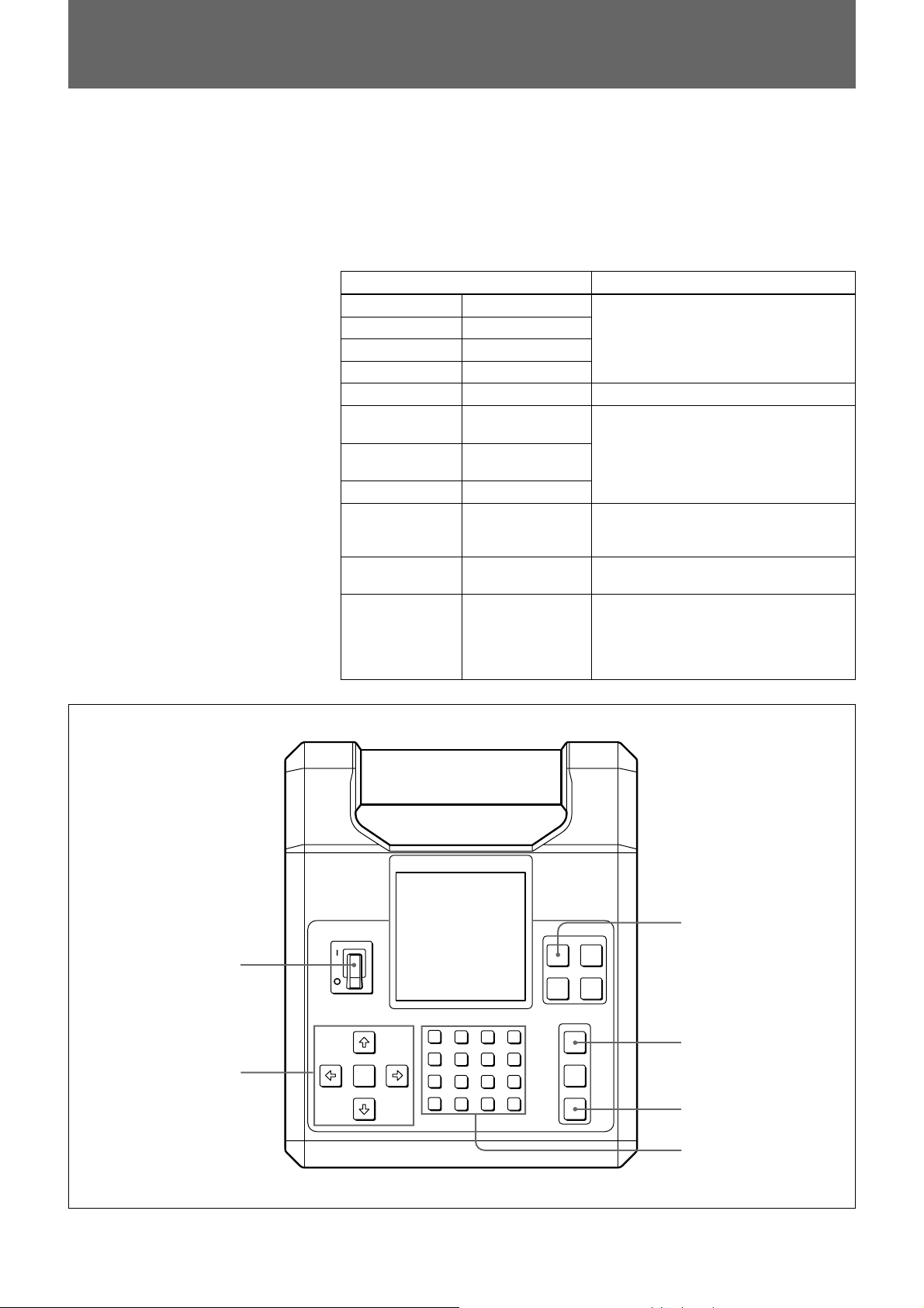
Locations and Functions of Parts and Controls
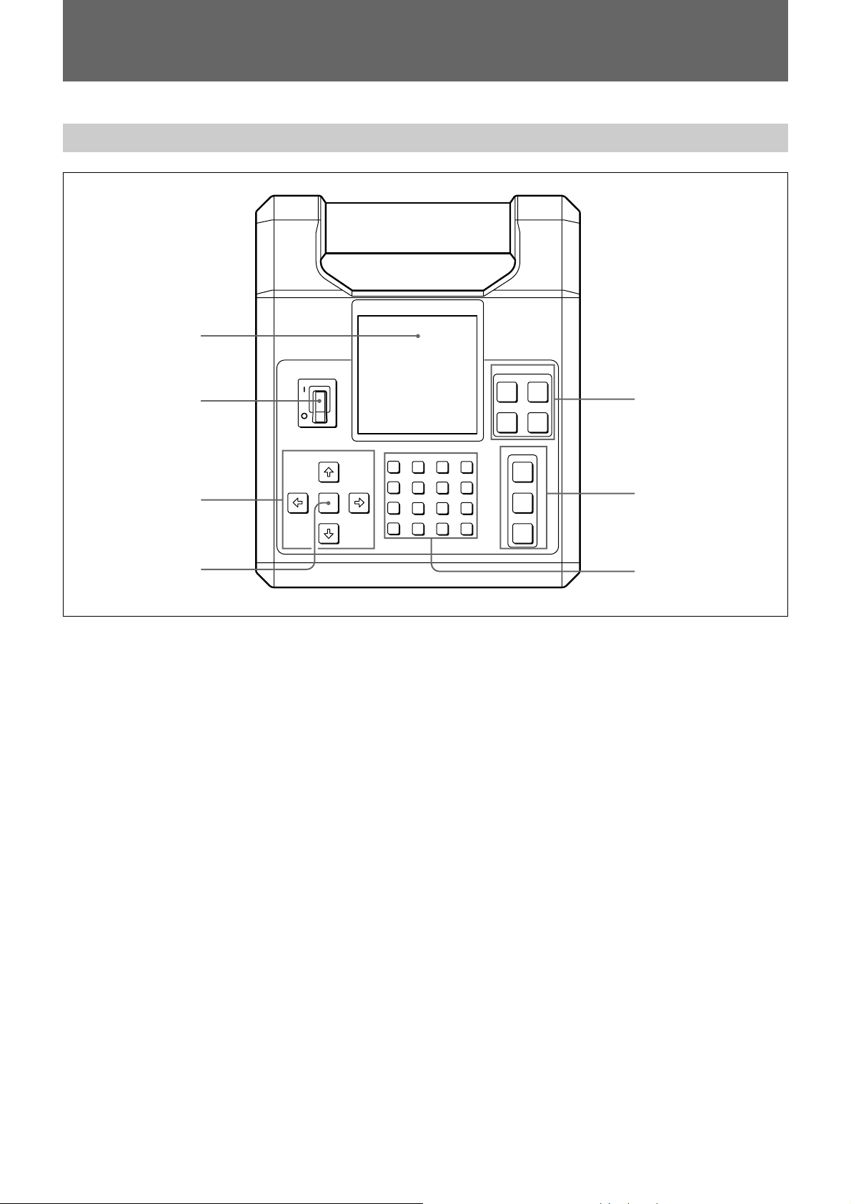
Front panel
1
MODE
SPG ADJUST
2
UNIT
CONTROL
DEMO
5
CURSOR
HOLD
3
CDEF
89AB
4567
0123
4
1 Display window
2 POWER ON/OFF switch
Turns the unit alignment controller on or off.
3 CURSOR ◊/√/∫/ı buttons
Move the cursor of the menu in the display window or
change the data.
4 HOLD button
Confirms the selected unit, cell or pixel to be adjusted.
5 MODE select buttons
SPG (Signal Pattern Generator) button: Displays a
test signal on a JumboTron display unit. You can
select and display the desired signal among eleven
signals; WHITE, BLUE, RED, GREEN, STAIR
STEP, COLOR BAR-V (vertical color bar), COLOR
BAR-H (horizontal color bar), CHARACTERS,
BEAM BLANKING, TEST and RASTER.
OPERATION
SETUP
WRITE
ENTER
6
7
DEMO (demonstration) button: Used for the
demonstration function.
6 OPERATION buttons
SETUP button: Changes the on-screen menu in the
display window.
WRITE button: Stores the adjusted data into
memory when adjusting the luminance manually.
ENTER button: Confirms the data value input with
the numeric buttons, or executes a specified operation.
7 Numeric buttons
Inputs the data in hexadecimal.
ADJUST button: Adjusts the luminance of a
JumboTron display unit.
UNIT CONTROL button: Checks the functions of a
JumboTron display unit.
10
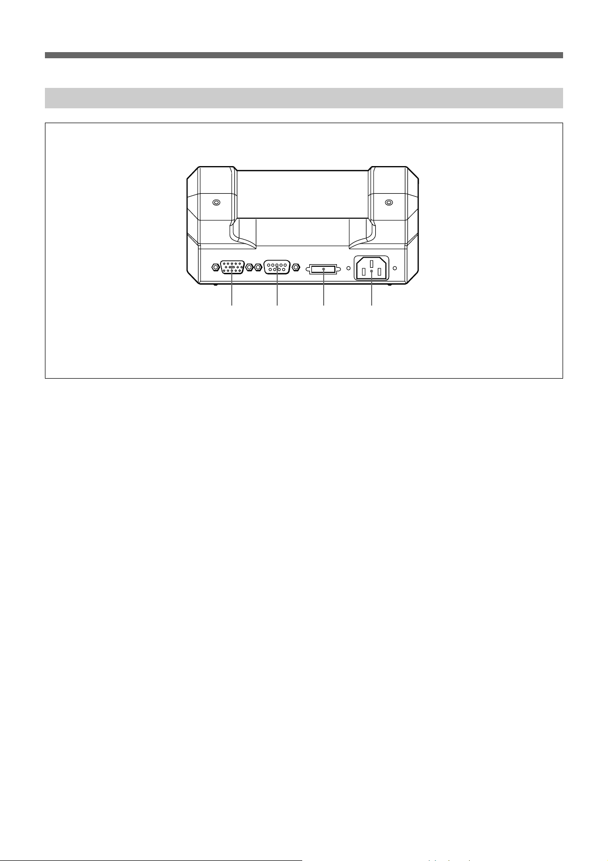
Rear panel
SIGNAL OUT COM SENSOR
123 4
1 SIGNAL OUT connector (D-sub 15-pin)
Connect a JumboTron display unit to be adjusted.
2 COM connector (D-sub 9-pin)
Connect a computer to display the data for
demonstration.
3 SENSOR connector (Half-pitch 20-pin)
Connect a unit alignment sensor (not supplied).
4 AC IN connector
Connect the AC power supply of 100–240 V.
Use the supplied AC power cord which fits the AC
outlet in your area.
AC IN
11
Connections
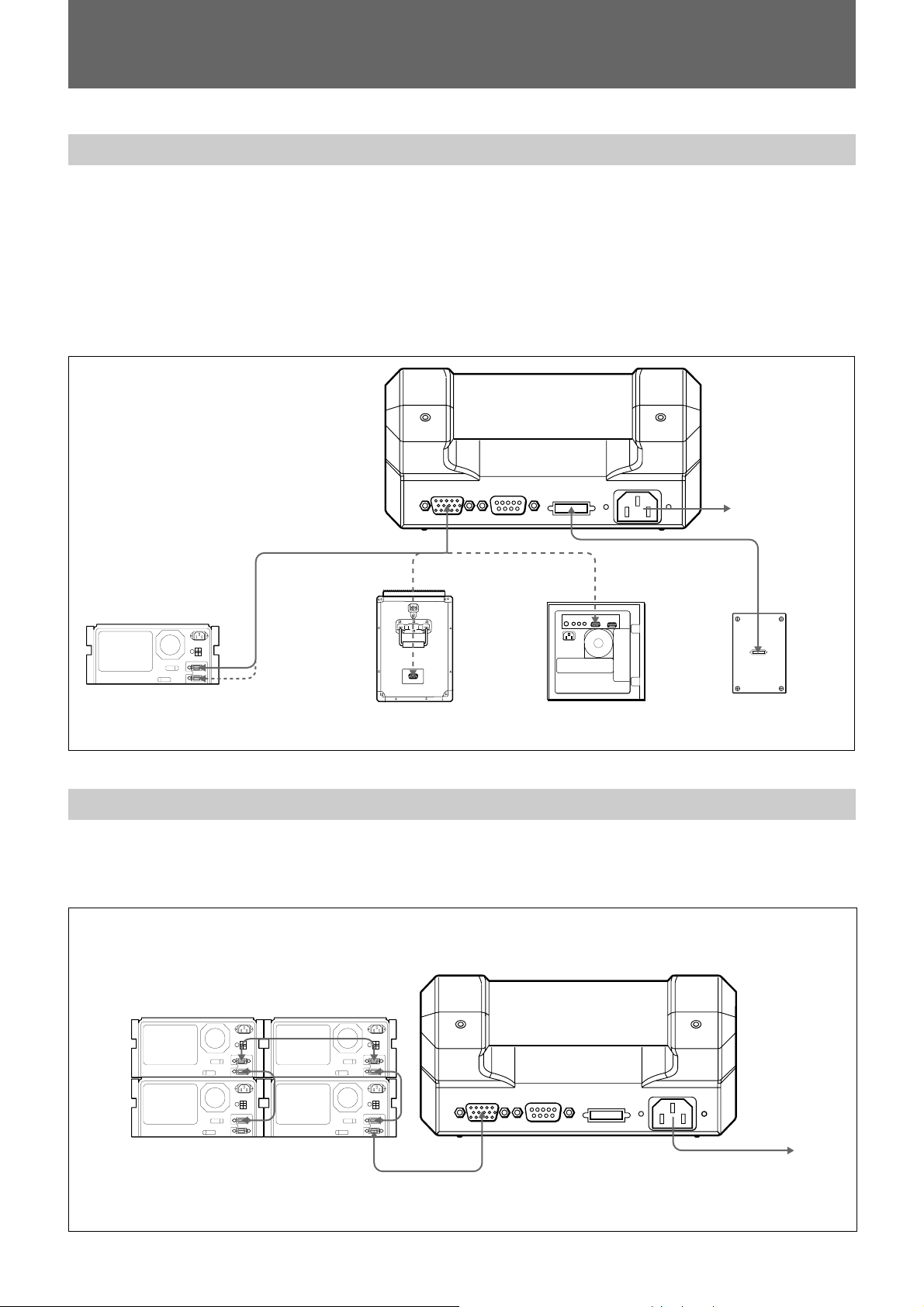
Connecting a JumboTron display unit
Connect a JumboTron display unit to the SIGNAL OUT connector.
When measuring the luminance or making an automatic luminance
adjustment, connect a unit alignment sensor (not supplied) to the SENSOR
connector.
Be sure to turn off the power of the controller before connecting the
sensor.
For details, see the Operating Instructions supplied with the unit alignment
sensor.
to 100–240 V AC
SENSOR
JTU-35 JumboTron
display unit (rear)
SIGNAL OUT
JME-US30L unit alignment
sensor box (side)
Connecting several JumboTron display units
You can combine several units as a small screen and connect them to the
controller for a simple demonstration. Press the DEMO button on the
controller to perform demonstration. Up to 16 units can be connected.
LDU-15 JumboTron
display unit (rear)
Unit alignment
sensor
(not supplied)
12
Screen for demonstration (rear)
SIGNAL OUT
to 100–240 V AC
Displaying a Test Signal on a JumboTron Display Unit
You can display eleven types of test signals on a JumboTron display unit.
Use this mode to clear the cause of the malfunctions of a unit or to check
the operation of a unit, cell or pixel after replacing or adjusting it.
After selecting the type of the test signal, you can specify precisely the
luminance, brightness, scroll speed and color bar width of each test signal.
The types of the test signals and their functions are described below.
Type of test signal
WHITE
BLUE
RED
GREEN
STAIR STEP
COLOR BAR-V
COLOR BAR-H
CHARACTERS
BEAM BLANKING
TEST
RASTER
White signal
Blue signal
Red signal
Green signal
Uniform bit signal
Vertical color bar
signal
Horizontal color bar
signal
Character signal
Pattern with
alternate line
blanking
Scrolls all the test
signals.
Adjusts the
luminance of red,
green and blue,
separately in the
range of 256 levels.
Operations and circuits to be checked
Uniformity of pixel light emission, etc.
Bit errors, etc.
Timing of data latch, etc.
Cathode switching circuit
All-round check of a JumboTron display
unit or a cell
Characteristics of pixel light emission,
etc.
POWER switch
CURSOR ◊/√/∫/ı
buttons
SPG button
SETUP button
ENTER button
Numeric buttons
13
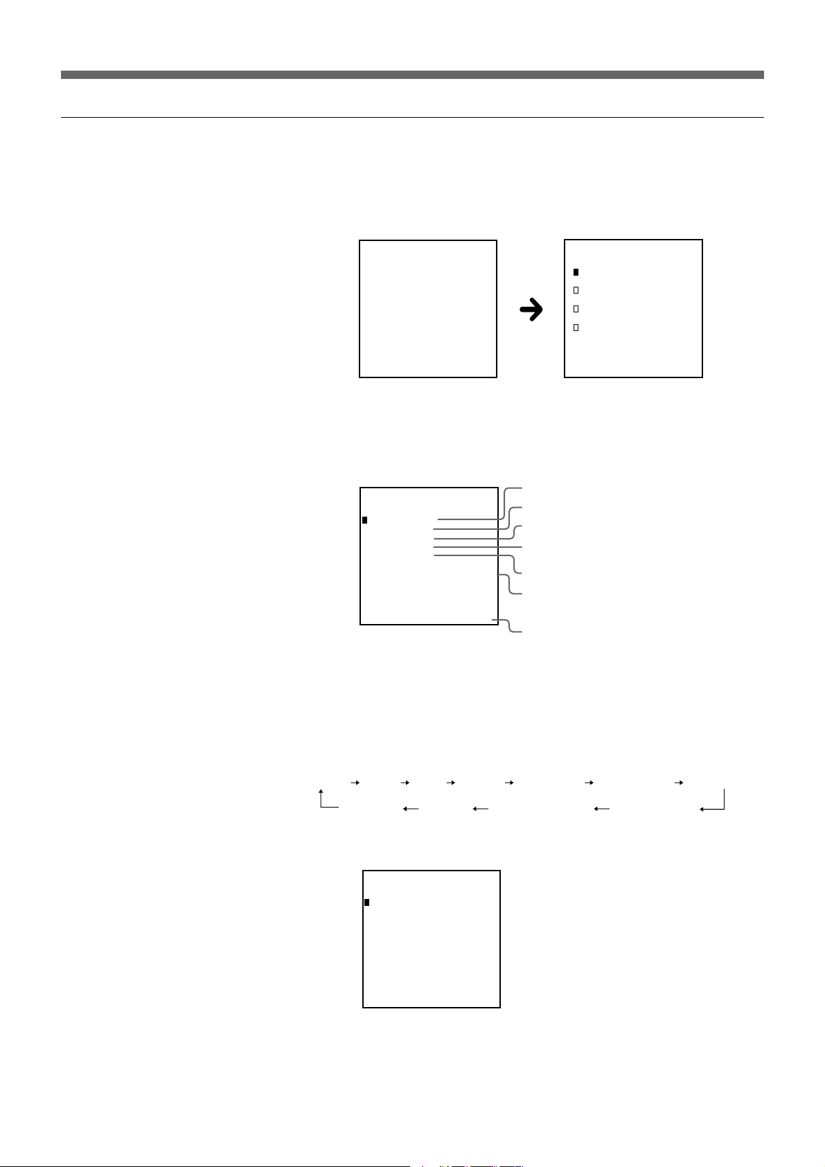
Displaying a Test Signal on a JumboTron Display Unit
1 Selecting the test signal to be displayed
1 Set the POWER switch to ON.
The title menu appears in the display window, then the display changes
to the UNIT type select menu.
Title menu UNIT type select menu
SONY
JumboTron
JME-UA200
ver X.X.X
Select UNIT Type
JTU-35 Series
JTU-17 Series
LDU-15 Series
LDU-30 Series
G30 Series
2 Press the ◊ or √ button to select the type of the JumboTron display
unit, and press the ENTER button.
3 Press the SPG button.
SPG Mode
SPG:WHITE
LUM:07F
BRT: 07
SPD: -WID: --
B/07F R/07F G/07F
UNIT TYPE:JTU-35
Type of test signal
Current luminance
Current brightness
Scroll speed
Color bar width
Luminance of R, G and B of the cell in the
upper left corner of the unit (The data is
displayed in hexadecimal.)
JumboTron display unit type
4 Select the signal to be displayed with the ∫ or ı button or the 0 to A
numeric buttons.
The test signal mode changes in the following order each time you
press the ∫ button. (Pressing the ı button changes the mode in the
reverse order.) You can also select the test signal mode by pressing the
button in brackets.
WHITE [0] BLUE [1] RED [2] GREEN [3] STAIR STEP [4] COLOR BAR-V [5] COLOR BAR-H [6]
RASTER [A] TEST [9] BEAM BLANKING [8] CHARACTERS [7]
Example: Selecting COLOR BAR-V by pressing ∫ or ı button or
numberic button 5.
SPG Mode
SPG:COLOR BAR-V
LUM:07F
BRT: 07
SPD: 03
WID: 01
UNIT TYPE:JTU-35
5 Press the ENTER button.
The selected test signal is displayed on the JumboTron display unit.
14
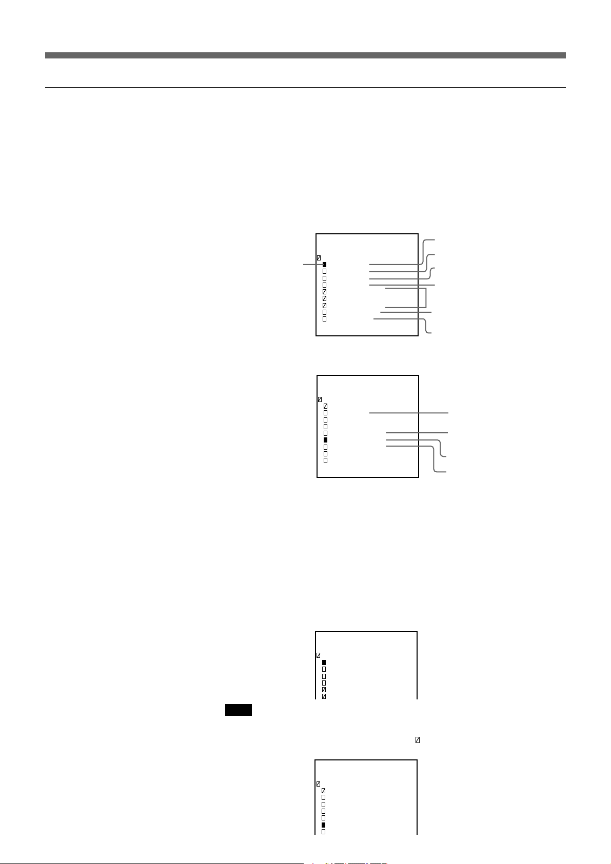
2 Specifying the luminance, brightness, scroll speed and color bar width of the
selected test signal
Specify after displaying the test signal on the JumboTron display unit by
steps 1 to 5 above.
6 Press the SETUP button.
The items to be specified and their current data (in hexadecimal)
appear in the display window.
Items to be specified
SPG Set Up
SPG:COLOR BAR-V
Cursor
LUM:07F
BRT: 07
SPD: 03
WID: 01
BLUE :07F
RED :07F
GREEN :07F
CLK :NTSC
LINE:064
UNIT TYPE:JTU-35
When you select RASTER in step 4, the following display appears.
SPG Set Up
SPG:RASTER
LUM:###
BRT: 07
SPD: -WID: -BLUE :07F
RED :052
GREEN :02A
CLK :NTSC
LINE:064
UNIT TYPE:JTU-35
Luminance
Brightness
Scroll speed
Color bar width
Items to be specified in
RASTER display mode
Clock of the output signal
Number of display lines
Items to be specified
Brightness
Luminance of blue
Luminance of red
Luminance of green
7 Select the item to be specified with the ◊ or √ button.
8 Change the data by pressing the ∫ or ı button or the numeric buttons.
• Each time you press the ∫ button, the level increases by 1, and
pressing the ı button decreases the level.
• You can also change the level by pressing the numeric buttons that
correspond to its level (for example, press 0, 7 and F to set the level to
7F).
Example: Setting LUM (luminance) to 7F.
SPG Set Up
SPG:COLOR BAR-V
LUM:07F
BRT: OA
SPD: 03
WID: 01
BLUE :07F
RED :07F
Note
There are some items that cannot be specified according to the test signals.
The cursors of these items are shown as “
shown as “– –” or “###”.
SPG Set Up
SPG:RASTER
LUM:###
BRT: 07
SPD: -WID: -BLUE :07F
RED :052
GREEN :02A
”, and the levels of the data are
(Continued)
15
Displaying a Test Signal on a JumboTron Display Unit
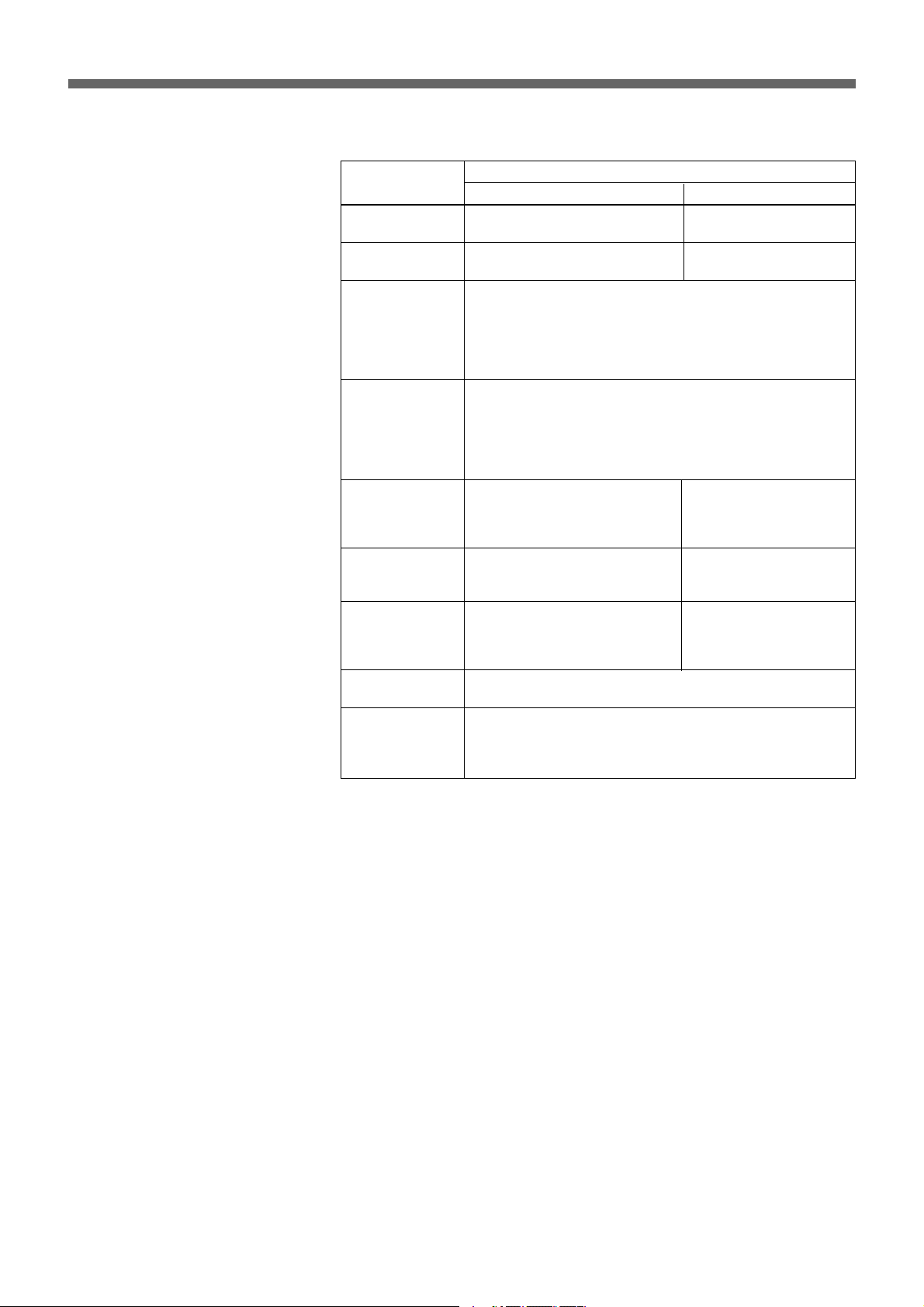
Items to be specified
Items
LUM (Luminance)
BRT (Brightness)
SPD (Scroll
speed)
WID (Vertical or
horizontal color
bar width)
BLUE (Luminance
of blue in
RASTER display
mode)
RED (Luminance
of red in RASTER
display mode)
GREEN
(Luminance of
green in RASTER
display mode)
CLK (Clock of the
output signal)
LINE (Number of
display lines)
Adjustable range
JTU-35, JTU-17
256 levels in the range from 00
to FF
16 levels in the range from 00 to
0F
00: Scrolls with each press of the ENTER button
01: Scrolls at every 1/60 seconds
02: Scrolls at every 1/3 seconds
03: Scrolls at every second
04: Scrolls at every 2 seconds
05: Scrolls at every 4 seconds
01: 1 line
02: 2 lines
03: 4 lines
04: 8 lines
05: 16 lines
06: 32 lines
256 levels in the range from 000
to 0FF
256 levels in the range from 000
to 0FF
256 levels in the range from 000
to 0FF
Output timing with the NTSC or PAL signal
016: output signal with 16 lines
064: output signal with 64 lines
128: output signal with 128 lines
256: output signal with 256 lines
1)
LDU-15, LDU-30
1024 levels in the range
from 000 to 3FF
16 levels in the range
from 00 to 0F
1024 levels in the range
from 000 to 3FF
1024 levels in the range
from 000 to 3FF
1024 levels in the range
from 000 to 3FF
•If you change the CLK setting while the JumboTron display unit is in
operation, the unit cannot receive the signal from this controller. In this
case, disconnect the unit, then turn on back the power of the unit.
•If you increase the number of display lines with SPD (scroll speed) set to
01, the JumboTron display unit cannot receive the signal from the
controller correctly. If you want to increase the scroll speed, specify the
less number of display lines.
..........................................................................................................................................................................................................
1) Line
The width of one line of the color bar is 1 dot (a set of R, G
and B). Therefore, if you set a color bar width to 03 (4
lines), the color bar width is 4 dots.
16
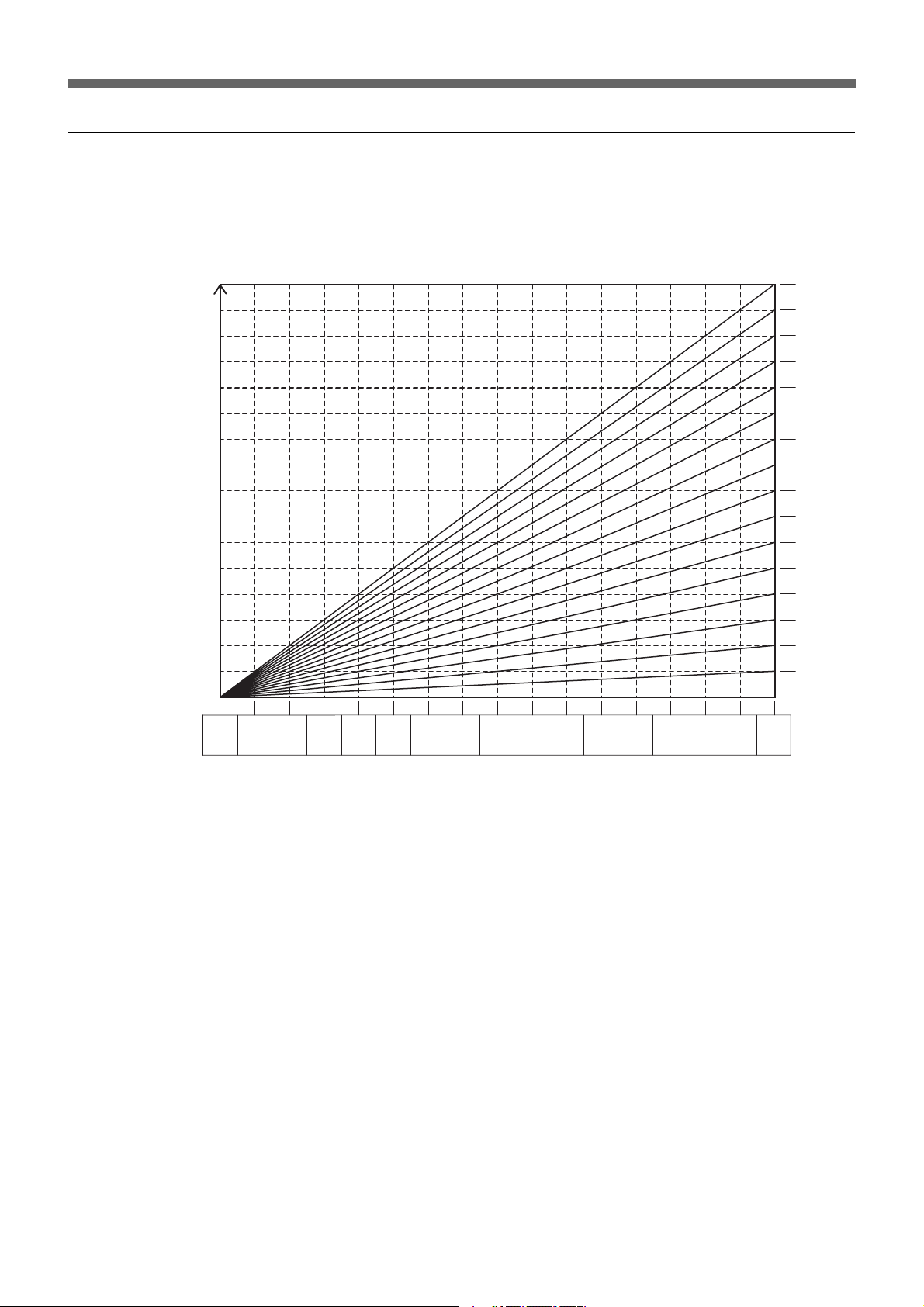
Relation between luminance and brightness
BRT (brightness) indicates the adjustable range of the brightness for a
JumboTron display unit emitted. LUM (luminance) shows the tone with
the set brightness.
Brightness of a
JumboTron
display unit
BRT
BRT 0F
BRT 0E
BRT 0D
BRT 0C
BRT 0B
BRT 0A
BRT 09
BRT 08
BRT 07
BRT 06
BRT 05
BRT 04
BRT 03
BRT 02
BRT 01
BRT 00
LUM
JTU-35/JTU-17 series
LDU-15/LDU-30 series
00001040208030C040
1005014060180
70
80
1C0
20090240A0280
B0
C0
2C0
300D0340E0380F03C0FF3FF
17
 Loading...