

Sony JCC-VIR978D Quick Start Manual
JCC-VIR978D
1/3” Color SONY IR Dome Camera
FEATURES
z Color camera with SONY 1/3“ Super HAD High Res. CCD
sensor.
z Employs SONY Digital Signal Processor (DSP) IC for image
control.
z Pixel number: NTSC=380K / PAL=440K
z High sensitivity, low smear, high anti-blooming.
z Auto Electronic Shutter (AES), Auto Gain Control (AGC),
Auto Iris (AI), Back Light Compensation (BLC), Auto White
Balance (AWB), Flickerless mode (FL).
z Built-in Vari-focal type DC-drive auto iris lens.
z Furnished with power cable and video cable.
z Low power consumption.
z Easy to install, easy to use, aesthetic.
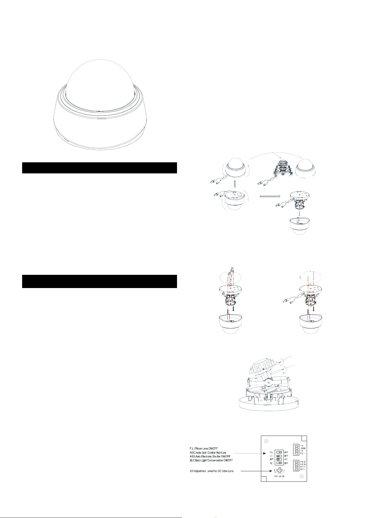
INSTALLATION INSTRUCTIONS
1. Please select the most suitable position on the wall or ceiling
to install the camera.
2. Rotate the dome housing counterclockwise to remove it
from the mounting base (shown on fig. 1).
3. Set the mounting base onto the wall or ceiling and center it
over the mounting hole, using the two retaining screws for
the main body supplied by the appurtenance bag (shown
on fig. 1).
4. The unit has a factory installed back conduit entry and one
may adjust the cables to side conduit entry according to
installation requirement (shown on fig. 2).
5. Once the picture appears on the monitor, open the cover
adjust the lens wrench of “NEAR←→FAR” to get the view
zoom that you desire, then adjust the focus wrench of the
Lens to obtain the best picture. After adjustment, tighten
this two wrench both. (shown on fig. 3).
6. DIP Switch Setting (shown on fig. 4).
z Flickerless Function
Set switch-OFF/ F.L. to Flicker to enable flickerless
function, in this mode, the switch-AES/ OFF is auto
disabled.
z AGC-Hi/ AGC-Lo Function
Adjust the switch to AGC indicates AGC-Hi and OFF
indicates AGC-Low. This switch setting to High or Low
of the AGC maximum gain. AGC-Hi mode--The
maximum AGC gain is approximately 26dB. AGC-Lo
mode--The maximum AGC gain is approximately 16dB.
7. BLC FUNCTION
Set Switch-OFF/ BLC to BLC to enable Back Light
Compensation (BLC) function.
8. For lens adjustment, move the camera body (some model
types limits the PCB board to180°rotational adjustment)
and set the focus by turning the lens to the left or right
direction. When the camera focus adjustment has been
completed, rotate the dome housing clockwise to secure it
to the mounting base (shown on fig. 5).
9. Connect the Video Output to the monitor or other video
device through a 75 Ohms type coaxial cable. Connect the
AC/ DC-Terminator with power source (shown on fig. 6).
Note! The inner parts may differ depending on the camera model type
Fig. 1: Remove the dome
Mounting Base Dome Housing
Fig. 2: Cable outlet choice
or
OR
Fig. 3: Adjust the camera lens
Zoom Adjustme nt
TELE
FAR
Focal Adjustment
WIDE
Fig. 4: Configure the camera
NEAR
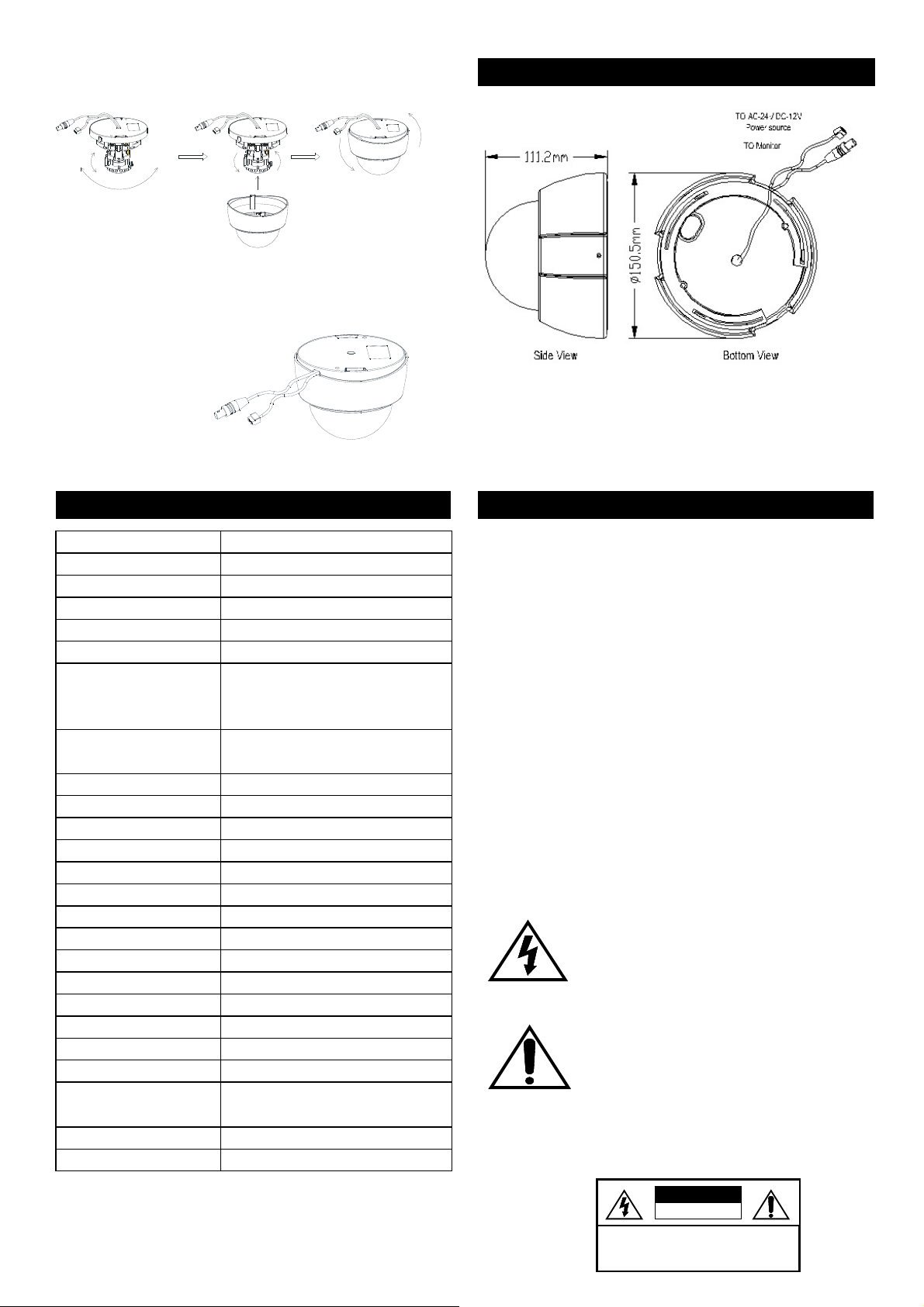
Fig.5:Replacethedomecover
Fig.6:Installthebracket
DIMENSIONS
SPECIFICATIONS SAFETY WARNI NGS
Model No. JCC-VIR978D
Image Device SONY 1/3“ Hi-Res. Super HAD CCD sensor
Picture Elements NTSC:811(H ) X 508(V), PAL: 795(H) X 596(V)
Horizontal Resolution 470 horizontal lines
Minimum Illumination 0.3 LUX @ F2.0, 0 Lux ( IR On )
S/N Ratio More than 48dB
Auto Electronic Shutter NTSC: 1/60s~1/100,000s,
Flickerless Mode NTSC: 1/100s,
Gamma Characteristic 0.45
Iris Control DC Drive
Lens Furnished 3.7~12mm / F1.6 Vari-Focal with DC
White Balance Auto
Gain Control Hi /Low
Back Light Compensation ON/OFF
Synchronous System Internal, Negative sync.
Video Output 1 Vp-p / 75 Ohms.
Scanning System Interlace 2:1
Infrared Luminary 24 pieces IR-LED,Life:600hrs
Wavelength 850nm
Illuminate Distance 20M
Illuminator Active Limit 5Lux
Power Supply DC12V
Power Consumption
(with DC Driver Lens
Storage Temp. -20 to 6℃ 0 (℃ -4 to 114 )℉℉
Operating Temp. -10 to 50 (14 to 122 )℃℃℉ ℉
To Monit or
To AC-24V/DC-12V Power Source
PAL: 1/50s~1/110,000s
ON/OFF switchable.
PAL: 1/120s ON/OFF switchable.
400mA(IR ON)Max
200 mA(IR OFF) Max
1. Do not open the cover, it may cause electric shock. Ask a
qualified service person for maintenance when you
encounter any problems.
2. Installed the camera away from TV, radio transmitter,
magnet, electric motor, transformer, audio speakers
because the magnetic fields generate from above devices
will distort the video image.
3. Place this camera on a solid base. Installed the camera
away from stoves or other heat generating devices as the
high temperature could cause deformation, discoloration or
other damages of the camera. Install the camera at where
the temperature range will stay between 0°C~50°C
(32°F~122°F)
4. Do not expose and operate the camera in the rain and
humid areas.
5. Only use soft dry cloth to clean the camera. Also use lens
tissue or cotton tipped applicator and ethanol to clean CCD
sensor and camera lens.
6. When the camera is not in use, put the cover cap on the lens
mount. Please do not touch the surface of CCD by bare
hand.
The lightning flash with arrowhead symbol, within an equilateral triangle, is
interned to alert the user to the presence of uninsulated “dangerous
voltage” within the product’s enclosure that may be of sufficient magnitude
to constitute a risk of electric shock to persons.
The exclamation point within an equilateral tr iangle is intended to a lert the
user to the presence of important operating and maintenance (servicing)
instructions in the literature accompanying the appliance.
▲ Before attempting to connect this product, please read and
keep this manual for future use.
CAUTION:
TO REDUCE THE RISK OF ELECTRIC SHOCK, DO NOT REMOVE
COVER (OR BACK), NO USER SERVICEABLE PARTS INSIDE.
REFER SERVICING TO QUALIFIED SERVICE PERSONNEL.
CAUTION
RISK OF ELECTRIC SHOCK
DO NOT OPEN
 Loading...