

Page 1

COMPACT PLAYER
J-10
J-10SDI
J-30
J-30SDI
(J-30/30SDI)
(J-30/30SDI)
OPERATION MANUAL
1st Edition
[English]
Page 2
WARNING
To prevent fire or shock hazard, do not
expose the unit to rain or moisture.
To avoid electrical shock, do not open the
cabinet. Refer servicing to qualified
personnel only.
WARNING
THIS APPARATUS MUST BE EARTHED.
This symbol is intended to alert the user to the
presence of uninsulated “dangerous voltage”
within the product’s enclosure that may be of
sufficient magnitude to constitute a risk of
electric shock to persons.
This symbol is intended to alert the user to the
presence of important operating and
maintenance (servicing) instructions in the
literature accompanying the appliance.
• Do not defeat the safety purpose of the polarized or
grounding-type plug. A polarized plug has two blades with
one wider than the other. A grounding type plug has two
blades and a third grounding prong. The wide blade or the
third prong are provided for your safety. If the provided plug
does not fit into your outlet, consult an electrician for
replacement of the obsolete outlet.
• Protect the power cord from being walked on or pinched
particularly at plugs, convenience receptacles, and the
point where they exit from the apparatus.
• Only use attachments/accessories specified by the
manufacturer.
• Use only with the cart, stand, tripod, bracket, or
table specified by the manufacturer, or sold with
the apparatus. When a cart is used, use caution
when moving the cart/apparatus combination to
avoid injury from tip-over.
• Unplug this apparatus during lightning storms or when
unused for long periods of time.
• Refer all servicing to qualified service personnel. Servicing
is required when the apparatus has been damaged in any
way, such as power-supply cord or plug is damaged, liquid
has been spilled or objects have fallen into the apparatus,
the apparatus has been exposed to rain or moisture, does
not operate normally, or has been dropped.
WARNING: THIS WARNING IS APPLICABLE FOR USA
ONLY.
If used in USA, use the UL LISTED power cord specified
below.
DO NOT USE ANY OTHER POWER CORD.
Plug Cap Parallel blade with ground pin (NEMA 5-15P
Configuration)
Cord Type SJT, three 16 or 18 AWG wires
Length Minimum 1.5m
Rating Minimum 10A, 125V
Important Safety Instructions
• Read these instructions.
•Keep these instructions.
• Heed all warnings.
•Follow all instructions.
• Do not use this apparatus near water.
• Clean only with dry cloth.
• Do not block any ventilation openings. Install in accordance
with the manufacturer’s instructions.
• Do not install near any heat sources such as radiators, heat
registers, stoves, or other apparatus (including amplifiers)
that produce heat.
Using this unit at a voltage other than 120V may require the
use of a different line cord or attachment plug, or both.
To reduce the risk of fire or electric shock, refer servicing to
qualified service personnel.
WARNING: THIS WARNING IS APPLICABLE FOR OTHER
COUNTRIES.
1. Use the approved Power Cord (3-core mains lead) /
Appliance Connector / Plug with earthing-contacts that
conforms to the safety regulations of each country if
applicable.
2. Use the Power Cord (3-core mains lead) / Appliance
Connector / Plug conforming to the proper ratings
(Voltage, Ampere).
If you have questions on the use of the above Power Cord /
Appliance Connector / Plug, please consult a qualified
service personnel.
Page 3

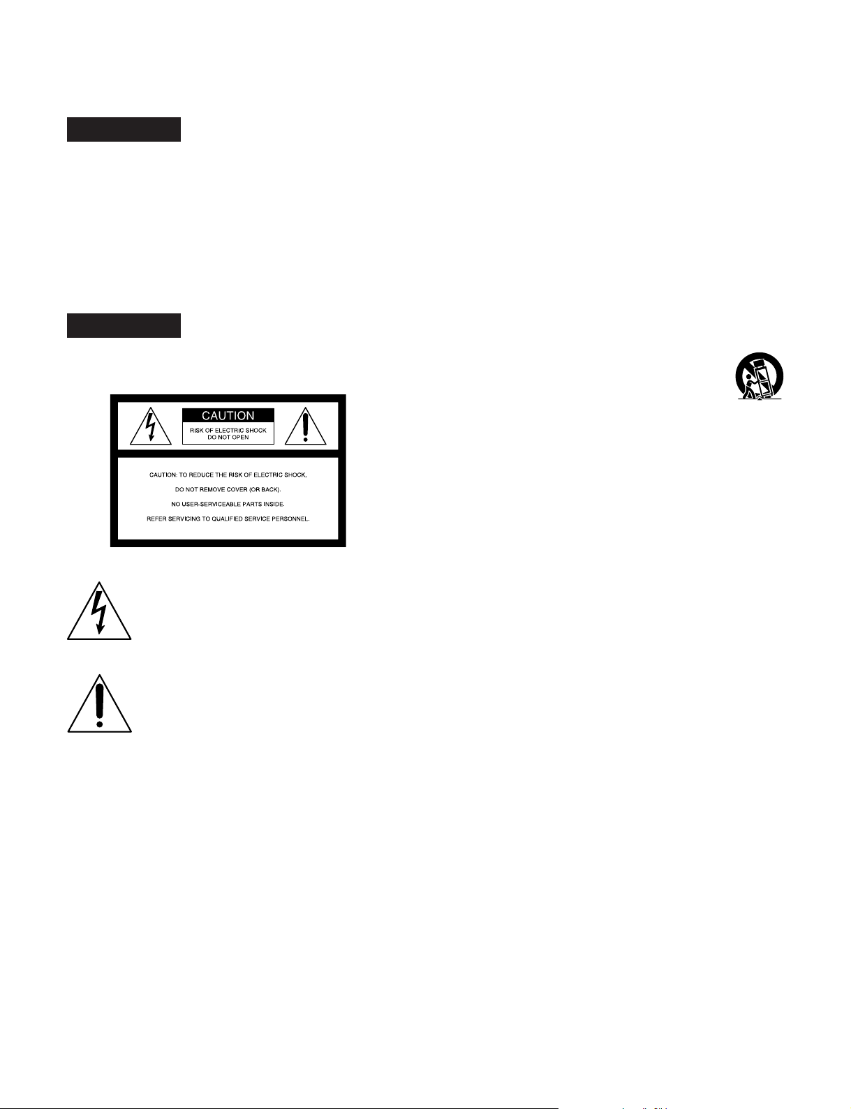
CAUTION
Danger of explosion if battery is incorrectly replaced.
Replace only with the same or equivalent type recommended
by the manufacturer. Dispose of used batteries according to
the manufacturer’s instructions.
CAUTION
The apparatus shall not be exposed to dripping or splashing
and no objects filled with liquid, such as vases, shall be
placed on the apparatus.
Do not install the appliance in a confined space, such as
book case or built-in cabinet.
AVERTISSEMENT
Afin d’éviter tout risque d’incendie ou
d’électrocution, ne pas exposer cet
appareil à la pluie ou à l’humidité.
Afin d’écarter tout risque d’électrocution,
garder le coffret fermé. Ne confier
l’entretien de l’appareil qu’à un personnel
qualifié.
AVERTISSEMENT
CAUTION
The unit is not disconnected from the AC power source
(mains) as long as it is connected to the wall outlet, even if
the unit itself has been turned off.
For the customers in the USA
This equipment has been tested and found to comply with the
limits for a Class A digital device, pursuant to Part 15 of the
FCC Rules. These limits are designed to provide reasonable
protection against harmful interference when the equipment
is operated in a commercial environment. This equipment
generates, uses, and can radiate radio frequency energy
and, if not installed and used in accordance with the
instruction manual, may cause harmful interference to radio
communications. Operation of this equipment in a residential
area is likely to cause harmful interference in which case the
user will be required to correct the interference at his own
expense.
You are cautioned that any changes or modifications not
expressly approved in this manual could void your authority
to operate this equipment.
The shielded interface cable recommended in this manual
must be used with this equipment in order to comply with the
limits for a digital device pursuant to Subpart B of Part 15 of
FCC Rules.
For the customers in Europe
This product with the CE marking complies with both the
EMC Directive (89/336/EEC) and the Low Voltage Directive
(73/23/EEC) issued by the Commission of the European
Community.
Compliance with these directives implies conformity to the
following European standards:
• EN60065: Product Safety
• EN55103-1: Electromagnetic Interference (Emission)
• EN55103-2: Electromagnetic Susceptibility (Immunity)
This product is intended for use in the following
Electromagnetic Environment(s):
E1 (residential), E2 (commercial and light industrial), E3
(urban outdoors) and E4 (controlled EMC environment, ex.
TV studio).
CET APPAREIL DOIT ETRE MIS A LA TERRE.
AVERTISSEMENT:
1. Utiliser le cordon d’alimentation approuvé (conducteur à
trois noyaux)/connecteur pour appareils approuvé / fiche
avec contacts de mise à la terre approuvée, qui est
conforme aux règles de sécurité de chaque pays, si
applicable.
2. Utiliser un cordon d’alimentation (conducteur à trois
noyaux)/connecteur pour appareils/fiche avec contacts de
mise à la terre conforme aux valeurs nominales correctes
(tension, ampérage).
Pour toute question concernant l’emploi du cordon
d’alimentation/connecteur pour appareils/fiche ci-dessus,
consulter un agent de service compétent.
ATTENTION
Il y a un risque d’explosion si la pile est mal insérée.
Remplacer la pile uniquement par une pile de même type ou
de type équivalent recommandé par le fabricant. Jeter les
piles usées conformément aux instructions du fabricant.
ATTENTION
Eviter d’exposer l’appareil à un égouttement ou à des
éclaboussures et ne placer aucun objet rempli de liquide,
comme un vase, sur l’appareil.
Ne pas installer l’appareil dans un endroit confiné, par
exemple une bibliothèque ou un placard encastré.
ATTENTION
Cet appareil n’est pas déconnecté de la source
d’alimentation secteur tant qu’il est raccordé à la prise
murale, même si l’appareil lui-même a été mis hors tension.
Page 4

Pour les clients européens
Ce produit portant la marque CE est conforme à la fois à la
Directive sur la compatibilité électromagnétique (EMC) (89/
336/CEE) et à la Directive sur les basses tensions (73/23/
CEE) émises par la Commission de la Communauté
européenne.
La conformité à ces directives implique la conformité aux
normes européennes suivantes:
• EN60065: Sécurité des produits
• EN55103-1: Interférences électromagnétiques (émission)
• EN55103-2: Sensibilité électromagnétique (immunité)
Ce produit est prévu pour être utilisé dans les
environnements électromagnétiques suivants:
E1 (résidentiel), E2 (commercial et industrie légère), E3
(urbain extérieur) et E4 (environnement EMC contrôlé ex.
studio de télévision).
WARNUNG
Um Feuergefahr und die Gefahr eines
elektrischen Schlages zu vermeiden, darf
das Gerät weder Regen noch Feuchtigkeit
ausgesetzt werden.
Um einen elektrischen Schlag zu
vermeiden, darf das Gehäuse nicht
geöffnet werden. Überlassen Sie
Wartungsarbeiten stets nur einem
Fachmann.
WARNUNG
DIESES GERÄT MUSS GEERDET WERDEN.
WARNUNG:
1. Es ist ein (dreiadriges) Netzkabel/Netzstecker mit
Erdungskontakt zu verwenden, der den
Sicherheitsbestimmungen vor Ort entspricht.
2. Es ist ein (dreiadriges) Netzkabel/Netzstecker mit
ausreichenden Anschlußwerten (Spannung/Strom) zu
verwenden.
ACHTUNG
Das Gerät ist nicht tropf- und spritzwassersicher, daher
dürfen keine mit Flüssigkeiten gefüllten Gegenstände, z. B.
Vasen, darauf abgestellt werden.
Das Gerät nicht an Orten aufstellen, z. B. in Bücherregalen
oder Einbauschränken, wo keine ausreichende Belüftung
gewährleistet ist.
ACHTUNG
Solange das Netzkabel an eine Netzsteckdose
angeschlossen ist, bleibt das Gerät auch im ausgeshalteten
Zustand mit dem Stromnetz verbunden.
Für Kunden in Europa
Dieses Produkt besitzt die CE-Kennzeichnung und erfüllt die
EMV-Direktive (89/336/EMG) der EG-Kommission als auch
die Direktive Niederspannung (73/23/EMG).
Angewandte Normen:
• EN60065: Produktsicherheit
• EN55103-1: Elektromagnetische Verträglichkeit
(Störaussendung)
• EN55103-2: Elektromagnetische Verträglichkeit
(Störfestigkeit)
für die folgenden elektromagnetischen Umgebungen:
E1 (Wohnbereich), E2 (kommerzieller und in beschränktem
maße industrieller Bereich), E3 (Stadtbereich im Freien) und
E4 (kontrollierter EMV-Bereich, z.B. Fernsehstudio).
Für Kunden in Deutschland
Entsorgungshinweis: Bitte werfen Sie nur entladene Batterien
in die Sammelboxen beim Handel oder den Kommunen.
Entladen sind Batterien in der Regel dann, wenn das Gerät
abschaltet und signalisiert „Batterie leer“ oder nach längerer
Gebrauchsdauer der Batterien „nicht mehr einwandfrei
funktioniert“. Um sicherzugehen, kleben Sie die Batteriepole
z.B. mit einem Klebestreifen ab oder geben Sie die Batterien
einzeln in einen Plastikbeutel.
Voor de klanten in Nederland
Bei Fragen zum Gebrauch des obigen Netzkabels/
Netzsteckers wenden Sie sich bitte an den technischen
Kundendienst.
VORSICHT
Es besteht Explosionsgefahr, wenn die Batterie inkorrekt
eingelegt wird.
Es darf nur eine identische oder eine vom Hersteller
empfohlene Batterie des gleichen Typs eingesetzt werden.
Entladene Batterien sind nach den Anweisungen des
Herstellers zu entsorgen.
Gooi de batterij niet weg, maar lever hem in als KCA
Page 5

Table of Contents
Chapter 1
Overview
Chapter 2
Location and Function
of Parts
Chapter 3
Preparations
Chapter 4
Playback
1-1 Before Using ....................................................................................1-1
1-2 Features ........................................................................................... 1-2
1-3 Sample System Configuration.......................................................1-4
2-1 Control Panel .................................................................................. 2-1
2-1-1 Display Section ......................................................................2-2
2-1-2 Search Control Section...........................................................2-6
2-1-3 Tape T ransport Control Section ............................................. 2-7
2-2 Connector Panel ............................................................................. 2-8
2-2-1 Connector Panel of the J-10/30 .............................................. 2-8
2-2-2 Connector Panel of the J-10SDI/30SDI ............................... 2-10
3-1 Installation ...................................................................................... 3-1
3-2 Cassettes ..........................................................................................3-2
4-1 Playback Procedures......................................................................4-1
4-1-1 Normal Playback ................................................................... 4-1
4-1-2 Playback in Jog Mode ........................................................... 4-2
4-1-3 Playback in Shuttle Mode .....................................................4-2
4-1-4 Noiseless Playback Function and Frame Step Playback
Function .................................................................................4-3
4-2 Superimposed Character Information ......................................... 4-5
4-3 Using the Remote Commander .....................................................4-6
4-3-1 How to Change the Lithium Battery ...................................... 4-6
4-3-2 Setting Menu .......................................................................... 4-6
4-3-3 Operating the Remote Commander........................................4-7
4-4 Operation via Computer (With the JZ-1 Software).................... 4-8
4-4-1 Capturing Images Using Shot Mark Data .............................. 4-8
Chapter 5
UMID Functions
Chapter 6
Essence Marks
Chapter 7
Setup Menu
5-1 Overview of UMID Functions .......................................................5-1
5-2 UMID Output and Display ............................................................ 5-2
5-2-1 UMID Output Settings........................................................... 5-2
5-2-2 UMID Display ....................................................................... 5-2
6-1 Overview of Essence Mark Functions .......................................... 6-1
6-2 Essence Mark Output .................................................................... 6-2
7-1 Menu System Configuration..........................................................7-1
7-2 Menu Operations............................................................................7-2
7-3 Basic Menu......................................................................................7-7
7-4 Extended Menu............................................................................. 7-10
Table of Contents 1
Page 6

Table of Contents
Chapter 8
Maintenance and
Inspection
Appendix
8-1 Removing a Cassette When Tape Slack Occurs........................... 8-1
8-2 Head Cleaning ................................................................................8-1
8-3 Moisture Condensation..................................................................8-2
8-4 Error Messages............................................................................... 8-3
8-5 Digital Hours Meter ....................................................................... 8-4
Specifications......................................................................................... A-1
2 Table of Contents
Page 7
Overview
1-1 Before Using
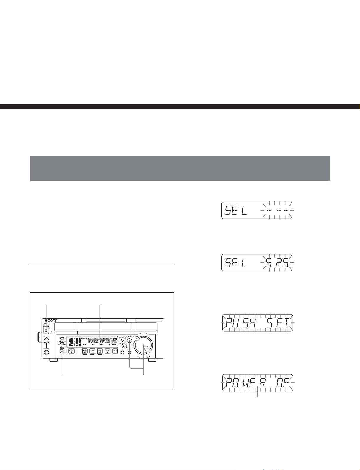
When using this unit for the first time, set the number
of scan lines to the NTSC (525 scan lines, field
frequency 60 Hz) system setting or to the PAL (625
scan lines, field frequency 50 Hz) system setting
according to the operating environment in which the
unit will be used. Otherwise, it will be impossible to
use this unit.
Chapter 1 Overview
Chapter 1
2 Holding down the JOG/SHUTTLE button, turn the
JOG/SHUTTLE dial to display “525” or “625”
next to “SEL”.
To set this unit for the NTSC (525/60) or
PAL (625/50) system
1,4
Time data display area
32
1 Turn the POWER switch on.
When you turn on this unit for the first time,
indication, “SEL ------” appears in the time data
display area.
3 Press the SET/MENU button.
Indication “PUSH SET” appears in the time data
display area.
4 Turn the POWER switch off, and then on again.
The indication in the time data display area
changes as shown in the figure below.
You can see “POWER OFF/ON” by scrolling the
indication.
This unit is set for the 525/60 or 625/50 system and
indicator 525 or 625 lights above the time data display
area to show the selected system.
Chapter 1 Overview 1-1
Page 8

Chapter 1 Overview
1-2 Features
The J-10/10SDI/30/30SDI (also referred to simply as
the unit(s) in this manual) are compact players based
1
on the
They play tapes recorded in conventional Betacam/
Betacam SP format.
Notes
•Since the unit does not have a dynamic tracking
•If you use a mobile radio machine with 5 W or larger
The following are some of the features of these units.
/2-inch tape format.
function, the tape may not replay correctly if the
recording pattern on the tape are disturbed.
output within 50 cm (19
playback image may be disturbed.
3
/4 inches) of this unit, the
Compatible format for playback
The unit can play tapes in the following formats:
•Digital Betacam format (J-30/30SDI only)
•MPEG IMX format (J-30/30SDI only)
•Betacam SX format
•Betacam/Betacam SP format
Playback compatibility with Betacam/
Betacam SP
The unit plays tapes recorded in the Betacam/Betacam
SP format. This makes for efficient use of existing
material in the Betacam/Betacam SP format.
Feeder function
This unit can be used not only as a Player but also as a
Feeder. Connected to a PC, the unit controls images
and feeds images to the PC via a remote connector
(RS-422A) on the control panel.
Compact design
Since the unit is as compact as a standard desktop
personal computer in size, it is ideal for personal use
on your desktop. In addition, front loading of both S
and L cassettes is standard.
Menu-based setup
Head configuration
In addition to digital playback heads for the Digital
Betacam (J-30/30SDI only), MPEG IMX (J-30/30SDI
only) and Betacam SX, the unit also has analog
playback heads for the analog Betacam SP.
Digital signal processing
This unit processes digital signals conforming to the
4:2:2 component digital D-1 format.
The unit is compatible with the Digital Betacam (J-30/
30SDI only), the Betacam SX for the MPEG2 4:2:2
P@ML interframe format, and the MPEG IMX
(J-30/30SDI only) for the MPEG2 4:2:2 P@ML
intraframe format.
High image quality, high audio quality,
high reliability
Complying with the data rates for the Digital Betacam
(J-30/30SDI only), MPEG IMX (J-30/30SDI only) and
Betacam SX, this unit achieves playback with both
high image and high audio quality.
Initial settings for the unit’s operation, interfaces with
connected equipment, and so on, can be made by means
of menu operations on the front panel of the unit.
A wide range of status indicators
A large-sized fluorescent display is provided to show
numerical values including audio level, time code, user
bits, error messages, and setup menu information in
addition to the current settings and operating status of
this unit.
Minimal maintenance
The unit is designed to need minimal maintenance, and
requires no daily maintenance or checks.
A drum and other components have reduced
maintenance costs.
Vertical installation
This unit can be installed vertically using the supplied
vertical installation stands. The unit can be installed
either vertically or horizontally, saving space on your
desktop.
1-2 Chapter 1 Overview
Page 9

Various output signals
The following interfaces installed on standard allow
connection to various external devices.
•Analog composite video output
•Analog component video output (J-10/30 only)
•S-video output
1)
•
(DV) output
•SDI SMPTE 259M (Component digital video/audio 8
channels) output (J-10SDI/30SDI only)
•Analog audio output
•Time code output (J-10SDI/30SDI only)
(DV) output
Chapter 1 Overview
This unit can output digital video/audio signals in DV
format compatible with i.LINK
1)
from the DV output
connector.
..........................................................................................................................................................................................................
1) is a trademark of Sony Corporation and indicates that
this product is in agreement with IEEE 1394-1995
specifications and their revisions.
Chapter 1 Overview 1-3
Page 10
Chapter 1 Overview
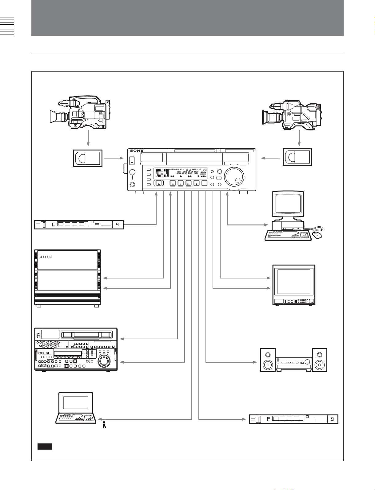
1-3 Sample System Configuration
Example for the J-10/10SDI
Betacam SX camcorder
Digital cassette
Reference video signal generator
J-10/10SDI
EXT SYNC
Betacam SP camcorder
Analog cassette
JZ-1
RS-232C
Computer
SDI (J-10SDI)
RS-422A
Server
a)
SDI (J-10SDI)
a)
S video/analog composite/
VTR
DV
Computer
a)
Note
Editing through this unit is not recommended.
analog component (J-10)
SDI (J-10SDI)
S video/analog composite/
analog component (J-10)
Analog audio
TC OUTPUT
(J-10SDI)
Video monitor
Audio monitor
Time code reader
1-4 Chapter 1 Overview
Page 11
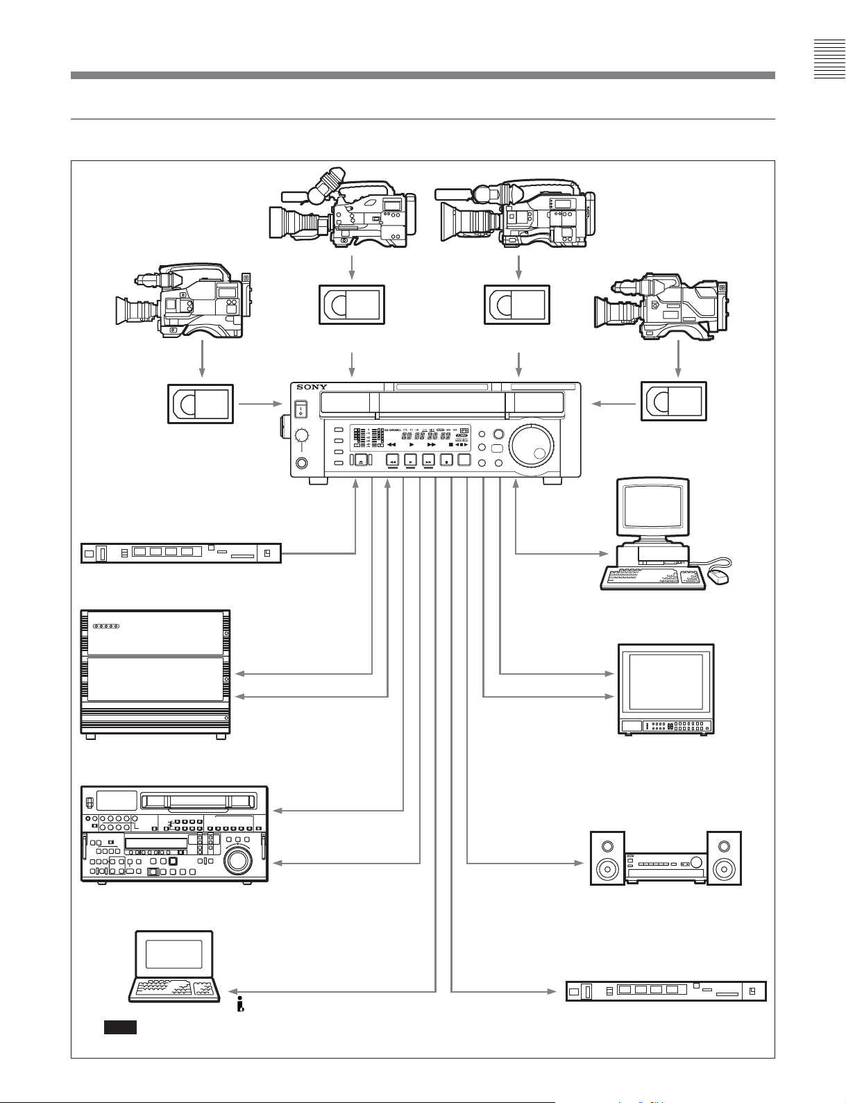
Example for the J-30/30SDI
MPEG IMX camcorder Digital Betacam camcorder
Chapter 1 Overview
Betacam SX camcorder
Digital cassette
Reference video signal generator
MPEG IMX cassette
J-30/30SDI
EXT SYNC
Betacam SP camcorder
Digital Betacam
cassette
Analog cassette
JZ-1
RS-232C
Computer
SDI (J-30SDI)
RS-422A
Server
a)
a)
VTR
Computer
a)
Note
Editing through this unit is not recommended.
DV
SDI (J-30SDI)
S video/analog composite/
analog component (J-30)
SDI (J-30SDI)
S video/analog composite/
analog component (J-30)
Analog audio
TC OUTPUT
(J-30SDI)
Video monitor
Audio monitor
Time code reader
Chapter 1 Overview 1-5
Page 12
Location and Function
of Parts
2-1 Control Panel
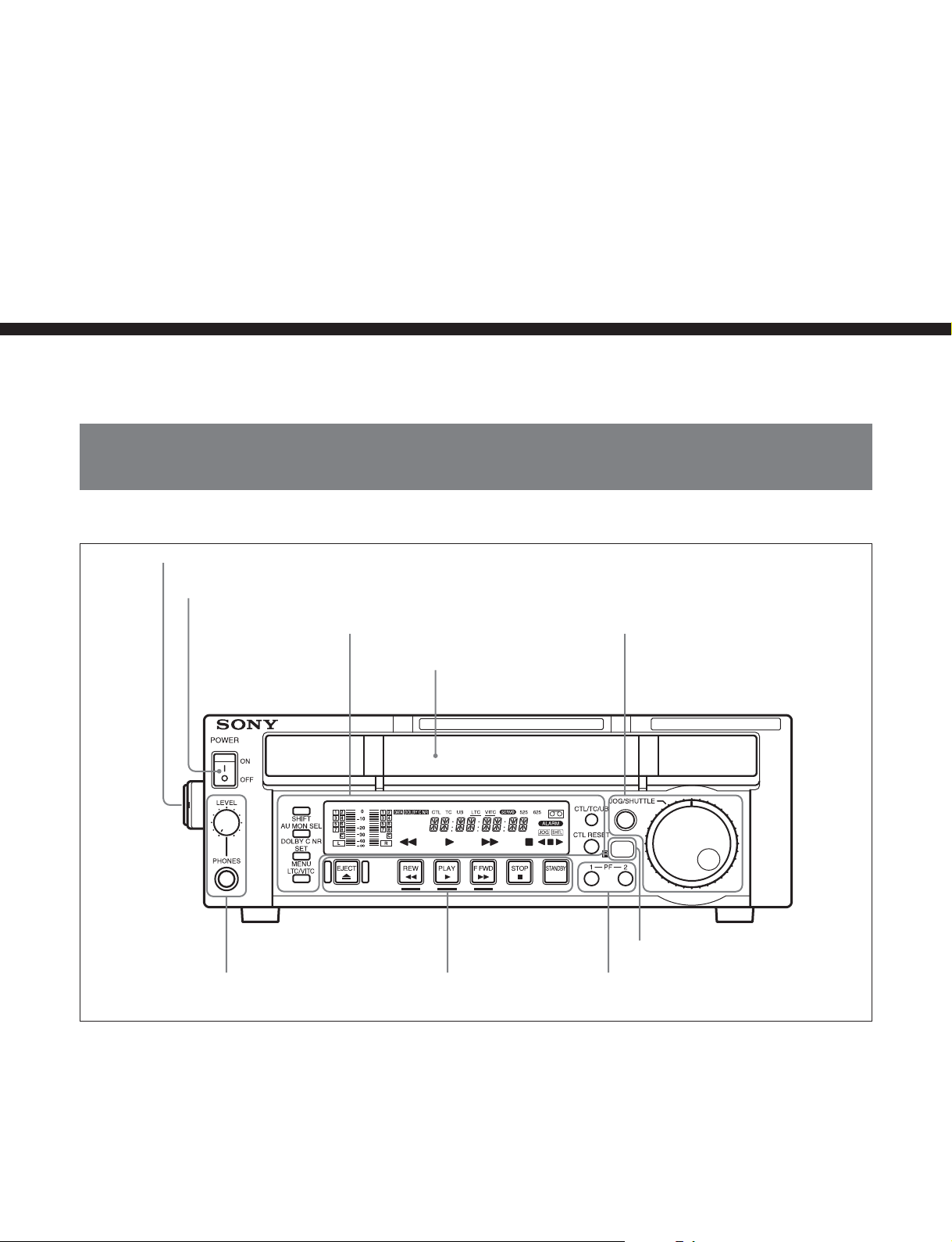
1 Carrying handle
Chapter 2
Chapter 2 Location and Function of Parts
2 POWER switch
6 PHONES jack and
control knob
Display section
(See page 2-2)
3 Cassette compartment
Tape transport control
section (See page 2-7)
Search control section
(See page 2-6)
4 Remote control detector
5 PF-1/2 buttons
1 Carrying handle
Use this handle to carry the unit or to stand the unit
vertically.
2 POWER switch
Press the side of the POWER switch marked “ON” to
turn the unit on. The fluorescent display and indicators
in the display section light.
Press the side of the POWER switch marked “OFF” to
turn the unit off.
Chapter 2 Location and Function of Parts 2-1
Page 13
2-1 Control Panel
3 Cassette compartment
Insert an S or L cassette.
Chapter 2 Location and Function of Parts
4 Remote control detector
Receives the infrared signal from the supplied Remote
Commander.
For details on the Remote Commander, see section 4-3
“Using the Remote Commander” on page 4-6.
5 PF (programmable function)-1/2 buttons
When using the Betacam SX or MPEG IMX format
and settting this unit into noiseless mode, use these
buttons to perform frame step playback (see page 4-3).
To the PF-2 button, you can assign functions that are
set in basic menu item 022, PF2 KEYSELECT.
Function “tape remain time” is assigned to the PF-2
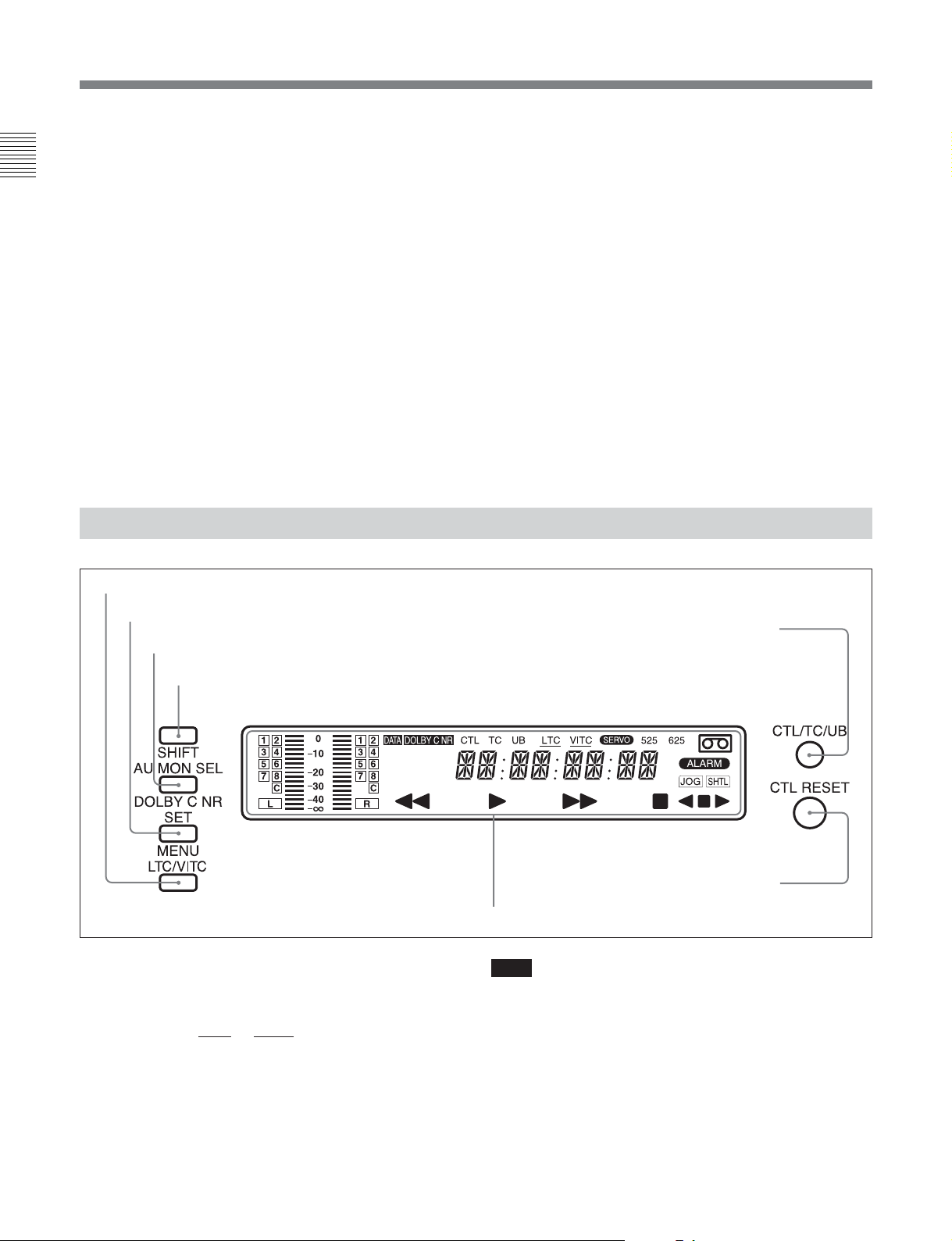
2-1-1 Display Section
1 LTC/VITC button
button as the factory default settings. While you are
pressing the button, the remaining tape time are
displayed in the display section.
For details on function assignment, see the section “Menu
bank operations (basic menu items B01 to B12) “ on page
7-5.
6 PHONES (headphones) jack and control knob
Connect stereo headphones with an impedance of
8 ohms to monitor the sound during playback.
The control knob adjusts the volume.
It is possible to make a setting so that the output
volume from the AUDIO MONITOR connectors is
controlled simultaneously.
Set AUDIO MONITOR OUTPUT LEVEL, extended
menu item 114, to VAR to enable the above feature.
2 SET/MENU button
3 AU MON SEL/DOLBY C NR button
4 SHIFT button
1 LTC/VITC button
This selects the time code displayed in the FL display
in the following sequence: LTC
underline for the
LTC or VITC time code setting
1)
, VITC2). The
indicators lights corresponding to the selection.
5 CTL/TC/UB button
6 CTL RESET button
7 FL (Fluorescent) display and indicators
Note
In this unit, VITC may not be displayed correctly
except during normal playback.
..........................................................................................................................................................................................................
1) LTC: abbreviation of Longitudinal Time code. This
time code is recorded on a longitudinal track on the tape.
Reading is unreliable at low speeds, and not possible at
all during still playback.
2) VITC: abbreviation of Vertical Interval Time code.
This time code is inserted in the vertical blanking
interval and recorded on the video tracks.
2-2 Chapter 2 Location and Function of Parts
Page 14
2 SET/MENU button
Use this button for setup menu operations and settings.
Press the SET/MENU button while holding down the
SHIFT button to display the contents of the setup
menu items on the FL display. When the setting is
finished, press only the SET/MENU button to fix the
settings and return to the normal display.
For details of setup menu settings and operations, see
Chapter 7.
3 AU MON SEL (audio monitor output select)/
DOLBY C NR
1)
(noise reduction) button
Press this button to function the AU MON SEL button.
Each press of this button switches the audio channel as
listed below. The selected channels are displayed in
the display section.
For the Betacam/Betacam SP format
Output modea)STEREO MONO
Audio channel L R L R
Press once CH-1 CH-2 CH-1 CH-1
Press twice CH-1,2 CH-1,2 CH-2 CH-2
Press 3 times CH-1,2 CH-1,2
Press 4 times
Each press of this
button switches the
mode as in the
above sequence.
Each press of this
button switches the
mode as in the
above sequence.
a) Set in basic menu item 026 of the setup menu
For the Betacam SX format
Output modea)STEREO MONO
Audio channel L R L R
Press once CH-1 CH-2 CH-1 CH-1
Press twice CH-3 CH-4 CH-2 CH-2
Press 3 times CH-1,2 CH-1,2 CH-3 CH-3
Press 4 times CH-3,4 CH-3,4 CH-4 CH-4
Press 5 times CH-1,2 CH-1,2
Press 6 times CH-3,4 CH-3,4
Press 7 times
a) Set in basic menu item 026 of the setup menu
Each press of this
button switches the
mode as in the
above sequence.
Each press of this
button switches the
mode as in the
above sequence.
For the MPEG IMX format (J-30/30SDI)
Output modea)STEREO MONO
Audio channel L R L R
Press once CH-1 CH-2 CH-1 CH-1
Press twice CH-3 CH-4 CH-2 CH-2
Press 3 times CH-5 CH-6 CH-3 CH-3
Press 4 times CH-7 CH-8 CH-4 CH-4
Press 5 times CH-1,2 CH-1,2 CH-5 CH-5
Press 6 times CH-3,4 CH-3,4 CH-6 CH-6
Press 7 times CH-5,6 CH-5,6 CH-7 CH-7
Press 8 times CH-7,8 CH-7,8 CH-8 CH-8
Press 9 times CH-1,2 CH-1,2
Press 10 times CH-3,4 CH-3,4
Press 11 times CH-5,6 CH-5,6
Press 12 times CH-7,8 CH-7,8
Press 13 times Each press of this
Each press of this
button switches the
mode as in the
above sequence.
button switches the
mode as in the
above sequence.
a) Set in basic menu item 026 of the setup menu
For the Digital Betacam format (J-30/30SDI)
Output modea)STEREO MONO
Audio channel L R L R
Press once CH-1 CH-2 CH-1 CH-1
Press twice CH-3 CH-4 CH-2 CH-2
Press 3 times CH-1,2 CH-1,2 CH-3 CH-3
Press 4 times CH-3,4 CH-3,4 CH-4 CH-4
Press 5 times CUE CUE CUE CUE
Press 6 times CH-1,2 CH-1,2
Press 7 times CH-3,4 CH-3,4
Press 8 times Each press of this
Each press of this
button switches the
mode as in the
above sequence.
button switches the
mode as in the
above sequence.
a) Set in basic menu item 026 of the setup menu
The latest setting for each format is saved in the
memory regardless of whether the power has been
turned on/off. Therefore, when you play any cassette
next time, it will be played back in the format last
saved. If there is no cassette in the unit, you can
change the audio channel in the format used the last
time you ejected the cassette.
Chapter 2 Location and Function of Parts
..........................................................................................................................................................................................................
1) DOLBY C NR: Dolby C noise reduction manufactured
under license from Dolby Laboratories Licensing
Corporation. “DOLBY” and the double-D symbol
are trademarks of Dolby Laboratories Licensing
Corporation.
Chapter 2 Location and Function of Parts 2-3
Page 15

2-1 Control Panel
Press this button while holding down the SHIFT
button to function the DOLBY C NR button. The
Chapter 2 Location and Function of Parts
DOLBY C NR indicator lights in the display section.
When you are using an oxide tape, it switches the
Dolby NR C-type system for analog audio on or off.
When you are using a metal tape, the Dolby C NR
system is automatically switched on, regardless of the
setting of this switch.
ON: Enables the Dolby C NR system for playback of
an analog Betacam oxide tape.
OFF: Disables the Dolby C NR system for playback
of an analog Betacam oxide tape.
The factory default setting is OFF.
4 SHIFT button
Hold down this button and press the AU MON SEL/
DOLBY C NR button to enable the DOLBY C NR
function. To enable the menu function, press the SET/
MENU button while holding down the SHIFT button.
Press the F FWD or REW button while holding down
the SHIFT button to do the forward or reverse cue-up
of the shot marks
and after of the current tape position. In addition, press
the PLAY button while holding down the SHIFT
button to superimpose the shot data2) (when using the
Betacam/Betacam SP/Betacam SX format) or UMID
(when using the Digital Betacam/ MPEG IMX format)
over the playback image. To clear the shot data or
UMID, again press the PLAY button while holding
down the SHIFT button.
1)
. These marks are located before
5 CTL/TC/UB (display switching) button
This selects the time data displayed in the fluorescent
display in the following sequence: CTL, TC, UB. As
the display changes, the corresponding indicators over
the fluorescent display also light/go off.
Time data display selection and display contents
Display
selection
CTL Tape running time (hours,
TC Playback time code read by
UB User bit value inserted in the
Value displayed Indicator status
CTL indicator
minutes, seconds, frames)
computed from the CTL
(control) signal recorded on
the tape during playback.
the internal time code
a)
reader.
playback time code.
a)
lights.
The TC indicator
lights.
The UB indicator
lights.
a) The LTC/VITC button switches between LTC and VITC.
6 CTL RESET button
Press this button to reset a CTL value displayed in the
FL display area.
7 FL (Fluorescent) display and indicators
These comprise a time data display, an audio monitor
display and of indicators. (See the figure on next page.)
For details on UMID, see Chapter 5.
..........................................................................................................................................................................................................
1) Shot marks
If you use a camcorder which allows you to use shot
marks, you can insert REC START marks or shot marks
in the user bits area in advance for easy editing.
This is called inserting shot marks.
2) Shot data
The information recorded continuously during the
process of shooting is called shot data.
The contents of the display vary corresponding to the
change of shooting conditions (e.g. changing
camcorders, shooting on different dates, etc.). If there
are any parts that contain no shot data by changing a
Model name
Date
Cassette
number
MODEL NAME DNW 0090
SERIAL NUMBER 010001
DATE 2001.05.11
TIME 12.55.10
CASSETTE NUMBER 0095
SHOT NUMBER 0052
ID1 AAAAAAAAAAAA
ID2 BBBBBBBBBBBB
ID3 CCCCCCCCCCCC
ID4 DDDDDDDDDDDD
TCR 23:59:59:29
Serial number
Time
Shot number
Camera ID
Time code
at recording
shooting camcorder, the unit displays blank data.
2-4 Chapter 2 Location and Function of Parts
Page 16
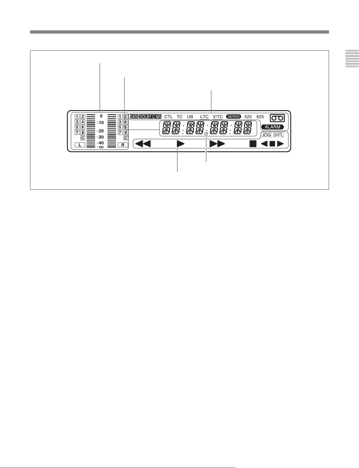
Audio monitor display area
Time data display area
Tape transport indicator area
Audio monitor display area
•L/R audio level meter
Indicates the audio levels of the 2 optionally selected
channels making up L/R (Left/Right).
•L/R audio channel display
Indicates the optionally selected channel numbers.
Time data display area
Normally this displays a CTL count, time code value,
or user bit value according to the selection of the CTL/
TC/UB button or LTC/VITC button. When a cassette
recorded in the DF mode is played back, the dot by the
❉ mark in the illustration above lights. At this time, the
two dots (:) located above the dot disappear.
It is also used to display error messages and the setup
menus.
For details of the display of the CTL count, time code value,
or user bit value, see the explanation given in “5 CTL/TC/
UB button” on page 2-4.
Indicator area
This includes the following indicators.
•DOLBY C NR (Dolby C noise reduction)
indicator: This lights when the Dolby noise
reduction circuit is functioning..
•CTL (control) indicator: This lights when a tape
running time (hours, minutes, seconds, frames)
computed from the CTL signal is displayed in the
time data display area.
•TC (time code) indicator: This lights when a time
code is displayed in the time data display area.
Chapter 2 Location and Function of Parts
Indicator area
❉
•UB (user bits) indicator: This lights when a user bit
value is displayed in the time data display area.
• LTC, VITC indicators: Regardless of the display in
the time data display area, these indicators light when
the corresponding time code values are being read.
When LTC has been selected using the LTC/VITC
button, the LTC indicator is displayed and
underlined. On the other hand, when VITC is
selected, the VITC indicator is displayed and
underlined.
• SERVO indicator: This lights when the servo lock
is functioning.
• ALARM indicator: This lights when a hardware
error is detected on the unit, and goes off when the
error is resolved. When this indicator is lit, an error
message appears in the time data display area.
• Cassette-in indicator q: This lights when a
cassette is loaded in the unit.
• DATA indicator: This lights when a tape, containing
audio data such as Dolby-E and AC-3 on its
DIGITAL AUDIO track, is played back.
•525, 625 (scan lines for the television standard)
indicators: Either of these indicators lights to show
the system for which this unit is set in basic menu
item 013 (NTSC: 525 scan lines, field frequency 60
Hz; PAL: 625 scan lines, field frequency 50 Hz).
Chapter 2 Location and Function of Parts 2-5
Page 17
2-1 Control Panel
Tape transport indicator area
• Tape transport indicator
Chapter 2 Location and Function of Parts
When you press each button in the tape transport
control section, the corresponding indicators light.
m: REW (rewind) indicator
B: PLAY indicator
When AUTO TRACKING (the automatic tape
loading function) is in operation, this indicator
flashes.
M: F FWD (fast forward) indicator
x: STOP indicator
• JOG/SHTL (jog/shuttle) indicator
The “JOG” indicator lights when playback is carried
out in jog mode, and the “SHTL” indicator lights
when playback is carried out in shuttle mode.
• JOG/SHTL (jog/shuttle) transport indicator
b: Jog/shuttle reverse indicator (green)
B: Jog/shuttle forward indicator (green)
x: Jog/shuttle still indicator (red)
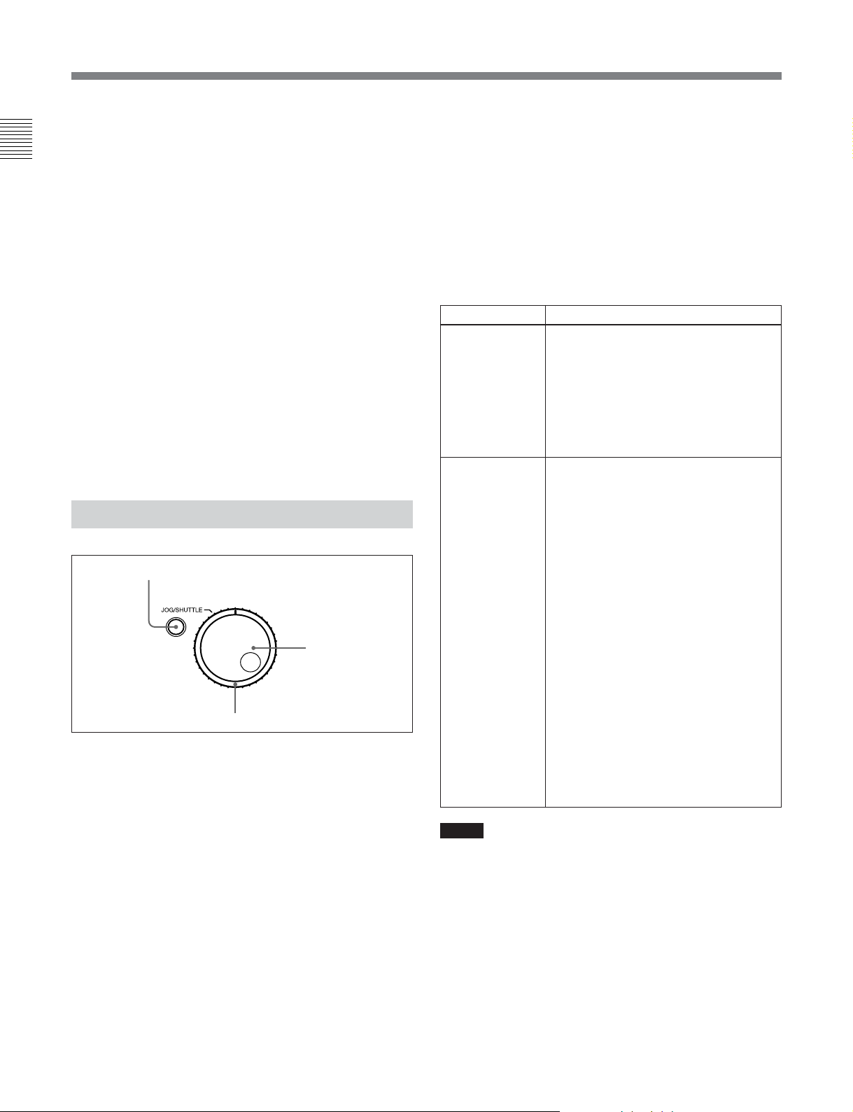
2-1-2 Search Control Section
1 JOG/SHUTTLE button
1 JOG/SHUTTLE button
Use this button to toggle between jog mode and shuttle
mode when using the JOG dial or SHUTTLE dial.
Press this button once for playback in jog mode, or
press this button twice for playback in shuttle mode
during playback or F FWD/REW. The corresponding
“JOG” indicator or “SHTL” indicator lights in the
display section.
2 JOG dial
Turn this to carry out playback in the modes shown in
the table in the right column. Turn the dial clockwise
for forward playback and counterclockwise for reverse
playback.
2 JOG dial
3 SHUTTLE dial
3 SHUTTLE dial
Turn this to carry out playback in the modes shown in
the following table. Turn the dial clockwise for
forward playback and counterclockwise for reverse
playback.
After pressing the JOG/SHUTTLE button, turn the
JOG dial for playback in jog mode and the SHUTTLE
dial for playback in shuttle mode.
Playback modes using the JOG/SHUTTLE dial
Playback mode Operations and functions
Jog Press the JOG/SHUTTLE button once to
light “JOG,” then turn the JOG dial, or
simply turn the JOG dial without lighting
“JOG.” Playback is carried out at a
speed corresponding to the rotating
speed of the JOG dial. The playback
speed range is from –1 to +1 times
normal speed.
The JOG dial has no detents.
Shuttle Press the JOG/SHUTTLE button twice to
light “SHTL,” then turn the SHUTTLE
dial, or simply turn the SHUTTLE dial
without lighting “SHTL.” Playback is
carried out at a speed corresponding to
the angular position of the SHUTTLE
dial. The playback speed range is as
follows.
When using a Digital Betacam tape
(J-30/30SDI): –21 to +21 times normal
speed
When using an MPEG IMX tape (J-30/
30SDI): –32/–38 to +32/+38 times
normal speed (NTSC/PAL)
When using a Betacam SX tape: –35
to +35 times normal speed
When using an analog Betacam tape:
–18/–20 to +18/+20 times normal
speed (NTSC/PAL)
The SHUTTLE dial has detents at the
center position, and at that point a still
picture is displayed.
Notes
•Normally, you turn the SHUTTLE dial after setting
the jog/shuttle mode by pressing the JOG/SHUTTLE
button. However, you can also set the jog/shuttle
mode simply by turning the dial. (This feature is
available when SELECTION FOR JOG/SHUTTLE
DIAL ENABLE, extended menu item 101 of the
setup menu, is set to DIAL.) In this case, you must
reset the SHUTTLE dial to the center position after
turning it, otherwise the dial may be moved by
vibration and the tape may start running in the shuttle
mode during playback.
2-6 Chapter 2 Location and Function of Parts
Page 18
•If the unit carries out reverse playback in the shuttle
mode at –0.5 times or less normal speed for 20
consecutive minutes, the reel motor heat protection
circuit automatically functions and the unit enters still
mode.
4 F FWD (fast forward) button
To start fast forwarding the tape, press this button. The
F FWD indicator in the display section lights. When
you are using a tape containing shot marks, press this
button while holding down the SHIFT button to cue-up
a shot mark position in the forward direction.
Chapter 2 Location and Function of Parts
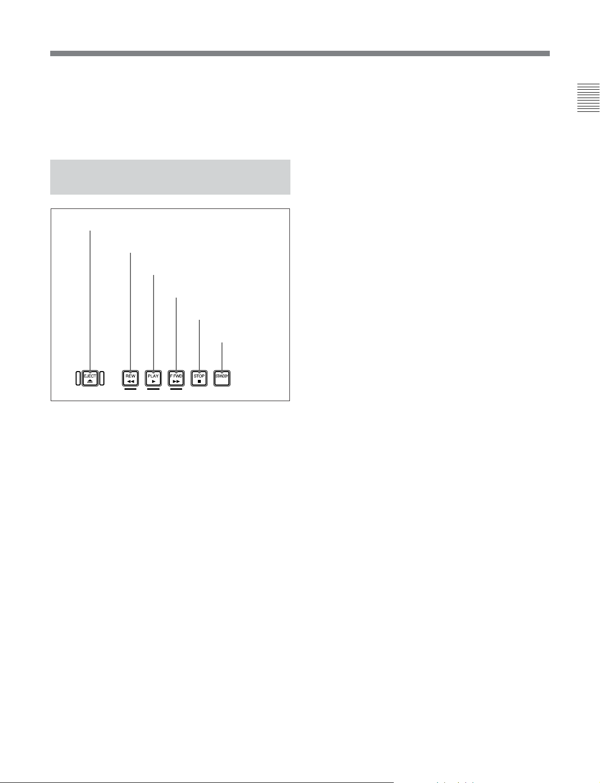
2-1-3 T ape T ransport Control Section
1 EJECT button
2 REW button
3 PLAY button
4 F FWD button
5 STOP button
6 STANDBY
1 EJECT button
Press this button to eject the cassette.
on/off button
5 STOP button
To stop playback, press this button. The STOP
indicator in the display section lights.
If REFERENCE SYSTEM ALARM, extended menu
item 105 of the setup menu, has been set to ON, this
button flashes when the external reference video signal
is not supplied.
6 STANDBY on/off button
When a cassette is inserted in the unit and the unit is in
the Stop mode, you can toggle the VTR standby mode
on and off by pressing this button.
In standby mode, the drum rotates and the tape sticks
to the drum. As a result, playback starts immediately.
If the unit is set to 8 minutes elapse (this value can be
varied using STILL TIMER extended menu item 501
of the setup menu) in standby mode, it automatically
switches out of standby mode to protect the tape.
2 REW (rewind) button
To rewind the tape, press this button. The REW
indicator in the display section lights. When you are
using a tape containing shot marks, press this button
while holding down the SHIFT button to cue-up a shot
mark position in the reverse direction.
3 PLAY button
To start playback, press this button. The PLAY
indicator in the display section lights.
When you are using a Betacam/Betacam SP/Betacam
SX tape containing shot data, press this button while
holding the SHIFT button to display shot data (see
page 2-4).
When you are using a Digital Betacam/MPEG IMX
tape containing UMID, press this button while holding
the SHIFT button to display UMID (see page
5-2).
To clear the shot data or UMID, again press this button
while holding down the SHIFT button.
Chapter 2 Location and Function of Parts 2-7
Page 19

2-2 Connector Panel
2-2-1 Connector Panel of the J-10/30
Chapter 2 Location and Function of Parts
6 AUDIO MONITOR
OUTPUT connectors
5 VIDEO OUTPUT
connectors
1 AC IN connector
2 RS232C connector
3 REMOTE IN (9P) connector
4 EXT SYNC input connector
1 AC IN connector
Connects to an AC outlet using the power cord (not
supplied).
2 RS232C (RS-232C serial interface) connector
(D-sub 9-pin)
Used to send or receive RS-232C remote control
signals and VTR status signals to/from an external
device such as a computer with the JZ-1 installed.
3 REMOTE IN (9P) connector (RS-422A serial
interface, 9-pin)
Controls the unit remotely from an external device
equipped with the Sony 9-pin remote control function.
4 EXT SYNC (external synchronization) input
connector
Inputs the reference video signal. However, on this
unit, use this for frame synchronization only, not for
color subcarrier synchronization.
5 VIDEO OUTPUT connectors
COMPOSITE (analog composite video) (SUPER)
output connector (phono jack): Outputs an analog
composite video signal. When basic menu item
005, DISPLAY INFORMATION SELECT, of the
setup menu is set as anything other than OFF, the
output from this connector outputs superimposed
character information such as time code, menu
settings, or alarm messages.
COMPOSITE (analog composite video) (SUPER)
output connector (BNC): Outputs an analog
composite video signal. When basic menu item
005, DISPLAY INFORMATION SELECT, of the
setup menu is set as anything other than OFF, the
output from this connector outputs superimposed
character information such as time code, menu
settings, or alarm messages.
S VIDEO output connector (Mini-DIN 4-pin):
Outputs an S VIDEO signal.
2-8 Chapter 2 Location and Function of Parts
Page 20

DV (i.LINK DV) output connector (IEEE1394,
6-pin):
Outputs video/audio signals in DV format
(IEEE1394, 6-pin).
When basic menu item 030, i.LINK
CHARACTER, of the setup menu is set to ON
and basic menu item 005, DISPLAY
INFORMATION SELECT is set as anything other
than OFF, the output from this connector outputs
superimposed character information such as time
code, menu settings, or alarm messages.
Notes
•Through the DV connector, only one DV
device can be connected to this unit. If you
intend to connect multiple DV devices, refer to
the manuals of them.
•The i.LINK (DV) output of this unit is used to
provide materials to a computer on which nonlinear editing software is installed. You can use
a Sony VTR equiped with an i.LINK (DV)
connector (DVCAM series of VTRs for
example) with this unit, though, the auto
dubbing function and editing function will not
be available.
•If the unit is connected to a device equipped
with a 6-pin DV jack, when you intend to
disconnect or reconnect the DV cable, turn off
the device and pull out the plug of its power
cord from the AC outlet beforehand. If you
connect or disconnect the DV cable while the
device is connected to the AC outlet, highvoltage current (8 to 40 V) is output from the
DV jack of the device to this unit, which may
cause a malfunction.
•When connecting a device that has a 6-pin DV
jack to this unit, first connect the plug of the
cable to the 6-pin DV jack of the device.
Chapter 2 Location and Function of Parts
COMPONENT (Y/R–Y/B–Y) output connectors
(BNC): Output analog component video signals (Y/
R–Y/B–Y).
6 AUDIO MONITOR OUTPUT connectors
Audio monitor (L/R) output connectors (XLR
3-pin, male): Output two (L and R) audio monitor
signals according to the setting of the AU MON
SEL/BOLBY C NR button on the control panel.
Audio monitor (L/R) output connectors (Phono
jack): Output two (L and R) audio monitor signals
according to the setting of the AU MON SEL/
DOLBY C NR button on the control panel.
Chapter 2 Location and Function of Parts 2-9
Page 21

2-2 Connector Panel
2-2-2 Connector Panel of the J-10SDI/30SDI
Chapter 2 Location and Function of Parts
7 AUDIO MONITOR
OUTPUT connectors
6 VIDEO OUTPUT
connectors
1 AC IN connector
2 RS232C connector
3 REMOTE IN (9P) connector
4 EXT SYNC input connector
5 TC OUTPUT connector
1 AC IN connector
Connects to an AC outlet using the power cord (not
supplied).
2 RS232C (RS-232C serial interface) connector
(D-sub 9-pin)
Used to send or receive RS-232C remote control
signals and VTR status signals to/from an external
device such as a computer with the JZ-1 installed.
3 REMOTE IN (9P) connector (RS-422A serial
interface, 9-pin)
Controls the unit remotely from an external device
equipped with the Sony 9-pin remote control function.
4 EXT SYNC (external synchronization) input
connector
Inputs the reference video signal. However, on this
unit, use this for frame synchronization only, not for
color subcarrier synchronization.
5 TC OUTPUT (time code output) connector
(BNC)
Outputs the playback time code.
6 VIDEO OUTPUT connectors
COMPOSITE (analog composite video) (SUPER)
output connector (phono jack): Outputs an analog
composite video signal. When the basic menu
item 005, DISPLAY INFORMATION SELECT,
of the setup menu is set as anything other than
OFF, the output from this connector outputs
superimposed character information such as time
code, menu settings, or alarm messages.
COMPOSITE (analog composite video) (SUPER)
output connector (BNC): Outputs an analog
composite video signal. When the basic menu
item 005, DISPLAY INFORMATION SELECT,
of the setup menu is set as anything other than
OFF, the output from this connector outputs
superimposed character information such as time
code, menu settings, or alarm messages.
S VIDEO output connector (Mini-DIN 4-pin):
Outputs an S VIDEO signal.
2-10 Chapter 2 Location and Function of Parts
Page 22

DV (i.LINK DV) output connector (IEEE1394,
6-pin):
Outputs video/audio signals in DV format.
When basic menu item 030, i.LINK
CHARACTER, of the setup menu is set to ON
and basic menu item 005, DISPLAY
INFORMATION SELECT is set as anything other
than OFF, the output from this connector outputs
superimposed character information such as time
code, menu settings, or alarm messages.
Notes
•Through the DV connector, only one DV
device can be connected to this unit. If you
intend to connect multiple DV devices, refer to
the manuals of them.
•The i.LINK (DV) output of this unit is used to
provide materials to a computer on which nonlinear editing software is installed. You can use
a Sony VTR equiped with an i.LINK (DV)
connector (DVCAM series of VTRs for
example) with this unit, though, the auto
dubbing function and editing function will not
be available.
•If the unit is connected to a device equipped
with a 6-pin DV jack, when you intend to
disconnect or reconnect the DV cable, turn off
the device and pull out the plug of its power
cord from the AC outlet beforehand. If you
connect or disconnect the DV cable while the
device is connected to the AC outlet, highvoltage current (8 to 40 V) is output from the
DV jack of the device to this unit, which may
cause a malfunction.
•When connecting a device that has a 6-pin DV
jack to this unit, first connect the plug of the
cable to the 6-pin DV jack of the device.
7 AUDIO MONITOR OUTPUT connectors
Audio monitor (L/R) output connectors (XLR
3-pin, male): Output two (L and R) audio monitor
signals according to the setting of the AU MON
SEL/DOLBY C NR button on the control panel.
Audio monitor (L/R) output connectors (Phono
jack): Output two (L and R) audio monitor signals
according to the setting of the AU MON SEL/
DOLBY C NR button on the control panel.
Chapter 2 Location and Function of Parts
SDI (serial digital interface) output connector:
Outputs a video/audio signal in D1 format without
superimposed character information.
SDI (serial digital interface) (SUPER) output
connector: Outputs a video/audio signal in D1
format. When basic menu item 005, DISPLAY
INFORMATION SELECT, of the setup menu is
set as anything other than OFF, the connector
outputs the superimposed character information
such as time code, menu settings, or alarm
messages.
Chapter 2 Location and Function of Parts 2-11
Page 23

Chapter 3
Preparations
3-1 Installation
You can install this unit horizontally as well as
vertically. However, it is necessary to use the supplied
vertical installation stands to prepare the unit for
vertical installation as shown in the figure.
Notes
•When you install this unit vertically, be sure that the
handle faces up.
•Regardless of whether you install the unit
horizontally or vertically, make sure there is a space
of 5 cm (2 inches) or more around the unit.
Chapter 3 Preparations
Vertical
installation
stands
Chapter 3 Preparations 3-1
Page 24

3-2 Cassettes
Cassette types
This unit uses the following 1/2-inch tape width
cassettes:
•Digital Betacam cassette (J-30/30SDI only)
•MPEG IMX cassette (J-30/30SDI only)
Chapter 3 Preparations
•Betacam SX cassette
•Betacam SP cassette
•Betacam cassette
•UVW cassette
Inserting and ejecting cassettes
Insert or eject a cassette while the unit is powered on.
Inserting a cassette
EJECT button
Removing slack from the tape
Press one of the reels in with a finger, and turn gently
in the direction shown by the arrows until there is no
slack in the tape.
Ejecting a cassette
Press the EJECT button.
The cassette is ejected.
If the tape slacks inside the unit, pressing the EJECT button
may not eject the cassette. For information about how to
remove the cassette in such a case, refer to the Maintenance
Manual.
S cassette
1
L cassette
1 Turn the POWER switch on.
2 Check the following points before inserting the
cassette with the orientation shown in the figure.
•Check that there is no slack in the tape.
•Check that the message “E10-0000” is not shown
in the time data display area.
The cassette is drawn into the unit.
If the message “E10-0000” appears in the time data
display area, there is moisture condensation in the unit.
For steps to take when “E10-0000” is displayed, see
section 8-3 “Moisture Condensation” on page
8-2.
3-2 Chapter 3 Preparations
Page 25

Playback
4-1 Playback Procedures
Chapter 4
Chapter 4 Playback
4-1-1 Normal Playback
SHIFT button
AU MON SEL/
DOLBY C NR button
Insert a cassette beforehand.
For details of how to insert a cassette, see the section
“Inserting and ejecting cassettes” on page 3-2.
To start playback
Press the PLAY button.
Cassette compartment
STOP button
PLAY button
If you play back to the end of the tape
The tape is automatically rewound, and stops.
(When AUTO REWIND, extended menu item 125, is
set to ENA)
Notes
•If you playback a Betacam/Betacam SP cassette
immediately after playing back a Betacam SX
cassette or Digital Betacam cassette, it may take
several seconds for playback to start.
•This unit uses an auto-tracking function (when using
the Digital Betacam or MPEG IMX format). The
factory setting for the auto-tracking is on (AUTO
TRACKING ON). You can turn auto-tracking off.
For details on how to change the setting, contact your
nearest Sony dealer. While this unit is pulling the
tape in, the PLAY button indicator B flashes.
When using the Dolby C NR system
When using an analog Betacam cassette, you can use
Dolby C NR for audio playback.
To activate the Dolby NR system, press the AU MON
SEL/DOLBY C NR button while holding down the
SHIFT button on the control panel.
To stop playback
Press the STOP button.
Chapter 4 Playback 4-1
Page 26

4-1 Playback Procedures
Chapter 4 Playback
4-1-2 Playback in Jog Mode
1
1,2,3
In jog mode, the JOG dial controls the playback speed
based the speed at which the dial is turned. The
playback speed range is ±1 times normal speed.
Use the following procedure to carry out playback in
jog mode.
1 Turn the JOG dial directly or press the JOG/
SHUTTLE button to light the JOG indicator.
Pressing the JOG/SHUTTLE button toggles
between jog mode and shuttle mode.
2 Turn the JOG dial in the desired direction, at a
speed corresponding to the desired playback speed.
Playback in jog mode starts.
3 To stop playback in jog mode, stop turning the
JOG dial.
It is possible to make pressing the JOG/SHUTTLE
button to switching between JOG and SHUTTLE
mode.
Select “KEY” in SELECTION FOR JOG/
SHUTTLE DIAL ENABLE, extended menu item
101, to enable the above feature. (This is the
default setting.)
4-1-3 Playback in Shuttle Mode
1
1,2,33
In shuttle mode, the SHUTTLE dial controls the
playback speed based on the angular position of the
dial.
•When using a Digital Betacam tape: ±21 times
•When using an MPEG IMX tape: ±32 times/±38
times (NTSC/PAL)
•When using a Betacam SX tape: ±35 times
•When using an analog Betacam tape: ±18/±20 times
(NTSC/PAL)
+ indicates forward direction speed, – indicates reverse
direction speed.
The SHUTTLE dial has detents at the center position,
move the SHUTTLE dial to the center indent to
display a still picture.
Use the following procedure to carry out playback in
shuttle mode.
1 Turn the SHUTTLE dial directly or press the JOG/
SHUTTLE button twice to light the SHTL
indicator.
If the SHUTTLE dial points to a position other
than the center, playback in shuttle mode starts at a
speed corresponding to the angular position of the
dial.
4-2 Chapter 4 Playback
Pressing the JOG/SHUTTLE button toggles
between jog mode and shuttle mode.
Page 27

2 Turn the SHUTTLE dial to the angle
corresponding to the desired playback speed.
Playback in shuttle mode starts.
4-1-4 Noiseless Playback Function and Frame Step Playback Function
3 Return the SHUTTLE dial to the center indent
position or press the STOP button to cancel shuttle
mode playback.
It is possible to make pressing the JOG/SHUTTLE
button to switching between JOG and SHUTTLE
mode.
Select “KEY” in SELECTION FOR JOG/
SHUTTLE DIAL ENABLE, extended menu item
101, to enable the above feature. (This is the
default setting.)
To return to normal-speed playback
Press the PLAY button.
To alternate between normal-speed playback
and shuttle mode playback
Set the SHUTTLE dial to the position
corresponding to the desired shuttle playback
speed first. Press the PLAY button, and then press
the JOG/SHUTTLE button twice.
For intermittent shuttle mode playback, press the
STOP button first and then press the JOG/
SHUTTLE button twice.
Normally, you turn the SHUTTLE dial after setting
the jog/shuttle mode by pressing the JOG/
SHUTTLE button. You can also set the jog/shuttle
mode, however, by directly turning the dial. (This
is available when SELECTION FOR JOG/
SHUTTLE DIAL ENABLE, extended menu item
101, is set to DIAL.) In this case, you must reset
the SHUTTLE dial to the center position after
turning it, otherwise the dial is moved by vibration
and the tape may start running in the shuttle mode
during playback.
When you are using the Betacam SX or MPEG IMX
format, you can put this unit into noiseless mode for
noiseless jog and shuttle playback at up to ±0.5 times
normal speed. During noiseless playback, audio is
muted for the MPEG IMX format. For the Betacam
SX format, discontinuous audio in frame units is
heard. In noiseless mode, you can use the PF-1/2
buttons to step through frames. The step for the MPEG
IMX format is 1 frame. The step for the Betacam SX
format is 2 frames.
To select noiseless mode
In the setup menu, set basic menu item 025,
NOISELESS to Enable. (The factory default setting is
Disable.) JOG or SHTL flashes in the display section.
To perform noiseless playback
Put the unit into noiseless mode, press the JOG or
SHUTTLE button, and rotate the JOG/SHUTTLE dial.
This allows you to perform noiseless playback at up to
±0.5 times normal speed.
In noiseless mode, the emphasis is on slow-speeds.
Therefore the SHUTTLE dial speed settings change
from the Normal (0), ±0.03, ±0.12, ±0.5, ±1, ±2, ±10,
±35 (Betacam SX format) (15 steps) to 0, ±0.03,
±0.06, ±0.12, ±0.25, ±0.5, ±1, ±10 (15 steps). For the
MPEG IMX format, extended menu item 922 of the
setup menu IMX NOISELESS PB allows you to set
the playback picture to FRAME, FIELD 1, or FIELD 2
(the factory default setting is FRAME).
Chapter 4 Playback
Chapter 4 Playback 4-3
Page 28

4-1 Playback Procedures
To perform frame step playback
Put the unit into noiseless mode and press the PF-1 or
PF-2 button.
When you are using the Betacam SX format, each
press of the PF-1 button steps 2 frames back, and each
press of the PF-2 button steps 2 frames forward. When
you are using the MPEG IMX format, the buttons step
1 frame in the same directions.
Chapter 4 Playback
Notes
•To perform frame step playback, always press the
PLAY button once before pressing the PF-1 or PF-2
button. When you switch between FWD and REV,
the picture may not be updated until you press the
PF-1 or PF-2 button twice.
•During frame step playback, the picture and the LTC
may be up to 5 frames out of sync. We recommend
that you use VITC.
•Block noise may remain visible during frame step
playback. If this occurs, step in the reverse direction,
or press the PLAY button again.
4-4 Chapter 4 Playback
Page 29

4-2 Superimposed Character Information
Displayed items
1 Types of time data
Time data
2 Drop frame mark
of time data
3 VITC field mark
4 Operation mode
1 Types of time data
Display Meaning
CTL CTL counter data
TCR LTC reader time code
UBR LTC reader user bit
TCR. VITC reader time code
UBR. VITC reader user bit
Note
If the time data or user bit cannot be read correctly,
they will be displayed with an asterisk. For example,
“T*R”, “U*R”, “T*R.” or “U*R.”.
Chapter 4 Playback
When basic menu item 005 of the setup menu
DISPLAY INFORMATION SELECT is set as
anything other than OFF, the video signal output from
the COMPOSITE (SUPER) output connector, SDI
(SUPER) output connector (for J-10SDI/30SDI only)
or
DV connector contains superimposed character
information (overlaid display), including time code,
menu settings, or alarm messages.
For details on the settings for superimposed display, see
DISPLAY INFORMATION SELECT, basic menu item 005
on page 7-7, SDI OUT CHARACTER, basic menu item 027
on page 7-9, and i.LINK CHARACTER, basic menu item 030
on page 7-9.
Adjusting the character display
The basic menu adjusts the position, size and type of
the superimposed characters.
For details of the basic menu, see section 7-3 “Basic Menu”
on page 7-7.
Note
As the factory default setting, basic menu item 005,
DISPLAY INFORMATION SELECT is set to OFF.
Changing the setting of basic menu item 005,
DISPLAY INFORMATION SELECT allows different
time data to be displayed in the bottom line of the
display.
For details, see section 7-3 “Basic Menu” on page 7-7.
2 Drop frame mark of time data
“ . ”: Drop frame mode
“ : ”: Non-drop frame mode
3 VITC field mark
“ ” blank: When displaying Field 1 and 3
“ * ”: When displaying Field 2 and 4
4 Operation mode
The field is divided into two blocks, A and B.
•Block A: displays the operation mode.
•Block B: displays the servo lock status or tape speed.
AB
Display
Block A Block B
TAPE UNTHREAD Cassette is not loaded.
STANDBY OFF Standby off mode
STOP Stop mode
F.FWD Fast forward mode
REW Rewind mode
PLAY Playback mode (servo unlocked)
PLAY LOCK Playback mode (servo locked)
JOG STILL A still picture in jog mode
JOG FWD Jog mode in forward direction
JOG REV Jog mode in reverse direction
SHUTTLE STILL A still picture in shuttle mode
SHUTTLE (Speed) Shuttle mode
Operation mode
Chapter 4 Playback 4-5
Page 30

4-1 Playback Procedures
REMOTE INTERFACE
137
213:WIRELESS-off
501
❉
4-3 Using the Remote Commander
Chapter 4 Playback
Pull off the transparent film covering the battery parts.
4-3-1 How to Change the Lithium Battery
1 Pull out the lithium battery case.
Pull the battery case toward you while releasing
the lock by plucking it with your fingernail.
2 Set lithium battery in the case so that the + symbol
on the battery is facing you.
4-3-2 Setting Menu
When a Remote Commander is used, WIRELESS
REMOTE CONTROL, extended menu item 213, must
to be set to ON. (It is set to OFF at the factory.)
(The following operation is an example of how
WIRELESS REMOTE CONTROL is switched from
OFF to ON.)
1 Select WIRELESS REMOTE CONTROL,
extended menu item 213, to display it.
The illustration shows the information displayed in
the time data display area and on the monitor
connected to the COMPOSITE (SUPER) output
connector, SDI (SUPER) output connector (for J10SDI/30SDI only) or
Time data display area
Monitor screen
DV connector.
3 Push the lithium battery case back into its original
position.
Notes on the Remote Commander
•If there is an obstacle between the Remote
Commander and the remote control detector, the
Remote Commander sometimes does not work
properly. Point the Remote Commander at the remote
control detector on the front side of the unit.
•The effective remote control area is limited. It
becomes easier to control the unit the closer you get
and if you point the Remote Commander directly at
the front of the unit.
•Change the battery when the Remote Commander
4-6 Chapter 4 Playback
does not work properly.
Items without ❉ are omitted.
Page 31

2 Turn the JOG/SHUTTLE dial to change the setting
from “OFF” to “ON” while holding down the JOG/
SHUTTLE button, and then release the JOG/
SHUTTLE button.
Time data display area
Monitor screen
REMOTE INTERFACE
137
❉
213:WIRELESS-on
501
Items without ❉ are omitted.
(ON flashes while the JOG/SHUTTLE button is
being pressed.)
3 Press the SET/MENU button.
Time data display area and monitor go back to the
original views.
This unit
Remote control detector
Infrared transmitter
Chapter 4 Playback
Remote
Commander
Note
When two or more units of J-10/10SDI/30/30SDI or
J-H1/H3 (J-H series of compact players) are placed
close to each other, the Remote Commander may
affect more than one unit. In this case, select OFF in
WIRELESS REMOTE CONTROL, extended menu
item 213, of the other units you do not want to operate.
4-3-3 Operating the Remote Commander
Press the function keys while pointing the infrared
transmitter of the Remote Commander at the remote
control detector.
Each key functions same as the corresponding key on
the control panel attached to the unit.
Note
For the SEARCH key, is 10 times forward speed,
is 10 times reverse speed.
Chapter 4 Playback 4-7
Page 32

Chapter 4 Playback
4-4 Operation via Computer (With the JZ-1
4-1 Playback Procedures
Software)
The following operations will be available when using
the unit connected to a computer with the optional JZ1 software installed.
•Controlling basic operations such as play, fast
forward, rewind, stop, jog playback, and shuttle
playback via the computer
•Capturing images using shot mark data
For details on installation and software operation, refer to
the Readme file and the online help supplied with the JZ-1
software.
4-4-1 Capturing Images Using Shot Mark Data
If shot mark data has been recorded, you can
automatically read image and related data based on the
shot mark data. (You will need to install a video
capture card in your computer.)
An image that has been read will be displayed as a
thumbnail image. Double-clicking the thumbnail
image quickly finds the beginning of the segment.
Based on the thumbnail image position (cue point),
you can set an IN point and OUT point.
4-8 Chapter 4 Playback
Page 33

Chapter 5
UMID Functions
5-1 Overview of UMID Functions
The UMID (Unique Material Identifier) is a type of
meta-data in video and audio materials. It has been
internationally standardized in SMPTE Standard
330M. This unit supports generation of UMIDs
recorded in the Digital Betacam or MPEG IMX
format.
The UMID is made up of a section called the “Basic”
section and a section called the “Source Pack” section.
The Basic section contains information such as the
device that recorded the material and whether the
material is the original or a copy. The Source Pack
section contains information about when/where/who
recorded the material.
UMID Basic Instance Number
A UMID with a Basic section only is called a Basic
UMID. A UMID with both Basic and Source Pack
sections is called an Extended UMID. The following
figure shows a general overview of the information
contained in a UMID.
Chapter 5 UMID Functions
Copy or original
Material Number
Which device recorded the original
Source Pack Date/Time
When was it recorded
Spatial Co-ordinates
Where was it recorded
Stored Ownership
Who recorded it
Chapter 5 UMID Functions 5-1
Page 34

5-2 UMID Output and Display
This section explains how to output and display
UMIDs.
5-2-1 UMID Output Settings
You can choose to output UMIDs or not from the SDI
or SDI (SUPER) output connector, and select either
Basic UMID or Extended UMID when you choose to
output UMIDs. Make these settings using extended
menu item 651, UMID OUTPUT.
See page 7-11 for more information about extended menu
item 651.
5-2-2 UMID Display
Chapter 5 UMID Functions
During playback, UMID data appears on the video
monitor by superimposition.
To display the UMID
1 Instance Number Generation Method
2 Instance Number
3 Material Number Generation Method
4, 5 Material Number
6 Year/Month/Date
7 Hour:Minute:Second
8 Time Zone
9 GPS Altitude
0 Number of Satellites
qa Auxiliary Device
(“ ”: not equiped, “+”: equiped)
qs PDOP (Position Dilution Of Precision value)
qd Longitude (E: east/W: west)
qf Latitude (S: south/N: north)
qg Organization Code
qh User Code
qj Country Code
Press the PLAY button while holding down the SHIFT
button.
To exit from UMID display
Press again the PLAY button while holding sown the
SHIFT button.
UMID display on the video monitor
During playback in the Digital Betacam format
(J-30SDI) or in the MPEG IMX format (J-30/30SDI),
the video monitor connected to the COMPOSITE
(SUPER) output connector, SDI (SUPER) output
connector (for J-30SDI only) or
displays all UMID items at once as shown in the
following figure.
DV connector
5-2 Chapter 5 UMID Functions
Page 35

Chapter 6
Essence Marks
6-1 Overview of Essence Mark Functions
An essence mark uses a term value dictionary item as
defined in the SMPTE RP210A Metadata Dictionary
to express and transfer points such as recording start
points and edit point candidates in up to 32 bytes of
data.
The basic format of the SMPTE RP210A Metadata
Dictionary is defined in SMPTE 336M Data Encoding
Protocol using Key-Length-Value (KLV coding
specifications).
Chapter 6 Essence Marks
Chapter 6 Essence Marks 6-1
Page 36

5-2 Menu Operations
When playing back a tape, essence marks recorder on
the tape can be output to SDI signals. Information such
as shot marks recorded on the tape can also be
converted into essence marks and output.
Selecting whether to output essence
marks
You can select whether or not to output essence marks
when you play back a tape. Make this selection using
extended menu item 657, ESSENCE MARK TAPE
OUTPUT.
See page 7-11 for more information about extended menu
item 657.
Outputting shot marks converted into
essence marks
Chapter 6 Essence Marks
You can select whether or not to convert shot marks
recorded on a tape into essence marks for output when
you play back the tape. Make this selection using
extended menu item 658, SHOT MARK ESSENCE
MARK CONVERT.
When extended menu item 658 is set to ON, you can
specify the VANC
marks in extended menu item 660, ESSENCE MARK
VANC LINE.
6-2 Essence Mark Output
1)
line into which to insert essence
See page 7-11 for more information about extended menu
items 658 and 660.
..........................................................................................................................................................................................................
1) VANC: Vertical ancillary (data).
6-2 Chapter 6 Essence Marks
Page 37

Setup Menu
7-1 Menu System Configuration
Chapter 7
The principal setup operations required before
operating this unit can be carried out using setup
menus.
The menu system of this unit is comprised of a basic
menu and an extended menu.
•Basic menu
This menu is used to make the following settings:
– the digital hours meter
– the character information superimposed on the
output to the monitor
– settings for switching between the 525 (NTSC) and
625 (PAL) systems
– settings for the menu banks for retaining menu
settings
•Extended menu
This menu is used to make the following wide range
of settings on this unit:
– the control panel functions
– tape protection
– video and audio control
– digital data processing
This unit allows up to two menu settings to be stored
in menu banks 1 and 2.
The stored menu settings can be called up to use as
required.
For more information, see “Menu bank operation (basic
menu items B01 to B12)” on page 7-5.
Chapter 7 Setup Menu
Chapter 7 Setup Menu 7-1
Page 38

7-2 Menu Operations
7-2 Menu Operations
This section describes the basic menu displays and
how to change the settings.
For information about how to use basic menu item 013, see
“Switching between 525/625 line systems (basic menu item
013)” on page 7-4, and for information about how to
operate items B01 to B12, see “Menu bank operations
(basic menu items B01 to B12)” on page 7-5.
For information about how to use the extended menu, see
the section “Extended menu operations” on page 7-6.
Cursor indicating
the currently
selected item
*HO1:OPE HOURS - 102
HO2:DRUM HOURS - 52
-------
Chapter 7 Setup Menu
Displaying the menus
SHIFT button
Time data display area
SET/MENU button
Press the SET/MENU button while holding down the
SHIFT button.
The setting of the currently selected menu item
appears in the time data display area.
If the SET/MENU button is pressed while holding
down the SHIFT button to display the menu settings in
the time data display area, a full-screen version also
appears on a monitor connected to the COMPOSITE
(SUPER) output connector, SDI (SUPER) output
connector (J-10SDI/30SDI only), or
DV connector as
shown in the above figure.
Changing the currently displayed menu
item
JOG/SHUTTLE button
Item number
(flashing)
Item name (first four
characters)
Displaying the menus on the monitor
Menu setting can be done on the monitor while
superimposing is set to ON.
7-2 Chapter 7 Setup Menu
JOG/SHTL indicator
JOG/SHUTTLE dial
Turn the JOG/SHUTTLE dial.
Turning the JOG/SHUTTLE dial to the right
increments the item number and turning it to the left
decrements the item number.
The item number changes at a rate depending on the
JOG/SHUTTLE dial position (when the SHTL
indicator is lit) or on the JOG/SHUTTLE dial rotation
rate (when the JOG indicator is lit).
Page 39

Changing a menu item setting value
To change the setting value of the currently displayed
menu item, use the following procedure.
Resetting the menu settings to their
factory default values (basic menu item
B20)
Time data display area
2
1
1 Holding down the JOG/SHUTTLE button, turn the
JOG/SHUTTLE dial.
The setting value changes at a rate based on the
SHUTTLE dial position or on the JOG dial
rotation rate.
Setting value (flashes while changing)
2 When the desired setting value is displayed, press
the SET/MENU button.
This saves the new setting value, and the menu
display disappears from the time data display area.
SET/MENU button
1 Set RESET SETUP, basic menu item B20, to ON.
“PUSH SET” appears in the time data display area,
and “Push SET button” appears on the monitor
screen.
2 Press the SET/MENU button.
The current active menu settings (see “Menu bank
operations (basic menu items B01 to B12)”) are
reset to their factory default settings.
3 Press the SET/MENU button again.
The settings are saved and the menu display
disappears from the time data display area.
Chapter 7 Setup Menu
To cancel the change
Press the SET/MENU button while holding down
the SHIFT button before pressing the SET/MENU
button only.
The menu display disappears from the time data
display area without saving the new setting value.
Chapter 7 Setup Menu 7-3
Page 40

7-2 Menu Operations
Chapter 7 Setup Menu
Switching between 525/625 line systems
(basic menu item 013)
Using the following procedure, you can set basic menu
item 013, 525/625 SYSTEM SELECT, to ON, and
then switch between 525 (NTSC) and 625 (PAL).
(The following is the procedure example of switching
from a 525 (NTSC) system to a 625 (PAL) system.)
1 Select basic menu item 013 and display it.
The time data display area and the monitor screen
connected the COMPOSITE (SUPER) output
connector, SDI (SUPER) output connector (for
J-10SDI/30SDI only) or
following displays.
Time data display area
Monitor screen
525/625 SYSTEM
DV connector show the
ITEM-013
SELECT
2 Holding down the JOG/SHUTTLE button, turn the
JOG/SHUTTLE dial to change the setting from
OFF to ON.
The displays change as follows.
Time data display area
Monitor screen
ITEM-013
525/625 SYSTEM
SELECT
ON
Push SET button!!
3 Press the SET/MENU button.
The displays change as follows.
Time data display area
OFF
Monitor screen
525/625 SYSTEM SELECT
525
If the 525/625 setting
is changed, turn power
off and on!
7-4 Chapter 7 Setup Menu
Page 41

4 Holding down the JOG/SHUTTLE button, turn the
JOG/SHUTTLE dial to change the setting from
525 to 625.
The displays change as follows.
Time data display area
This switches from the 525 (NTSC) to the 625
(PAL) system; the 525 indicator goes off, and the
625 indicator lights.
The menu settings disappear from the time data
display area, and returns to the normal indications.
Menu bank operations (basic menu items
B01 to B12)
Monitor screen
525/625 SYSTEM SELECT
625
Push SET button!!
To cancel the 525/625 setting operation
Holding down the SHIFT button, press the SET/
MENU button the required number of times to exit
from the menu.
5 Press the SET/MENU button.
The displays change as follows.
Time data display area
You can see
“POWER OFF/ON”
by scrolling the
Monitor screen
525/625 SYSTEM SELECT
indication.
This unit allows two different complete sets of menu
settings to be saved in what are termed “menu banks,”
numbered 1 and 2. Saved sets of menu settings are
recalled for use as required.
To jump to menu item B01 or H01
The unit recalls any required menu items when you
turn the JOG/SHUTTLE dial after pressing the SET/
MENU button while holding down the SHIFT button.
Press the SET/MENU button while holding down the
SHIFT button, then press the CTL/TC/UB button.
Every time you press the CTL/TC/UB button, menu
item H01 or B01 is recalled alternately.
Saving the current active menu settings
Set menu item SAVE BANK 1, basic menu item B11,
or SAVE BANK 2, basic menu item B12, to ON,
depending on which of the menu banks you wish to
use to save the setting, then press the SET/MENU
button.
Recalling settings from a menu bank
Set menu item RECALL BANK 1, basic menu item
B01, or RECALL BANK 2, basic menu item B02, to
ON, depending on which of the menu banks you wish
to recall settings from, then press the SET/MENU
button.
Chapter 7 Setup Menu
625
POWER off/on!!
6 Turn the POWER switch off momentarily, then
turn it on again.
Current active
menu settings
Recall
Save
Recall
Save
Chapter 7 Setup Menu 7-5
Menu bank 1
Menu bank 2
Page 42

7-2 Menu Operations
Extended menu operations
You can operate the extended menu in the same way
as you operate the basic menu.
For details of basic menu operations, see page 7-2.
Note
To access the extended menu, it is required to set
MENU GRADE, basic menu item 099, to ENHAN.
Chapter 7 Setup Menu
7-6 Chapter 7 Setup Menu
Page 43

7-3 Basic Menu
The basic menu contains the following items.
In the “Settings” column of the table, the factory
Item number Item name Settings
a)
002
a), b)
003
005 DISPLAY INFORMATION
007 TAPE TIMER DISPLAY
a)
009
a)
011
CHARACTER HPOSITION
CHARACTER VPOSITION
SELECT
CHARACTER TYPE Determines the type of characters such as time code output from the
CHARACTER V-SIZE Determines the vertical size of characters such as time code output from the
Adjust the horizontal screen position of the character information output from the
COMPOSITE (SUPER) output connector, SDI (SUPER) output connector (J10SDI/30SDI), or DV connector for superimposed display on the monitor.
00 ... 10 ... 08: The value 00 is for the far left of the screen and 08 for the far right.
Increasing the value moves the position of the characters to the right.
Adjust the vertical screen position of the first line of the character information
output from the COMPOSITE (SUPER) output connector, SDI (SUPER) output
connector (J-10SDI/30SDI), or DV connector for superimposed display on the
monitor.
00 ... 11 ... 14 (525 mode)/00 ... 14 ... 17 (625 mode): The hexadecimal value 00
is for the top of the screen and increasing the value lowers the position of the
characters.
Determines the kind of character information to be output from the COMPOSITE
(SUPER) output connector, SDI (SUPER) output connector (J-10SDI/30SDI), or
DV connector for superimposed display on the monitor.
OFF : Displays no character information.
T&STA : Time data display information and the unit’s status.
T&UB: Time data display information and the user bits.
T&CTL: Time data display information and CTL.
T&T: Time data display information and time code (LTC or VITC).
TIME: Time data display information only
If there is an overlap between the setting of this item and the setting of the control
panel, it is automatically avoided. For example, if CTL is selected on the control
panel and this menu item setting is T&CTL, CTL and LTC will be output.
Determines whether to display the CTL counter in 12-hour mode or 24-hour mode.
+ –12H : 12-hour mode
24H: 24-hour mode
COMPOSITE (SUPER) output connector, SDI (SUPER) output connector
(J-10SDI/30SDI), or DV connector for superimposed display on the monitor.
WHITE : White letters on a black background.
BLACK: Black letters on a white background.
W/OUT: White letters with black outlines.
B/OUT: Black letters with white outlines.
COMPOSITE (SUPER) output connector, SDI (SUPER) output connector
(J-10SDI/30SDI), or DV connector for superimposed display on the monitor.
×1: Standard size
×2: 2 times standard size
default settings are indicated by an enclosing box.
Chapter 7 Setup Menu
a) When setting items 002, 003, 009 and 011 watch the
monitor screen, and adjust to the required state.
b) When displaying time code values, there is a slight time
delay. Therefore, when creating a tape for off-line
editing, the information inserted in the upper half of the
screen may be delayed by one frame.
Chapter 7 Setup Menu 7-7
Page 44

Chapter 7 Setup Menu
7-3 Basic Menu
Item number Item name Settings
012 CONDITION DISPLAY ON
013
020 DROP-FRAME MODE
022
024 MENU CHARACTER
025
026 AUDIO MONITOR MODE
VIDEO MONITOR
(The channel status can
be displayed only when
the CHARACTER V-SIZE
is set to ×1.)
525/625 SYSTEM
SELECT
SELECT
(When operating in 525
mode)
PF2 KEY SELECT
TYPE
NOISELESS PB MODE Select whether or not to use the noiseless playback function (when using
Determines whether or not to display the channel status in addition to the
characters being superimposed.
disable : Disables display
enable: Enables display
Displayed channel status
The channel statuses are displayed under the timer or status display line. (When
an analog tape is inserted, only the playback level of the video is displayed.)
e.g. V — A —
The letters that follow “V” indicate the status of the video channels of the rotation
head.
The letters that follow “A” indicate the status of the audio channels of the rotation
head.
Character patterns
–: Good condition
*: Acceptable condition
x: Bad condition
Specify whether to enable switching between the 525 (NTSC) and 625 (PAL) systems.
OFF : Do not enable system switching.
ON: Enable system switching.
You can choose and set 525 (NTSC) or 625 (PAL) as this unit’s initial operation
mode. If the unit is set as 525 (NTSC) mode beforehand, setting this item to ON and
switching the system to 625 (PAL) mode enables the unit to operate in 625/50
mode. On the other hand, if the unit is set as 625 (PAL) mode beforehand, setting
this item to ON and switching the system to 525 (NTSC) mode enables the unit to
operate in 525/60 mode.
For information on how to switch the system or other details, see “Switching
between 525/625 line systems (basic menu item 013)” on page 7-4.
Determines the drop-frame mode of the CTL counter.
DF : Drop-frame mode
NDF: Non-drop-frame mode
Determines the function assigned to PF2 button.
REM : Displays the remaining tape time by minute.
RUN : Displays the total number of times that the tape has been running until
then.
Selects the type of characters to superimpose on the video signal (overlaid
display) output from the COMPOSITE (SUPER) output connector, SDI (SUPER)
output connector (J-10SDI/30SDI), or
WHITE : White letters on a black background
BLACK: Black letters on a white background
W/OUT: White letters with black outlines
B/OUT: Black letters with white outlines
Betacam SX or MPEG IMX format).
Disable : Do not use the noiseless playback function.
Enable: Use the noiseless playback function.
Select a mode of AUDIO MONITOR.
MONO: Monaural + mix
STEREO : Stereo + mix
DV connector.
7-8 Chapter 7 Setup Menu
Page 45

Item number Item name Settings
027 SDI OUT CHARACTER
(J-10SDI/30SDI only)
Select whether or not to superimpose the type of characters over the video signal
(overlap display) output from the SDI (SUPER) connectors.
OFF: Does not superimpose.
ON : Superimposes.
030 i.LINK CHARACTER Selects whether or not to superimpose characters on the video signal (overlap
display) output from the
DV connector.
OFF : Does not superimpose.
ON: Superimposes.
Item number Item name Settings
099 MENU GRADE Determines the menus that can be changed.
BASIC : Basic menu
ENHAN: Basic menu + Extended menu
B01 RECALL BANK 1 Set to ON to recall menu settings from menu bank 1.
B02 RECALL BANK 2 Set to ON to recall menu settings from menu bank 2.
B11 SAVE BANK 1 Set to ON to save current menu settings to menu bank 1.
B12 SAVE BANK 2 Set to ON to save current menu settings to menu bank 2.
B20 RESET SETUP Set to ON to reset current menu settings to factory default values.
Chapter 7 Setup Menu
Chapter 7 Setup Menu 7-9
Page 46

7-4 Extended Menu
7-4 Extended Menu
The extended menu contains the following items.
In the “Settings” column of the table, the factory
default settings are indicated by an enclosing box.
Chapter 7 Setup Menu
Item number
101 SELECTION FOR JOG/
102
104 AUDIO MUTING TIME Select the length of time for which audio muting occurs when the unit switches to
105 REFERENCE SYSTEM
114 AUDIO MONITOR
125 AUTO REWIND Determine whether or not to rewind the tape automatically when playback
130 TIMER DISPLAY
137
213 WIRELESS REMOTE
Item name
SHUTTLE DIAL ENABLE
MAXIMUM TAPE SPEED
ALARM
OUTPUT LEVEL
DIMMER CONTROL
TRACKING CONTROL
VIA JOG/SHUTTLE DIAL
CONTROL
Settings
Select how the unit enters the jog/shuttle mode.
DIAL : Turning the JOG/SHUTTLE dial enters the jog/shuttle mode.
KEY : Press the JOG/SHUTTLE button to enter jog/shuttle mode.
Set the tape speed for fast-forward, rewind and jog/shuttle mode operations.
MAX : Fast forward, rewind and jog/shuttle mode operations are carried out at
maximum speed.
MX/24: Fast forward and rewind operations are carried out at maximum speed,
and jog/shuttle mode operations are carried out at up to 24 times normal
speed.
×24: Fast forward, rewind and jog/shuttle mode operations are carried out at up to
24 times normal speed.
Maximum speed for fast forward and rewind
• Analog cassettes: 24 times normal playback speed
• Digital cassettes: 50 times normal playback speed
Maximum speed for jog/shuttle mode
• Analog cassettes: 18 (525)/20 (625) times normal playback speed (NTSC/PAL)
• Digital cassettes: Betacam SX 35 times normal playback speed
MPEG IMX 32 (525)/38 (625) times normal playback
speed (J-30/30SDI only)
Digital Betacam 21 times normal playback speed (J-30/
30SDI only)
playback either from stopped or from still playback in the jog/shuttle mode.
LOCK : Mute the audio output signal until the servo lock functions.
OFF : Set the audio muting time to zero (i.e. no muting).
0.1S ... 1.0S: Set the audio muting time from 0.1 seconds to 1.0 second, in 0.1-
second increments.
Select whether or not to display a warning when the video/audio reference signal
is not supplied.
OFF : No warning.
ON : Flash the STOP indicator as a warning.
Choose whether or not to permit changes in the audio monitor output level from
the control panel (which can simultaneously be monitored via the headphone
jack) using the volume control knob on the control panel.
FIXED : Output level changes not permitted.
VAR: Output level changes permitted.
reaches the end of a tape.
DIS: Do not rewind automatically.
ENA : Rewind automatically.
Set the brightness of the time data/menu display.
0 to 3 : The brightness can be set within this range. 3 is the brightest and 0 is the
darkest.
Select the tracking control in the JOG/SHUTTLE dial.
OFF : Disables tracking control.
ON: Enables tracking control by turning the JOG/SHUTTLE dial in the PLAY
mode. (When this item is set to ON, the JOG and SHTL indicators in the
display section flash.)
Selects control mode with the infrared Remote Commander.
OFF : Do not operate.
ON: Operate.
7-10 Chapter 7 Setup Menu
Page 47

Item number
501
Item name
STILL TIMER
Settings
Sets the time interval from the tape stop mode to the tape protection mode.
In order to protect the video heads and the tape, this unit enters the tape
protection mode automatically after a certain amount of time has elapsed since
the unit entered the tape stop mode (STOP mode or a still picture in jog/shuttle
mode).
0.5S ... 8M ... 30M: Set the value in the range 0.5 seconds to 30 minutes.
651 UMID OUTPUT
(J-30SDI only)
When using the Digital Betacam or MPEG IMX format, select whether or not to
output the UMID data recorded on the tape from the SDI output connector and
the type of the UMID data if it is output.
OFF : Do not output the UMID data.
BASIC: Output as the Basic UMID data (32 byte).
EXTENDED: Output as the Extended UMID data (64 byte).
Notes
• Even if EXTENDED is selected, Basic UMID is output if Basic UMID is recorded
on the tape being played back.
• When menu item 901, VIDEO OUTPUT DATA is set to 8Bit, nothing of UMID is
output.
657 ESSENCE MARK TAPE
OUTPUT
(J-30SDI only)
When using the Digital Betacam or MPEG IMX format, select whether or not to
output essence marks recorded on the tape from the SDI output connector.
ON: Output essence marks recorded on the tape.
OFF : Do not output essence marks recorded on the tape.
Note
When menu item 901, VIDEO OUTPUT DATA is set to 8Bit, nothing of essence
marks is output.
658 SHOT MARK ESSENCE
MARK CONVERT
(J-10SDI/30SDI only)
When using the Digital Betacam, MPEG IMX or Betacam SX format, select
whether or not to convert shot marks recorded in the LTC track into essence
marks and output them from the SDI output connector.
ON: Convert shot marks into essence marks and output.
OFF : Do not convert shot marks into essence marks.
Depending on the type of the detected shot marks, the output essence marks are
“_RecStart”, “_ShotMark1”, or “_ShotMark2”.
Notes
• Of the shot marks, post marks are not converted to essence marks.
• Shot mark detection timing depends on playback conditions.
• When menu item 901, VIDEO OUTPUT DATA is set to 8 bit, nothing of essence
marks is output.
660 ESSENCE MARK VANC
LINE
(J-10SDI/30SDI only)
When menu item 658 is set to ON, specify the line into which to insert shot marks
converted into essence marks.
12H, 13H, 15H, 16H, 17H 18H, 19H (525-line mode)
09H, 10H, 12H, 13H, 14H, 15H, 16H, 17H , 18H (625-line mode)
710 INTERNAL VIDEO
SIGNAL GENERATOR
Select the test signal to be output from the VTR’s internal test signal generator.
OFF : No test signal is generated. (The VTR operates normally.)
CB75: 75% color bar signal
713
a)
VIDEO SETUP
REFERENCE LEVEL
Set the setup amount to be added to the composite output signal.
Default value: 0.0%
(When operating in 525
mode)
a)
715
VIDEO GAIN CONTROL Adjust the video output level. The only Y signal adjustment is permitted.
Default value: 20H
a)
716
717
718
a)
a)
CHROMA GAIN
CONTROL
CHROMA PHASE
CONTROL
SETUP LEVEL (525 mode)/
BLACK LEVEL (625 mode)
Adjust the chroma output level.
Default value: 20H
Adjust the chroma phase. The only composite output signal adjustment is permitted.
Default value: 80H
Adjust the setup level (black level).
Default value: 0H
a) Menu items 713 and 715 to 718 can be used only for
video processing of the analog video signal. They
cannnot be used for video processing of the digital video
signal (SDI/DV output).
Chapter 7 Setup Menu
7.5%
Chapter 7 Setup Menu 7-11
Page 48

7-4 Extended Menu
Chapter 7 Setup Menu
Item number
719 SYSTEM PHASE SYNC Adjust the SYNC phase of the output signal.
721 Y/C DELAY Adjust the Y/C delay for playback from an analog Betacam cassette.
802
808 INTERNAL AUDIO
a)
831
b)
901
922 IMX NOISELESS PB
Item name
DIGITAL AUDIO MUTE IN
SHUTTLE MODE
SIGNAL GENERATOR
i.LINK AUDIO OUTPUT
SELECT
VIDEO OUTPUT DATA
(J-10SDI/30SDI only)
SELECT
(J-30/30SDI only)
Settings
Default value: 3FH
Default value: 800H
Set the digital audio muting conditions during shuttle playback.
OFF : Not muted.
CUEUP: Muted during cue-up or preroll operations.
FULL: Muted in shuttle mode.
SLOW: Muted in ±0.2 times or slower.
Select the operation of the internal audio test signal generator.
OFF : No operation.
1KHZ: At 1 kHz, –20 dB FS sine wave is output on all audio output channels.
Selects audio channels output from the DV connector.
CH1/2 : Outputs audio signals (16 bits/48K) recorded in CH-1/2.
CH3/4: Outputs audio signals (16 bits/48K) recorded in CH-3/4.
CH1/2/3/4: Outputs audio signals (12 bits/32K) recorded in CH-1/2/3/4.
CH5/6: Outputs audio signals (16 bits/48K) in CH-5/6 (J-30/30SDI).
CH7/8: Outputs audio signals (16 bits/48K) in CH-7/8 (J-30/30SDI).
CH5/6/7/8: Outputs audio signals (12 bits/32K) in CH-5/6/7/8 (J-30/30SDI).
Set the bit length of the signal output from the SDI output connector.
10bit : When connecting to a 10-bit system
8bit: When connecting to a 8-bit system
Select the noiseless playback picture output when using the MPEG IMX format.
FRAME : Frame picture
FIELD1: Field 1 picture
FIELD2: Field 2 picture
a) Audio signals are muted if you select the channel
unavailable for the format you are using.
b) Select the bit length used in the system to which this unit
is connected.
7-12 Chapter 7 Setup Menu
Page 49

Chapter 8
Maintenance and
Inspection
8-1 Removing a Cassette When Tape Slack Occurs
If tape slack occurs in the unit, it is necessary to
remove the top and bottom plates. This job should
always be entrusted to a technician who has undergone
service training.
See the maintenance manual for details.
8-2 Head Cleaning
To clean the video heads and audio heads, always use
the special-purpose Sony BCT-HD12CL cleaning
cassette.
Follow the instructions with the cleaning cassette
carefully, as inappropriate use of the cleaning cassette
can damage the heads.
To carry out head cleaning
Insert the cleaning cassette.
Head cleaning starts.
After an automatic head cleaning operation which lasts
for about 3 seconds, the cleaning cassette is
automatically ejected.
Chapter 8 Maintenance and Inspection
Chapter 8 Maintenance and Inspection 8-1
Page 50

8-1 Removing a Cassette When Tape Slack Occurs
8-3 Moisture Condensation
When the unit is suddenly moved from a cold to a
warm location, or used in a very humid place, moisture
from the air can condense on the head-drum. This is
called moisture condensation. If the tape is run in this
state, it can adhere to the drum. To prevent such a
condition from occurring, the unit is provided with a
moisture condensation detecting function.
If moisture condenses on the head-drum while the unit
is in use, the ALARM indicator flashes and “E100000” is displayed in the time data display area.
“E10-0000” is displayed in the time data display area.
If this happens, the drum and capstan motors stop and
the cassette is automatically ejected. Then, the drum
starts to rotate again to dry its surface. In this state, the
Chapter 8 Maintenance and Inspection
unit is not operable. When the moisture has
evaporated, the ALARM indicator goes off and the
“E10-0000” message disappears.
If the ALARM indicator lights and “E10-0000”
appears immediately after powering the unit
on
Leave the unit powered on and wait until the ALARM
indicator goes off and the error message disappears.
Do not insert a cassette while the indicator is lit.
Use the unit when the indicator goes off and the error
message disappears.
If you move the unit from a cold to a warm
location
Leave the unit powered off for about 10 minutes, in
order to give the unit time to detect moisture
condensation.
ALARM indicator
8-2 Chapter 8 Maintenance and Inspection
Page 51

8-4 Error Messages
CODE MESSAGE ERRORS
01 REEL TROUBLE Detected “tape slack” during threading or unthreading.
02 REEL TROUBLE Detected “tape slack” or “tape break” during search, fast-forward, or rewind.
03 REEL TROUBLE Detected “tape slack,” “tape break,” or “reel rock in the S-side or T-side” during playback.
04 REEL TROUBLE Detected abnormal tape speed during fast-forward or rewind.
05 REEL TROUBLE Detected abnormal operation on the S-side or T-side reel during cassette compartment
operation.
06 TAPE TENSION Detected excessive tape tension during playback.
07 CAPSTAN TROUBLE Detected abnormal operation of capstan motor.
08 DRUM TROUBLE Detected abnormal operation of drum motor.
09 TH/UNTH MOTOR Detected abnormal operation during threading or unthreading.
0A THREADING Detected incorrect ending of process for tape top when threading.
10 HUMID Detected moisture condensation.
11 TAPE T/E SENSOR Detected tape top and tape end simultaneously.
12 TAPE TOP SENSOR Detected abnormal condition in tape top sensor.
13 TAPE END SENSOR Detected abnormal condition in tape end sensor.
20 CASS COMP MOTOR Detected abnormal condition during cassette compartment operation.
92 INTERNAL I/F ERROR Detected abnormal condition in communication between SYS CPU and other CPU/MPUs.
96 SY NV-RAM ERROR Detected abnormal operation in a system control device, NV-RAM.
97 SV NV-RAM ERROR Detected abnormal operation in a servo system device, NV-RAM.
98 RF NV-RAM ERROR Detected abnormal operation in an RF system device, NV-RAM.
Chapter 8 Maintenance and Inspection
Chapter 8 Maintenance and Inspection 8-3
Page 52

8-1 Removing a Cassette When Tape Slack Occurs
8-5 Digital Hours Meter
The digital hours meter can display nine items of
information, in corresponding display modes, about
the operational history of the unit. Use it as a guide in
scheduling periodic maintenance.
Display modes of the digital hours meter
The digital hours meter has the following nine modes.
H01:OPERATION mode
Displays the total number of hours the unit has been
powered on in units of 1 hour.
H02: DRUM RUNNING mode
Displays the total number of hours the drum has run
with tape threaded in units of 1 hour.
H03:TAPE RUNNING mode
Displays the total number of hours the unit has been in
fast forward, rewind, playback, or search (except for
stop and still) mode in units of 1 hour.
H16:REEL SHIFT mode (resettable)
Same as H06 except that the count is resettable.
Displaying the digital hours meter
Time data display area
SHIFT button
SET/MENU button
CTL/TC/UB button
JOG/SHUTTLE dial
H04:THREADING mode
Displays the total number of times the tape has been
threaded/unthreaded.
H06:REEL SHIFT mode
Chapter 8 Maintenance and Inspection
Displays the total number of times that the reel has
been shifted according to the size of the cassette (L
cassette or S cassette) in use.
H12:DRUM RUNNING mode (resettable)
Same as H02 except that the count is resettable.
By resetting the cumulative drum running time after
changing the rotating head drum, this count can be
used as a guide in determining when to replace the
drum.
H13:TAPE RUNNING mode (resettable)
Same as H03 except that the count is resettable.
This count can be used as a guide in determining when
to replace such components as fixed heads and pinch
rollers.
H14:THREADING mode (resettable)
Same as H04 except that the count is resettable.
This can be used as a guide in determining when to
replace, for example, the threading motor.
To display the digital hours meter
Press the SET/MENU button while holding down the
SHIFT button, then turn the JOG/SHUTTLE dial to
display the required item in the time data display area.
To jump to H01
Press the SET/MENU button while holding down the
SHIFT button, then press the CTL/TC/UB button.
Every time you press the CTL/TC/UB button, menu
item H01 or B01 is recalled alternately.
To exit from the digital hours meter
Press the SET/MENU button.
8-4 Chapter 8 Maintenance and Inspection
Page 53

Specifications
Appendix
General
Power requirements
100 to 240 VAC, 50/60 Hz
Power consumption
55 W
Rated current 0.55 A
Peak inrush current
(1)Power ON, current probe method: 40 A (240 V),
10 A (100 V)
(2)Hot switching inrush current, measured in
accordance with European standard
EN55103-1: 15 A (230 V)
Operating temperature
5 °C to 40 °C (41 °F to 104 °F)
Storage temperature
–20 °C to +60 °C (–4 °F to +140 °F)
Humidity 25% to 80%
Mass J-10/10SDI: 8.1 kg (17 lb 13 oz)
J-30/30SDI: 8.2 kg (18 lb 1 oz)
Dimensions (w/h/d)
307 × 100 × 397 mm
1
/8 × 4 × 15 3/4 inches)
(12
Tape transport system
Tape speed
Digital Betacam (J-30/30SDI)
96.7 mm/s
MPEG IMX (J-30/30SDI)
NTSC: 64.5 mm/s
PAL: 53.8 mm/s
Betacam SX 59.6mm/s
Analog Betacam
NTSC: 118.6 mm/s
PAL: 101.5 mm/s
Playback time
Digital Betacam (J-30/30SDI)
124 minutes (BCT-D124L cassette)
MPEG IMX (J-30/30SDI)
NTSC: 184 minutes (BCT-
184MXL cassette)
PAL: 220 minutes (BCT-184MXL
cassette)
Betacam SX 194 minutes (BCT-194SXLA
cassette)
Analog Betacam
NTSC: 90 minutes (BCT-90MLA
cassette)
PAL: 108 minutes (BCT-90MLA
cassette)
Fast forward/rewind time
Approx. 5 minutes with
BCT-194SXLA cassette
Search speed
Shuttle mode Betacam playback: Still to ±18
times (NTSC)/±20 times (PAL)
normal speed playback
Betacam SX playback: Still to ±35
times normal speed playback
MPEG IMX playback (J-30/
30SDI): Still to ±32 times (NTSC)/
±38 times (PAL) normal speed
playback
Digital Betacam playback (J-30/
30SDI): Still to ±21 times normal
speed playback
Appendix
Appendix A-1
Page 54

Specifications
Appendix
Jog mode Still to ±1 times normal playback
speed
Servo lock time (from standby)
1.5 second or less
Load/unload time 7 seconds or less
Cassette types Digital Betacam cassette (J-30/
30SDI)
MPEG IMX cassette (J-30/30SDI)
Betacam SX cassette
Betacam SP cassette
Betacam cassette
UVW cassette
Digital video system
Digital video signal system
Sampling frequency
Y: 13.5 MHz
R–Y/B–Y: 6.75 MHz
Quantization Digital Betacam (J-30/30SDI): 10
bits/sample
MPEG IMX (J-30/30SDI): 8 bits/
sample
Betacam SX: 8 bits/sample
Compression Coefficient recording system/
MPEG2 4:2:2 P@ML
Channel coding S-I-NRZI PR-IV
Error correction Reed-Solomon code
Analog composite output
Bandwidth Y: 0.5 to 4.0 MHz +0.5 dB/
–3.0 dB (NTSC)
Y: 0.5 to 4.5 MHz +0.5 dB/
–3.0 dB (PAL)
S/N 53 dB or more
Differential gain 2% or less
Differential phase 2° or less
K factor (2T pulse)
1% or less
Y/C delay 25ns or less
Analog component output
Bandwidth
MPEG IMX/Digital Betacam format (J-30)
Y: 0.5 to 5.75 MHz +0.5 dB/–5.5
dB
R–Y/B–Y: 0.5 to 2.0 MHz +0.5 dB/
–4.5 dB
Betacam SX format (J-10/30)
Y: 0.5 to 4.5 MHz +0.5 dB/–4.5 dB
(NTSC)
Y: 0.5 to 5.5 MHz +0.5 dB/–4.5 dB
(PAL)
A-2 Appendix
R–Y/B–Y: 0.5 to 2.0 MHz +0.5 dB/
–4.5 dB
S/N 56 dB or more
K factor (2T pulse)
1% or less
Digital audio system
Digital audio signal format
Betacam SX, Digital Betacam (J-30/30SDI): CH-1 -
CH-4
MPEG IMX (J-30/30SDI): CH-1 - CH-8
Sampling frequency
48 kHz (synchronized with video)
Quantization 16 bits/ sample or 20 bits/sample
Wow and flutter Below measurable level
Headroom 20 dB (or 18 dB, 16 dB selectable)
Emphasis T1= 50 µs, T2=15 µs
Analog output
A/D, D/A quantization
16 bits/sample or 20 bits/sample
Frequency response
20 Hz to 20 kHz +1 dB/ –1.5 dB
(0 dB, 1 kHz)
Dynamic range 85 dB or more (at 1 kHz, emphasis
on)
Distortion 0.1% or less (at 1 kHz, emphasis
on, reference level (+4 dBm))
Crosstalk –75 dB or less (at 1 kHz, between
any two channels)
Input/output connectors of J-10/30
Output connectors
COMPOSITE (SUPER)
BNC (1), Phono jack (1), including
character superimposition
1.0 Vp-p, 75 Ω, Sync negative
COMPONENT BNC (3), Y: 1.0 Vp-p, R–Y/B–Y:
0.7 Vp-p, 75 Ω
S VIDEO Mini-Din 4 pin (1), Y: 1.0 Vp-p,
C: 0.286 Vp-p burst, 75 Ω
DV IEEE1394 (1), 6-pin
PHONES JM-60 stereo phone jack
–∞ to –12 dBu at 8 Ω load,
unbalanced
AUDIO MONITOR OUTPUT (L/R)
Phono jack (2), unbalanced
XLR 3-pin, male (2)
+4 dBm at 600 Ω load, low
impedance, balanced
Page 55

Remote connectors
RS232C D-sub 9-pin, male, Sony 9-pin
Remote Interface
REMOTE IN (9P) D-sub 9-pin, female, Sony 9-pin
Remote Interface
Input connector
EXT SYNC BNC (1), Frame lock
Input/output connectors of J-10SDI/30SDI
Output connectors
COMPOSITE (SUPER)
BNC (1), Phono jack (1), including
character superimposition
1.0 Vp-p, 75 Ω, Sync negative
SDI BNC (1), SMPTE 259M, 270 Mb/s,
0.8 Vp-p, 75 Ω
SDI (SUPER) BNC (1), SMPTE 259M, 270 Mb/s,
0.8 Vp-p, 75 Ω, including
character superimposition
S VIDEO Mini-Din 4 pin (1), Y: 1.0 Vp-p,
C: 0.286 Vp-p burst, 75 Ω
DV IEEE1394 (1), 6-pin
TC OUTPUT BNC (1), 1.0 Vp-p, 75 Ω
PHONES JM-60 stereo phone jack
–∞ to –12 dBu at 8 Ω load,
unbalanced
AUDIO MONITOR OUTPUT (L/R)
Phono jack (2), unbalanced
XLR 3-pin, male (2)
+4 dBm at 600 Ω load, low
impedance, balanced
Optional accessories
AC power cord:
•For customers in the U.S.A. and Canada
Part No. 1-557-377-11
Plug holder 3-613-640-01
•For customers in the United Kingdom
Part No. 1-782-165-11
Plug holder 3-613-640-01
•For customers in European countries other than the
United Kingdom
Part No. 1-551-631-22
Plug holder 3-613-640-01
RCC-5G 9-pin Remote Control Cable
VMC-IL6635A i.LINK cable (6P-6P, 3.5 m (11 feet))
VMC-IL4635A i.LINK cable (6P-4P, 3.5 m (11 feet))
BCT-HD12CL Cleaning Cassette Tape
Design and specifications are subject to change
without notice.
Appendix
Remote connectors
RS232C D-sub 9-pin, male, Sony 9-pin
Remote Interface
REMOTE IN (9P) D-sub 9-pin, female, Sony 9-pin
Remote Interface
Input connector
EXT SYNC BNC (1), Frame lock
Accessories supplied
Operation Manual (CD-ROM) (1)
Operation Manual (1)
Vertical installation stands (2)
RM-J1 Remote Commander (with CR2025 Lithium
Battery) (1)
Appendix A-3
Page 56

The material contained in this manual consists of
information that is the property of Sony Corporation and is
intended solely for use by the purchasers of the equipment
described in this manual.
Sony Corporation expressly prohibits the duplication of any
portion of this manual or the use thereof for any purpose
other than the operation or maintenance of the equipment
described in this manual without the express written
permission of Sony Corporation.
Page 57

J-10/10SDI/
30/30SDI (SY)
3-826-997-01(1)
Sony Corporation
B & P Company
2004
 Loading...