

Page 1

4-734-405-12 (1)
4K/HD Camera Control
Unit
Operating Instructions
Before operating the unit, please read this manual thoroughly
and retain it for future reference.
HXCU-FB80
© 2017 Sony Corporation
Page 2

Table of Contents
Overview .................................................................... 3
System Configuration Examples .....................................4
Locations and Functions of Parts ........................... 7
Front Panel ..................................................................... 7
Rear Panel .................................................................... 10
Setup ........................................................................ 12
Area Settings ................................................................ 12
Settings when Connecting with Only Single-Mode
Optical Fiber Cable ....................................................12
Signal Format Setting ...................................................13
Output Signal Setting .................................................... 13
HD HDR Mode Setting ..................................................14
Status Display ......................................................... 16
Displaying the Status Screen ........................................ 16
Status Display Screen .................................................. 16
Setup Menu.............................................................. 19
Changing Menu Item Settings ......................................19
Menu Tree .................................................................... 21
Menu List ......................................................................23
Appendix.................................................................. 34
Notes on Use ................................................................34
About Transmission Distance .......................................34
Error Messages ............................................................ 35
Specifications ................................................................35
Pin Assignment ............................................................. 36
2
Page 3

Overview
The HXCU-FB80 4K/HD Camera Control Unit (CCU) connects
to an HXC-FB80/HXC-FB75/E75 HD Color Camera or to a
CA-FB70 HD Camera Adaptor that is attached to a
PXW-Z450/X500/X400/X320 Solid-State Memory Camcorder
or PDW-850 Professional Disc Camcorder. It performs signal
processing, provides an interface for external equipment, and
supplies power to the camera.
Long distance connection is also supported using single-mode
fiber cables.
The CCU can be combined with an RCP-1000-series Remote
Control Panel (optional) to form a camera control system.
When combined with an HXC-FB80, it supports up-scaled
output at 4K (3840×2160) or HD-HDR signal (HLG) output.
Note
The version of the unit and the HXC-FB80 to connect to the unit must
both be upgraded to version 1.10 or later for HD-HDR signal support.
For details, contact a Sony sales or service representative.
3
Page 4
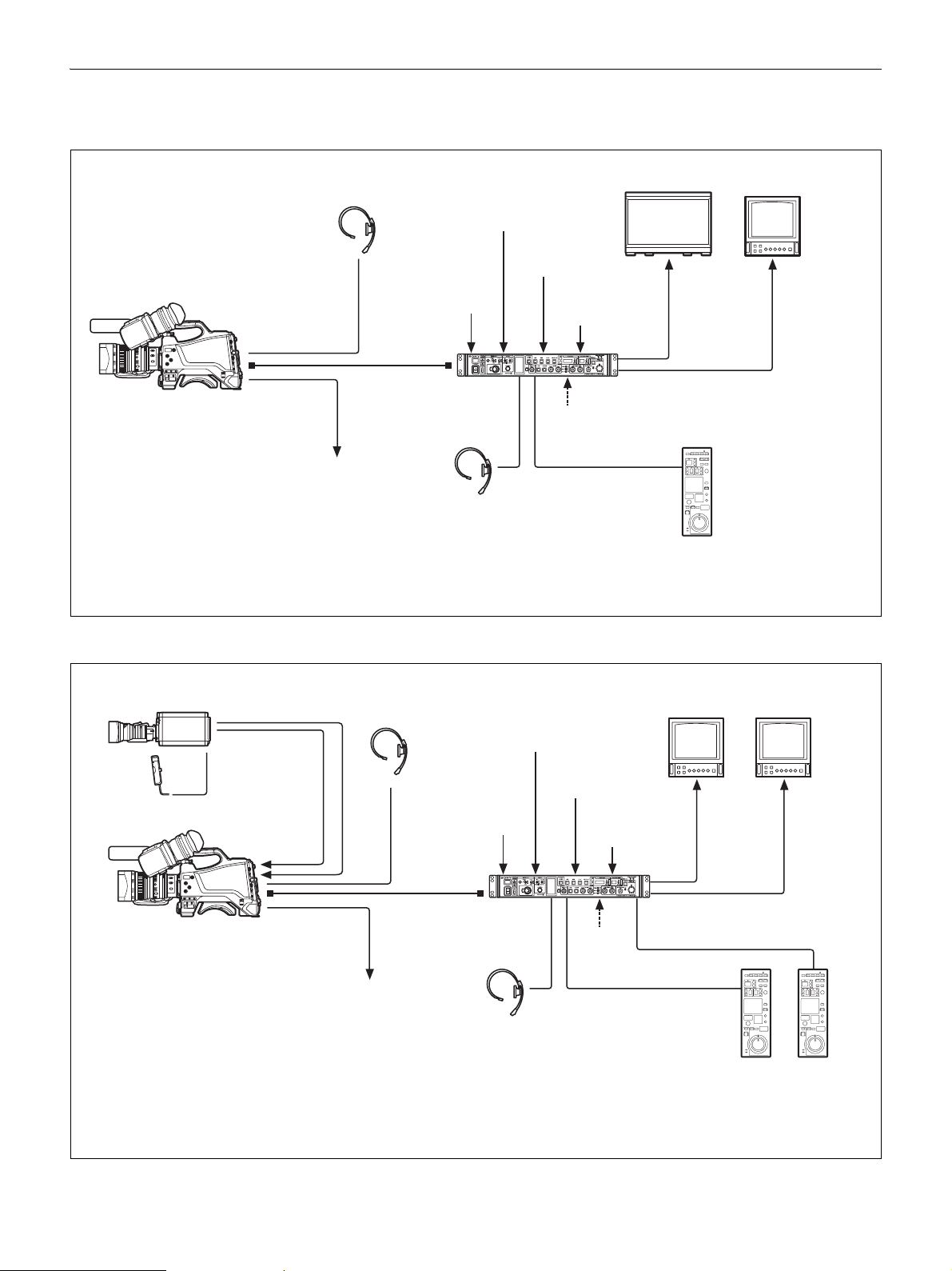
System Configuration Examples
4K SDR and HD SDR signal operation (HXC-FB80 connection)
Intercom
headset
Optical
composite
a)
cable
Sync signal
input
Return video
input
VBS
prompter
video input
HD prompter
video input
4K compatible
picture monitor
SLOT2:
4K/12G,
4K/3G, or
2K/3G video
output
Picture
monitor
SLOT1: HD
SDI/SD SDI
video output
b)
HXCU-FB80
HXC-FB80
HD Color Camera
Prompter video output
a) The maximum transmission distance is 600 m (1,970 ft) when Sony CCFN-25/50/100/150/200/250 Hybrid Fiber Cable is used.
b) 4K/3G output and 2K/3G output are not supported at the same time.
c) LAN cable connection is supported only for RCP-1500/1501/1530. Power must be supplied via a PoE hub or power supply must be
connected to EXT DC IN connector of RCP-1500/1501/1530.
4K/HD Camera
Control Unit
Intercom headset
AC power
CCA-5 cable/LAN
c)
cable
RCP-1000-series
Remote Control Panel
When sub camera is connected (HXC-FB80 connection)
HXC-P70 etc.
sub camera
AC-DN10
AC Adaptor
CCA-5 cable
HD SDI OUT
HD TRUNK
IN
b)
Intercom
headset
Optical
composite
a)
cable
Sync signal
input
Return video
input
VBS
prompter
video input
HD prompter
video input
HXCU-FB80
HXC-FB80
HD Color Camera
Prompter video output
a) The maximum transmission distance is 600 m (1,970 ft) when Sony CCFN-25/50/100/150/200/250 Hybrid Fiber Cable is used.
b) Operation supported when the signal format is not set to 1080/50P, 59.94P.
c) LAN cable connection is supported only for RCP-1500/1501/1530. Power must be supplied via a PoE hub or power supply must be
connected to EXT DC IN connector of RCP-1500/1501/1530.
d) For details about a D-Sub remote adapter, contact a Sony service representative.
4K/HD Camera
Control Unit
Intercom headset
AC power
CCA-5 cable/LAN
cable
Remote Control Panel
HD picture
monitor
D-Sub n 8 pin
c)
RCP-1000-series
SLOT2:
HD TRUNK
video
b)
output
Picture
monitor
SLOT1:
HD SDI/
SD SDI video
output
d)
4
Page 5
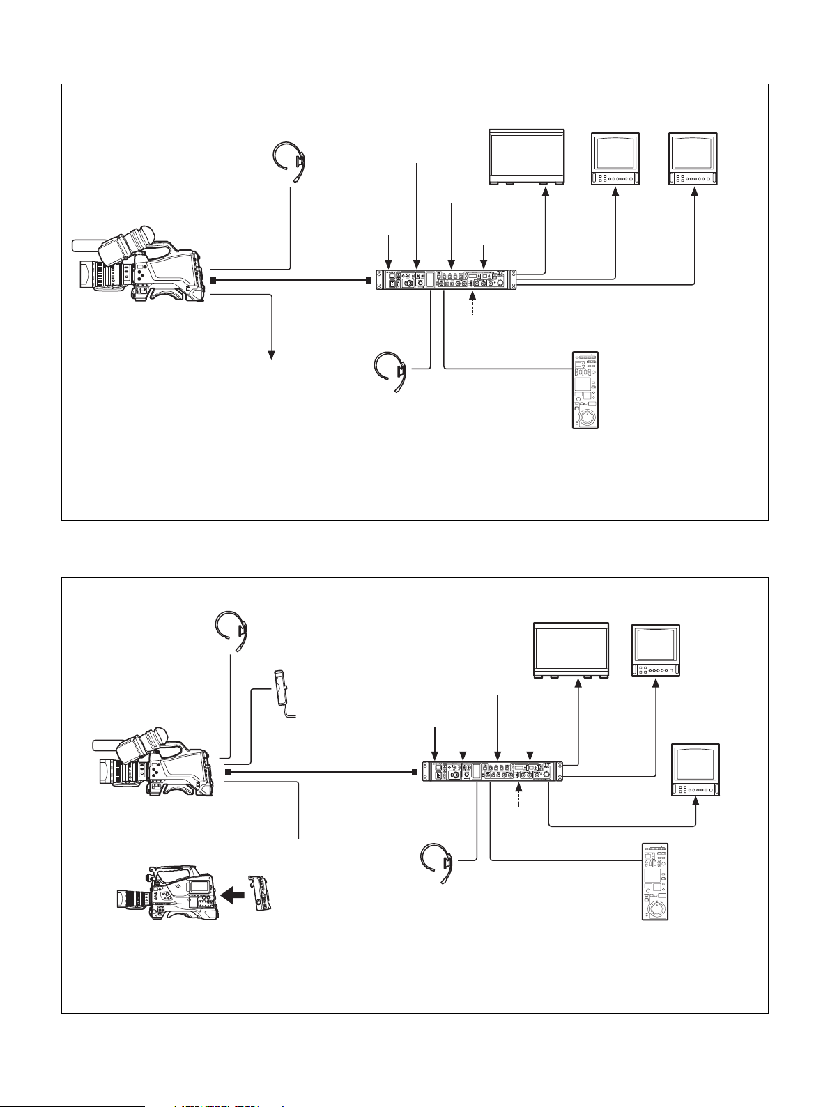
HD HDR and HD SDR signal operation (HXC-FB80 connection)
Intercom
headset
Sync signal
Optical
composite
a)
cable
input
HD HDR compatible
picture monitor
Return video
input
VBS
prompter
video input
HD prompter
video input
SLOT2:
HD HDR
video
output
HD picture
monitor
SLOT2:
HD SDR or
HD TRUNK
video output
Picture
monitor
HXCU-FB80
HXC-FB80
HD Color Camera
Prompter video output
a) The maximum transmission distance is 600 m (1,970 ft) when Sony CCFN-25/50/100/150/200/250 Hybrid Fiber Cable is used.
b) HD TRUNK output supported when the signal format is set to 1080/50i HDR, 59.94i HDR.
c) LAN cable connection is supported only for RCP-1500/1501/1530. Power must be supplied via a PoE hub or power supply must be
connected to EXT DC IN connector of RCP-1500/1501/1530.
4K/HD Camera
Control Unit
Intercom
headset
AC power
CCA-5 cable/LAN
c)
cable
RCP-1000-series
Remote Control Panel
b)
SLOT1:
HD SDI/SD
SDI video
output
Connection using single-mode optical fiber cable only
For information on the menu setting, see “Settings when Connecting with Only Single-Mode Optical Fiber Cable” (page 12).
4K compatible
picture monitor
HD prompter
video input
b)
SLOT2:
4K/3G video
output
SLOT2:
HD TRUNK
video output
HXC-FB80/FB75/E75
HD Color Camera
Intercom
headset
AC-DN2B/DN10
AC Adaptor
Single-mode optical fiber
cable (pair)
a)
Return video
input
VBS
prompter
video input
Sync signal input
HXCU-FB80
PXW-Z450/X500/X400/X320
Solid-State Memory Camcorder
PDW-850
Professional Disc Camcorder
a) The maximum transmission distance is 10 km (32,800 ft) when a general single-mode optical fiber cable with an LC connector is used.
b) Operation supported when connected to HXC-FB80.
c) Operation supported when connected to HXC-FB80 and the signal format is not set to 1080/50P, 59.94P.
d) LAN cable connection is supported only for RCP-1500/1501/1530. Power must be supplied via a PoE hub or power supply must be connected
or
Prompter
video output
CA-FB70
HD Camera Adaptor
to EXT DC IN connector of RCP-1500/1501/1530.
4K/HD Camera
Control Unit
Intercom
headset
AC power
CCA-5 cable/LAN cable
SLOT1: HD SDI/SD
SDI video output
RCP-1000-series
Remote Control Panel
b)
d)
HD picture
monitor
Picture
monitor
c)
5
Page 6
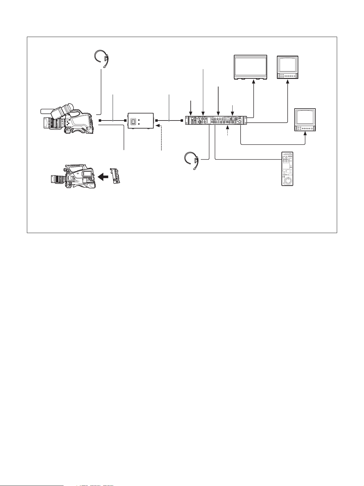
Connection using the HXCE-FB70 Power Supply Unit
Intercom
headset
4K compatible
picture monitor
Return video
input
HD picture
monitor
VBS
prompter
video input
HD prompter
video input
b)
AC power
CCA-5 cable/LAN cable
RCP-1000 series
Remote Control Panel
SLOT2:
4K/3G video
c)
output
SLOT2:
HD TRUNK
video output
SLOT1: HD SDI/SD
SDI video output
e)
Picture
monitor
d)
HXC-FB80/FB75/E75
HD Color Camera
or
PXW-Z450/X500/X400/X320
Solid-State Memory Camcorder
PDW-850
Professional Disc Camcorder
Optical composite
a)
cable
HXCE-FB70
Power Supply
Unit
Prompter
video output
CA-FB70
HD Camera
Adaptor
Singlemode optical
fiber cable
4K/HD Camera
AC power
b)
Sync signal
input
HXCU-FB80
Control Unit
Intercom headset
a) The maximum transmission distance is 250 m (820 ft) when Sony CCFN-25/50/100/150/200/250 Hybrid Fiber Cable is used.
b) The maximum transmission distance is 10 km (32,800 ft) when a general single-mode optical fiber cable with an LC connector is used.
c) Operation supported when connected to HXC-FB80.
d) Operation supported when connected to HXC-FB80 and the signal format is not set to 1080/50P, 59.94P.
e) LAN cable connection is supported only for RCP-1500/1501/1530. Power must be supplied via a PoE hub or power supply must be
connected to EXT DC IN connector of RCP-1500/1501/1530.
6
Page 7
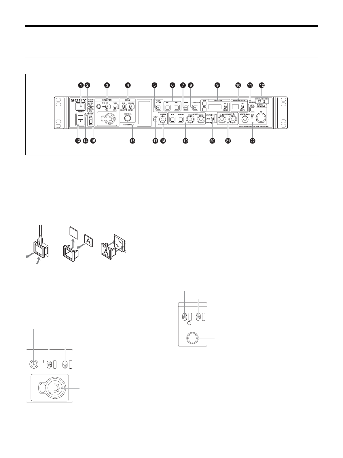
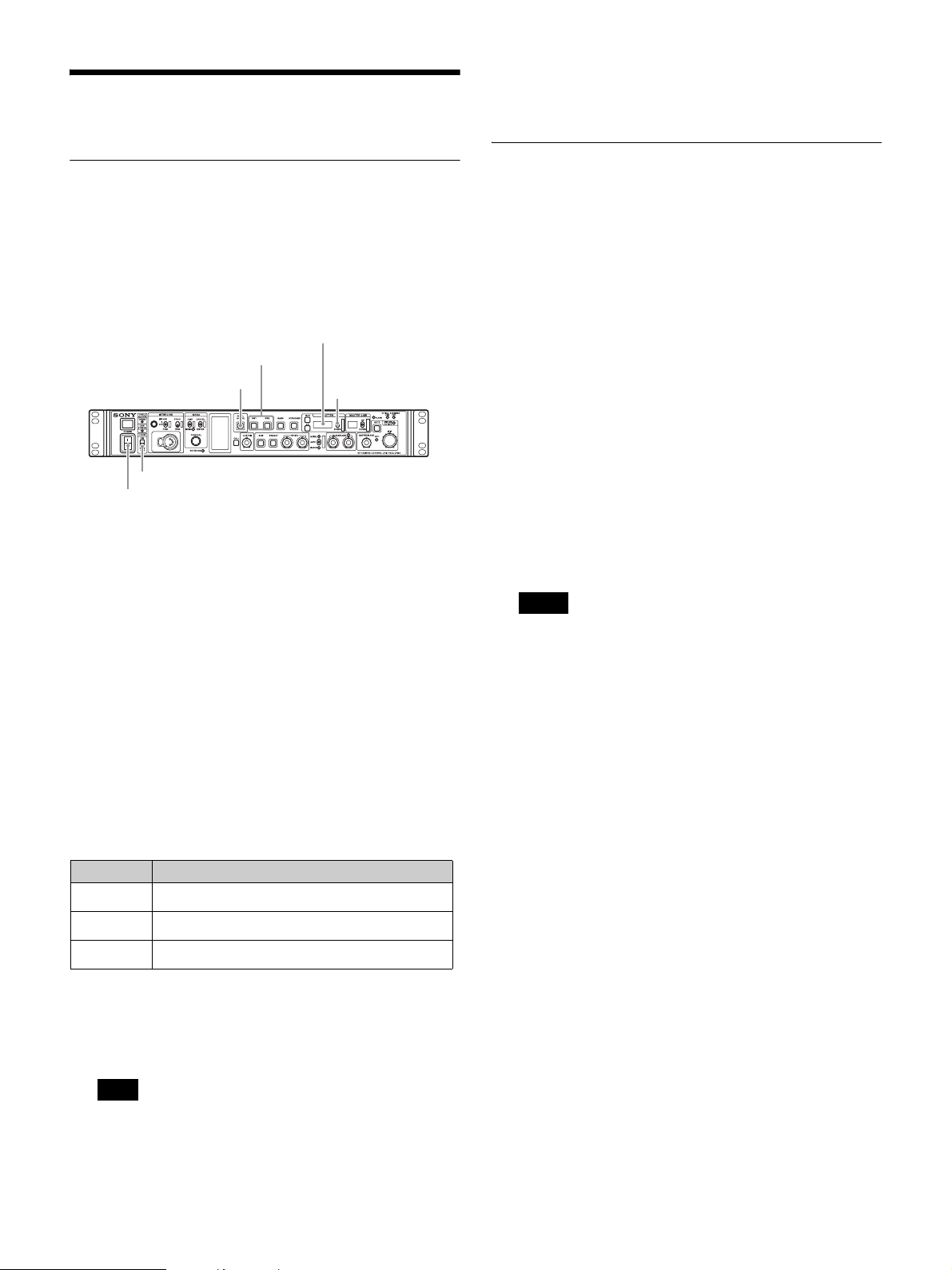
Locations and Functions of Parts
Front Panel
a Tally light
Turns on red to indicate a red tally signal is being received
(such as when the picture from the camera connected to the
CCU is being used). When the CALL button on the camera or
the RCP-1000 series Remote Control Panel is pressed, the
light turns off if lit or turns on if not lit.
Turns on green to indicate a green tally signal is being
received.
A number plate supplied with the CCU can be attached here
(see the following figure).
b CABLE ALARM indicators
OPEN: Turns on when a camera is not connected (open
circuit) to the CAMERA connector on the rear panel via a fiber
cable.
It flashes when there is a problem with the transmission
between the camera and the CCU.
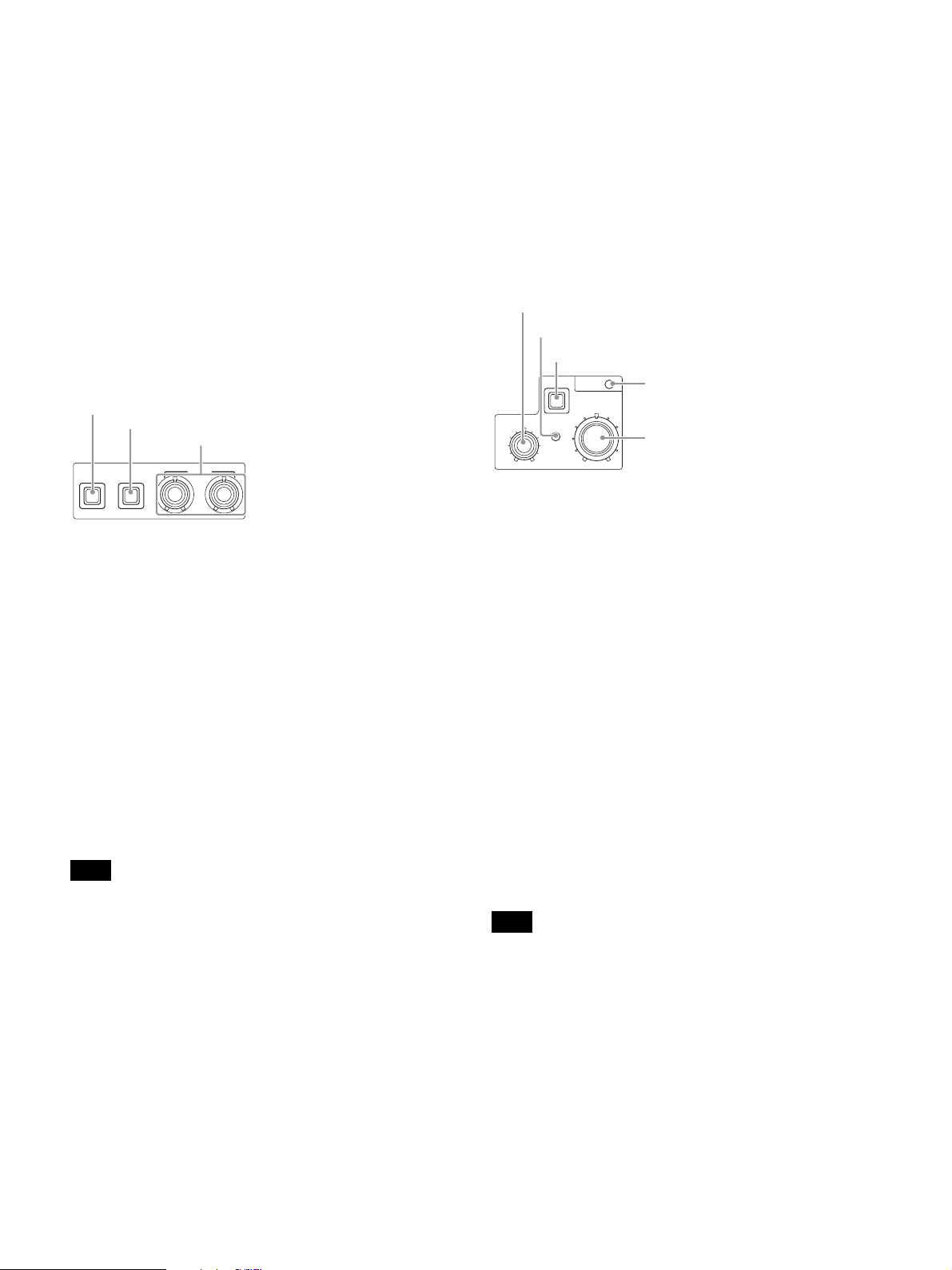
c INTERCOM audio input/output and control block
INTERCOM (intercom adjustment) knob
MIC/PGM (microphone/program) switch
INTERCOM (intercom select) switch
INTERCOM
MIC-ON
OFF
PGM
PROD
ENG
INTERCOM connector
• INTERCOM (intercom adjustment) knob
Adjusts the receiver audio level of the intercom.
• MIC/PGM (microphone/program) switch
ON: Turns the headset microphone on.
OFF: Turns the headset microphone off.
PGM: Selects program audio output. In this mode, the
INTERCOM knob adjusts the headset program audio level.
• INTERCOM (intercom select) switch
Selects the intercom signal input/output connection source for
the INTERCOM connector on the front panel.
PROD: Connects the producer line.
ENG: Connects the engineer line.
• INTERCOM connector (XLR 5-pin)
Connects the intercom headset.
For information about pin assignment, see “INTERCOM
connector” (page 36) in “Pin Assignment”.
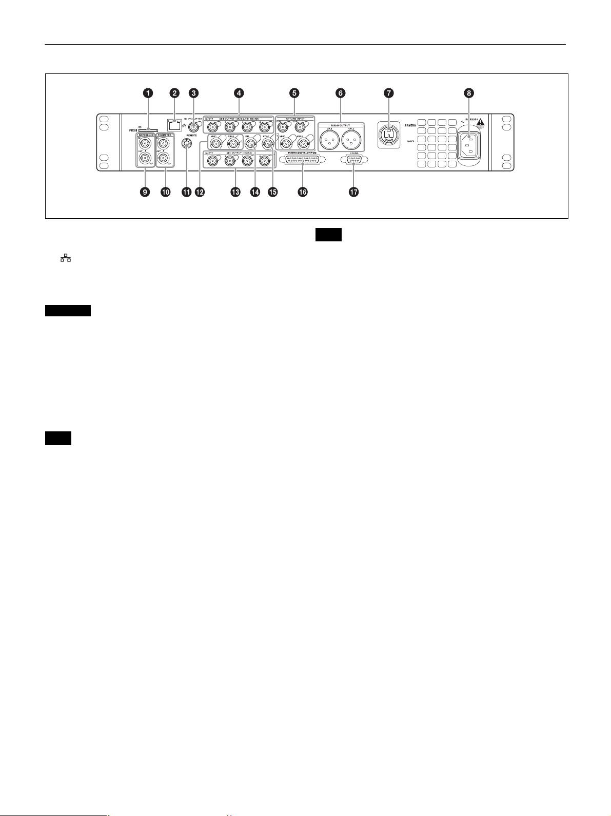
d MENU control block
DISP/MENU (display/menu) lever and indicator
CANCEL/ENTER lever
MENU
DISP CANCEL
MENU ENTER
CONTROL
CONTROL knob
• DISP/MENU (display/menu) lever and indicator
Selects the status display or setup menu display. In setup
menu mode, the indicator turns on.
• CANCEL/ENTER lever
In setup menu mode, used to cancel and enter settings.
• CONTROL knob (rotary encoder)
In status screen mode, used to change the displayed page. In
setup menu mode, used to move the cursor on a page and to
change menu settings.
7
Page 8

Pressing the CONTROL knob performs the same function as
setting the CANCEL/ENTER lever to the ENTER position.
e PANEL ACTIVE button
Activates the control panel to control the camera connected to
the CCU (panel active state). When the button is lit, the
IRIS/MB ACTIVE indicator also turns on simultaneously.
When the button is not lit, the panel is deactivated (panel lock
state) to prevent inadvertent operation.
f SW1, SW2 (assignable switch 1, 2) buttons
Controls the function assigned to each button on the <FRONT
PANEL 1> page in the CCU CONFIGURATION menu. The
button light turns on/off as the assigned function is switched
on/off.
For details, see “ASSIGNABLE/CUSTOM” (page 31) on
<FRONT PANEL 1>.
g BARS (color bars) button
Switches on the color bar signal output to the monitor
connected to the CCU (button light turns on). Pressing the
button again restores the previous signal output.
h STANDARD button
Stores the current camera settings as the reference file data
values in the camera (button light turns on for a few seconds).
While the button is lit, pressing the button again cancels the
operation and restores the previous data values.
i SHUTTER control block
Controls the shutter settings.
ON button
ECS (extended clear scan) button
Display
UP/DOWN lever
ECS
ON
•ON button
SHUTTER
UP
DOWN
Switches the normal shutter function, extended clear scan
function, or slow shutter function on/off (button light turns
on/off).
• ECS (extended clear scan) button
Switches the extended clear scan mode on/off (button light
turns on/off).
•Display
When the ECS button is lit: Displays the clear scan frequency.
When the ECS button is not lit: Displays the shutter speed.
The indicator is not displayed when auto shutter is on.
•UP/DOWN lever
When the ECS button is lit: Adjusts the clear scan frequency.
UP increases the frequency, and DOWN decreases the
frequency.
When the ECS button is not lit: Adjusts the shutter speed. UP
increases the shutter speed, and DOWN decreases the
shutter speed.
The number of frames at slow shutter speed increases when
the lever is in the UP position, and decreases in the DOWN
position.
Holding the lever UP or DOWN advances the setting in that
direction.
j MASTER GAIN control block
Controls the video output signal gain in response to the
lighting of the subject.
Display
UP/DOWN lever
MASTER GAIN
UP
DOWN
•Display
Displays the video output signal gain setting (dB units).
The indicator is not displayed when auto gain (AGC) is on.
• UP/DOWN lever
Adjusts the video output signal gain setting (dB units).
UP increases the gain, and DOWN decreases the gain.
Holding the lever UP or DOWN advances the setting in that
direction.
k ALARM indicator
Lights up red to indicate an error in the CCU or camera
system.
l OPTICAL CONDITION CAM/CCU (optical reception)
indicator
The CAM indicator shows the reception status of the
connected camera adaptor, and the CCU indicator shows the
reception status of the unit.
Green: The reception level is good.
Orange: The reception level is low.
Red: The reception level is extremely low.
Off: A transmission error has occurred.
m POWER switch
Switches the power for the entire system on and off, including
the CCU, camera, and the RCP-1000-series Remote Control
Panel connected to the REMOTE connector on the rear panel.
Pressing the “?” side turns the camera system on, and
pressing the “a” side turns it off.
n CAM POWER indicator
Turns on when power is supplied to the camera.
o LOCK switch
Locks the buttons on the front panel. Select the desired
buttons to be locked on the <FRONT PANEL 3> page in the
CCU CONFIGURATION menu.
For details, see “<FRONT PANEL 3>” (page 32).
p NETWORK indicator
Displays the network system connection status.
On: Indicates that external control equipment (RCP-1000-
series Remote Control Panel or other device) is
connected.
Flashing: Indicates a connection problem with the external
control equipment (RCP-1000-series Remote Control
Panel or other device).
Off: Indicates that a LAN cable is not connected or that the
network system connection parameters have not been set.
8
Page 9
For details, see “Network diagnostics” (page 18) and
“NETWORK SETTINGS menu” (page 33).
q CALL button
Sends a call signal to the camera connected to the CCU and
any external controller (such as the RCP-1000-series Remote
Control Panel).
The CALL button is commonly used to raise the camera
operator or external control equipment operators on the
intercom.
r CUSTOM (custom volume) knob
Controls the function assigned to the knob on the <FRONT
PANEL 1> page in the CCU CONFIGURATION menu. Turning
the knob adjusts the assigned function.
For details, see “VOLUME” (page 31) on <FRONT PANEL 1>
and “CUSTOM” (page 32) on <FRONT PANEL 2>.
s White balance adjustment control block
ATW (auto tracing white balance) button
PRESET (white balance preset) button
WHITE (white balance manual adjustment) knobs
The indicator operating mode (on/off function) can be set on
the <FRONT PANEL 1> page in the CCU CONFIGURATION
menu.
The adjustment can be set to black balance or flare balance
adjustment in relative or absolute value mode on the <FRONT
PANEL 1> page in the CCU CONFIGURATION menu. The
default value is black balance adjustment in relative value
mode.
For details, see “R/B BLACK” (page 31) on <FRONT PANEL
1> and “R/B BLACK” (page 32) on <FRONT PANEL 2>.
v IRIS/MASTER BLACK adjustment control block
MASTER BLACK (master black adjustment) knob
EXT (lens extender) indicator
AUTO (auto iris) button
MASTER BLACK
AUTO
EXT
IRIS/MB
ACTIVE
IRIS
IRIS/MB ACTIVE (iris/master black active)
indicator
IRIS (iris adjustment) knob
ATW PRESET
• ATW (auto tracing white balance) button
WHITE
The white balance is automatically adjusted in response to the
lighting conditions while this button is turned on and lit.
• PRESET (white balance preset) button
The white balance is automatically adjusted with a 3200K
color temperature preset value while this button is turned on
and lit.
• WHITE (white balance manual adjustment) knobs
Adjusts the white balance manually. The left knob adjusts the
R coefficient, and the right knob adjusts the B coefficient.
The adjustment can be set to relative or absolute value mode
on the <FRONT PANEL 1> page in the CCU
CONFIGURATION menu. The default value is relative value
mode.
For details, see “R/B WHITE” (page 31) on <FRONT PANEL
1> and “R/B WHITE” (page 32) on <FRONT PANEL 2>.
Note
When the ATW button is lit, the WHITE knobs are deactivated.
t AUTO WHITE/BLACK (white balance/black balance
auto adjustment) lever
Initiates the white balance or black balance auto adjustment
function.
WHITE automatically adjusts the white balance, and BLACK
automatically adjusts the black balance.
u BLACK/FLARE (black balance/flare balance manual
adjustment) knobs and indicator
Adjusts the black balance and flare balance manually.
When the indicator is not lit, the knobs adjust the black
balance. When the indicator is lit, the knobs adjust the flare
balance. The left knob adjusts the R coefficient, and the right
knob adjusts the B coefficient.
• MASTER BLACK (master black adjustment) knob
Adjusts the master black manually.
The adjustment can be set to relative or absolute value mode
on the <FRONT PANEL 1> page in the CCU
CONFIGURATION menu. The default value is relative value
mode.
For details, see “M BLACK” (page 31) on <FRONT PANEL 1>
and “M BLACK” (page 32) on <FRONT PANEL 2>.
• EXT (lens extender) indicator
Turns on to indicate that the lens extender is in-use on the
camera.
• AUTO (auto iris) button
Switches the lens auto iris adjustment function on/off (button
light turns on/off). The iris is automatically adjusted in
response to the input light level.
When the button is not lit, the iris is adjusted manually.
• IRIS/MB ACTIVE (iris/master black active) indicator
Indicates, when lit, that the iris and master black controls are
active (in panel active state set by the PANEL ACTIVE button).
When the indicator is lit, the iris and master black can be
adjusted from the CCU.
Note
The indicator is not lit when the iris and master black controls in the
RCP-1000-series Remote Control Panel are active.
• IRIS (iris adjustment) knob
When the AUTO button is not lit: Adjusts the lens iris manually.
When the AUTO button is lit: Finely adjusts the auto adjusted
iris value.
The adjustment can be set to relative or absolute value mode
on the <FRONT PANEL 1> page in the CCU
CONFIGURATION menu. The default value is absolute value
mode.
For details, see “IRIS” (page 31) on <FRONT PANEL 1> and
“IRIS” (page 32) on <FRONT PANEL 2>.
9
Page 10
Rear Panel
a “Memory Stick” slot
For service use only.
b LAN jack (RJ-45, 8-pin)
Connects to a LAN hub (10BASE-T/100BASE-TX), when
using a network connection, via a LAN cable (shielded type,
category 5 or higher).
CAUTION
For safety, do not connect the connector for peripheral device wiring
that might have excessive voltage to this port.
Follow the instructions for this port.
c HD PROMPTER (HD teleprompter connectors) (BNC
type)
When a camera that supports an HD teleprompter function is
connected to the CAMERA connector, the HD-SDI signal input
on this connector is output from the SDI I/O connector of the
camera.
Note
Input an HD-SDI signal having frequency synchronization with the
camera control unit.
d SLOT2, SDI OUTPUT 1 to 4 (4K/3G/HD TRUNK output)
connectors (BNC type)
Outputs the camera signal as 12G SDI signal, 3G SDI signal,
or 1.5G signal (HD TRUNK only).
e RETURN INPUT SDI1, SDI2, VBS1, VBS2 (VBS/SDI
return video) connectors (BNC type)
Inputs the VBS return video signals (2-system), HD SDI or SD
SDI return video signals (2-system).
f AUDIO OUTPUT CH-1, CH-2 connectors (XLR 3-pin)
Outputs audio signals from the camera AUDIO 1 IN and
AUDIO 2 IN connectors.
g CAMERA connector (optical fiber connector)
Connect to the target camera or CA-FB70 HD Camera
Adaptor.
When you use an optical composite cable for connection,
power supply, all camera signals, such as control signal, video
signal and audio signals can be transmitted.
When you use only single-mode optical fiber cables for
connection, all signals (except power supply) can be
transmitted by a pair of single-mode optical fiber cables.
For details about pin assignment, see “CAMERA connector”
(page 37).
Note
If the terminations of the single-mode optical fiber cable or optical
composite cable are contaminated with dust, etc., transmission errors
may occur. Be sure to replace the cap that came with the cable over
the termination when a cable is not in use.
h AC supply input connector
Connects to the AC supply via the specified power cord
(optional). A plug holder (optional) can be used to secure the
power cord to the CCU.
i REFERENCE (reference input) connectors (BNC type)
IN: Inputs an HD tri-level reference sync signal or SD
reference sync signal (black burst signal) for external sync.
OUT: The input signal is output from the other connector as-is
(loop-through output). If the loop-through output is not
used, it is automatically connected to a 75 Ω terminator.
j PROMPTER (teleprompter input) connectors (BNC
type)
IN: Inputs the VBS signal for the teleprompter.
OUT: The input signal is output from the other connector as-is
(loop-through output). If the loop-through output is not
used, it is automatically connected to a 75 Ω terminator.
k REMOTE connector (8-pin)
Transmits and receives control signals from the RCP-1000series Remote Control Panel via a CCA-5 cable (optional). It
also supplies power when connected to an RCP-1000-series
Remote Control Panel.
l VBS 1, 2 (composite video signal 1, 2) connectors
(BNC type)
Outputs (2-system) the camera signals in composite signal
format.
m SLOT1, SDI OUTPUT 1 to 4 connectors (BNC type)
Outputs the camera signals in HD SDI or SD SDI signal
format.
The SDI OUTPUT 3 and SDI OUTPUT 4 connectors can also
output signals with superimposed character or marker display.
n PIX (picture monitor output) connector (BNC type)
Outputs a video signal for a picture monitor. It can also output
a signal with superimposed character display.
o SYNC (sync signal output) connector
Outputs a sync signal for connection to the sync signal input
connector of a waveform monitor or picture monitor.
10
Page 11

p INTERCOM/TALLY/PGM (intercom/tally/program
audio) connector (D-sub 25-pin)
Transmits and receives the various intercom, tally, and
program audio signals. It connects to the
intercom/tally/program audio connector of the intercom
system.
For information about pin assignment, see
“INTERCOM/TALLY/PGM connector” (page 36) in “Pin
Assignment”.
Note
Depending on the PGM MIX LEVEL settings of the camera, PGM
signal may leak into the INTERCOM output. Turn the PGM MIX
LEVEL settings down to reduce the signal interference.
q TRUNK connector (D-sub 9-pin, RS-232C/RS-422A
standard)
Connects to an external device to provide a communication
path via the CCU between that device and another external
device connected to the TRUNK connector on the camera.
You can switch between RS-232C and RS-422A settings in the
menu.
For information about pin assignment, see “TRUNK
connector” (page 37) in “Pin Assignment”.
11
Page 12
Setup
Area Settings
“- - - - ” appears in the SHUTTER display five seconds after
setting. Area settings are stored and the units switches to
normal mode.
Settings when Connecting with Only
Single-Mode Optical Fiber Cable
Before using the unit
When you use this unit for the first time, area setting is
required.
Setting the area
SHUTTER display
SW1, SW2 buttons
PANEL ACTIVE button
LOCK switch
POWER switch
UP/DOWN lever
1 Turn t h e powe r o n.
2 Set the LOCK switch to OFF and make sure that the
PANEL ACTIVE button is not illuminated.
If the PANEL ACTIVE button lights up, press the button to
turn the light off.
3 Press and hold down the SW1 and SW2 buttons at the
same time for more than two seconds.
The unit switches to setting mode and selectable setting
values appear in the SHUTTER display.
4 Release the buttons after the unit switches to setting
mode.
LASER DIODE (optical output) setting
When you use only single-mode optical fiber cable to connect
the HD camera adaptor to this unit, configure the optical output
setting in the unit.
Setting LASER DIODE
1 Connect the unit and the HD camera adaptor by a
single-mode optical fiber cable.
2 Set the POWER switch of this unit to ON.
3 Display the menu.
For information about setting menu items, see “Setup
Menu” (page 19).
4 Set the optical output to ON.
Display the <OUTPUT SELECT> S01 page of the
SYSTEM OPERATION menu, then set LASER DIODE to
ON.
Notes
• This setting is unnecessary when you use optical composite
cables.
• In the factory default setting, LASER DIODE is set to OFF
when this unit starts up. If you want to retain the LASER
DIODE setting you have previously set, from the CCU
CONFIGURATION menu, select <OTHERS> C14 page,
LASER DIODE ON BACKUP, then set to ENABLE.
• Use general, single-mode optical fiber cables with an LC
connector for connection. For details, contact a Sony sales
representative.
5 Select the desired area, using the UP/DOWN lever,
within five seconds after the unit switches to setting
mode.
Setting Area
60i5
60i
50i
a) NTSC composite video signal output with black setup (7.5 IRE).
System frequency: 59.94i
b) NTSC composite video signal output with no black setup. System
frequency: 59.94i
c) PAL composite video signal output. System frequency: 50i
Note
Setting mode is deactivated unless setup starts within five
seconds after the unit switches to setting mode. Follow step 3
again to activate setting mode.
NTSC (except Japan)
NTSC (Japan)
c)
PA L
a)
b)
12
Page 13

Signal Format Setting
Output Signal Setting
You can set the signal format to use in the menu.
For details about menu operations, see “To display the CCU
MENU page” (page 19).
The CAMERA FORMAT settings available for selection vary
depending on the HD HDR mode setting.
For details about HD HDR mode, see “HD HDR Mode Setting”
(page 14).
HD HDR mode is set to OFF by default.
1 Display the CCU MENU page.
2 Display the MULTI FORMAT page of the SYSTEM
OPERATION menu.
<MULTI FORMAT> S03 TOP
FREQUENCY: 59.94Hz
(525 NTSC)
CAMERA FORMAT
: 1080/59.94P
(OETF : SDR)
3 Refer to the following table and set FREQUENCY and
CAMERA FORMAT.
FREQUENCY CAMERA
FORMAT
59.94Hz
(525 NTSC)
50Hz
(625 PAL)
Note
If the area setting is changed after configuring these items, the
signal format automatically switches to 1080/59.94I or 1080/50I
according to the FREQUENCY setting corresponding to the area
setting.
1080/59.94I NTSC/NTSC (Japan) format
1080/29.97PsF
1080/59.94P HXC-FB80 connection only
1080/23.98PsF HXC-FB80 connection only
720/59.94P
1080/50I PAL format
1080/25PsF
1080/50P HXC-FB80 connection only
720/50P
Remarks
You can set the SDI signal output of SLOT1 and SLOT2
connectors in the menu.
For details about menu operations, see “To display the CCU
MENU page” (page 19).
The method varies depending on the selected HD HDR mode.
For details about HD HDR mode, see “HD HDR Mode Setting”
(page 14).
When HD HDR mode is OFF
1 Display the CCU MENU page.
2 Display the OUTPUT FORMAT page of the SYSTEM
OPERATION menu.
<OUTPUT FORMAT> S04 TOP
SLOT-NO
1-1&2: 1080/59.94I
3&4: M525/59.94I
2-1&2: 4K/59.94P 2SI
3&4: 4K/59.94P 2SI
3G-SDI: LEVEL A
3 Refer to the following table and set the output signal
for each slot under SLOT-NO.
SLOT1 connector
Values in bold are valid when connected with HXC-FB80
only.
CAMERA
FORMAT setting
1080/59.94P
(OETF: SDR)
1080/29.97PsF
(OETF: SDR)
1080/23.98PsF
(OETF: SDR)
1080/50P
(OETF: SDR)
1080/25PsF
(OETF: SDR)
1080/59.94I
(OETF: SDR)
1080/50I
(OETF: SDR)
720/59.94P
(OETF: SDR)
1-1&2 (SDI-1, 2)
setting
1080/59.94I M1080/59.94I
525/59.94I M525/59.94I
1080/29.97PsF M1080/29.97PsF
525/29.97PsF M525/29.97PsF
1080/23.98PsF M1080/23.98PsF
1080/59.94I M1080/59.94I
525/59.94I M1080/23.98PsF
1080/50i M1080/50I
625/50i M625/50I
1080/25PsF M1080/25PsF
625/25PsF M625/25PsF
1080/59.94I M1080/59.94I
525/59.94I M525/59.94I
1080/50I M1080/50I
625/50I M625/50I
720/59.94P M720/59.94P
525/59.94I M525/59.94I
1-3&4 (SDI-3, 4)
setting
M525/59.94I
M525/59.94I
M1080/59.94I
M525/59.94I
13
Page 14

CAMERA
FORMAT setting
720/50P
(OETF: SDR)
1-1&2 (SDI-1, 2)
setting
720/50P M720/50P
625/50I M625/50I
1-3&4 (SDI-3, 4)
setting
3 Refer to the following table and set the output signal
for each slot under SLOT-NO.
SLOT1 connector
All output signals are SDR signals.
SLOT2 connector
Valid when connected with HXC-FB80 only.
CAMERA
FORMAT setting
1080/59.94P
(OETF: SDR)
1080/29.97PsF
(OETF: SDR)
1080/23.98PsF
(OETF: SDR)
1080/50P
(OETF: SDR)
1080/25PsF
(OETF: SDR)
1080/59.94I
(OETF: SDR)
1080/50I
(OETF: SDR)
720/59.94P
(OETF: SDR)
720/50P
(OETF: SDR)
2-1&2 (SDI-1, 2)
setting
1080/59.94P
4K/59.94P SQD
4K/59.94P 2SI
4K/59.94P 12G
– 1080/29.97PsF
– 1080/23.98PsF
1080/50P
4K/50P SQD
4K/50P 2SI
4K/50P 12G
– 1080/25PsF
– 1080/59.94I
– 1080/50I
– 720/59.94P
– 720/50P
a)
a)
a) b)
a) b)
b)
a) b)
a) b)
b)
2-3&4 (SDI-3, 4)
setting
1080/59.94P
4K/59.94P SQD
4K/59.94P 2SI
1080/59.94P
1080/50P
4K/50P SQD
4K/50P 2SI
1080/50P
CAMERA
FORMAT setting
1080/59.94P
(OETF:HLG_LIVE)
1080/50P
a)
a) b)
a) b)
a)
c)
c)
a)
a) b)
a) b)
a)
c)
c)
c)
c)
c)
(OETF:HLG_LIVE)
1080/59.94I
(OETF:HLG_LIVE)
1080/50I
(OETF:HLG_LIVE)
SLOT2 connector
CAMERA
FORMAT setting
1080/59.94P
(OETF:HLG_LIVE)
1080/50P
(OETF:HLG_LIVE)
1080/59.94I
(OETF:HLG_LIVE)
1080/50I
(OETF:HLG_LIVE)
a) Output as 3G-SDI. Select SMPTE 425 Level-A or SMPTE 425
Level-B.
b) HDR signal is output.
c) SDR signal is output.
d) HD-TRUNK is output when HD TRUNK is set to ON.
1-1&2 (SDI-1, 2)
setting
1080/59.94I M1080/59.94I
525/59.94I M525/59.94I
1080/50I M1080/50I
625/50I M625/50I
1080/59.94I M1080/59.94I
525/59.94I M525/59.94I
1080/50I M1080/50I
625/50I M625/50I
1-1&2 (SDI-1, 2)
setting
1080/59.94P
1080/50P
1080/59.94I
1080/50I
a)
b)
1-3&4 (SDI-3, 4)
setting
1-3&4 (SDI-3, 4)
setting
a) b)1080/59.94P a)
b)
1080/50P a)
b)
1080/59.94I
1080/50I
c) d)
c)
c)
c) d)
a) Output as 3G-SDI. Select SMPTE 425 Level-A or SMPTE 425
Level-B.
b) Select BT.709 or BT.2020 for the color space.
c) HD-TRUNK is output.
When HD HDR mode is LIVE HDR
Valid when connected with HXC-FB80 only.
1 Display the CCU MENU page.
2 Display the OUTPUT FORMAT page of the SYSTEM
OPERATION menu.
<OUTPUT FORMAT> S04 TOP
SLOT-NO
1-1&2: 1080/59.94I
3&4: M1080/59.94P
2-1&2: 1080/59.94P
(OETF : HLG_LIVE)
3&4: 1080/59.94P
(OETF : SDR)
3G-SDI: Level1 A
HD HDR Mode Setting
HD HDR mode must be enabled on the unit for HD HDR
operation when the HXC-FB80 is connected to the unit.
Note
The HXC-FB80 software must be upgraded to V1.10 or later for
operation in this mode.
1 Connect the HXC-FB80 to the unit.
2 Set the POWER switch of this unit to ON.
3 Display the CCU MENU page.
14
Page 15

4 Change the <HD HDR> (S07) setting in the SYSTEM
OPERATION menu to LIVE HDR.
<HD HDR> S07 TOP
HDR MODE : cOFF
SDR GAIN : -----HDR BLACK OFFSET: -----
5 Move the cursor to YES under MODE CHANGE OK?,
and press the CONTROL button.
<HD HDR> S07 TOP
MODE CHANGE OK? cYES NO
HDR MODE :?OFF
cLIVE_HDR
SDR GAIN : -----HDR BLACK OFFSET: -----
The unit restarts.
LIVE HDR operation is enabled after restarting.
Notes
• 4K signal output is disabled when the HD HDR mode is set to LIVE
HDR.
For details, see “Output Signal Setting” (page 13).
• The signal format of the connected camera and output signal format
change automatically when the HD HDR mode is changed.
- When the mode is switched from OFF to LIVE HDR, the format
changes to 1080P HDR from 1080P format, or to 1080I HDR from
formats other than 1080P.
- When the mode is switched from LIVE HDR to OFF, the format
changes to 1080P from 1080P HDR format, or to 1080I from
formats other than 1080P HDR.
15
Page 16

Camera settings
Status Display
The CCU system status can be monitored using a picture
monitor connected to the PIX output.
For details about checking and changing settings, see “Setup
Menu” (page 19).
Displaying the Status Screen
The status screen is controlled using the knob and levers in
the MENU control block on the front panel.
DISP/MENU lever and indicator
MENU
DISP CANCEL
MENU ENTER
CONTROL
CONTROL knob
To display the status screen
Set the DISP/MENU lever to the DISP position.
The most recently viewed status screen page is displayed
(when first powered on, the camera settings page is
displayed).
Turning the CONTROL knob changes the displayed page.
To exit the status screen display
In status screen display mode, set the DISP/MENU lever to the
DISP position.
Page 1
a
6dB 1/2000 OFF
ND:1 F:4.7 EX CC:A
b
cd
ef hg
a Gain value indicator
Displays the video output signal gain (dB units).
Becomes the AGC indicator when AGC is on.
b Shutter speed/Clear scan frequency indicator
Displays the shutter speed. When ECS is on, the clear scan
frequency is displayed.
At slow shutter speeds, the number of frames is displayed. In
auto shutter mode, AE (Auto Exposure) is displayed.
c Shutter/ECS/Slow shutter on/off indicator
Displays the shutter/ECS/slow shutter on/off state.
d Camera auto control information area
Top : Displays the Auto Setup category and execution status.
Bottom: Displays the execution item.
e ND filter indicator
Displays the current ND filter selection.
f F-stop value indicator
Displays the lens F-stop value (iris value).
g EX (lens extender) indicator
Displayed when the lens extender is in use.
Status Display Screen
The following information is displayed on the status display
screen.
• Camera settings
•System status
• CCU hardware diagnostics
• Camera system diagnostics
• Network diagnostics
• CCU AT board diagnostics
• CCU DPR board diagnostics
• Front panel diagnostics
• Camera hardware diagnostics
• ROM version information for major components
Notes
• Items that are turned off using the <DISPLAY> page settings of the
CCU CONFIGURATION menu are not displayed.
• A “-” mark is displayed for each item when a camera is not
connected.
h CC filter indicator
Displays the current CC filter selection.
Page 2
6dB 1/2000 OFF
White Black
R: 0 R: 0
G: 0 G: 0
B: 0 B: 0
M:0.0
BLK γ Flare
: 0 R: 0
DTL G: 0
: 0 B: 0
ND:1 F:4.7 EX
White: White balance R/G/B value
Black: Black balance R/G/B/Master value
BLK γ: Black gamma value
16
Page 17

Flare: Flare balance R/G/B value
DTL: Detail level
Note
The items are the same as those on “Page 1” (page 16) in the
“Camera settings” section.
System status
*System Status 1/2*
HXC-FB80 1080/59.94P
(OETF : HLG_LIVE)
Reference:Free Lock
SLOT1-1&2:1080/59.94I
SLOT1-3&4:1080/59.94I
SLOT2-1&2:4K/59.95P 2SI
(OETF : HLG_LIVE)
SLOT2-3&4:4K/59.95P 2SI
(OETF : SDR)
*System Status 2/2*
HXC-FB80 1080/59.94I
(OETF : HLG_LIVE)
Return-1 :SDI-1(HD)
Return-2 :SDI-2(SD)
Return-3 :VBS-1
Return-4 :FBS-2
The camera model name, format, and camera OETF
(HLG_LIVE or SDR) are displayed at the top of the page when
a camera is connected to the unit. A “---” mark is displayed
when a camera is not connected.
Reference: Reference signal format and lock status
SLOT1-1&2: SLOT1 SDI OUTPUT 1/2 connector output
format selection
SLOT1-3&4: SLOT1 SDI OUTPUT 3/4 connector output
format selection
SLOT2-1&2: SLOT2 SDI OUTPUT 1/2 connector output
format selection and connected camera OETF (HLG_LIVE
or SDR) indicator
SLOT2-3&4: SLOT2 SDI OUTPUT 3/4 connector output
format selection and connected camera OETF (HLG_LIVE
or SDR) indicator
Return-1: Return channel setting of Return 1
Return-2: Return channel setting of Return 2
Return-3: Return channel setting of Return 3
Return-4: Return channel setting of Return 4
CCU hardware diagnostics
*Diagnosis* 3/14
DPR :OK
AT :OK
Front Panel : OK
DPR: DPR board status
AT: AT board status
Front Panel: Front panel status
Camera system diagnostics
Page 1
*System Diag 1/3* 4/14
Optical Condition
CAMERA OK
CCU OK
Fan Power OK
Timer 0H
CCU Power OK
SerialNo 00000000
CAMERA: Camera light sensor status
CCU: CCU light sensor status
Fan Power: CCU power supply fan status
Timer: Elapsed time since power-on
CCU Power: CCU power supply status
SerialNo: CCU serial number
Page 2
*System Diag 2/3* 5/14
CAMERA Cable Connect
Data OK
Power OK
REMOTE Cable Connect
Data OK
Power OK
CAM
: ssxxxxxxb Green
CCU
: ssxxxxxxb Green
CAMERA Cable: Camera cable connection status
CAMERA Data: Camera data transmission status
CAMERA Power: Camera power supply status
REMOTE Cable: Remote device cable connection status
REMOTE Data: Remote device data transmission status
REMOTE Power: Remote device power supply status
CAM/CCU (light sensor level indicator): CAM displays
camera light sensor level, and CCU displays CCU light
sensor level.
Page 3
*System Diag 3/3* 6/14
Intercom
CCU FRONT ENG
PGM ON
CAMERA ENG
MIC ON
CAM MIC Gain
CH1(FRONT) 60
CH2(REAR) 60
SUB CMD --------
dB
dB
The camera Auto Setup category, and the corresponding
setup item and status are displayed at the top of the page.
Intercom CCU FRONT: CCU intercom selection
Intercom CAMERA: Camera intercom channel selection and
microphone status
CAM MIC Gain CH1 (FRONT): Amplifier gain for a
microphone connected to the camera AUDIO 1 IN
connector.
17
Page 18

CAM MIC Gain CH2 (REAR): Amplifier gain for a microphone
connected to the camera AUDIO 2 IN connector.
Network diagnostics
Page 1
*Network Diag 1/3* 7/14
MacAddress:000000-000000
Auto Negotiation: ON
Connection Speed:100M
Duplex Mode :HALF
Link Status :OK
MacAddress: MAC address stored in CCU EEPROM
Auto Negotiation: Auto negotiation setting
Connection Speed: Connection speed setting
Duplex Mode: Communication method setting
Link Status: Network connection status
CCU AT board diagnostics
*AT Diag* 10/14
SLOT2-1&2:4K/59.94P 2SI
SLOT2-3&4:4K/59.94P 2SI
SDI OUT:1 2 3 4
STATUS1 OK OK OK OK
STATUS2 OK OK OK OK
PLD Status :OK
AT :1.00
AT POWER :OK
SLOT2-1&2: SLOT2 SDI OUTPUT 1/2 connector output
format selection
SLOT2-3&4: SLOT2 SDI OUTPUT 3/4 connector output
format selection
SDI OUT STATUS: SLOT2 SDI OUTPUT1/2/3/4 status
PLD Status: PLD status
PLD AT: AT-PLD version
AT POWE R : AT board power supply status
CCU DPR board diagnostics
Page 2
*Network Diag 2/3* 8/14
CNS Mode :BRIGDE
CCU No. :1
CNS Mode: REMOTE and LAN connectors mode setting
CCU No.: CCU number setting
Page 3
*Network Diag 3/3* 9/14
IP Address
0. 0. 0. 0
Subnet Mask
0. 0. 0. 0
Default Gateway
0. 0. 0. 0
IP Address: CCU IP address setting
Subnet Mask: CCU subnet mask setting
Default Gateway: CCU default gateway setting
*DPR Diag* 11/14
Reference :HD
4K/HD CB
:BAR 16:9(100%)
SD CB :SMPTE
PLD Status:OK
SY :1.00
POST :1.00
IIC :OK
DPR POWER:OK
Reference: Reference signal setting
HD CB: HD color bar setting
SD CB: SD color bar setting
PLD Status: PLD status
PLD SY: SY-PLD version
PLD POST: POST-PLD version
IIC: IIC bus control status
DPR POWER: DPR board power supply status
Front panel diagnostics
*Front Panel Diag* 12/14
Assignable/Custom
SW1 :CAM POWER
SW2 :5600K
VOLUME :SD DTL Level
SW Bright:Normal
IIC :OK
Assignable/Custom SW1: Function assigned to the SW1
button
Assignable/Custom SW2: Function assigned to the SW2
button
Assignable/Custom VOLUME: Function assigned to the
CUSTOM knob
SW Bright: Button lights LED brightness setting
IIC: IIC bus control status
18
Page 19

Camera hardware diagnostics
*CAMERA Diag* 13/14
ALL BOARD OK
Displays the camera hardware status.
ROM version information
*ROM Version* 14/14
CAMERA HXC-FB80
1.00 XX.XX.XX
CCU HXCU-FB80
1.00 XX.XX.XX
CAMERA: Camera model name and ROM version
CCU: CCU model name and ROM version
Setup Menu
The CCU system and peripheral settings can be checked and
modified using a picture monitor connected to the PIX output.
Changing Menu Item Settings
The menu screen is controlled using the knob and levers in the
MENU control block on the front panel.
Setting the CANCEL/ENTER lever to the ENTER position and
pressing the CONTROL knob perform the same function.
DISP/MENU (display/menu) lever and indicator
CANCEL/ENTER lever
MENU
DISP CANCEL
MENU ENTER
CONTROL
CONTROL knob
To display a menu page
Set the DISP/MENU lever to the MENU position.
When first powered on, the CCU MENU page is displayed.
To display the CCU MENU page
In menu display mode, turn the CONTROL knob to move the
pointer (,) to TOP in the upper right corner of the menu page,
then press the CONTROL knob.
The CCU MENU showing the menu configuration is displayed.
** CCU MENU **
c SYSTEM OPERATION
CCU CONFIGURATION
NETWORK SETTINGS
Menu name Description
SYSTEM OPERATION Input/output signal format and
CCU CONFIGURATION CCU configuration settings
NETWORK SETTINGS Network-related settings
system-related settings
To select an item in the CCU MENU
Turn the CONTROL knob to move the pointer (,) up/down to
the desired menu item, then press the CONTROL knob.
The most recently viewed page in the selected menu is
displayed.
19
Page 20

To change the displayed page
1 Turn the CONTROL knob to move the pointer (,) to
the page number, then press the CONTROL knob.
The pointer (,) changes to a flashing question mark (?).
Flashing
<OUTPUT SELECT> ?S01 TOP
OUTPUT:*CAMERA
BAR
TEST1
TEST2
PIX:*ENC R G B
R&B G&B R&B RGB
LASER DIODE: (ON)
2 Turn the CONTROL knob to change the displayed
page to the desired page, then press the CONTROL
knob.
The question mark (?) changes back to the pointer (,).
Items on the page can now be selected and changed.
1 Move the text cursor to the input position, then press
the CONTROL knob.
A second cursor is displayed in the character list.
2 Turn the CONTROL knob to move the cursor to the
desired character, then press the CONTROL knob.
Repeat steps 1 and 2 to enter other characters.
• Select INS to insert a space character at the cursor
position.
• Select DEL to delete the character at the cursor
position.
• Select RET to return to step 1 without changing the
string.
• Entering the maximum number of characters (up to the
right edge) moves the cursor to ESC on the lower right
of the character list.
3 Turn the CONTROL knob to move the cursor to END,
then press the CONTROL knob.
The new input string is registered.
To cancel the character string setting
Turn the CONTROL knob to move the cursor to ESC, then
press the CONTROL knob.
To change a menu item setting
If a question mark (?) is displayed beside the page number,
press the CONTROL knob to restore the pointer (,). Items
on the page can now be selected and changed.
1 Turn the CONTROL knob to move the pointer (,) to
the desired item, then press the CONTROL knob.
The pointer (,) changes to a flashing question mark (?).
2 Turn the CONTROL knob to change the setting.
To cancel a changed setting
Set the CANCEL/ENTER lever to the CANCEL position
before pressing the CONTROL knob. The item is restored
to its current setting.
To suspend menu changes
Set the DISP/MENU lever to the MENU position to exit the
menu screen.
The DISP/MENU lever can be set to the MENU position
again to restart the operation.
3 Press the CONTROL knob.
The question mark (?) changes back to the pointer (,),
and the item setting is registered.
4 Repeat steps 1 to 3 to change other settings on the
same page.
To exit the menu display
In menu display mode, set the DISP/MENU lever to the MENU
position.
To enter a character string
Some menu items require a character string input.
Moving the pointer (,) to an item with a character string input
and pressing the CONTROL knob displays a rectangular
cursor and a list of selectable characters.
Turning the CONTROL knob moves the cursor between
characters.
The following menu item has character strings:
• CCU CONFIGURATION menu t <BAR CHARACTER>
page t BAR CHARACTER
20
Page 21

Menu Tree
SYSTEM OPERATION menu CCU CONFIGURATION menu
OUTPUT SELECT OUTPUT
(S01)
GENLOCK PHASE REFERENCE
(S02) GENLOCK
H STEP
COARSE
SC PHASE
V PHASE
SYNC OUT
MULTI FORMAT FREQUENCY
(S03)
OUTPUT FO RMAT
(S04)
SD ASPECT
(S05)
RETURN SET
(S06)
HD HDR
(S07)
PIX
LASER DIODE
CAMERA FORMAT
OETF
SLOT NO
1-1&2
1-3&4
2-1&2
2-3&4
3G-SDI
HD TRUNK
COLOR
SD ASPECT
SD LB SEL
H POSITION
CENTER
V POSITION
CENTER
H INTERP
V INTERP
RET-1
RET-2
RET-3
RET-4
HDR MODE
SDR GAIN
HDR BLACK OFFSET
COLOR BAR 4K/HD BAR
(C01) SEL
MF CB
SLOPE
SD BAR
2SI DIAMOND MARKER
GRAY
BAR CHARACTER BAR CHARACATER
(C02) ALL CLEAR
MONITOR 1 CHARACTER
(C03)
BLACK LEVEL
PIX CHARACTER
WHIT E LEVEL
BLACK LEVEL
MONITOR 2 LEVEL GATE
(C04)
MIC/AUDIO CAM MIC GAIN
(C05)
CH2
AUDIO OUTPUT
CH1 LEVEL
CH2 LEVEL
INTERCOM
(C06)
FRONT INCOM INCOM MIC
(C07)
SIDE TONE
PGM LEVEL
PROMPT/TRUNK
(C08)
VIDEO SETUP
(C09) Q FILTER
VIDEO ADJUST VBS
(C10) LEVEL
CHROMA
PIX
LEVEL
CHROMA
MENU SETTINGS RESUME
(C11) RE DIRECTION
CATEGORY
PAG E
ITEM
DATA
BAR CHARA
WHIT E LEVEL
Y LEVEL1
Y LEVEL2
GATE MARKER
MODULATION
MARKER
CH1
CAMERA
SYSTEM I/F
CANCEL LVL
TERMINATION
PGM INPUT
MIC TYPE
MIC GAIN
PGM MIX
PGM SEL
TRUNK IF
HD PROMPTER
FRAME SYNC
HD TRUNK
SUB CMD
SETUP
21
Page 22

DISPLAY MESSAGE
(C12) ALARM JUMP
MASTER GAIN
ECS/SHUTTER
ND FILTER
IRIS
EXTENDER
DATE DATE/TIME
(C13)
OTHERS REAR PREVIEW
(C14)
FRONT PANEL 1 ASSIGNABLE/CUSTOM
(C15) SW1
SW2
VOLUME
VOLUME MODE
IRIS
M BLACK
R/B BLACK
R/B WHITE
FRONT PANEL 2 VOLUME REL COEFF
(C16)
M BLACK
R/B BLACK
R/B WHITE
CUSTOM
SW BRIGHT
FRONT PANEL 3 LOCK TARGET
(C17)
CC FILTER
TIME ZONE
LASER DIODE ON BACKUP
CAM MENU
IRIS
NETWORK SETTINGS menu
TCP/IP SETTING IP ADDRESS
SUBNET MASK(N01)
DEFAULT GATEWAY
SET
LAN SETTINGS AUTO NEGOTIATION
CONNECTION SPEED(N02)
DUPLEX MODE
LINK CONDITION
CNS SETTING S CNS MODE
(N03)
NETWORK RESET ALL RESET
(N04)
SET
CCU NO
MASTER IP ADDRESS
22
Page 23

Menu List
Conventions
The following conventions are used in the menu list table.
Underlined values (e.g. ON, OFF, 0): Default settings
Execute by ENTER: Press the CONTROL knob or move the
CANCEL/ENTER lever to the ENTER position to execute.
SYSTEM OPERATION menu
SYSTEM OPERATION
Page name
Page No.
<OUTPUT SELECT>
S01
<GENLOCK PHASE>
S02
<MULTI FORMAT>
S03
Note
FREQUENCY or
CAMERA FORMAT
mode setting changes
take effect only after
the CCU power supply
is turned off and then
on again.
Item Settings Description
OUTPUT CAMERA
PIX ENC
LASER DIODE ON, OFF
REFERENCE (NONE), (EXT IN) Reference signal input status (display only)
GENLOCK (HD), (SD)
H STEP When GENLOCK mode is HD:
COARSE –99.9 to 99.9 0.0
SC PHASE 0
V PHASE 0
SYNC OUT HD SYNC, SD SYNC
FREQUENCY 59.94Hz
CAMERA FORMAT Settings when <HD HDR> (S07)
OETF HLG_LIVE, SDR Camera OETF (display only)
TEST2
, R, G, B, R&G, G&B, R&B,
RGB
(OK), (NG) External reference signal lock status
External reference signal format Displayed only when a reference signal is present.
–3.01 to 3.45 μs 0.00
When GENLOCK mode is SD:
–8.29 to 9.48 μs 0.00
to 359 Subcarrier phase
to 7 Vertical phase (line)
(525 NTSC)
is OFF:
When FREQUENCY is set to
59.94Hz: 1080/59.94i
1080/29.97PsF, 1080/59.94P,
1080/23.98PsF, 720/59.94P
When FREQUENCY is set to
50Hz: 1080/50i, 1080/25PsF,
1080/50P, 720/50P
Settings when <HD HDR> (S07)
is LIVE HDR:
When FREQUENCY is set to
59.94Hz: 1080/59.94I,
1080/59.94P
When FREQUENCY is set to
50Hz: 1080/50I, 1080/50P
, BAR, TEST1,
, (ON) Turns optical output from CCU on/off
, 50Hz
, (625 PAL)
,
Output signal selection
TEST1 and TEST2 are not selectable if there is no
communication with the camera.
PIX connector output signal selection
(ON): When using cable that supplies power
CCU GENLOCK mode lock status and signal format
(HD): HD
(SD): SD
(OK): Locked
(NG): Unlocked
Reference signal lock phase adjustments
Horizontal phase (STEP)
Horizontal phase
SYNC connector output signal selection
Operating frequency selection
Transmission format selection
For details about format settings, see “Signal Format
Setting” (page 13).
23
Page 24

SYSTEM OPERATION
Page name
Page No.
<OUTPUT FORMAT>
S04
<SD ASPECT>
S05
Item Settings Description
SLOT NO
1-1&2 Output format SDI OUTPUT 1/2 connector output format selection
1st selection is HD, 2nd selection is SD
For details about output format settings, see “Output
Signal Setting” (page 13).
1-3&4 Output format SDI OUTPUT 3/4 connector output format selection
1st selection is HD, 2nd selection is SD
For details about output format settings, see “Output
Signal Setting” (page 13).
2-1&2 Output format SDI OUTPUT 1/2 connector output format selection
Output format OETF (HLG_LIVE or SDR) displayed on the
line below the output format.
For details about output format settings, see “Output
Signal Setting” (page 13).
2-3&4 Output format SDI OUTPUT 3/4 connector output format display
Output format OETF (HLG_LIVE or SDR) displayed on the
line below the output format.
For details about output format settings, see “Output
Signal Setting” (page 13).
3G-SDI Level A
, Level B Sets 3G-SDI output to SMPTE 425 Level A or Level B.
Displayed only for 3G transmission or 4K format when
<HD HDR> (S07) is LIVE HDR
HD TRUNK OFF
, ON Displayed when <HD HDR> (S07) is OFF
HD TRUNK output from SDI OUTPUT 3/4 connectors
when set to ON, and MAIN (HD SDR) output when set to
OFF
COLOR BT.709
, BT.2020 4K video output color space selection
Displayed only 4K format
SD ASPECT SQUEEZE, EDGE CROP
,
SD output aspect selection
LETTER BOX
SD LB SEL 16:9
H POSITION –99 to 99, (–99) to (99) 0
, 15:9, 14:9, 13:9 LETTER BOX aspect ratio selection
Horizontal position setting
Settings in ( ): Displayed when SQUEEZE or LETTER
BOX 16:9 is selected in SD ASPECT (display only)
CENTER ON
, OFF, (ON), (OFF) Horizontal centering selection
Settings in ( ): Displayed when SQUEEZE or LETTER
BOX 16:9 is selected in SD ASPECT (display only)
V POSITION –99 to 99, (–99) to (99) (0)
Vertical position setting
Settings in ( ): Displayed when SQUEEZE or EDGE CROP
is selected in SD ASPECT (display only)
CENTER ON, OFF, (ON)
, (OFF) Vertical centering selection
Settings in ( ): Displayed when SQUEEZE or EDGE CROP
is selected in SD ASPECT (display only)
H INTERP A
V INTERP A
, B, C, D, E Down converter horizontal filter selection
, B, C, D, E Down converter vertical filter selection
24
Page 25

SYSTEM OPERATION
Page name
Page No.
<RETURN SET>
S06
<HD HDR>
S07
Valid when HDC-FB80
camera is connected
Note
HDR mode setting
changes take effect
only after the CCU
power supply is turned
off and then on again.
Item Settings Description
RET-1 SDI-1(HD)
RET-2 SDI-1(HD), SDI-1(SD),
RET-3 SDI-1(HD), SDI-1(SD),
RET-4 SDI-1(HD), SDI-1(SD),
HDR MODE LIVE HDR, OFF HD HDR mode selection
SDR GAIN –7.5dB, –6.0dB, –4.5dB SDR gain setting
HDR BLACK
OFFSET
SDI-2(HD), SDI-2(SD), VBS-1,
VBS-2
SQUEEZE
LETTER BOX
16:9
SDI-2(HD), SDI-2(SD)
VBS-2
SQUEEZE
LETTER BOX
16:9
SDI-2(HD), SDI-2(SD), VBS-1
VBS-2
SQUEEZE
LETTER BOX
16:9
SDI-2(HD), SDI-2(SD), VBS-1,
VBS-2
SQUEEZE
LETTER BOX
16:9
–99.9 to 99.9 HDR BLACK OFFSET setting
, SDI-1(SD),
, EDGE CROP,
Not displayed when HD SDI
signal is selected
, 15:9, 14:9, 13:9
Not displayed when HD SDI
signal is selected
, VBS-1,
, EDGE CROP,
Not displayed when HD SDI
signal is selected
, 15:9, 14:9, 13:9
Not displayed when HD SDI
signal is selected
, EDGE CROP,
Not displayed when HD SDI
signal is selected
, 15:9, 14:9, 13:9
Not displayed when HD SDI
signal is selected
, EDGE CROP,
Not displayed when HD SDI
signal is selected
, 15:9, 14:9, 13:9
Not displayed when HD SDI
signal is selected
Input settings of RETURN1 channel
Input settings of RETURN2 channel
Input settings of RETURN3 channel
,
Input settings of RETURN4 channel
LIVE HDR: HD HDR operation
OFF: Normal operation
25
Page 26

CCU CONFIGURATION menu
CCU CONFIGURATION
Page name
Page No.
<COLOR BAR>
C01
Setting
4K/HD BAR
>SEL
HDR MODE OFF LIVE_HDR
4K/HD HD 4K HD
COLOR BT.709 BT.709 BT.2020 BT.709 BT.2020
OETF SDR SDR SDR HLG_LIVE
BAR 16:9 (100%) BAR 16:9 (100%) BAR 16:9 (100%) BAR 16:9
BAR 4:3 (100%) BAR 4:3 (100%) BAR 4:3 (100%) BAR 4:3 (100%)
BAR 16:9 (75%) BAR 16:9 (75%) BAR 16:9 (75%)
BAR 4:3 (75%) BAR 4:3 (75%) BAR 4:3 (75%) BAR 4:3 (75%)
SMPTE 16:9 (BLACK) SMPTE 16:9 (BLACK) SMPTE 16:9 (BLACK)
SMPTE 16:9 (–I/Q) SMPTE 16:9 (–I/Q) SMPTE 16:9 (–I/Q) SMPTE 16:9 (–I/Q)
SMPTE 4:3 (BLACK) SMPTE 4:3 (BLACK) SMPTE 4:3 (BLACK) SMPTE 4:3 (BLACK)
SMPTE 4:3 (–I/Q) SMPTE 4:3 (–I/Q) SMPTE 4:3 (–I/Q) SMPTE 4:3 (–I/Q)
MF-ARIB (75%) MF-ARIB (75%) MF-ARIB (75%) MF-ARIB (75%)
MF-ARIB (100%) MF-ARIB (100%) MF-ARIB (100%) MF-ARIB (100%)
MF-ARIB (+I) MF-ARIB (+I) MF-ARIB (+I) MF-ARIB (+I)
MF-SMPTE (–I,Q) MF-SMPTE (–I,Q) MF-SMPTE (–I,Q) MF-SMPTE (–I,Q)
MF-SMPTE (75%,Q) MF-SMPTE(75%,Q) MF-SMPTE (75%,Q) MF-SMPTE (75%,Q)
MF-SMPTE (100%,Q) MF-SMPTE (100%,Q) MF-SMPTE (100%,Q) MF-SMPTE (100%,Q)
MF-SMPTE (+I,Q) MF-SMPTE (+I,Q) MF-SMPTE (+I,Q) MF-SMPTE (+I,Q)
HD-CUSTOM HD-CUSTOM HD-CUSTOM HD-CUSTOM
HD-CUSTOM2 HD-CUSTOM2 HD-CUSTOM2 HD-CUSTOM2
SDI CHECK FIELD SDI CHECK FIELD SDI CHECK FIELD SDI CHECK
Y-RAMP Y- R A M P Y- R A M P Y- R A M P Y- R A M P Y- R A M P
Y/C-RAMP Y/C-RAMP Y/C-RAMP Y/C-RAMP Y/C-RAMP Y/C-RAMP
Item Settings Description
4K/HD BAR
SEL BAR 16:9 (100%)
(75%), SMPTE 16:9 (BLACK),
, BAR 16:9
SMPTE 16:9 (–I/Q), BAR 4:3
(100%), BAR 4:3 (75%),
SMPTE 4:3 (BLACK), SMPTE
4:3 (–I/Q), MF-ARIB (75%),
MF-ARIB (100%), MF-ARIB
(+I), MF-SMPTE (–I,Q),
MF-SMPTE (75%,Q),
MF-SMPTE (100%,Q),
MF-SMPTE (+I,Q),
HD-CUSTOM, SDI CHECK
FIELD, Y-RAMP, Y/C-RAMP,
HD-CUSTOM2
The color bar signal output on SLOT 2 may differ from the
4K/HD BAR >SEL setting depending on the HDR MODE
setting, 4K/HD setting, and color space setting. Refer to
the following table.
SLOT2
(100%)
BAR 16:9
(75%)
BAR 16:9
(75%)
FIELD
BAR 16:9 (100%) BAR 16:9
BAR 16:9 (75%)
SMPTE 16:9 (BLACK)
SDI CHECK FIELD SDI CHECK
(100%)
BAR 16:9
(75%)
BAR 16:9
(75%)
FIELD
MF CB MODIFY
SLOPE WIDE
SD BAR NTSC: SMPTE
95%, NTSC100%, Y/C-RAMP,
Y- R A M P
PA L: SMPTE
PAL100%, Y/C-RAMP, Y-RAMP
BAR CHARA ON, OFF
, EVEN Multi-format color bar settings
, NARROW Chroma band settings for color bars
, EIA, FULL,
, EIA, EBU, 95%,
26
SD output color bar setting
Character superimposed on color bar signal
Page 27

CCU CONFIGURATION
Page name
Page No.
Item Settings Description
2SI DIAMOND
MARKER
OFF
, ON Sets diamond mark superposition on the color bar for 4K 2
sample interleave output.
4K 2SI diamond marks
This function is for displaying a test pattern like the
following in the area at the bottom right of the 4K color bar
when 4K 2 sample interleave output. OK is displayed if the
connections for Links 1 to 4 are correct, and OK is not
displayed if they are incorrect. This function can be used
to check the connections.
Correct connections
When Link 1 and Link 2
have been swapped
<BAR CHARACTER>
C02
<MONITOR 1>
C03
GRAY ON
, OFF ON: Gray screen output when camera power supply is off
OFF: Color bar signal output when camera power supply
is off
BAR CHARACTER Settings for strings 1 to 12 that are superimposed on the
color bar signal
<ALL CLEAR> Execute to clear all character strings (Execute by ENTER)
CHARACTER Bar character settings
WHITE LEVEL 0.0 to 107.0% 71.5
BLACK LEVEL 0.0
to 107.0% Black (font border color) level settings for bar character
White level settings for bar character strings
strings
PIX CHARACTER PIX output character settings
WHITE LEVEL 75.0
BLACK LEVEL 0.0
to 107.0% White level settings for PIX output character strings
to 25.0% Black (font border color) level settings for PIX output
character strings
27
Page 28

CCU CONFIGURATION
Page name
Page No.
<MONITOR 2>
C04
<MIC/AUDIO>
C05
<INTERCOM>
C06
Item Settings Description
LEVEL GATE ---, 1&2, 1, 2, OFF
1&2: Displays level gate 1 and 2
1: Displays level gate 1
2: Displays level gate 2
---: Displayed when camera not connected, video output
not set to CAMERA, or video output is set to CAMERA
and GATE MARKER is ON (display only)
Y LEVEL1 0 to 108% 49
61 Level gate 1 minimum and maximum detection levels
settings
–99 to 99 –25
Y LEVEL2 0 to 108% 74
108 Level gate 2 minimum and maximum detection levels
Zebra level added to detection area
settings
–99 to 99 –25
GATE MARKER ---, ON, OFF
Zebra level added to detection area
Gate signal display on/off settings
---: Displayed when camera not connected (display only)
–99 to 99 0
MODULATION ---, ON, OFF
Gate signal level settings
4:3 aspect ratio mask function on/off settings when EDGE
CROP is ON
---: Displayed when camera not connected (display only)
–99 to 99 0
MARKER ON, OFF
4:3
, 13:9, 14:9, EU VISTA,
Mask video level settings
Marker signal on/off settings
Superimposed marker signal selection
VISTA, CINEMA, FOLLOW DC
CAM MIC GAIN Microphone gain settings
CH1 ---, 20, 30, 40, 50, 60
CH2 ---, 20, 30, 40, 50, 60
dB Settings vary depending on microphones
dB
---: Displayed when camera not connected (display only)
AUDIO OUTPUT Audio output level settings
CH1 LEVEL –20, 0
CH2 LEVEL –20, 0
, +4 dBu CH1 output level settings
, +4 dBu CH2 output level settings
CAMERA (ENG/MIC ON), (PROD/MIC
ON), (----/MIC OFF)
SYSTEM I/F 4WIRE
CANCEL LVL –99 to 99 0
, RTS, CLEAR COM Intercom interface (D-sub 25-pin) settings
Side tone cancellation level setting
TERMINATION (OFF), ON, OFF Connects to a 200 Ω terminator, if ON is selected while
2-wire intercom interface (RTS or CLEAR COM) is used
(OFF): Displayed when 4WIRE is selected in SYSTEM I/F
(display only)
PGM INPUT –20, 0
, +4 dBu PGM input level settings
28
Page 29

CCU CONFIGURATION
Page name
Page No.
<FRONT INCOM>
C07
<PROMPT/TRUNK>
C08
<VIDEO SETUP>
C09
<VIDEO ADJUST>
C10
Item Settings Description
(MIC ON), (MIC OFF),
CCU front panel MIC/PGM switch position (display only)
(PGM ON)
(PROD), (ENG) CCU front panel INTERCOM switch position (display only)
INCOM MIC CARBON, ECM, DYNAMIC
Headset microphone type connected to INTERCOM on
the front panel
CARBON: Carbon microphone (power supply, 20 dB gain)
ECM: Electret condenser microphone (power supply,
40 dB gain)
DYNAMIC: Dynamic microphone (no power supply, 60 dB
gain)
MIC TYPE BALANCE, UNBALANCE
Headset microphone type connected to INTERCOM on
the front panel
BALANCE: Balanced microphone
UNBALANCE: Unbalanced microphone
MIC GAIN –6dB, 0dB
SIDE TONE 0 to 99 50
PGM MIX OFF
L-INCOM/R-PGM
, +6dB Input gain setting
Side tone level settings
, INCOM+PGM,
OFF: Signals are not mixed.
INCOM+PGM: INCOM and PGM signals are mixed.
L-INCOM/R-PGM: Outputs INCOM signal through the left
channel and a PGM signal through the right
PGM SEL OFF, PGM
, MIC1, MIC2,
PGM output settings
MIC1+MIC2
PGM LEVEL 0 to 99 50
TRUNK IF 232C
, 422A, ---- Communications circuit mode setting
PGM level settings
----: Displayed when SUB CMD item is set to TRUNK IF
(not configurable)
HD PROMPTER ENABLE, DISABLE Displays HD teleprompter enable/disable
FRAME SYNC ON, OFF
Frame synchronizer function on/off setting
HD TRUNK (ENABLE), (DISABLE) Displays HD trunk enable/disable
SUB CMD OFF, TRUNK IF
, -------- --------: Displayed when SUB CMD is disabled (not
configurable)
SETUP ON, OFF
, -- ON: With VBS setup
OFF: Without setup
--: Displayed when format is PAL (display only)
Q FILTER NARROW
, WIDE, -- Q FILTER bandwidth setting
--: Displayed when format is PAL (display only)
VBS VBS output settings
LEVEL –99 to 99 0
CHROMA –99 to 99 0
VBS output level settings
Chroma settings for VBS output
PIX PIX output settings
LEVEL –99 to 99 0
CHROMA –99 to 99 0
PIX output level settings
Chroma settings for PIX output
29
Page 30

CCU CONFIGURATION
Page name
Page No.
<MENU SETTINGS>
C11
<DISPLAY>
C12
Camera messages and
switch settings display
on/off. Displayed on the
camera settings
screen.
<DATE>
C13
<OTHERS>
C14
Item Settings Description
RESUME ON
, OFF In menu mode, resume display of previously displayed
page function
RE DIRECTION CONTROL knob operating mode settings
CATEGORY STD
, RVS STD: CONTROL knob clockwise rotation moves the CCU
MENU pointer (,) down
RVS: CONTROL knob counterclockwise rotation moves
the CCU MENU pointer (,) down
PAG E STD
, RVS STD: CONTROL knob clockwise rotation displays the next
page in the menu
RVS: CONTROL knob counterclockwise rotation displays
the next page in the menu
ITEM STD
, RVS STD: CONTROL knob clockwise rotation moves the
pointer (,) down to the next item on the page
RVS: CONTROL knob counterclockwise rotation moves
the pointer (,) down to the next item on the page
DATA STD
, RVS STD: CONTROL knob clockwise rotation selects the next
data option
RVS: CONTROL knob counterclockwise rotation selects
the next data option
MESSAGE ALL
, WARNING, OFF ALL: Displays all messages.
WARNING: Displays system warning messages and
menu control messages
OFF: Displays only menu control messages
ALARM JUMP ON, OFF
In menu mode, jump to display page if an error occurs
function
MASTER GAIN ON
ECS/SHUTTER ON
ND FILTER ON
CC FILTER ON
IRIS ON
EXTENDER ON
, OFF Displays or hides the master gain indication
, OFF Displays or hides the ECS/shutter indication
, OFF Displays or hides the ND filter indication
, OFF Displays or hides the CC filter indication
, OFF Displays or hides the IRIS indication
, OFF Displays or hides the EXTENDER indication
DATE/TIME 20YY/MM/DD hh:mm Date and time settings (24-hour format)
TIME ZONE hh:mm
Time zone setting
–11h 59m to +11h 59m
REAR PREVIEW MOMENTARY
, TOGGLE REMOTE device preview operation switching
MOMENTARY: Display preview while PREVIEW button on
REMOTE device is pressed
TOGGLE: Toggle preview on/off when the PREVIEW
button on REMOTE device is pressed
LASER DIODE ON
BACKUP
ENABLE, OFF
ENABLE: Retains the state of LASER DIODE on the
<OUTPUT SELECT> S01 page even if the CCU is turned
off
OFF: The CCU starts up with LASER DIODE on the
<OUTPUT SELECT> page set to OFF
CAM MENU ON
, OFF
30
Page 31

CCU CONFIGURATION
Page name
Page No.
<FRONT PANEL 1>
C15
Item Settings Description
ASSIGNABLE/CUSTOM
SW1 NOT ASSIGN
, GAMMA OFF,
Front Panel SW1 button assignment
DTL OFF, SD DTL OFF, BLK
GAMMA, KNEE OFF, AUTO
KNEE, 5600K, CAM POWER,
LASER ON, TLCS, ND, CC,
D.EX, SLS, SDR GAIN
SW2 NOT ASSIGN
, GAMMA OFF,
Front Panel SW2 button assignment
DTL OFF, SD DTL OFF, BLK
GAMMA, KNEE OFF, AUTO
KNEE, 5600K, CAM POWER,
LASER ON, TLCS, ND, CC,
D.EX, SLS, SDR GAIN
VOLUME NOT ASSIGN
, HD GAMMA, SD
Front Panel CUSTOM knob assignment
GAMMA, DTL LEVEL, HD DTL
LEVEL, 4K DTL LEVEL, SD
DTL LEVEL, BLK GAMMA,
HDR BLK OFFSET
VOLUME MODE
IRIS REL, ABS
IRIS knob operating mode
REL: Relative value mode
ABS: Absolute value mode
MBLACK REL
, ABS MASTER BLACK knob operating mode
REL: Relative value mode
ABS: Absolute value mode
R/B BLACK REL/BLACK
REL/FLARE, ABS/FLARE
, ABS/BLACK,
BLACK/FLARE knob function and operating mode
REL/BLACK: BLACK (relative value mode)
ABS/BLACK: BLACK (absolute value mode)
REL/FLARE: FLARE (relative value mode)
ABS/FLARE: FLARE (absolute value mode)
R/B WHITE REL
, ABS WHITE knob operating mode
REL: Relative value mode
ABS: Absolute value mode
31
Page 32

CCU CONFIGURATION
Page name
Page No.
<FRONT PANEL 2>
C16
<FRONT PANEL 3>
C17
Item Settings Description
VOLUME REL COEFF
IRIS 1/1, 1/2
, 1/4 Relative coefficient when the IRIS knob is set to relative
value mode
1/1: Variable range roughly 100% of total variation
1/2: Variable range roughly 50% of total variation
1/4: Variable range roughly 25% of total variation
M BLACK 1/1, 1/2, 1/4
Relative coefficient when the MASTER BLACK knob is set
to relative value mode
1/1: Variable range roughly 100% of total variation
1/2: Variable range roughly 50% of total variation
1/4: Variable range roughly 25% of total variation
R/B BLACK 1/1, 1/2,
1/4, (FLARE) Relative coefficient when the BLACK/FLARE knob is set to
relative value mode
1/1: Variable range roughly 100% of total variation
1/2: Variable range roughly 50% of total variation
1/4: Variable range roughly 25% of total variation
(FLARE): Displayed when the BLACK/FLARE knob is
assigned to the FLARE function (display only)
R/B WHITE 1/1, 1/2, 1/4
Relative coefficient selection when the WHITE knob is set
to relative value mode
1/1: Variable range roughly 100% of total variation
1/2: Variable range roughly 50% of total variation
1/4: Variable range roughly 25% of total variation
CUSTOM 1/1, 1/2
, 1/4 Relative coefficient when the CUSTOM knob is set to
relative value mode
1/1: Variable range roughly 100% of total variation
1/2: Variable range roughly 50% of total variation
1/4: Variable range roughly 25% of total variation
SW BRIGHT NORMAL
, LOW
(LOCK TARGET) AWB: ON, OFF
ABB: ON
AT W: ON
BARS:
, OFF
, OFF
ON, OFF
Front panel button lights LED brightness
Allows you to specify buttons on the front panel to be
locked.
CALL: ON, OFF
PANEL: ON, OFF
A-SW1: ON, OFF
A-SW2:
INCOM: ON
STANDARD: ON
IRIS AT: ON
SHUT-ECS: ON
SHUT: ON
GAIN-U/D: ON
SHUT-U/D: ON
PRST WHT: ON
VOLUME: ON
MENU: ON
ON, OFF
, OFF
, OFF
, OFF
, OFF
, OFF
, OFF
, OFF
, OFF
, OFF
, OFF
32
Page 33

NETWORK SETTINGS menu
NETWORK SETTINGS
Page name
Page No.
<TCP/IP SETTING>
N01
<LAN SETTINGS>
N02
<CNS SETTINGS>
N03
<NETWORK RESET>
N04
Item Settings Description
IP ADDRESS 0.0.0.0
SUBNET MASK 0.0.0.0
DEFAULT
GATEWAY
SET A “SET OK?” message is displayed. Press ENTER again
AUTO
NEGOTIATION
CONNECTION
SPEED
DUPLEX MODE HALF, FULL
LINK CONDITION (DOWN), (UP) Displays connection status (display only)
SET A “SET OK?” message is displayed. Press ENTER again
CNS MODE LEGACY
CCU NO 0
MASTER IP
ADDRESS
ALL RESET A “NET SETTINGS RESET OK?” message is displayed.
to 255.255.255.255 Displays IP address
to 255.255.255.254 Displays subnet mask
0.0.0.0
to 255.255.255.255 Displays default gateway
to confirm the change. (Execute by ENTER)
ON
, OFF Select whether to automatically set the connection speed
10M, 100M
PC CONTROL, MCS
0.0.0.0
, BRIDGE,
to 96, A to Z CCU number settings
to 255.255.255.255 Displays the PC IP address in PC CONTROL mode
and communication system according to the device
connected.
Connection speed selection
10M: 10BASE-TX
100M: 100BASE-TX
Available only when OFF is selected in AUTO
NEGOTIATION
Communication system selection
HALF: Half-duplex communication
FULL: Full-duplex communication
Available only when OFF is selected in AUTO
NEGOTIATION
(DOWN): Connection failure
(UP): Connection successful
to confirm the change. (Execute by ENTER)
Network connection mode selection
LEGACY: External controller connected using CCA-5
cable only
BRIDGE: External controller connected using
point-to-point LAN cable
PC CONTROL: HZC-RCP5 connected using LAN cable
MCS: Mode for control via LAN cable from a camera
network master device, such as a master setup unit (for
example, MSU-1000)
0 to 24 when CNS MODE is set to MCS
Press ENTER again to reset NETWORK SETTINGS
menu items to factory default values. (Execute by ENTER)
33
Page 34

Appendix
Do not cover with cloth
While the unit is in operation, do not cover it with a cloth or
other material. This can cause the temperature to rise, leading
to a malfunction.
Notes on Use
Use and storage locations
Avoid using or storing the unit in the following places:
• Where it is subject to extremes of temperature (operating
temperature: 5 °C to 40 °C (41 °F to 104 °F)).
• Note that in summer the temperature in a car with the
windows closed can reach 50 °C (122 °F).
• Very damp or dusty places.
• Where rain is likely to reach the unit.
• Places subject to severe vibration.
• Near strong magnetic fields.
• Near transmitting stations generating strong radio waves.
On condensation
If the unit is suddenly taken from a cold to a warm location, or
if ambient temperature suddenly rises, moisture may form on
the outer surface of the unit and/or inside of the unit. This is
known as condensation. If condensation occurs, turn off the
unit and wait until the condensation clears before operating the
unit. Operating the unit while condensation is present may
damage the unit.
Parts with limited life span
• The fan and battery are consumable parts that will need
periodic replacement.
When operating at room temperature, a normal replacement
cycle will be about 5 years. However, this replacement cycle
represents only a general guideline and does not imply that
the life expectancy of these parts is guaranteed. For details
on parts replacement, contact your dealer.
• The life expectancy of the electrolytic capacitor is about 5
years under normal operating temperatures and normal
usage (8 hours per day; 25 days per month).
If usage exceeds the above normal usage frequency, the life
expectancy may be reduced correspondingly.
About network security
• SONY WILL NOT BE LIABLE FOR DAMAGES OF ANY
KIND RESULTING FROM A FAILURE TO IMPLEMENT
PROPER SECURITY MEASURES ON TRANSMISSION
DEVICES, UNAVOIDABLE DATA LEAKS RESULTING
FROM TRANSMISSION SPECIFICATIONS, OR
SECURITY PROBLEMS OF ANY KIND.
• Depending on the operating environment, unauthorized
third parties on the network may be able to access the unit.
When connecting the unit to the network, be sure to confirm
that the network is protected securely.
After use
Set the POWER switch on the unit to the OFF position.
Care
If the body or panels of the unit become dirty, wipe them with
a dry cloth. For severe dirt, use a soft cloth steeped in a small
amount of neutral detergent, then wipe dry. Do not use volatile
solvents such as alcohol or thinners, as these may damage
the finish.
To prevent electromagnetic interference from
portable communications devices
The use of portable telephones and other communications
devices near this unit can result in malfunctions and
interference with audio and video signals.
It is recommended that the portable communications devices
near this unit be powered off.
About Transmission Distance
Unit and HD color camera
The HXC-FB80/FB75/E75/P70 can be supplied with power via
an optical composite cable
The transmission distance varies depending on the total
power consumption of the connected peripherals.
The maximum transmission distance for the HXC-FB80/FB75/
E75 with portable lens and HDVF-L750 attached is 600 m
(1,970 ft).
The maximum transmission distance for the HXC-P70 with
portable lens attached is 1,000 m (3,280 ft).
Unit and HD camera adaptor
The unit and the CA-FB70 HD Camera Adaptor can be
supplied with power via an optical composite cable
The maximum transmission distance is 250 m (820 ft), but
varies depending on the total power consumption of the
connected peripherals (camera/camcorder, camera adaptor,
and viewfinder).
When you use a single-mode optical fiber cable, transmission
distance can be extended up to 10 km (32,800 ft). The
maximum extension distance depends on the characteristics
of the cable and the number of connected cables.
1) Sony CCFN-25/50/100/150/200/250 Hybrid Fiber Cable and Sony
CCFN-JC1 Joint Adaptor used.
1)
.
1)
.
Avoid violent impacts
Dropping the unit, or otherwise imparting a violent shock to it,
is likely to cause it to malfunction.
34
Page 35

Error Messages
When an error is detected in the unit or the camera, the
ALARM indicator turns on and an error message is displayed
on the unit.
Error message Description
CCU: GEN LOCK NG External reference sync error
CCU: DPR NG Front DPR board power supply,
CCU: PS FAN NG Power supply block fan error
CCU: PS CABLE OPEN CAMERA connector camera
CCU: PS RCP PWR SUPPLY NGRemote control panel
CCU: AT NG Front AT board power supply,
CCU: RX WARNING Reception level of optical
CCU: CAM NEEDS VER.UP. When HDR MODE is set to
CCU: SET HDR MODE OFF When HDR MODE is set to
PLD error
open circuit error
(connected to REMOTE
connector) power supply error
PLD error
signal is low
LIVE HDR on the unit, this
indicates an HXC-FB80
running software version 1.00.
LIVE HDR on the unit, this
indicates a camera or
camcorder that does not
support HDR.
Specifications
General
Power requirements 100 to 240 V AC, 50/60 Hz
Current consumption 2.2 A (max)
Operating temperature 5 °C to 40 °C (41 °F to 104 °F)
Storage temperature –20 °C to +60 °C (–4 °F to +140 °F)
Mass Approx. 6.2 kg (13 lb 11 oz)
Input/output connectors
CAMERA Optical composite connector (1)
INTERCOM XLR 5-pin (1)
INTERCOM/TALLY/
PGM
REMOTE 8-pin multiconnector (1)
TRUNK D-sub 9-pin, female (1),
LAN 8-pin (1)
D-sub 25-pin, female (1)
INTERCOM (PROD, ENG), 4W/RTS/CC,
0dBu
PGM 1 system, –20 dBu/0 dBu/+4 dBu
TA L LY ( R, G )
PREVIEW
RS-232C/RS-422A
1 system
REFERENCE IN/OUT BNC type (2), loop-through output
HD: SMPTE 274M, tri-level sync,
0.6 Vp-p, 75 Ω
SD: Black burst
(NTSC: 0.286 Vp-p, 75 Ω
PAL: 0.3 Vp-p, 75 Ω)
PROMPTER IN/OUT BNC type (2), loop-through output, VBS
Input connectors
AC IN (1), 100 to 240 V AC
RETURN INPUT
VBS1, VBS2
RETURN INPUT SDI1,
SDI2
HD PROMPTER BNC type (2)
Output connectors
SLOT1
SDI OUTPUT (HD/
SD) 1 to 4
SLOT2
SDI OUTPUT (4K/
3G/HD TRUNK)
OUTPUT 1 to 4
VBS1, 2 BNC type (2), VBS 1.0 Vp-p, 75 Ω
PIX BNC type (1), VBS/R/G/B (VBS 1.0 Vp-p,
SYNC BNC type (1)
AUDIO OUTPUT
CH-1, CH-2
Supplied accessories
Number plates (1 set)
Operating Instructions (CD-ROM)
Before Using This Unit (1 set)
Warranty booklet (1)
signal, 1.0 Vp-p, 75 Ω, 1 system
BNC type (2), 1.0 Vp-p, 75 Ω, 2 systems
BNC type (2)
HD SDI: SMPTE ST292-1, 1.485 Gbps/
1.4835 Gbps
SD SDI: SMPTE 259M, 270 Mbps
HD SDI: SMPTE ST292-1, 1.485 Gbps/
1.4835 Gbps
BNC type (4)
HD SDI: SMTPE ST292-1, 0.8 Vp-p,
75 Ω
SD SDI: SMPTE 259M, 0.8 Vp-p, 75 Ω
HD SDI/SD SDI selectable
BNC type (4)
4K/3G SDI 1 to 4: SMPTE ST425-5,
Level-A/B, 0.8 Vp-p, 75 Ω, 2160/59.94p,
2160/50p, 1080/59.94p, 1080/50p
4K/12G SDI 1, 2: SMPTE ST2082-1,
0.8 Vp-p, 75 Ω, 2160/59.94p, 2160/50p
HD 3G SDI: SMPTE ST425-1, 0.8 Vp-p,
75 Ω, 1080/59.94p, 1080/50p
HD SDI 3, 4: SMPTE ST292-1
HD TRUNK: 1080/59.94i, 1080/50i,
0.8 Vp-p, 75 Ω
4K/3G/HD TRUNK selectable
75 Ω)
HD: BTA-S001A, tri-level sync, 0.6 Vp-p,
75 Ω
SD: Composite sync, 0.3 Vp-p, 75 Ω
HD SYNC/SD SYNC selectable
XLR 3-pin, male (2), 0 dBu/–20 dBu
35
Page 36

Optional accessories
United States and Canada: Plug holder B (2-990-242-01)
Other areas: Plug holder C (3-613-640-01)
United States and Canada: Power cord set (1-551-812-XX)
Other areas: Power cord set (1-782-929-XX)
CCA-5-3 (3 m), CCA-5-10 (10 m) connection cables
CCFN-25/50/100/150/200/250 Hybrid Fiber Cable
CCFN-JC1 Joint Adaptor
Service manual
Related equipment
HXC-FB80 HD Color Camera
HXC-FB75/E75 HD Color Camera
HXC-P70 HD Color Camera
CA-FB70 HD Camera Adaptor
HXCE-FB70 Power Supply Unit
RCP-1000-series Remote Control Panel
Dimensions
Pin Assignment
INTERCOM connector
51
4
2
3
No. Signal Specifications
1 INTERCOM MIC IN
(Y)/(GND)
2 INTERCOM MIC IN
(X)
3GND GND
4 INTERCOM L OUT
5 INTERCOM R OUT
a) When the signal is unbalanced, connect the GND signal of the
microphone to pin 1.
a)
INTERCOM/TALLY/PGM connector
–20 dBu (CARBON)
–40 dBu (ECM)
–60 dBu (DYNAMIC, BALANCE/
UNBALANCE)
66 (2 5/8)
424 (16 3/4)
482 (19)
Unit: mm
(inches)
Design and specifications are subject to change without
notice.
Note
Always verify that the unit is operating properly before use.
SONY WILL NOT BE LIABLE FOR DAMAGES OF ANY
KIND INCLUDING, BUT NOT LIMITED TO,
COMPENSATION OR REIMBURSEMENT ON ACCOUNT
OF THE LOSS OF PRESENT OR PROSPECTIVE
PROFITS DUE TO FAILURE OF THIS UNIT, EITHER
DURING THE WARRANTY PERIOD OR AFTER
EXPIRATION OF THE WARRANTY, OR FOR ANY OTHER
REASON WHATSOEVER.
13
25 14
366 (14 1/2)
No. Signal Specifications
1 ENG (R) (X) OUT ENG SYSTEM RECEIVE 0 dBu
2 ENG (R) (Y) OUT
3 ENG (G) GND for ENG
4 ENG (T) (X) IN ENG SYSTEM TALK 0 dBu
5 ENG (T) (Y) IN
6 PGM1 (X) IN –20 dBu/0 dBu/+4 dBu
7 PGM1 (Y) IN
8 PGM1 (G) IN
9 GND GND for TALLY OUT
10 PREVIEW OUT OPEN COLLECTOR (Max. 30
11 R TALLY (X) IN ON: SHORT
12 R TALLY (G) IN
13 GND CHASSIS GND
14 PROD (R) (X) OUT PROD SYSTEM RECEIVE 0 dBu
15 PROD (R) (Y) OUT
16 PROD (G) GND for PROD
17 PROD (T) (X) IN PROD SYSTEM TALK 0 dBu
18 PROD (T) (Y) IN
19 NC
20 NC
21 GND CHASSIS GND
22 R-TALLY OUT OPEN COLLECTOR (Max. 30
23 G-TALLY OUT
BALANCED
BALANCED
(Selectable in the menu)
mA)
OFF: OPEN
BALANCED
BALANCED
mA)
1
36
Page 37

No. Signal Specifications
24 G TALLY (X) IN ON: SHORT
25 G TALLY (G) IN
OFF: OPEN
TRUNK connector
51
96
No. Signal Specifications
1NC
2 • RX IN (RS-232C)
• RX1(–) IN (RS-422A)
3 • TX OUT (RS-232C)
• TX1(–) OUT (RS-422A)
4NC
5GND
6NC
7 TX1(+) OUT (RS-422A) TRUNK TX(+) (RS-422A)
8 RX1(+) IN (RS-422A) TRUNK RX(+) (RS-422A)
9NC
• TRUNK RX (RS-232C)
• TRUNK RX(–) (RS-422A)
• TRUNK TX (RS-232C)
• TRUNK TX(–) (RS-422A)
CAMERA connector
No. Signal
A Optical INPUT
B Optical OUTPUT
1 DC OUT (–)
2NC
3NC
4 DC OUT (+)
Shell Chassis GND
37
Page 38

Sony Corporation
 Loading...