

Page 1
4-291-689-11 (1)
HD Camera Control Unit
The supplied CD-ROM includes operating instructions for the HXCU-D70 HD
Camera Control Unit (Japanese, English, French, German, Italian, Spanish and
Chinese versions) in PDF format. For more details, see “Using the CD-ROM
Manual” on page 7.
Operating Instructions
Before operating the unit, please read this manual thoroughly
and retain it for future reference.
HXCU-D70
© 2011 Sony Corporation
Page 2
Owner’s Record
The model and serial numbers are located at the rear.
Record these numbers in the spaces provided below. Refer to
them whenever you call upon your Sony dealer regarding this
product.
Model No.
Serial No.
WARNING
To reduce the risk of fire or electric shock, do
not expose this apparatus to rain or moisture.
To avoid electrical shock, do not open the
cabinet. Refer servicing to qualified personnel
only.
THIS APPARATUS MUST BE EARTHED.
This symbol is intended to alert the user to
the presence of important operating and
maintenance (servicing) instructions in the
literature accompanying the appliance.
WARNING: THIS WARNING IS APPLICABLE FOR USA
ONLY.
If used in USA, use the UL LISTED power cord specified
below.
DO NOT USE ANY OTHER POWER CORD.
For kundene i Norge
Dette utstyret kan kobles til et IT-strømfordelingssystem.
For the customers in the U.S.A.
This equipment has been tested and found to comply with the
limits for a Class A digital device, pursuant to Part 15 of the
FCC Rules. These limits are designed to provide reasonable
protection against harmful interference when the equipment is
operated in a commercial environment. This equipment
generates, uses, and can radiate radio frequency energy and,
if not installed and used in accordance with the instruction
manual, may cause harmful interference to radio
communications. Operation of this equipment in a residential
area is likely to cause harmful interference in which case the
user will be required to correct the interference at his own
expense.
You are cautioned that any changes or modifications not
expressly approved in this manual could void your authority to
operate this equipment.
All interface cables used to connect peripherals must be
shielded in order to comply with the limits for a digital device
pursuant to Subpart B of Part 15 of FCC Rules.
This device complies with Part 15 of the FCC Rules. Operation
is subject to the following two conditions: (1) this device may
not cause harmful interference, and (2) this device must
accept any interference received, including interference that
may cause undesired operation.
For the customers in Canada
This Class A digital apparatus complies with Canadian ICES-
003.
Plug Cap Parallel blade with ground pin (NEMA 5-15P
Configuration)
Cord Type SJT, three 16 or 18 AWG wires
Length Minimum 1.5 m (4 ft. 11in.), Less than 2.5 m
(8 ft. 3 in.)
Rating Minimum 10A, 125V
Using this unit at a voltage other than 120V may require the
use of a different line cord or attachment plug, or both. To
reduce the risk of fire or electric shock, refer servicing to
qualified service personnel.
WARNING: THIS WARNING IS APPLICABLE FOR OTHER
COUNTRIES.
1. Use the approved Power Cord (3-core mains lead)/
Appliance Connector/Plug with earthing-contacts that
conforms to the safety regulations of each country if
applicable.
2. Use the Power Cord (3-core mains lead)/Appliance
Connector/Plug conforming to the proper ratings (Voltage,
Ampere).
If you have questions on the use of the above Power Cord/
Appliance Connector/Plug, please consult a qualified service
personnel.
For the customers in Europe
This product with the CE marking complies with the EMC
Directive issued by the Commission of the European
Community.
Compliance with this directive implies conformity to the
following European standards:
• EN55103-1: Electromagnetic Interference(Emission)
• EN55103-2: Electromagnetic Susceptibility(Immunity)
This product is intended for use in the following
Electromagnetic Environment: E4 (controlled EMC
environment, ex. TV studio).
For the customers in Europe, Australia and
New Zealand
WARNING
This is a Class A product. In a domestic environment, this
product may cause radio interference in which case the user
may be required to take adequate measures.
2
Page 3
For the customers in Europe
The manufacturer of this product is Sony Corporation, 1-7-1
Konan, Minato-ku, Tokyo, Japan.
The Authorized Representative for EMC and product safety is
Sony Deutschland GmbH, Hedelfinger Strasse 61, 70327
Stuttgart, Germany. For any service or guarantee matters
please refer to the addresses given in separate service or
guarantee documents.
This apparatus shall not be used in the residential area.
For the State of California, USA only
Perchlorate Material - special handling may apply, See
www.dtsc.ca.gov/hazardouswaste/perchlorate
Perchlorate Material : Lithium battery contains perchlorate.
For the customers in Taiwan only
AVERTISSEMENT
Afin de réduire les risques d’incendie ou
d’électrocution, ne pas exposer cet appareil à
la pluie ou à l’humidité.
Afin d’écarter tout risque d’électrocution,
garder le coffret fermé. Ne confier l’entretien
de l’appareil qu’à un personnel qualifié.
Pour les clients en Europe
Ce produit portant la marque CE est conforme à la Directive
sur la compatibilité électromagnétique (EMC) émise par la
Commission de la Communauté européenne.
La conformité à cette directive implique la conformité aux
normes européennes suivantes:
• EN55103-1: Interférences électromagnétiques (émission)
• EN55103-2: Sensibilité électromagnétique (immunité)
Ce produit est prévu pour être utilisé dans l’environnement
électromagnétique suivant: E4 (environnement EMC contrôlé,
ex. studio de télévision).
Pour les clients en Europe, Australie et
Nouvelle-Zélande
AVERTISSEMENT
Il s’agit d’un produit de Classe A. Dans un environnement
domestique, cet appareil peut provoquer des interférences
radio, dans ce cas l’utilisateur peut être amené à prendre des
mesures appropriées.
Pour les clients en Europe
Le fabricant de ce produit est Sony Corporation, 1-7-1 Konan,
Minato-ku, Tokyo, Japon.
Le représentant autorisé pour EMC et la sécurité des produits
est Sony Deutschland GmbH, Hedelfinger Strasse 61, 70327
Stuttgart, Allemagne. Pour toute question concernant le
service ou la garantie, veuillez consulter les adresses
indiquées dans les documents de service ou de garantie
séparés.
Ne pas utiliser cet appareil dans une zone résidentielle.
WARNUNG
CET APPAREIL DOIT ÊTRE RELIÉ À LA
TERRE.
AVERTISSEMENT:
1. Utilisez un cordon d’alimentation (câble secteur à 3 fils)/
fiche femelle/fiche mâle avec des contacts de mise à la
terre conformes à la réglementation de sécurité locale
applicable.
2. Utilisez un cordon d’alimentation (câble secteur à 3 fils)/
fiche femelle/fiche mâle avec des caractéristiques
nominales (tension, ampérage) appropriées.
Pour toute question sur l’utilisation du cordon d’alimentation/
fiche femelle/fiche mâle ci-dessus, consultez un technicien du
service après-vente qualifié.
Pour les clients au Canada
Cet appareil numérique de la classe A est conforme à la
norme NMB-003 du Canada.
Um die Gefahr von Bränden oder elektrischen
Schlägen zu verringern, darf dieses Gerät
nicht Regen oder Feuchtigkeit ausgesetzt
werden.
Um einen elektrischen Schlag zu vermeiden,
darf das Gehäuse nicht geöffnet werden.
Überlassen Sie Wartungsarbeiten stets nur
qualifiziertem Fachpersonal.
DIESES GERÄT MUSS GEERDET WERDEN.
WARNUNG
1. Verwenden Sie ein geprüftes Netzkabel (3-adriges
Stromkabel)/einen geprüften Geräteanschluss/einen
geprüften Stecker mit Schutzkontakten entsprechend den
Sicherheitsvorschriften, die im betreffenden Land gelten.
2. Verwenden Sie ein Netzkabel (3-adriges Stromkabel)/
einen Geräteanschluss/einen Stecker mit den geeigneten
Anschlusswerten (Volt, Ampere).
3
Page 4

Wenn Sie Fragen zur Verwendung von Netzkabel/
Geräteanschluss/Stecker haben, wenden Sie sich bitte an
qualifiziertes Kundendienstpersonal.
Für Kunden in Europa
Dieses Produkt besitzt die CE-Kennzeichnung und erfüllt die
EMV-Richtlinie der EG-Kommission.
Angewandte Normen:
• EN55103-1: Elektromagnetische Verträglichkeit
(Störaussendung)
• EN55103-2: Elektromagnetische Verträglichkeit
(Störfestigkeit)
Für die folgende elektromagnetische Umgebung: E4
(kontrollierter EMV-Bereich, z.B. Fernsehstudio).
Für Kunden in Europa, Australien und
Neuseeland
WARNUNG
Dies ist eine Einrichtung, welche die Funk-Entstörung nach
Klasse A besitzt. Diese Einrichtung kann im Wohnbereich
Funkstörungen verursachen; in diesem Fall kann vom
Betreiber verlangt werden, angemessene Maßnahmen
durchzuführen und dafür aufzukommen.
Für Kunden in Europa
Der Hersteller dieses Produkts ist Sony Corporation, 1-7-1
Konan, Minato-ku, Tokyo, Japan.Der autorisierte
Repräsentant für EMV und Produktsicherheit ist Sony
Deutschland GmbH, Hedelfinger Strasse 61, 70327 Stuttgart,
Deutschland. Bei jeglichen Angelegenheiten in Bezug auf
Kundendienst oder Garantie wenden Sie sich bitte an die in
den separaten Kundendienst- oder Garantiedokumenten
aufgeführten Anschriften.
Dieser Apparat darf nicht im Wohnbereich verwendet werden.
4
Page 5

Table of Contents
Overview .................................................................... 6
Features .......................................................................... 6
System Configuration Example ......................................7
Using the CD-ROM Manual ............................................ 7
Preparations .............................................................. 8
Area Settings .................................................................. 8
CABLE COMPENSATION Settings ................................ 8
Locations and Functions of Parts ........................... 9
Front Panel ..................................................................... 9
Rear Panel .................................................................... 12
Status Display ......................................................... 14
Displaying the Status Screen ........................................ 14
Status Display Screen .................................................. 14
Setup Menu.............................................................. 17
Changing Menu Item Settings ...................................... 17
Menu Tree .................................................................... 19
Menu List ...................................................................... 21
Appendix.................................................................. 31
Notes on Use ................................................................ 31
Low-loss Digital Transmission via Multi-core Cable ..... 31
Error Messages ............................................................ 31
Specifications ................................................................32
Table of Contents
5
Page 6

Overview
The HXCU-D70 Camera Control Unit (CCU) connects to the
Sony HXC-D70 HD Color Camera. It performs signal
processing, provides an interface for external equipment, and
supplies power to the camera.
The CCU can be combined with an RCP-1000-series Remote
Control Panel (optional) to form a camera control system.
Features
The HXCU-D70 can be connected with a single
multi-core cable
A camera control system with the HXC-D70 high resolution
HD color camera can be built up using just one Sony-standard
multi-core cable (CCZ-A).
Easy-to-use control panel
The HXCU-D70 has a fully-functional, ergonomicallydesigned front panel that includes basic adjustment of the
monitor image.
Multi-system input/output interface
The HXCU-D70 includes the following input and output signal
connectors to manage various system setups.
• D-sub 25-pin inputs/outputs (shared with the system
intercom input/output connector)
– Tally input, 2-system (R/G)
– Tally output, 2-system (R/G)
– PREVIEW output
External sync signal input
The CCU can be locked to an external sync signal. Either an
HD tri-level sync signal or an SD sync (black burst) signal can
be used as the sync signal.
Low-loss digital transmission via multi-core
cable
The camera unit can be connected with the Sony-standard
multi-core camera cable (CCZ-A). The camera and CCU are
equipped with the latest Sony-developed digital transmission
technology to transmit high-resolution pictures between one
another, regardless of the cable length.
Built-in wideband down converter
HD signals from the camera can be converted to highresolution SD component SDI output signals using the
wideband down converter. The output signal aspect ratio can
be set to 4:3 edge crop, 16:9 squeeze, or letterbox.
Rack mountable
The CCU can be installed in a standard EIA 19-inch rack. The
height of the unit is 1.5U.
Video outputs
• SDI (main), 2-system (HD/SD selectable, embedded audio)
• SDI (monitor), 2-system (HD/SD selectable, embedded
audio, superimposed character and marker display)
1)
• HDMI
• Analog composite (VBS 2-system, PIX 1-system)
• Analog component, 1-system (HD Y/Pb/Pr, HD R/G/B, SD
• S-VIDEO, 1-system
• Sync, 1-system (HD/SD selectable)
1) HDMI, the HDMI logo and High-Definition Multimedia Interface are
trademarks or registered trademarks of HDMI Licensing, LLC.
, 1-system (monitor)
Y/R-Y/B-Y, SD R/G/B 4-format selectable)
Video inputs
• Reference input (HD/SD auto-select)
• VBS return input, 2-system
• VBS teleprompter input, 1-system
Audio inputs/outputs
• Audio output, 2-system (XLR-3-pin)
• Intercom headset input/output (XLR-5-pin)
• System intercom input/output (D-sub 25-pin)
– Intercom input/output, 2-system (PROD, ENG,
4W/RTS/CC selectable)
– PGM (program audio) input, 1-system
Other inputs/outputs
• TRUNK (RS-232C, D-sub 9-pin)
• REMOTE (8-pin, round)
• LAN (RJ-45, 8-pin)
6
Overview
Page 7
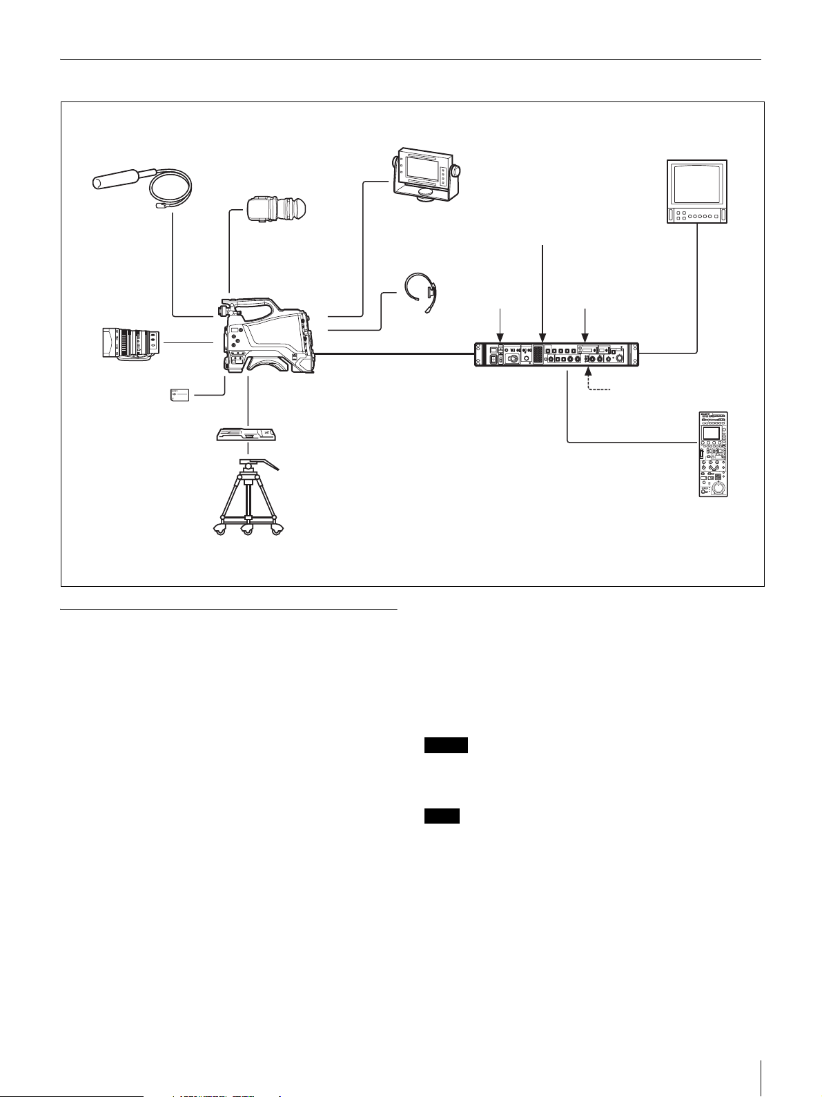
System Configuration Example
Microphone
CBK-VF01
Viewfinder
DXF-20W/C50WA/51
Viewfinder
Picture Monitor
Return Video Input
HXC-D70 HD
Color Camera
Zoom Lens
(for ENG/EFP)
“Memory Stick Duo”
VCT-14/U14
Tripod Adaptor
Tripod for
Portable Camera
1) An equivalent cable length of up to 100 m is approved.
For details, see “Low-loss Digital Transmission via Multi-core Cable” (page 31).
Multi-Core Cable
Intercom Headset
Using the CD-ROM Manual
The supplied CD-ROM includes versions of the operating
instructions for the HXCU-D70 in Japanese, English, French,
German, Italian, Spanish and Chinese in PDF format.
Reading the CD-ROM manual
Prompter Video Input
HD-SDI/SD-SDI/VBS/
HDMI Video Outputs
AC Power
CCA-5 Cable/LAN Cable
RCP-1000-series
Remote Control Panel
1)
HXCU-D70 Camera
Control Unit
Sync Input
1 Insert the CD-ROM in your CD-ROM drive.
A cover page appears automatically in your browser. If it
does not appear automatically in the browser, double click
on the index.htm file on the CD-ROM.
2 Select and click on the operating instructions that you
want to read.
This opens the PDF file of the operating instructions.
Preparations
The following program must be installed on your computer in
order to read the operating instructions contained on the CDROM.
• Adobe Reader Version 6.0 or higher
If Adobe Reader is not installed, you can download it from the
following URL:
http://www.adobe.com/
Adobe and Adobe Reader are trademarks of Adobe Systems
Incorporated in the United States and/or other countries.
To read the documents
To read the operating instructions contained on the CD-ROM,
do the following.
Memo
The files may not be displayed properly, depending on the version of
Acrobat Reader. In such a case, install the latest version you can
download from the URL mentioned in “Preparations” above.
Note
If you have lost or damaged the CD-ROM, you can purchase a new
one to replace it. Contact your Sony dealer or a Sony service
representative.
Overview
7
Page 8
Preparations
Area Settings
Before using the unit
There is no default area setting. Set the area where you intend
to use this unit first.
“- - - - ” appears in the SHUTTER display five seconds after
setting. Area settings are stored and the units switches to
normal mode.
CABLE COMPENSATION Settings
You can set cable compensation according to the multi-core
cable length between the camera and CCU. A built-in cable
compensation circuit compensates for the frequency losses in
the cable. This way, losses in return video and prompter video
inputs are minimized.
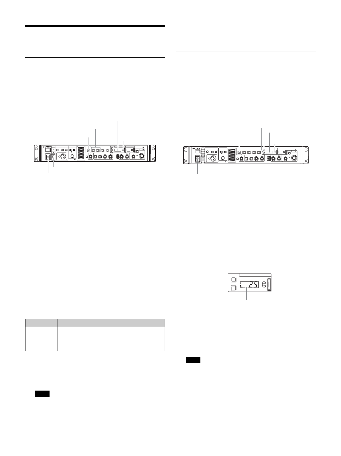
Setting the area
SHUTTER display
SW1, SW2 button
PANEL ACTIVE button
CABLE
INTERCOM
ALARM
OPEN
CAM
POWER
POWER
LOCK
ON
OFF
MENU
MIC-ON
PROD
DISP
CANCEL
OFF
ENG
PGM
MENU ENTER
CONTROL
NETWORK
PANEL
BARS STANDARD
SW1 SW2
ACTIVE
CUSTOM
ATW PRESET
CALL
ECS
ON
WHITE
WHITE
AUTO
BLACK
UP/DOWN lever
MASTER GAINSHUTTER
ALARM
UP
IRIS/MB
AUTO
DOWNUPDOWN
BLACK/FLARE
ACTIVE
IRIS
MASTER BLACK
EXT
HD CAMERA CONTROL UNIT HXCU-D70
LOCK switch
POWER switch
1 Turn the powe r o n .
The camera does not need to be connected to perform
this setting.
2 Set the LOCK switch to OFF and make sure that the
PANEL ACTIVE button is not illuminated.
If the PANEL ACTIVE button lights up, press the button to
turn the light off.
3 Press and hold down the SW1 and SW2 buttons at the
same time for more than two seconds.
The unit switches to setting mode and selectable setting
values appear in the SHUTTER display.
4 Release the buttons after the unit switches to setting
mode.
Setting the CABLE COMPENSATION function
ECS button
PANEL ACTIVE button
CABLE
INTERCOM
ALARM
OPEN
CAM
POWER
POWER
LOCK
ON
OFF
MENU
MIC-ON
PROD
DISP
CANCEL
OFF
ENG
PGM
MENU ENTER
CONTROL
NETWORK
ON button
PANEL
SW1 SW2
ACTIVE
CUSTOM
CALL
ATW PRESET
SHUTTER display
ECS
BARSSTANDARD
ON
WHITE
WHITE
AUTO
BLACK
UP/DOWN lever
MASTER GAINSHUTTER
ALARM
UP
IRIS/MB
AUTO
DOWNUPDOWN
BLACK/FLARE
ACTIVE
IRIS
MASTER BLACK
EXT
HD CAMERA CONTROL UNIT HXCU-D70
LOCK switch
POWER switch
1 Turn the power on.
The camera does not need to be connected to perform
this setting.
2 Set the LOCK switch to OFF and make sure that the
PANEL ACTIVE button is not illuminated.
If the PANEL ACTIVE button lights up, press the button to
turn the light off.
3 Press and hold down the SHUTTER ECS and ON
buttons at the same time for more than two seconds.
The unit switches to setting mode and setting values
appear in the SHUTTER display.
ECS
ON
SHUTTER
UP
DOWN
5 Select the desired area, using the UP/DOWN lever,
within five seconds after the unit switches to setting
mode.
Settings Areas
60i5 NTSC (except Japan)
60i NTSC (Japan)
50i PA L
c)
a) NTSC composite video signal output with a black setup (7.5 IRE).
System frequency: 59.94i
b) NTSC composite video signal output with no black setup. System
frequency: 59.94i
c) PAL composite video signal output. System frequency: 50i
Note
The setting mode is deactivated unless setting starts within five
seconds after the unit switches to setting mode. Follow step 3
again to activate setting mode.
Preparations
8
a)
b)
Displayed numbers indicate cable length (unit: m).
4 Release the buttons after the unit switches to setting
mode.
5 Adjust the setting value according to the cable length,
using the UP/DOWN lever, within five seconds after
the unit switches to setting mode.
Note
The setting mode is deactivated unless setting starts within five
seconds after the unit switches to setting mode. Follow step 3
again to activate setting mode.
“- - - - ” appears in the SHUTTER display five seconds after
setting. Cable compensation settings are stored and the units
switches to normal mode.
Page 9
Locations and Functions of Parts
n
r
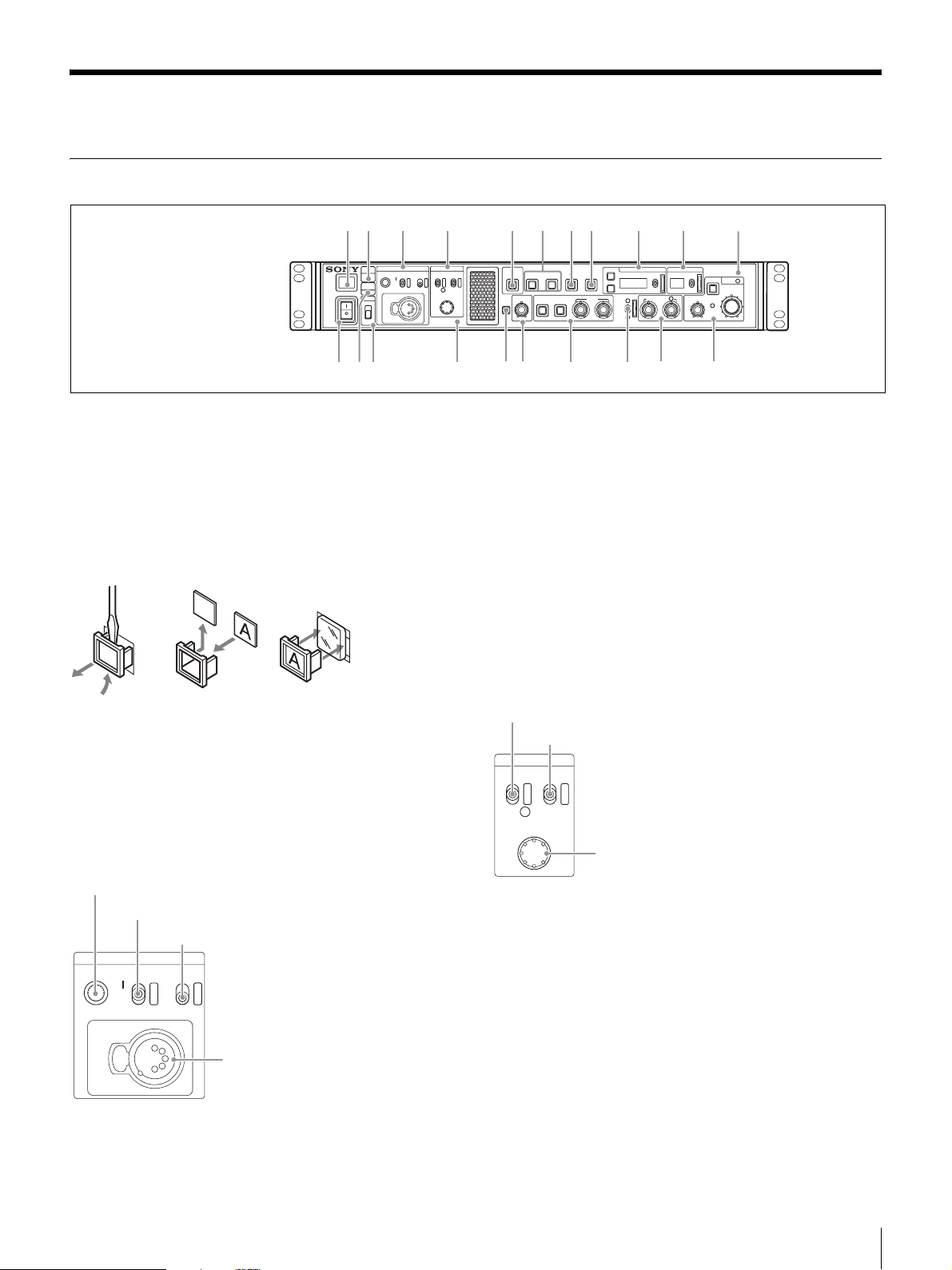
Front Panel
a
POWER
cd
b
CABLE
INTERCOM
ALARM
MIC-ON
OPEN
OFF
CAM
POWER
PGM
LOCK
ON
OFF
MENU
PROD
DISP
ENG
MENU ENTER
CONTROL
NETWORK
lm
a Tally light
Turns on red to indicate a red tally signal is being received
(such as when the picture from the camera connected to the
CCU is being used). When the CALL button on the camera or
the RCP-1000- series Remote Control Panel is pressed, the
light turns off if lit or turns on if not lit.
Turns on green to indicate a green tally signal is being
received.
A number plate supplied with the CCU can be attached here
(see the following figure).
CANCEL
o
p
CALL
e
PANEL
ACTIVE
CUSTOM
q
f
SW1 SW2
ATW PRESET
gh
BARS STANDARD
ECS
ON
WHITE
WHITE
AUTO
BLACK
s
ij
MASTER GAINSHUTTER
UP
DOWNUPDOWN
MASTER BLACK
BLACK/FLARE
HD CAMERA CONTROL UNIT HXCU-D70
t
AUTO
EXT
u
k
ALARM
IRIS/MB
ACTIVE
IRIS
• MIC/PGM (microphone/program) switch
ON: Turns the headset microphone on.
OFF: Turns the headset microphone off.
PGM: Selects program audio output. In this mode, the
INTERCOM knob adjusts the headset program audio level.
• INTERCOM (intercom select) switch
Selects the intercom signal input/output connection source for
the INTERCOM connector on the front panel.
PROD: Connects the producer line.
ENG: Connects the engineer line.
• INTERCOM connector (XLR 5-pin)
Connects the intercom headset.
For information on pin assignment, see “INTERCOM” in “Pin
assignment” on page 33.
d MENU control block
b CABLE ALARM indicators
OPEN: Turns on when a camera is not connected (open
circuit) to the CAMERA connector on the rear panel via a
multi-core cable. While on, the CCU does not supply any
power to the camera.
It flashes when there is a problem with the transmission
between the camera and the CCU.
c INTERCOM audio input/output and control block
INTERCOM (intercom adjustment) knob
MIC/PGM (microphone/program) switch
INTERCOM (intercom select) switch
INTERCOM
MIC-ON
OFF
PGM
PROD
ENG
INTERCOM
connector
• INTERCOM (intercom adjustment) knob
Adjusts the receiver audio level of the intercom.
DISP/MENU (display/menu) lever and indicator
CANCEL/ENTER lever
MENU
DISP CANCEL
MENU ENTER
CONTROL
CONTROL knob
• DISP/MENU (display/menu) lever and indicator
Selects the status display or setup menu display. In setup
menu mode, the indicator turns on.
• CANCEL/ENTER lever
In setup menu mode, used to cancel and enter settings.
• CONTROL knob (rotary encoder)
In status screen mode, used to change the displayed page.
In setup menu mode, used to move the cursor on a page and
to change menu settings. Pressing the CONTROL knob
performs the same function as setting the CANCEL/ENTER
lever to the ENTER position.
Locations and Functions of Parts
9
Page 10
e PANEL ACTIVE button
Activates the control panel to control the camera connected to
the CCU (panel active state). When the button is lit, the
IRIS/MB ACTIVE indicator also turns on simultaneously.
When the button is not lit, the panel is deactivated (panel lock
state) to prevent inadvertent operation.
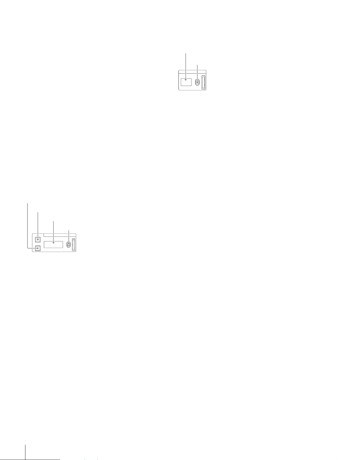
j MASTER GAIN control block
Controls the video output signal gain in response to the
lighting of the subject.
Display
UP/DOWN lever
f SW1, SW2 (assignable switch 1, 2) buttons
Controls the function assigned to each button on the <FRONT
PANEL 1> page in the CCU CONFIGURATION menu. The
button light turns on/off as the assigned function is switched
on/off.
See “ASSIGNABLE/CUSTOM” on <FRONT PANEL 1> on
page 27.
g BARS (color bars) button
Switches on the color bar signal output to the monitor
connected to the CCU (button light turns on). Pressing the
button again restores the previous signal output.
h STANDARD button
Stores the current camera settings as the reference file data
values in the camera (button light turns on for a few seconds).
While the button is lit, pressing the button again cancels the
operation and restores the previous data values.
i SHUTTER control block
Controls the shutter settings.
ON button
ECS (extended clear scan) button
Display
UP/DOWN lever
ECS
ON
SHUTTER
UP
DOWN
• ON button
Switches the normal shutter function or extended clear scan
function on/off (button light turns on/off).
• ECS (extended clear scan) button
Switches the extended clear scan mode on/off (button light
turns on/off).
•Display
When the ECS button is lit: Displays the clear scan frequency.
When the ECS button is not lit: Displays the shutter speed.
• UP/DOWN lever
When the ECS button is lit: Adjusts the clear scan frequency.
UP increases the frequency, and DOWN decreases the
frequency.
When the ECS button is not lit: Adjusts the shutter speed. UP
increases the shutter speed, and DOWN decreases the
shutter speed.
Holding the lever UP or DOWN advances the setting in that
direction.
MASTER GAIN
UP
DOWN
•Display
Displays the video output signal gain setting (dB units).
• UP/DOWN lever
Adjusts the video output signal gain setting (dB units).
UP increases the gain, and DOWN decreases the gain.
Holding the lever UP or DOWN advances the setting in that
direction.
k ALARM indicator
Lights up red to indicate an error in the CCU or camera
system.
l POWER switch
Switches the power for the entire system on and off, including
the CCU, camera, and the RCP-1000-series Remote Control
Panel connected to the REMOTE connector on the rear panel.
Pressing the “?” side turns the camera system on, and
pressing the “a” side turns it off.
m CAM POWER indicator
Turns on when power is supplied to the camera.
n LOCK switch
Locks the buttons on the front panel. Select the desired
buttons to be locked on the <FRONT PANEL 3> page in the
CCU CONFIGURATION menu.
See “(LOCK TARGET)” on <FRONT PANEL 3> on page 29.
o NETWORK indicator
Displays the network system connection status.
On: Indicates that external control equipment (RCP-1000-
series Remote Control Panel or other device) is
connected.
Flashing: Indicates a connection problem with the external
control equipment (RCP-1000-series Remote Control
Panel or other device).
Off: Indicates that a LAN cable is not connected or that the
network system connection parameters have not been set.
See “Network diagnostics” on page 15 and NETWORK
SETTINGS menu on page 29.
p CALL button
Sends a call signal to the camera connected to the CCU and
any external controller (such as the RCP-1000-series Remote
Control Panel).
The CALL button is commonly used to raise the camera
operator or external control equipment operators on the
intercom.
Locations and Functions of Parts
10
Page 11

q CUSTOM (custom volume) knob
Controls the function assigned to the knob on the <FRONT
PANEL 1> page in the CCU CONFIGURATION menu. Turning
the knob adjusts the assigned function.
See “VOLUME” on <FRONT PANEL 1> on page 27 and
“CUSTOM” on <FRONT PANEL 2> on page 28.
r White balance adjustment control block
ATW (auto tracing white balance) button
PRESET (white balance preset) button
WHITE (white balance manual adjustment) knobs
u IRIS/MASTER BLACK adjustment control block
MASTER BLACK (master black adjustment) knob
EXT (lens extender) indicator
AUTO (auto iris) button
IRIS/MB
MASTER BLACK
AUTO
EXT
ACTIVE
IRIS
IRIS/MB ACTIVE (iris/master black
active) indicator
IRIS (iris adjustment) knob
ATW PRESET
WHITE
• ATW (auto tracing white balance) button
The white balance is automatically adjusted in response to the
lighting conditions while this button is turned on and lit.
• PRESET (white balance preset) button
The white balance is automatically adjusted with a 3200K
color temperature preset value while this button is turned on
and lit.
• WHITE (white balance manual adjustment) knobs
Adjusts the white balance manually. The left knob adjusts the
R coefficient, and the right knob adjusts the B coefficient.
The adjustment can be set to relative or absolute value mode
on the <FRONT PANEL 1> page in the CCU
CONFIGURATION menu. The default value is relative value
mode.
See “R/B WHITE” on <FRONT PANEL 1> on page 27 and
“R/B WHITE” on <FRONT PANEL 2> on page 28.
Note
When the ATW button is lit, the WHITE knobs are deactivated.
s AUTO WHITE/BLACK (white balance/black balance
auto adjustment) lever
Initiates the white balance or black balance auto adjustment
function.
WHITE automatically adjusts the white balance, and BLACK
automatically adjusts the black balance.
t BLACK/FLARE (black balance/flare balance manual
adjustment) knobs and indicator
Adjusts the black balance and flare balance manually. When
the indicator is not lit, the knobs adjust the black balance.
When the indicator is lit, the knobs adjust the flare balance.
The left knob adjusts the R coefficient, and the right knob
adjusts the B coefficient.
The indicator operating mode (on/off function) can be set on
the <FRONT PANEL 1> page in the CCU CONFIGURATION
menu.
The adjustment can be set to black balance or flare balance
adjustment in relative or absolute value mode on the <FRONT
PANEL 1> page in the CCU CONFIGURATION menu. The
default value is black balance adjustment in relative value
mode.
See “R/B BLACK” on <FRONT PANEL 1> on page 27 and
“R/B BLACK” on <FRONT PANEL 2> on page 28.
• MASTER BLACK (master black adjustment) knob
Adjusts the master black manually.
The adjustment can be set to relative or absolute value mode
on the <FRONT PANEL 1> page in the CCU
CONFIGURATION menu. The default value is relative value
mode.
See “M BLACK” on <FRONT PANEL 1> on page 27 and
“M BLACK” on <FRONT PANEL 2> on page 28.
• EXT (lens extender) indicator
Turns on to indicate that the lens extender is in-use on the
camera.
• AUTO (auto iris) button
Switches the lens auto iris adjustment function on/off (button
light turns on/off). The iris is automatically adjusted in
response to the input light level.
When the button is not lit, the iris is adjusted manually.
• IRIS/MB ACTIVE (iris/master black active) indicator
Indicates, when lit, that the iris and master black controls are
active (in panel active state set by the PANEL ACTIVE button).
When the indicator is lit, the iris and master black can be
adjusted from the CCU.
Note
The indicator is not lit when the iris and master black controls in the
RCP-1000-series Remote Control Panel are active.
• IRIS (iris adjustment) knob
When the AUTO button is not lit: Adjusts the lens iris manually.
When the AUTO button is lit: Finely adjusts the auto adjusted
iris value.
The adjustment can be set to relative or absolute value mode
on the <FRONT PANEL 1> page in the CCU
CONFIGURATION menu. The default value is absolute value
mode.
See “IRIS” on <FRONT PANEL 1> on page 27 and “IRIS” on
<FRONT PANEL 2> on page 28.
Locations and Functions of Parts
11
Page 12

Rear Panel
a
PRO
REFERENCE PROMPTER
IN IN
OUT OUT
b
d
c
S-VIDEO
OUTPUT
SDI OUTPUT
HDMI
1234
OUTPUT
e
VBS RETURN
Pb/B/B-YY/G/YPr/R/R-YREMOTE
1
SYNCPIXVBS2VBS1
2
IN IN
OUT OUT
INTERCOM/TALLY/PGM
f
AUDIO OUTPUT
CH-1
g
CH-2
CAMERA
TRUNK
h
~ AC IN
n
i
j
k
l
m
o
p
a “Memory Stick” slot
For service use only.
b LAN jack (RJ-45, 8-pin)
Connects to a LAN hub (10BASE-T/100BASE-TX), when
using a network connection, via a LAN cable (shielded type,
category 5 or higher).
CAUTION
• For safety, do not connect the connector for peripheral device wiring
that might have excessive voltage to this port. Follow the
instructions for this port.
• When you connect the LAN cable of the unit to peripheral device,
use a shielded-type cable to prevent malfunction due to radiation
noise.
ATTENTION
Par mesure de sécurité, ne raccordez pas le connecteur pour le
câblage de périphériques pouvant avoir une tension excessive à ce
port. Suivez les instructions pour ce port.
VORSICHT
Aus Sicherheitsgründen nicht mit einem Peripheriegerät-Anschluss
verbinden, der zu starke Spannung für diese Buchse haben könnte.
Folgen Sie den Anweisungen für diese Buchse.
c REMOTE connector (8-pin)
Transmits and receives control signals from the RCP-1000series Remote Control Panel via a CCA-5 cable (optional). It
also supplies power when connected to an RCP-1000-series
Remote Control Panel.
d Pr/R/R-Y, Y/G/Y, Pb/B/B-Y (component signals)
connectors (BNC type)
Outputs the HD component signals, SD component signals,
HD RGB signals, or SD RGB signals from the corresponding
connectors.
e VBS RETURN 1, 2 (VBS return video 1, 2) connectors
(BNC type)
IN: Inputs the VBS return video signals (2-system).
OUT: The input signal is output from the other connector as-is
(loop-through output). If the loop-through output is not
used, it is automatically connected to a 75 Ω terminator.
f AUDIO OUTPUT CH-1, CH-2 connectors (XLR 3-pin)
Outputs audio signals from the camera AUDIO 1 IN and
AUDIO 2 IN connectors.
q
r
g CAMERA connector (multi-core connector)
Connects to the camera via a multi-core cable. The camera
sends all video and audio signals to the CCU, and the CCU
sends control signals, return video, audio signals and power to
the camera over a single multi-core cable.
CAUTION
CAMERA connector is non LPS (Limited Power Source) circuit. This
connector is connected to the HXC-D70.
h AC supply input connector
Connects to the AC supply via the specified power cord
(optional). A plug holder (optional) can be used to secure the
power cord to the CCU.
i REFERENCE (reference input) connectors (BNC type)
IN: Inputs an HD tri-level reference sync signal or SD
reference sync signal (black burst signal) for external sync.
OUT: The input signal is output from the other connector as-is
(loop-through output). If the loop-through output is not
used, it is automatically connected to a 75 Ω terminator.
j PROMPTER (teleprompter input) connectors
(BNC type)
IN: Inputs the VBS signal for the teleprompter.
OUT: The input signal is output from the other connector as-is
(loop-through output). If the loop-through output is not
used, it is automatically connected to a 75 Ω terminator.
k S-VIDEO OUTPUT connector (4-pin)
Outputs S-VIDEO signal.
l HDMI OUTPUT connector (19-pin)
Outputs HDMI signal for a video monitor compatible with HDMI
input.
Notes
• When connecting a household television with HDMI input, set its
high-resolution function to off to avoid image artifacts.
• Use a Sony high-speed HDMI cable.
m VBS 1, 2 (composite video signal 1, 2) connectors
(BNC type)
Outputs (2-system) the camera signals in composite signal
format.
n SDI OUTPUT 1 to 4 connectors (BNC type)
Outputs the camera signals in HD SDI or SD SDI signal
format.
The SDI OUTPUT 3 and SDI OUTPUT 4 connectors can also
output signals with superimposed character or marker display.
Locations and Functions of Parts
12
Page 13

o PIX (picture monitor output) connector (BNC type)
Outputs a video signal for a picture monitor. It can also output
a signal with superimposed character display.
p SYNC (sync signal output) connector
Outputs a sync signal for connection to the sync signal input
connector of a waveform monitor or picture monitor.
q INTERCOM/TALLY/PGM (intercom/tally/program
audio) connector (D-sub 25-pin)
Transmits and receives the various intercom, tally, and
program audio signals. It connects to the intercom/tally/
program audio connector of the intercom system.
For information on pin assignment, see
“INTERCOM/TALLY/PGM” in “Pin assignment” on page 33.
Note
Depending on the PGM MIX LEVEL settings of the camera, PGM
signal may leak into the INTERCOM output. Turn the PGM MIX
LEVEL settings down to reduce the signal interference.
r TRUNK connector (D-sub 9-pin, RS-232C standard)
Connects to an external device to provide a communication
path via the CCU between that device and another external
device connected to the TRUNK connector on the camera.
For information on pin assignment, see “TRUNK” in “Pin
assignment” on page 34.
Locations and Functions of Parts
13
Page 14

Camera settings
Status Display
The CCU system status can be monitored using a picture
monitor connected to the PIX output.
For information on monitoring and changing settings, see
“Setup Menu” on page 17.
Displaying the Status Screen
The status screen is controlled using the knob and levers in
the MENU control block on the front panel.
DISP/MENU lever and indicator
MENU
DISP CANCEL
MENU ENTER
CONTROL
CONTROL knob
To display the status screen
Set the DISP/MENU lever to the DISP position.
The most recently viewed status screen page is displayed
(when first powered on, the camera settings page is
displayed).
Turning the CONTROL knob changes the displayed page.
To exit the status screen display
In status screen display mode, set the DISP/MENU lever to the
DISP position.
Status Display Screen
Page 1
a
6dB 1/2000 OFF
ND:1 F:4.7 EX
b
cd
efg
a Master gain value
Video output signal gain (dB units)
b Shutter speed/Clear scan frequency
Shutter speed value. When ECS is on, the clear scan
frequency is displayed.
c Shutter/ECS
Shutter/ECS on/off indicator
d Camera auto control information area
Top : Displays the Auto Setup category and execution status
Bottom: Displays the execution item
e ND filter
Current ND filter selection
f F-stop value
Lens F-stop value (iris value)
g EX (lens extender)
Lens extender indicator
Notes
• Items that are turned off using the <DISPLAY> page settings of the
CCU CONFIGURATION menu are not displayed.
• A “-” mark is displayed for each item when a camera is not
connected.
The following information is displayed on the status display
screen.
• Camera settings
•System status
• CCU hardware diagnostics
• Camera system diagnostics
• Network diagnostics
• CCU AT board diagnostics
• CCU DPR board diagnostics
• Front panel diagnostics
• Camera hardware diagnostics
• ROM version information for major components
Status Display
14
Page 2
6dB 1/2000 OFF
White Black
R: 0 R: 0
G: 0 G: 0
B: 0 B: 0
M: 0
BLK γ Flare
: 0 R: 0
DTL G: 0
: 0 B: 0
ND:1 F:4.7 EX
White: White balance R/G/B value
Black: Black balance R/G/B/Master value
BLK γ: Black gamma value
Flare: Flare balance R/G/B value
DTL: Detail level
Note
The items along the bottom edge are common to both pages 1 and 2.
Page 15

System status
*System Status* 1/13
HXC-D70 1080/59.94I
Reference:Free Lock
SDI-1/2 :1080/59.94I
SDI-3/4 :525/59.94I
Component:SD YCD
Page 2
*System Diag 2/3* 4/13
CAMERA Cable Connect
Data OK
Power OK
REMOTE Cable Connect
Data OK
Power OK
The camera model name and signal format are displayed at
the top of the page (a “-” mark is displayed instead when a
camera is not connected).
Reference: Reference signal format and lock status
SDI-1/2: SDI OUTPUT 1/2 connector output format setting
SDI-3/4: SDI OUTPUT 3/4 connector output format setting
Component: Component signal connector output format
setting
CCU hardware diagnostics
*Diagnosis* 2/13
DPR :OK
AT :OK
Front Panel : OK
The camera Auto Setup category, and the corresponding
setup item and status are displayed at the top of the page.
DPR: DPR board status
AT: AT board status
Front Panel: Front panel status
CAMERA Cable: Camera cable connection status
CAMERA Data: Camera data transmission status
CAMERA Power: Camera power supply status
REMOTE Cable: Remote device cable connection status
REMOTE Data: Remote device data transmission status
REMOTE Power: Remote device power supply status
Page 3
*System Diag 3/3* 5/13
Intercom
CCU FRONT PROD
MIC ON
CAMERA ENG+PROD
MIC OFF
CAM MIC Gain
CH1(FRONT) 60
CH2(REAR) 60
Intercom CCU FRONT: CCU intercom selection
Intercom CAMERA: Camera intercom channel 1 selection
and microphone status
CAM MIC Gain CH1 (FRONT): Amplifier gain for a
microphone connected to the camera AUDIO 1 IN
connector.
CAM MIC Gain CH2 (REAR): Amplifier gain for a microphone
connected to the camera AUDIO 2 IN connector.
dB
dB
Camera system diagnostics
Page 1
Multi Type: Multi-core cable transmission mode
Multi Cable: CCU multi-core cable connection status
Multi Comp.: Multi-core cable compensation mode selection
Multi Step: Multi-core cable length display
Fan Power: CCU power supply fan status
Timer: Elapsed time since power-on
CCU Power: CCU power supply status
SerialNo: CCU serial number
Network diagnostics
Page 1
*Network Diag 1/3* 6/13
MacAddress:000000-000000
Auto Negotiation: ON
Connection Speed:100M
Duplex Mode :HALF
Link Status :OK
MacAddress: MAC address stored in CCU EEPROM
Auto Negotiation: Auto negotiation setting
Connection Speed: Connection speed setting
Duplex Mode: Communication method setting
Link Status: Network connection status
Status Display
15
Page 16

Page 2
*Network Diag 2/3* 7/13
CNS Mode :BRIGDE
CCU No. :1
CNS Mode: REMOTE and LAN connectors mode setting
CCU No.: CCU number setting
Page 3
*Network Diag 3/3* 8/13
IP Address
0. 0. 0. 0
Subnet Mask
0. 0. 0. 0
Default Gateway
0. 0. 0. 0
IP Address: CCU IP address setting
Subnet Mask: CCU subnet mask setting
Default Gateway: CCU default gateway setting
PLD DE-MUX: DEMUX-PLD version
PLD SY: SY-PLD version
PLD POST: POST-PLD version
PLD HDMI: HDMI-PLD version
IIC: IIC bus control status
DPR POWER: DPR board power supply status
Front panel diagnostics
*Front Panel Diag* 11/13
Assignable/Custom
SW1 :CAM POWER
SW2 :5600K
VOLUME :SD DTL Level
SW Bright:Normal
IIC :OK
Assignable/Custom SW1: Function assigned to the SW1
button
Assignable/Custom SW2: Function assigned to the SW2
button
Assignable/Custom VOLUME: Function assigned to the
CUSTOM knob
SW Bright: Button lights LED brightness setting
IIC: IIC bus control status
Camera hardware diagnostics
CCU AT board diagnostics
*AT Diag* 9/13
Reference :HD
PLD Status :OK
AT :1.00
AT POWER:OK
Reference: Reference signal setting
PLD Status: PLD status
PLD AT: AT-PLD version
AT POW ER : AT board power supply status
CCU DPR board diagnostics
*DPR Diag* 10/13
HD CB :BAR 16:9(100%)
SD CB :SMPTE
HDMI Firmware:1.00
PLD Status:OK
DE-MUX:1.00
SY :1.00
POST :1.00
HDMI :1.00
IIC :OK
DPR POWER:OK
*CAMERA Diag* 12/13
ALL BOARD OK
Displays the camera hardware status.
ROM Version Information
*ROM Version* 13/13
CAMERA HXC-D70
1.00 11.08.01
CCU HXCU-D70
1.00 11.08.01
CAMERA: Camera model name and ROM version
CCU: CCU model name and ROM version
HD CB: HD color bar setting
SD CB: SD color bar setting
HDMI Firmware: HDMI firmware version
PLD Status: PLD status
Status Display
16
Page 17

To change the displayed page
Setup Menu
The CCU system and peripheral settings can be checked and
modified using a picture monitor connected to the PIX output.
Changing Menu Item Settings
The menu screen is controlled using the knob and levers in the
MENU control block on the front panel.
Setting the CANCEL/ENTER lever to the ENTER position and
pressing the CONTROL knob perform the same function.
DISP/MENU lever and indicator
CANCEL/ENTER lever
MENU
DISP CANCEL
MENU ENTER
CONTROL
CONTROL knob
To display a menu page
Set the DISP/MENU lever to the MENU position.
When first powered on, the CCU MENU page is displayed.
To display the CCU MENU page
In menu display mode, turn the CONTROL knob to move the
pointer (,) to TOP in the upper right corner of the menu page,
then press the CONTROL knob.
The CCU MENU showing the menu configuration is displayed.
** CCU MENU **
c SYSTEM OPERATION
CCU CONFIGURATION
NETWORK SETTINGS
1 Turn the CONTROL knob to move the pointer (,) to
the page number, then press the CONTROL knob.
The pointer (,) changes to a flashing question mark (?).
Flashing
<OUTPUT SELECT> ?S01 TOP
OUTPUT:*CAMERA
BAR
TEST1
TEST2
PIX:*ENC R G B
R&B G&B R&B RGB
2 Turn the CONTROL knob to change the displayed
page to the desired page, then press the CONTROL
knob.
The question mark (?) changes back to the pointer (,).
Items on the page can now be selected and changed.
To change a menu item setting
If a question mark (?) is displayed beside the page number,
press the CONTROL knob to restore the pointer (,). Items
on the page can now be selected and changed.
1 Turn the CONTROL knob to move the pointer (,) to
the desired item, then press the CONTROL knob.
The pointer (,) changes to a flashing question mark (?).
2 Turn the CONTROL knob to change the setting.
To cancel a changed setting
Set the CANCEL/ENTER lever to the CANCEL position
before pressing the CONTROL knob. The item is restored
to its current setting.
To suspend menu changes
Set the DISP/MENU lever to the MENU position to exit the
menu screen.
The DISP/MENU lever can be set to the MENU position
again to restart the operation.
Menu name Description
SYSTEM OPERATION Input/output signal format and
system-related settings
CCU CONFIGURATION CCU configuration settings
NETWORK SETTINGS Network-related settings
To select an item in the CCU MENU
Turn the CONTROL knob to move the pointer (,) up/down to
the desired menu item, then press the CONTROL knob.
The most recently viewed page in the selected menu is
displayed.
3 Press the CONTROL knob.
The question mark (?) changes back to the pointer (,),
and the item setting is registered.
4 Repeat steps 1 to 3 to change other settings on the
same page.
Setup Menu
17
Page 18

To enter a character string
Some menu items require a character string input.
Moving the pointer (,) to an item with a character string input
and pressing the CONTROL knob displays a rectangular
cursor and a list of selectable characters. Turning the
CONTROL knob moves the cursor between characters.
The following menu item has character strings:
• CCU CONFIGURATION menu → <BAR CHARACTER>
page → BAR CHARACTER
1 Move the text cursor to the input position, then press
the CONTROL knob.
A second cursor is displayed in the character list.
2 Turn the CONTROL knob to move the cursor to the
desired character, then press the CONTROL knob.
Repeat steps 1 and 2 to enter other characters.
• Select INS to insert a space character at the cursor
position.
• Select DEL to delete the character at the cursor
position.
• Select RET to return to step 1 without changing the
string.
• Entering the maximum number of characters (up to the
right edge) moves the cursor to ESC on the lower right
of the character list.
3 Turn the CONTROL knob to move the cursor to END,
then press the CONTROL knob.
The new input string is registered.
To cancel the character string setting
Turn the CONTROL knob to move the cursor to ESC, then
press the CONTROL knob.
To exit the menu display
In menu display mode, set the DISP/MENU lever to the MENU
position.
18
Setup Menu
Page 19

Menu Tree
SYSTEM OPERATION menu CCU CONFIGURATION menu
OUTPUT SELECT OUTPUT
PIX
GENLOCK PHASE REFERENCE
GENLOCK
H STEP
COARSE
SC PHASE
V PHASE
SYNC OUT
MULTI FORMAT FREQUENCY
CAMERA FORMAT
OUTPUT FORMAT SLOT NO
3&4
COMPONENT
SD ASPECT SD ASPECT
SD LB SEL
H POSITION
CENTER
V POSITION
CENTER
H INTERP
1- 1&2
HDMI
V INTERP
COLOR BAR HD BAR
SEL
MF CB
SLOPE
SD BAR
BAR CHARA
GRAY
BAR CHARACTER BAR CHARACATER
ALL CLEAR
MONITOR 1 CHARACTER
WHITE LEVEL
BLACK LEVEL
PIX CHARACTER
WHITE LEVEL
BLACK LEVEL
MONITOR 2 LEVEL GATE
MIC/AUDIO CAM MIC GAIN
CH1
CH2
AUDIO OUTPUT
CH2 LEVEL
INTERCOM SYSTEM I/F
TERMINATION
FRONT INCOM
VIDEO SETUP
Q FILTER
SD G/Y SYNC
VIDEO ADJUST VBS
LEVEL
CHROMA
PIX
LEVEL
CHROMA
S-VIDEO LEVEL
COMPONENT LEVEL
MENU SETTINGS RESUME
RE DIRECTION
CATEGORY
PAGE
ITEM
DATA
Y LEVEL1
Y LEVEL2
GATE MARKER
MODULATION
MARKER
CH1 LEVEL
PGM INPUT
INCOM MIC
SIDE TONE
PGM MIX
PGM LEVEL
SETUP
MIC TYPE
MIC GAIN
Setup Menu
19
Page 20

DISPLAY MESSAGE
ALARM JUMP
MASTER GAIN
ECS/SHUTTER
ND FILTER
IRIS
EXTENDER
DATE DATE/TIME
TIME ZONE
OTHERS REAR PREVIEW
FRONT PANEL 1 ASSIGNABLE/CUSTOM
SW1
SW2
VOLUME
VOLUME MODE
IRIS
M BLACK
R/B BLACK
R/B WHITE
FRONT PANEL 2 VOLUME REL COEFF
IRIS
M BLACK
R/B BLACK
R/B WHITE
CUSTOM
SW BRIGHT
FRONT PANEL 3 LOCK TARGET
CABLE COMP
NETWORK SETTINGS menu
TCP/IP SETTING IP ADDRESS
SUBNET MASK
DEFAULT GATEWAY
SET
LAN SETTINGS AUTO NEGOTIATION
CONNECTION SPEED
DUPLEX MODE
LINK CONDITION
CNS SETTINGS CNS MODE
NETWORK RESET ALL RESET
SET
CCU NO
20
Setup Menu
Page 21

Menu List
Note
The following conventions are used in the menu list table.
Settings column values (e.g. ON
Execute by ENTER: Press the CONTROL knob or move the CANCEL/ENTER lever to the ENTER position to execute.
SYSTEM OPERATION menu
SYSTEM OPERATION
Page name
Page No.
<OUTPUT SELECT>
S01
<GENLOCK PHASE>
S02
<MULTI FORMAT>
S03
Note
FREQUENCY or
CAMERA FORMAT mode
setting changes take
effect only after the CCU
power supply is turned off
and then on again.
, OFF, 0): Default settings
Item Settings Description
OUTPUT CAMERA
PIX ENC
REFERENCE (NONE), (EXT IN) Reference signal input status (display only)
GENLOCK (HD), (SD
H STEP When GENLOCK mode is HD:
COARSE –99.9 to 99.9 0.0
SC PHASE 0
V PHASE 0
SYNC OUT HD SYNC, SD SYNC
FREQUENCY 59.94 Hz
CAMERA FORMAT When FREQUENCY is set to
RGB
(OK), (NG) External reference signal lock status
External reference signal format Displayed only when a reference signal is
–3.01 to 3.45 µs 0.00
When GENLOCK mode is SD:
–8.29 to 9.48 µs 0.00
to 359 Subcarrier phase
to 7 Vertical phase (line)
(525 NTSC)
59.94 Hz: 1080/59.94i
When FREQUENCY is set to
50 Hz: 1080/50i, 720/50P
, BAR, TEST1, TEST2 Output signal selection
TEST1 and TEST2 are not selectable if there
is no communication with the camera.
, R, G, B, R&G, G&B, R&B,
) CCU GENLOCK mode, lock status, and signal
, 50 Hz
, (625 PAL)
, 720/59.94P
PIX connector output signal selection
format
(HD): HD
(SD): SD
(OK): Locked
(NG): Unlocked
present.
Reference signal lock phase adjustments
Horizontal phase (STEP)
Horizontal phase
SYNC connector output signal selection
Operating frequency selection
Transmission format selection
Setup Menu
21
Page 22

SYSTEM OPERATION
Page name
Page No.
<OUTPUT FORMAT>
S04
<SD ASPECT>
S05
Item Settings Description
SLOT NO
1-1&2 When CAMERA FORMAT is
3&4 When CAMERA FORMAT is
HDMI HDMI connector output format selection
COMPONENT HD RGB, HD YPbPr, SD RGB,
SD ASPECT SQUEEZE, EDGE CROP
SD LB SEL 16:9
H POSITION –99 to 99, (–99) to (99) 0
CENTER ON
V POSITION –99 to 99, (–99) to (99) (0)
CENTER ON, OFF, (ON)
H INTERP A
V INTERP A
1080/59.94i: 1080/59.94i
525/59.94i
When CAMERA FORMAT is
720/59.94P: 720/59.94P,
525/59.94i
When CAMERA FORMAT is
1080/50i: 1080/50i, 625/50i
When CAMERA FORMAT is
720/50P: 720/50P, 625/50i
1080/59.94i: M1080/59.94i,
M525/59.94i
When CAMERA FORMAT is
720/59.94P: M720/59.94P,
M525/59.94i
When CAMERA FORMAT is
1080/50i: M1080/50i, M625/50i
When CAMERA FORMAT is
720/50P: M720/50P, M625/50i
SD YCD
BOX
, 15:9, 14:9, 13:9 LETTER BOX aspect ratio selection
, OFF, (ON), (OFF) Horizontal centering selection
, (OFF) Vertical centering selection
, B, C, D, E Down converter horizontal filter selection
, B, C, D, E Down converter vertical filter selection
,
, LETTER
SDI OUTPUT 1/2 connector output format
selection
Sequence of format options:
1: HD
2: SD
SDI OUTPUT 3/4 connector output format
selection
Sequence of format options:
1: HD
2: SD
(display only)
Component signal connector output format
selection
SD output aspect selection
Horizontal position setting
Settings in ( ): Displayed when SQUEEZE or
LETTER BOX is selected in SD ASPECT
(display only)
Settings in ( ): Displayed when SQUEEZE or
LETTER BOX is selected in SD ASPECT
(display only)
Vertical position setting
Settings in ( ): Displayed when SQUEEZE or
EDGE CROP is selected in SD ASPECT
(display only)
Settings in ( ): Displayed when SQUEEZE or
EDGE CROP is selected in SD ASPECT
(display only)
22
Setup Menu
Page 23

CCU CONFIGURATION menu
CCU CONFIGURATION
Page name
Page No.
<COLOR BAR>
C01
<BAR CHARACTER>
C02
<MONITOR 1>
C03
Item Settings Description
HD BAR
SEL BAR 16:9 (100%)
MF CB MODIFY
SLOPE WIDE
SD BAR For NTSC: SMPTE
BAR CHARA ON, OFF
GRAY ON
BAR CHARACTER Settings for strings 1 to 12 that are
<ALL CLEAR> Execute to clear all character strings
CHARACTER Bar character settings
WHITE LEVEL 0.0 to 107.0% 71.5
BLACK LEVEL 0.0
PIX CHARACTER PIX output character settings
WHITE LEVEL 75.0
BLACK LEVEL 0.0
(75%), SMPTE 16:9 (BLACK),
SMPTE 16:9 (–I/Q), BAR 4:3
(100%), BAR 4:3 (75%), SMPTE
4:3 (BLACK), SMPTE 4:3 (–I/Q),
MF-ARIB (75%), MF-ARIB (100%),
MF-ARIB (+I), MF-SMPTE (–I,Q),
MF-SMPTE (75%,Q), MF-SMPTE
(100%,Q), MF-SMPTE (+I,Q),
HD-CUSTOM, SDI CHECK FIELD,
Y-RAMP, Y/C-RAMP,
HD-CUSTOM2
, EVEN Multi-format color bar settings
, NARROW Chroma band settings for color bars
95%, NTSC100%, Y/C-RAMP,
Y- R AM P
For PAL: SMPTE
PAL100%, Y/C-RAMP, Y-RAMP
, OFF ON: Gray screen output when camera power
to 107.0% Black (font border color) level settings for bar
to 107.0% White level settings for PIX output character
to 25.0% Black (font border color) level settings for PIX
, BAR 16:9
, EIA, FULL,
, EIA, EBU, 95%,
HD output color bar settings
SD output color bar setting
Character superimposed on color bar signal
supply is off
OFF: Color bar signal output when camera
power supply is off
superimposed on the color bar signal
(Execute by ENTER)
White level settings for bar character strings
character strings
strings
output character strings
Setup Menu
23
Page 24

CCU CONFIGURATION
Page name
Page No.
<MONITOR 2>
C04
<MIC/AUDIO>
C05
<INTERCOM>
C06
Item Settings Description
LEVEL GATE ---, 1&2, 1, 2, OFF 1&2: Displays level gate 1&2
1: Displays level gate 1
2: Displays level gate 2
---: Displayed when camera not connected,
video output not set to CAMERA, or video
output is set to CAMERA and GATE MARKER
is ON (display only)
Y LEVEL1 0 to 108% 49
–99 to 99 –25
Y LEVEL2 0 to 108% 74
–99 to 99 –25
GATE MARKER ---, ON, OFF
–99 to 99 0
MODULATION ---, ON, OFF
–99 to 99 0
MARKER ON, OFF
4:3
, 13:9, 14:9, EU VISTA, VISTA,
CINEMA, FOLLOW DC
CAM MIC GAIN Microphone gain settings
CH1 ---, 20, 30, 40, 50, 60
CH2 ---, 20, 30, 40, 50, 60
AUDIO OUTPUT Audio output level settings
CH1 LEVEL –20, 0
CH2 LEVEL –20, 0
SYSTEM I/F 4WIRE
TERMINATION (OFF
PGM INPUT –20, 0
61 Level gate 1 minimum and maximum detection
108 Level gate 2 minimum and maximum detection
Mask video level settings
dB Settings vary depending on microphones
dB
, +4 dBu CH1 output level settings
, +4 dBu CH2 output level settings
, RTS, CLEAR COM Intercom interface (D-sub 25-pin) settings
), ON, OFF Connects to a 200 Ω terminator, if ON is
, +4 dBu PGM input level settings
levels settings
Level gate 1 zebra range settings
levels settings
Level gate 2 zebra range settings
Gate signal display on/off settings
---: Displayed when camera not connected
(display only)
Gate signal level settings
4:3 aspect ratio mask function on/off settings
when EDGE CROP is ON
---: Displayed when camera not connected
(display only)
Marker signal on/off settings
Superimposed marker signal selection
---: Displayed when camera not connected
(display only)
selected while 2-wire intercom interface (RTS
or CLEAR COM) is used
(OFF): Displayed when 4WIRE is selected in
SYSTEM I/F (display only)
24
Setup Menu
Page 25

CCU CONFIGURATION
Page name
Page No.
<FRONT INCOM>
C07
<VIDEO SETUP>
C08
<VIDEO ADJUST>
C09
Item Settings Description
(MIC ON), (MIC OFF), (PGM ON) CCU front panel MIC/PGM switch position
(PROD), (ENG) CCU front panel INTERCOM switch position
INCOM MIC CARBON, ECM, DYNAMIC
MIC TYPE BALANCE, UNBALANCE
MIC GAIN –6dB, 0dB
SIDE TONE 0 to 99 50
PGM MIX OFF
L-INCOM/R-PGM
PGM LEVEL 0 to 99 50
SETUP ON, OFF
Q FILTER NARROW
SD G/Y SYNC ON
VBS VBS output settings
LEVEL –99 to 99 0
CHROMA –99 to 99 0
PIX PIX output settings
LEVEL –99 to 99 0
CHROMA –99 to 99 0
S-VIDEO LEVEL –99 to 99 0
COMPONENT LEVEL –99 to 99 0
, +6dB Input gain setting
, INCOM+PGM,
, -- ON: Adds a setup signal to VBS and SD YCD
, WIDE, -- Q FILTER bandwidth setting
, OFF SD RGB component signal Gch-SYNC or SD
(display only)
(display only)
Headset microphone type connected to
INTERCOM on the front panel
CARBON: Carbon microphone (power supply,
20 dB gain)
ECM: Electret condenser microphone (power
supply, 40 dB gain)
DYN AMIC: Dynamic microphone (no power
supply, 60 dB gain)
Headset microphone type connected to
INTERCOM on the front panel
BALANCE: Balanced microphone
UNBALANCE: Unbalanced microphone
Side tone level settings
OFF: Signals are not mixed.
INCOM+PGM: INCOM and PGM signals are
mixed.
L-INCOM/R-PGM: Outputs an INCOM signal
through the left channel and a PGM signal
through the right
PGM level settings
component signal Ych-SYNC
OFF: No setup signal is added.
--: Displayed when format is PAL (display only)
--: Displayed when format is PAL (display only)
YCD component signal Ych-SYNC on/off
VBS output level settings
Chroma settings for VBS output
PIX output level settings
Chroma settings for PIX output
S-VIDEO signal level settings
Component signal level settings
Setup Menu
25
Page 26

CCU CONFIGURATION
Page name
Page No.
<MENU SETTINGS>
C10
<DISPLAY>
C11
Camera messages and
switch settings on/off.
Displayed on the camera
diagnostics screen.
<DATE>
C12
<OTHERS>
C13
Item Settings Description
RESUME ON, OFF In menu mode, resume display of previously
RE DIRECTION CONTROL knob operating mode settings
CATEGORY STD
PAG E STD
ITEM STD
DATA STD
MESSAGE ALL
ALARM JUMP ON, OFF
MASTER GAIN ON
ECS/SHUTTER ON
ND FILTER ON
IRIS ON
EXTENDER ON
DATE/TIME 20YY/MM/DD hh:mm
TIME ZONE hh:mm
REAR PREVIEW MOMENTARY
CABLE COMP 25m
, RVS STD: CONTROL knob clockwise rotation
, RVS STD: CONTROL knob clockwise rotation
, RVS STD: CONTROL knob clockwise rotation
, RVS STD: CONTROL knob clockwise rotation
, WARNING, OFF ALL: Displays all messages
, OFF Displays or hides the master gain indication
, OFF Displays or hides the ECS/shutter indication
, OFF Displays or hides the ND filter indication
, OFF Displays or hides the IRIS indication
, OFF Displays or hides the EXTENDER indication
Time displayed in 24-hour
format
−11h59m to +11h59m
, TOGGLE REMOTE device preview operation switching
, 50m, 75m, 100m Cable compensation settings for frequency
displayed page function
moves the CCU MENU pointer (,) down
RVS: CONTROL knob counterclockwise
rotation moves the CCU MENU pointer (,)
down
displays the next page in the menu
RVS: CONTROL knob counterclockwise
rotation displays the next page in the menu
moves the pointer (,) down to the next item
on the page
RVS: CONTROL knob counterclockwise
rotation moves the pointer (,) down to the
next item on the page
selects the next data option
RVS: CONTROL knob counterclockwise
rotation selects the next data option
WARNING: Displays system warning
messages and menu control messages
OFF: Displays only menu control messages
In menu mode, jump to display page if an error
occurs function
Date and time settings
Time zone setting
MOMENTARY: Display preview while
PREVIEW button on REMOTE device is
pressed
TOGGLE: Toggle preview on/off when the
PREVIEW button on REMOTE device is
pressed
losses in return video and prompter video
inputs
26
Setup Menu
Page 27

CCU CONFIGURATION
Page name
Page No.
<FRONT PANEL 1>
C14
Item Settings Description
ASSIGNABLE/CUSTOM
SW1 NOT ASSIGN
DTL OFF, SD DTL OFF, BLK
GAMMA, KNEE OFF, AUTO
KNEE, 5600K, CAM POWER
SW2 NOT ASSIGN
DTL OFF, SD DTL OFF, BLK
GAMMA, KNEE OFF, AUTO
KNEE, 5600K, CAM POWER
VOLUME NOT ASSIGN
GAMMA, HD DTL LEVEL, SD DTL
LEVEL, BLK GAMMA
VOLUME MODE
IRIS REL, ABS
M BLACK REL
R/B BLACK REL/BLACK
REL/FLARE, ABS/FLARE
R/B WHITE REL
, GAMMA OFF, HD
, GAMMA OFF, HD
, HD GAMMA, SD
, ABS MASTER BLACK knob operating mode
, ABS/BLACK,
, ABS WHITE knob operating mode
Front Panel SW1 button assignment
NOT ASSIGN: Not assigned (indicator always
off)
GAMMA OFF: Gamma off when indicator on
HD DTL OFF: HD detail off when indicator on
SD DTL OFF: SD detail off when indicator on
BLK GAMMA: Black gamma on when
indicator on
KNEE OFF: Knee off when indicator on
AUTO KNEE: Auto knee on when indicator on
5600K: 5600K on when indicator on
CAM POWER: Camera power on when
indicator on
Front Panel SW2 button assignment
NOT ASSIGN: Not assigned (indicator always
off)
GAMMA OFF: Gamma off when indicator on
HD DTL OFF: HD detail off when indicator on
SD DTL OFF: SD detail off when indicator on
BLK GAMMA: Black gamma on when
indicator on
KNEE OFF: Knee off when indicator on
AUTO KNEE: Auto knee on when indicator on
5600K: 5600K on when indicator on
CAM POWER: Camera power on when
indicator on
Front Panel CUSTOM knob assignment
NOT ASSIGN: Not assigned (knob
deactivated)
HD GAMMA: HD M-gamma setting
SD GAMMA: SD M-gamma setting
HD DTL LEVEL: HD detail level setting
SD DTL LEVEL: SD detail level setting
BLK GAMMA: Black gamma setting
IRIS knob operating mode
REL: Relative value mode
ABS: Absolute value mode
REL: Relative value mode
ABS: Absolute value mode
BLACK/FLARE knob function and operating
mode
REL/BLACK: BLACK (relative value mode)
ABS/BLACK: BLACK (absolute value mode)
REL/FLARE: FLARE (relative value mode)
ABS/FLARE: FLARE (absolute value mode)
REL: Relative value mode
ABS: Absolute value mode
Setup Menu
27
Page 28

CCU CONFIGURATION
Page name
Page No.
<FRONT PANEL 2>
C15
Item Settings Description
VOLUME REL COEFF
IRIS 1/1, 1/2
M BLACK 1/1, 1/2, 1/4
R/B BLACK 1/1, 1/2,
R/B WHITE 1/1, 1/2, 1/4
CUSTOM 1/1, 1/2
SW BRIGHT NORMAL
, 1/4 Relative coefficient when the IRIS knob is set
to relative value mode
1/1: Variable range roughly 100% of total
variation
1/2: Variable range roughly 50% of total
variation
1/4: Variable range roughly 25% of total
variation
Relative coefficient when the MASTER BLACK
knob is set to relative value mode
1/1: Variable range roughly 100% of total
variation
1/2: Variable range roughly 50% of total
variation
1/4: Variable range roughly 25% of total
variation
1/4, (FLARE) Relative coefficient when the BLACK/FLARE
knob is set to relative value mode
1/1: Variable range roughly 100% of total
variation
1/2: Variable range roughly 50% of total
variation
1/4: Variable range roughly 25% of total
variation
(FLARE): Displayed when the BLACK/FLARE
knob is assigned to the FLARE function
(display only)
Relative coefficient selection when the WHITE
knob is set to relative value mode
1/1: Variable range roughly 100% of total
variation
1/2: Variable range roughly 50% of total
variation
1/4: Variable range roughly 25% of total
variation
, 1/4 Relative coefficient when the CUSTOM knob is
set to relative value mode
1/1: Variable range roughly 100% of total
variation
1/2: Variable range roughly 50% of total
variation
1/4: Variable range roughly 25% of total
variation
, LOW Front panel button lights LED brightness
28
Setup Menu
Page 29

CCU CONFIGURATION
Page name
Page No.
<FRONT PANEL 3>
C16
Item Settings Description
(LOCK TARGET) AWB: ON, OFF
NETWORK SETTINGS menu
ABB: ON
AT W: ON
BARS: ON
CALL: ON, OFF
PANEL: ON, OFF
A-SW1: ON, OFF
A-SW2: ON
INCOM: ON
STANDARD: ON
IRIS AT: ON
SHUT-ECS: ON
SHUT: ON
GAIN-U/D: ON
SHUT-U/D: ON
PRST WHT: ON
VOLUME: ON
MENU: ON
, OFF
, OFF
, OFF
, OFF
, OFF
, OFF
, OFF
, OFF
, OFF
, OFF
, OFF
Allows you to specify buttons on the front
panel to be locked.
, OFF
, OFF
, OFF
NETWORK SETTINGS
Page name
Page No.
<TCP/IP SETTING>
N01
<LAN SETTINGS>
N02
Item Settings Description
IP ADDRESS 0.0.0.0
SUBNET MASK 0.0.0.0
DEFAULT GATEWAY 0.0.0.0
SET A “SET OK?” message is displayed. Press
AUTO NEGOTIATION ON
CONNECTION SPEED 10M, 100M
DUPLEX MODE HALF, FULL
LINK CONDITION (DOWN), (UP) Displays connection status (display only)
SET A “SET OK?” message is displayed. Press
to 255.255.255.255 Displays IP address
to 255.255.255.254 Displays subnet mask
to 255.255.255.255 Displays default gateway
ENTER again to confirm the change.
(Execute by ENTER)
, OFF Select whether to automatically set the
connection speed and communication system
according to the device connected.
Connection speed selection
10M: 10BASE-TX
100M: 100BASE-TX
Available only when OFF is selected in AUTO
NEGOTIATION
Communication system selection
HALF: Half-duplex communication
FULL: Full-duplex communication
Available only when OFF is selected in AUTO
NEGOTIATION
(DOWN): Connection failure
(UP): Connection successful
ENTER again to confirm the change.
(Execute by ENTER)
Setup Menu
29
Page 30

NETWORK SETTINGS
Page name
Page No.
<CNS SETTINGS>
N03
<NETWORK RESET>
N04
Item Settings Description
CNS MODE LEGACY, BRIDGE Network connection mode selection
LEGACY: External controller connected using
CCA-5 cable only
BRIDGE: External controller connected using
point-to-point LAN cable
CCU NO 0
ALL RESET A “NET SETTINGS RESET OK?” message is
to 96, A to Z CCU number settings
displayed. Press ENTER again to reset
NETWORK SETTINGS menu items to factory
default values.
(Execute by ENTER)
30
Setup Menu
Page 31

Appendix
Notes on using cable extension connectors (CCZZ-1E,
CCZZ-1B):
Avoid using more than three connectors at the same time.
Transmission range may decrease by 10 m when one
cable connector is used.
Notes on Use
Use and storage locations
Avoid using or storing the unit in the following places:
• Where it is subject to extremes of temperature (operating
temperature: 5 °C to 40 °C (41 °F to 104 °F)). Note that in
summer the temperature in a car with the windows closed
can reach 50 °C (122 °F).
• Very damp or dusty places.
• Where rain is likely to reach the unit.
• Places subject to severe vibration.
• Near strong magnetic fields.
• Near transmitting stations generating strong radio waves.
Avoid violent impacts
Dropping the unit, or otherwise imparting a violent shock to it,
is likely to cause it to malfunction.
Do not cover with cloth
While the unit is in operation, do not cover it with a cloth or
other material. This can cause the temperature to rise, leading
to a malfunction.
After use
Set the POWER switch on the CCU to the OFF position.
Care
If the body or panels of the unit become dirty, wipe them with
a dry cloth. For severe dirt, use a soft cloth steeped in a small
amount of neutral detergent, then wipe dry. Do not use volatile
solvents such as alcohol or thinners, as these may damage
the finish.
Examples of cable connection
An equivalent cable length of up to 100 m is approved. With a
length of more than 100 m, losses in the cable will not be
compensated properly.
Cable
length
100 m 100 m cable (×1) Approved
85 m 50 m cable (×1) and
75 m 50 m cable (×1) and
50 m 50 m cable (×1) Approved
Connections Approved/Disapproved
50 m cables (×2) Disapproved
Equivalent cable length: 50 + 50
+ 10 (connector) = 110 m
50 m cable (×1) and
25 m cables (×2)
25 m cables (×4) Disapproved
25 m cable (×1) and
10 m cable (×1)
25 m cable (×1)
25 m cables (×3) Approved
25 m cables (×2) Approved
Disapproved
Equivalent cable length: 50 + 25
+ 25 + 10 + 10 (2 connectors) =
120 m
Equivalent cable length: 25 + 25
+ 25 + 25 + 10 + 10 +10 (3
connectors) = 130 m
Disapproved
Equivalent cable length: 50 + 25
+ 10 + 10 +10 (2 connectors) =
105 m
Approved
Equivalent cable length: 50 + 25
+ 10 (connector) = 85 m
Equivalent cable length: 25 + 25
+ 25 + 10 + 10 (2 connectors) =
95 m
Equivalent cable length: 25 + 25
+ 10 (connector) = 60 m
Low-loss Digital Transmission via Multi-core Cable
Digital data transmission between the camera and CCU
minimizes image degradation regardless of transmission
distance. However, some errors, for example errors due to
external noise in long-distance transmission, may be
corrected by partial image interpolation of images in frame
store.
Multi-core transmission distances
The transmission distance allowed for Sony CCZ-A multi-core
1)
connections is between 5 m and 100 m2). The distance
cable
may decrease depending on the conditions, such as cable
degradation.
1) CCZ-A5/10/25/50/100 cable
2) Based on a single CCZ-A100 cable used. Transmission range
may vary when more than one cable is used.
Error Messages
When an error is detected in the CCU or the camera, the
ALARM indicator turns on and an error message is displayed
on the CCU.
Error message Indication
CCU: GEN LOCK NG External reference sync error
CCU: DPR NG Front DPR board power supply,
PLD error
CCU: PS FAN NG Power supply block fan error
CCU: PS CABLE OPEN CAMERA connector camera
open circuit error
CCU: PS RCP PWR SUPPLY NGRemote control panel
(connected to REMOTE
connector) power supply error
Appendix
31
Page 32

Error message Indication Pr/R/R-Y, Y/G/Y,
CCU: AT NG Front AT board power supply,
PLD error
CCU:RX WARNING Transmission losses between
camera and CCU or disapproved
cable length for compensation
Pb/B/B-Y
Specifications
HXCU-D70
General
Power supply AC 100 to 240 V, 50/60 Hz
Current consumption 2.2 A (max)
Inrush current (1) Maximum possible inrush current at
Operating temperature 5 °C to 40 °C (41 °F to 104 °F)
Storage temperature –20 °C to +60 °C (–4 °F to +140 °F)
Weight Approx. 6.5 kg (14 lb 5.3 oz)
Input/output connectors
CAMERA Multiconnector (1)
INTERCOM XLR 5-pin (1)
INTERCOM/TALLY/
PGM
REMOTE 8-pin multiconnector (1)
TRUNK D-sub 9-pin, female (1), RS-232C 1 system
LAN 8-pin (1)
Input connectors
AC IN (1), AC 100 to 240 V
VBS RETURN BNC type (4), loop-through output,
REFERENCE BNC type (2), loop-through output
PROMPTER BNC type (2), loop-through output, VBS
Output connectors
SDI OUTPUT 1 to 4 BNC type (4)
initial switch-on (Voltage changes caused
by manual switching):
50A peak, 9.5A r.m.s. (240V AC)
(2) Inrush current after a mains interruption
of five seconds (Voltage changes caused at
zero-crossing):
15A peak, 5A r.m.s. (240V AC)
D-sub 25-pin, female (1)
• INTERCOM (PROD, ENG), 4W/RTS/CC,
0dBu
• PGM 1 system, –20/0/+4 dBu
• TALLY (R, G)
• PREVIEW
1.0 Vp-p, 75 Ω, 2 systems
HD: SMPTE 274M, tri-level sync, 0.6 Vp-p,
75 Ω
SD: Black burst (NTSC: 0.286 Vp-p, 75 Ω;
PAL: 0.3 Vp-p, 75Ω)
signal, 1.0 Vp-p, 75 Ω, 1 system
HD SDI: SMTPE 292M, 0.8 Vp-p, 75 Ω,
1.485/1.4835 Gbps bit rate
SD SDI: SMPTE 259M, 0.8 Vp-p, 75 Ω,
270 Mbps bit rate
HD SDI/SD SDI selectable
VBS1, 2 BNC type (2), VBS 1.0 Vp-p, 75 Ω
PIX BNC type (1), VBS/R/G/B (VBS 1.0 Vp-p,
SYNC BNC type (1)
AUDIO OUTPUT
CH-1, CH-2
S-VIDEO OUTPUT 4-pin
HDMI OUTPUT Type A, 19-pin
Supplied accessories
Number plates (1 set)
Operating Instructions: Japanese (1) / English (1)
Warranty booklet (1)
CD-ROM (1)
Optional accessories
United States and Canada: Plug holder B (2-990-242-01)
Other areas: Plug holder C (3-613-640-01)
United States and Canada: Power cord set (1-551-812-XX)
Other areas: Power cord set (1-782-929-XX)
CCA-5-3 (3 m), CCA-5-10 (10 m) connection cables
CCZ-A5/10/25/50/100 multi-core cable
CCZZ-1B, CCZZ-1E cable extension connectors
Service manual
Related equipment
HD Color Camera
HXC-D70
RCP-1000-series Remote Control Panel
BNC type (3)
• HD component video
Y (100% white): 0.7 Vp-p
Pr/Pb (75% color bar): 0.7 Vp-p, 75 Ω
• HD RGB video
R/G/B (100% white): 0.7 Vp-p, 75 Ω
• SD RGB video
R/G/B (100% white): 0.7 Vp-p, 75 Ω
• SD component video
Y (100% white): 0.714 Vp-p
Pr/Pb (75% color bar): 0.756 Vp-p, 75 Ω
75 Ω)
HD: BTA-S001A, tri-level sync, 0.6 Vp-p,
75 Ω
SD: composite sync, 0.3 Vp-p, 75 Ω
HD SYNC/SD SYNC selectable
XLR 3-pin, male (2), 0/–20 dBu
32
Appendix
Page 33

Dimensions
Pin assignment
INTERCOM
51
4
2
)
8
/
5
3
- EXT VIEW -
395 (15
CABLE
INTERCOM
MENU
DISP CANCEL
MENU ENTER
PANEL
BARS STANDARD
SW1 SW2
ACTIVE
CONTROL
CUSTOM
ATW PRESET
CALL
NETWORK
ALARM
MIC-ON
PROD
OPEN
OFF
CAM
POWER
ENG
POWER
LOCK
ON
OFF
MASTER GAIN
SHUTTER
ECS
ON
WHITE
WHITE
AUTO
BLACK
ALARM
UP
UP
IRIS/MB
AUTO
ACTIVE
DOWN
DOWN
IRIS
MASTER BLACK
BLACK/FLARE
EXT
HD CAMERA CONTROL UNIT HXCU-D70
66
(2
5
/8)
424 (16 3/4)
482 (19)
Unit: mm (inches)
Design and specifications are subject to change without
notice.
Note
Always verify that the unit is operating properly before use.
SONY WILL NOT BE LIABLE FOR DAMAGES OF ANY
KIND INCLUDING, BUT NOT LIMITED TO,
COMPENSATION OR REIMBURSEMENT ON ACCOUNT
OF THE LOSS OF PRESENT OR PROSPECTIVE
PROFITS DUE TO FAILURE OF THIS UNIT, EITHER
DURING THE WARRANTY PERIOD OR AFTER
EXPIRATION OF THE WARRANTY, OR FOR ANY OTHER
REASON WHATSOEVER.
No. Signal Specifications
1 INTERCOM MIC IN (Y)/
(GND)*
2 INTERCOM MIC IN (X)
-20 dBu (CARBON)
-40 dBu (ECM)
-60 dBu
(DYNAMIC, BALANCE/
UNBALANCE)
3GND GND
4 INTERCOM L OUT
5 INTERCOM R OUT
* When the signal is unbalanced, connect the GND signal of the
microphone to pin 1.
INTERCOM/TALLY/PGM
13
25 14
- EXT VIEW -
No. Signal Specifications
1 ENG (R) (X) OUT ENG SYSTEM RECEIVE
2 ENG (R) (Y) OUT
0 dBu BALANCED
3 ENG (G) GND for ENG
4 ENG (T) (X) IN ENG SYSTEM TALK
5 ENG (T) (Y) IN
0 dBu BALANCED
6 PGM1 (X) IN -20 dBu/0 dBu/+4 dBu
7 PGM1 (Y) IN
(Selectable with CCU Menu)
8 PGM1 (G) IN
9 GND GND for TALLY OUT
10 PREVIEW OUT OPEN COLLECTOR
(Max. 30 mA)
11 R TALLY (X) IN ON: SHORT
12 R TALLY (G) IN
OFF: OPEN
13 GND CHASSIS GND
14 PROD (R) (X) OUT PROD SYSTEM RECEIVE
15 PROD (R) (Y) OUT
0 dBu BALANCED
16 PROD (G) GND for PROD
17 PROD (T) (X) IN PROD SYSTEM TALK
18 PROD (T) (Y) IN
0 dBu BALANCED
19 NC
20 NC
21 GND CHASSIS GND
1
Appendix
33
Page 34

No. Signal Specifications
22 R-TALLY OUT OPEN COLLECTOR
23 G-TALLY OUT
24 G TALLY (X) IN ON: SHORT
25 G TALLY (G) IN
(Max. 30 mA)
OFF: OPEN
TRUNK
51
96
- EXT VIEW -
No. Signal Specifications
1NC
2 RX IN TRUNK Data in
3 TX OUT TRUNK Data out
4NC
5GND
6NC
7NC
8NC
9NC
34
Appendix
Page 35

Page 36

Sony Corporation
Printed in Japan
 Loading...