

Page 1

HD Multi Purpose
4-582-207-12(1)
Camera
Operating Instructions
Before operating the unit, please read this manual thoroughly
and retain it for future reference.
HXC-P70
© 2015 Sony Corporation
Page 2

Table of Contents
Overview .............................................................................3
System Configuration ...............................................................3
Parts Identification....................................................................7
Installation ..........................................................................9
Attaching a Lens .......................................................................9
Adjusting the Flange Focal Length...........................................9
Mounting the Camera to a Tripod...........................................10
Setting the Area of Use ...........................................................11
Setting the Local Time............................................................11
Preparatory Settings ........................................................12
Configuring Control System Connection Settings..................12
Setting the TLCS Function .....................................................13
Setting the Focus Assist Function...........................................14
Menus ................................................................................16
Operating the Menu ................................................................16
Selecting the Page...................................................................16
Setting the Menu Items ...........................................................17
Editing the USER Menu .........................................................17
OPERATION Menu................................................................20
PAINT Menu...........................................................................22
MAINTENANCE Menu.........................................................25
FILE Menu..............................................................................28
DIAGNOSIS Menu.................................................................30
Appendices ........................................................................ 30
Precautions ..............................................................................30
Error Messages........................................................................31
Specifications..........................................................................31
Pin Assignment .......................................................................32
Menu Tree...............................................................................35
Open Software Licenses..........................................................37
2
Page 3
Overview
HD Multi Purpose Camera HXC-P70 is a high-definition video
camera equipped with a 2/3-inch Exmor CMOS image sensor.
A compact, box-shaped case enables the camera to be used for a
variety of applications as it requires little space for installation.
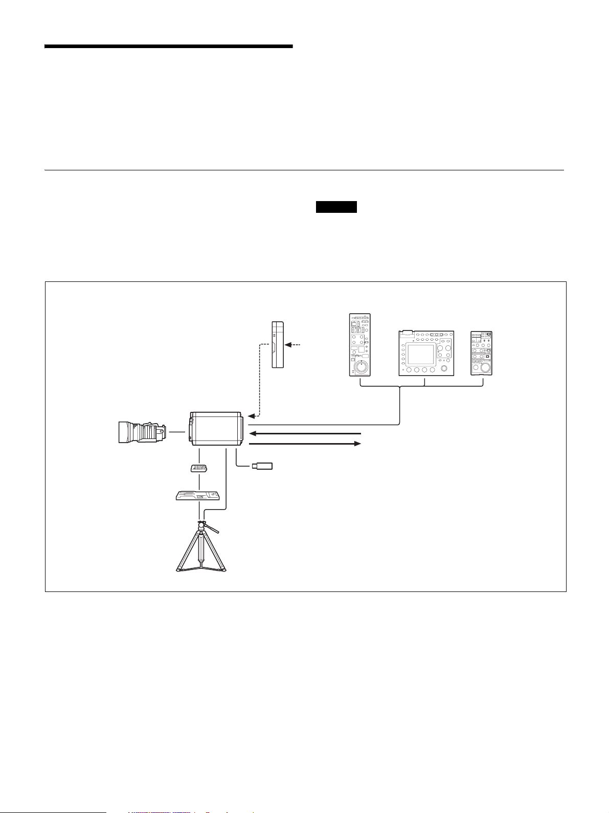
System Configuration
In addition to use as a standalone camera using the SDI output, you
can use this camera as a studio camera by directly connecting to the
Camera Control Unit (CCU) HXCU-FB70 using fiber cables.
This camera can be used for a wide range of applications such as
video production and security monitoring, as it is equipped with an
optical ND filter powered by a servo motor that can be operated from
a CCU, RCP, or RM, an electrical CC filter, a slow shutter capable
of storing up to 64 frames, a gain up to +48 dB, an x2 or x4 digital
extender (that enlarges the image by digital processing), and Total
Level Control System.
Peripherals and related devices for the camera are shown in figures.
Standalone operation example
AC Adapter
AC-DN10
Zoom Lens
(for ENG/EFP)
V shoe
Tripod adapter
VCT-14
Tripod for portable
camera
HXC-P70
CCA-5 cable/LAN cable
USB flash drive
Caution
Production of some of the peripherals and related devices shown in
the figures has been discontinued. For advice on choosing devices,
please contact your Sony dealer or a Sony sales representative.
Remote Control Panel
RCP-1000 Series
AC power
b)
Remote Control Unit
RM-B750/B170
Sync signal input
Video output (2-system)
HD-SDI/SD-SDI
a)
TEST
a)
(selectable)
a) No subcarrier phase-lock function with
respect to external reference is available
for the TEST signal output from the
camera.
b) A LAN cable can be used only to connect
the RCP-1500/1501. To connect it, power
needs to be supplied via a PoE hub or
power needs to be supplied to the EXT
DC IN connector of the RCP-1500/1501.
3
Page 4
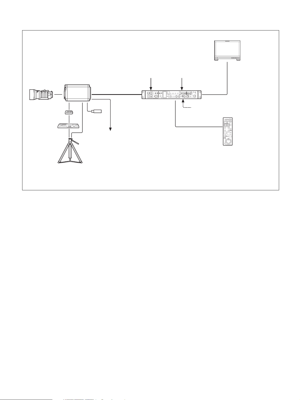
System operation example: When connected with an optoelectric composite cable
Picture monitor
Sync signal input Prompter video input
Zoom Lens (for
ENG/EFP)
Tripod adapter
VCT-14
Tripod for
portable camera
a) The maximum transmission distance is approximately 500 m when using Sony CCFN-25/50/100/150/200/250 Hybrid Fiber Cable (when camera head
+ portable lens).
b) A LAN cable can be used only to connect the RCP-1500/1501. To connect it, power needs to be supplied via a PoE hub or power needs to be supplied
to the EXT DC IN connector of the RCP-1500/1501.
V shoe
HXC-P70
Optoelectric composite
a)
cable
USB flash
drive
Prompter video output
Camera Control Unit
HXCU-FB70
HD-SDI/SD-SDI/VBS/HDMI video output
AC power
CCA-5 cable / LAN
b)
cable
Remote Control Panel
RCP-1000 Series
4
Page 5
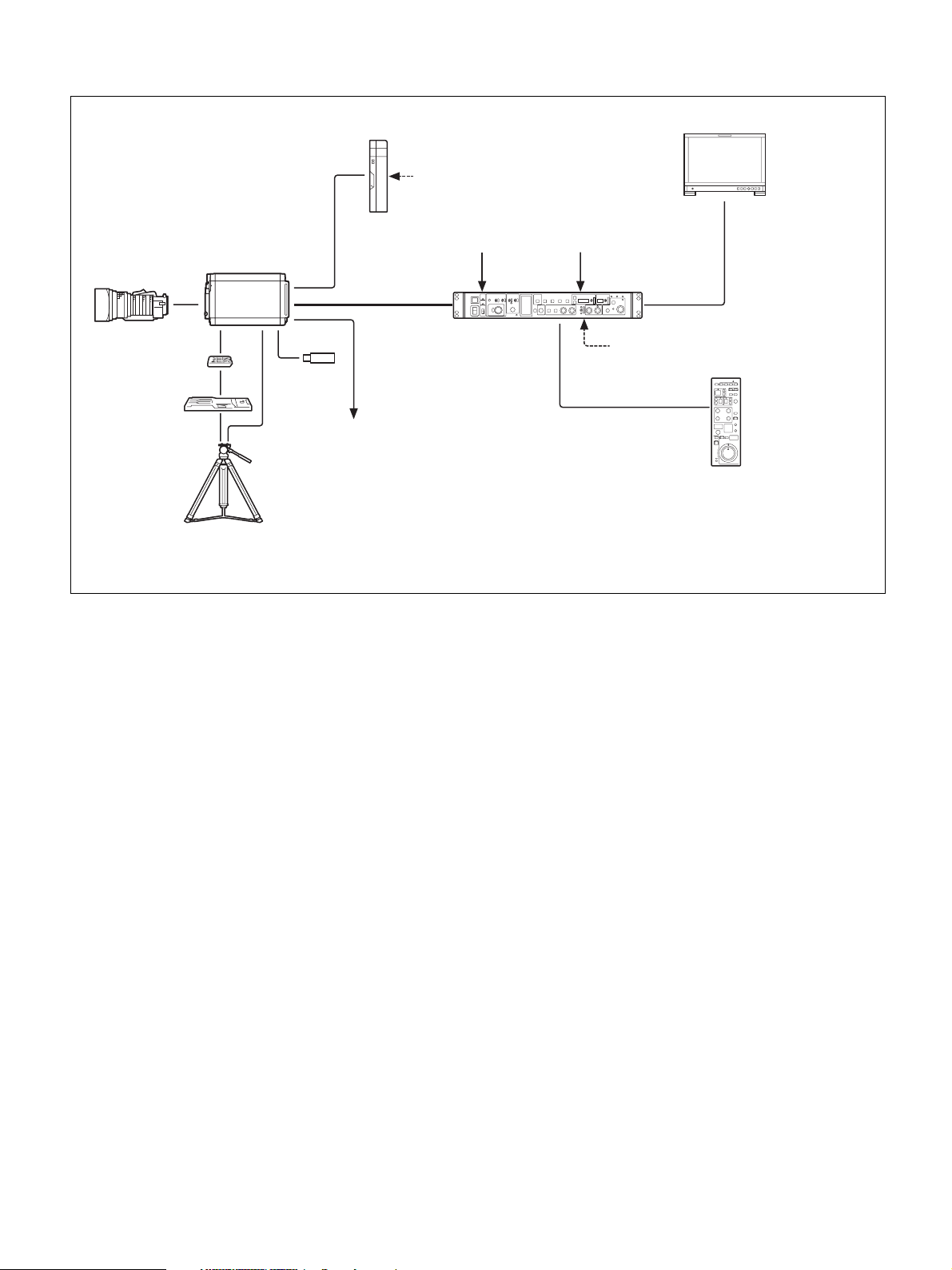
System operation example: When connected with single-mode optical fiber cables
Zoom Lens (for
ENG/EFP)
Tripod adapter
VCT-14
Tripod for
portable camera
V shoe
HXC-P70
AC Adapter
AC-DN10/DN2B
USB flash
drive
Prompter video output
AC power
Sync signal input Prompter video input
Single-mode
optical fiber cables
a)
(pair)
Camera Control Unit
HXCU-FB70
AC power
CCA-5 cable / LAN
b)
cable
Picture monitor
HD-SDI/SD-SDI/VBS/HDMI video output
Remote Control Panel
RCP-1000 Series
a) The maximum transmission distance is approximately 10 km when using general single-mode fiber cables with LC connectors.
b) A LAN cable can be used only to connect the RCP-1500/1501. To connect it, power needs to be supplied via a PoE hub or power needs to be supplied
to the EXT DC IN connector of the RCP-1500/1501.
5
Page 6
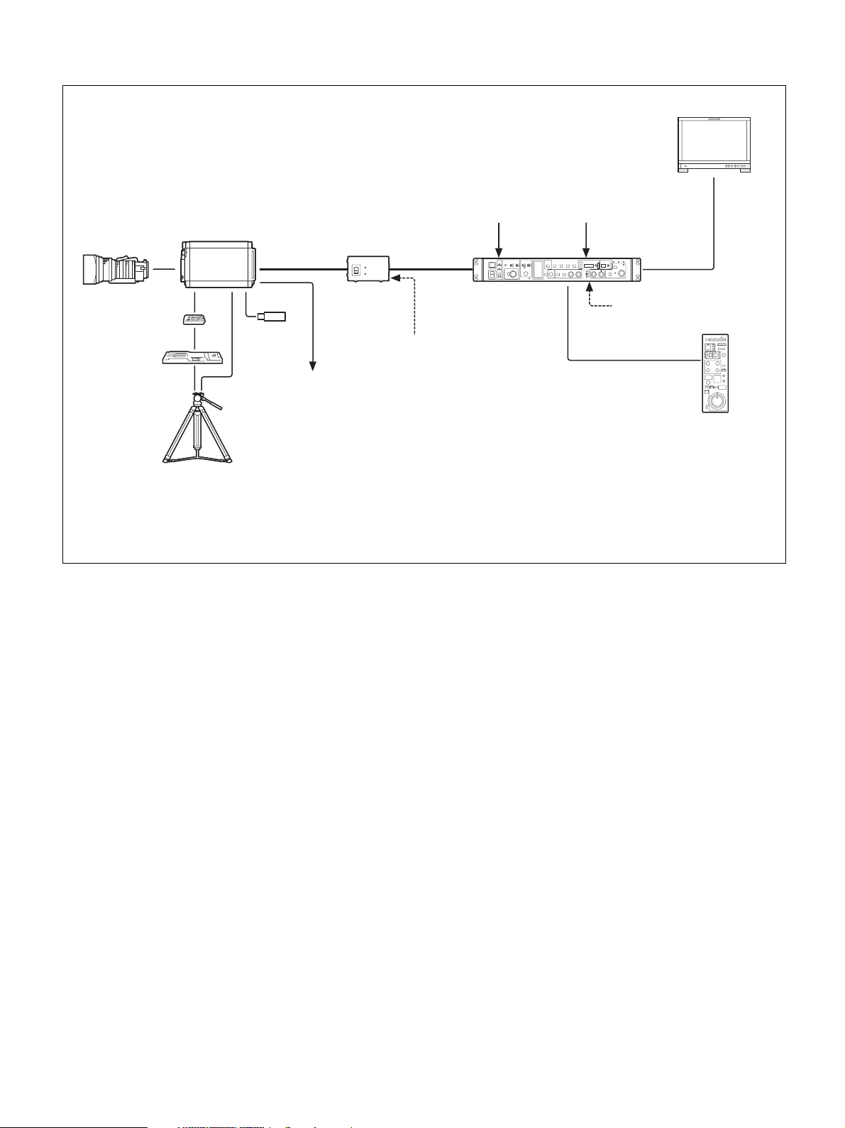
System operation example: When connected using Power Supply Unit HXCE-FB70
Sync signal input Prompter video input
Zoom Lens (for
ENG/EFP)
Tripod adapter
VCT-14
Tripod for
portable camera
HXC-P70
V shoe
Optoelectric
composite
a)
cable
USB flash
drive
Prompter video output
Power Supply
Unit
HXCE-FB70
AC power
Single-mode
optical fiber
b)
cables
Camera Control Unit
HXCU-FB70
HD-SDI/SD-SDI/VBS/
HDMI video output
AC power
CCA-5 cable / LAN
c)
cable
Remote Control Panel
RCP-1000 Series
Picture monitor
a) The maximum transmission distance is approximately 500 m when using Sony CCFN-25/50/100/150/200/250 Hybrid Fiber Cable (when camera head
+ portable lens).
b) The maximum transmission distance is approximately 10 km when using general single-mode fiber cables with LC connectors.
c) A LAN cable can be used only to connect the RCP-1500/1501. To connect it, power needs to be supplied via a PoE hub or power needs to be supplied
to the EXT DC IN connector of the RCP-1500/1501.
6
Page 7
Parts Identification
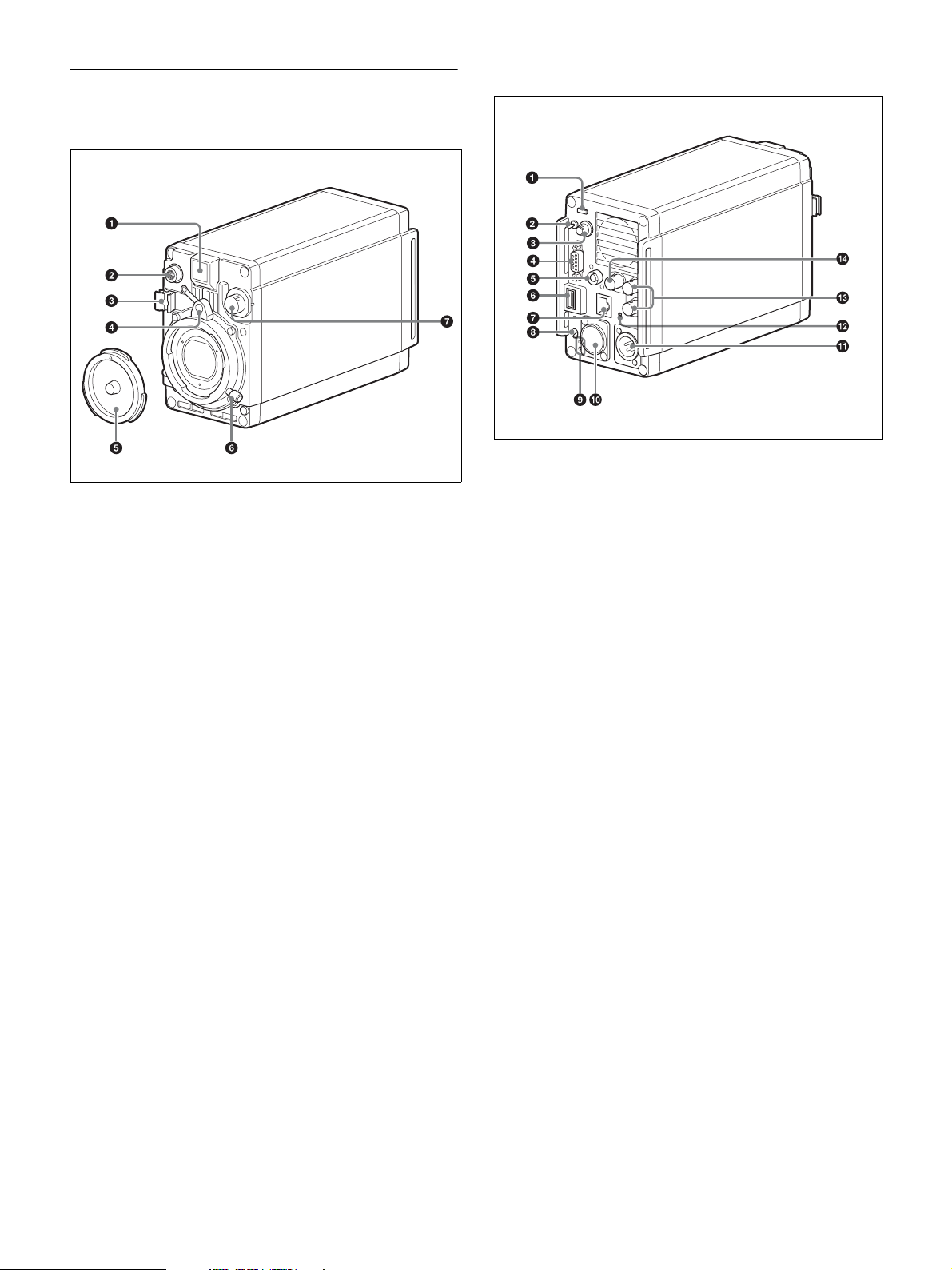
Front
a Front tally lamp
The tally lamp lights when a tally signal is input to the EXT I/O
connector of the HXCU-FB70 when the HXCU-FB70 is connected,
and when a tally signal is input to the EXT I/O connector of the
camera when it is used as a standalone camera.
The tally lamp does not light when a call signal is generated by
pressing the CALL button.
You can attach the supplied number plate to display the camera
number.
b LENS connector (12-pin)
Connect the cable of the lens (optional). The camera can control the
lens functions through this cable.
Connect the lens cable so that v is at the top.
c Lens cable clamp
d Lens mount safety rubber
e Lens mount cap
f Lens fixing lever
g ND filter select knob
To select the built-in ND filters (1: clear, 2: 1/4 ND, 3: 1/16 ND,
4: 1/64 ND).
Rear
a Rear tally lamp
The tally lamp lights when a tally signal is input and when a call
signal is generated, for example, by pressing the CALL button.
However, turning off the CALL setting on the M06 <TALLY> page
disables the tally lamp when a call signal is generated by pressing
the CALL button.
The rear tally lamp also serves as a battery alarm function.
If the voltage of the XLR input connected to the camera decreases,
the rear tally lamp flashes, and if the limit becomes close to being
reached, the rear tally lamp switches to high-speed flashing.
The alarm voltage for starting flashing can be set in the BEFORE
END item of the <BATTERY ALARM> page on the
MAINTENANCE menu, and the alarm voltage for switching to
high-speed flashing can be set in the END item.
If a call signal is generated while the battery alarm function is
operating, the rear tally lamp goes out.
If you want to operate the tally function and call function, set the
BATTERY ALARM item of the <BATTERY ALARM> page on the
MAINTENANCE menu to OFF.
For details, see “MAINTENANCE Menu” (page 25).
b DISPLAY/MENU switch
Select the display on the screen connected to the SDI connector (VF
Setting) or GL/TEST connector.
D IS PL AY: To display various textual information, such as
messages showing the camera settings and operating status, in
addition to camera images.
z (OFF): To not display textual information and markers.
MENU: To display menus for camera settings, in addition to camera
images.
c Menu control knob (rotary encoder)
Used to select settings from menus (by rotating it) and to confirm
settings (by pushing it).
d EXT I/O (external input/output) connector (D-sub, 9-pin)
Connect an external device.
7
Page 8
e REMOTE connector (8-pin)
For connection to an RM-B170/B750 Remote Control Unit,
RCP-1000 Series Remote Control Panel, or another external control
device.
Note
When using the camera by connecting to a camera control unit, do
not connect, for example, a remote control panel to this connector.
f (USB) connector
Connect a USB flash drive to save or load a configuration data file.
g (LAN) connector (RJ-45 type, 8-pin)
To connect to a LAN. Use a LAN cable (shielded, category 5 or
above) to connect to the hub of the LAN (10BASE-T/100BASETX).
h CAMERA POWER switch and indicator
To turn the power ON/OFF.
ON: Set the switch to the ? side. The indicator lights green.
OFF: Set the switch to the 1 side.
i CONDITION indicators
To indicate the communication status and power status of the camera
and CCU based on the light reception level and the voltage reaching
the camera.
HD-SDI signal and SD-SDI signal output can be selected on the
menu.
Note
The functions that can be displayed differ depending on the output
settings.
For details on the adjustment, see “Connector Output Settings and
Display Functions” (page 8).
n GL/TEST (external sync signal input/TEST signal output)
connector
Select external sync signal (BB or tri-level) input to sync the camera
or TEST signal output.
Note
Even when a BB signal is used for the external sync signal, no
subcarrier phase-lock function is available for the TEST output
signal.
Connector Output Settings and Display
Functions
The functions that can be displayed differ depending on the
connector output settings.
Indication Meaning
Both top and bottom lit green State is excellent.
Only bottom lit green State is fairly good.
Only top lit yellow State has deteriorated.
Only bottom lit red State has become extremely poor (the
connection between the camera and CCU
needs to be checked).
j CCU (Camera Control Unit) connector (optoelectric
composite connector)
To connect to the HD Camera Control Unit HXCU-FB70.
When connected with an optoelectric composite cable, all the
signals of the camera including the power supply, control signals,
video signals, and audio signals can be transmitted/received with the
one optoelectric composite cable.
When connected with a pair of single-mode fiber cables, all the
signals except the power supply can be transmitted/received with the
pair of single-mode fiber cables.
k DC IN (DC power supply input) connector (XLR 4-pin)
For connection to an AC-DN10 AC adapter, etc. to supply power to
the camera.
l NETWORK indicator
To indicate the state when connected to a network system.
Lit: Successfully connected to an external control device
(RCP-1000 Series remote control panel, etc.).
Flashing: Unable to connect to an external control device
(RCP-1000 Series remote control panel, etc.) properly.
Off: A LAN cable is not connected or the connection settings of the
network system are not configured.
For details on the adjustment, see “Configuring Control System
Connection Settings” (page 12), “MAINTENANCE Menu”
(page 25), “DIAGNOSIS Menu” (page 30).
Connector
name
SDI 1 MAIN/
SDI 2MAINHDYesYes NoNoNo
GL/
TEST
a) The focus assist functions include the VF DETAIL function
b) When the GL/TEST connector is set to TEST output (VBS) to output a
c) Linked to the DISPLAY/MENU switch setting.
d) A function can be set to ON/OFF on the OPERATION menus 02 and 05.
Output
setting
SD-SDI
VF HD Yes Yes Yes Yes Yes
RETHDYesYes NoNoNo
SD-SDI SD Yes Yes No No No
VBS
b)
OUT
(OPERATION menu 03) and FOCUS ASSIST INDICATOR function
(OPERATION menu 04).
TEST signal.
Format
Setting
menus
HD/SDNo No No No No
SD Yes Yes No No No
Display functions
Operation
c)
c)
status
Markerd)Zebrad)Focus
assist
a)
m SDI 1 (serial digital interface) connector and SDI 2
connector (BNC type)
For HD-SDI or SD-SDI signal output.
8
Page 9
Installation
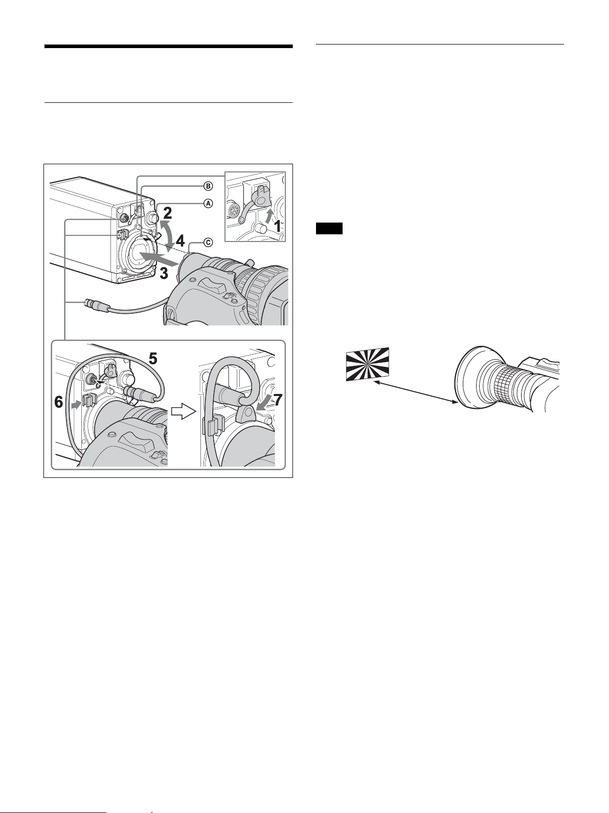
Attaching a Lens
For information on handling lenses, refer to the operation manual
for the particular lens
B
A
C
Adjusting the Flange Focal Length
Adjustment of the flange focal length (the distance between the lens
mount attachment plane and the imaging plane) is necessary in the
following situations:
• The first time a lens is attached
• When changing lenses
• If the focus is not sharp at both telephoto and wide angle when
zooming
The flange focal length can be more precisely adjusted by using the
focus assist indicators.
See “Displaying the focus assist indicators” (page 14) for the focus
assist indicators.
Note
The various parts of the lens used in adjusting the flange focal length
are in different positions on different lenses. Refer to the operation
manual for the lens.
1 Set the iris control to manual and open the iris fully.
2 Place a flange focal length adjustment chart approximately
3 meters from the camera and adjust the lighting to get an
appropriate video output level.
1 Remove the lens mount safety rubber.
2 Push the lens fixing lever A upward and remove the lens
mount cap from the lens mount.
3 Align the lens’ alignment pin C with the notch B in the
upper part of the lens mount and insert the lens into the
mount.
4 While supporting the lens, push the lens fixing lever A
downward to secure the lens.
5 Connect the lens cable to the LENS connector.
6 Secure the lens cable with the cable clamp.
About 3 meters
(10 ft)
3 Loosen the Ff (flange focal length) ring lock screw.
4 With either manual or power zoom, set the zoom ring to
telephoto.
5 Aim at the flange focal length adjustment chart and turn
the focus ring to focus the image.
6 Set the zoom ring to wide angle.
7 Turn the Ff ring to bring the chart into focus.
Take care not to move the distance ring.
8 Repeat steps 4 through 7 until the image is in focus at both
telephoto and wide angle.
9 Tighten the Ff
ring lock screw.
7 Reattach the lens mount safety rubber.
9
Page 10
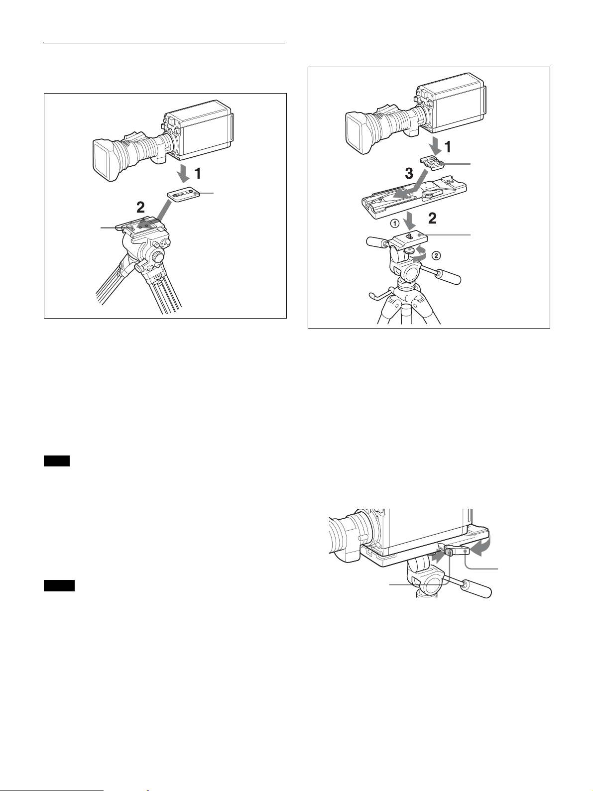
Mounting the Camera to a Tripod
When using tripod attachment adapter
details on purchasing parts, contact a Sony service representative
or Sony sales representative.
V shoe
Tripod attachment
adapter
Platform
1 Attach the tripod attachment adapter directly to the
camera.
(Two 3/8-inch tripod screws: screw depth of 10 mm (13/
32 inches) or less)
2 Place the camera on the tripod and mount the camera by
sliding it forward along the groove of the platform until it
clicks into place.
3 Move the camera back and forth, and check that it is
securely fixed.
Note
If the screws of the tripod attachment adapter are 1/4-inch tripod
screws, use inch conversion screws (Sony Part No.: 4-170-419-02)
to attach the adapter. For details on purchasing inch conversion
screws, and other information, contact a Sony service representative
or Sony sales representative.
Tripod adapter
Platform
1 Attach the V shoe to the camera with the attachment
screws.
2 1Attach the tripod adapter to the tripod and 2 secure it
with the screw.
3 Place the camera on the tripod adapter and slide forward it
along the groove of the tripod adapter until it clicks.
4 Move the camera back and forth, and check that it is
securely fixed.
To remove the camera from the tripod adapter
Hold down the red button and pull the lever in the direction of the
arrow.
When using V shoe and tripod adapter VCT-14
Use a separately sold V shoe (Sony Part No.: A-8279-993-D) and
tripod adapter VCT-14 to mount the camera to the tripod.
Notes
• Select an appropriate hole from among those at the bottom of the
tripod adapter considering the balance of the weight of the camera
and the tripod adapter. If an inappropriate hole is selected, the
camera may fall over.
• Check that the size of the selected hole matches that of the screw
of the tripod. If they do not match, the tripod adapter cannot be
attached to the tripod securely.
• Use the following screws when attaching a separately sold V shoe.
Attachment screws: Four Alok + K4 × 8 screws
(Sony Part No.: 3-729-072-02)
Do not use screws that are 5 mm or longer for the camera. For
Lever
Red button
If the pin of the tripod adapter does not return to its
original position
After removing the camera, if the pin of the tripod adapter does not
return to its original position, hold down the red button and move the
lever in the direction of the arrow to return the pin to its original
position. It is not possible to mount a camera with the pin not seated.
10
Page 11
Original position
Pin
4 Change the SYSTEM LINE (video resolution) and
SYSTEM SCAN (video scanning mode) settings according
to the video format you are using.
SYSTEM LINE
Setting value Resolution (horizontal x vertical)
1080 1080 line (1920 x 1080)
720 720 line (1280 x 720)
SYSTEM SCAN
Setting the Area of Use
When using the camera for the first time
The camera is shipped with the area of use setting in an unset state.
To use the camera, you need to first set the area of use.
Once the area setting is complete, set the current date and time.
For details on setting the date and time, see “Setting the Local
Time” (page 11).
Note
The camera cannot be used if the area of use is not set.
Setting the area of use
1 Turn on the camera.
The area of use setting screen appears on the monitor connected
to the GL/TEST connector output or SDI 2 connector.
FO MAT SET T I NG
C O U N T RRY: NOT SELECT
SYSTEM L I NAE:108
SYSTEM SC N: Inter lace
SET FORMAT
AND TURN OF F ONCE .
ED
0
2 Push on the menu control knob.
The area of use becomes selectable.
FO MAT S ET T I NG
C O U N T RRY: NOT SELECT
SYSTEM L I NAE:108
SYSTEM SC N : I n t e r l a c e
SET FORMAT
AND TURN OF F ONCE .
?
ED
0
Setting value Video scanning mode
Interlace Interlace
Progressive Progressive
PsF PsF
Supported formats: 1080/59.94i, 1080/50i, 1080/29.97PsF,
1080/25PsF, 720/59.94P, 720/50P
5 Turn the camera off and then back on.
The camera becomes able to be used.
Changing the area of use
Change the setting in the COUNTRY item on the <OUTPUT
FORMAT> page of the MAINTENANCE menu.
Note
The setting is switched to the CCU setting when a CCU is
connected.
Setting the Local Time
Set the built-in clock to the current local time on the <DATE> page
of the MAINTENANCE menu.
For details on menu operations, see “Menus” (page 16).
1 Turn on the camera.
2 While holding the menu control knob pressed, set the
DISPLAY/MENU switch to MENU.
The camera enters Menu mode, and “TOP” is displayed at the
upper-right corner of the screen.
3 Rotate the menu control knob to select the area of use.
Setting
value
NTSC(J)
AREA
NTSC
AREA
PA L
AREA
Area of use Output
composite
signal
NTSC area
(for within Japan)
NTSC area
(for areas other
than Japan)
PAL area PAL signal 50i
NTSC signal
without setup
NTSC signal
with setup
(7.5IRE)
Systemfrequency
59.94i
59.94i
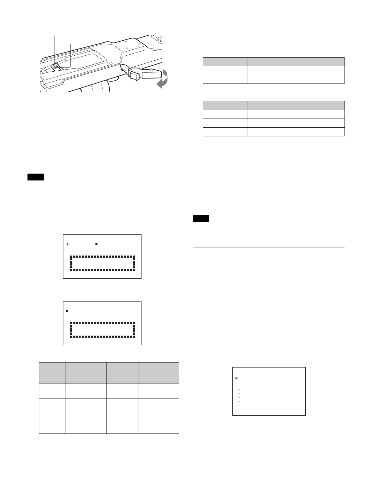
3 Rotate the menu control knob to set the cursor to “TOP”
and push on the menu control knob.
The TOP MENU screen is displayed.
<TOP MENU>
USER
USER MENU CUSTOMIZE
ALL
OPERATION
PAINT
MAINTENANCE
FILE
DIAGNOSIS
11
Page 12
4 Rotate the menu control knob to position the cursor to
MAINTENANCE and push on the menu control knob.
The CONTENTS page of the MAINTENANCE menu is
displayed.
CONTENTS M00 TOP
01.<AUTO SETUP>
02.<WHITE SHADING>
03.<BLACK SHADING>
04.<AUTO IRIS>
05.<LENS>
06.<CIS COMP>
07.<TALLY>
08.<OUTPUT FORMAT>
09.<GL/TEST OUT>
10.<SDI OUT>
5 Turn the menu control knob to scroll the page and position
the pointer to <DATE> then push on the menu control
knob.
The <DATE> page is displayed.
<DATE> M13 TOP
DATE/TIME
2015/12/23 08:32
6 Turn the menu control knob and set the date and time.
Push on the menu control knob to shift to the next digit.
Preparatory Settings
Configuring Control System
Connection Settings
There are the following three modes for the control system of the
camera.
• LEGACY mode: This setting mode is for when controlling the
camera from an external control device via the REMOTE
connector of the camera.
• BRIDGE mode: This setting mode is for when controlling the
camera from an external control device via the LAN connector of
the camera on a one-to-one basis.
• PC CONTROL mode: This mode is for when controlling the
camera from a HZC-RCP5 via a LAN cable.
Use the MAINTENANCE menu to set the mode.
For details on menu operations, see “Menus” (page 16).
Note
When the control system connection mode is changed, turn the
power of all devices in the system off and then back on.
7 When the date/time setting is completed, set the DISPLAY/
MENU switch to OFF to exit Menu mode.
To connect in LEGACY mode
Set CNS MODE to LEGACY.
For details, see “CNS SETTINGS (MAINTENANCE menu)”
(page 13).
Note
When a LAN cable will not be connected directly to the camera even
when building a camera network system using a LAN, set CNS
MODE to the LEGACY mode.
To connect in BRIDGE mode
1 Set CNS MODE to BRIDGE.
For details, see “CNS SETTINGS (MAINTENANCE menu)”
(page 13).
2 Configure settings related to TCP/IP.
For details, see “TCP/IP SETTING (MAINTENANCE menu)”
(page 13).
3 Set the LAN connection.
For details, see “LAN SETTINGS (MAINTENANCE menu)”
(page 13).
4 Set the IP address of the camera for “target IP address” of
the RCP to be connected to the LAN.
For details, see the operation manual of the RCP.
To connect in PC CONTROL mode
To use the camera in PC CONTROL mode, you need one PC with
HZC-RCP5 (option) installed.
12
Page 13

1 Set CNS MODE to PC CONTROL.
For details, see “CNS SETTINGS (MAINTENANCE menu)”
(page 13).
2 Set CCU NO.
For details, see “CNS SETTINGS (MAINTENANCE menu)”
(page 13).
3 Set TARGET IP ADDRESS.
For details, see “CNS SETTINGS (MAINTENANCE menu)”
(page 13).
DUPLEX MODE: Display the communication system of the LAN
line.
CNS SETTINGS (MAINTENANCE menu)
<CNS SETTINGS> M18 TOP
CNS MODE : LEGACY
CCU NO : 0
TARGET IP ADDRESS:
0. 0. 0. 0
SET
4 Configure settings related to TCP/IP.
For details, see “TCP/IP SETTING (MAINTENANCE menu)”
(page 13).
5 Set the LAN connection.
For details, see “LAN SETTINGS (MAINTENANCE menu)”
(page 13).
6 Configure the settings of the PC to be connected by LAN.
For details, see the manuals for the PC and HZC-RCP5.
Note
Set CCU NO to a number that is not a duplicate of any of the CCU
device numbers in the system.
About the menu to configure the control
system connection settings
TCP/IP SETTING (MAINTENANCE menu)
<TCP/IP SETTING> M16 TOP
IP ADDRESS:
0. 0. 0. 0
SUBNET MASK:
0. 0. 0. 0
DEFAULT GATEWAY:
0. 0. 0. 0
SET
IP ADDRESS: Set the IP address to assign to the camera.
SUBNET MASK: Set the subnet mask of the network environment.
DEFAULT GATEWAY: Set the default gateway of the network
environment if necessary.
LAN SETTINGS (MAINTENANCE menu)
CNS MODE: Set the control system connection mode.
LEGACY: Set the mode to the LEGACY mode.
BRIDGE: Set the mode to the BRIDGE mode.
PC CONTROL: Set the mode to the PC CONTROL mode.
CCU NO: Set the device number (camera number) of the camera
when using the PC CONTROL mode. Set a number that is not a
duplicate of any of the CCU device numbers in the system.
TARGET IP ADDRESS: Set the IP address of the PC with HZC-
RCP5 in PC CONTROL mode.
Resetting the network configuration
information
<NETWORK RESET> M19 TOP
NETWORK ALL RESET
NETWORK ALL RESET: Restore the network related
information to the default state.
Setting the TLCS Function
You can maintain the proper exposure by using the TLCS (Total
Level Control System) function. This function controls not only the
iris, but also the shutter (AUTO SHUTTER) and gain (AGC: Auto
Gain Control) automatically.
The TLCS function can be assigned to one of the ASSIGN 1/2/3
buttons, and turned on/off by pressing the button.
The effective auto control range is set as shown in the following
diagram on the <TLCS> in the OPERATION menu.
<LAN SETTINGS> M17 TOP
CONNECTION SPEED : 100M
DUPLEX MODE : FULL
The LAN interface of the camera supports Auto Negotiation. The
connection speed (SPEED) and communication system (DUPLEX)
are automatically set depending on the connected device.
CONNECTION SPEED: Display the connection speed of the
LAN line.
Bright Subject Dark
Iris closed Iris openAuto iris
Restores auto iris control if
the LIMIT value is exceeded.
13
Restores auto iris control if
the LIMIT value is exceeded.
Page 14

Notes
• Both AUTO SHUTTER and AGC switch on/off in response to the
button assigned with the TLCS function. You can turn them on/off
individually on the <TLCS> page in the OPERATION menu.
• SLS mode and AUTO SHUTTER cannot be used at the same
time. The last enabled function takes precedence.
Setting the Focus Assist Function
Using the OPERATION menu, you can display the assist functions
for easier focusing on the monitor screen connected to the SDI2
connector (VF Setting).
Adding a VF detail signal
Adding a VF detail signal to sharp edges in the image on the monitor
screen makes it easier to check the focusing condition by observing
changes in the detail signal or in the color converted from the detail
signal (color detail).
The focus setting where the detail signal becomes strongest is the
best focus setting.
1 Turn on the camera.
2 Set the DISPLAY/MENU switch to MENU while holding
the menu control knob pressed.
The camera enters Menu mode, and “TOP” is displayed at the
upper right corner of the screen.
3 Rotate the menu control knob to align the pointer (,) to
“TOP” and push on the knob.
The TOP MENU screen is displayed.
<TOP MENU>
USER
USER MENU CUSTOMIZE
ALL
OPERATION
PAINT
MAINTENANCE
FILE
DIAGNOSIS
4 Rotate the menu control knob to align the pointer (,) to
OPERATION and push on the knob.
The CONTENTS page of the OPERATION menu is displayed.
CONTENTS 00 TOP
01.<VF DISPLAY>
02.<VF MARKER>
03.<VF DETAIL>
04.<FOCUS ASSIST>
05.<ZEBRA>
06.<CURSOR>
07.<VF OUT>
08.<TLCS>
09.<OPERATOR FILE>
5 Rotate the menu control knob to align the pointer (,) to
<VF DETAIL> and push on the knob
The <VF DETAIL> page is displayed.
<VF DETAIL> 03 TOP
VF DETAIL : ON 8%
CRISP : 0
FREQUENCY: 9M
FLICKER : OFF
AREA : 70%
ZOOM LINK: 100%
COLOR DETAIL : ON BLUE
PEAK COLOR : ON
CHROMA LEVEL: 100%
6 Rotate the menu control knob to align the pointer (,) to
the item to be set and push on the knob.
To use the VF detail signal
Set VF DETAIL to ON to activate the VF detail function to add
the detail signal to sharp edges in the image. You can adjust the
signal level (strength) in the range of 0 to 100% (default: 8%).
You can adjust the characteristics of the detail signal with the
menu items below:
CRISP: Adjust to eliminate fine portions of the detail signal.
FREQUENCY: Change the detection band of sharp edges.
FLICKER: Set the function for flickering the detail signal to
ON/OFF. (Setting the function to ON makes it easier to
check the detail signal on a CRT screen.)
AREA: To limit the area where to display the detail signal.
ZOOM LINK: Set the VF detail level at the full WIDE
position. (The VF detail level changes according to the
zoom position. The default setting is 100% with no change
at the full WIDE position. It becomes half at 50%.)
To use the color detail
Set COLOR DETAIL to ON to convert the VF detail signal to
a specified color. The display color can be selected in the
column on the right of ON.
You can adjust the coloring with the menu items below:
PEAK COLOR: Turn the function ON/OFF to change the
color where the detail signal is strongest.
CHROMA LEVEL: To reduce the chroma components of the
video signal.
7 Rotate the menu control knob to display the desired setting
and push on the knob.
8 To finish the adjustments, set the DISPLAY/MENU switch
to OFF to exit Menu mode.
Displaying the focus assist indicators
The focus assist indicator function extracts the irregularities of a
subject, converts the integrated values to a level indicator, and shows
it on the monitor screen connected to the SDI2 connector (VF
Setting).
14
Page 15

Level indicator (Its position and operations can be adjusted.)
Area marker to display the detection area of the
focus (Its size and position can be adjusted.)
The focus setting where the indicator shows the maximum level is
the best focus setting. (The range of the indicator substantially
changes depending on the picture elements or shooting
environment. Adjust it with GAIN and OFFSET as necessary.)
1 Display the CONTENTS page of the OPERATION menu
(referring to step 1 to 4 in “Adding a VF detail signal”).
2 Rotate the menu control knob to align the pointer (,) to
<FOCUS ASSIST> and push on the menu control knob.
The <FOCUS ASSIST> page is displayed.
<FOCUS ASSIST> 04 TOP
INDICATOR : OFF
MODE : BOX BOTTOM
LEVEL : 3 QUICK
GAIN : 50
OFFSET : 50
AREA MARKER: ON
SIZE : MIDDLE
POSITION : CENTER
POSITION H: 50
POSITION V: Finely adjust the position of the detection area
in the vertical directions.
4 Rotate the menu control knob to display the desired setting
and push on the knob.
5 To finish the adjustments, set the DISPLAY/MENU switch
to OFF to exit Menu mode.
Notes
• The INDICATOR and effect area marker cannot be displayed at
the same time. The one that was set to ON last takes priority.
• The AREA MARKER and aspect safety marker cannot be
displayed at the same time. The one that was set to ON last takes
priority.
• When displaying the focus assist indicators, check that the flange
focal length has been precisely adjusted.
See “Adjusting the Flange Focal Length” (page 9) for the flange
focal length.
3 Rotate the menu control knob to align the pointer (,) to
the item to be set and push on the knob.
To use the level indicator
Setting INDICATOR to ON displays the level indicator on the
monitor. You can set the display format with the menu items
below.
MODE: Set the type and position of the indicator.
LEVEL: Set the density and the response speed of the
indicator.
GAIN: Set the sensitivity of the indicator.
OFFSET: Set the offset of the focus detection value.
1) Normally, the sensitivity of the indicator is automatically set to the
optimum value in conjunction with the AREA MARKER SIZE set
value. Use this setting when an optimum sensitivity value cannot be
obtained, depending on the shooting environment.
2) Normally, the optimum offset is automatically set in conjunction
with the AREA MARKER SIZE and MASTER GAIN set values.
Use this setting when the optimum offset cannot be obtained,
depending on the shooting environment.
To use the area marker
Setting AREA MARKER to ON displays the detection area of
the focus as a marker on the monitor.
You can set the size and position of the detection area with the
menu items below.
SIZE: The size of the detection area can be changed. (If the
area size is too large, both the subject and the background
are included in the area, making the indicator display easily
deviate from the subject.)
POSITION: Roughly set the position of the detection area.
POSITION H: Finely adjust the position of the detection area
in the horizontal directions.
1)
2)
15
Page 16

Menus
The menus displayed on the monitor connected to the TEST signal
output or SDI 2 connector enable various settings of the camera to
be configured.
The following controls are used to operate the menus.
Turn the menu control knob on the rear panel to select menu items
or values, and push on it to register (enter) the selection.
Rear
Menu control knob
Push onRotate
DISPLAY/MENU switch
Operating the Menu
Menu Purpose
USER This menu can include menu pages selected from
USER MENU
CUSTOMIZE
ALL This menu permits you to control all items of the
OPERATION
(page 20)
PA IN T (page 22) This menu contains items for making detailed image
MAINTENANCE
(page 25)
FILE (page 28) This menu is for performing file operations, such as
DIAGNOSIS
(page 30)
among the OPERATION, PAINT, MAINTENANCE,
FILE, and DIAGNOSIS menus, for convenience (see
the table on page 18 for the default configuration).
Changing, adding, and deleting pages can be
performed with the USER MENU CUSTOMIZE
menu.
This menu allows you to edit the USER menu.
For details, see “Editing the USER Menu” (page 17).
OPERATION menu, PAINT menu, MAINTENANCE
menu, FILE menu, and DIAGNOSIS menu as a single
menu.
This menu contains items for camera operators to
operate the camera. It mainly permits switch settings.
adjustments while using a waveform monitor to
monitor the waveforms output from the camera.
Support of a video engineer is usually required to use
this menu.
Although you can also use an external control device
to set the items on this menu, the menu is effective
when using the camera by itself outdoors.
This menu contains items for performing camera
maintenance operations, such as changing the system
or setting infrequently used “paint” items.
writing or clearing the reference file.
This menu enables you to confirm the self-diagnostic
information.
To display a menu page
Set the DISPLAY/MENU switch to MENU.
The menu page last accessed will be displayed. If it is the first time,
the CONTENTS page of the USER menu will be displayed.
To display the TOP MENU screen
If you set the DISPLAY/MENU switch to MENU while holding the
menu control knob pressed, “TOP” is displayed at the upper right
corner of the screen.
Turn the menu control knob to move the pointer (,) on the display
to “TOP” and push on the knob. The TOP MENU screen is
displayed, listing the available menus.
<TOP MENU>
USER
USER MENU CUSTOMIZE
ALL
OPERATION
PAINT
MAINTENANCE
FILE
DIAGNOSIS
To select a menu on the TOP MENU screen
Rotate the menu control knob to align the pointer (,) with the
desired menu indication then push on the knob.
The CONTENTS page (page No. 00) or the last accessed page of the
selected menu is displayed.
Selecting the Page
To select a page from a CONTENTS page
Rotate the menu control knob to align the pointer (,) with the
desired page indication then push on the menu control knob.
If the screen can be scrolled, arrows will indicate
the direction for scrolling.
CONTENTS P00 TOP
01.<SW STATUS>
02.<VIDEO LEVEL>
Pointer (,)
03.<COLOR TEMP>
04.<GAMMA>
05.<BLACK GAMMA>
06.<SATURATION>
07.<KNEE>
08.<WHITE CLIP>
09.<DETAIL 1>
10.<DETAIL 2>
16
Page 17

The selected page is displayed.
<GAMMA> P04 TOP
[R] [G] [B] [M]
LEVEL : 0 0 0 0
COARSE : 0.45
Page number
To specify a character string
When you press the menu control knob with the pointer (,)
pointing to an item for which a character string, such as a file ID, is
to be specified, a cursor and the list of selectable characters are
displayed.
The displayed cursor can be moved by rotating the menu control
knob.
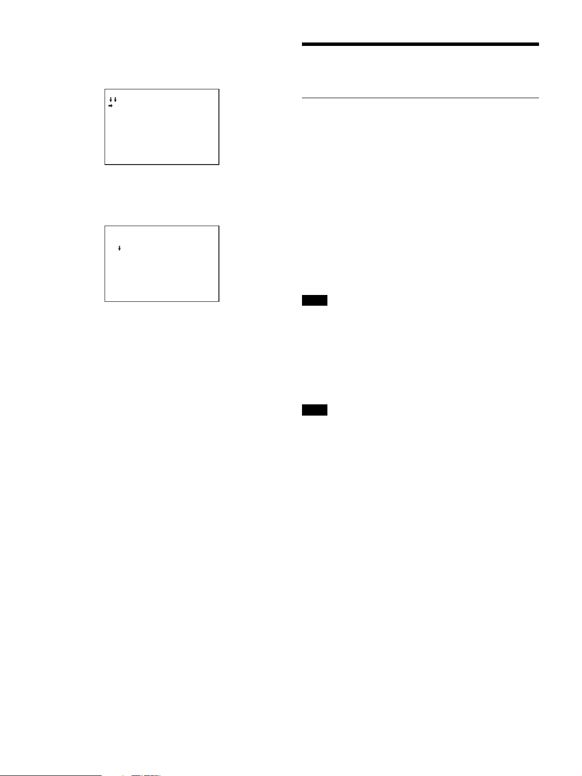
To change the displayed page
1 Check that the pointer (,) is located at the left of the page
number then push on the menu control knob.
The pointer (,) changes to a flashing question mark.
flash
<GAMMA> ? P04 TOP
[R] [G] [B] [M]
LEVEL : 0 0 0 0
COARSE : 0.45
2 Rotate the menu control knob to flip through the pages, and
push on the knob when the desired page is displayed.
The question mark will change back to the pointer (,), and
operations with the displayed page are enabled.
To return to the TOP MENU screen
Align the pointer (,) with “TOP” at the top right of the menu
page then push on the menu control knob.
<GAMMA> P04 TOP
[R] [G] [B] [M]
LEVEL : 0 0 0 0
:
.
Setting the Menu Items
If a question mark is flashing at the left of the page number, push on
the menu control knob to change it to the pointer (,). Operation on
the displayed page is enabled.
1 Align the pointer (,) with the desired item, then push on
the menu control knob.
The pointer (,) changes to a flashing question mark.
2 Rotate the menu control knob to change the setting value.
When the knob is rotated quickly, the values will change
quickly; when rotated slowly, the values will change slowly.
To interrupt settings
Set the DISPLAY/MENU switch to OFF to turn off the menu
screen display.
The setting operation can be restarted by setting the DISPLAY/
MENU switch back to MENU.
1 Set the cursor to the position where you wish enter a
character, then push on the menu control knob.
Another cursor appears on the character list.
2 Set the cursor to the character to be entered and push on the
menu control knob.
Repeat steps 1 and 2.
• By selecting INS on the line below the character list, you can
enter a space at the cursor position.
• Selecting DEL deletes the character at the cursor position.
• You can return to step 1 without changing the character by
selecting RET.
• If you enter the permitted maximum number of characters
(up to the stop mark at the right end of the line), the cursor
moves to ESC on the line below the character list.
3 Select END and push on the menu control knob.
The new string you have set is registered.
To reset a changed value
Select ESC and push on the menu control knob.
Restoring a setting to the default setting
When an item is selected and , is displayed, pressing and holding
the menu control knob for 3 seconds restores the setting value to the
state in the reference file. If 10 SEC CLEAR of the FILE CLEAR
page on the FILE menu is set to ON, pressing the control knob for
another 10 seconds restores the reference file value of the selected
item to the default state.
To end menu operations
Set the DISPLAY/MENU switch to OFF.
Editing the USER Menu
You can select desired pages and items from the OPERATION,
PAINT, MAINTENANCE, FILE, and DIAGNOSIS menus and
register them to the USER menu.
If you specify pages or items frequently used for the USER menu,
you can easily call and use them.
The following pages are included on the factory-set USER menu:
3 Push on the menu control knob.
The question mark will change back to the pointer (,), and the
new setting will be registered.
4 To change other setting items on the same menu page,
repeat steps 1 through 3.
17
Page 18

Menu page title USER
menu No.
<VF OUT> U01 OPERATION 07
<VF DETAIL> U02 OPERATION 03
<FOCUS ASSIST> U03 OPERATION 04
<VF DISPLAY> U04 OPERATION 01
<VF MARKER> U05 OPERATION 02
<CURSOR> U06 OPERATION 06
<ZEBRA> U07 OPERATION 05
<OUTPUT FORMAT> U08 MAINTENANCE M08
<SDI OUT> U09 MAINTENANCE M10
<TRUNK> U10 MAINTENANCE M11
<ROM VERSION> U11 DIAGNOSIS D03
Source menu/
page No.
For the items on each page, see “OPERATION Menu” (page 20),
“MAINTENANCE Menu” (page 25), or “DIAGNOSIS Menu”
(page 30).
The USER MENU CUSTOMIZE menu allows you to configure the
USER menu as follows:
• Creating a new menu page and selecting and adding (registering)
items that you use very frequently from multiple menu pages.
• Deleting (unregistering) added items.
• Changing the order of added items.
• Adding (registering) a menu page (new page you create or
existing menu page) to the USER menu.
• Deleting (unregistering) a page from the USER menu.
• Changing the order of pages of the USER menu.
Editing at the item level
The USER MENU CUSTOMIZE menu allows you to create a new
page for the USER menu and add any item.
Initially, the EDIT page of the USER MENU CUSTOMIZE already
contains items but the USER 1 EDIT to USER 19 EDIT pages are
blank. Up to 10 items can be selected and registered to these pages
from different menu pages.
To add items to a page
1 Select USER MENU CUSTOMIZE on the TOP MENU
screen (see page 16).
If this is the first time the USER MENU CUSTOMIZE menu
has been displayed, the CONTENTS page of the menu appears.
CONTENTS E00
xx
01.EDIT PAGE
02.USER 1 EDIT
c
03.USER 2 EDIT
04.USER 3 EDIT
05.USER 4 EDIT
06.USER 5 EDIT
07.USER 6 EDIT
08.USER 7 EDIT
09.USER 8 EDIT
10.USER 9 EDIT
TOP
2 If the CONTENTS page is displayed, turn the menu control
knob to move the pointer (,) to any of USER 1 EDIT to
USER 19 EDIT then push on the menu control knob to
display the page.
If a different page is displayed, turn the menu control knob
until the desired page appears then push on the menu
control knob to select the page.
Example: When you select the USER 2 EDIT page
USER 2 EDIT E03cTOP
3 Move the pointer (,) to the item to be added (this
operation is unnecessary if no item exists on the page, as
shown in the figure for the previous step) then push on the
menu control knob.
The EDIT FUNCTION screen appears.
EDIT FUNCTION
c
INSERT
MOVE
DELETE
BLANK
ESC
4 Move the pointer (,) to INSERT and push on the menu
control knob.
The page with the last item added appears.
<SW STATUS> P01
FLARE :
GAMMA : ON
BLK GAM : OFF
KNEE : ON
WHT CLIP: ON
DETAIL : ON
LVL DEP : ON
SKIN DTL: OFF
MATRIX : OFF
c
ON
ESC
5 Add the items.
1 Turn the menu control knob until the page that has the
desired items appears, then push on the menu control knob.
2 Turn the menu control knob to move the pointer (,) to the
desired item, then push on the menu control knob.
The USER 2 EDIT page appears again, displaying the newly
added item.
6 Add the remaining items by repeating steps 3 to 5.
You can add up to 10 items on one page.
If the USER MENU CUSTOMIZE menu has been used before,
the page last accessed appears.
To change the order of items on a page
1 Move the pointer (,) to the item to be moved then push on
the menu control knob.
The EDIT FUNCTION screen appears.
2 Select MOVE then push on the menu control knob.
The previously displayed page appears again.
18
Page 19

3 Move the pointer (,) to the position where you wish to
move the page then push on the menu control knob.
ITEM MOVE
xx
c
VF DETAIL : ON
COLOR DETAIL : OFF
MARKER : ON
CURSOR : OFF
xZEBRA : OFF
: 1
ESC
The item selected in step 1 moves to the position that you
selected in step 3.
In the above example, ZEBRA is moved to the top, and the
other items are moved down one line.
To delete items from a page
1 Move the pointer (,) to the item to be deleted then push on
the menu control knob.
The EDIT FUNCTION screen appears.
2 Select DELETE and push on the menu control knob.
The previously displayed page appears again, and the message
“DELETE OK? YES,NO” appears.
3 To delete, turn the menu control knob to move the pointer
(,) to YES and push on the menu control knob.
To insert a blank line
1 Move the pointer (,) to the item above which you wish to
insert a blank line.
The EDIT FUNCTION screen appears.
2 Select BLANK then push on the menu control knob.
The previously displayed page appears again, and a blank line
is inserted above the specified item.
Note
You cannot insert a blank line on a page where 10 items have already
been registered.
Editing at the page level
EDIT PAGE of the USER MENU CUSTOMIZE menu allows you
add, delete, and sort new pages and existing pages.
2 If the CONTENTS page is displayed, turn the menu control
knob to move the pointer (,) to EDIT PAGE then push on
the menu control knob to display the EDIT PAGE screen.
If a different page is displayed, turn the menu control knob
until the EDIT PAGE screen appears then push on the
menu control knob to select the page.
EDIT PAGE E01
xx
01.<VF OUT>
c
02.<VF DETAIL>
03.<FOCUS ASSIST>
04.<VF DISPLAY>
05.<VF MARKER>
06.<CURSOR>
07.<ZEBRA>
08.<OUTPUT FORMAT>
09.<SDI OUT>
10.<TRUNK>
TOP
3 Move the pointer (,) to the position where you wish to add
the page then push on the menu control knob.
The EDIT FUNCTION screen appears.
4 Select INSERT then push on the menu control knob.
The selection screen appears.
CONTENTS
xx
c
01.USER 1
02.USER 2
03.USER 3
04.USER 4
05.USER 5
06.USER 6
07.USER 7
08.USER 8
09.USER 9
10.USER 10
ESC
5 Move the pointer (,) to the desired page then push on the
menu control knob.
This adds the number and name of the selected page above the
item selected in step 3.
To cancel addition of a page
Before pushing the menu control knob in step 5, turn the menu
control knob to move the pointer (,) to ESC at the top right
of the screen then push on the menu control knob.
The EDIT PAGE screen appears again.
To delete a page
1 On the EDIT PAGE screen of the USER MENU
CUSTOMIZE menu, move the pointer (,) to the page to
be deleted and push on the menu control knob.
The EDIT FUNCTION screen appears.
To add a page
1 Select USER MENU CUSTOMIZE on the TOP MENU
screen.
If this is the first time the USER MENU CUSTOMIZE menu
has been displayed, the CONTENTS page of the menu appears.
If the USER MENU CUSTOMIZE menu has been used before,
the page last accessed appears.
2 Select DELETE and push on the menu control knob.
The previously displayed page appears again, and the message
“DELETE OK? YES,NO” appears.
19
ITEM DELETE
DELETE OK? YES
01.<VF OUT>
02.<VF DETAIL>
03.<FOCUS ASSIST>
x04.<VF DISPLAY>
05.<VF MARKER>
06.<CURSOR>
07.<ZEBRA>
08.<OUTPUT FORMAT>
09.<SDI OUT>
10.<TRUNK>
ESC
c
NO
Page 20

3 To delete, turn the menu control knob to move the pointer
(,) to YES and push on the menu control knob.
OPERATION Menu
To change the order of pages
1 Display the EDIT PAGE screen of the USER MENU
CUSTOMIZE menu. Turn the menu control knob to move
the pointer (,) to the page that you wish to move.
The EDIT FUNCTION screen appears.
2 Select MOVE then push on the menu control knob.
The EDIT PAGE screen appears again.
3 Move the pointer (,) to the position where you wish to
move the page then push on the menu control knob.
ITEM MOVE
xx
01.<VF OUT>
02.<VF DETAIL>
03.<FOCUS ASSIST>
c
04.<VF DISPLAY>
05.<VF MARKER>
x06.<CURSOR>
07.<ZEBRA>
08.<OUTPUT FORMAT>
09.<SDI OUT>
10.<TRUNK>
The item selected in step 1 moves to the position that you selected
in step 3. In the above example, <CURSOR> moves to 04, and <VF
DISPLAY> and the following pages move down one line.
ESC
Note
These remarks are common for all the following menu tables.
ON, OFF, 0, ... , in the Settings columns: Default settings
Page No. nn (Unn): For the pages that have been registered on the USER
menu at the factory, the USER menu page numbers are indicated in
parenthesis.
Execute by ENTER: Execute by pushing on the menu control knob.
Page title
Page No.
<VF DISPLAY>
01 (U04)
Item Settings
EX ON
ZOOM ON, OFF
DISP LEFT, RIGT
FOCUS
Vali d o nly wh en a
serial lens is used
ND ON, OFF
CC ON
5600K (246 ft) ON
IRIS ON
WHITE ON, OFF
D.EXT ON, OFF
GAIN ON, OFF
SHUTTER ON
BATT ON, OFF
RETURN ON, OFF
MESSAG ALL
, OFF
ON, OFF
, OFF
, OFF
, OFF
, OFF
, AT, WRN, OFF
ALL: To display all
messages
WRN: To display warning
messages and higher
AT: To display Auto Setup
information and higher
20
Page 21

Page title
Page No.
<VF MARKER>
02(U05)
<VF DETAIL>
03 (U02)
Item Settings
MARKER ON
, OFF
WHITE
, BLACK, DOT
LEVEL 0%, 10%, 20%, 30%, 40%
50%, 60% 70%, 80%, 90%,
100%
CENTER ON, OFF
1, 2, 3, 4
1: Entire cross
2: Entire cross with a hole
3: Center
4: Center with a hole
SAFETY ZONE ON, OFF
80.0, 90.0, 92.5, 95.0%
EFFECT ON, OFF
, (FOCUS)
(FOCUS): Displayed when
INDICATOR of
<FOCUS ASSIST> is
ON.
ASPECT ON, OFF
16:9, 15:9, 14:9, 13:9, 4:3
MASK ON, OFF
0 to 15 12
Set the level to darken
outside the aspect area.
SAFETY
For the safety
marker in
Aspect mode
ON, OFF
, (AREA)
(AREA): Displayed when
AREA MARKER of
<FOCUS ASSIST> is
ON.
80.0, 90.0
VF DETAIL ON
, 92.5, 95.0%
, OFF
0 to 100% 8%
CRISP –99 to +99 0
FREQUENCY 9M, 14M, 18M
FLICKER ON, OFF
AREA 100%, 70%, 60%, 50%, 40%
ZOOM LINK ON
, OFF
0%, 25%, 50%, 75%, 100%
COLOR DETAIL ON, OFF
BLUE, RED, YELLOW
PEAK COLOR ON, OFF
CHROMA
100%, 50%, 25%, 0%
LEVEL
RETURN
ON, OFF
DISABLE
Page title
Item Settings
Page No.
<FOCUS
INDICATOR ON, OFF
ASSIST>
,
04 (U03)
MODE BOX
BTM
LEVEL 0%, 10%, 20%, 30%, 40%
, (EFFECT)
EFFECT): Displayed
(
when EFFECT of <VF
MARKER> is ON.
, B&W, COL
, LEFT, TOP, RIGHT
,
50%, 60%, 70%, 80%, 90%,
100%
, SMOOTH
QUICK
GAIN 0 to 99 50
OFFSET 0 to 99 50
AREA MARKER ON, OFF, (ASPECT)
(ASPECT): Displayed
when ASPECT
SAFETY of <VF
MARKER> is ON.
SIZE SMALL, MIDDLE
POSITION LEFT, CENTER
, LARGE
, RIGHT
POSITION H 0 to 99 50
POSITION V 0 to 99 50
<ZEBRA>
05 (U07)
ZEBRA ON, OFF
1, 2, 1&2
ZEBRA1 LEVEL 50 to 109% 70
WIDTH 0 to 30% 10
ZEBRA2 50 to 109% 100
21
Page 22

Page title
Page No.
<CURSOR>
06 (U06)
<VF OUT>
07 (U01)
Item Settings
CURSOR ON, OFF
WHITE, BLACK, DOT
LEVEL 0%, 10%, 20%, 30%, 40%
BOX/CROSS BOX
H POSITION 0 to 99 50
V POSITION 0 to 99 50
WIDTH 0 to 99 50
HEIGHT 0 to 99 50
BOX MEMORY 1 ON, OFF
H POSI 0 to 99 50
V POSI 0 to 99 50
WIDTH 0 to 99 50
HEIGHT 0 to 99 50
BOX MEMORY 2 ON, OFF
H POSI 0 to 99 50
V POSI 0 to 99 50
WIDTH 0 to 99 50
HEIGHT 0 to 99 50
BOX MEMORY 3 ON, OFF
H POSI 0 to 99 50
V POSI 0 to 99 50
WIDTH 0 to 99 50
HEIGHT 0 to 99 50
VF OUT COLOR, Y, R, G, B
RET MIX VF ON, OFF
MIX DIRECTION MAIN, RET
MIX VF MODE Y- MI X, WIRE (W), WIRE
MIX VF LEVEL 0 to 80% 80%
CHARACTER
LEVEL
PinP ON, OFF
POSITION 1, 2, 3, 4
SIZE 1/3
MODE 1 to 4 1
50%, 60% 70%, 80%, 90%,
100%
, CROSS
(B)
1 to 5 4
1: Upper left
2: Upper right
3: Lower right
4: Lower left
, 1/4
Page title
Page No.
<TLCS>
08
,
<OPERATOR
FILE>
09
See FILE menu
F01.
Item Settings
MODE BACKLIGHT, STANDARD,
SPEED –99 to +99 0
LEVEL –99 to +99 0
AGC ON, OFF
LIMIT 3, 6, 9, 12, 15, 18, 21, 24, 30,
CHANGE POINT F5.6, F4.0
AUTO SHUTTER ON, OFF
LIMIT 1/100, 1/150, 1/200, 1/250,
CHANGE POINT F5.6, F8.0, F11, F16
READ
(USBtCAM)
WRITE
(CAMtUSB)
PRESET Execute by ENTER.
FILE ID Max. 14 characters
CAM CODE Display only
DATE Display only
SPOTLIGHT
36, 42, 48
, F2.8
1/500, 1/1000, 1/2000
Execute by ENTER.
Execute by ENTER.
PAIN T Me n u
Page title
Page No.
<SW STATUS>
P01
<VIDEO
LEVEL>
P02
Item Settings
FLARE ON
GAMMA ON
BLK GAM ON, OFF
KNEE ON, OFF
WHT CLIP ON
DETAIL ON
LVL D E P ON
SKIN DTL ON, OFF
MATRIX ON, OFF
WHITE R/G/B: –99 to 99 0
BLACK R/G/B/M: –99 to 99 0
FLARE R/G/B/M: –99 to 99 0
GAMMA R/G/B/M: –99 to 99 0
V MOD R/G/B/M: –99 to 99 0
FLARE ON, OFF
V MOD ON
TEST OFF
, OFF
, OFF
, OFF
, OFF
, OFF
, OFF
, SAW, 10STEP
22
Page 23

Page title
Page No.
<COLOR
TEMP>
P03
<GAMMA>
P04
<BLACK
GAMMA>
P05
<SATURATION>
P06
Item Settings
WHITE R/G/B: –99 to 99 0
AUTO WHITE
Execute by ENTER.
BALANCE
COLOR TEMP 0K to 65535K 3200K
BALANCE –99 to 99 0
ATW ON, OFF
SPEED 1 to 5 4
MASTER –3.0dB to 12.0dB 0.0dB
LEVEL R/G/B/M: –99 to 99 0
COARSE 0.35 to 0.45 to 0.90
(0.05 steps)
TA BL E STANDARD
, HYPER
With STANDARD selected:
1, 2, 3, 4, 5, 6, 7
(Default setting varies with
region of use.)
1: equivalent to a
camcorder
2: 4.5-times gain
3: 3.5-times gain
4: equivalent to SMPTE-
240M
5: equivalent to ITU-R709
6: 5.0-times gain
7: 5.0-times gain - 709
With HYPER selected:
1, 2, 3, 4
1: 325% to 100%
2: 460% to 100%
3: 325% to 109%
4: 460% to 109%
(When you change the
TABLE setting, noise may be
generated. This is not
malfunction.)
GAMMA ON
TEST OFF
, OFF
, SAW, 10 STEP
LEVEL R/G/B/M: –99 to 99 0
RANGE LOW, L.MID, H.MID,
HIGH
ON, OFF
TEST OFF, SAW, 10 STEP
SATURATION –99 to 99 0
ON, OFF
LOW KEY SAT –99 to 99 0
RANGE LOW, L.MID, H.MID,
HIGH
ON, OFF
TEST OFF, SAW, 10 STEP
Page title
Page No.
<KNEE>
P07
<WHITE CLIP>
P08
<DETAIL 1>
P09
<DETAIL 2>
P10
<SD DETAIL>
P11
<SD CROSS
COLOR>
P12
Item Settings
K POINT R/G/B/M: –99 to 99 0
K SLOPE R/G/B/M: –99 to 99 0
KNEE ON, OFF
KNEE MAX ON, OFF
KNEE SAT –99 to 99 0
ON, OFF
AUTO KNEE OFF, AUTO
POINT LIMIT –99 to 99 0
SLOPE –99 to 99 0
ABS When highlighted (ABS
mode): K POINT R/G/B, K
SLOPE R/G/B, and POINT
LIMIT are displayed in
absolute values.
W CLIP –99 to 99 0
ON, OFF
ABS When highlighted (ABS
mode): W CLIP displayed in
absolute values.
DETAIL ON
, OFF
LEVEL –99 to 99 0
LIMITER [M] –99 to 99 0
LIMITER [WHT] –99 to 99 0
LIMITER [BLK] –99 to 99 0
CRISP –99 to 99 0
LEVEL DEPEND –99 to 99 0
ON, OFF
ABS When highlighted (ABS
mode): LEVEL, LIMITER
WHT, LIMITER BLK,
CRISP, and LVL DEP are
displayed in
absolute values.
H/V RATIO –99 to 99 0
FREQ –99 to 99 0
MIX RATIO –99 to 99 0
KNEE APT –99 to 99 0
ON, OFF
DTL H/V MODE H/V, V only
ABS When highlighted (ABS
mode): H/V RATIO, FREQ,
MIX RATIO, and KNEE
APERTURE are displayed in
absolute values.
SD DETAIL ON
, OFF
LEVEL –99 to 99 0
CRISPENING –99 to 99 0
LEVEL DEP END –99 to 99 0
H/V RATIO –99 to 99 0
FREQ –99 to 99 0
CRS COL REDUCE ON, OFF
LEVEL –99 to 99 0
23
Page 24

Page title
Page No.
<SKIN DETAIL>
P13
<USER
MATRIX>
P14
Item Settings
SKIN DTL ON, OFF
SKIN GATE ON, OFF, (MAT)
(MAT): Displayed when
GATE of <MULTI
MATRIX> is ON.
ABS When highlighted (ABS
ZOOM LINK ON, OFF
TELE 0 to 99
WIDE 0 to 99
CH SW 1: (ON),
HUE 1/2/3:
PHASE 1/2/3: 0
WIDTH 1/2/3: 0 to
SAT 1/2/3: –99
LEVEL 1/2/3: –99
R-G –99 to 99 0
R-B –99 to 99 0
G-R –99 to 99 0
G-B –99 to 99 0
B-R –99 to 99 0
B-G –99 to 99 0
MATRIX ON, OFF
PRESET ON, OFF, - -
USER ON, OFF
MULTI ON, OFF
ADAPTIVE
MATRIX
LEVEL 0, 1, 2, 3, 4, 5, 6, 7
mode): LEVEL is displayed
in an absolute value.
2/3: ON,
OFF
Execute by
ENTER.
359
90 29
to 99, –89
to 99 0
- - : When MATRIX OFF
(cannot be changed)
SMPTE-240M, ITU-709
SMPTE-WIDE, NTSC, EBU,
ITU-601, - -
- - : When MATRIX OFF
(cannot be changed)
- - : When MATRIX OFF
(cannot be changed)
- - : When MATRIX OFF
(cannot be changed)
ON, OFF
Set for each
channel
(always ON for
Channel 1)
When ABS,
only LEVEL is
displayed as an
to
absolute value.
, - -
, - -
Page title
Page No.
<MULTI
MATRIX>
P15
,
Item Settings
PHASE
Select an axis
(angle) for which
the multimatrix
adjustment to be
made.
HUE
Independently set
for 16 axes.
SAT
Independently set
for 16 axes.
ALL CLEAR Execute by ENTER.
GATE ON, OFF
MATRIX ON, OFF
PRESET ON, OFF, - -
USER ON, OFF
MULTI ON, OFF
, 23, 45, 68, 90, 113, 135,
0
158, 180, 203, 225, 248, 270,
293, 315, 338
–99 to 99 0
–99 to 99 0
The HUE and SAT values
for all PHASE settings are
cleared.
, (1 to 3)
(1 to 3): Displayed when
SKIN GATE in <SKIN
DETAIL> is set to 1 to 3
- - : When MATRIX OFF
(cannot be changed)
SMPTE-240M, ITU-709
SMPTE-WIDE, NTSC, EBU,
ITU-601, - -
- - : When MATRIX OFF
(cannot be changed)
, - -
- - : When MATRIX OFF
(cannot be changed)
, - -
- - : When MATRIX OFF
(cannot be changed)
,
24
Page 25

Page title
Page No.
<SHUTTER>
P16
<NOISE
SUPPRESSION >
P17
<SCENE FILE>
P18
See “FILE menu”
F02.
Item Settings
SHUTTER ON, OFF
When 59.94i/59.94P: 1/100,
1/125, 1/250, 1/500,
1/1000, 1/2000 (sec)
When 50i/50P: 1/60, 1/125,
1/250, 1/500, 1/1000,
1/2000 (sec)
When 29.97PsF: 1/40, 1/60,
1/100, 1/120, 1/125, 1/250,
1/500, 1/1000, 1/2000
(sec)
When 25PsF: 1/33, 1/50,
1/100, 1/125, 1/250,
1/500, 1/1000, 1/2000
(sec)
ECS FREQ 59.94i: 60.00
50i: 50.00 to 4700 Hz
59.94P: 59.96 to 4600 Hz
60P: 60.02 to 4600 Hz
50P: 50.03 to 4600 Hz
29.97PsF: 30.00 to 2700 Hz
25PsF: 25.00 to 2300 Hz
SLOW SHUTTER ON, OFF
SLS FRAME 2F, 3F, 4F, 5F, 6F, 7F, 8F, 16F,
32F, 64F
(16F or higher can be
selected when SLS
EXTEND is ON on the
<OTHERS> page of the
MAINTENANCE menu)
SUPPRESSION ON, OFF
1 To store and
2
3
4
5
STORE
STANDARD Execute by
READ
(USBtCAM)
WRITE
(CAMtUSB)
FILE ID Max.16
CAM CODE Display only
DATE Display only
to 4300 Hz
read scene files
(paint data).
ENTER.
Execute by
ENTER.
Execute by
ENTER.
characters
MAINTENANCE Menu
Page title
Page No.
<AUTO SETUP>
M01
<WHITE
SHADING>
M02
<BLACK
SHADING>
M03
Item Settings
AUTO BLACK Execute by ENTER.
AUTO WHITE Execute by ENTER.
AUTO LEVEL Execute by ENTER.
AUTO WHIT E
SHADING
AUTO BLACK
SHADING
TEST OFF
V SAW R/G/B: –99 to 99 0
V PARA R/G/B: –99 to 99 0
H SAW R/G/B: –99 to 99 0
H PARA R/G/B: –99 to 99 0
WHITE R/G/B: –99 to 99 0
AUTO WHIT E
SHADING
WHITE SHAD
MODE
V SAW R/G/B: –99 to 99 0
V PARA R/G/B: –99 to 99 0
H SAW R/G/B: –99 to 99 0
H PARA R/G/B: –99 to 99 0
BLK SET R/G/B: –99 to 99 0
BLACK R/G/B/M: –99 to 99 0
MASTER GAIN −3, 0, 3, 6, 9, 12, 18, 24, 30,
AUTO BLACK
SHADING
2D BLACK SHAD ON
BLACK SHADE
CLEAR
Execute by ENTER.
Execute by ENTER.
, SAW, 10STEP
Execute by ENTER.
RGB, RB
36, 42, 48 dB
(18 dB or higher can be
selected when GAIN
EXTEND is ON on the
<OTHERS> page of the
MAINTENANCE menu)
Execute by ENTER.
, OFF
Execute by ENTER.
25
Page 26

Page title
Page No.
<AUTO IRIS>
M04
<LENS>
M05
Item Settings
AUTO IRIS OFF
, ON
(ON): Displayed in
standalone operation
WINDOW 1
, 2, 3, 4, 5, 6
Select the auto iris
windows:
123
456
The shaded parts indicate
the area where light
detection occurs.
OVERRIDE –99 to 99, 0
Set the override to
temporarily change the
reference value for
brightness of the automatic
iris level in the range of ±2
steps.
–99: Two steps to fully
closed iris
+99F Two steps to fully
open iris
- - : OFF
The setting returns to
“ - - ” when the power is
turned off.
IRIS LEVEL –99 to 99 0
±4 steps
APL RATIO –99 to 99 65
IRIS GAIN –99 to 99 0
IRIS CLOSE ON, OFF
F NO. DISP CONTROL, RETURN
Select the iris indication on
the panel when AUTO
IRIS is off
CONTROL: To display the
value from the camera
RETURN: To display the
value returned from the
lens
(When AUTO IRIS is on,
the value returned from the
lens is always displayed.)
ALAC OFF, AUTO
With AUTO selected, the
status is displayed at the
right.
(ACTIVE): Compensation
in progress
(STOP): Compensation is
turned off for a nonapplicable lens
AF DISPLAY ON, OFF
Page title
Page No.
<CIS COMP>
M06
<TALLY>
M07
<OUTPUT
FORMAT>
M08 (U08)
<GL/TEST
OUT>
M09
Item Settings
FLICKER REDUCE
MODE AUTO
, ON, OFF
FREQ 60Hz, 50Hz
(Default setting varies with
region of use.)
FRONT TALLY ON, OFF
BRIGHTNESS 0 to 100 50
REAR TALLY ON, OFF
CCU CALL ON
BATTERY
ALARM
, OFF
ON
, OFF, (OFF)
(OFF): Displayed when
REAR TALLY is OFF
CURRENT Displays the current format.
(When OUTPUT
FORMAT is changed, turn
off the camera power.
Operation will be
performed in the selected
mode the next time the
power is turned on.)
REFERENCE Display only
SETTING VBS OUT
, SD-SYNC OUT,
HD-SYNC OUT, GENLOCK
IN (in standalone operation
only), PROMPTER OUT
(only when CCU is
connected)
VBS-OUT Displayed
,
when
SETTING is
VBS OUT
(SETUP is
displayed only
when the
region is set to
NTSC areas)
GAIN –99 to 99 0
CHROMA –99 to 99 0
SETUP ON, OFF
DOWN CONVERTER
OUTPUT MAIN
RET, VF
ASPECT SQ
, EC
SYNC-OUT Displayed
V-PHASE –999 to 999
0
H-PHASE –999 to 999
when
SETTING is
SD-SYNC or
HD-SYNC
0
GENLOCK DISABLE,
ENABLE
STATUS Display
FORMAT
only
Displayed
when
SETTING is
GENLOCK
PHASE
V –1024 to
1023 0
H –1700 to
1700 0
26
Page 27

Page title
Page No.
<SDI OUT>
M10 (U09)
<TRUNK>
M11 (U10)
<DATE>
M12
<BATTERY
ALARM>
M13
<FILTER>
M14
Item Settings
SDI1-OUT MAIN
SDI2-OUT VF, MAIN
EMB AUDIO OFF
DOWN CONVERTER Displayed
SELECT MAIN
ASPECT SQ
TRUNK ON
DATE/TIME 31 to 00, 12 to 01, 2099 to
FILE TIMESTAMP
FORMAT
BEFORE END 11.5 V
END 11.0 V
BATTERY ALARM OFF, ON
ND FILTER 1
ECC FILTER A
ELECTRICAL CC DISABLE, ENABLE
ELECTRICAL CC
<A>
ELECTRICAL CC
<B>
ELECTRICAL CC
<C>
ELECTRICAL CC
<D>
, SD-SDI
, RET, SD-SDI
, MIC, PGM
when OUTPUT
, VF,
RET,
(MAIN)
Fixed to
(MAIN)
when
SDI1OUT is
SD-SDI.
, EC
, OFF
2000, 23 to 00, 59 to 00
1 Y/Mn/D, 2 Mn/D, 3 D/M/Y,
4 D/M, 5 M/D/Y
Y: Yea r
Mn: Month (numeric)
M: Month (character string)
D: Day
(OFF): Displayed when
, 2, 3, 4
, B, C, D, (DISABLE)
C and D are displayed only
when they are enabled
(DISABLE): Displayed
3200K, 4300K, 5600K,
6300K
3200K, 4300K
6300K
3200K, 4300K, 5600K
6300K,-----
3200K, 4300K, 5600K,
6300K
is SD-SDI
, 6 M/D
to 17.0 V
to 11.5 V
, (OFF)
REAR TALLY is OFF
on the <TALLY> page
(battery alarm function
operating, rear tally R/
G-TALLY disabled)
when ECC FILTER is
disabled
, 5600K,
,
, -----
Page title
Page No.
<TCP/IP
SETTING>
M15
<LAN
SETTINGS>
M16
<CNS
SETTINGS>
M17
<NETWORK
RESET>
M18
Item Settings
IP ADDRESS 0.0.0.0
SUBNET MASK 0.0.0.0
DEFAULT
GATEWAY
SET Execute by ENTER.
CONNECTION
SPEED
DUPLEX MODE HALF, FULL
CNS MODE
Select the
connection system
of the network
CCU NO The default setting is 0
TARGET IP
ADDRESS
SET Execute by ENTER.
NETWORK ALL
RESET
to 255.255.255.255
to 255.255.255.255
to 255.255.255.255
0.0.0.0
When “SET OK?” appears,
execute by ENTER again
to confirm the changes in
the page
10M, 100M
Set automatically (nonselectable)
Set automatically (nonselectable)
LEGACY
CONTROL
See “CNS SETTINGS
(MAINTENANCE menu)”
(page 13)
0.0.0.0
Execute by ENTER.
, BRIDGE, PC
When PC CONTROL is
selected for CNS
MODE: 1 to 96
to 255.255.255.255
When “SET OK?” appears,
execute by ENTER again
to confirm the changes in
the page
When “RESET OK?”
appears, execute ENTER
again to restore all settings
of the MAINTENANCE
menu items M15 to M17 to
their default state.
.
27
Page 28

Page title
Page No.
<EXT I/O>
M19
<OTHERS>
M20
Item Settings
PIN 4 OFF, R-TALLY OUT, G-
PIN 6 OFF
PIN 7 OFF
PIN 8 OFF
PIN 9 OFF
GAIN 20dB, 30dB, 40dB, 50dB,
MIC +48V ON, OFF
TEST TONE ON, OFF
FAN MODE AUTO1(NORM),
CAM BARS ON, OFF
WHITE SETUP
MODE
D.EXT ENABLE ENABLE, DISABLE
D.EXT OFF, ×2, ×4, (OFF)
GAIN EXTEND OFF
SLS EXTEND OFF
TALLY OUT, TALLY OUT,
R-TALLY IN, G-TALLY IN
, R-TALLY OUT, GTALLY OUT, TALLY OUT,
R-TALLY IN, G-TALLY IN
, R-TALLY OUT, GTALLY OUT, TALLY OUT,
R-TALLY IN, G-TALLY IN
, R-TALLY OUT, GTALLY OUT, TALLY OUT,
R-TALLY IN, G-TALLY IN,
MIC (X) IN
, R-TALLY OUT, GTALLY OUT, TALLY OUT,
R-TALLY IN, G-TALLY IN,
MIC (Y) IN
60dB
Only () is displayed when
CCU is connected
AUTO2(SLOW), MIN, MAX
AUTO1: Normal rotation
AUTO2: Slow rotation
AW B, A.LVL
(OFF): Displayed when
D.EXT ENABLE is set
to DISABLE (not
configurable)
, ON
, ON
FILE Menu
Four types of files can be used for easy adjustments of the camera;
Operator, Reference, Scene, and Lens.
You can store the items set with the OPERATION menu and
customized USER menu in the Operator file.
Page title
Page No.
<OPERATOR
FILE>
F01
Item Settings
READ
(USBtCAM)
WRITE
(CAMtUSB)
PRESET Execute by ENTER.
STORE PRESET
FILE
FILE ID Max. 14 characters
CAM CODE Camera code
DATE Date
Execute by ENTER.
To read the operator file
from a USB flash drive.
Execute by ENTER.
To write the current
settings of the operator file
items to a USB flash drive.
To set the operator file
items to the preset values
in internal memory.
Execute by ENTER.
To store the current
settings of the operator file
items in the operator file in
internal memory.
Enter a comment for the
operator file to be written
to a USB flash drive.
See “To specify a character
string” (page 17).
Display only
Display only
M16 to M19 appear only during standalone operation.
28
Page 29

Page title
Page No.
<SCENE FILE>
F05
Item Settings
1 To store and read scene files
2
3
4
5
STORE
STANDARD Execute by ENTER.
READ
(USBtCAM)
WRITE
(CAMtUSB)
FILE ID Max. 14 characters
CAM CODE Camera code
DATE Date
(paint data): When storing a
file in camera memory,
specify the number for
STORE and execute by
ENTER.
When reading, only specify
the number.
To read the standard paint
data.
Execute by ENTER.
To load five scene files
from a USB flash drive to
internal memory.
Execute by ENTER.
To write five scene files in
the camera’s memory to a
USB flash drive.
Enter a comment for the
scene files to be written to
a USB flash drive.
See “To specify a character
string” (page 17).
Display only
Display only
Page title
Page No.
<REFERENCE>
F03
<LENS FILE>
F04
Item Settings
STORE FILE Execute by ENTER.
To store the current
settings of the reference
file items in the reference
file in internal memory.
STANDARD Execute by ENTER.
To read the standard values
in the reference file in
internal memory.
ALL PRESET Execute by ENTER.
To resume the factorypreset reference file.
READ
(USBtCAM)
WRITE
(CAMtUSB)
FILE ID Max. 14 characters
CAM CODE Camera code
DATE Date
STORE FILE Execute by ENTER.
No. 1
NAME Lens file n ame
F NO F1.0 to F3.4 F1.7
CENTER MARKER
To set and store the center marker position
H POS –20 to +20 0
V POS –20 to +20 0
STORE Execute by ENTER.
Execute by ENTER.
To load a reference file
from a USB flash drive.
Execute by ENTER.
To write the current
settings of the reference
file items to a USB flash
drive.
Enter a comment for the
reference file to be written
to a USB flash drive.
See “To specify a character
string” (page 17).
Display only
Display only
to 17
1 to 16: When using a non-
serial lens
1 to 17: When using a
serial lens
Changeable only when
using a non-serial lens
Increasing the value moves
it to the right.
Increasing the value moves
it downwards.
29
Page 30

Page title
Page No.
<FILE CLEAR>
F06
Item Settings
PRESET
OPERATOR
REFERENCE (ALL) Execute by ENTER.
10 SEC CLEAR ON, OFF
Execute by ENTER.
To activate/deactivate the
function for clearing an
item selected in a menu.
See “Restoring a setting to
the default setting” (page 17).
Appendices
Precautions
Note on laser beams
Laser beams may damage the CMOS image sensors. If you shoot a
scene that includes a laser beam, be careful not to let a laser beam
become directed into the CMOS image sensors.
DIAGNOSIS Menu
This menu is only for viewing and no setting is made using this
menu.
Page title
Page No.
<TRANSMISSION
CONDITION>
D01
<BOARD
STATUS>
D02
<ROM
VERSION>
D03 (U11)
<NET
STATUS 1>
D04
<NET
STATUS 2>
D05
<SERIAL NO.>
D06
Item Indication
OPTICAL LEVEL
CCUtCAM GREEN, YELLOW, RED,
CAMtCCU GREEN, YELLOW, RED,
DC INPUT LEVEL GREEN, RED, YELLOW,
OHB OK, NG
DPR OK, NG
SY OK, NG
CAMERA APP ROM name, date, and
OS Vx.xx date
SY Vx.xx
DPR Vx.xx
NETWORK OK, NG, - -
LINK CONDITION (DOWN), (UP)
CONNECTION
SPEED
DUPLEX MODE HALF, FULL
MDI/MDIX MDI, MDIX
MAC ADDRESS xx-xx-xx-xx-xx-xx
IP ADDRESS x.x.x.x
SUBNET MASK x.x.x.x
DEFAULT
GATEWAY
MODEL HXC-P70
NO Serial No.
NG, NO SIGNAL
NG, NO SIGNAL
NOT DETECT
comment are displayed
- -: When not connected to
a network device
10M, 100M
x.x.x.x
Do not subject to severe shocks
Damage to the case or internal components may result.
When finished using
Set the power switch to OFF.
Operation and storage environment
Store in a level place with air conditioning.
If the unit gets wet, make sure it is completely dry before storage.
Avoid use or storage in the following places:
• Extremely hot or cold places
• Places with high humidity
• Places with strong vibration
• Near strong magnetic fields
• In places where it receives much direct sunlight, or near heating
equipment
If the unit is suddenly taken from a cold to a warm location, or if
ambient temperature suddenly rises, moisture may form on the outer
surface of the unit and/or inside of the unit. This is known as
condensation. If condensation occurs, turn off the unit and wait until
the condensation clears before operating the unit. Operating the unit
while condensation is present may damage the unit.
The fan and battery are consumable parts that will need periodic
replacement.
When operating at room temperature, a normal replacement cycle
will be about 5 years.
However, this replacement cycle represents only a general guideline
and does not imply that the life expectancy of these parts is
guaranteed. For details on parts replacement, contact your dealer.
The life expectancy of the electrolytic capacitor is about 5 years
under normal operating temperatures and normal usage (8 hours per
day; 25 days per month). If usage exceeds the above normal usage
frequency, the life expectancy may be reduced correspondingly.
Phenomena specific to CMOS image sensors
The following phenomena that may appear in images are specific to
CMOS (Complementary Metal Oxide Semiconductor) image
sensors. They do not indicate malfunctions.
White flecks
Although the CMOS image sensors are produced with highprecision technologies, fine white flecks may be generated on the
screen in rare cases, caused by cosmic rays, etc. This is related to the
principle of CMOS image sensors and is not a malfunction.
30
Page 31

The white flecks especially tend to be seen in the following cases:
• when operating at a high environmental temperature
• when you have raised the master gain (sensitivity)
The problem may be alleviated by executing automatic black
balance adjustment.
Aliasing
When fine patterns, stripes, or lines are shot, they may appear jagged
or flicker.
Flicker
If recording is made under lighting produced by discharge tubes,
such as fluorescent, sodium, or mercury-vapor lamps, the screen
may flicker, colors may vary, or horizontal stripes may appear
distorted.
In such cases, set the flicker-reduction function to AUTO mode (see
page 21).
If the frame rate selected for recording is close to the power-supply
frequency, flicker may not be reduced sufficiently even if you
activate the Flicker-Reduction function. In such cases, use the
electronic shutter.
Focal plane
Owing to the characteristics of the pickup elements (CMOS image
sensors) for reading video signals, subjects that quickly move across
the screen may appear slightly skewed.
Error Messages
If a problem occurs during operation, a warning message is
displayed.
Note
To display a message, set the DISPLAY/MENU switch to DISPLAY
or MENU.
Message Meaning
TEMP WARNING The internal temperature is extraordinarily
high.
FAN STOP The built-in fan is not rotating properly.
SET SYSTEM CLOCK The time/date of the internal clock have
not been set.
OHB BLOCK NG! A problem is detected in the optical block.
MSU RPN BUSY RPN compensation was attempted using
the camera menu while being operated
from an external device. Consult Sony
service personnel.
VF RPN BUSY RPN compensation was attempted from an
external device while being operated using
the camera menu. Consult Sony service
personnel.
FORMAT ERROR! An access was attempted with an
unformatted USB flash drive.
FILE ERROR An error occurred while reading a file
from a USB flash drive.
OTHER MODEL’S FILE You attempted to read a file of other
models having no compatibility.
FILE NOT FOUND The file you attempted to read does not
exist in the USB flash drive.
Flashband
The luminance at the top and bottom of the screen may change when
shooting a flashlight beam or a light source that quickly flashes.
To prevent electromagnetic interference from
portable communications devices
The use of portable telephones and other communications devices
near this camera can result in malfunctions and interference with
audio and video signals.
It is recommended that the portable communications devices near
this camera be powered off.
SONY WILL NOT BE LIABLE FOR DAMAGES OF ANY KIND
RESULTING FROM A FAILURE TO IMPLEMENT PROPER
SECURITY MEASURES ON TRANSMISSION DEVICES,
UNAVOIDABLE DATA LEAKS RESULTING FROM
TRANSMISSION SPECIFICATIONS, OR SECURITY
PROBLEMS OF ANY KIND.
Depending on the operating environment, unauthorized third parties
on the network may be able to access the unit. When connecting the
unit to the network, be sure to confirm that the network is protected
securely.
Specifications
General
Power requirements DC 48 V, 1.7 A (max.)
DC 10.5 V to 17 V, 3.6 A (max.)
Operating temperature –10 °C to +45 °C (14 °F to 113 °F)
Storage temperature –20 °C to +60 °C (–4 °F to +140 °F)
Mass Approx. 1.5 kg (3 lb 4.9 oz) (camera head
External dimensions (excluding largest protrusions)
86 (31/2)
49.5 (2)
only)
210 (8
189 (7
Unit: mm (inches)
3
/8)
1
/2)
1
)
8
/
130 (5
31
Page 32

Camera
Imager 2/3-inch CMOS image sensor
Effective resolution: 1920 (H) × 1080 (V)
Method 3-CMOS, RGB
Spectral system F1.4 prism
ND filters 1: Clear
2: 1/4 ND
3: 1/16 ND
4: 1/64 ND
Sensitivity F12 (system frequency: 59.94i)
F13 (system frequency: 50i)
(at 2000 lx with 89.9% reflectivity)
Image S/N 57 dB (NOISE SUPPRESSION OFF)
60 dB (NOISE SUPPRESSION ON)
Horizontal resolution 1000 TV lines or more
Gain –3, 0, 3, 6, 9, 12, 18, 24, 30, 36, 42, 48 dB
Shutter speed 59.94i/59.94P: 1/100 sec. to 1/2000 sec.
50i/50P: 1/60 sec. to 1/2000 sec.
29.97PsF: 1/40 sec. to 1/2000 sec.
25PsF: 1/33 sec. to 1/2000 sec.
Slow shutter
(1080i/PsF format only)
Input/output connectors
LENS 12-pin (1)
SDI 1 BNC type (1) Can be switched between
SDI 2 BNC type (1) Can be switched between
GL/TEST BNC type (1)
LAN 8-pin (1)
REMOTE 8-pin (1)
EXT I/O D-sub 9-pin, female (1)
CCU Optoelectric composite connector
USB USB 2.0 Type A 4-pin (1) (for connecting a
Supplied accessories
Operating Instructions (CD-ROM) (1)
Before Using this Unit (1 set)
Tally number plate (1)
Warranty booklet (1)
Optional accessories
VCT-14 Tripod Adapter
V shoe (D) ASSY A-8279-993-D
Related equipment
HD Camera Control Unit HXCU-FB70
Power Supply Unit HXCE-FB70
Hybrid Fiber Cable CCFN-25/50/100/150/200/250
Joint Adapter CCFN-JC1
Remote Control Panel RCP-1000 Series
Remote Control Unit RM-B170/B750
AC Adapter AC-DN10/DN2B
2 to 8, 16, 32, 64 frames
HD-SDI and SD-SDI
HD-SDI and SD-SDI
USB flash drive)
Design and specifications are subject to change without notice.
Notes
• Always verify that the unit is operating properly before use.
SONY WILL NOT BE LIABLE FOR DAMAGES OF ANY
KIND INCLUDING, BUT NOT LIMITED TO,
COMPENSATION OR REIMBURSEMENT ON ACCOUNT
OF THE LOSS OF PRESENT OR PROSPECTIVE PROFITS
DUE TO FAILURE OF THIS UNIT, EITHER DURING THE
WARRANTY PERIOD OR AFTER EXPIRATION OF THE
WARRANTY, OR FOR ANY OTHER REASON
WHATSOEVER.
• SONY WILL NOT BE LIABLE FOR CLAIMS OF ANY
KIND MADE BY USERS OF THIS UNIT OR MADE BY
THIRD PARTIES.
• SONY WILL NOT BE LIABLE FOR THE TERMINATION
OR DISCONTINUATION OF ANY SERVICES RELATED
TO THIS UNIT THAT MAY RESULT DUE TO
CIRCUMSTANCES OF ANY KIND.
Pin Assignment
CCU connector
No. Signal
AOptical INPUT
B Optical OUTPUT
1 DC IN (GND)
2NC
3NC
4DC IN (+48V)
Shell CHASSIS GND
EXT I/O connector
51
96
No. Signal Input/output Specification
1 UNREG OUT 10.5 V to 17 V, 1.5 A (max.)
2 RX IN IN Trunk RX
3 TX OUT OUT Trunk TX
4 Assignable1 IN/OUT Digital IO
OUT: Open Collector (max. 10 mA)
IN: Contact
5 GND - –
32
Page 33

No. Signal Input/output Specification
6 Assignable2 IN/OUT Digital IO
OUT: Open Collector (max. 10 mA)
IN: Contact
7 Assignable3 IN/OUT Digital IO
OUT: Open Collector (max. 10 mA)
IN: Contact
8 Assignable4 IN/OUT MIC IN (X): –60 dBu to –20 dBu/
Balanced
Digital IO
OUT: Open Collector (max. 10 mA)
IN: Contact
9 Assignable5 IN/OUT MIC IN (Y): –60 dBu to –20 dBu/
Balanced
Digital IO
OUT: Open Collector (max. 10 mA)
IN: Contact
DC IN connector
14
REMOTE connector
1
2
36
7
8
54
No. Signal Input/output Specification
1 TX (+) OUT SERIAL DATA OUT
2 TX (–) OUT SERIAL DATA OUT
3 RX (+) IN SERIAL DATA IN
4 RX (–) IN SERIAL DATA IN
5 TX GND – GND for TX
6POWER (+)
OUT
7 POWER (–)
OUT
8 VIDEO (X) OUT 75Ω, 1.0 V p-p
CHASSIS
GND
OUT RCP POWER
OUT GND for POWER
– CHASSIS GND
23
No. Signal Input/output Specification
1 EXT DC (C) – GND for DC (+)
2 NC – No connection
3 NC – No connection
4 EXT DC (H) IN +10.5V to +17V DC
LAN connector
18
No. Signal Input/output Specification
1 TX (+) OUT Transmitted Data (+)
2 TX (–) OUT Transmitted Data (–)
3 RX (+) IN Received Data (+)
4 NC – No connection
5 NC – No connection
6 RX (–) IN Received Data (–)
7 NC – No connection
8 NC – No connection
LENS connector
19
28
10
7
12 11
6
No. Signal Input/output Specification
1 RET VIDEO
ENABLE
2VTR CTLIN ENABLE: 0V
3 GND - GND for UNREG
4SERVO MA/ATOUT AUTO: +5 V
5IRIS
POSITION
6 UNREG OUT +10.5 V to +17 V
7IRIS
POSITION
8 IRIS AT/MA OUT AUTO IRIS: 0 V
9
EXTENDER
ON/OFF
10 ZOOM
POSITION
3
4
5
IN ENABLE: 0 V
DISABLE: +5 V or OPEN
DISABLE: +5 V or OPEN
MANU: 0 V or OPEN
OUT +3.4 V (F16) to +6.2 V (F2.8)
IN +3.4 V (F16) to +6.2 V (F2.8)
MANUAL IRIS: +5 V
IN EX 2 ON: GND
EX 0.8 ON: 30 kΩ to GND
OFF: OPEN
IN WIDE: 2 V
TELE: 7 V
33
Page 34

No. Signal Input/output Specification
11 FOCUS
POSI (LENS
RX)
12 FOCUS
POSI (LENS
TX)
IN ∞: 7 V
min.: 2 V
OUT –
USB connector
1234
No. Signal Input/output Specification
1 VBUS OUT USB Vcc (+5 V)
2 D+ IN/OUT USB+
3 D– IN/OUT USB–
4 GND – GND
34
Page 35

Menu Tree
OPERATION
VF DISPLAY (01)
EX
ZOOM
FOCUS
ND
CC
5600K
IRIS
WHITE
D.EXT
GAIN
SHUTTER
BATT
RETURN
MESSAG
VF MARKER (02)
MARKER
LEVEL
CENTER
SAFETY ZONE
EFFECT
ASPECT
VF DETAIL (03)
VF DETAIL
COLOR DETAIL
FOCUS ASSIST (04)
INDICATOR
AREA MARKER
ZEBRA (05)
ZEBRA
ZEBRA1 LEVEL
ZEBRA2
CURSOR (06)
CURSOR
BOX MEMORY1
BOX MEMORY2
BOX MEMORY3
VF OUT (07)
VF OUT
RET MIX VF
MIX DIRECTION
MIX VF MODE
MIX VF LEVEL
CHARACTER LEVEL
PinP
TLCS (08)
TLCS
MODE
SPEED
LEVEL
AGC
AUTO SHUTTER
OPERATOR FILE (09)
READ (USBtCAM)
WRITE (CAMtUSB)
PRESET
FILE ID
CAM CODE
DATE
PAINT
SW STATUS (P01)
FLARE
GAMMA
BLK GAM
KNEE
WHT CLIP
DETAIL
LVL DEP
SKIN DTL
MATRIX
VIDEO LEVEL (P02)
WHITE
BLACK
FLARE
GAMMA
V MOD
FLARE
V MOD
TEST
COLOR TEMP (P03)
WHITE
COLOR TEMP
BALANCE
AT W
MASTER
GAMMA (P04)
LEVEL
COARSE
TAB LE
GAMMA
TEST
BLACK GAMMA (P05)
LEVEL
RANGE
TEST
SATURATION (P06)
SATURATION
LOW KEY SAT
TEST
KNEE (P07)
K POINT
K SLOPE
KNEE
KNEE MAX
KNEE SAT
AUTO KNEE
ABS
WHITE CLIP (P08)
W CLIP
ABS
DETAIL 1 (P09)
DETAIL
LEVEL
LIMITER [M]
LIMITER [WHT]
LIMITER [BLK]
CRISP
LAVEL DEPEND
ABS
DETAIL 2 (P10)
H/V RATIO
FREQ
MIX RATIO
KNEE APT
DTL H/V MODE
ABS
SD DETAIL (P11)
SD DETAIL
LEVEL
CRISPENING
LEVEL DEP END
H/V RATIO
FREQ
SD CROSS COLOR (P12)
CRS COL REDUCE
LEVEL
SKIN DETAIL (P13)
SKIN DTL
SKIN GATE
ABS
ZOOM LINK
CH SW
HUE
PHASE
WIDTH
SAT
LEVEL
USER MATRIX (P14)
R-G
R-B
G-R
G-B
B-R
B-G
MATRIX
ADAPTIV MATRIX
MULTI MATRIX (P15)
PHASE
HUE
SAT
ALL CLEAR
GATE
MATRIX
SHUTTER (P16)
SHUTTER
ECS FREQ
SLOW SHUTTER
NOISE SUPPRESSION (P17)
SUPPRESSION
SCENE FILE (P18)
1/2/3/4/5
STORE
STANDARD
READ (USBtCAM)
WRITE (CAMtUSB)
FILE ID
CAM CODE
DATE
MAINTENANCE
AUTO SETUP (M01)
AUTO BLACK
AUTO WHITE
AUTO LEVEL
AUTO WHITE SHADING
AUTO BLACK SHADING
TEST
WHITE SHADING (M02)
V SAW
V PARA
H SAW
H PARA
WHITE
AUTO WHITE SHADING
WHITE SHAD MODE
BLACK SHADING (M03)
V SAW
V PARA
H SAW
H PARA
BLK SET
BLACK
MASTER GAIN
AUTO BLACK SHADING
2D BLACK SHAD
BLACK SHADE CLEAR
AUTO IRIS (M04)
AUTO IRIS
WINDOW
OVERRIDE
IRIS LEVEL
APL RATIO
IRIS GAIN
IRIS CLOSE
LENS (M05)
F NO. DISP
ALAC
AF DISPALY
CIS COMP (M06)
FLICKER REDUCE
TALLY (M07)
FRONT TALLY
REAR TALLY
OUTPUT FORMAT (M08)
CURRENT
GL/TEST OUT (M09)
REFERENCE
SETTING
SDI OUT (M10)
SDI1-OUT
SDI2-OUT
TRUNK (M11)
TRUNK
DATE (M12)
DATE/TIME
FILE TIMESTAMP FORMAT
BATTERY ALARM (M13)
BEFORE END
END
BATTERY ALARM
35
Page 36

FILTER (M14)
ND FILTER
ECC FILTER
ELECTRICAL CC
ELECTRICAL CC <A>
ELECTRICAL CC <B>
ELECTRICAL CC <C>
ELECTRICAL CC <D>
TCP/IP SETTING (M15)
IP ADDRESS
SUBNET MASK
DEFAULT GATEWAY
SET
LAN SETTING (M16)
CONNECTION SPEED
DUPLEX MODE
CNS SETTING (M17)
CNS MODE
CCU NO
TARGET IP ADDRESS
SET
NETWORK RESET (M18)
NETWORK ALL RESET
EXT I/O (M19)
PIN 4
PIN 6
PIN 7
PIN 8
PIN 9
TEST TONE
OTHERS (M20)
FAN MOD E
CAM BARS
WHITE SETUP MODE
D.EXT ENABLE
D.EXT
GAIN EXTEND
SLS EXTEND
FILE
OPERATOR FILE (F01)
WRITE (CAMtUSB) DC INPUT LEVEL
PRESET
STORE PRESET FILE
FILE ID
CAM CODE
DATE
SCENE FILE (F02)
1/2/3/4/5
STORE
STANDARD
READ (USBtCAM)
WRITE (CAMtUSB)
FILE ID
CAM CODE
DATE
REFERENCE (F03)
STORE FILE
STANDARD
READ (USB
WRITE (CAMtUSB)
FILE ID
CAM CODE
DATE
LENS FILE (F04)
STORE FILE
No.
NAME
F NO
CENTER MARKER
FILE CLEAR (F05)
PRESET OPERATOR
REFERENCE (ALL)
tCAM)
DIAGNOSIS
TRANSMISSION CONDITION (D01)
OPTICAL LEVELREAD (USBtCAM)
BOARD STATUS (D02)
OHB
DPR
SY
ROM VERSION (D03)
CAMERA APP
OS
SY
DPR
NET STATUS 1 (D04)
NETWORK
LINK CONDITION
CONNECTION SPEED
DUPLEX MODE
MDI/MDIX
MAC ADDRESS
NET STATUS 2 (D05)
IP ADDRESS
SUBNET MASK
DEFAULT GATEWAY
SERIAL NO. (D06)
MODEL
NO
36
Page 37

Open Software Licenses
On the basis of license contracts between Sony and the software
copyright holders, this product uses open software.
To meet the requirements of the software copyright holders, Sony is
obligated to inform you of the content of these licenses.
For the content of these licenses, see “License1.pdf” in the
“License” folder of the supplied CD-ROM.
Adobe Reader must be installed on your computer to view PDF files.
If Adobe Reader is not installed on your computer, you
can download it by accessing the following URL.
http://get.adobe.com/reader
37
Page 38

 Loading...