

Page 1

4-734-401-12 (1)
HD Color Camera
Operating Instructions
Before operating the unit, please read this manual thoroughly
and retain it for future reference.
HXC-FB80
© 2017 Sony Corporation
Page 2

Table of Contents
Overview .............................................................................3
Camera System Components ....................................................3
System Configuration ...............................................................4
Name and Function of Parts..............................................9
Front and Left Side ...................................................................9
Front and Right Side ...............................................................11
Rear .........................................................................................13
Lens (supplied with the HXC-FB80K/HXC-FB80S) .............14
Viewfinder ..............................................................................15
Connection and Setup ......................................................16
Connecting to a Camera Control Unit.....................................16
AC Power Supply (Standalone Operation).............................17
Attaching and Adjusting the Viewfinder ................................18
Attaching the V-Wedge Shoe Attachment..............................21
Using the Camera for the First Time ......................................21
Attaching and Adjusting the Lens...........................................23
Preparing the Audio Input.......................................................24
Mounting on a Tripod .............................................................25
Attaching the Shoulder Strap ..................................................26
Adjusting the Shoulder Pad Position ......................................27
Shooting.............................................................................27
Basic Procedure for Shooting .................................................27
Adjustments and Settings ................................................28
Changing the Video Format....................................................28
Adjusting the Black Balance and White Balance ...................28
Setting the Electronic Shutter .................................................30
Setting Automatic Iris.............................................................31
Setting the TLCS Function .....................................................31
Setting the Focus Assist Function...........................................31
Setting the Camera Outputs ....................................................32
Adjusting the Audio Level......................................................33
Setting the Digital Extender Function.....................................33
Menu Operation ............................................................... 34
Viewfinder Display Screen .....................................................34
Operating the Menu ................................................................35
Selecting a Page......................................................................36
Setting Menu Items.................................................................36
Editing the USER Menu .........................................................37
Hiding the TOP MENU Screen ..............................................39
Menu List .......................................................................... 41
Menu Tree...............................................................................41
OPERATION Menu................................................................46
PAINT Menu...........................................................................53
MAINTENANCE Menu.........................................................57
FILE Menu..............................................................................62
DIAGNOSIS Menu.................................................................63
Appendix ........................................................................... 65
Usage Precautions ...................................................................65
Cleaning the Viewfinder .........................................................65
Error Messages........................................................................66
Supported USB Flash Drives ..................................................66
Specifications..........................................................................67
Pin Assignment .......................................................................68
Open Software Licenses..........................................................70
2
Page 3
Overview
The HXC-FB80 HD Color Camera employs a 2/3-inch type “Exmor” CMOS image sensor that achieves a high sensitivity of F12 (1080/
59.94i)/F13 (1080/50i) and high S/N ratio of 60 dB. Full HD progressive is also supported at 59.94/50P frame rates.
You can use this unit as a studio camera by connecting it to an HXCU-FB80 or HXCU-FB70 Camera Control Unit (CCU) using a fiber cable.
4K (3840×2160) upscaled signal output or HD-HDR signal (HLG) output from the HXCU-FB80 is supported when used in conjunction with
the HXCU-FB80.
Note
The version of the unit and the HXCU-FB80 to connect to the unit must both be upgraded to version 1.10 or later for HD-HDR signal support. For details, contact
a Sony sales or service representative.
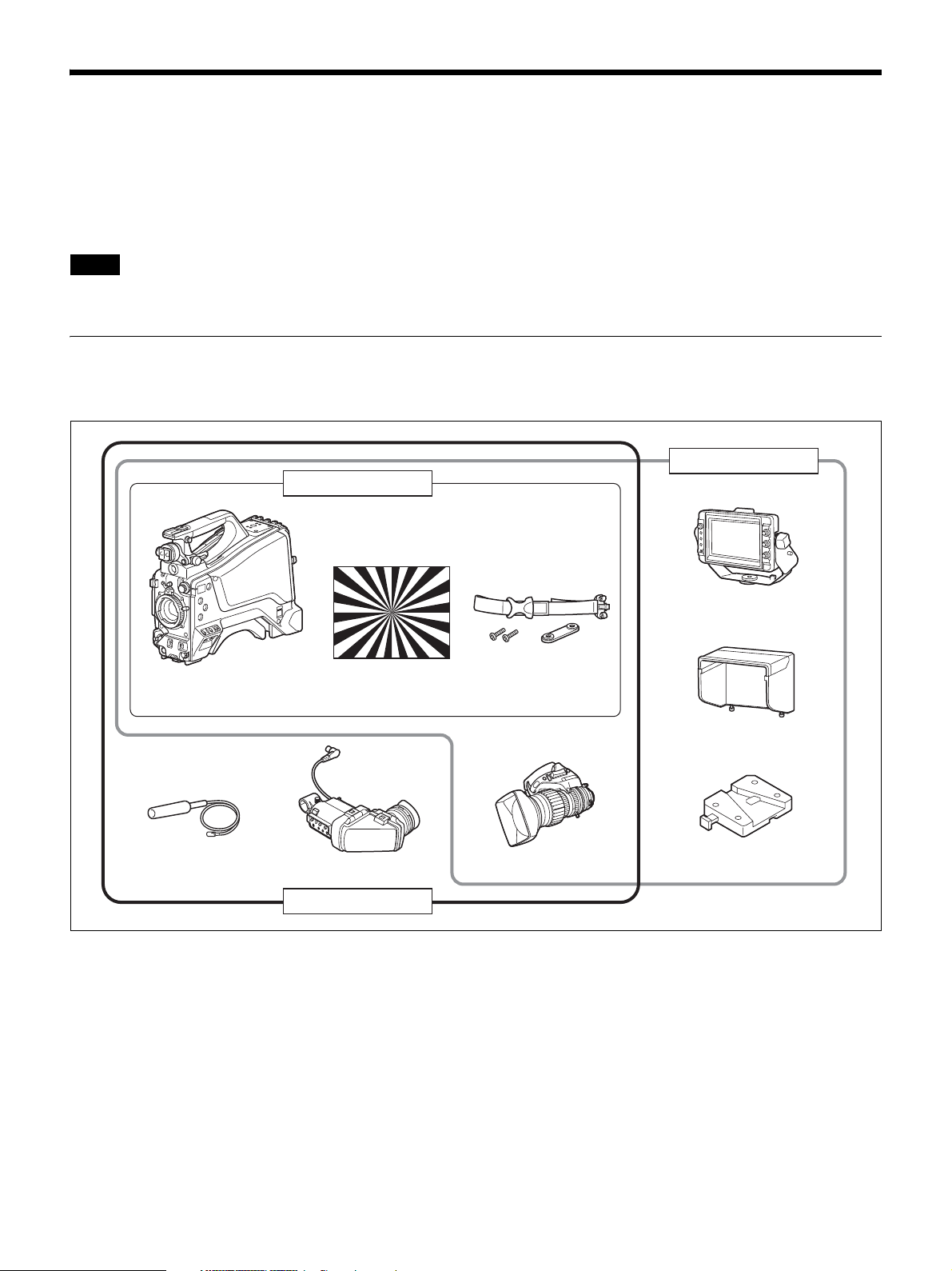
Camera System Components
The HXC-FB80 camera system comprises the components shown in the figure below.
The operation of the camera head is the same for all models.
HXC-FB80S
HXC-FB80H
HXC-FB80 camera head Cable clamp belt
Microphone
Test chart for flange
focal length
adjustment
HDVF-L10
Viewfinder
HXC-FB80K
Lens
HDVF-L750
Viewfinder
Indoor hood
V-wedge shoe
attachment
3
Page 4
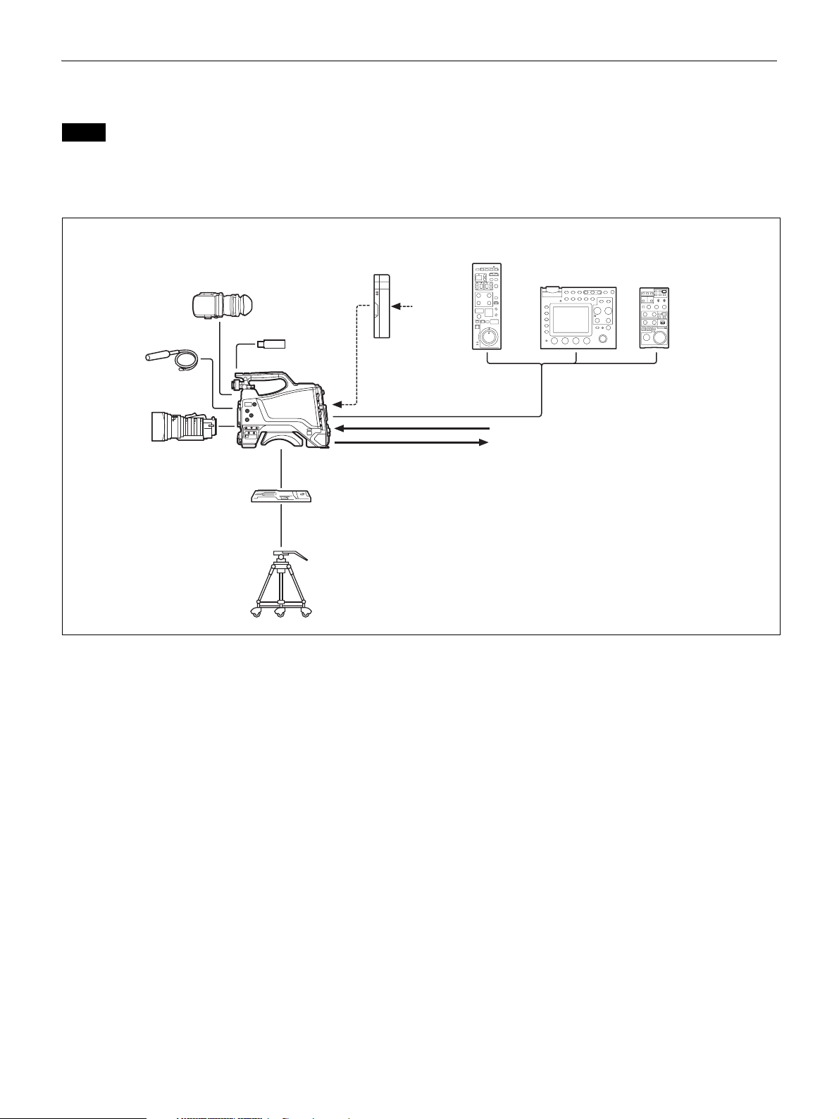
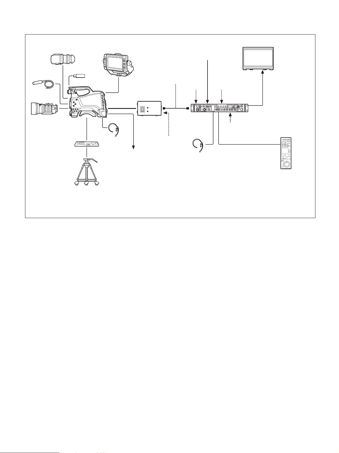
System Configuration
Peripherals and related devices for the camera are shown in the figures.
Note
Production of some of the peripherals and related devices shown in the figures may have been discontinued. For advice on choosing devices, please contact your
Sony dealer or a Sony service representative.
Standalone operation example
RCP-1000 series
Remote Control Panel
RM-B750/B170
Remote Control Unit
AC power
Microphone
HDVF-L10
Viewfinder
AC-DN10
AC Adaptor
USB flash drive
HXC-FB80
Lens
VCT-14/U14
Tripod Adaptor
Tripod for portable
camera
CCA-5 cable
Sync signal input
3G-SDI/HD-SDI/SD-SDI/VBS video output
a) b)
a) No subcarrier phase-lock function with respect to external
reference is available for the VBS signal output from the camera.
b) SD-SDI and VBS output are not available when OUTPUT
FORMAT is set to HDR.
4
Page 5
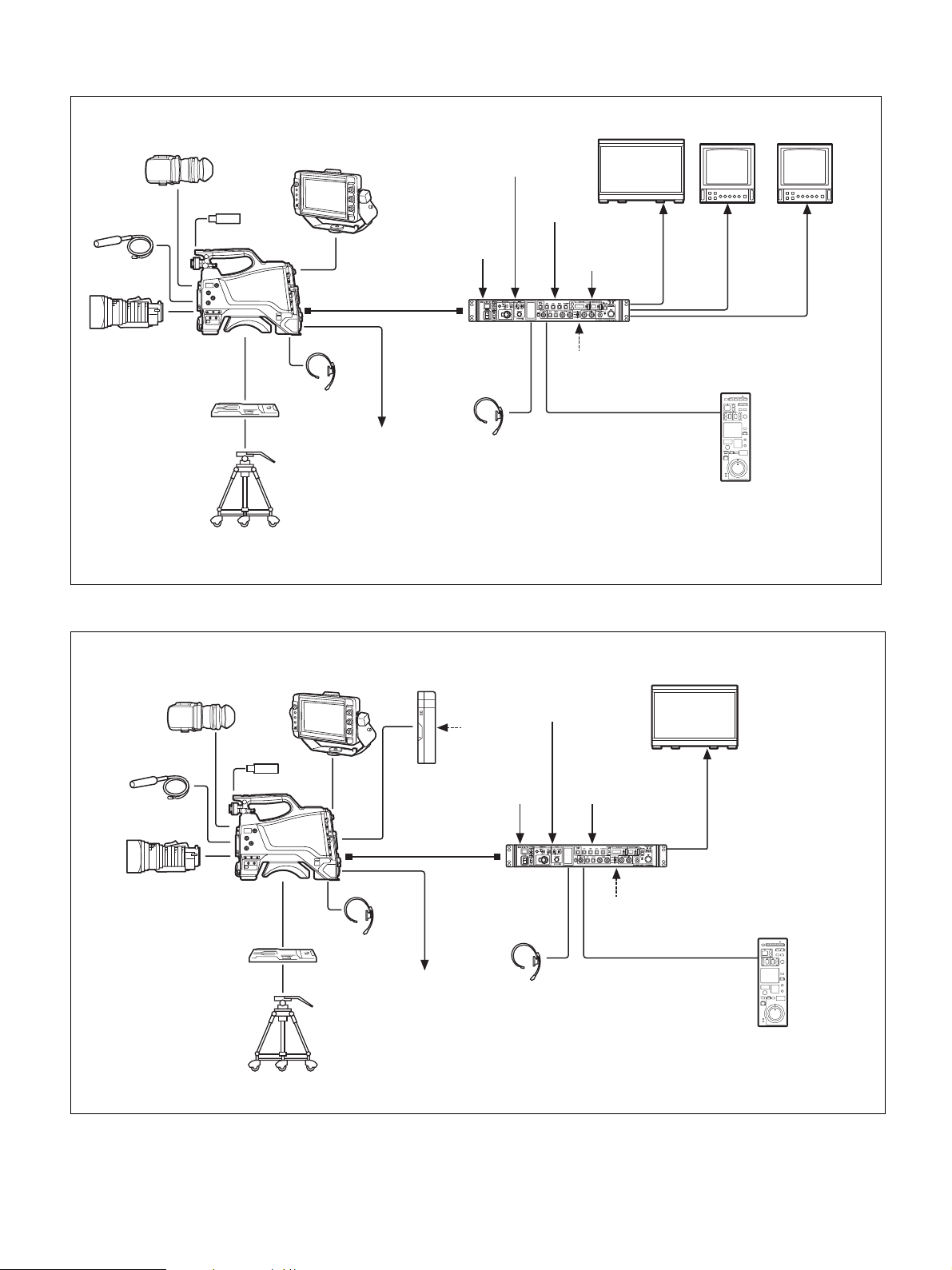
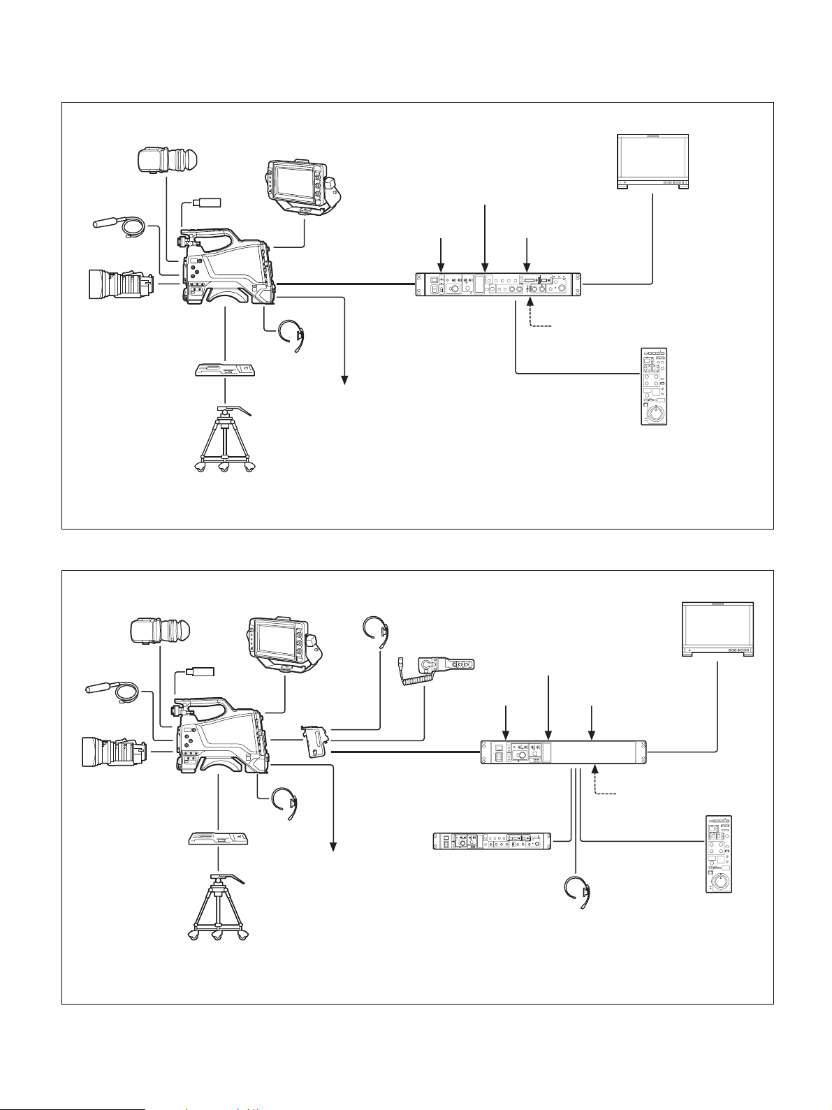
4K SDR and HD SDR signal operation (connection with HXCU-FB80)
Microphone
Lens
VCT-14/U14
Tripod Adaptor
Tripod for portable
camera
HDVF-L10
Viewfinder
USB flash drive
HXC-FB80
Picture
monitor
b)
SLOT1: HD
SDI/SD SDI
video output
HDVF-L750
Viewfinder
Optoelectric
composite cable
Intercom
headset
a)
Prompter video
output
Return video
input
Sync signal
input
HXCU-FB80
4K/HD Camera
Control Unit
Intercom
headset
VBS prompter
video input
HD prompter
video input
AC power
CCA-5 cable/LAN cable
Remote Control Panel
4K compatible
picture monitor
SLOT2: 4K/
12G, 4K/3G,
or 2K/3G
video output
c)
RCP-1000-series
a) The maximum transmission distance is approximately 600 m (1,150 ft) when using Sony CCFN-25/50/100/
150/200/250 Hybrid Fiber Cable (with camera head + portable lens + HDVF-L750).
b) 4K/3G output and 2K/3G output are not supported at the same time.
c) A LAN cable can be used only to connect the RCP-1500/1501/1530. To connect it, power needs to be supplied
via a PoE hub or power needs to be supplied to the EXT DC IN connector of the RCP-1500/1501/1530.
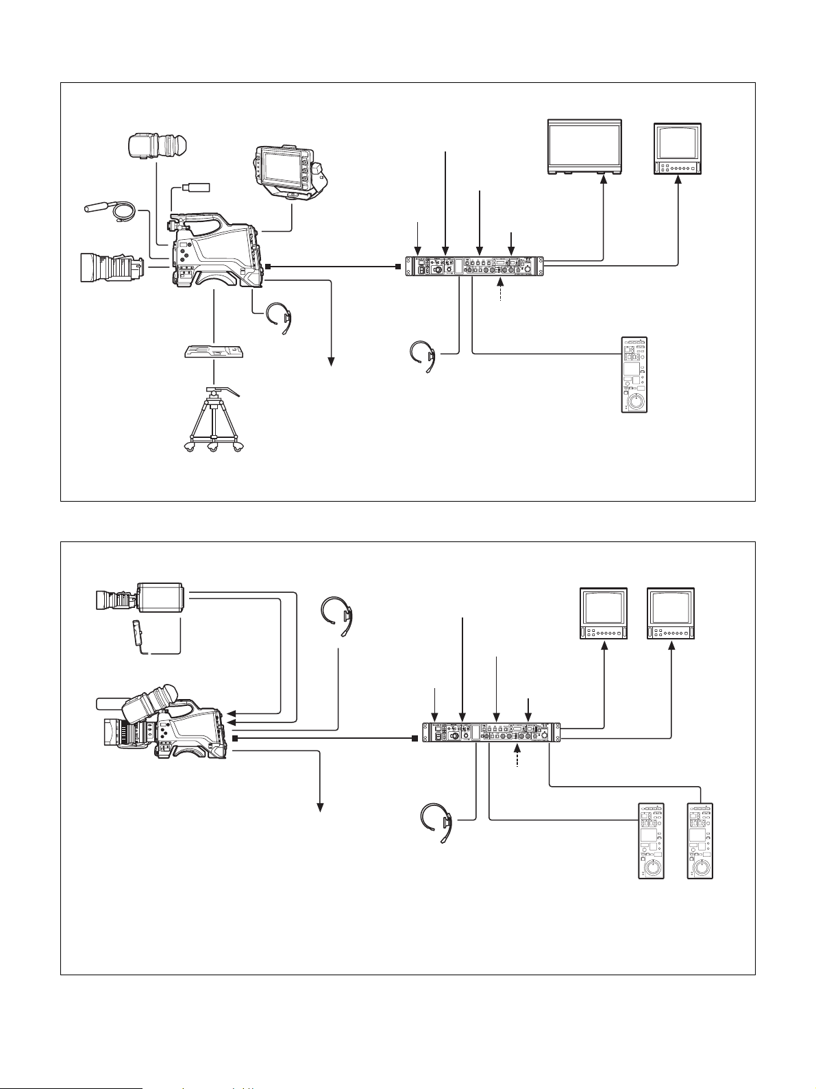
When sub camera is connected (connection with HXCU-FB80)
HXC-P70 etc.
sub camera
AC-DN10
AC Adaptor
HXC-FB80
CCA-5 cable
HD SDI OUT
HD TRUNK
b)
IN
Prompter video output
Intercom
headset
Optical
composite
a)
cable
HXCU-FB80
4K/HD Camera
Control Unit
Return video
input
Sync signal
input
Intercom headset
VBS
prompter
video input
HD prompter
video input
AC power
CCA-5 cable/LAN
cable
Remote Control Panel
c)
a) The maximum transmission distance is 600 m (1,970 ft) when Sony CCFN-25/50/100/150/200/250 Hybrid Fiber Cable is used.
b) Operation supported when the signal format is not set to 1080/50P, 59.94P.
c) LAN cable connection is supported only for RCP-1500/1501/1530. Power must be supplied via a PoE hub or power supply must be connected
to EXT DC IN connector of RCP-1500/1501/1530.
d) For details about a D-Sub remote adapter, contact a Sony service representative.
HD picture
monitor
SLOT2:
HD TRUNK
video
output
D-Sub n 8 pin
RCP-1000-series
b)
monitor
Picture
SLOT1:
HD SDI/
SD SDI video
output
d)
5
Page 6
HD HDR and HD SDR signal operation (connection with HXCU-FB80)
Microphone
Lens
VCT-14/U14
Tripod Adaptor
Tripod for portable
camera
HDVF-L10
Viewfinder
USB flash drive
HXC-FB80
HDVF-L750
Viewfinder
Optoelectric
composite cable
Intercom
headset
a)
Prompter video
output
Return video
input
Sync signal
input
HXCU-FB80
4K/HD Camera
Control Unit
Intercom
headset
HD HDR compatible
picture monitor
VBS
prompter
video input
HD prompter
video input
AC power
CCA-5 cable/LAN cable
Remote Control Panel
SLOT2:
HD HDR
video
output
c)
RCP-1000-series
HD picture
monitor
SLOT2:
HD SDR or
HD TRUNK
video
output
b)
Picture
monitor
SLOT1:
HD SDI/
SD SDI
video
output
a) The maximum transmission distance is approximately 600 m (1,150 ft) when using Sony CCFN-25/50/100/
150/200/250 Hybrid Fiber Cable (with camera head + portable lens + HDVF-L750).
b) HD TRUNK output supported when the signal format is set to 1080/50i HDR, 59.94i HDR.
c) A LAN cable can be used only to connect the RCP-1500/1501/1530. To connect it, power needs to be supplied
via a PoE hub or power needs to be supplied to the EXT DC IN connector of the RCP-1500/1501/1530.
System operation example: When connected using single-mode optical fiber cables
HDVF-L10
Viewfinder
Microphone
Lens
VCT-14/U14
Tripod Adaptor
Tripod for portable
camera
HDVF-L750
Viewfinder
USB flash
drive
HXC-FB80
Intercom
headset
a) The maximum transmission distance is approximately 10 km (6 miles) when using general-purpose
b) A LAN cable can be used only to connect the RCP-1500/1501/1530. To connect it, power needs to be
AC-DN10
AC Adaptor
Single-mode optical
fiber cables (pair)
Prompter video
output
AC power
Sync signal
input
a)
HXCU-FB80
4K/HD Camera
Control Unit
Intercom
headset
Return
video input
VBS prompter
video input
AC power
CCA-5 cable/LAN cable
Picture monitor
Video
output
b)
RCP-1000-series
Remote Control Panel
single-mode fiber cables with LC connectors.
supplied via a PoE hub or power needs to be supplied to the EXT DC IN connector of the RCP-1500/
1501/1530.
6
Page 7
System operation example: When connected with HXCE-FB70 Power Supply Unit
Microphone
Lens
VCT-14/U14
Tripod Adaptor
Tripod for portable
camera
HDVF-L10
Viewfinder
USB flash drive
HXC-FB80
HDVF-L750
Viewfinder
Optoelectric
composite
a)
cable
Intercom
headset
HXCE-FB70
Power Supply
Unit
Prompter video
output
Single-mode
optical fiber
b)
cable
AC power
Return video
input
Sync signal
input
HXCU-FB80
4K/HD Camera
Control Unit
Intercom
headset
VBS prompter
video input
AC power
CCA-5 cable/LAN cable
Picture monitor
Video
output
c)
RCP-1000 series
Remote Control Panel
a) The maximum transmission distance is approximately 350 m (1,150 ft) when using Sony CCFN-25/50/
100/150/200/250 Hybrid Fiber Cable (with camera head + portable lens).
b) The maximum transmission distance is approximately 10 km (6 miles) when using general-purpose
single-mode fiber cables with LC connectors.
c) A LAN cable can be used only to connect the RCP-1500/1501/1530. To connect it, power needs to be
supplied via a PoE hub or power needs to be supplied to the EXT DC IN connector of the RCP-1500/
1501/1530.
7
Page 8
System operation example: When connected using an optoelectric composite cable (connection
with HXCU-FB70)
Microphone
Lens
VCT-14/U14
Tripod Adaptor
Tripod for portable
camera
HDVF-L10
Viewfinder
USB flash drive
HXC-FB80
Picture monitor
HDVF-L750
Viewfinder
Return video input
Prompter video input
AC power
CCA-5 cable /
LAN cable
b)
HD-SDI/SD-SDI/VBS/HDMI
video output
RCP-1000 series
Remote Control Panel
Optoelectric
composite cable
Intercom
headset
Prompter video output
Sync signal input
a)
HXCU-FB70
HD Camera Control Unit
a) The maximum transmission distance is approximately 350 m (1,150 ft) when using Sony CCFN-25/50/100/
150/200/250 Hybrid Fiber Cable (with camera head + portable lens + HDVF-L750).
b) A LAN cable can be used only to connect the RCP-1500/1501/1530. To connect it, power needs to be supplied
via a PoE hub or power needs to be supplied to the EXT DC IN connector of the RCP-1500/1501/1530.
System operation example: When connected using a triaxial cable
HDVF-L10
Viewfinder
USB flash drive
Microphone
Lens
VCT-14/U14
Tripod Adaptor
Tripod for portable
camera
HDVF-L750
Viewfinder
HXC-FB80
Intercom headset
CAC-6
Return Video Selector
Return video input
CA-TX70
HD Camera
Adaptor
Intercom
headset
Prompter video output
Triaxial cable
a)
Sync signal input Prompter video input
HXCU-TX70
HD Camera Control Unit
HKCU-FP2
Front Control Panel
(Attach to front of HXCU-TX70)
a) For details about transmission distance, refer to the operating instructions for the HXCU-TX70 HD Camera
Control Unit.
b) A LAN cable can be used only to connect the RCP-1500/1501/1530. To connect it, power needs to be supplied
via a PoE hub or power needs to be supplied to the EXT DC IN connector of the RCP-1500/1501/1530.
CCA-5 cable /
LAN cable
Intercom headset
Picture monitor
HD-SDI/SD-SDI/VBS
video output
AC power
b)
RCP-1000 series
Remote Control Panel
8
Page 9
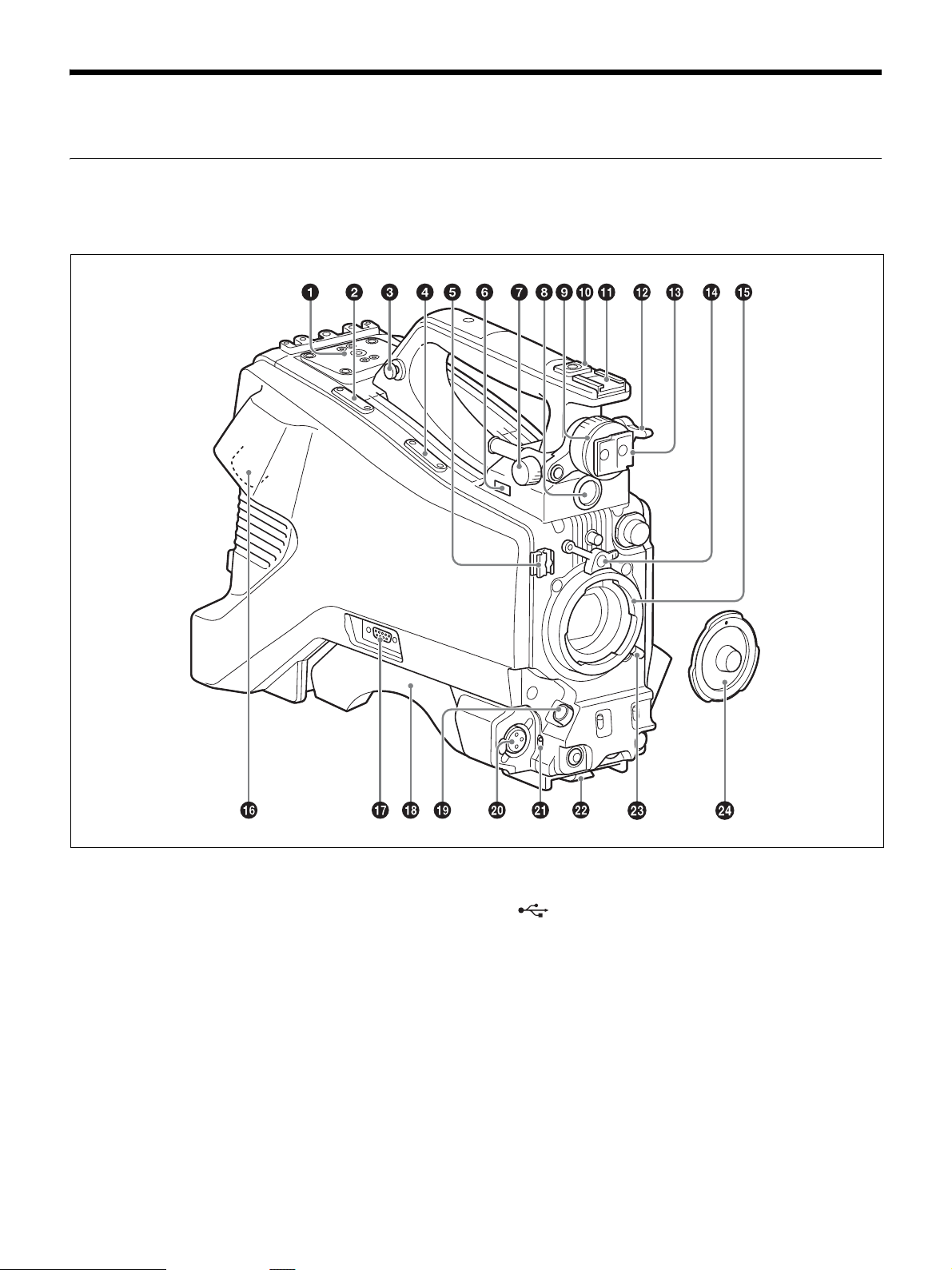
Name and Function of Parts
Front and Left Side
For the pin assignment of each connector, see “Pin Assignment”
(page 68).
a V-wedge shoe attachment
Attach to a HDVF-L750/HDVF-L770/HDVF-EL75 viewfinder. To
attach a viewfinder, attach the V-wedge shoe here.
For details about V-wedge shoe attachment, see “Attaching the VWedge Shoe Attachment” (page 21).
b Cable clamp attachment
For details about attaching, see “Attaching the cable clamp belt”
(page 16).
c Shoulder strap fitting
For details about attaching, see “Attaching the Shoulder Strap”
(page 26).
d Microphone holder attachment
For details about attaching, see “Attaching the microphone holder”
(page 25).
e Cable clamp
Clamp the lens cable and microphone cable.
f (USB) connector
For details about how to use a USB flash drive and compatible USB
flash drives, see “Supported USB Flash Drives” (page 66).
g Viewfinder front-to-back positioning lock knob
Loosen this knob to adjust the front-to-back position of the
viewfinder.
h VF (viewfinder) connector (20-pin, round)
Connect the viewfinder cable.
i Viewfinder left-to-right positioning ring
Adjusts the left-to-right position of the viewfinder attached to the
viewfinder shoe. Loosen the ring to adjust the viewfinder position,
then return the ring to the original position to secure the viewfinder.
9
Page 10

j 1/4-inch screw-type accessory shoe
k Slide-type accessory shoe
l Viewfinder front-to-back positioning lever
Adjusts the front-to-back position of the viewfinder attached to the
viewfinder shoe. Loosen the lever to adjust the viewfinder position,
then return the lever to the original position to secure the viewfinder.
m Viewfinder shoe
Attach the HDVF-L10 viewfinder supplied with the HXC-FB80K.
For details about attaching, see “Attaching and Adjusting the
Viewfinder” (page 18).
n Lens mount securing rubber
After locking the lens in position using the lens locking lever, fit this
rubber over the lower of the two projections. This secures the lens
mount, preventing it from coming loose.
o Lens mount (special bayonet mount)
Attach a lens.
Consult your Sony dealer or a Sony service representative for
information about available lenses.
For details about attaching, see “Attaching and Adjusting the Lens”
(page 23).
p CCU (Camera Control Unit) connector (optoelectric
composite connector)
Connect to the HXCU-FB80 4K/HD Camera Control Unit.
When connected with an optoelectric composite cable, all the
signals of the camera, comprising the power supply, control signals,
video signals, and audio signals, can be transmitted/received with
the one optoelectric composite cable.
When connected with a pair of single-mode fiber cables, all the
signals except the power supply can be transmitted/received with the
pair of single-mode fiber cables.
q TRUNK connector (D-sub 9-pin)
Use as the trunk signal (RS-232C) input/output connector when
connected with the HXCU-FB80.
It features an assignable pin that can be used, when connected using
a dedicated cable, for a function assigned on the <EXT I/O> page in
the MAINTENANCE menu.
r Shoulder pad
Raise the shoulder pad fixing lever to adjust the position in the frontto-rear direction. Adjust the position for maximum convenience
when operating the camera on your shoulder.
For details about adjusting the position, see “Adjusting the Shoulder
Pad Po si tio n” ( page 2 7).
For details about connecting the microphone supplied with the
HXC-FB80K, see “Connecting a microphone to the AUDIO 1 IN
connector” (page 24).
u Audio input 1 selector switch
Select the audio level input to the AUDIO 1 IN connector.
+48V: To supply +48 V phantom power to condenser microphones
MIC: When a microphone-level input is connected
LINE: When a line-level (0 dBu) signal source is connected
Select +48V when using the microphone supplied with the HXCFB80K.
v Trip od mou nt
For details about attaching, see “Mounting on a Tripod” (page 25).
w Lens locking lever
After inserting the lens in the lens mount, rotate the lens mount ring
with this lever to lock the lens in position.
After locking the lens, be sure to use the lens mount securing rubber
to prevent the lens from becoming detached.
x Lens mount cap
Remove by raising the lens locking lever. When no lens is mounted,
keep this cap fitted for protection from dust.
s LENS connector (12-pin)
Connect the lens cable.
Note
When connecting/disconnecting the lens cable, power off the camera first.
t AUDIO 1 IN (audio input 1) connector (XLR type, 3-pin,
female)
Connect to audio equipment or a microphone.
When the camera is connected to an HXCU-FB80, the input signal
will be output from the AUDIO OUTPUT CH-1 connector. You can
configure the camera so that the audio is embedded in the output
from the SDI output (MIC1) on the <SDI OUT> page in the
MAINTENANCE menu.
10
Page 11
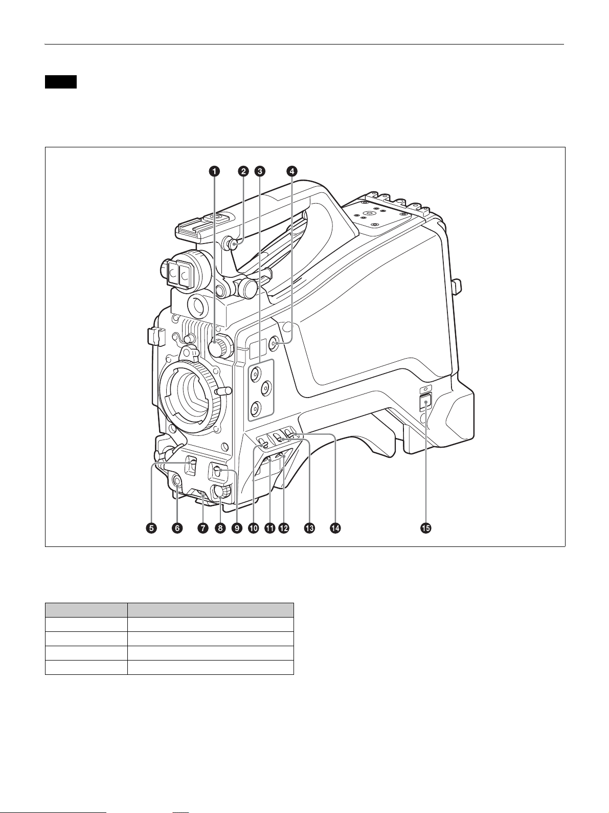
Front and Right Side
Note
When connected to a camera control unit or external remote control device
(for example, RCP or RM), the following switch functions are controlled
from the connected device. The switches on the camera do not function.
• SHUTTER switch
•WHT/BLK switch
• OUTPUT/AUTO KNEE switch
•WHITE BAL switch
• GAIN switch
a FILTER (filter select) knob
Switch between four built-in ND filters. When this switch is
adjusted, the filter setting appears in the viewfinder for about three
seconds.
FILTER knob setting ND filter
1 Clear
2 1/4 ND (attenuates light to approximately 1/4)
3 1/16 ND (attenuates light to approximately 1/16)
4 1/64 ND (attenuates light to approximately 1/64)
b Shoulder strap fitting
For details about attaching, see “Attaching the Shoulder Strap”
(page 26).
c ASSIGN (assignable) 1/2/3 buttons
You can assign functions to these buttons using ASSIGNABLE
1/2/3 on the <SWITCH ASSIGN1> page in the OPERATION menu.
No function is assigned by factory default.
d COLOR TEMP. (color temperature) button
Press the button, turning it on, to change the color temperature for
shooting (factory default: 5600K).
You can assign a function to this button using ASSIGN CTEMP on
the <SWITCH ASSIGN1> page in the OPERATION menu.
e SHUTTER switch
Set to the ON position to use the electronic shutter. Set to the SEL
position to switch the shutter speed or shutter mode display. When
this switch is operated, the shutter settings appear in the viewfinder
for about three seconds.
11
Page 12

f RET (return video) button
Displays the return video signal in the viewfinder while this button
is pressed.
You can assign a function to this button using FRONT RET on the
<SWITCH ASSIGN2> page in the OPERATION menu.
Note
The display image may be distorted when the video signal is switched.
g INTERCOM LEVEL knob
When connected with the HXCU-FB80, use this knob to adjust the
intercom/earphone volume level. The intercom volume level can
also be adjusted using the INTERCOM knob on the rear of the
camera.
When the camera is used in standalone operation mode, use this
knob to set the gain for microphones connected to the AUDIO 1 IN
and AUDIO 2 IN connectors. You can assign a function to this knob
using FRONT VR on the <VR ASSIGN> page in the OPERATION
menu.
h Menu control knob (rotary encoder)
Rotate to select settings from menus displayed in the viewfinder and
press to confirm settings.
i WHT/BLK (automatic white/black balance adjustment)
switch
Automatically adjusts the white balance and black balance.
WHT: Adjust the white balance automatically. If the WHITE BAL
switch is set to A or B, the white balance setting is stored in the
corresponding memory (A or B). If the WHITE BAL switch is
set to PRST, the adjustment function does not operate.
BLK: Adjust the black set and black balance automatically.
You can use the WHT/BLK switch even when the ATW (Auto
Tracing White Balance) function is operating.
If you push the switch to the WHT position once more during
automatic white balance adjustment, the adjustment is canceled and
the white balance setting returns to the original setting.
If you push the switch to the BLK position once more during the
automatic black balance adjustment, the adjustment is canceled and
the black balance setting returns to the original setting.
m OUTPUT (output signal select)/AUTO KNEE switch
Select the signal that is output from the camera.
BARS: Output the color bar signal.
CAM: Output the video signal being shot. When this is selected, you
can switch the AUTO KNEE function
1) AUTO KNEE function:
Against a very bright background with the iris opening adjusted for the
subject, objects in the background will be lost in the glare. The AUTO
KNEE function suppresses areas of high brightness automatically to
reproduce the background more clearly.
This is particularly effective in the following cases.
• Shooting people in the shade on a sunny day
• Shooting a subject indoors, against a background through a window
• Any high contrast scene
1)
ON/OFF.
n WHITE BAL (white balance memory select) switch
Set the white balance adjustment method. When this switch is
adjusted, the new setting appears in the viewfinder for about three
seconds.
PRST: Adjust the color temperature to the preset value (factory
default: 3200K). Use this setting when you have no time to
adjust the white balance.
A or B: Recall the white balance adjustment value already stored in
memory A or B. Push the WHT/BLK switch to the WHT
position to automatically adjust the white balance and save the
adjustment value in memory A or memory B.
o CAMERA POWER switch and indicator
Set to one of the following, according to the power supply method.
CCU: When supplying power from the camera control unit
EXT: When supplying power on the DC IN connector or camera
adaptor power connector
The indicator lights up in green during operation.
j GAIN switch
Switch the gain of the video amplifier to match the lighting
conditions during shooting. When this switch is adjusted, the new
setting appears in the viewfinder for about three seconds.
The gain values corresponding to the L, M, and H settings are
specified using GAIN on the <SWITCH ASSIGN1> page in the
OPERATION menu (factory default: L=0 dB, M=6 dB, and
H=12 dB).
k STATUS/CANCEL switch
STATUS: Displays camera status information when no menu is
displayed and the DISPLAY/MENU switch is set to DISPLAY.
CANCEL: Cancel changed settings or return the display to the
previous menu when a menu is displayed.
l DISPLAY/MENU switch
Select the display in the viewfinder.
DISPLAY: Displays various textual information and markers, such
as messages showing the camera settings and operating status,
the center marker, and the safety zone marker, in addition to the
camera image.
OFF: Displays the camera image only.
MENU: Display the menu, in addition to the camera image.
12
Page 13
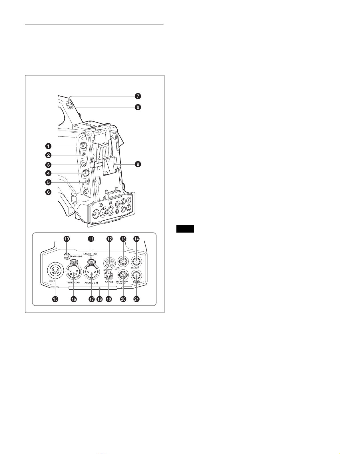
Rear
For the pin assignment of each connector, see “Pin Assignment”
(page 68).
For details about removing the rear cover, see “Removing the rear
cover” (page 17).
(With rear cover removed)
c RET1 (return video 1) button
Displays the return video 1 signal in the viewfinder while this button
is pressed.
d INTERCOM (intercom volume) knob
Adjust the intercom volume level.
When connected with the HXCU-FB80, the intercom volume level
can also be adjusted using the INTERCOM LEVEL knob on the rear
of the camera.
In standalone operation mode, you can assign a function to this knob
using REAR VR on the <VR ASSIGN> page in the OPERATION
menu.
e INTERCOM MIC (intercom microphone) switch
The switch function varies depending on the PANEL TYPE setting
on the <INTERCOM> page in the OPERATION menu (factory
default: CE).
When the PANEL TYPE setting is CE
Functions as the intercom microphone line selector switch.
PROD: Output the microphone on the PROD line.
OFF: Turn the microphone OFF.
ENG: Output the microphone on the ENG line.
When the PANEL TYPE setting is UCJ
Functions as the intercom line and microphone ON/OFF selector
switch.
PROD: Select the PROD line and turn the microphone OFF.
OFF: Select the ENG line and turn the microphone OFF.
ENG: Select the ENG line and turn the microphone ON (output on
ENG line).
You can have a conversation on the selected line while the
assignable button on the rear is pressed by assigning the function
that turns the intercom microphone ON to the button.
a PGM LEVEL (program level) knob/assignable button
Adjust the intercom PGM audio level.
When connected with the HXCU-FB80, this adjusts the PGM audio
level input from the camera control unit.
In standalone operation mode, this adjusts signal level input on the
SDI I/O connector.
No function is assigned to the assignable button by factory default.
You can have a conversation on the intercom line while the button is
pressed by assigning the function that turns the intercom
microphone ON using REAR ENC SW on the <SWITCH
ASSIGN2> page in the OPERATION menu.
b RET2 (return video 2) selector switch
Select the return video signal (2, 3, 4) displayed when the button
assigned with the return video 2 function is pressed.
Note
The intercom and microphone of the camera can be used when connected to
a CA-TX70.
The intercom is connected to the line selected using the INTERCOM switch
of the CA-TX70. ENG/PROD cannot be selected on the camera.
f CALL button
When you press this button, the red tally indicators on the connected
camera control unit and external control device (for example, RCP
or RM) will light up.
g TALLY indicators (red/green)
When the TALLY switch is set to ON, the tally indicator lights up
when a tally signal is input to the connected camera control unit or
a call signal is generated by pressing the CALL button.
h TALLY s wit c h
Set to ON to activate the TALLY indicator function.
i Camera adaptor attachment
Attach an optional CA-TX70 HD Camera Adaptor and AC-DN10
AC Adaptor.
j EARPHONE jack (stereo, minijack)
Monitor the audio output from the intercom or audio signals input to
the AUDIO 1 IN and AUDIO 2 IN connectors.
Set the earphone output on the <EARPHONE> page in the
OPERATION menu.
The earphone volume level can be adjusted using the INTERCOM
LEVEL knob.
k Audio input 2 selector switch
Select the audio level input to the AUDIO 2 IN connector.
13
Page 14
+48V: To supply +48 V phantom power to condenser microphones
MIC: When a microphone-level input is connected
LINE: When a line-level (0 dBu) signal source is connected
l REMOTE (remote control) connector (8-pin)
Connect a remote control unit for remote control the camera.
When used in conjunction with the HXCU-FB80, connect with the
REMOTE connector (8-pin) of the sub camera in order to send the
Sub command.
Note
Before connecting/disconnecting a remote control unit, power off the camera
first.
m TEST OUT connector (BNC type)
Outputs an analog signal.
You can select the VBS signal, Y signal of the VF connector,
HD-SYNC, or SD-SYNC for output in the MAINTENANCE menu.
Note
VBS signal output is not available when HDR is set.
n SDI OUT connector (BNC type)
Outputs a 3G-SDI signal, HD-SDI, or SD-SDI signal.
You can select the output signal in the MAINTENANCE menu.
o DC IN (DC power supply input) connector (XLR 4-pin,
female)
To operate the camera from an external DC power supply, connect
an optional DC power cord to this connector and then connect the
cord to an AC-DN10 AC Adaptor or other source.
You can select the input signal to be displayed in the viewfinder on
the <EXT RETURN> page in the MAINTENANCE menu.
When connected to a CCU, the connector can be used as an HD
PROMPTER output signal connector when set as an output (OUT).
It can be used as an HD TRUNK input signal connector when set as
an input (IN).
Note
Only HD-SDI signals in the same format specified on the <OUTPUT
FORMAT> page in the MAINTENANCE menu can be input on the SDI I/O
connector.
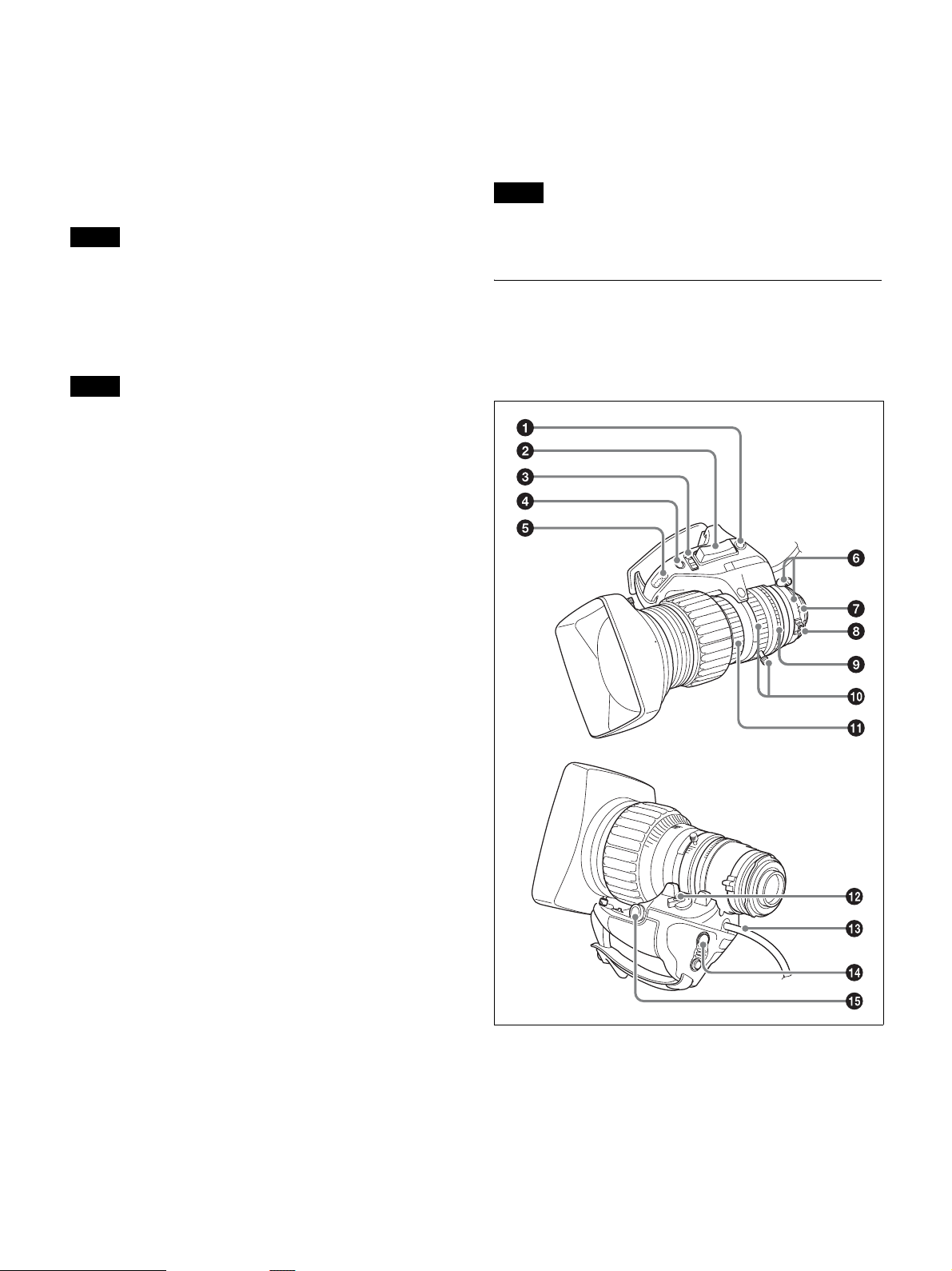
Lens (supplied with the HXC-FB80K/
HXC-FB80S)
For details about attaching a lens, see “Attaching and Adjusting the
Lens” (page 23).
p INTERCOM connector (XLR 5-pin)
Connect an XLR 5-pin headset for input and output of intercom
audio signals.
q AUDIO 2 IN (audio input 2) connector (XLR type, 3-pin,
female)
Connect to audio equipment or a microphone.
When the camera is connected to an HXCU-FB80, the input signal
will be output from the AUDIO OUTPUT CH-2 connector. You can
configure the camera so that the audio is embedded in the output
from the SDI output (MIC2) on the <SDI OUT> page in the
MAINTENANCE menu.
r Tail guard
Protects the cables connected to the connectors on the rear panel.
s DC OUT (DC power supply output) connector (4-pin,
female)
Supplies power to a script light or other device (maximum 1.5 A).
t PROMPTER/GENLOCK (prompter signal output/external
sync signal input) connector (BNC type)
When connected with a CCU, this connector outputs a VBS
prompter signal.
In standalone operation mode, connect an external sync signal (BB
or tri-level sync) for synchronizing the camera. If a VBS signal is
input, you can check the input image in the viewfinder by pressing
the RET button on the camera.
u SDI I/O connector (BNC type)
The input (IN) and output (OUT) mode can be changed using the
menu.
In standalone operation mode, this displays the HD-SDI signal input
on the SDI I/O connector in the viewfinder when the RET button is
pressed.
a RET (return video) button
Displays the return video signal in the viewfinder while this button
is pressed.
b Zoom see-saw switch
This is enabled when the zoom servo/manual selector knob is in the
SERVO position. The zoom speed increases when you push the
switch deeper, and decreases when you push less deeply.
14
Page 15
W (Wide): Wide angle.
T (Telephoto): Telephoto.
c Iris operation mode selector switch
A (Auto): The iris is adjusted automatically.
M (Manual): Adjust the iris with the iris ring.
d Iris one-push auto switch
When the iris operation mode selector switch is in the M position for
manual adjustment, press this switch for instantaneous auto iris
adjustment. The iris is automatically adjusted while the switch is
pressed.
e Iris gain adjustment trimmer
Adjust the iris gain when the iris operation mode selector switch is
in the A (Auto) position.
Flip off the rubber cap, and turn the iris gain adjustment trimmer
using a screwdriver or similar object. Rotate clockwise to increase
the gain, and rotate counterclockwise to decrease the gain.
f F.B. l o c k scr e w/F.B . a djus t m ent r i n g
Use to adjust the flange back (flange focal length).
g Positioning pin
When attaching a lens, align this pin with the slot in the top center
of the lens mount on the camera.
h Macro button/macro ring
Press and hold the macro button and rotate the macro ring to focus
(close-up: 10 mm minimum).
i Iris ring
For manual iris adjustment, set the iris operation mode selector
switch to the M (manual) position, then rotate this ring.
For details about attaching the HDVF-L10 viewfinder, see
“Attaching and Adjusting the Viewfinder” (page 18).
For details about the viewfinder supplied with the HXC-FB80S, refer
to the operation manual for the HDVF-L750.
Note
Always set the iris operation mode selector switch to the M (manual)
position before rotating the ring.
j Zoom lever/zoom ring
For manual zoom adjustment, set the zoom servo/manual selector
switch to the MANU (manual) position, then operate this lever/ring.
k Focus ring
Rotate this ring to adjust the focus.
l Zoom servo/manual selector knob
SERVO: Power (servo) zoom. Control the zoom using the zoom
see-saw switch.
MANU (Manual): Manual zoom. Control the zoom using the zoom
lever/zoom ring.
m Lens cable
Connect to the LENS connector on the camera.
n VTR button
You can assign a function to this button using LENS VTR S/S on the
<SWITCH ASSIGN2> page in the OPERATION menu.
o Zoom remote control connector
Connecting an optional zoom servo controller allows remote control
of zooming.
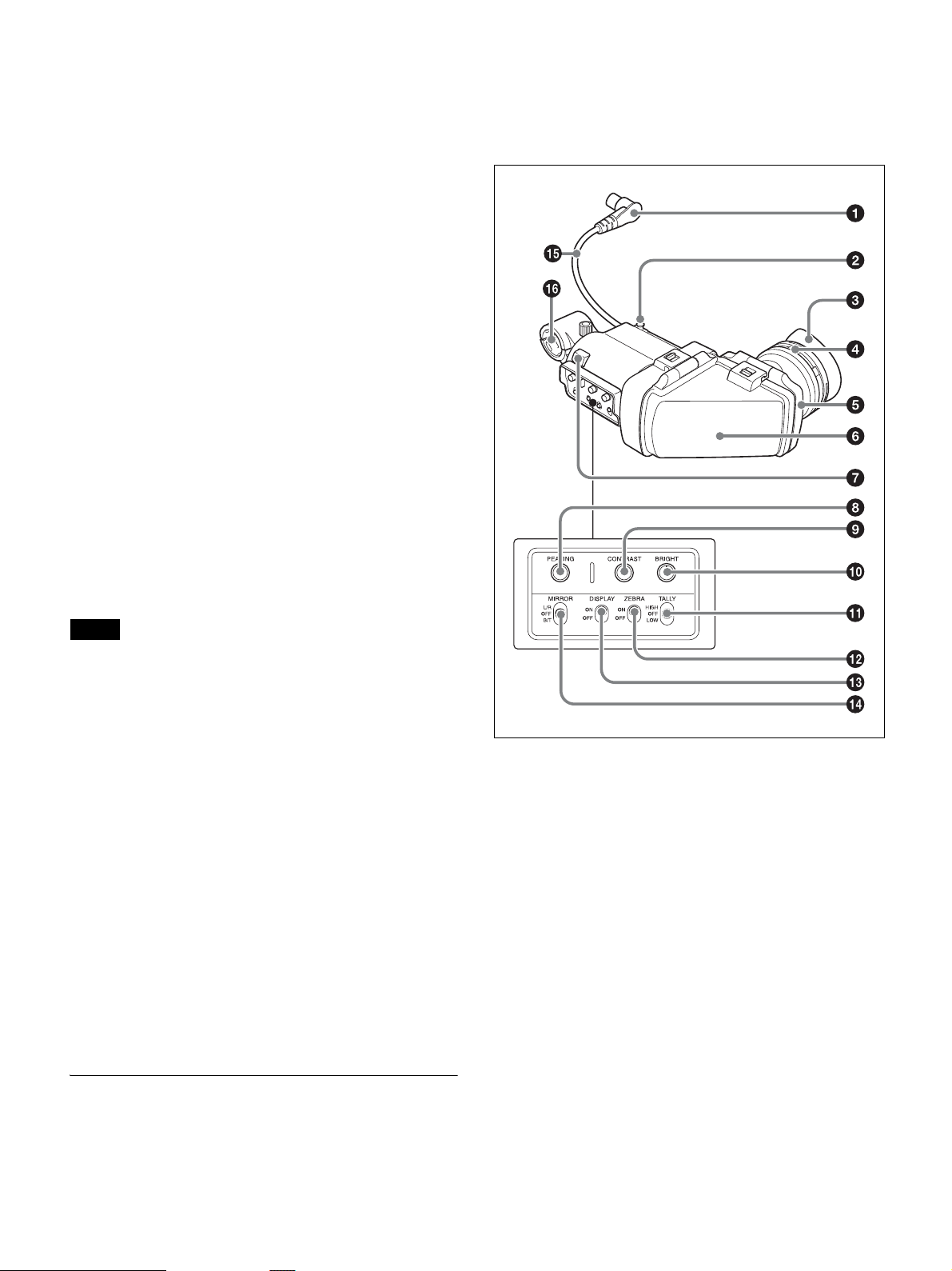
Viewfinder
This section describes the HDVF-L10 viewfinder supplied with the
HXC-FB80K.
a Connector
Connect to the VF connector on the camera.
b Slide stopper
Prevents the viewfinder from coming off the camera when it is slid
from side to side.
c Eyecup
d Diopter adjustment ring
Rotate the ring to adjust the image for clear focus.
e Eyepiece
You can raise the eyepiece or remove it when required by the usage
situation.
f Viewfinder barrel
You can raise the viewfinder barrel or remove it when required by
the usage situation.
g Tally indicator
The indicator lights up when a red tally signal is input to the camera.
When an abnormality occurs, the tally indicator flashes to indicate a
warning.
15
Page 16
h PEAKING knob
Rotate clockwise to adjust the picture sharpness to make lens
focusing easier. This has no effect on the output signal of the camera.
i CONTRAST knob
Adjust the contrast of the screen. This has no effect on the output
signal of the camera.
j BRIGHT knob
Adjust the brightness of the screen. This has no effect on the output
signal of the camera.
k TALLY s wit c h
Used to control the tally indicator on the viewfinder.
HIGH: The tally indicator brightness is set to high.
OFF: The tally indicator is disabled.
LOW: The tally indicator brightness is set to low.
l ZEBRA (zebra pattern) switch
Use to control the zebra pattern display.
ON: Display the zebra pattern.
OFF: Do not display the zebra pattern.
m DISPLAY switch
Use to control the display of text information.
ON: Display text information.
OFF: Do not display text information.
Also used when switching to full-screen display mode or reduced
display mode.
Note
There may be a mismatch between the DISPLAY switch ON/OFF state and
the actual ON/OFF operation, depending on the camera settings.
n MIRROR switch
Used to reverse the image display on the monitor screen horizontally
or vertically when the viewfinder barrel is raised up or rotated.
L/R (left/right): Reverse the image horizontally.
OFF: Do not reverse the image.
B/T (bottom/top): Reverse the image vertically.
Connection and Setup
Connecting to a Camera Control Unit
When operating the camera in a system with a camera control unit
(CCU), connect the CCU connector of the camera and the
CAMERA connector of the CCU using an optoelectric composite
cable.
When required, secure the cable, using the supplied cable clamp
belt.
If connecting an HXCU-TX70 HD Camera Control Unit, refer to the
operating instructions for the HXCU-TX70.
Attaching the cable clamp belt
1 Insert the belt bracket C into hole A or B of the cable
clamp belt.
C
B
A
2 1 Remove the screw-hole cover on the top rear of the
camera and 2 secure the cable clamp belt to the camera
using the two supplied screws (+B3×10).
o Viewfinder cable
p Microphone holder
16
Page 17
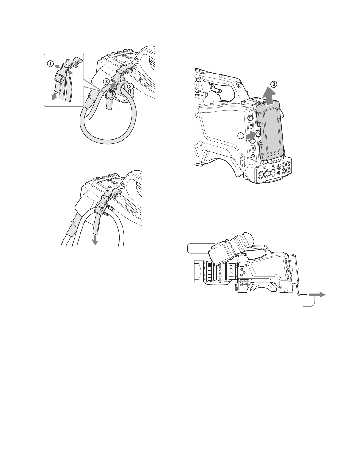
3 1 Release the buckle, 2 bundle the cable with the belt, 3
then close the buckle again.
4 Adjust the length by pulling down on the end of the belt.
If attaching the AC adaptor
Remove the rear cover and attach the AC adaptor to the camera.
Removing the rear cover
1 Hold the release button on the camera in, and 2 pull the rear
cover up.
Attaching the AC adaptor
Attach an optional AC-DN10 AC adaptor to the camera, then
connect to the AC power supply.
The AC-DN10 can supply up to 100 W of power.
AC Power Supply (Standalone
Operation)
Prepare an AC power supply when using the camera in standalone
operation mode (without a CCU).
For safety, use only the Sony AC adaptor listed below.
• AC adaptor: AC-DN10
If using the DC IN connector
Connect the AC-DN10 AC adaptor to the DC IN output connector
on the camera using an optional DC power cord.
To AC outlet
17
Page 18
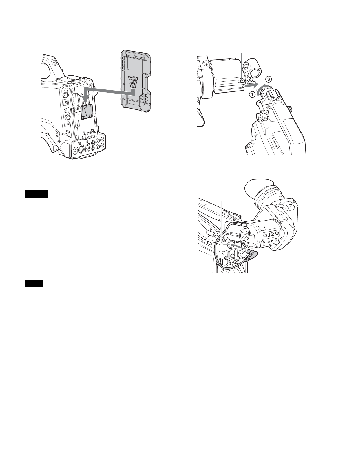
To attach the rear cover
Align the guide on the inner side of the rear cover with the camera
adaptor mount, and insert the cover.
1 1 Loosen the viewfinder left-to-right positioning ring, 2
attach the viewfinder to the viewfinder shoe, and 3 tighten
the viewfinder left-to-right positioning ring.
Slide stopper
Rear cover
Attaching and Adjusting the Viewfinder
Warning
When the viewfinder is attached, do not leave the camera with the
eyepiece facing the sun.
Direct sunlight can enter through the eyepiece, be focused in the
camera and cause a fire.
This section describes how to attach and adjust the HDVF-L10
viewfinder supplied with the HXC-FB80K. For details about
attaching and adjusting the viewfinder supplied with the HXCFB80S, refer to the operation manual for the HDVF-L750.
2
3
1
2 Connect the viewfinder connector to the VF connector.
VF connector
Attaching the viewfinder
Attach the HDVF-L10 viewfinder supplied with the HXC-FB80K.
Notes
• Be sure to power off the camera before plugging the viewfinder connector
into the VF connector of the camera. If the connector is plugged in while
the power is on, the viewfinder may not operate correctly.
• Plug the viewfinder connector all the way into the VF connector of the
camera. If the connector is not firmly connected, the image may become
distorted or the tally indicator may not operate properly.
To detach the viewfinder
Detach in the reverse procedure of attaching. When detaching the
viewfinder from the shoe, lift up the slide stopper on the viewfinder.
18
Page 19
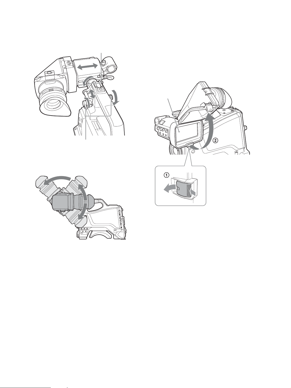
Adjusting the position
To adjust the viewfinder left-to-right position, loosen the left-toright positioning ring. To adjust the front-to-back position, loosen
the front-to-back positioning lever and lock knob.
Viewfinder left-to-right positioning ring
Viewfinder front-to-back positioning lever
and lock knob
Adjusting the angle
You can adjust the angle of the viewfinder.
Raising the viewfinder barrel or eyepiece
You can view the LCD screen inside the viewfinder or its mirrored
image by raising the viewfinder barrel or eyepiece.
This section describes how to raise and detach the viewfinder barrel.
The eyepiece can also be raised and detached in the same way.
To raise the viewfinder barrel
1 Push the clip on the bottom to release it, and 2 flip up the
viewfinder barrel.
It locks at the 120-degree position.
LCD screen
To reverse the display (image/text indication)
vertically
The viewfinder can be rotated as much as 180 degrees so that it is
facing the subject.
In this case, the image and other information displayed appear
upside down on the screen.
To restore the normal display, set the MIRROR switch on the
viewfinder to the B/T position to flip the display vertically.
Keep in the lock position for normal use.
You can also open it farther from the lock position. To set to the 120degree position again, return it to the closed position and then open
it again.
19
Page 20
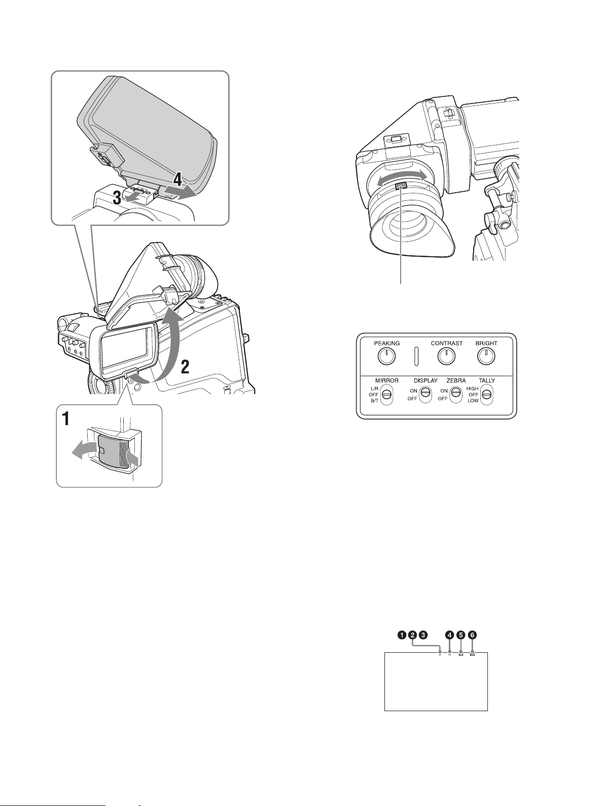
To detach the viewfinder barrel
Adjusting the diopter
Rotate the diopter adjustment ring until the viewfinder image is
sharpest.
Diopter adjustment ring
Adjusting the screen
1 Push the clip on the bottom to release it.
2 Flip up the viewfinder barrel.
3 Slide the button on the top in the direction opposite to the
viewfinder barrel to unlock the barrel.
4 Detach the viewfinder barrel by sliding it horizontally.
To reverse the display (image/text indication)
horizontally
Set the MIRROR switch on the viewfinder to the L/R position to
reverse the picture and other information displayed in the viewfinder
horizontally.
You can adjust the following items.
Peaking: Adjust using the PEAKING knob.
Contrast: Adjust using the CONTRAST knob.
Brightness: Adjust using the BRIGHT knob.
Screen display mode and indicator
The viewfinder screen can be set to full-screen display mode or
reduced display mode.
To switch the display mode, switch the DISPLAY switch “ON t
OFF t ON t OFF” or “OFF t ON t OFF t ON” in quick
succession.
Full-screen display mode
Displays the image so that it fills the full-screen display area.
Tally and other indicators are superimposed on the camera image.
Use this mode when the resolution of the displayed image is more
important.
20
Page 21
Reduced display mode
Displays the camera image at a reduced size, with the tally and other
indicators displayed in the spaces above and below the camera
image.
Use this mode when the clear visibility of the tally and other
indicators is more important.
Indicators are located at the top and bottom of the screen to indicate
the status of the camera and viewfinder.
a G TALLY (green tally) indicator (green)
Lights up when a green tally signal is input.
b R TALLY (red tally) indicator (red)
Lights up when a red tally signal is input.
c Y TALLY (yellow tally) indicator (yellow)
Not supported by the camera.
Note
In full-screen display mode, the display position of the tally indicators is
fixed in one location. Accordingly, only one R/G/Y tally indicator can be lit
at any one time, regardless of the signal that is input. The display priority of
the tally indicator is red, green, and yellow, in that order.
d [!] indicator (amber)
Using the ‘!’ IND function, the ‘!’ indicator appears when nonstandard settings are in effect.
Attaching the V-Wedge Shoe
Attachment
To attach the HDVF-L750 Viewfinder supplied with the HXCFB80S or an optional HDVF-L770/HDVF-EL75, connect the Vwedge shoe attachment supplied with the camera or viewfinder to
the camera and then attach the viewfinder to the attachment.
The procedure for attaching the attachment is given below.
For details about attaching a viewfinder, refer to the operation
manual for the viewfinder.
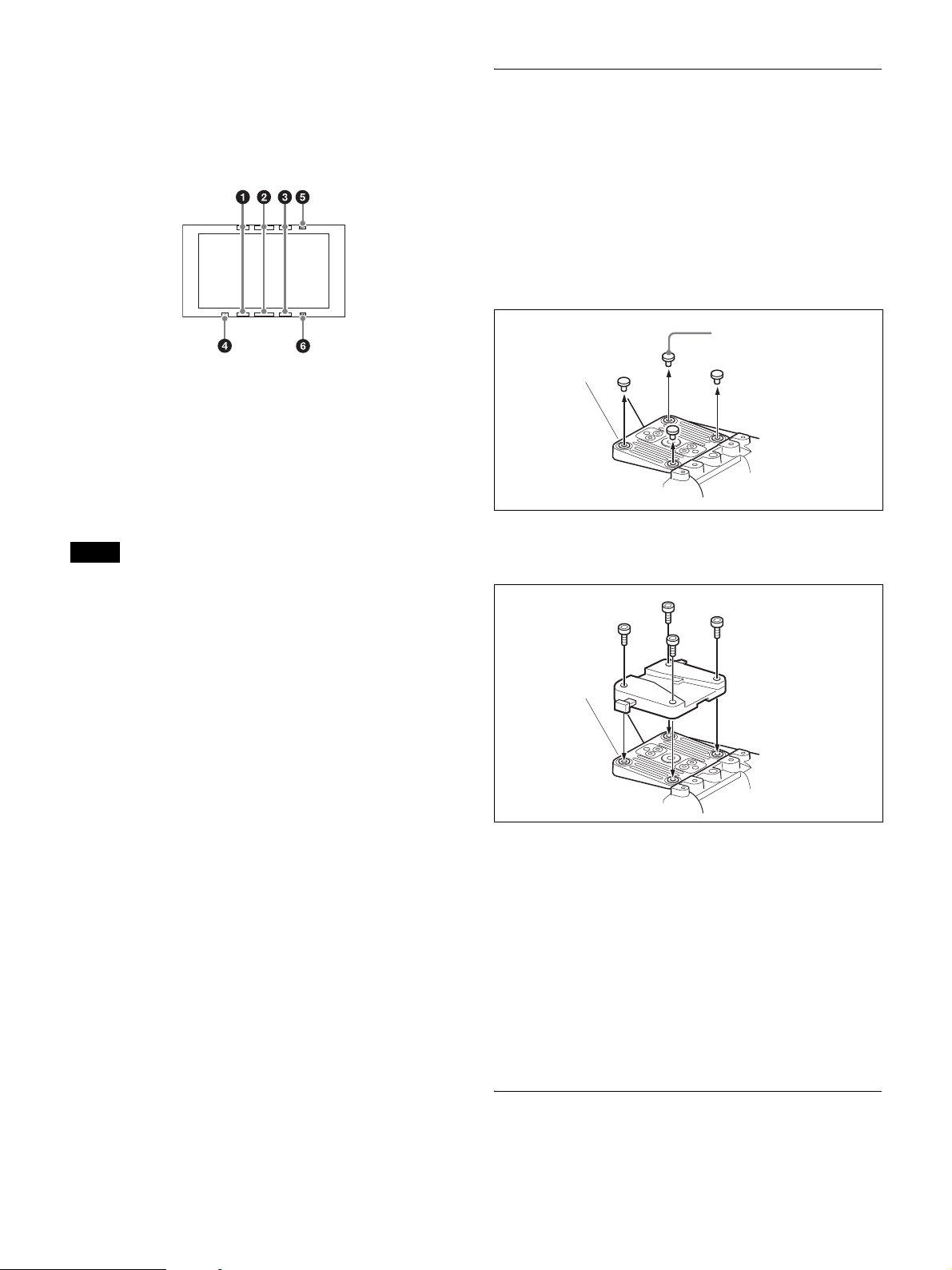
1 Remove the four plastic caps from the camera.
Plastic caps
2 Attach the V-wedge show attachment (supplied) to the
camera using the hex wrench (supplied) and four hex socket
bolts (4×12, supplied).
e BATT (battery) indicator (red)
Lights up or flashes to indicate the status of the power supply to the
camera.
Lit: Significant voltage decrease
Flashing: Voltage decrease
f SAVE indicator (amber)
Not supported by the camera.
3 Insert the viewfinder firmly into the V-wedge shoe
attachment.
A click sound occurs when properly attached.
Front-to-back position adjustment (when
HDVF-L770 or HDVF-EL75 is attached)
To attach an HDVF-L770 LCD Color Viewfinder or HDVF-EL75
HD Electronic Viewfinder, move the mount wedge on the bottom of
the viewfinder 15 mm toward the camera operator from the default
position.
For details about attaching, refer to the operation manual for the
viewfinder.
Using the Camera for the First Time
The camera is shipped with the area of use setting in an unset state.
To use the camera, you need to first set the area of use.
21
Page 22
Once the area setting is complete, set the current date and time.
Note
The camera cannot be used if the area of use is not set.
Setting the area of use
To change the area of use
Change the setting using COUNTRY on the <OUTPUT FORMAT>
page in the MAINTENANCE menu.
Note
The setting is switched to the CCU setting when a CCU is connected.
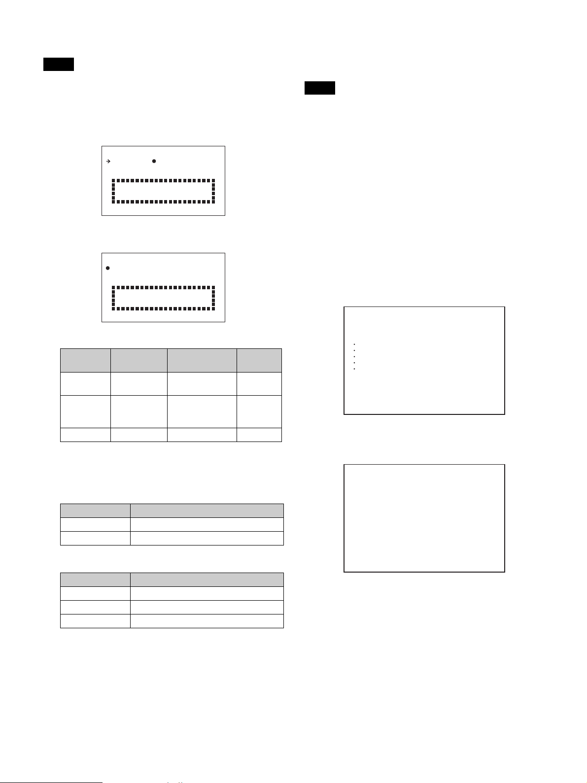
1 Turn on the camera.
The screen for setting the area of use appears in the viewfinder.
FO MAT SE TT I NG
C O U N T RRY: NOT SELECT
SYSTEM L I NAE:108
SYSTEM SC N: Inter lace
SET FORMAT
AND TURN OFF ONCE .
ED
0
2 Press the menu control knob.
The area of use becomes selectable.
FO MA T SET T I NG
C O U N T RRY: NOT SELECT
SYSTEM L I NAE:108
SYSTEM SC N: I n t e r l a ce
SET FORMAT
AND TURN OFF ONCE .
?
ED
0
3 Rotate the menu control knob to select the area of use.
Setting Area of use Output composite
NTSC(J)
AREA
NTSC AREA NTSC area (for
PAL A REA PAL a re a PAL s ig n al 50i
NTSC area
(Japan)
areas other than
Japan)
signal
NTSC signal
without setup
NTSC signal with
setup (7.5IRE)
System
frequency
59.94i
59.94i
4 Change the SYSTEM LINE (video resolution) and
SYSTEM SCAN (video scanning mode) settings according
to the video format you are using.
SYSTEM LINE
Setting Resolution (Horizontal × Vertical)
1080 1080 lines (1920×1080)
720 720 lines (1280×720)
SYSTEM SCAN
Setting Video scanning mode
Interlace Interlaced
Progressive Progressive
PsF Progressive
Supported formats: 1080/59.94i, 1080/59.94P, 1080/50i,
1080/50P, 1080/29.97PsF, 1080/25PsF, 1080/23.98PsF,
720/59.94P, 720/50P
Setting the date/time
Set the built-in clock to the current local time on the <DATE> page
in the MAINTENANCE menu.
For details about menu operations, see “Menu Operation”
(page 34).
1 Turn on the camera.
2 Press and hold the menu control knob and set the
DISPLAY/MENU switch to MENU.
The camera enters menu mode, and “TOP” is displayed at the
upper-right corner of the screen.
3 Rotate the menu control knob to align the , pointer with
TOP and press the menu control knob.
The TOP MENU screen is displayed.
<TOP MENU>
c
USER
USER MENU CUSTOMIZE
ALL
OPERATION
PAINT
MAINTENANCE
FILE
DIAGNOSIS
4 Rotate the menu control knob to align the , pointer with
MAINTENANCE and press the menu control knob.
The CONTENTS page of the MAINTENANCE menu appears.
CONTENTS M00 TOP
xx
c
01.<AUTO SETUP>
02.<WHITE SHADING>
03.<BLACK SHADING>
04.<AUTO IRIS>
05.<LENS>
06.<CIS COMP>
07.<AUDIO>
08.<CALL/TALLY>
09.<OUTPUT FORMAT>
10.<TEST OUT>
11.<SDI OUT>
12.<TRUNK>
13.<GENLOCK>
14.<DATE>
5 Rotate the menu control knob to scroll the page and align
the , pointer with <DATE> and press the menu control
knob.
The <DATE> page appears.
Press the menu control knob to confirm the page selection.
5 Turn the camera off and then back on.
The camera is now ready for use.
22
Page 23

<DATE> M14 TOP
DATE/TIME
x
2016/04/30 08:32
FILE TIMESTAMP FORMAT
: 5 M/D/Y
6 Set the date and time items.
Rotate the menu control knob to select an item, and press the
menu control knob.
Rotate the menu control knob to change the setting of the
selected item, and press the menu control knob to confirm the
setting.
7 When finished, set the DISPLAY/MENU switch to OFF to
exit menu mode.
Attaching and Adjusting the Lens
For information on handling lenses, refer to the operation manual
for the particular lens.
Lens mount
securing rubber
Attaching the lens
Note
Before attaching the lens, power off the camera first.
1 Push the lens locking lever up and remove the lens mount
cap from the lens mount.
2 Align the center pin on the lens with the center slot in the
lens mount, and insert the lens into the mount.
3 Holding the lens in place, push the lens locking lever down
to lock the lens.
Caution
If the lens is not firmly locked, it may come off while the
camera is being used. This could cause a serious accident.
Make sure the lens is firmly locked. It is recommended that the
lens mount securing rubber be put on the lens locking lever as
illustrated above.
4 Connect the lens cable to the LENS connector.
5 Secure the lens cable with the cable clamps.
23
Page 24

When attaching an aberration correction lens
The aberration correction function is activated automatically.
Starting the camera with an aberration correction lens may require
more time than normal because of data loading at start-up.
The lens supplied with the HXC-FB80K/HXC-FB80S is an
aberration correction lens. Contact your Sony dealer or a Sony
service representative for information about other aberration
correction lenses.
Adjusting the flange back (flange focal length)
If the lens does not stay in focus properly as you zoom from
telephoto to wide angle, adjust the flange focal length (the distance
from the plane of the lens mounting flange to the imaging plane).
This adjustment is required once only after attaching or changing the
lens.
When carrying out the adjustment, use the supplied flange focal
length adjustment chart as the subject.
9 Tighten the F.B. lock screw.
Preparing the Audio Input
Connecting a microphone to the AUDIO 1 IN
connector
Attach the microphone supplied with the HXC-FB80K to the
microphone holder on the viewfinder.
1 1 Loosen the screw and 2 open the microphone holder
clamp.
Microphone holder clamp
Approx. 3 m (10 ft)
Notes
• If you use a subject with insufficient contrast, or move the camera or
subject during adjustment, this will cause an adjustment error.
• Place the subject (the flange focal length adjustment chart) so that it
appears at the center of the screen at the telephoto end. Arrange so that no
nearby object (no object closer to the camera than the chart) enters the
screen at the wide-angle end.
1 Set the iris to manual, and open the iris.
2 Position the supplied flange focal length adjustment chart
approximately 3 m (10 ft) away from the camera, and
arrange the lighting to obtain a satisfactory video output.
3 Loosen the F.B. (flange back) lock ring.
4 Use manual or servo zoom to set the lens to telephoto.
5 Point the camera at the flange focal length adjustment chart
and rotate the focus ring to focus the image.
2 Place the microphone in the microphone holder.
1 Place the microphone in the holder so that “UP” is at the
top.
2 Close the microphone holder.
3 Tighten the screw.
6 Set the zoom ring to wide angle.
7 Rotate the F.B. adjustment ring to focus on the chart.
Take care not to move the focus ring.
8 Repeat steps 4 to 7 until the chart stays in focus all the way
from wide angle to telephoto.
24
Page 25

3 Connect the microphone cable to the AUDIO 1 IN
connector, and secure with the cable clamp.
Cable clamp
Attaching the microphone holder
1 Remove the screw hole cover from the microphone holder
attachment.
4 Set the audio input 1 selector switch to match the type of
microphone used.
Microphone not requiring a phantom power supply
from the camera:
Set to MIC.
Microphone requiring a phantom power supply from
the camera:
Set to +48V. Select +48V when using the microphone supplied
with the HXC-FB80K.
Note
The AUDIO 1 IN and AUDIO 2 IN connectors on the camera are
female XLR connectors (3-pin) used to provide a phantom 48 V power
supply. If the microphone cable has a female connector, use an adaptor.
5 Switch the input level to match the sensitivity of the
microphone used.
The input level in standalone operation mode can be adjusted
using the <AUDIO> page setting (factory default: 60 dB) in the
MAINTENANCE menu or by assigning the function on the
<VR ASSIGN> page in the OPERATION menu.
Note
If the input level on the camera is not at an appropriate setting for the
microphone sensitivity, loud sounds may be distorted, and the signalto-noise ratio may be affected.
2 Attach the CAC-12 microphone holder and secure to the
camera using the two supplied screws (+B4×8).
Mounting on a Tripod
Mount the camera on a tripod, using the optional VCT-U14 or VCT14 Tripod Adaptor.
Notes
• If camera instability still affects shooting when using a tripod with the
VCT-U14 Tripod Adaptor, use the VCT-14 Tripod Adaptor for
professional use.
• Select an appropriate hole from among those at the bottom of the tripod
adaptor, considering the balance of the weight of the camera and the tripod
adaptor. If an inappropriate hole is selected, the center of gravity may
cause the camera to fall over, resulting in injury.
• Check that the size of the selected hole matches that of the screw of the
tripod. If they do not match, the tripod adaptor cannot be attached to the
tripod securely.
1 Attach the VCT-14/U14 Tripod Adaptor to the camera
platform.
Tripod adaptor
Connecting a microphone to the AUDIO 2 IN
connector
You can connect a monaural microphone to the AUDIO 2 IN
connector, using an optional CAC-12 microphone holder.
For details about attaching the microphone, refer to the operation
manual for the microphone.
For details about setting the audio input 2 selector switch and input
level of the AUDIO 2 IN connector, see steps 4 and 5 in “Connecting
a microphone to the AUDIO 1 IN connector” (page 24).
Camera platform
25
Page 26

2 Place the camera on the tripod adaptor and slide it forward
along the groove of the platform until it clicks into place.
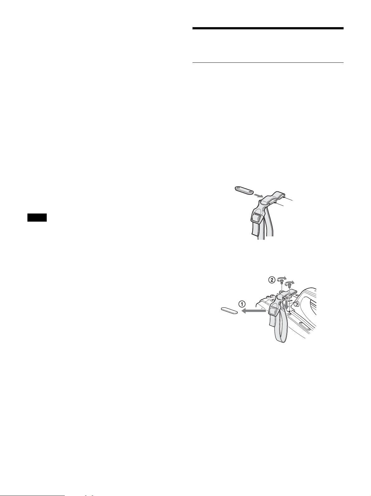
Attaching the Shoulder Strap
Attach an optional shoulder strap (part number: A-6772-374-C) to
the camera.
1 Fit one of the clips to the shoulder strap fitting.
Pull up the strap to secure it in place.
3 Move the camera back and forth, and check that it is
securely fixed.
To remove the camera from the tripod adaptor
Hold down the red button and pull the lever in the direction of the
arrow.
Red button
Lever
If the pin of the tripod adaptor does not return to its
original position
After removing the camera, if the pin of the tripod adapter does not
return to its original position (storage position), hold down the red
button and move the lever in the direction of the arrow to return the
pin to its original position. It is not possible to mount a camera if the
pin remains in the center.
Pin storage position
Pin
Clip
2 Fit the other clip to the shoulder strap fitting on the other
side of the grip.
To remove the shoulder strap
Press here and pull in the direction shown by the arrow.
26
Page 27

Adjusting the Shoulder Pad Position
You can slide the shoulder pad forward and backward within a
40 mm (1
balance for shooting with the camera on your shoulder.
5
/8 inch) range. This adjustment helps you get the best
Lever
Shoulder pad
1 Raise the lever in the center of the shoulder pad to unlock
the shoulder pad.
2 Slide the shoulder pad backward or forward until it is in the
most convenient position.
3 Lower the lever to lock the shoulder pad.
Shooting
Basic Procedure for Shooting
1 Turn the camera on.
2 Set the FILTER knob and COLOR TEMP. button
appropriately for the lighting conditions.
Filter settings
FILTER knob Lighting conditions
1 (Clear) Indoor shooting
2 (1/4 ND) Outdoor (cloudy or rainy) or indoor shooting
when you wish to reduce the depth of field
3 (1/16 ND) Outdoor shooting in daytime
4 (1/64 ND) Outdoor shooting when you wish to reduce the
depth of field, or especially under bright outdoor
ambient light
a) Depth of field: This is the range over which the subject is sharply in
focus. If the range is narrow, the depth of field is called “shallow
focus.” If the range is wide, the depth of field is called “deep focus.”
From the viewpoint of the characteristics of lenses, shooting
with an F-stop value in the range of F4 to F8 is generally
recommended for good quality pictures. Set the FILTER knob
to bring the iris setting into that range. However, this may not
apply when special composition is desired.
5600K setting
The 5600K ON/OFF function is assigned to the COLOR
TEMP. button by factory default.
5600K Lighting conditions
OFF Indoor shooting under lighting with lower color
temperature, such as a halogen or tungsten lamp
ON Outdoor shooting in daytime, or indoor shooting
under lighting with higher color temperature
a)
.
3 Check the settings of the camera.
• Settings of switches/knobs
• Settings in the OPERATION menu (see page 46) and the
PAIN T me n u (see page 53)
• Electronic shutter setting (see page 30)
• Settings for the output signals from the camera (see page 32)
• Flange focal length adjustment (see page 24)
4 Adjust the viewfinder diopter, as well as the contrast and
brightness of the viewfinder image (see page 18).
For details about the operation of optional viewfinders, refer to
the operation manual for the viewfinder.
27
Page 28

5 If required, switch on the center marker, safety zone, and
zebra pattern display in the viewfinder.
Configure in the following menu items.
•<VF MARKER> page (see page 47) in the OPERATION
menu
• <ZEBRA> page (see page 48) in the OPERATION menu
Adjustments and Settings
6 Check the microphone connection and the audio input
selector switch settings (see page 24).
7 Adjust the white balance and black balance (see page 28).
8 Rotate the focus ring on the lens to adjust the focus.
For details about menu operations, see “Menu Operation”
(page 34).
Changing the Video Format
1 Select the <OUTPUT FORMAT> page in the
MAINTENANCE menu.
2 Select the desired format in CURRENT.
Adjusting the Black Balance and White
Balance
To ensure excellent image quality when using this camera,
conditions may require that both the black balance and the white
balance be adjusted.
Black balance and white balance adjustment values that are
automatically set by the camera and other various settings are stored
in the camera memory and retained when the power is turned off.
Note
When connected to a camera control unit or external control device (for
example, RCP or RM), the black balance and white balance adjustment
functions are controlled from the connected device. They are not controlled
using the camera.
For details about operations on the external control device, refer to
the operating instructions or operation manual for the device.
Black balance adjustment
The black balance will require adjustment in the following cases.
• When using the camera for the first time
• When the camera has not been used for a long time
• When the camera is used under conditions in which the
surrounding temperature has changed greatly
• When the gain values configured for the GAIN switch (L/M/H)
have been changed using GAIN on the <SWITCH ASSIGN1>
page in the OPERATION menu.
It is not usually necessary to adjust the black balance when using the
camera after it has been turned off.
White balance adjustment
Always readjust the white balance when the lighting conditions
change.
Adjusting the black balance
In automatic black balance mode, adjustments are performed in the
following order: black set and black balance. Manual black balance
adjustment can be selected in the menu.
For details about manual black balance adjustment, contact a Sony
service representative.
1 Set the OUTPUT/AUTO KNEE switch to CAM.
28
Page 29

2 Push the WHT/BLK switch to the BLK position and release
the switch.
The message “ABB: EXECUTING” appears during execution,
and changes to “ABB: OK” when the adjustment finishes.
Adjustment values are saved in memory automatically.
Notes
• During the black balance adjustment, the iris is automatically shielded.
• During the black balance adjustment, the gain selection circuit is
automatically activated so you may see flicker in the viewfinder, but this
is not a fault.
5 Push the WHT/BLK switch to the WHT position and
release the switch.
If automatic black balance adjustment cannot be
made
If the black balance adjustment cannot be completed normally, an
error message will appear for about three seconds in the viewfinder.
If an error message is displayed, retry the black balance adjustment.
If the error message occurs again, consult your Sony dealer or a
Sony service representative.
Note
If the lens cable is not firmly connected to the LENS connector, it may not
be possible to adjust the lens iris. If this happens, the black balance will be
incorrect.
Adjusting the white balance
1 Set the switches as shown below.
• GAIN switch: L (set to a gain value that is as small as
possible)
• OUTPUT/AUTO KNEE switch: CAM
• WHITE BAL switch: A or B
2 Set the FILTER knob to suit the lighting conditions.
3 Place a white test card under the same lighting conditions
as for the subject to be shot and zoom up to it.
Alternatively, any white object such as a cloth or a wall can be
used.
The minimum required white area is as follows.
Rectangle centered on the screen.
The lengths of the sides are 70% of the length and width
of the screen.
WHT/BLK switch
The message “AWB: EXECUTING” appears during execution,
and changes to “AWB: OK” when the adjustment finishes.
The adjustment values are saved automatically in the memory
selected in step 1 (A or B).
Note
If the camera has a zoom lens with an automatic iris, the iris may hunt 1)
during the adjustment. To prevent this, adjust the iris gain knob (labeled
IG, IS, or S) on the lens.
1) Hunting: Repeated brightening and darkening of the image, resulting
from repeated response to automatic iris control.
For details, refer to the operation manual supplied with the
lens.
If the automatic white balance adjustment cannot
be made
If the white balance adjustment cannot be completed normally, an
error message will appear for about three seconds in the viewfinder.
If an error message is displayed, retry the white balance adjustment.
If the error message occurs again, consult your Sony dealer or a
Sony service representative.
If you have no time to adjust the white balance
Set the WHITE BAL switch to PRST.
The white balance can be set to 5600K automatically by pressing the
COLOR TEMP. button.
You can set the color temperature to 3200K, 4300K, 5600K, or
6300K by assigning the electrical CC filter function to the COLOR
TEMP. button.
The white object must be within the rectangle and have an area
of at least 10% of the screen.
Note
Make sure there are no bright spots in the rectangle.
4 Adjust the lens iris.
Manually adjustable lens: Set the iris to an appropriate
setting.
Lens with automatic iris: Set the iris automatic/manual
switch on the lens to automatic.
To switch the electrical CC filter
You can assign the electrical CC filter switching function to the
ASSIGN 1/2/3 buttons or the COLOR TEMP. button. This allows
you to switch between color temperatures (3200K/4300K/5600K/
6300K) configured for the four positions (A to D) selected with each
press of the button.
1 Select the <WHITE FILTER> page in the
MAINTENANCE menu.
2 Select the position to which to assign a CC filter
(ELECTRICAL CC <A> to <D>).
3 Set the color temperature (3200K, 4300K, 5600K, or
6300K).
To set no color temperature
You can disable ELECTRICAL CC <C> and <D> by setting
the value to “-----.”
29
Page 30

For example, if one position is disabled, then that position is not
displayed and the button switches between the remaining three
positions.
4 Repeat steps 2 and 3 as required.
5 Assign the CC filter switching function (ELECTRICAL
CC) to a button on the <SWITCH ASSIGN1> page in the
OPERATION menu.
For the ASSIGN 1/2/3 buttons, select ASSIGNABLE 1/2/3 and
set to ELECTRICAL CC. For the COLOR TEMP. button,
select ASSIGN CTEMP and set to ELECTRICAL CC.
White balance memory
There are two white balance memories: A and B. When you execute
automatic white balance adjustment, the adjusted white balance
value is stored in the memory (A or B) selected with the WHITE
BAL switch.
The white balance values stored in memory are retained until the
white balance is adjusted again, including when power is turned off.
When power is turned on again, the white balance in memory
corresponding to the current WHITE BAL switch setting is loaded.
Setting the Electronic Shutter
Note
When connected to a camera control unit or external control device (for
example, RCP or RM), the electronic shutter settings are controlled from the
connected device. They are not controlled using the camera.
For details about operations on the external control device, refer to
the operating instructions or operation manual for the device.
Shutter modes
The shutter modes that can be used with the electronic shutter and
the shutter speeds that can be selected are listed below.
Standard mode
Select this mode for shooting fast-moving subjects with little
blurring.
SYSTEM LINE System frequency Shutter speed (Hz)
1080 59.94i 60.00 to 4300
59.94P 59.96 to 4600
50i 50.00 to 4700
50P 50.03 to 4600
29.97PsF 30.00 to 2700
25PsF 25.00 to 2300
23.98PsF 24.00 to 2200
720 59.94P 59.96 to 4600
50P 50.03 to 4600
SLS (Slow Shutter) mode
Select this mode to shoot dimly lit subjects.
You can set the number of accumulated frames to 2, 3, 4, 5, 6, 7, or
8 frames.
Note
In SLS mode, the following limitations apply to automatic functions.
Y: Available, N: Not available
Function Operation in SLS mode
2F 3F/4F/5F/6F/7F/8F
AUTO WHITE Y Y
AUTO BLACK Y 2F setting
AUTO WHITE SHADING N N
AUTO BLACK SHADIN G N N
AUTO LEVEL N N
AUTO HUE N N
AUTO IRIS Y Y
AT W Y Y
AUTO KNEE Y Y
FLARE Y Y
D.EXT Y Y
TLCS (AUTO SHUTTER) Last enabled function takes
precedence
System frequency Shutter speed (sec.)
• 59.94i
• 59.94P
• 50i
• 50P
• 29.97PsF 1/40, 1/60, 1/100, 1/120, 1/125, 1/250, 1/500,
• 25PsF 1/33, 1/50, 1/100, 1/125, 1/250, 1/500, 1/1000,
• 23.98PsF 1/32, 1/48, 1/96, 1/100, 1/125, 1/250, 1/500,
1/100, 1/125, 1/250, 1/500, 1/1000, 1/2000
1/60, 1/125, 1/250, 1/500, 1/1000, 1/2000
1/1000, 1/2000
1/2000
1/1000, 1/2000
ECS (Extended Clear Scan) mode
Select this mode for obtaining images with no horizontal bands of
noise when shooting subjects such as monitor screens.
Setting the shutter mode and shutter speed
Notes
• When automatic iris is used, the iris opens wider as the shutter speed
increases, reducing the depth of field.
• The selectable shutter speeds vary depending on the current system
frequency.
Setting the shutter mode and standard mode
shutter speed
Once the shutter speed is selected, it is retained even when the
camera power is turned off.
1 Push the SHUTTER switch from ON to SEL.
The current shutter setting indication appears in the viewfinder
for about three seconds.
Example: SHUTTER: 1/250
2 Before the shutter setting indication disappears, push the
SHUTTER switch to SEL again.
30
Page 31

Repeat this operation until the desired speed is displayed.
To set ECS mode, select “ECS.” To set SLS mode, select
“SLS.”
All modes and speeds are displayed in the following order.
Example: System frequency of 59.94i
Standard mode
The TLCS function can be assigned to one of the ASSIGN 1/2/3
buttons, and turned on/off by pressing the button.
The effective auto control range is set as shown in the following
diagram on the <TLCS> in the OPERATION menu.
1/100
1/5001/2501/125
1/1000
ECS modeSLS mode
1/2000
To set the shutter speed in ECS mode
1 Set the shutter mode to ECS.
2 Rotate the menu control knob and set the desired
frequency.
To set the shutter speed in SLS mode
1 Set the shutter mode to SLS.
2 Rotate the menu control knob and set the desired number
of frames.
Setting Automatic Iris
The automatic iris setting may need to be changed, according to the
subject lighting conditions, to aid the shooting of clear pictures of
back-lit subjects or to prevent blown-out highlights of subjects
illuminated with spotlights.
The reference value for the lens iris can be set within the range –99
(equivalent to closing the iris by 2 stops) to 99 (equivalent to
opening the iris by 2 stops) with respect to the standard value.
You can monitor the current reference value using the F-stop value
indicator displayed in the viewfinder.
Also, you can set the auto iris target range.
Changing the reference value
The changed reference value is retained until the power of the
camera is turned off. Even if the reference value is changed, it
reverts to the original value every time the power is turned on.
1 Select the <AUTO IRIS> page in the MAINTENANCE
menu.
2 Select AUTO IRIS and set to ON.
3 Select OVERRIDE and set the reference value.
Bright Subject Dark
Iris closed Iris openAuto iris
Restores auto iris control if
the LIMIT value is exceeded.
Notes
• Both AUTO SHUTTER and AGC switch on/off in response to the button
assigned with the TLCS function. You can turn them on/off individually
on the <TLCS> page in the OPERATION menu.
• SLS mode and AUTO SHUTTER cannot be used at the same time. The
last enabled function takes precedence.
Restores auto iris control if
the LIMIT value is exceeded.
Setting the Focus Assist Function
The assist functions for easier focus adjustment can be displayed in
the viewfinder.
Adding the viewfinder detail signal
Adding a detail signal to sharp edges in the image in the viewfinder
makes it easier to check the focus condition by observing changes in
the detail signal or in the color converted from the detail signal
(color detail).
The focus setting where the detail signal becomes strongest is the
best focus setting.
1 Select the <VF DETAIL> page in the OPERATION menu.
<VF DETAIL> c 04 TOP
VF DETAIL : ON 8%
CRISP : 0
FREQUENCY : 9M
FLICKER : OFF
AREA : 100%
ZOOM LINK : ON 100%
COLOR DETAIL : OFF BLUE
PEAK COLOR : OFF
CHROMA LEVEL: 25%
RETURN DISABLE : OFF
Note
Check that the current shutter mode is not ECS before proceeding.
Setting the TLCS Function
You can maintain the proper exposure by using the TLCS (Total
Level Control System) function. This function controls not only the
iris, but also the shutter (AUTO SHUTTER) and gain (AGC: Auto
Gain Control) automatically.
2 To use the VF detail signal, select VF DETAIL and set to
ON.
Set VF DETAIL to ON to activate the VF detail function to add
the detail signal to sharp edges in the image. You can adjust the
level in the range of 0% to 100% (factory default: 8%).
You can adjust the characteristics of the added detail signal with
the menu items below.
CRISP: Eliminate fine portions of the detail signal.
FREQUENCY: Change the detection band of sharp edges.
31
Page 32

FLICKER: Set the function for flickering the detail signal to
ON/OFF. (Setting the function to ON makes it easier to
check the detail signal on the viewfinder screen.)
AREA: Limit the area where to display the detail signal.
ZOOM LINK: Set the VF detail level at the full WIDE position.
(The VF detail level changes according to the zoom
position. The default setting is no change at the 100%
WIDE position, and half at 50%.)
1) Normally, the value is automatically set to the optimum value in
conjunction with the AREA MARKER SIZE set value. Use this
setting when an optimum sensitivity value cannot be obtained,
depending on the shooting environment.
2) Normally, the optimum offset is automatically set in conjunction
with the AREA MARKER SIZE and MASTER GAIN set values.
Use this setting when the optimum offset cannot be obtained,
depending on the shooting environment.
3 To use color detail, select COLOR DETAIL and set to ON.
Setting COLOR DETAIL to ON converts the VF detail signal
to a color. The display color can be selected in the column next
to ON.
You can adjust how color is added with the menu items below.
PEAK COLOR: Turn the function to change the color where
the detail signal is strongest on/off.
CHROMA LEVEL: Reduce the chroma components of the
video signal.
Displaying the focus assist indicators
The focus assist indicator function extracts the irregularities of a
subject and converts the integrated values to a level indicator for
display in the viewfinder.
Level indicator (display position and operation can
be adjusted)
Area marker to display the detection area of the focus
(size and position can be adjusted)
The focus setting where the indicator shows the maximum level is
the best focus setting. (The width of the indicator substantially
changes depending on the picture content and shooting
environment. Adjust using GAIN and OFFSET, as required.)
1 Select the <FOCUS ASSIST> page in the OPERATION
menu.
<FOCUS ASSIST> c 05 TOP
INDICATOR : OFF
MODE : BOX BTM
LEVEL : 40% QUICK
GAIN : 50
OFFSET : 50
AREA MARKER: OFF
SIZE : MIDDLE
POSITION : CENTER
POSITION H: 50
POSITION V: 50
2 To use a level indicator, select INDICATOR and set to ON.
Setting INDICATOR to ON displays the level indicator for
focusing on the monitor.
You can set the display method with the menu items below.
MODE: Set the type and display position of the indicator.
LEVEL: Set the density and the response speed of the indicator.
GAIN: Set the sensitivity of the indicator.
OFFSET: Set the offset of the focus detection value.
1)
2)
3 To use an area marker, select AREA MARKER and set
to ON.
Setting AREA MARKER to ON displays an area marker
indicating the focus detection area on the monitor.
You can set the size and position of the detection area with the
menu items below.
SIZE: Change the size of the detection area. (If the detection
area size is too large, both the subject and the background
are included in the area, making the indicator display
deviate from the subject.)
POSITION: Roughly set the position of the detection area.
POSITION H: Fine adjustment of the position of the detection
area in the horizontal direction.
POSITION V: Fine adjustment of the position of the detection
area in the vertical direction.
Notes
• The level indicator and effect area marker cannot be displayed at the same
time. The one that was set to ON last takes precedence.
• The area marker and aspect safety marker cannot be displayed at the same
time. The one that was set to ON last takes precedence.
• When displaying the focus assist indicators, check that the flange focal
length (flange back) has been precisely adjusted (see page 24).
Setting the Camera Outputs
You can specify video signals directly output from the camera using
the menu.
Note
The MAIN (camera picture), RET (return video), or VF (the same picture as
that displayed in the viewfinder) settings are common to SD-SDI and VBS.
Different signals cannot be output.
The menu pages used for the output settings are registered in the
USER menu by factory default.
• <SDI OUT> (U17)
•<TEST OUT> (U16)
For details about the USER menu, see “Editing the USER Menu”
(page 37).
Set the items on each page as follows.
Outputting the signal being shot (camera picture)
The same textual information as that displayed in the viewfinder can
be added to the output signal by setting CHARACTER to ON on the
<SDI OUT> or <TEST OUT> page.
To output as HD-SDI
Menu page Page No. Item Setting
<SDI OUT> M11 SDI OUT MAIN
32
Page 33

To output as SD-SDI
Menu page Page No. Item Setting
<SDI OUT> M11 SDI OUT SD-SDI
DOWN
CONVERTER
SELECT
Note
SD-SDI output is not available when HDR is set.
MAIN
To output as VBS
Menu page Page No. Item Setting
<TEST OUT> M10 OUTPUT VBS
DOWN
CONVERTER
SELECT
Note
VBS signal output is not available when HDR is set.
MAIN
Constantly outputting a return video
• When a CCU is connected, one of the signals being supplied to the
CCU can be output from the camera.
• The last selected return signal is output.
To output as HD-SDI
Menu page Page No. Item Setting
<SDI OUT> M11 SDI OUT RET
Outputting the same image as that in the viewfinder
With HD-SDI, you can obtain a signal that includes the same
information as that being displayed in the viewfinder according to
the settings for VF MARKER, CHARACTER, VF DETAIL,
ZEBRA, etc. The individual ON/OFF and other settings for adding
information are common to those for the viewfinder. The output is
synchronized with the switching of Y, R, G, B, or return signal in the
viewfinder.
To output as HD-SDI
Menu page Page No. Item Setting
<SDI OUT> M11 SDI OUT VF
panel connected to the CCU or the CONFIGURATION menu on the
CCU.
When the audio input selector switch is set to MIC, the level can be
adjusted between 20 dB and 60 dB in steps of 10 dB.
When the audio input selector switch is set to LINE, the level cannot
be adjusted.
In standalone operation mode
The input level from audio sources connected to the AUDIO 1 IN
and AUDIO 2 IN connectors can be adjusted using the INTERCOM
LEVEL knob on the front of the camera.
When the audio input selector switch is set to MIC, the level can be
adjusted between 20 dB and 60 dB in steps of 10 dB.
When the audio input selector switch is set to LINE, the level cannot
be adjusted.
Set the gain to avoid clipping the audio signal by monitoring the
audio level meters and waveforms.
You can assign a function to the INTERCOM LEVEL knob on the
<VR ASSIGN> page in the OPERATION menu.
Setting the Digital Extender Function
The central area of the screen can be magnified by a factor of 2 or 4
by enabling the digital extender function.
To use the digital extender function, assign the function to one of the
ASSIGN 1/2/3 buttons. Press the button to magnify the central area
of the screen by a factor of 2 or 4, and press again to return to the
original image.
1 Select D.EXT ENABLE on the <OTHERS> page in the
MAINTENANCE menu, and set to ENABLE.
2 Assign the digital extender function (D.EXTENDER ×2 or
×4) to a button on the <SWITCH ASSIGN1> page in the
OPERATION menu.
Select one of ASSIGNABLE 1/2/3, and set to D.EXTENDER
×2 (2×) or D.EXTENDER ×4 (4×).
Note
When D.EXT ENABLE is set to ENABLE on the <OTHERS> page in the
MAINTENANCE menu, video output from the camera is delayed by 1 field.
To output as TEST OUT
Menu page Page No. Item Setting
<TEST OUT> M10 OUTPUT VF
Outputting a prompter signal
The VBS signal supplied to the PROMPTER connector of the CCU
is output from the PROMPTER/GENLOCK connector of the
camera.
Adjusting the Audio Level
When the HXCU-FB80 is connected
The input levels from audio sources connected to the AUDIO 1 IN
and AUDIO 2 IN connectors can be adjusted using a remote control
33
Page 34

Menu Operation
The menus displayed in the viewfinder enable various settings of the
camera.
The following switches are used to operate the menus.
Rotate the menu control knob to select menu items or values, and
press it to register (enter) the selection.
DISPLAY/MENU
switch
STATUS/CANCEL switch
Menu control knob
Rotate to select Press to confirm
Viewfinder Display Screen
Besides the video image, the viewfinder can display text and
messages showing the camera settings and operation status, as well
as items such as a center marker or safety-zone marker.
When the DISPLAY/MENU switch is set to
DISPLAY
Items set to ON using the menu or related switches will be
displayed.
c EX (lens extender) indicator
Displayed when using a lens extender.
d Zoom position indicator
Indicates the approximate position of the zoom lens variator
between wide angle (0) and telephoto (99).
e ! indicator
Displayed when non-standard settings are configured, using the
‘!’ IND function.
f Focus position indicator
Displays the focus position of a zoom lens as a numeric value (0 to
255 (∞)).
g Voltage indicator
Displays the voltage supplied to the camera.
h DIAG indicator
Displays self-diagnostic information.
i Message area
Displays various types of messages.
j 5600K mode indicator
Displayed when the 5600K setting is ON.
k Filter indicator
Displays the type of ND filter (A to D).
l ECC indicator
Displays the type of built-in electrical CC filter (A to D).
m White balance memory indicator
Displays the white balance automatic adjustment memory. This is
not displayed when a CCU is connected.
W:A: The WHITE BAL switch is set to A.
W:B: The WHITE BAL switch is set to B.
W:P: The WHITE BAL switch is set to PRST.
n Gain value indicator
Displays the video gain value (dB) set with the GAIN switch.
o Shutter/ECS indicator
Displays the shutter/ECS setting. Not displayed if the shutter is OFF.
p Audio level meters
Displays the audio levels input to the AUDIO 1 IN and AUDIO 2 IN
connectors.
q Return video indicator
Displayed while the RET button is pressed.
EX Z 99 !
D.EX 12.0
TALK CAM
5600
1 A W: A 12dB ECS
1
2
F 2
RET1
5
a TALK i ndi ca tor
Displayed when the intercom microphone is ON.
b D.EX indicator
Displayed when the digital extender function is ON.
CL
5
V
?
r F-stop value indicator
Displays the lens F-stop (iris opening) value.
When the STATUS/CANCEL switch is set to
STATUS
The status display appears when you set the STATUS/CANCEL
switch to STATUS with the DISPLAY/MENU switch set to
DISPLAY.
The status screen displays the video format and non-standard
settings of the camera.
34
Page 35

1080-59.94i
ASSIGNABLE1 :OFF
ASSIGNABLE2 :OFF
ASSIGNABLE3 :OFF
ASSIGN CTEMP :5600K
!ND :2
!WHITE :P
!5600K :ON
!SHUTT :1/1000
!FAN :MAX
!FORMAT :1080-29.97PsF
OPT LV CAM: b
CCU: b
TRUNK IF :232c
a Format indicator
Displays the current video format.
b Assignable button function indicators
Displays the functions assigned to the ASSIGN 1/2/3 buttons and
COLOR TEMP. button.
For details, see “<SWITCH ASSIGN1>” (page 50) in the
OPERATION menu.
c ‘!’ indicator area
This area is used to display non-standard status, using the ‘!’ IND
function. Display options can be set using the menu.
For details, see “<‘!’ IND>” (page 47) in the OPERATION menu.
d Optical level indicators
Displays the optical levels using multi-segment indicators.
CAM: Optical level on the CCU connector of the camera
CCU: Optical level on the CAMERA connector of the CCU
e TRUNK IF
Displays the TRUNK IF setting status.
Menu Function
USER This menu is user defined and can include often-used
USER MENU
CUSTOMIZE
ALL This menu permits you to control all items of the
OPERATION
(page 46)
PA IN T (page 53) This menu contains items for making detailed image
MAINTENANCE
(page 57)
FILE (page 62) This menu is for performing file operations, such as
DIAGNOSIS
(page 63)
menu pages selected from among the OPERATION,
PAINT, MAINTENANCE, FILE, and DIAGNOSIS
menus. The factory default configuration can be
changed using the USER MENU CUSTOMIZE
menu.
This menu allows you to edit the USER menu.
For details, see “Editing the USER Menu” (page 37).
OPERATION menu, PAINT menu, MAINTENANCE
menu, FILE menu, and DIAGNOSIS menu as a single
menu.
This menu contains items for camera operators to
operate the camera. It mainly permits viewfinder,
intercom, and switch settings.
adjustments while using a waveform monitor to
monitor the waveforms output from the camera.
Support of a video engineer is usually required to use
this menu.
Although you can also use an external control device
to set the items in this menu, the menu is effective
when using the camera outdoors in standalone
operation mode.
This menu contains items for performing camera
maintenance operations and for setting infrequently
used “paint” items.
writing or clearing the reference file.
This menu displays self-diagnostic information.
Operating the Menu
To display a menu page
Set the DISPLAY/MENU switch to MENU.
The menu page last accessed will be displayed. If it is the first time,
the CONTENTS page of the USER menu will be displayed.
To display the TOP MENU screen
If you set the DISPLAY/MENU switch to MENU while holding the
menu control knob pressed, “TOP” is displayed at the upper right
corner of the screen.
Rotate the menu control knob to move the , pointer on the display
to “TOP” and press the menu control knob to display the TOP
MENU screen, listing the available menus.
<TOP MENU>
c
USER
USER MENU CUSTOMIZE
ALL
OPERATION
PAINT
MAINTENANCE
FILE
DIAGNOSIS
To disable the “TOP” indication
Turn the power off then on again, or set the DISPLAY/MENU
switch from OFF to MENU while holding the STATUS/CANCEL
switch in the CANCEL position. This disables the TOP selection.
To select a menu on the TOP MENU screen
Rotate the menu control knob to align the , pointer with the
desired menu and press the menu control knob.
The CONTENTS page (page No. 00) or the last accessed page of the
selected menu is displayed.
35
Page 36

Selecting a Page
Setting Menu Items
To select a page from the CONTENTS page
Rotate the menu control knob to align the , pointer with the
desired page and press the menu control knob.
If the screen can be scrolled, arrows will indicate
the direction for scrolling.
CONTENTS P00 TOP
xx
01.<SW STATUS>
02.<VIDEO LEVEL>
, pointer
03.<COLOR TEMP>
c
04.<GAMMA>
05.<BLACK GAMMA>
06.<SATURATION>
07.<KNEE>
08.<WHITE CLIP>
09.<DETAIL 1>
10.<DETAIL 2>
11.<SD DETAIL>
12.<SD CROSSCOLOR>
13.<SKIN DETAIL>
14.<USER MATRIX>
The selected page is displayed.
Press the menu control knob to confirm the page selection.
Page No.
<GAMMA> P04 TOP
[R] [G] [B] [M]
LEVEL :
COARSE : 0.45
c
0 0 0 0
To change the displayed page
1 Check that the , pointer is located on the left of the page
number and press the menu control knob.
The , pointer changes to a flashing question ? mark.
Flashing
If a ? mark is flashing on the left of the page number, press the menu
control knob to change it to the , pointer. Operation on the
displayed page is enabled.
1 Align the , pointer with the desired item and press the
menu control knob.
The , pointer changes to a flashing question ? mark.
2 Rotate the menu control knob to change the setting value.
When the knob is rotated quickly, the values will change
quickly; when rotated slowly, the values will change slowly.
To reset a changed value
If you set the STATUS/CANCEL switch to CANCEL before
pressing the menu control knob, the setting will be returned to
its previous value.
To interrupt settings
Set the DISPLAY/MENU switch to OFF to turn off the menu
screen display.
The setting operation can be restarted by setting the DISPLAY/
MENU switch back to MENU.
3 Press the menu control knob.
The ? mark will change back to the , pointer, and the setting
will be registered.
4 To change other setting items on the same menu page,
repeat steps 1 to 2.
To specify a character string
When you press the menu control knob with the , pointer aligned
with an item for which a character string, such as a file ID, is to be
specified, a rectangular cursor and a list of selectable characters are
displayed.
The cursor can be moved by rotating the menu control knob.
<GAMMA> ?P04 TOP
[R] [G] [B] [M]
LEVEL : 0 0 0 0
COARSE : 0.45
2 Rotate the menu control knob to flip through the pages, and
press the menu control knob when the desired page is
displayed.
The ? mark will change back to the , pointer, and operations
on the selected page are enabled.
To return to the TOP MENU screen
Align the , pointer with “TOP” at the top right of the menu page
and press the menu control knob.
<GAMMA> P04cTOP
[R] [G] [B] [M]
LEVEL : 0 0 0 0
COARSE : 0.45
1 Set the cursor to the position where you wish enter a
character, then press the menu control knob.
A cursor appears in the character list.
2 Set the cursor to the character to be entered and press the
menu control knob.
Repeat steps 1 and 2.
• By selecting INS on the line below the character list, you can
enter a space at the cursor position.
• Selecting DEL deletes the character at the cursor position.
• You can return to step 1 without changing the character by
selecting RET.
• If you enter the permitted maximum number of characters
(up to the stop mark at the right end of the line), the cursor
moves to ESC below the character list.
3 Select END and press the menu control knob.
The new string you have set is registered.
To restore the previous string
Select ESC and press the menu control knob.
36
Page 37

To return a menu item to the standard value
When an item is selected and the , pointer is displayed, pressing
and holding the menu control knob for 3 seconds restores the setting
value to the state in the reference file.
If 10 SEC CLEAR is set to ON on the <FILE CLEAR> page in the
FILE menu, pressing the control knob for another 10 seconds
restores the reference file value of the selected item to the default
state.
To exit menu operations
Set the DISPLAY/MENU switch to OFF.
Editing the USER Menu
You can select desired pages and items from the OPERATION,
PAINT, MAINTENANCE, FILE, and DIAGNOSIS menus and
register them in the USER menu.
If you specify pages or items frequently used for the USER menu,
you can easily call and use them.
The following pages are included in the USER menu by factory
default.
Menu page USER menu
No.
<VF OUT> U01 OPERATION 08
<VF DETAIL> U02 OPERATION 04
<FOCUS ASSIST> U03 OPERATION 05
<VF DISPLAY> U04 OPERATION 01
<‘!’ IND> U05 OPERATION 02
<VF MARKER> U06 OPERATION 03
<CURSOR> U07 OPERATION 07
<ZEBRA> U08 OPERATION 06
<SWITCH ASSIGN1> U09 OPERATION 09
<SWITCH ASSIGN2> U10 OPERATION 10
<LENS FILE> U11 FILE F04
<HEADSET MIC> U12 OPERATION 12
<INTERCOM> U13 OPERATION 13
<AUDIO> U14 MAINTENANCE M07
<OUTPUT FORMAT> U15 MAINTENANCE M09
<TEST OUT> U16 MAINTENANCE M10
<SDI OUT> U17 MAINTENANCE M11
<TRUNK> U18 MAINTENANCE M12
<ROM VERSION> U19 DIAGNOSIS D03
Source menu / Page No.
• Changing the order of pages of the USER menu.
Editing by items
The USER MENU CUSTOMIZE menu allows you to create a new
page for the USER menu and add any item.
While the EDIT page contains factory-preset items, the USER 1
EDIT to USER 19 EDIT pages are all blank in their initial state. Up
to 10 items can be selected and registered to these pages from
different menu pages.
To add items to a page
1 Select USER MENU CUSTOMIZE on the TOP MENU
screen (see page 35).
If this is the first time the USER MENU CUSTOMIZE menu
has been displayed, the CONTENTS page appears.
CONTENTS E00 TOP
xx
01.EDIT PAGE
02.USER 1 EDIT
c
03.USER 2 EDIT
04.USER 3 EDIT
05.USER 4 EDIT
06.USER 5 EDIT
07.USER 6 EDIT
08.USER 7 EDIT
09.USER 8 EDIT
10.USER 9 EDIT
11.USER 10 EDIT
12.USER 11 EDIT
13.USER 12 EDIT
14.USER 13 EDIT
If the menu has been used before, the page last accessed
appears.
2 If the CONTENTS page is displayed, rotate the menu
control knob to move the , pointer to any of USER 1
EDIT to USER 19 EDIT and press the menu control knob
to display the page.
If a different page is displayed, rotate the menu control
knob until the desired page appears, then press the menu
control knob to select the page.
Example: If the USER 2 EDIT page is selected
USER 2 EDIT E03 TOP
c
For the items on each page, see “OPERATION Menu” (page 46),
“MAINTENANCE Menu” (page 57), “FILE Menu” (page 62), or
“DIAGNOSIS Menu” (page 63).
The USER MENU CUSTOMIZE menu allows you to configure the
USER menu as follows.
• Creating a new menu page and selecting and adding (registering)
items that you use very frequently from multiple menu pages.
• Deleting (unregistering) added items.
• Changing the order of added items.
• Adding (registering) a menu page (new page you create or
existing menu page) to the USER menu
• Deleting (unregistering) a page from the USER menu
37
Page 38

3 Move the , pointer to the item to be added (this operation
is unnecessary if no item exists on the page, as shown in the
figure for the previous step), then press the menu control
knob.
The EDIT FUNCTION screen appears.
EDIT FUNCTION ESC
c
INSERT
MOVE
DELETE
BLANK
4 Move the , pointer to INSERT and press the menu
control knob.
The CONTENTS page appears.
CONTENTS ?P00 ESC
xx
01.<VF DISPLAY>
02.<`!' IND>
03.<VF MARKER>
04.<VF DETAIL>
05.<FOCUS ASSIST>
06.<ZEBRA>
07.<CURSOR>
08.<VF OUT>
09.<SWITCH ASSIGN1>
10.<SWITCH ASSIGN2>
11.<VR ASSIGN>
12.<HEADSET MIC>
13.<INTERCOM>
14.<EARPHONE>
3 Move the , pointer to the position where you wish to move
the page and press the menu control knob.
ITEM MOVE ESC
c
VF DETAIL : ON
COLOR DETAIL : OFF
MARKER : ON
CURSOR : OFF
xZEBRA : OFF
~~~END OF PAGE~~~
The item selected in step 1 moves to the position selected in
step 3.
In the above example, ZEBRA is moved to the top, and the
other items are moved down one line.
To delete items from a page
1 Move the , pointer to the item to be deleted and press the
menu control knob.
The EDIT FUNCTION screen appears.
2 Select DELETE and press the menu control knob.
The previously displayed page appears again, and the message
“DELETE OK? YES,NO” appears.
3 To delete, rotate the menu control knob to move the ,
pointer to YES and press the menu control knob.
5 Add the items.
1 Rotate the menu control knob until the page that has the
desired items appears, and press the menu control knob.
2 Rotate the menu control knob to move the , pointer to the
desired item, and press the menu control knob.
The USER 2 EDIT page appears again, displaying the newly
added item.
6 Add the remaining items by repeating steps 3 to 5.
You can add up to 10 items on one page.
To change the order of items on a page
1 Move the , pointer to the item to be moved and press the
menu control knob.
The EDIT FUNCTION screen appears.
2 Select MOVE and press the menu control knob.
The previously displayed page appears again.
To insert a blank line
1 Move the , pointer to the position where you wish to
insert a blank line.
The EDIT FUNCTION screen appears.
2 Select BLANK and press the menu control knob.
The previously displayed page appears again, and a blank line
is inserted above the position selected in step 1.
Note
You cannot insert a blank line on a page where 10 items have already
been registered.
Editing by pages
EDIT PAGE in the USER MENU CUSTOMIZE menu allows you
add, delete, and sort new pages and existing pages.
To add a page
1 Select USER MENU CUSTOMIZE on the TOP MENU
screen.
If this is the first time the USER MENU CUSTOMIZE menu
has been displayed, the CONTENTS page appears.
If the menu has been used before, the page last accessed
appears.
2 If the CONTENTS page is displayed, rotate the menu
control knob to move the , pointer to EDIT PAGE and
press the menu control knob to display the EDIT PAGE
screen.
If a different page is displayed, rotate the menu control
38
Page 39

knob until the EDIT PAGE screen appears, then press the
menu control knob to select the page.
3 To delete, rotate the menu control knob to move the ,
pointer to YES and press the menu control knob.
EDIT PAGE E00 TOP
xx
01.<VF OUT>
c
02.<VF DETAIL>
03.<FOCUS ASSIST>
04.<VF DISPLAY>
05.<'!' IND>
06.<VF MARKER>
07.<CURSOR>
08.<ZEBRA>
09.<SWITCH ASSIGN1>
10.<SWITCH ASSIGN2>
11.<LENS FILE>
12.<HEADSET MIC>
13.<INTERCOM>
14.<AUDIO>
3 Move the , pointer to the position where you wish to add
the page and press the menu control knob.
The EDIT FUNCTION screen appears.
4 Select INSERT and press the menu control knob.
The page selection screen appears.
CONTENTS ESC
xx
c
01.USER 1
02.USER 2
03.USER 3
04.USER 4
05.USER 5
06.USER 6
07.USER 7
08.USER 8
09.USER 9
10.USER 10
11.USER 11
12.USER 12
13.USER 13
14.USER 14
To change the order of pages
1 On the EDIT PAGE screen of the USER MENU
CUSTOMIZE menu, move the , pointer to the page to be
moved and press the menu control knob.
The EDIT FUNCTION screen appears.
2 Select MOVE and press the menu control knob.
The previously displayed page appears again.
3 Move the , pointer to the position where you wish to move
the page and press the menu control knob.
ITEM MOVE ESC
xx
01.<VF OUT>
02.<VF DETAIL>
03.<FOCUS ASSIST>
c
04.<VF DISPLAY>
05.<'!' IND>
06.<VF MARKER>
x07.<CURSOR>
08.<ZEBRA>
09.<SWITCH ASSIGN1>
10.<SWITCH ASSIGN2>
11.<LENS FILE>
12.<HEADSET MIC>
13.<INTERCOM>
14.<AUDIO>
The page selected in step 1 is moved to the position above the
page selected in step 3.
In the above example, <CURSOR> moves to 04, and <VF
DISPLAY> and the following pages move down one line.
5 Move the , pointer to the desired page and press the menu
control knob.
This adds the page above the item selected in step 3.
To cancel addition of a page
Before pressing the menu control knob in step 5, rotate the
menu control knob to move the , pointer to ESC at the top
right of the screen and press the menu control knob.
The EDIT PAGE screen appears again.
To de lete a pag e
1 On the EDIT PAGE screen of the USER MENU
CUSTOMIZE menu, move the , pointer to the page to be
deleted and press the menu control knob.
The EDIT FUNCTION screen appears.
2 Select DELETE and press the menu control knob.
The previously displayed page appears again, and the message
“DELETE OK? YES,NO” appears.
ITEM DELETE ESC
DELETE OK? YES
01.<VF OUT>
02.<VF DETAIL>
03.<FOCUS ASSIST>
x04.<VF DISPLAY>
05.<'!' IND>
06.<VF MARKER>
07.<CURSOR>
08.<ZEBRA>
09.<SWITCH ASSIGN1>
10.<SWITCH ASSIGN2>
11.<LENS FILE>
12.<HEADSET MIC>
13.<INTERCOM>
14.<AUDIO>
cNO
Hiding the TOP MENU Screen
1 Select MAINTENANCE on the TOP MENU screen.
2 Change TOP MENU LOCK on the <OTHERS> page from
OFF to LOCK.
3 Turn the unit off and then back on.
To show the TOP MENU screen again
1 Set the DISPLAY/MENU switch to OFF.
2 Press and hold the menu control knob 1 and set the
STATUS CANCEL switch 2 to the STATUS position (up)
and the DISPLAY/MENU switch 3 to the MENU position.
39
Page 40

TOP appears at the top right of the USER MENU screen.
3 Select TOP to display the <TOP MENU> page.
4 Select MAINTENANCE on the TOP MENU screen.
5 Change TOP MENU LOCK on the <OTHERS> page from
LOCK to OFF.
40
Page 41

Menu List
This section shows the menus to be displayed on the viewfinder
screen in tables.
• For the pages that have been registered in the USER menu at the
factory, the USER menu page numbers are indicated in
parenthesis in the Page No. column of the tables.
• A CONTENTS page (numbered 00) is also provided for each
menu.
Menu Tree
OPERATION menu
VF DISPLAY
01 (U04)
'!' IND
02 (U05)
VF MARKER
03 (U06)
EX
ZOOM
DISP
FOCUS
ND
CC
5600K
IRIS
WHITE
D.EXT
GAIN
SHUTTER
BATT
RETURN
TALK
AUDIO
MESSAGE
REMOTEIF
FRONT/REAR
ND
CC
WHITE
5600K
GAIN
SHUTTER
FAN
EXT
FORMAT
MARKER
LEVEL
CENTER
SAFETY ZONE
EFFECT
ASPECT
MASK
SAFETY
Conventions
CCU: HXCU-FB80 4K/HD Camera Control Unit or other unit
Underlined values (e.g. ON, OFF, 0): Default settings
Execute using ENTER: Execute by pressing the menu control knob.
VF DETAIL
04 (U02)
FOCUS ASSIST
05 (U03)
ZEBRA
06 (U08)
CURSOR
07 (U07)
VF DETAIL
CRISP
FREQUENCY
FLICKER
AREA
ZOOM LINK
COLOR DETAIL
PEAK COLOR
CHOROMA LEVEL
RETURN DISABLE
INDICATOR
MODE
LEVEL
GAIN
OFFSET
AREA MARKER
SIZE
POSITION
POSITION H
POSITION V
ZEBRA
ZEBRA1
LEVEL
WIDTH
ZEBRA2
CURSOR
LEVEL
BOX/CROSS
H POSITION
V POSITION
WIDTH
HEIGHT
BOX MEMORY
H POSI
V POSI
WIDTH
HEIGHT
41
Page 42

VF OUT
T
08 (U01)
SWITCH ASSIGN1
09 (U09)
VF OUT
RET MIX VF
MIX DIRECTION
MIX VF MODE
MIX VF LEVEL
CHARACTER LEVEL
PinP
POSITION
SIZE
MODE
GAIN
ASSIGNABLE1
ASSIGNABLE2
ASSIGNABLE3
ASSIGN CTEMP
RE. ROTATION
TLCS
15
OPERATOR FILE
16
MODE
SPEED
LEVEL
AGC
LIMIT
CHANGE POINT
AUTO SHUTTER
LIMIT
CHANGE POINT
READ (USB CAM)
WRITE (CAM USB)
PRESET
FILE ID
CAM MODE
DATE
t
t
SWITCH ASSIGN2
10 (U10)
VR ASSIGN
11
HEADSET MIC
12 (U12)
INTERCOM
13 (U13)
EARPHONE
14
LENS VTR S/S
FRONT RET
REAR ENC SW
FRONT VR
REAR VF
INTERCOM
LEVEL
POWER
UNBAL
SIDE TONE
INTERCOM1 (CAM)
LEVEL
POWER
UNBAL
SIDE TONE
INTERCOM2 (CA)
LEVEL
POWER
UNBAL
SIDE TONE
INTERCOM RECEIVE SELECT
INTERCOM
ENG
PROD
PGM/SDI
SDI2
SIDE TONE
PANEL TYPE
REAR ENG SW
REAR VR
EARPHONE RECEIVE SELEC
INTERCOM
ENG
PROD
PGM/SDI1
SDI2
AUDIO1
AUDIO2
PAINT menu
SW STATUS
P01
VIDEO LEVEL
P02
COLOR TMEP
P03
GAMMA
P04
BLACK GAMMA
P05
FLARE
GAMMA
BLK GAM
KNEE
WHT CLIP
DETAIL
LVL DEP
SKIN DTL
MATRIX
WHITE
BLACK
FLARE
GAMMA
V MOD
FLARE
TEST
WHITE
AUTO WHITE BALANCE
COLOR TEMP
BALANCE
AT W
SPEED
MASTER
LEVEL
COARSE
TABLE
GAMMA
TEST
LEVEL
RANGE
TEST
42
Page 43

SATURATION
P06
KNEE
P07
WHITE CLIP
P08
DETAIL 1
P09
SATURATION
LOW KEY SAT
RANGE
TEST
K POINT
K SLOPE
KNEE
KNEE MAX
KNEE SAT
AUTO KNEE
POINT LIMIT
SLOPE
ABS
W CLIP
ABS
DETAIL
LEVEL
LIMITER
CRISP
LEVEL DEPEND
ABS
USER MATRIX
P14
MULTI MATRIX
P15
SHUTTER
P16
R
G
B
MATRIX
PRESET
USER
MULTI
ADAPTIVE MATRIX
LEVEL
PHASE
HUE
SAT
ALL CLEAR
GATE
MATRIX
PRESET
USER
MULTI
SHUTTER
ECS FREQ
SLOW SHUTTER
SLS FRAME
DETAIL 2
P10
SD DETAIL
P11
SD CROSS COLOR
P12
SKIN DETAIL
P13
H/V RATIO
FREQ
MAX RATIO
KNEE APT
DTL H/V MODE
ABS
SD DETAIL
LEVEL
CRISPENING
LEVEL DEP
H/V RATIO
FREQ
CRS COL REDUCE
LEVEL
SKIN DTL
SKIN GATE
ABS
ZOOM LINK
TELE
WIDE
CH SW
HUE
PHASE
WIDTH
SAT
LEVEL
NOISE SUPPRESSION
P17
HDR OPERATION
P18
SCENE FILE
P19
SUPPRESSION
HDR MODE
SDR GAIN
HDR BLACK OFFSET
HDR KNEE
HDR WHITE CLIP
1
2
3
4
5
STORE
STANDARD
READ (USB CAM)
WRITE (CAM USB)
FILE ID
CAM CODE
DATE
t
t
43
Page 44

MAINTENANCE menu
AUTO SETUP
M01
WHITE SHADING
M02
BLACK SHADING
M03
AUTO IRIS
M04
LENS
M05
CIS COMP
M06
AUDIO
M07 (U14)
CALL/TALLY
M08
AUTO BLACK
AUTO WHITE
AUTO LEVEL
AUTO WHITE SHADING
AUTO BLACK SHADING
TEST
V SAW
V PARA
H SAW
H PARA
WHITE
AUTO WHITE SHADING
WHITE SHAD MODE
V SAW
V PARA
H SAW
H PARA
BLK SET
BLACK
MASTER GAIN
AUTO BLACK SHADING
2D BLACK SHAD
BLACK SHADE CLEAR
AUTO IRIS
WINDOW
OVERRIDE
IRIS LEVEL
APL RATIO
IRIS GAIN
IRIS CLOSE
F NO. DIP
ALAC
AF DISPLAY
FLICKER REDUCE
MODE
FREQ
MIC GAIN
AUDIO1
AUDIO2
TEST TONE
CCU CALL
CAM CALL
SDI OUT
M11 (U17)
TRUNK
M12 (U18)
GENLOCK
M13
DATE
M14
BATTERY ALARM
M15
FILTER
M16
EXT I/O
M17
OTHERS
M18
EXT RETURN
M19
SDI OUT
CHARACTER
EMB AUDIO
SID IN/OUT
DOWN CONVERTER
TRUNK
IF
REFERENCE
GENLOCK
STATUS
FORMAT
PHASE
DATE/TIME
FILE TIMESTAMP FORMAT
BEFORE END
END
ND FILTER
ECC FILTER
ELECTRICAL CC
ELECTRICAL CC <A>
ELECTRICAL CC <B>
ELECTRICAL CC <C>
ELECTRICAL CC <D>
PIN 4
INPUT
PIN 6
INPUT
PIN 7
INPUT
PIN 8
INPUT
PIN 9
INPUT
FAN MODE
CAM BARS
WHITE SETUP MODE
D.EXT ENABLE
D.EXT
HDSDI REMOTE I/F
TOP MENU LOCK
EXT RETURN
SD ASPECT
OUTPUT FORMAT
M09 (U15)
TEST OUT
M10 (U16)
CURRENT
COUNTRY
OUTPUT
SYNC OUT
VBS-OUT
DOWN CONVERTER
44
Page 45

FILE menu DIAGNOSIS menu
OPERATOR FILE
F01
SCENE FILE
F02
REFERENCE
F03
READ (USB CAM)
WRITE (CAM USB)
PRESET
STORE PRESET FILE
FILE ID
CAM CODE
DATE
1
2
3
4
5
STORE
STANDARD
READ (USB CAM)
WRITE (CAM USB)
FILE ID
CAM CODE
DATE
STORE FILE
STANDARD
ALL PRESET
READ (USB CAM)
WRITE (CAM USB)
FILE ID
CAM CODE
DATE
t
t
t
t
t
t
TRANSMISSION
CONDITION
D01
BOARD STATUS
D02
ROM VERSION
D03 (U19)
SERIAL NO
D04
CA STATUS
D05
OPTICALLEVEL
CCU CAM
CAM CCU
DC INUT LEVEL
OHB
DPR
SY
IF
CAMERA APP
OS
SY
DPR
MODEL
NO
CA
SY
SY PLD
CD PLD
t
t
LENS FILE
F04 (U11)
FILE CLEAR
F05
STORE FILE
No.
NAME
F NO
CENTER MARKER
H POS
V POS
STORE
PRESET OPERATOR
REFERENCE (ALL)
10 SEC CLEAR
45
Page 46

OPERATION Menu
OPERATION
Page name
Page No.
<VF DISPLAY>
01 (U04)
Item Setting Description / Remarks
EX ON
ZOOM ON, OFF
FOCUS ON, OFF
ND ON
CC ON
5600K ON
IRIS ON
WHITE ON, OFF
D.EXT ON, OFF
GAIN ON
SHUTTER ON
BATT ON, OFF
RETURN ON, OFF
TA LK ON
AUDIO ON
AF ON, OFF
MESSAGE ALL
REMOTEIF ON, OFF
FRONT/REAR VR ON
, OFF
DISP LEFT, RIGT
Valid only when a serial lens is used.
, OFF
, OFF
, OFF
, OFF
, OFF
, OFF
, OFF
, OFF
Displayed when AF DISPLAY in <LENS> in the
MAINTENANCE menu is set to ON
, AT, WRN, OFF ALL: Displays all messages.
WRN: Displays warning messages and higher.
AT: Displays auto setup information and higher.
“REC” is displayed in conjunction with lens VTRS/S button
operation when HDSI REMOTE I/F on the <OTHERS> (M18)
page is set to CHARA and this item is set to ON.
, OFF
46
Page 47

OPERATION
Page name
Page No.
<‘!’ IND>
02 (U05)
<VF MARKER>
03 (U06)
Item Setting Description / Remarks
ND IND: ON
NORMAL: 1, 2, 3, 4 (combination
allowed)
CC IND: ON
NORMAL: A
(combination allowed)
WHITE IND: ON
NORMAL: P, A
, OFF [IND]
Turns the ‘!’ IND indicator function on/off.
[NORMAL]
, OFF
, B, C, D
Sets the condition for not displaying the ‘!’ IND indicator when
the indicator function is turned on (standard settings).
---:
, OFF, ---
, B (combination
Displayed when not in standalone operation mode (not
configurable)
allowed)
5600K IND: ON
, OFF, ---
NORMAL: ON, OFF
GAIN IND: ON, OFF, ---
NORMAL: H, M, L
(combination
allowed)
SHUTTER IND: ON
, OFF, ---
NORMAL: ON, OFF
FAN IND: ON, OFF
NORMAL: AUTO 1
, AUTO2,
MIN, MAX
EXT IND: ON
FORMAT IND: ON
NORMAL: 1080-59.94i, 1080-
29.97PsF, 1080-50i, 1080-59.94P,
1080/50P, 1080-25PsF, 1080-
23.98PsF, 720-59.94P, 720-50P
MARKER ON
WHITE
LEVEL 0%, 10%, 20%, 30%, 40%
, OFF
, OFF
1080-59.94P, 1080-50P: Displayed in standalone operation
mode or when HXCU-FB80 is connected
Default setting varies with region of use.
, OFF
, BLACK, DOT
, 50%,
60%, 70%, 80%, 90%, 100%
CENTER ON, OFF
1, 2, 3, 4 1: Full crosshairs
2: Full crosshairs with hole
3: Center
4: Center with hole
SAFETY ZONE ON, OFF
80.0%, 90.0%, 92.5%, 95.0%
EFFECT ON, OFF
, (FOCUS) (FOCUS): Displayed when INDICATOR in <FOCUS
ASSIST> is ON.
ASPECT ON, OFF
16:9, 15:9, 14:9, 13:9, 4:3, (4:3) (4:3): Displayed when VF SCAN is set to 4:3 (not configurable)
MASK ON, OFF
, (ON) (ON): Displayed when VF SCAN is set to 4:3 (not
configurable)
0 to 15 12
SAFETY ON, OFF
, (AREA) For the safety marker in aspect mode.
Set the level to darken outside the aspect area.
(AREA): Displayed when AREA MARKER in <FOCUS
ASSIST> is ON.
80.0%, 90.0%
, 92.5%, 95.0%
47
Page 48

OPERATION
Page name
Page No.
<VF DETAIL>
04 (U02)
<FOCUS ASSIST>
05 (U03)
<ZEBRA>
06 (U08)
Item Setting Description / Remarks
VF DETAIL ON
, OFF
0 to 100% 8%
CRISP –99 to +99 0
FREQUENCY 9M, 14M, 18M
FLICKER ON, OFF
AREA 100%, 70%, 60%, 50%, 40%
ZOOM LINK ON
, OFF
0%, 25%, 50%, 75%, 100%
COLOR DETAIL ON, OFF
BLUE, RED, YELLOW
PEAK COLOR ON, OFF
CHROMA
100%, 50%, 25%, 0%
LEVEL
RETURN DISABLE ON, OFF
Selects whether to set VF DETAIL to OFF for RETURN
display.
INDICATOR ON, OFF
, (EFFECT) (EFFECT): Displayed when EFFECT in <VF MARKER> is
ON.
MODE BOX
LEVEL 0%, 10%, 20%, 30%, 40%
, B&W, COL
BTM
, LEFT, TOP, RIGHT
, 50%,
60%, 70%, 80%, 90%, 100%
, SMOOTH
QUICK
GAIN 0 to 99 50
OFFSET 0 to 99 50
AREA MARKER ON, OFF, (ASPECT) (ASPECT): Displayed when ASPECT SAFETY of <VF
MARKER> is ON.
SIZE SMALL, MIDDLE
POSITION LEFT, CENTER
, LARGE
, RIGHT
POSITION H 0 to 99 50
POSITION V 0 to 99 50
ZEBRA ON, OFF
1, 2, 1&2
ZEBRA1
LEVEL 50% to 109%, 70%
WIDTH 0% to 30%, 10%
ZEBRA2 50% to 109%, 100%
48
Page 49

OPERATION
Page name
Page No.
<CURSOR>
07 (U07)
<VF OUT>
08 (U01)
Item Setting Description / Remarks
CURSOR ON, OFF
WHITE, BLACK, DOT
LEVEL 0%, 10%, 20%, 30%, 40%
BOX/CROSS BOX
H POSITION 0 to 99 50
V POSITION 0 to 99 50
WIDTH 0 to 99 50
HEIGHT 0 to 99 50
BOX MEMORY 1/2/3: ON, OFF
H POSI 1/2/3: 0 to 99 50
V POSI 1/2/3: 0 to 99 50
WIDTH 1/2/3: 0 to 99 50
HEIGHT 1/2/3: 0 to 99 50
VF OUT COLOR, Y, R, G, B,
RET MIX VF ON, OFF
MIX DIRECTION MAIN, RET
MIX VF MODE Y-MIX, WIRE (W), WIRE (B)
MIX VF LEVEL 0% to 80%
CHARACTER
LEVEL
PinP ON, OFF Disabled for 1080/23.98PsF SD output
POSITION When PinP is set to OFF: ---
60%, 70%, 80%, 90%, 100%
, CROSS
1 to 5 4
When PinP is set to ON: 1, 2, 3, 4
, 50%,
Disabled for 1080/23.98PsF HD and SD output
: Main picture, : Return picture
SIZE 1/3
MODE PinP OFF: ---
, 1/4
PinP RETURN: 1
When PinP is set to OFF
Mode RET SW OFF RET SW ON
---
When PinP is set to ON
Mode RET SW OFF RET SW ON
1
2
3
4
, 2, 3, 4
49
Page 50

OPERATION
Page name
Page No.
<SWITCH ASSIGN1>
09 (U09)
<SWITCH ASSIGN2>
10 (U10)
Item Setting Description / Remarks
GAIN L: –6dB, –3dB, 0dB
, 3dB, 6dB,
9dB, 12dB
M: –6dB, –3dB, 0dB, 3dB, 6dB
,
9dB, 12dB
H: –6dB, –3dB, 0dB, 3dB, 6dB,
9dB, 12dB
ASSIGNABLE1 OFF, RETURN1 SW, RETURN2
ASSIGNABLE2
ASSIGNABLE3
SW, RETURN3 SW, RETURN4
SW, INCOM
a)
, ENGb), PRODb),
VF DETAIL, VF COLOR
DETAIL, MARKER, CURSOR,
Assigns functions to the ASSIGN 1 button, ASSIGN 2 button,
and ASSIGN 3 button, respectively.
a) When PANEL TYPE is set to UCJ
b) When PANEL TYPE is set to CE
ZEBRA, MIX VF, ND FILTER,
ELETRICAL CC, 5600K, ATW,
FAN MAX, D.EXTENDER×2,
D.EXTENDER×4,
D.EXTENDER, FOCUS ASSIST
INDICATOR, TLCS, PinP, VF
ASSIGN SW1, VF ASSIGN SW2,
RET1 SW TOGGLE, RET2 SW
TOGGLE, RET3 SW TOGGLE,
RET4 SW TOGGLE, CURSOR
ALL OFF
ASSIGN CTEMP OFF, RETURN1 SW, RETURN2
SW, RETURN3 SW, RETURN4
SW, INCOM
a)
, ENG b), PRODb),
VF DETAIL, VF COLOR
Assigns a function to the COLOR TEMP. button.
a) When PANEL TYPE is set to UCJ
b) When PANEL TYPE is set to CE
DETAIL, MARKER, CURSOR,
ZEBRA, MIX VF, ND FILTER,
ELETRICAL CC, 5600K
, ATW,
FAN MAX, D.EXTENDER×2,
D.EXTENDER×4,
D.EXTENDER, FOCUS ASSIST
INDICATOR, TLCS, PinP, VF
ASSIGN SW1, VF ASSIGN SW2,
RET1 SW TOGGLE, RET2 SW
TOGGLE, RET3 SW TOGGLE,
RET4 SW TOGGLE, CURSOR
ALL OFF
RE.ROTATION STD, RVS Operation mode of the menu control knob
STD: Rotating clockwise moves the , cursor down or
increases value.
RVS: Rotating counterclockwise moves the , cursor down or
increases value.
LENS VTR S/S OFF, VTR S/S, RETURN1 SW,
RETURN2 SW
RETURN4 SW, INCOM
b)
, PRODb), VF ASSIGN SW1,
, RETURN3 SW,
a)
, ENG
Assigns a function to the VTR button on the lens.
a) When PANEL TYPE is set to UCJ
b) When PANEL TYPE is set to CE
VF ASSIGN SW2
FRONT RET OFF, VTR S/S, RETURN1 SW,
RETURN2 SW
RETURN4 SW, INCOM
b)
, PRODb), D.EXTENDER×2,
, RETURN3 SW,
a)
, ENG
Assigns a function to the RET button at the front.
a) When PANEL TYPE is set to UCJ
b) When PANEL TYPE is set to CE
D.EXTENDER×4, D.EXTENDER
REAR ENC SW OFF, INCOMa), ENGb), PRODb)Assigns the function to turn the intercom microphone ON to the
assignable button on the rear.
ENG: Output on the ENG line.
PROD: Output on the PROD line.
INCOM: Output on the line selected using the INTERCOM
MIC switch.
a) When PANEL TYPE is set to UCJ
b) When PANEL TYPE is set to CE
50
Page 51

OPERATION
Page name
Page No.
<VR ASSIGN>
11
<HEADSET MIC>
12 (U12)
<INTERCOM>
13 (U13)
Item Setting Description / Remarks
FRONT VR MIC GAIN1, MIC GAIN2, MIC
REAR VR MIC GAIN1, MIC GAIN2, MIC
INTERCOM DYNAMIC
LEVEL –60dB
POWER ON, OFF
UNBAL ON
SIDE TONE MU, 1 to 99 50
INTERCOM1
(CAM)
LEVEL –60dB
POWER ON, OFF
UNBAL ON
SIDE TONE MU, 1 to 99 50
INTERCOM2
(CA)
LEVEL –60dB
POWER ON, OFF
UNBAL ON
SIDE TONE MU, 1 to 99 50
INTERCOM
RECEIVE SELECT
INTERCOM RIGHT, LEFT
ENG RIGHT, LEFT, BOTH, --- When PANEL TYPE is set to CE
PROD RIGHT, LEFT, BOTH, --- When PANEL TYPE is set to CE
PGM/SDI1 RIGHT, LEFT, BOTH, --- PGM when connected with a CCU, and SDI1 in standalone
SDI2 RIGHT, LEFT, BOTH, --- Displayed in standalone operation mode
SIDE TONE MU, 1 to 99 50
PANEL TYPE UCJ, CE Restart required after setting
REAR ENC SW PGM1/2
REAR VR INTERCOM
GAIN1+2, INTERCOM,
EARPHONE, OFF
GAIN1+2, INTERCOM
EARPHONE, OFF
MANUAL
–6dB, 0dB
DYNA MIC , CARBON,
MANUAL
–6dB, 0dB
DYNA MIC , CARBON,
MANUAL
–6dB, 0dB
SEPARATE, MIX
0 to 99
0 to 99
0 to 99
0 to 99
0 to 99
, CARBON,
, –40dB, –20dB ( ) display: When set to DYNAMIC or CARBON (not
, 6dB
, OFF ( ) display: When set to CARBON (not configurable)
, –40dB, –20dB ( ) display: When set to DYNAMIC or CARBON (not
, 6dB
, OFF ( ) display: When set to CARBON (not configurable)
, –40dB, –20dB ( ) display: When set to DYNAMIC or CARBON (not
, 6dB
, OFF ( ) display: When set to CARBON (not configurable)
, BOTH, --- When PANEL TYPE is set to UCJ
, PGM2, ON/OFF
, INTERCOM+PGM
,
Assigns a function to the INTERCOM LEVEL knob at the
front.
When connected to a CCU, INTERCOM is displayed (not
configurable)
Assigns a function to the INTERCOM knob at the rear.
When connected to a CCU, INTERCOM is displayed (not
configurable)
Displayed when a camera adaptor is not connected.
configurable)
( ) display: When set to DYNAMIC or CARBON (not
configurable)
Displayed only when a camera adaptor is connected.
configurable)
( ) display: When set to DYNAMIC or CARBON (not
configurable)
Displayed only when a camera adaptor is connected.
configurable)
( ) display: When set to DYNAMIC or CARBON (not
configurable)
operation mode for input audio channel 1 on SDI I/O connector
51
Page 52

OPERATION
Page name
Page No.
<EARPHONE>
14
<TLCS>
15
<OPERATOR FILE>
16
See FILE menu F01.
Item Setting Description / Remarks
EARPHONE
SEPARATE
, MIX
RECEIVE SELECT
INTERCOM RIGHT, LEFT
, BOTH, --- When PANEL TYPE is set to UCJ
0 to 99
ENG RIGHT, LEFT, BOTH, --- When PANEL TYPE is set to CE
0 to 99
PROD RIGHT, LEFT, BOTH, --- When PANEL TYPE is set to CE
0 to 99
PGM/SDI1 RIGHT, LEFT, BOTH, --- PGM when connected with a CCU, and SDI1 in standalone
0 to 99
operation mode for input audio channel 1 on SDI I/O connector
SDI2 RIGHT, LEFT, BOTH, --- Displayed in standalone operation mode
0 to 99
AUDIO1 RIGHT, LEFT, BOTH, ---
0 to 99
AUDIO2 RIGHT, LEFT, BOTH, ---
0 to 99
MODE BACKLIGHT, STANDARD,
SPOTLIGHT
SPEED –99 to 99 0
LEVEL –99 to 99 0
AGC ON, OFF
LIMIT 3dB to 48dB 12dB
3dB increments
CHANGE POINT F5.6, F4, F2.8
AUTO SHUTTER ON, OFF
LIMIT 1/100, 1/150, 1/200, 1/250
, 1/500,
1/1000, 1/2000
CHANGE POINT F5.6, F8.0, F11, F16
READ (USB
WRITE
(CAM
tCAM) Execute using ENTER.
Execute using ENTER.
tUSB)
PRESET Execute using ENTER.
FILE ID Max. 14 characters
CAM CODE Display only
DATE Display only
52
Page 53

PAIN T Menu
PAI NT
Page name
Page No.
<SW STATUS>
P01
<VIDEO LEVEL>
P02
<COLOR TEMP>
P03
<GAMMA>
P04
Item Setting Description / Remarks
FLARE
GAMMA
BLK GAM
KNEE
WHT CLIP
DETAIL
LVL D E P
SKIN DTL
MATRIX
ON, OFF
ON, OFF
ON, OFF
ON, OFF
ON, OFF
ON, OFF
ON, OFF
ON, OFF
ON, OFF
WHITE R/G/B: –99 to 99 0 R, G, B, and M (master) values can be independently set.
BLACK R/G/B/M: –99 to 99 0
(M cannot be set for WHITE.)
FLARE R/G/B/M: –99 to 99 0
GAMMA R/G/B/M: –99 to 99 0
V MOD R/G/B/M: –99 to 99 0
FLARE ON, OFF
V MOD ON
TEST OFF
, OFF
, SAW, 10STEP
WHITE R/G/B: –99 to 99 0
AUTO WHIT E
Execute using ENTER.
BALANCE
COLOR TEMP 0K to 65535K 3200K
BALANCE –99 to 99 0
AT W O N, OFF
SPEED 1 to 5 4
MASTER –3.0dB to 12.0dB 0.0dB
LEVEL R/G/B/M: –99 to 99 0 R, G, B, and M (master) values can be independently set.
COARSE 0.35 to 0.90 0.45
TA BL E STANDARD
, HYPER When you change the TABLE setting, noise may be generated.
0.05 increments
This is not a malfunction.
With STANDARD selected:
1, 2, 3, 4, 5, 6, 7
Default setting varies with region of use.
1: Equivalent to a camcorder
2: 4.5× gain
3: 3.5× gain
4: Equivalent to SMPTE-240M
5: Equivalent to ITU-R709
6: 5.0× gain
7: 5.0× gain – 709
With HYPER selected:
1, 2, 3, 4
1: 325% to 100%
2: 460% to 100%
3: 325% to 109%
4: 460% to 109%
GAMMA ON
TEST OFF
, OFF
, SAW, 10STEP, HIGH
RANGE
53
Page 54

PAI NT
Page name
Page No.
<BLACK GAMMA>
P05
<SATURATION>
P06
<KNEE>
P07
<WHITE CLIP>
P08
<DETAIL 1>
P09
<DETAIL 2>
P10
<SD DETAIL>
P11
Item Setting Description / Remarks
LEVEL R/G/B/M: –99 to 99 0
R, G, B, and M (master) values can be independently set.
RANGE LOW, L.MID, H.MID, HIGH
ON, OFF
TEST OFF, SAW, 10STEP, HIGH
RANGE
SATURATION –99 to 99 0
ON, OFF
LOW KEY SAT –99 to 99 0
RANGE LOW, L.MID, H.MID, HIGH
ON, OFF
TEST OFF, SAW, 10STEP, HIGH
RANGE
K POINT R/G/B/M: –99 to 99 0
R, G, B, and M (master) values can be independently set.
K SLOPE R/G/B/M: –99 to 99 0
KNEE ON, OFF
KNEE MAX ON, OFF
KNEE SAT –99 to 99 0
ON, OFF
AUTO KNEE OFF, AUTO, (OFF) (OFF): HDR mode
POINT LIMIT –99 to 99, - - 0
SLOPE –99 to 99, -- 0
- -: HDR mode
- -: HDR mode
ABS Highlighted: ABS (Absolute value) mode
W CLIP –99 to 99 0
ON, OFF
ABS Highlighted: ABS (Absolute value) mode
DETAIL ON
LEVEL –99 to 99 0
, OFF
Absolute value is displayed in ABS mode.
LIMITER M: –99 to 99 0
WHT: –99 to 99 0 Absolute value is displayed in ABS mode.
BLK: –99 to 99 0
CRISP –99 to 99 0
LEVEL DEPEND –99 to 99 0
ON
, OFF
Absolute value is displayed in ABS mode.
Absolute value is displayed in ABS mode.
Absolute value is displayed in ABS mode.
ABS Highlighted: ABS (Absolute value) mode
H/V RATIO –99 to 99 0
FREQ –99 to 99 0
MIX RATIO –99 to 99 0
KNEE APT –99 to 99 0
Absolute value is displayed in ABS mode.
Absolute value is displayed in ABS mode.
Absolute value is displayed in ABS mode.
Absolute value is displayed in ABS mode.
ON, OFF
DTL H/V MODE H/V, V only
ABS Highlighted: ABS (Absolute value) mode
SD DETAIL ON
, OFF
LEVEL –99 to 99 0
CRISPENING –99 to 99 0
LEVEL DEPEND –99 to 99 0
H/V RATIO –99 to 99 0
FREQ –99 to 99 0
54
Page 55

PAI NT
Page name
Page No.
<SD CROSS COLOR>
P12
<SKIN DETAIL>
P13
<USER MATRIX>
P14
<MULTI MATRIX>
P15
Item Setting Description / Remarks
CRS COL REDUCE ON, OFF
LEVEL –99 to 99 0
SKIN DTL ON, OFF
SKIN GATE 1, 2, 3, OFF, (MAT) 1, 2, 3: The skin gate function can be turned on for the specified
channel only.
(MAT): Displayed when GATE of <MULTI MATRIX> is ON.
ABS Highlighted: ABS (Absolute value) mode
ZOOM LINK ON, OFF
TELE 0 to 99
WIDE 0 to 99
CH SW 1: (ON)
2/3: ON, OFF
HUE 1/2/3: Execute using ENTER.
PHASE 1/2/3: 0
to 359
Sets the skin tone detail function independently for each
channel. (Channel 1 is always set to ON.)
When ABS, LEVEL is displayed in an absolute value.
WIDTH 1/2/3: 0 to 90 29
SAT 1/2/3: –99 to 99 –89
LEVEL 1/2/3: –99 to 99 0
R -G/-B: –99 to 99 0
G -R/-B: –99 to 99 0
B -R/-G: –99 to 99 0
MATRIX ON, OFF
PRESET ON, OFF, - - - -: Displayed when MATRIX is OFF (not configurable)
SMPTE-240M, ITU-709
, SMPTE-
WIDE, NTSC, EBU, ITU-601, - -
USER ON, OFF
MULTI ON, OFF
ADAPTIVE
ON, OFF
, - -
, - -
MATRIX
LEVEL 0, 1, 2, 3, 4, 5,
6, 7
PHASE 0
, 23, 45, 68, 90, 113, 135, 158,
180, 203, 225, 248, 270, 293, 315,
338
Selects an axis (angle) at PHASE for which the multimatrix
adjustment is to be made, and set HUE and SAT (HUE and SAT
can be set individually for each of 16 axes).
HUE –99 to 99 0
SAT –99 to 99 0
ALL CLEAR Execute using ENTER. The HUE and SAT values for all PHASE settings are cleared to
0.
GATE ON, OFF
, (1 to 3) (1 to 3): Displayed when SKIN GATE in <SKIN DETAIL> is
set to 1 to 3
MATRIX ON, OFF
PRESET ON, OFF, - - - -: Displayed when MATRIX is OFF (not configurable)
SMPTE-240M, ITU-709
, SMPTE-
WIDE, NTSC, EBU, ITU-601, - -
USER ON, OFF
MULTI ON, OFF
, - -
, - -
55
Page 56

PAI NT
Page name
Page No.
<SHUTTER>
P16
<NOISE SUPPRESSION>
P17
<HDR OPERATION>
P18
Item Setting Description / Remarks
SHUTTER ON, OFF
( ) display: In standalone operation mode, when an external
control device (RCP or RM) is not connected
59.94i/59.94P:
, 1/125, 1/250, 1/500, 1/1000,
1/100
1/2000
50i/50P:
, 1/125, 1/250, 1/500, 1/1000,
1/60
1/2000
29.97PsF:
1/40, 1/60, 1/100, 1/120, 1/125,
1/250, 1/500, 1/1000, 1/2000
25PsF:
1/33, 1/50, 1/100, 1/125, 1/250,
1/500, 1/1000, 1/2000
23.98PsF:
1/32, 1/48, 1/96, 1/100, 1/125, 1/250,
1/500, 1/1000, 1/2000
ECS FREQ 59.94i:
to 4300Hz
60.00Hz
50i:
to 4700Hz
50.00Hz
59.94P:
59.96Hz to 4600Hz
50P:
50.03Hz to 4600Hz
29.97PsF:
30.00Hz to 2700Hz
25PsF:
25.00Hz to 2300Hz
23.98PsF:
24.00Hz to 2200Hz
SLOW SHUTTER ON, OFF
SLS FRAME 2F, 3F, 4F, 5F, 6F, 7F, 8F
SUPPRESSION ON, OFF
HDR MODE OFF, HDR, LIVE HDR Display only (not configurable)
SDR GAIN –4.5dB, –6.0dB
HDR BLACK
–99 to 99, -- 0
, –7.5dB, -- --: SDR mode
--: SDR mode
OFFSET
HDR KNEE ON, OFF
POINT –99 to 99 0
SLOPE –99 to 99 0
HDR WHITE
ON, OFF
, -- --: SDR mode
--: SDR mode
--: SDR mode
, -- --: SDR mode
CLIP
LEVEL –99 to 99 0
--: SDR mode
56
Page 57

PAI NT
Page name
Page No.
<SCENE FILE>
P19
See FILE menu F02.
Item Setting Description / Remarks
1 Saving and loading a scene file (paint data): When storing a file
2
3
4
5
STORE Execute using ENTER.
STANDARD Execute using ENTER.
READ
(USBtCAM)
WRITE
(CAMtUSB)
FILE ID Enter a comment of up to 12 characters in scene file to be
CAM CODE Display only
DATE Display only
in camera memory, specify the number after executing STORE.
When reading, only specify the number.
Read the standard paint data.
Execute using ENTER.
Load five scene files from a USB flash drive to internal memory.
Execute using ENTER.
Write five scene files in the camera’s memory to a USB flash
drive.
written to a USB drive.
See “To specify a character string” (page 36).
MAINTENANCE Menu
MAINTENANCE
Page name
Page No.
<AUTO SETUP>
M01
<WHITE SHADING>
M02
Item Setting Description / Remarks
AUTO BLACK Execute using ENTER.
AUTO WHITE Execute using ENTER.
AUTO LEVEL Execute using ENTER.
AUTO WHITE
SHADING
AUTO BLAC K
SHADING
TEST OFF
V SAW R/G/B: –99 to 99 0
V PARA R/G/B: –99 to 99 0
H SAW R/G/B: –99 to 99 0
H PARA R/G/B: –99 to 99 0
WHITE R/G/B: –99 to 99 0
AUTO WHITE
SHADING
WHITE SHAD
MODE
Execute using ENTER.
Execute using ENTER.
, SAW, 10STEP
R, G, and B values can be independently set.
Execute using ENTER.
RGB, RB
57
Page 58

MAINTENANCE
Page name
Page No.
<BLACK SHADING>
M03
<AUTO IRIS>
M04
<LENS>
M05
<CIS COMP>
M06
Item Setting Description / Remarks
V SAW R/G/B: –99 to 99 0
V PARA R/G/B: –99 to 99 0
R, G, and B values can be independently set.
M (master) value can also be set for BLACK.
H SAW R/G/B: –99 to 99 0
H PARA R/G/B: –99 to 99 0
BLK SET R/G/B: –99 to 99 0
BLACK R/G/B/M: –99 to 99 0
MASTER GAIN −3dB, 0dB, 3dB, 6dB, 9dB, 12dB
AUTO BLAC K
Execute using ENTER.
SHADING
2D BLACK SHAD ON
BLACK SHADE
, OFF
Execute using ENTER.
CLEAR
AUTO IRIS OFF
, ON (ON): Displayed when in standalone operation mode (not
configurable)
WINDOW 1
, 2, 3, 4, 5, 6 Selects the auto iris detection window.
123
456
The shaded parts indicate the area where light detection occurs.
OVERRIDE –99 to 99, - - 0
Sets the override to temporarily change the reference value for
brightness of the automatic iris level in the range of ±2 stops.
–99: Closed by two stops
99: Opened by two stops
- -: Displayed when AUTO IRIS is OFF
The setting returns to 0 when the power is turned off.
IRIS LEVEL –99 to 99 0
±4 stops
APL RATIO –99 to 99 65
IRIS GAIN –99 to 99 0
IRIS CLOSE ON, OFF
F NO. DISP CONTROL, RETURN Switches the iris indicator on the external control device (for
example, RCP or RM) when AUTO IRIS is OFF
CONTROL: Displays the value from the camera.
RETURN: Displays the value returned from the lens.
(When AUTO IRIS is ON, the value returned from the lens is
always displayed.)
ALAC OFF, AUTO(ACTIVE)
AUTO(STOP)
,
With AUTO selected, the status is displayed at the right.
AUTO(ACTI VE): Compensation in progress
AUTO(STOP): Compensation is turned off for a non-applicable
lens
AF DISPLAY ON, OFF
FLICKER REDUCE
MODE AUTO
, ON, OFF, (OFF) (OFF): Displayed for the following settings
• When OUTPUT FORMAT is set to 1080/23.98PsF
• When OUTPUT FORMAT is set to 1080/59.94i,
1080/29.97PsF, 1080/59.94P, or 720/59.94P and FREQ is set
to 60Hz
• When OUTPUT FORMAT is set to 1080/50i, 1080/25PsF,
1080/50P, or 720/50P and FREQ is set to 50Hz
FREQ 60Hz, 50Hz Default setting varies with region of use.
58
Page 59

MAINTENANCE
Page name
Page No.
<AUDIO>
M07 (U14)
<CALL/TALLY>
M08
<OUTPUT FORMAT>
M09 (U15)
<TEST OUT>
M10 (U16)
Item Setting Description / Remarks
AUDIO1 LINE(0dB), 20dB, 30dB, 40dB,
AUDIO2
50dB, 60dB
( ) display: Displayed when not in standalone operation mode,
or in standalone operation mode when <VR ASSIGN> is set
to MIC (MIC GAIN1, MIC GAIN2, MIC GAIN1+2) (not
configurable)
TEST TONE ON, OFF
CCU CALL ON, OFF, --- ---: When a CCU is not connected
CAM CALL ON, OFF
, ---
CURRENT Displays the current format.
In standalone operation mode, the format and region are
configurable (restart required).
NTSC AREA or NTSC(J) AREA:
1080: 59.94i, 59.94P, 29.97PsF, 23.98PsF, 59.94i HDR, 59.94P
HDR
720: 59.94P
PAL AREA:
1080: 50i, 50P, 25PsF, 50i HDR, 50P HDR
720: 50P
COUNTRY NTSC AREA, PAL AREA,
NTSC(J) AREA
OUTPUT SD-SYNC, HD-SYNC, VF
, VBS VBS is not displayed in HDR mode
SYNC-OUT Displayed when OUTPUT is SD-SYNC or HD-SYNC
V- PH A S E −999 to 999 0
H-PHASE −999 to 999 0
VBS-OUT Displayed when OUTPUT is VBS
CHARACTERON, OFF
GAIN −99 to 99 0
CHROMA −99 to 99 0
SETUP ON, OFF Displayed when COUNTRY in <OUTPUT FORMAT> is set to
NTSC AREA or NTSC(J) AREA
DOWN
Displayed when OUTPUT is VBS
CONVERTER
SELECT MAIN
ASPECT SQ
, RET, VF
, EC
59
Page 60

MAINTENANCE
Page name
Page No.
<SDI OUT>
M11 (U17)
<TRUNK>
M12 (U18)
<GENLOCK>
M13
<DATE>
M14
<BATTERY ALARM>
M15
Item Setting Description / Remarks
SDI OUT VF, MAIN
HD PROMPTER
, RET, SD-SDI, OFF,
HD PROMPTER is displayed when an HXCU-FB80 is
connected and OUTPUT FORMAT is not set to 1080/59.94P or
1080/50P
SD-SDI is not displayed in HD HDR mode
HD HDR signal when MAIN is selected, HD SDR signal in all
other cases
3G-LEVEL A, 3G-LEVEL B,
HD-SDI
CHARACTER ON, OFF
EMB AUDIO MIC, PGM, OFF
HD-SDI is displayed when an HXCU-FB80 is connected and
OUTPUT FORMAT is set to 1080/59.94P or 1080/50P
Displayed when SDI OUT is not set to VF.
When MIC is selected:
(1-MIC1 2-MIC2)
When PGM is selected: Depends on system configuration.
In standalone operation mode:
(1-SDI1 2-SDI2)
(3- 4- )
When the HXCU-FB80 is connected:
(1-PGM 2- )
(3-ENG 4-PROD)
When the CA-TX70 is connected:
(1-PGM 2- )
(3-INCOM 4- )
SDI IN/OUT HD TRUNK IN
OUT, (HD PROMPTER OUT)
, HD PROMPTER
Displayed when an HXCU-FB80 is connected and OUTPUT
FORMAT is not set to 1080/59.94P or 1080/50P
(HD PROMPTER OUT): Displayed when OUTPUT
FORMAT is set to 1080/59.94P or 50P (not configurable)
FRAME
ON, OFF
SYNCRO
DOWN
Displayed when SDI OUT is SD-SDI.
CONVERTER
SELECT MAIN
ASPECT SQ
TRUNK ON
, RET, VF
, EC
, OFF, (OFF) (OFF): Displayed when in standalone operation mode (not
configurable)
IF 232C
, 422A, SUB CMD
REFERENCE CCU, INTERNAL, GENLOCK Display only
GENLOCK ENABLE
, DISABLE Displayed in standalone operation mode
STATUS
FORMAT
PHASE V: −1024 to 1023 0
H: −1700 to 1700 0
DATE/TIME 31 to 00, 12 to 01, 2099 to 2000, 23
to 00, 59 to 00
FILE TIMESTAMP
FORMAT
1 Y/Mn/D, 2 Mn/D, 3 D/M/Y,
4 D/M, 5 M/D/Y
, 6 M/D
Y: Ye ar
Mn: Month (numeric)
M: Month (character string)
D: Day
BEFORE END 11.5V
END 11.0V
to 17.0V
to 11.5V
60
Page 61

MAINTENANCE
Page name
Page No.
<FILTER>
M16
<EXT I/O>
M17
<OTHERS>
M18
<EXT RETURN>
M19
Item Setting Description / Remarks
ND FILTER 1
ECC FILTER A
, 2, 3, 4
, B, C, D, − C and D are displayed only when they are enabled.
-: Displayed when ELECTRICAL CC is set to DISABLE
ELECTRICAL CC DISABLE, ENABLE
ELECTRICAL CC
3200K, 4300K, 5600K, 6300K
<A>
ELECTRICAL CC
3200K, 4300K
, 5600K, 6300K
<B>
ELECTRICAL CC
<C>
ELECTRICAL CC
<D>
3200K, 4300K, 5600K
-
3200K, 4300K, 5600K, 6300K
-
PIN 4 OFF
INPUT
PIN 6
INPUT
PIN 7
INPUT
PIN 8
INPUT
PIN 9
OUT, TALLY OUT, INPUT
When INPUT is selected
INPUT: OFF
RETURN2 SW, RETURN3 SW,
RETURN4 SW, INCOM
ENG
VF COLOR DETAIL, 5600K,
D.EXTENDER×2,
D.EXTENDER×4, D.EXTENDER,
FOCUS ASSIST INDICATOR,
PinP, VF ASSIGN SW1,
VF ASSIGN SW2, VTR S/S
, R TALLY OUT, G TALLY
, RETURN1 SW,
b)
, PRODb), VF DETAIL,
, 6300K, ----
, ----
a)
,
a) When PANEL TYPE is set to UCJ
b) When PANEL TYPE is set to CE
INPUT
FAN MODE OFF, AUTO1
MAX
, AUTO2, MIN,
AUTO1: Normal rotation
AUTO2: Slow rotation
CAM BARS ON, OFF
WHITE SETUP
AW B, A.LVL
MODE
D.EXT ENABLE ENABLE, DISABLE
D.EXT OFF, ×2, ×4, (OFF) (OFF): Displayed when D.EXT ENABLE is set to DISABLE
(not configurable)
HDSDI REMOTE I/F OFF
TOP MENU LOCK OFF
, R-TLY, CHARA Only OFF and CHARA are displayed when CCU is connected
, LOCK Hides the TOP MENU screen.
For the procedure to show the screen again, see page 39.
EXT RETURN VBS
, SDI
SD ASPECT EC, SQ
61
Page 62

FILE Menu
Four types of files can be used for easy adjustments of the camera;
Operator, Reference, Scene, and Lens files.
You can store the items set with the OPERATION menu and
customized USER menu in the Operator file.
FILE
Page name
Page No.
<OPERATOR FILE>
F01
<SCENE FILE>
F02
Item Setting Description / Remarks
READ
(USBtCAM)
WRITE
(CAMtUSB)
PRESET Execute using ENTER.
STORE PRESET
FILE
FILE ID Enter a comment of up to 14 characters in operator file to be
CAM CODE Camera code Display only
DATE Date Display only
1 Saving and loading a scene file (paint data): When storing a file
2
3
4
5
STORE Execute using ENTER.
STANDARD Read the standard paint data.
READ
(USBtCAM)
WRITE
(CAMtUSB)
FILE ID Enter a comment of up to 14 characters in scene file to be
CAM CODE Camera code Display only
DATE Date Display only
Execute using ENTER.
Read the operator file from a USB flash drive.
Execute using ENTER.
Write the current settings of the operator file to a USB flash drive.
Read operator file preset data stored in internal memory.
Execute using ENTER.
Write the current settings of the operator file as preset data to a
USB flash drive.
written to a USB drive.
See “To specify a character string” (page 36).
in camera memory, specify the number after executing
STORE.
When reading, only specify the number.
Load five scene files from a USB flash drive to internal memory.
Write five scene files in the camera’s memory to a USB flash
drive.
written to a USB drive.
See “To specify a character string” (page 36).
62
Page 63

FILE
Page name
Page No.
<REFERENCE>
F03
<LENS FILE>
F04 (U11)
<FILE CLEAR>
F05
Item Setting Description / Remarks
STORE FILE Execute using ENTER.
Write the current settings of the reference file to internal memory.
STANDARD Execute using ENTER.
Read the reference file stored in internal memory.
ALL PRESET Execute using ENTER.
Return the reference file stored in internal memory to the default
values.
READ
(USBtCAM)
WRITE
(CAMtUSB)
FILE ID Enter a comment of up to 14 characters in reference file to be
CAM CODE Camera code Display only
DATE Date Display only
STORE FILE Execute using ENTER. Write the current settings of the lens file to internal memory.
No. 1
NAME Lens file name Configurable only when using a non-serial lens
F NO F1.0 to F3.4 F1.7
CENTER MARKER Sets and stores the center marker position.
H POS –20 to 20 0
V POS –20 to 20 0
STORE Execute using ENTER. Save the center maker position settings.
PRESET
OPERATOR
REFERENCE (ALL) Execute using ENTER.
10 SEC CLEAR ON, OFF
to 17 1 to 16: When using a non-serial lens
Execute using ENTER.
Read a reference file from a USB flash drive.
Execute using ENTER.
Write the current settings of the reference file to a USB flash
drive.
written to a USB drive.
See “To specify a character string” (page 36).
17: When using a serial lens
Configurable only when using a non-serial lens
Increasing the value moves it to the right.
Increasing the value moves it downwards.
Execute using ENTER.
Turn the function for clearing an item selected in a menu on/off.
See “To return a menu item to the standard value” (page 37).
DIAGNOSIS Menu
This menu is only for viewing and no setting is made using this
menu.
DIAGNOSIS
Page name
Page No.
<TRANSMISSION
CONDITION>
D01
<BOARD STATUS>
D02
Item Setting Description / Remarks
OPTICAL LEVEL
CCUtCAM GREEN, YELLOW, RED, NG, NO
SIGNAL
CAMtCCU GREEN, YELLOW, RED, NG, NO
SIGNAL
DC INPUT LEVEL GREEN, YELLOW, RED, NOT
DETECT
OHB OK, NG
DPR OK, NG
SY OK, NG
IF OK, NG
Displayed only when a CCU is connected.
63
Page 64

DIAGNOSIS
Page name
Page No.
<ROM VERSION>
D03 (U19)
<SERIAL NO.>
D04
<CA STATUS>
D05
Item Setting Description / Remarks
CAMERA APP ROM name, date, and comment are
displayed.
OS Vx.xx date
SY Vx.xx
DPR Vx.xx
MODEL Model name
NO Serial number
Displayed only when a camera adaptor is connected.
CA Camera adaptor model name
SY Vx.xx date
SY PLD Vx.xxx
CD PLD Vx.xx
64
Page 65

Appendix
Phenomena specific to CMOS image sensors
The following phenomena that may appear in images are specific to
CMOS (Complementary Metal Oxide Semiconductor) image
sensors. They do not indicate a malfunction.
Usage Precautions
Note on laser beams
Laser beams may damage the CMOS image sensors. If you shoot a
scene that includes a laser beam, be careful not to let a laser beam
become directed into the CMOS image sensors.
Do not subject to severe shocks
Damage to the case or internal components may result.
After use
Set the power switch to OFF.
Operation and storage environment
Store in a level, ventilated place.
If the unit gets wet, make sure it is completely dry before storage.
Avoid use or storage in the following places:
• Extremely hot or cold places
• Places with high humidity
• Locations subject to violent vibration
• Near strong magnetic fields
• In places where it receives much direct sunlight, or near heating
equipment
White flecks
Although the CMOS image sensors are produced with highprecision technologies, fine white flecks may be generated on the
screen in rare cases, caused by cosmic rays, etc. This is related to the
principle of CMOS image sensors and is not a malfunction.
The white flecks especially tend to be seen in the following cases:
• When operating in high-temperature environment
• When the master gain (sensitivity) has been increased
The problem may be alleviated by executing automatic black
balance adjustment.
Aliasing
When fine patterns, stripes, or lines are shot, they may appear jagged
or flicker.
Flicker
If recording is made under lighting produced by discharge tubes,
such as fluorescent, sodium, or mercury-vapor lamps, the screen
may flicker, colors may vary, or horizontal stripes may appear
distorted.
On condensation
If the unit is suddenly taken from a cold to a warm location, or if
ambient temperature suddenly rises, moisture may form on the outer
surface of the unit and/or inside of the unit. This is known as
condensation. If condensation occurs, turn off the unit and wait until
the condensation clears before operating the unit. Operating the unit
while condensation is present may damage the unit.
Parts with limited life span
• The fan and battery are consumable parts that will need periodic
replacement.
When operating at room temperature, a normal replacement cycle
will be about 5 years. However, this replacement cycle represents
only a general guideline and does not imply that the life
expectancy of these parts is guaranteed. For details on parts
replacement, contact your dealer.
• The life expectancy of the electrolytic capacitor is about 5 years
under normal operating temperatures and normal usage (8 hours
per day; 25 days per month).
If usage exceeds the above normal usage frequency, the life
expectancy may be reduced correspondingly.
In such cases, set the flicker-reduction function to AUTO (see
page 58).
If the frame rate selected for recording is close to the power-supply
frequency, flicker may not be reduced sufficiently even if you
activate the Flicker-Reduction function. In such cases, use the
electronic shutter.
Focal plane
Owing to the characteristics of the pickup elements (CMOS image
sensors) for reading video signals, subjects that quickly move across
the screen may appear slightly skewed.
Flash bands
The luminance at the top and bottom of the screen may change when
shooting a flashlight beam or a light source that quickly flashes.
To prevent electromagnetic interference from
portable communications devices
The use of portable telephones and other communications devices
near this camera can result in malfunctions and interference with
audio and video signals.
It is recommended that the portable communications devices near
this camera be powered off.
Cleaning the Viewfinder
Use a dust blower to clean any dust from the surface of the screen.
65
Page 66

For details about cleaning the viewfinder supplied with the HXCFB80S, refer to the operation manual for the HDVF-L750.
Supported USB Flash Drives
Note
Do not use organic solvents, such as thinners.
Error Messages
If a problem occurs during operation, a warning message is
displayed.
Note
To display a message, set the DISPLAY/MENU switch to DISPLAY or
MENU.
Message Description
TEMP WARNING The internal temperature is extraordinarily
high.
FAN STOP The built-in fan is not rotating properly.
SET SYSTEM CLOCK The time/date of the internal clock have
not been set.
OHB BLOCK NG! A problem was detected in the optical
block.
MSU RPN BUSY RPN compensation was attempted using
the camera menu while being operated
from an external device. Consult Sony
service personnel.
VF RPN BUSY RPN compensation was attempted from an
external device while being operated using
the camera menu. Consult Sony service
personnel.
FORMAT ERROR! An access was attempted with an
unformatted USB flash drive.
FILE ERROR An error occurred while reading a file
from a USB flash drive.
OTHER MODEL’S FILE An attempt was made to read a file for
another model that is incompatible.
FILE NOT FOUND The file you attempted to read does not
exist in the USB flash drive.
Connect a USB flash drive to the USB connector to enable saving
and loading a configuration data file.
USM-LX series
USM1GLX, USM2GLX, USM4GLX, USM8GLX,
USM16GLX, USM32GLX, USM64GLX
USM-L series
USM1GL, USM2GL, USM4GL, USM8GL, USM16GL,
USM32GL
USM-N series
USM4GN, USM8GN, USM16GN, USM32GN
USM-M series
USM4GM, USM8GM, USM16GM, USM32GM
USM-P series
USM4GP, USM8GP, USM16GP, USM32GP, USM64GP
USM-R series
USM4GR, USM8GR, USM16GR, USM32GR
USM-Q series
USM8GQ, USM16GQ, USM32GQ, USM64GQ
USM-T series
USM8GT, USM16GT, USM32GT, USM64GT
USM-U series
USM4GU, USM8GU, USM16GU, USM32GU, USM64GU
USM-V series
USM4GV, USM8GV
USM-X series
USM8X, USM16X, USM32X, USM64X
USM-SA1 series
USM8SA1, USM16SA1, USM32SA1, USM64SA1
USM-QX series
USM8GQX, USM16GQX, USM32GQX, USM64GQX,
USM128GQX
Notes
• Non-recommended USB flash drives may not be recognized when
connected to the USB connector.
• USB flash drives must be formatted with the FAT16 or FAT32 file system.
The recommended drives are pre-formatted, and can be immediately upon
purchase.
66
Page 67

Specifications
General
Power requirements 10.5 V to 17.0 V DC, 5.4 A (max.)
48 V DC, 2.8 A (max.)
Power consumption 19 W (camera head only)
22 W (camera head + HDVF-L10 viewfinder +
lens + microphone)
32 W (camera head + HDVF-L750 viewfinder +
lens)
Operating
temperature
Storage temperature –20 °C to +60 °C (–4 °F to +140 °F)
Mass Approx. 3.4 kg (7 lb 7.9 oz) (camera head only)
Dimensions Unit: mm (inches)
160 (6 3/8)
3
/4)
144 (5
Camera
Imaging element 2/3-inch type CMOS image sensor
Method 3-chip, RGB
Optical system F1.4 prism system
ND filters 1: Clear
Sensitivity F12 (system frequency: 59.94i)
Image S/N –60 dB (Noise Suppress ON)
Horizontal resolution 1000 TVL or higher
Gain –3, 0, 3, 6, 9, 12 dB
Display (HDVF-L10 viewfinder (supplied with the HXC-FB80K))
Screen size 8.8 cm diagonal (3.5-inch)
Aspect ratio 16:9
Number of pixels 960 (horizontal) × 540 (vertical) × 3 (RGB)
Display (HDVF-L750 viewfinder (supplied with the HXCFB80S))
Screen size 155.5 × 87.5 mm (7.0 inch)
Aspect ratio 16:9
Number of pixels 1920 (horizontal) × 1080 (vertical)
–10 °C to +45 °C (14 °F to 113 °F)
1
333 (13
)
4
/
1
105 (4
314 (12
/8)
3
/8)
Effective resolution: 1920 (H) × 1080 (V)
2: 1/4 ND
3: 1/16 ND
4: 1/64 ND
F13 (system frequency: 50i)
(2000 lx, 89.9% reflectance)
)
8
/
7
224 (8
)
2
/
1
266 (10
Inputs/outputs
CCU Optoelectric composite connector (1)
AUDIO 1 IN
AUDIO 2 IN
XLR type, 3-pin, female (1 each)
MIC: –60 dBu (Up to –20 dBu can be set by using
menu or HXCU-FB80), balanced
LINE: 0 dBu, balanced
INTERCOM XLR type, 5-pin, female (1)
EARPHONE Stereo minijack (1)
DC IN XLR type, 4-pin (1)
10.5 V to 17.0 V DC
DC OUT 4-pin (1)
10.5 V to 17.0 V DC, maximum 1.5 A
(May be limited, depending on load and input
conditions.)
SDI I/O BNC type (1)
SDI OUT BNC type (1)
TEST OUT BNC type (1)
PROMPTER/
GENLOCK
BNC type (1)
1 Vp-p, 75 Ω
LENS 12-pin (1)
Lens power supply: 10.5 V to 17.0 V DC,
maximum rated current 1.0 A
TRUNK D-sub 9-pin, female (1)
RS-232C
VF Round type, 20-pin (1)
REMOTE 8-pin (1)
USB USB 2.0 Type A, 4-pin (1)
(for USB flash drive)
Lens (supplied with the HXC-FB80K/HXC-FB80S)
Focal length 8.2 mm to 164 mm
Zoom Servo/Manual selectable
Zoom ratio 20×
Maximum relative
1:1.9
aperture
Iris Auto/Manual selectable
F1.9 to F16 and C (close)
Focus Manual
Range: 900 mm to ∞ (Macro mode OFF),
10 mm to ∞ (Macro mode ON, wide angle)
Filter diameter M82 mm, pitch 0.75 mm
Macro mode ON/OFF switchable
67
Page 68

Supplied accessories
HXC-FB80H/K/S
Lens mount cap (1)
Flange focal length (flange back) adjustment chart (1)
Cable clamp belt (1)
Operating Instructions (CD-ROM) (1)
Before Using this Unit (1 set)
Warranty booklet (1)
HXC-FB80K
HDVF-L10 Viewfinder (1)
Microphone (1)
Windscreen (1)
Lens (1)
HXC-FB80S
HDVF-L750 Viewfinder (1)
Indoor hood (1)
Lens (1)
V-wedge shoe attachment (1)
Hex wrench (1)
Hex socket bolt (1)
Number plate (1)
Connection cable (20-pin) (1)
HDVF-L750 Operation Manual (CD-ROM) (1)
HDVF-L750 Operation Guide (1 set)
Note
The connection cable (26-pin), shoe conversion bracket, and spiral tube
listed in the accessories in the operation manual for the HDVF-L750 are
not supplied with the HXC-FB80S.
Related equipment
Camera control unit
HXCU-FB80 4K/HD Camera Control Unit
HXCU-FB70, HXCU-TX70 HD Camera Control Unit
Camera adaptor
CA-TX70 HD Camera Adaptor
Equipment for remote control
RM-B170/B750 Remote Control Unit
RCP-1000 series Remote Control Panel
Lens, viewfinder, and related equipment
Lens: 2/3-inch type bayonet mount lenses only
HDVF-L10, HDVF-L750, HDVF-L770, HDVF-EL75 Viewfinder
Power supply and related equipment
AC-DN10 AC Adaptor
HXCE-FB70 Power Supply Unit
Audio equipment
ECM-678/674/673/680S Microphone
CAC-12 Microphone Holder
Other peripheral devices
VCT-14/U14 Tripod Adaptor
Shoulder strap (Part No.: A-6772-374-C)
Design and specifications are subject to change without notice.
Notes
• Always verify that the unit is operating properly before use.
SONY WILL NOT BE LIABLE FOR DAMAGES OF ANY
KIND INCLUDING, BUT NOT LIMITED TO,
COMPENSATION OR REIMBURSEMENT ON ACCOUNT
OF THE LOSS OF PRESENT OR PROSPECTIVE PROFITS
DUE TO FAILURE OF THIS UNIT, EITHER DURING THE
WARRANTY PERIOD OR AFTER EXPIRATION OF THE
WARRANTY, OR FOR ANY OTHER REASON
WHATSOEVER.
• SONY WILL NOT BE LIABLE FOR CLAIMS OF ANY
KIND MADE BY USERS OF THIS UNIT OR MADE BY
THIRD PARTIES.
• SONY WILL NOT BE LIABLE FOR THE TERMINATION
OR DISCONTINUATION OF ANY SERVICES RELATED
TO THIS UNIT THAT MAY RESULT DUE TO
CIRCUMSTANCES OF ANY KIND.
Pin Assignment
CCU connector
No. Signal
AOptical INPUT
B Optical OUTPUT
1 DC IN (–)
2NC
3NC
4 DC IN (+)
Shell CHASSIS GND
TRUNK connector
51
96
No. Signal Input/
output
1– – –
2 RX IN IN Trunk RX
3 TX OUT OUT Trunk TX
4 Assignable1 IN/OUT Digital IO
5 GND – –
Specifications
OUT: Open Collector (max. 10 mA)
IN: Contact
68
Page 69

No. Signal Input/
output
6 Assignable2 IN/OUT Digital IO
7 Assignable3 IN/OUT Digital IO
8 Assignable4 IN/OUT Digital IO
9 Assignable5 IN/OUT Digital IO
Specifications
OUT: Open Collector (max. 10 mA)
IN: Contact
OUT: Open Collector (max. 10 mA)
IN: Contact
OUT: Open Collector (max. 10 mA)
IN: Contact
OUT: Open Collector (max. 10 mA)
IN: Contact
DC IN connector
14
23
No. Signal Input/
output
1 EXT DC (C) – GND for DC (+)
2 NC – No connection
3 NC – No connection
4 EXT DC (H) IN +10.5 V to +17 V DC
Specifications
DC OUT connector
No. Signal Input/
1 AUDIO CH1/
CH2 (G)
2 AUDIO CH1/
CH2 (X)
3 AUDIO CH1/
CH2 (Y)
output
– –60 dBu, –50 dBu, –40 dBu, –30 dBu,
IN
IN
Specifications
–20 dBu, LINE (0 dBu) selectable,
Balanced
INTERCOM connector
5
4
No. Signal Input/
1Intercom
2Intercom
3 GND – GND
4 Intercom Left OUT 8 dBu (VR max., 250 Ω load)
5Intercom
a) When unbalanced
3
MIC (Y)/
(GND)
MIC (X)
Right
1
2
output
IN CARBON: –20 dBu, Unbalanced
a)
IN
OUT 8 dBu (VR max., 250 Ω load)
Specifications
DYNAMIC: –60 dBu, Balanced/
Unbalanced
MANUAL
(0 dBu = 0.775 Vrms)
REMOTE connector
41
32
No. Signal Input/
output
1 UNREG GND – GND for UNREG OUT
2 NC – No connection
3 NC – No connection
4 UNREG OUT OUT +10.5 to +17 V DC 1.5 A (max.)
Specifications
AUDIO 1/2 IN connectors
2
1
3
1
2
36
7
8
54
No. Signal Input/
output
1 TX (+) OUT SERIAL DATA OUT
2 TX (–) OUT SERIAL DATA OUT
3 RX (+) IN SERIAL DATA IN
4 RX (–) IN SERIAL DATA IN
5 TX GND – GND for TX
6 POWER (+)
OUT
7 POWER (–)
OUT
8 VIDEO (X) OUT 75 Ω, 1.0 V p-p
CHASSIS
GND
OUT RCP POWER
OUT GND for POWER
– CHASSIS GND
Specifications
69
Page 70

LENS connector
Open Software Licenses
19
28
10
7
12 11
6
No. Signal Input/
1 RET VIDEO
ENABLE
2 VTR CTL IN ENABLE: 0 V
3 GND – GND for UNREG
4SERVO
MA/AT
5IRIS
POSITION
6 UNREG OUT +10.5 V to +17 V
7IRIS
POSITION
8 IRIS AT/MA OUT AUTO IRIS: 0 V
9 EXTENDER
ON/OFF
10 ZOOM
POSITION
11 FOCUS POSI
(LENS RX)
12 FOCUS POSI
(LENS TX)
3
4
5
output
IN ENABLE: 0 V
OUT AUTO: +5 V
OUT +3.4 V (F16) to +6.2 V (F2.8)
IN +3.4 V (F16) to +6.2 V (F2.8)
IN EX 2 ON: GND
IN WIDE: 2 V
IN ∞: 7 V
OUT –
Specifications
DISABLE: +5 V or OPEN
DISABLE: +5 V or OPEN
MANU: 0 V or OPEN
MANUAL IRIS: +5 V
EX 0.8 ON: 30 kΩ to GND
OFF: OPEN
TELE: 7 V
min.: 2 V
On the basis of license contracts between Sony and the software
copyright holders, this product uses open software.
To meet the requirements of the software copyright holders, Sony is
obligated to inform you of the content of these licenses.
For the content of these licenses, see “License1.pdf” in the
“License” folder of the supplied CD-ROM.
Adobe Reader must be installed on your computer to view PDF files.
You can download Adobe Reader free from the Adobe website.
USB connector
1234
No. Signal Input/
output
1 VBUS OUT USB Vcc (+5 V)
2 D+ IN/OUT USB+
3 D– IN/OUT USB–
4 GND – GND
Specifications
70
Page 71

Sony Corporation
 Loading...